

JUNO TL575-xx-277-BL Series, TL575-20-277-BL, TL575-75-277-BL, TL575-40-277-BL Installation Instructions Manual
Page 1

1. Read all instructions.
2. Do not conceal or extend exposed con-
ductors through a building wall.
3. To reduce the risk of fire and burns, do
not install this lighting system where the
exposed bare connectors can be shorted
or contact any conductive materials.
4. To reduce the risk of fire and overheating, make sure all connections are tight.
5. Do not install any luminaire closer than 6
inches (15.25cm) from any curtain, or
similar combustible material.
6. Turn off electrical power before modifying the lighting system in any way.
7. This transformer is intended for use with
Juno Trac 12 Series or Trac 12/25
Series or Flex 12 Series low voltage
lighting system only and is optimized for
a non-resistive LED load.
8. Install transformer on a wall or other vertical surface.
9. Do not install in confined or unventilated
areas that may entrap heat.
10. Do not allow transformer to come in contact with insulation.
11. Do not install in wet or damp locations or
outdoors.
12. Do not install in a non-accessible location. Units are equipped with a manually
resettable circuit breaker that will trip in
the event of a short circuit or overload
condition.
13. Use only 10 or 12 gauge wire to connect
the transformer output to the Trac.
14. TL575 series transformers should be
dimmed only with dimmers specifically
designed for use with magnetic transformers. When used in conjunction with a nonresistive LED load, these transformers
should be dimmed using only dimmers
qualified for this application by Juno
Lighting Group as listed on Juno specification sheet, which can be accessed at
www.junolightinggroup.com. Use of dimmers not qualified by Juno Lighting Group
for this application can result in flicker,
reduced dimming range and erratic performance. The dimmer must only be connected to the 277-volt input wires providing power to the transformer.
15. The unit is equipped with a three input
leads: white (COM), black (277V), and
yellow (BOOST).
16. Do not exceed 12.0V at the first lamp or
exceed the maximum rated wattage of the
transformer.
17. Connect ground wire to the GND terminal.
18. Applying 277 volts across the COM PRI
and 277VAC PRI input terminals will provide nominal 12 volts across the output
terminals. Applying 277 volts across the
COM PRI and BOOST PRI input terminals will provide nominal 13 volts across
the output terminals.
19. Do not apply 277 volts across the
277VAC PRI and BOOST PRI input
terminals.
INSTALLATION
1. Select a mounting location for the trans-
former, taking care to observe the above
listed safety / operating instructions.
2. Choose the appropriate wire gauge, and
determine the proper wire length and
transformer input, based on the desired
lamp load and the table on the back of this
sheet.
3. Mount the transformer and Trac to the
desired surface. Run AC power lines to the
transformer and output wires from the
transformer to the Trac.
4. In order to avoid nuisance tripping of the
panel circuit breaker, it is recommended
that the use of a high magnetic type circuit
breaker be selected for this and all high
power, magnetic type transformer loads.
5. Connect the input and output wires to the
transformer per the diagram on the case,
information provided on this sheet and
local electrical codes.
6. Connect the other end of the output wires
to the Trac Feed.
7. Ensure that all electrical connections are
tight. This step is essential for a reliable
installation.
8. Install the lamp fixtures onto the Trac.
9. Apply AC power. Confirm that all fixtures
function acceptably. Measure the voltage
at the first lamp. Confirm that the voltage
is between 11.4 and 12 volts.
IMPORTANT SAFEGUARDS:
When using electrical equipment, always adhere to basic safety precautions including the following:
IMPORTANT SAFETY / OPERATING INSTRUCTIONS
INSTALLATION INSTRUCTIONS
Magnetic Remote Mounted Transformers
Single output optimized for non-resistive LED loads
TL575-20-277-BL 12 volt, 0.5W min - 20W max.
TL575-40-277-BL 12 volt, 0.5W min - 40W max.
TL575-75-277-BL 12 volt, 0.5W min - 75W max.
TL575-xx-277-BL 12 volt, 0.5W min - xxW max.
SAVE THESE INSTRUCTIONS
WARRANTY
Juno Lighting Group warrants that its products are free from defects in material and workmanship. Juno Lighting Group’s obligation is expressly
limited to repair or replacement, without charge, at Juno Lighting Group’s factory after prior written return authorization has been granted. This
warranty shall not apply to products which have been altered or repaired outside of Juno Lighting Group’s factory. This warranty is in lieu of all
other warranties, expressed or implied, and without limiting the generality of the foregoing phrase, excludes any implied warranty of merchantability. Also, there are no warranties which extend beyond the description of the product on the company’s literature setting forth terms of sale.
Product Services Phone (888) 387-2212
1300 S. Wolf Rd • Des Plaines, IL 60018 • Phone: 800-323-5068 • www.junolightinggroup.com
© 2009 Juno Printed in USA Rev 8/09 P2747 pg 1 of 2
Page 2
GUIDELINES FOR A TROUBLE-FREE LOW VOLTAGE INSTALLATION
INSTALLATION INSTRUCTIONS
1. IMPROPER WIRE GAUGE OR POOR WIRE CONNECTIONS CAN RESULT IN PRODUCT FAILURE.
These transformers reduce the line voltage by a factor of ten. To achieve the same power levels at the lamp, the output current is increased by
the same factor of ten. To accommodate these high current levels, heavy gauge wire and secure wire connections are essential, or product failure
can result.
75W = 277V x 0.27A 40W = 277V x 0.14A 20W = 277V x 0.07A
75W = 12V x 6.25A 40W = 12V x 3.33A 20W = 12V x 1.67A
2. LAMP VOLTAGE CAN BE AFFECTED BY NUMEROUS FACTORS.
Many factors will affect the voltage delivered to the load. Below is a list of these factors and examples of their attributes.
a. Variations in transformer input voltage. 11.1V @ 277V input 11.7V @ 291V input (+5%)
b. Using the '277V' or 'BOOST' transformer input. 11.1V (277V input) 12.1V (BOOST input)
c. Use of a dimmer to control the transformer. 11.1V (no dimmer) 10.6V (with dimmer set at maximum)
d. Length of wire between transformer and trac. 11.5V @ 5 feet (# 12) 11.3V @ 20 feet (# 12)
e. Gauge of wire between transformer and trac. 11.4V (# 10 @ 20 feet) 11.3V (# 12 @ 20 feet)
f. Transformer operating temperature. 11.1V room temp. 10.8V max. temp.
3. EXCESSIVE LAMP VOLTAGE AND TEMPERATURE CAN DRASTICALLY REDUCE LAMP LIFE.
Lamp life is directly affected by the applied voltage. Excess voltage as little as 1/4 volt over 12 volts can reduce lamp life by as much as 40%.
Some of the factors listed above can be chosen, while others cannot, and therefore must be compensated for.
4. CHOOSE THE CORRECT PARAMETERS FOR THE APPLICATION.
In general, for a fully loaded transformer, use the 277V input and 12 gauge wire for runs up to 15 feet. For runs from 15 to 45 feet, use the
BOOST input and 12 gauge wire. For longer runs, use 10 gauge wire and/or decrease the load as described in the table below.
Rev 8/09 P2747 pg 2 of 2
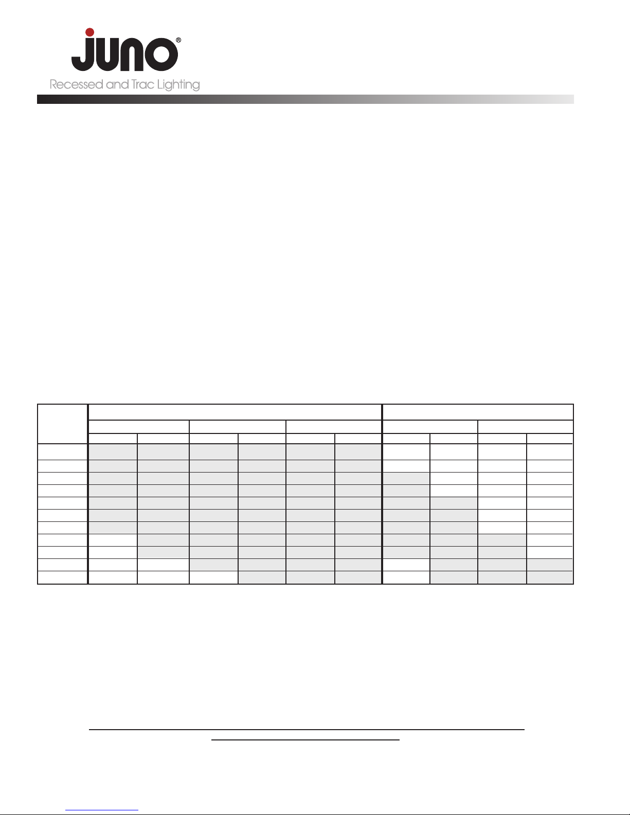
277V INPUT
12V, 6.3A, 75W 12V, 3.3A, 40W 12V, 1.7A, 20W 12V, 6.3A, 75W 12V, 3.3A, 40W
TABLE PREDICTING VOLTAGE AT FIRST LAMP FOR VARIOUS WIRE LENGTHS, GUAGES, INPUT AND LOADS
Distance from
Transformer
to 1st Lamp
BOOST INPUT
#12 #10 #12 #10 #12 #10 #12 #10 #12 #10
FOR MAXIMUM LIGHT OUTPUT, SELECT A WIRE GAUGE AND INPUT TAP (STANDARD OR BOOST) THAT OPERATES THE FIRST LAMP
AS CLOSE TO 12 VOLTS AS POSSIBLE. DO NOT EXCEED 12 VOLTS.
5. A VOLTMETER SHOULD BE USED TO CONFIRM THAT THE PROPER VOLTAGE IS PRESENT.
After the installation is complete, a voltmeter should be used to insure that suggested lamp voltages are not being exceeded. The voltage should
be measured at the first lamp on the trac. Since some of the factors listed above are constantly changing, some allowance should be made for
variations in voltage.
Juno suggests that the voltage measured at the first lamp be between 11.0 and 11.8 volts for 12V incandescent lamps
(between 11.4 and 12.0 volts for 12V LED fixtures).
5 11.53 11.56 11.71 11.73 11.89 11.90 12.18 12.21 12.43 12.46
10 11.46 11.51 11.66 11.70 11.87 11.88 12.09 12.15 12.37 12.43
15 11.39 11.47 11.62 11.67 11.85 11.87 12.00 12.10 12.31 12.39
20 11.31 11.42 11.57 11.64 11.83 11.86 11.91 12.04 12.26 12.35
25 11.24 11.38 11.53 11.61 11.81 11.85 11.82 11.99 12.20 12.32
30 11.17 11.33 11.48 11.58 11.79 11.83 11.73 11.93 12.14 12.28
40 11.03 11.24 11.39 11.52 11.75 11.81 11.56 11.82 12.03 12.21
45 10.95 11.20 11.34 11.49 11.73 11.79 11.47 11.76 11.97 12.17
65 10.67 11.02 11.16 11.38 11.65 11.74 11.11 11.54 11.74 12.03
75 10.52 10.92 11.05 11.31 11.58 11.69 10.93 11.43 11.63 11.95
100 10.17 10.70 10.84 11.18 11.51 11.65 10.49 11.15 11.34 11.77
The shaded areas represent the suggested operating range of 11.0 to 12.0 volts at the first lamp on the trac. Juno suggests that the voltage
measured at the first lamp be between 11.0 and 11.8 volts for 12V incandescent lamps and between 11.4 and 12.0 volts for 12V LED fixtures. Do
not exceed 12 volts. A voltmeter should be used to confirm that the proper voltage is present.
 Loading...