

Page 1
INSTALLATION INSTRUCTIONS
For TUCLF11 and TUCLF21
Trac-Master Two-Circuit Current Limiting End Feed/In-Line Feed Connector
Read and understand these instructions before installing fixture.
This fixture is intended for installation in accordance with the National Electrical Code and local regulations. To
assure full compliance with local codes and regulations, check with your local electrical inspector before installation.
To prevent electrical shock, turn off electricity at main circuit breaker panel before proceeding.
SAVE THESE INSTRUCTIONS
Current Limiting End Feed/In-Line
Feed Connector TUCLF11 and
TUCLF21 for use with Trac-Master
Two-Circuit Trac only. Current
Limiter will limit the wattage on
a circuit and can be used as a
standard ON/OFF switch.
Current limiting feed can be fed using a
4” octagon junction box, fed directly using
flexible or rigid conduit with 3/8” or 1/2”
electrical connector from standard ceilings
or grid ceiling runner systems, or fed using
Trac Pendant Mounting Kits.
NOTE:
1. Turn off power at breaker box before
installing electrical connector and trac.
2. If feeding with electrical connectors do
not use feed connector as a conduit
support. Independent conduit supports
must be used to attach the conduit to the
building structure.
3. Observe polarity; white neutral wire must
be connected to the terminal marked “N” in
the feed connector.
4. Use 12 gauge or 14 gauge solid wire in
feed connector only. Feed connector rating
120V, 20Amp max., 60Hz.
5. Use the proper rated Juno current limiting
circuit breaker (TCL Series) to limit the
load on the circuit (current limiting circuit
breaker sold separately).
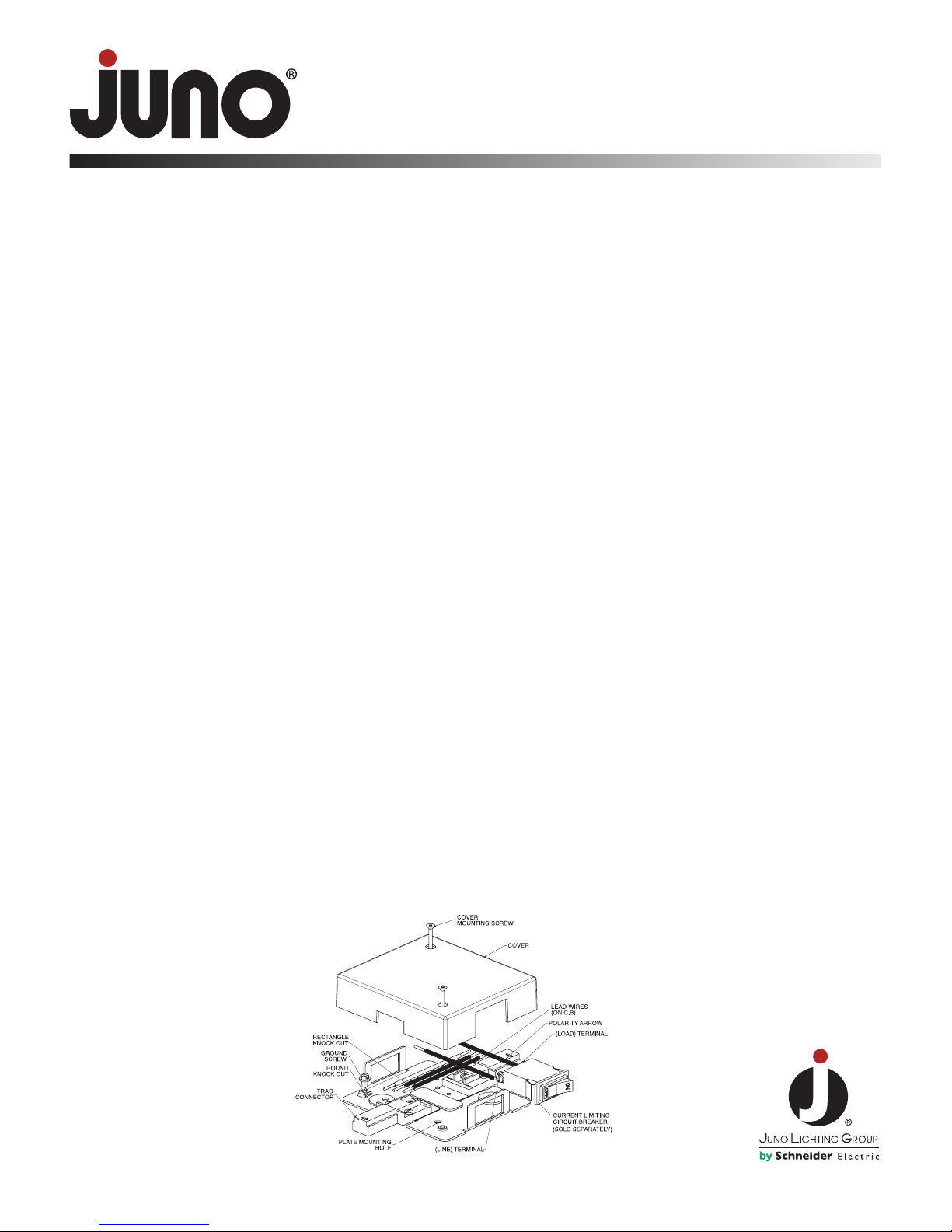
6. Feed connector is polarized and will only
install into one end of the trac. Align
polarity arrow on feed connector toward
trac polarity line for proper installation.
See Figure 1.
7. Do not position luminaire such that it
touches the feed connector.
Note: This Current Limiting Trac Feed
Connector conforms to ASHRAE 90.1
Section 9.1.4(c) and is certified to California
Energy Commission T24-2008, Section
119(L) of the California Energy Code.
INSTALLING CURRENT LIMITING
FEED CONNECTOR ON A J-BOX
The centerline of the trac must be on the
center of the J-Box and the mounting holes
for the J-Box must be at a 45º angle to the
centerline of the trac.
1. Remove the COVER and retain.
2. Remove the RECTANGULAR KNOCK
OUT from the PLATE. Do not remove any
other knock outs.
3. Push CURRENT LIMITING CIRCUIT
BREAKER(S) into PLATE.
4. Fasten PLATE to J-Box passing supply
wires through RECTANGULAR HOLE.
Secure PLATE by passing (2) Mounting
screws (not supplied) through PLATE and
into J-BOX.
5. Attach wires per WIRING INSTRUCTIONS
on page 2.
6. Slide TRAC onto FEED CONNECTOR;
ensure (2) CONTACT BLADES
insert into the gap of the trac BUS BARS.
7. Tighten FEED CONNECTOR ONE-WAY
LOCKING SCREW(S) for permanent
mounting to the trac (in accordance with
CEC-T24-2008.)
8. Apply VA label provided loose with circuit
breaker packaging onto the mounting
plate according to each trac VA rating (in
accordance with CEC-T24-2008.)
9. Fasten COVER taking caution to avoid
pinching any wires.
See OPERATING INSTRUCTIONS on page 2.
INSTALLING CURRENT LIMITING
FEED CONNECTOR USING
FLEXIBLE OR RIGID CONDUIT
1. Remove the COVER and retain.
Figure 1
2. Mark centerline of PLATE on ceiling to
determine the mounting location of the
FEED CONNECTOR.
3. Make a hole in the ceiling for the electrical
connector in the position that coincides
with one of the ROUND KNOCK OUTS.
4. Remove one ROUND KNOCK OUT
where the power is to be passed through.
Do not remove any other knock outs.
5. Push CURRENT LIMITING CIRCUIT
BREAKER(S) into PLATE.
6. Attach electrical connector (by others) to
PLATE in round hole.
7. Pass supply wires through hole in ceiling
and through electrical connector.
8. Mount PLATE to ceiling using (2) of the
PLATE MOUNTING HOLES that are not
located on a knock out. Mounting hardware
not supplied.
9. Attach wires per WIRING INSTRUCTIONS
on page 2.
10. Slide TRAC onto FEED CONNECTOR;
ensure (2) CONTACT BLADES insert
into the gap of the trac BUS BARS.
11. Tighten FEED CONNECTOR LOCKING
SCREW(S).
12. Fasten COVER taking caution to avoid
pinching any wires.
See OPERATING INSTRUCTIONS on page 2.
INSTALLING CURRENT LIMITING
FEED CONNECTOR ON
PENDANT MOUNTED TRAC
1. Follow instructions included with the
pendant mounting kits.
2. Install CURRENT LIMITING CIRCUIT
BREAKER(S) into PLATE.
3. Attach wires per WIRING INSTRUCTIONS
on page 2.
4. Slide TRAC onto FEED CONNECTOR
ensure (2) CONTACT BLADES insert into
the gap of the trac BUS BARS.
5. Tighten FEED CONNECTOR LOCKING
SCREW(S).
6. Fasten COVER taking caution to avoid
pinching any wires.
See OPERATING INSTRUCTIONS on page 2.
1300 South Wolf Road • Des Plaines, IL 60018 • Phone 800-323-5068 • www.junolightinggroup.com
© 2009 Juno Lighting LLC Printed in USA Rev 5/09 P2473 pg 1 of 2
Page 2

INSTALLATION INSTRUCTIONS
For TUCLF11 and TUCLF21
Trac-Master Two-Circuit Current Limiting End Feed/In-Line Feed Connector
END FEED WIRING
INSTRUCTIONS TUCLF11
1. Strip ground wire enough to wrap around
#8 screw. Wrap copper portion of ground
wire around the GREEN GROUND
TERMINAL between the screw and washer.
Clamp wire using screw.
2. Strip White neutral wire 7/16” and connect
to NEUTRAL TERMINAL (N) of FEED
CONNECTOR. Clamp wire using screw.
See schematic Diagram 1.
3. Strip HOT supply wire and connect to
CURRENT LIMITING CIRCUIT BREAKER
LINE Wire (supplied on current limiting
circuit breaker).
4. Connect LOAD wire from CURRENT
LIMITING CIRCUIT BREAKER (supplied
on current limiting circuit breaker) to trac
connector Terminal (P1).
See schematic Diagram 1.
5. Connect jumper wire between (P1) and (P2)
on connector 1.
6. Two current limiting circuit breakers can be
used for end feed applications. See
schematic Diagram 3.
IN-LINE FEED WIRING
INSTRUCTIONS TUCLF21
1. Strip ground wire enough to wrap around
#8 screw. Wrap copper portion of ground
wire around the GREEN GROUND
TERMINAL between the screw and washer.
Clamp wire using screw.
2. Strip White neutral wire 7/16” and connect
to NEUTRAL TERMINAL (N) of FEED
CONNECTOR. Clamp wire using screw.
See schematic Diagram 2.
3. Strip HOT supply wire and connect to
CURRENT LIMITING CIRCUIT BREAKER
LINE Wire (supplied on current limiting
circuit breaker).
4. Connect LOAD wire from CURRENT
LIMITING CIRCUIT BREAKER (supplied
on current limiting circuit breaker) to trac
connector Terminal (P1).
5. Connect (P1) Terminal (connector 1) to (P1)
Terminal (connector 2).
6. Connect (P2) Terminal (connector 1) to (P2)
Terminal (connector 2).
7. Connect (N) Terminal (connector 1) to (N)
Terminal (connector 2).
8. Two current limiting circuit breakers can be
used for in-line applications. See schematic
Diagrams 4, 5 & 6.
OPERATING INSTRUCTIONS
1. Place luminaires on trac. Switch CURRENT
LIMITING CIRCUIT BREAKER(S) to ON
position. Turn main power ON to supply
connector.
• The CURRENT LIMITING CIRCUIT
BREAKER(S) will automatically switch to OFF
if its ratings are exceeded. OFF is designated
by the visibility of a complementary color on the
CURRENT LIMITING CIRCUIT BREAKER(S).
• If CURRENT LIMITING CIRCUIT BREAKER(S)
will not remain on: reduce the wattage on the
trac so the total wattage is less than the wattage
specified on the CURRENT LIMITING CIRCUIT
BREAKER(S). Turn the CURRENT LIMITING
CIRCUIT BREAKER(S) to ON.
Diagram 1 (End Feed)
Diagram 2 (In-Line Feed)
Diagram 3 (End Feed)
Diagram 4 (In-Line Feed)
Diagram 5 (In-Line Feed)
Diagram 6 (In-Line Feed)
WARRANTY
Juno Lighting Group warrants that its products are free from defects in material and workmanship. Juno Lighting Group’s obligation
is expressly limited to repair or replacement, without charge, at Juno Lighting Group’s factory after prior written return authorization has been
granted. This warranty shall not apply to products which have been altered or repaired outside of Juno Lighting Group’s factory. This warranty
is in lieu of all other warranties, expressed or implied, and without limiting the generality of the foregoing phrase, excludes any implied warranty
of merchantability. Also, there are no warranties which extend beyond the description of the product on the company’s literature setting forth
terms of sale.
Product Services Phone (888) 387-2212
1300 South Wolf Road • Des Plaines, IL 60018 • Phone 800-323-5068 • www.junolightinggroup.com
© 2009 Juno Lighting LLC Printed in USA Rev 5/09 P2473 pg 2 of 2
Page 3

INSTRUCCIONES DE INSTALACIÓN
Para TUCLF11 y TUCLF21
Conector de fuente en un extremo/en la línea del limitador de corriente
Trac-Master de dos circuitos
Lea y comprenda estas instrucciones antes de instalar el artefacto.
Este artefacto está diseñado para ser instalado según el Código eléctrico nacional y los reglamentos locales. Para
garantizar el total cumplimiento de los códigos y reglamentos locales, haga las verificaciones correspondientes con
su inspector local de electricidad antes de instalar. Para evitar una descarga eléctrica, corte la electricidad en el
panel del interruptor de circuitos principal antes de comenzar.
GUARDE ESTAS INSTRUCCIONES
Conector de fuente en un extremo/en la
línea del limitador de corriente TUCLF11
y TUCLF21 para utilizar sólo con riel
de dos circuitos Trac. El limitador de
corriente limitará la potencia en vatios
en un circuito y puede utilizarse como
interruptor ON/OFF estándar.
La fuente del limitador de corriente puede
alimentarse utilizando una caja de conexiones
octogonal de 4”, utilizando directamente un
conducto flexible o rígido con un conector
de 3/8” o 1/2” desde cielorrasos estándar o
sistemas de cielorraso suspendido, o utilizando
los conjuntos de montaje colgante con riel.
NOTA:
1. Corte la energía en la caja del interruptor
antes de instalar el conector eléctrico y el
riel.
2. Si está alimentando con conectores
eléctricos, no utilice el conector de la
fuente como soporte del conducto. Debe
utilizar soportes independientes para unir
el conducto a la estructura del edificio.
3. Tenga en cuenta la polaridad; el cable
neutro blanco debe estar conectado al
borne marcado con “N” en el conector de
la fuente.
4. Utilice únicamente cable sólido de 12 o 14
AWG en el conector de la fuente. Potencia
nominal del conector de la fuente 120V,
20Amp máx., 60 HZ.
5. Utilice un interruptor de circuitos para el
limitador de corriente Juno con la potencia
nominal adecuada (Serie TCL) para limitar
la carga en el circuito (el interruptor de
circuitos para el limitador de corriente se
vende por separado).
6. El conector de alimentación está
polarizado y sólo se instalará en un
extremo del riel. Alinee la flecha de
polaridad en el conector de la fuente con
la línea de polaridad del riel para lograr
una correcta instalación. Ver Figura 1.
7. No ubique la luminaria de manera que
toque el conector de la fuente.
Nota: El conector de alimentación del riel
con limitación de corriente cumple la norma
ASHRAE 90.1, Sección 9.1.4(c) y está
certificado conforme a la norma T24-2008
de la Comisión de Energía de California,
Sección 130 (L) del Código de Energía
de California.
INSTALACIÓN DEL CONECTOR
PARA FUENTE CON LIMITADOR
DE CORRIENTE EN UNA CAJA
DE CONEXIÓN
La línea central del riel debe estar en el centro
de la caja de conexiones y los orificios de
montaje de la caja deben formar un ángulo de
45° con la línea central del riel.
1. Retire la TAPA y sujete.
2. Retire la TAPA CIEGA RECTANGULAR de
la PLACA. No retire las otras tapas ciegas.
3. Empuje el/los INTERRUPTORES DE
CIRCUITOS DEL LIMITADOR DE
CORRIENTE hacia dentro de la PLACA.
4. Sujetar PLACA a cables de alimentación
de la caja de conexiones a través del
ORIFICIO RECTANGULAR. Asegurar la
PLACA pasando los (2) tornillos de
montaje (no provistos) a través de la
PLACA y en la CAJA DE CONEXIONES.
5. Conecte los cables según se indica en las
INSTRUCCIONES DE CABLEADO de la
página 2.
6. Deslice el RIEL sobre el CONECTOR DE
LA FUENTE; verifique que las (2)
CUCHILLAS DE CONTACTO se inserten
en la ranura de las BARRAS BUS del riel.
7. Apriete el o los TORNILLOS DE
BLOQUEO UNIDIRECCIONALES DEL
CONECTOR DE ALIMENTACIÓN para
montaje permanente al riel (según la norma
CEC-T24-2008.)
8. Aplique la etiqueta de VA provista en el
envase del disyuntor (suelta) en la placa de
montaje, de acuerdo a los VA nominales de
cada riel (según la norma CEC-T24-2008.)
9. Apriete la CUBIERTA con precaución para
evitar estrangular los cables.
Vea las INSTRUCCIONES OPERATIVAS en
la página 2.
Figura 1
INSTALACIÓN DE CONECTOR
PARA FUENTE CON LIMITADOR
DE CORRIENTE UTILIZANDO
CONDUCTO FLEXIBLE O RÍGIDO
1. Retire la TAPA y sujete.
2. Marque la línea central de la PLACA en el
cielorraso para determinar el lugar de
montaje del CONECTOR DE LA FUENTE.
3. Haga un orificio en el cielorraso para el
conector eléctrico en la posición que
coincida con una de las TAPAS CIEGAS
CIRCULARES.
4. Retire una TAPA CIEGA CIRCULAR en el
lugar por el que deba pasar la energía. No
retire las otras tapas ciegas.
5. Empuje el/los INTERRUPTORES DE
CIRCUITOS DEL LIMITADOR DE
CORRIENTE hacia dentro de la PLACA.
6. Conecte el conector eléctrico (por otros) a
la PLACA en el orificio redondo.
7. Pase los cables de alimentación a través
del orificio en el cielorraso y a través del
conector eléctrico.
8. Monte la PLACA en el cielorraso utilizando
(2) de los ORIFICIOS DE MONTAJE DE
LA PLACA que no estén ubicados en una
tapa ciega. Los elementos para el montaje
no están incluidos.
9. Conecte los cables según se indica en las
INSTRUCCIONES DE CABLEADO de la
página 2.
10. Deslice el RIEL sobre el CONECTOR DE
LA FUENTE; verifique que las (2)
CUCHILLAS DE CONTACTO se inserten
en la ranura de las BARRAS BUS del riel.
11. Ajuste el/losTORNILLO(S) DE FIJACIÓN
DEL CONECTOR DE LA FUENTE.
12. Ajuste la TAPA con la precaución de evitar
pellizcar los cables.
Vea las INSTRUCCIONES OPERATIVAS en
la página 2.
INSTALACIÓN DE CONECTOR
PARA FUENTE CON LIMITADOR
DE CORRIENTE EN RIEL
COLGANTE
1. Siga las instrucciones incluidas en los
conjuntos de montaje colgante.
2. Instale el/los INTERRUPTOR/ES DE
CIRCUITOS LIMITADORES DE
CORRIENTE en la PLACA.
3. Conecte los cables según las
INSTRUCCIONES DE CABLEADO que
aparecen a continuación.
4. Deslice el RIEL sobre el CONECTOR
PARA FUENTE y verifique que las (2)
CUCHILLAS DE CONTACTO se inserten
en la ranura de las BARRAS BUS del riel.
5. Ajuste el/losTORNILLO(S) DE FIJACIÓN
DEL CONECTOR DE LA FUENTE.
6. Ajuste la TAPA con la precaución de evitar
pellizcar los cables.
Vea las INSTRUCCIONES OPERATIVAS en
la página 2.
© 2009 Juno Lighting LLC Impreso en EE.UU. Rev 05/09 P2473 pág. 1 de 2
Page 4

INSTRUCCIONES DE INSTALACIÓN
Para TUCLF11 y TUCLF21
Conector de fuente en un extremo/en la línea del limitador de corriente
Trac-Master de dos circuitos
INSTRUCCIONES DE CABLEADO
DE ALIMENTACIÓN EN EXTREMO
TUCLF11
1. Pele suficiente cable de descarga a tierra
para enrollar alrededor del tornillo #8.
Envuelva la parte de cobre del cable a tierra
alrededor del BORNE VERDE A TIERRA
entre el tornillo y la arandela. Sujete el
cable utilizando el tornillo.
2. Pele el cable neutro blanco de 7/16” y
conéctelo al BORNE NEUTRO (N) del
CONECTOR DE LA FUENTE. Sujete el
cable utilizando el tornillo. Ver Diagrama 1.
3. Pele el conductor de alimentación HOT
(Vivo) y conéctelo al conductor LINE
del DISYUNTOR LIMITADOR DE
CORRIENTE (suministrado en dicho
disyuntor).
4. Conecte el conductor LOAD (Carga) del
DISYUNTOR LIMITADOR DE CORRIENTE
(suministrado en dicho disyuntor) al terminal
(P1) del conector del Trac.
Ver Diagrama 1.
5. Connect jumper wire between (P1) and (P2)
on connector 1.
6. Pueden utilizarse dos interruptores de
limitadores de corriente para las
aplicaciones de fuente en un extremo.
Ver Diagrama 3.
INSTRUCCIONES DE CABLEADO
DE ALIMENTACIÓN EN LÍNEA
TUCLF21
1. Pele suficiente cable de descarga a tierra
para enrollar alrededor del tornillo #8.
Envuelva la parte de cobre del cable a tierra
alrededor del BORNE VERDE A TIERRA
entre el tornillo y la arandela. Sujete el cable
utilizando el tornillo.
2. Pele el cable neutro blanco de 7/16” y
conéctelo al BORNE NEUTRO (N) del
CONECTOR DE LA FUENTE. Sujete el
cable utilizando el tornillo. Ver Diagrama 2.
3. Pele el conductor de alimentación HOT
(Vivo) y conéctelo al conductor LINE del
DISYUNTOR LIMITADOR DE CORRIENTE
(suministrado en dicho disyuntor).
4. Conecte el conductor LOAD (Carga) del
DISYUNTOR LIMITADOR DE CORRIENTE
(suministrado en dicho disyuntor) al terminal
(P1) del conector del Trac.
5. Conecte el Borne (P1) (conector 1) al Borne
(P1) (conector 2).
6. Conecte el Borne (P2) (conector 1) al
Borne (P2) (conector 2).
7. Conecte el Borne (N) (conector 1) al Borne
(N) (conector 2).
8. Pueden utilizarse dos interruptores de
limitadores de corriente para las
aplicaciones en línea. Ver Diagramas 4,
5 y 6.
INSTRUCCIONES OPERATIVAS
1. Coloque las luminarias sobre el riel. Coloque
el /los INTERRUPTOR(ES) DE CIRCUITO
DEL LIMITADOR DE CORRIENTE en
posición ON. Encienda el suministro
principal (ON) para alimentar el conector.
• El /los INTERRUPTOR(ES) DE CIRCUITO
DEL LIMITADOR DE CORRIENTE pasarán
automáticamnete a OFF si se exceden sus
potencias nominales. OFF está indicado por la
visualización de un color suplementario en el /
los INTERRUPTOR(ES) DE CIRCUITOS DEL
LIMITADOR DE CORRIENTE.
• Si el /los INTERRUPTOR(ES) DE CIRCUITO
DEL LIMITADOR DE CORRIENTE no
permanence encendidos: Reduzca la potencia
en vatios en el riel de modo que la potencia
total sea inferior a la especificada en el /los
INTERRUPTOR(ES) DE CIRCUITO DEL
LIMITADOR DE CORRIENTE. Coloque el /
los INTERRUPTOR(ES) DE CIRCUITO DEL
LIMITADOR DE CORRIENTE en posición ON.
Diagrama 1 (Alimentación en extremo)
Diagrama 2 (Alimentación en línea)
Diagrama 3 (Alimentación en extremo)
Diagrama 4 (Alimentación en línea)
Diagrama 5 (Alimentación en línea)
Diagrama 6 (Alimentación en línea)
GARANTÍA
Juno Lighting Group garantiza que sus productos están libres de defectos de material o mano de obra. La obligación de Juno Lighting
Group se limita expresamente a la reparación o el reemplazo sin cargo, en la fábrica de Juno Lighting Group, previo otorgamiento de una
autorización de devolución por escrito. Esta garantía no cubre los productos que han sido alterados o reparados fuera de la fábrica de
Juno Lighting Group. Esta garantía reemplaza a todas las demás garantías, expresas o implícitas y, sin limitar la generalidad de la frase
precedente, excluye toda garantía implícita de comerciabilidad. Además, no existen garantías que se extiendan más allá de la descripción del
producto en la literatura de la compañía que establece los términos de venta.
Teléfono de servicio de productos (888) 387-2212
1300 South Wolf Road • Des Plaines, IL 60018 • Teléfono 800-323-5068 • www.junolightinggroup.com
© 2009 Juno Lighting LLC Impreso en EE.UU. Rev 05/09 P2473 pág. 2 de 2
Page 5

Le connecteur d’alimentation en ligne/en bout limiteur de courant à Circuit
double Trac-Master
Lisez et assurez-vous d’avoir compris ces instructions avant de monter le luminaire.
Ce luminaire est conçu pour un montage conforme aux règlements du National Electrical Code et des règlements
locaux. Pour vous assurer de la conformité absolue avec les codes et règlements locaux, vérifiez auprès de votre
inspecteur électricien local avant le montage Pour éviter toute électrocution, coupez l’alimentation au disjoncteur
central avant de commencer.
CONSERVEZ LES PRÉSENTES INSTRUCTIONS
Connecteur d’alimentation en ligne/en
bout limiteur de courant TUCLF11 et
TUCLF21 pour le rail à circuit double
Trac-Master uniquement. Le limiteur de
courrant limitera la puissance sur un
circuit et peut servir de commutateur de
MARCHE/ARRÊT normal.
L’alimentation à limitation de courant peut
être acheminé à l’aide d’un boîtier de jonction
octogonale de 10 cm (4 po), directement moyen
d’une canalisation souple ou rigide de 0,9 cm
(3/8 po) ou 1,3 cm (_ po) des plafonds normaux
ou des plafonds à grille, ou acheminé à l’aide
d’une fixation suspendu de rail.
Remarque :
1. Coupez l’alimentation au disjoncteur avant
de monter le connecteur électrique et le rail.
2. Si vous alimentez avec des connecteurs
électriques, n’utilisez pas le connecteur
d’alimentation en guise de support de
canalisation. Des supports de canalizations
indépendants doivent fixer la canalisation à
la structure de l’édifice.
3. Conformez-vous à la polarité ; le fil neutre
blanc doit être connectée à la borne
portant un « N » du connecteur
d’alimentation.
4. Utilisez du fil massif de calibre 12 ou 14
dans le connecteur d’alimentation
uniquement. Puissance du connecteur
d’alimentation 120 V, 20 A maxi, 60 Hz.
5. Utilisez un disjoncteur limiteur de courant
Juno de la bonne puissance (Série TCL)
pour limiter la charge du circuit (disjoncteur
limiteur de courant vendu séparément).
6. Le connecteur d’alimentation est polarisé et
ne peut se monter qu’à un bout du rail.
Alignez la polarité du connectuer
d’alimentation vers la ligne de polarité du
rail pour un bon montage. Voir Figure 1.
7. Ne positionnez pas le luminaire de sorte
qu’il entre en contact avec le connecteur
d’alimentation.
Remarque : Le connecteur d’alimentation
de rail à limitation de courant est conforme
à la norme ASHRAE 90.1 Section 9.1.4(c )
et est certifié conforme à la norme T24-2008
de la California Energy Commission,
Section 119 (L) du California Energy Code.
MODE DE MONTAGE
Pour TUCLF11 et TUCLF21
MONTAGE DU CONNECTEUR
D’ALIMENTATION À LIMITATION
DE COURANT À L’AIDE D’UNE
MONTAGE D’UN CONNECTEUR
D’ALIMENTATION LIMITEUR DE
COURANT SUR UNE BOÎTE DE
CONNEXION
La ligne médiane du rail doit être au centre de
la boîte de connexion et les trous de fixation
doivent être à un angle de 45° par rapport à la
ligne médiane du rail.
1. Retirez le couvercle et mettez-le de côté.
2. Retirez l’ALVÉOLE DÉFONÇABLE
RECTANGULAIRE de la PLAQUE.
N’enlevez aucune autre alvéoles
défonçacles.
3. Poussez le(s) DISJONCTEUR(S) À
LIMITATION DE COURANT dans la
PLAQUE.
4. Assujettissez la PLAQUE à la boîte de
connexion en passant le fils à travers le
TROU RECTANGULAIRE. Assujettissez la
PLAQUE en passant (2) vis de fixation
(non comprises) à travers la PLAQUE et
dans la BOÎTE DE CONNEXION.
5. Fixez les fils conformément aux
INSTRUCTION DE CÂBLAGE de la page 2.
6. Glissez le RAIL sur le CONNECTEUR
D’ALIMENTATION ; assurez-vous que les
(2) LAMES DE CONTACT s’introduisent
dans l’espacement des BARRES OMNIBUS
du rail.
7. Serrer la/les VIS DE BLOCAGE À
SENS UNIQUE DU CONNECTEUR
D’ALIMENTATION pour une fixation
permanente sur le rail (selon la norme
CEC-T24-2008).
8. Appliquer l’autocollant VA avec l’emballage
du disjoncteur (en vrac) sur la plaque de
fixation selon la classification VA de chaque
RAIL (selon la norme CEC-T24-2008).
9. Assujettir le couvercle en veillant à ne pas
pincer les fils.
Voir les INSTRUCTIONS DE
FONCTIONNEMENT de la page 2.
Figure 1
© 2009 Juno Lighting LLC Imprimé aux Etats-Unis Rev 05/09 P2473 pg 1 de 2
CANALISATION SOUPLE OU
RIGIDE
1. Retirez le couvercle et mettez-le de côté.
2. Repérez la ligne médiane de la PLAQUE
sur le plafond afin de déterminer le lieu de
fixation du CONNECTEUR
D’ALIMENTATION.
3. Pratiquez un trou dans le plafond pour le
connecteur électrique dans une position
qui coïncide avec l’une des ALVÉOLES
DÉFONÇABLES RONDES.
4. Retirez une ALVÉOLE DÉFONÇABLE
RONDE à l’endroit où l’alimentation doit
passer. N’enlevez aucune autre alvéoles
défonçacles.
5. Poussez le(s) DISJONCTEUR(S) À
LIMITATION DE COURANT dans la
PLAQUE.
6. Fixez le connecteur électrique (d’une autre
marque) à la PLAQUE dans le trou rond.
7. Passez les fils d’alimentation dans le trou
du plafond et à travers le connecteur
électrique.
8. Montez la PLAQUE sur le plafond à l’aide
de (2) TROUS DE FIXATION DE LA
PLAQUE qui ne soient pas situés sur une
alvéole défonçable. Les pièces de fixation
ne sont pas fournies.
9. Fixez les fils conformément aux
INSTRUCTIONS DE CÂBLAGE de la
page 2.
10. Glissez le RAIL sur le CONNECTEUR
D’ALIMENTATION ; assurez-vous que les
(2) LAMES DE CONTACT s’introduisent
dans l’espacement des BARRES
OMNIBUS du rail.
11. Serrez la/les VIS DE BLOCAGE DU
CONNECTEUR D’ALIMENTATION.
12. Assujettissez le COUVERCLE en veillant à
ne pas pincer les fils.
Voir les INSTRUCTIONS DE
FONCTIONNEMENT de la page 2.
MONTAGE DU CONNECTEUR
D’ALIMENTATION SUR UN RAIL
SUSPENDU
1. Conformez-vous aux instructions figurant
dans les trousses de fixation de la
suspension.
2. Montez le(s) DISJONCTEUR(S) À
LIMITATION DE COURANT dans la
PLAQUE.
3. Fixez les fils conformément aux
INSTRUCTIONS DE CÂBLAGE ci-dessous.
4. Glissez le RAIL sur le CONNECTEUR
D’ALIMENTATION ; assurez-vous que les
(2) LAMES DE CONTACT s’introduisent
dans l’espacement des BARRES OMNIBUS
du rail.
5. Serrez la/les VIS DE BLOCAGE DU
CONNECTEUR D’ALIMENTATION.
6. Assujettissez le COUVERCLE en veillant à
ne pas pincer les fils.
Voir les INSTRUCTIONS DE
FONCTIONNEMENT de la page 2.
Page 6

MODE DE MONTAGE
Pour TUCLF11 et TUCLF21
Le connecteur d’alimentation en ligne/en bout limiteur de courant à Circuit
double Trac-Master
INSTRUCTIONS DE CÂBLAGE
D’ALIMENTATION PAR LE BOUT
TUCLF11
1. Dénudez une longueur suffisante du fil de
terre pour l’enrouler autour de la vis N°8.
Enroulez la partie en cuivre du fil de terre
autour de LA BORNE DE TERRE VERTE
entre la vis et la rondelle. Serrez le fil à
l’aide de la vis.
2. Dénudez le fil neutre blanc sur 11 mm (7/16
po) et connectez-le À LA BORNE NEUTRE
(N) du CONNECTEUR D’ALIMENTATION.
Serrez le fil à l’aide de la vis. Voir le
Schéma 1.
3. Dénuder le fil d’alimentation ACTIF et le
connecter au fil de la LIGNE DE
DISJONCTEUR LIMITEUR DE COURANT
(fourni sur le disjoncteur limiteur de
courant).
4. Connecter le fil de CHARGE du
DISJONCTEUR LIMITEUR DE COURANT
(fourni sur le disjoncteur limiteur de courant)
à la borne (P1) du connecteur de rail.
Voir le Schéma 1.
5. Connectez un cavalier entre (P1) et (P2) sur
le connecteur 1.
6. Deux disjoncteurs à limiteur de courant
peuvent être utilisés pour les applications à
alimentation par le bout. Voir le Schéma 3.
INSTRUCTIONS DE CÂBLAGE
DE L’ALIMENTATION EN LIGNE
TUCLF21
1. Dénudez une longueur suffisante du fil de
terre pour l’enrouler autour de la vis N°8.
Enroulez la partie en cuivre du fil de terre
autour de LA BORNE DE TERRE VERTE
entre la vis et la rondelle. Serrez le fil à l’aide
de la vis.
2. Dénudez le fil neutre blanc sur 11 mm (7/16
po) et connectez-le À LA BORNE NEUTRE
(N) du CONNECTEUR D’ALIMENTATION.
Serrez le fil à l’aide de la vis. Voir le
Schéma 2.
3. Dénuder le fil d’alimentation ACTIF et le
connecter au fil de la LIGNE DE
DISJONCTEUR LIMITEUR DE COURANT
(fourni sur le disjoncteur limiteur de courant).
4. Connecter le fil de CHARGE du
DISJONCTEUR LIMITEUR DE COURANT
(fourni sur le disjoncteur limiteur de courant)
à la borne (P1) du connecteur de rail.
5. Connectez la Borne (P1) (connecteur 1) à la
Borne P2 (connecteur 2).
6. Connectez la Borne (P2) (connecteur 1) à la
Borne (P2) (connecteur 2).
7. Connectez la Borne (N) (connecteur 1) à la
Borne N (connecteur 2).
8. Deux disjoncteurs à limiteur de courant
peuvent être utilisés pour les applications en
ligne. Voir les Schémas 4, 5 et 6.
INSTRUCTIONS DE
FONCTIONNEMENT
1. 1. Placez les luminaires sur le rail. Mettez
le(s) DISJONCTEUR(S) À LIMITATION DE
COURANT sur la position de MARCHE.
Mettez le connecteur d’alimentation sur le
secteur et sur MARCHE.
• Le(s) DISJONCTEUR(S) À LIMITATION DE
COURANT se mettront automatiquement sur
ARRÊT dès lors que sa/leur puissance nominale
sera dépassée. ARRÊT est désigné par la
visibilité d’une couleur complémentaire sur le(s)
DISJONCTEUR À LIMITATION DE COURANT.
• SI le(s) DISJONCTEUR(S) À LIMITATION
DE COURANT ne demeurent pas en position
de marche : Réduire la puissance sur le rail de
façon à ce que cette dernière soit inférieure à la
puissance spécifiée sur le9s) DISJONCTEUR(S)
À LIMITATION DE COURANT. Mettez
le(s) DISJONCTEUR(S) À LIMITATION DE
COURANT sur la position de MARCHE.
Schéma 1 (Alimentation en bout)
Schéma 2 (Alimentation en ligne)
Schéma 3 (Alimentation en bout)
Schéma 4 (Alimentation en ligne)
Schéma 5 (Alimentation en ligne)
Schéma 6 (Alimentation en ligne)
GARANTIE
Juno Lighting Group garantit que ses produits sont exempts de défauts de matière et de façon. L’obligation de Juno Lighting Group se limite
expressément à la réparation ou au remplacement, à titre gratuit, à l’usine de Juno Lighting Group après qu’une autorisation écrite de retour
ait été préalablement accordée. Ladire garantie ne s’appliquera pas aux produits modifiés ou réparés hors d’une usine de Juno lIghting Group.
La présente garantie remplace toute autre garantie, expresse ou implicite, et sans limiter le caractère général de la locution précédente,
exclut toute garantie implicite de qualité marchande. De même, il n’est offert aucune garantie qui s’étende au-delà de la description de produit
figurant sur la documentation de la société énonçant les conditions de vente.
Téléphone Services de produits (888) 387-2212
1300 South Wolf Road • Des Plaines, IL 60018 • Téléphone 800-323-5068 • www.junolightinggroup.com
© 2009 Juno Lighting LLC Imprimé aux Etats-Unis Rev 05/09 P2473 pg 2 de 2
 Loading...