

JUNO Optim FreedomView FVSD320, Optim FreedomView FVSD440, Optim FreedomView FVSD312, Optim FreedomView FVSD340, Optim FreedomView FVSD420 User Manual
Page 1
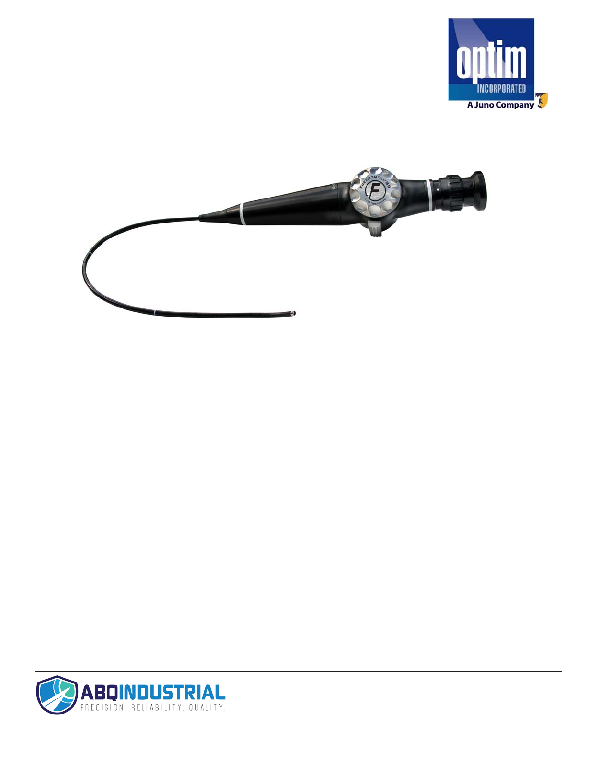
FreedomView
Inspection Kits
®
SD LED Fiberscope
Part No. 00
Part No. 0063252 FVSD340
Part No. 006307 FVSD312
Part No. 0062971 FVSD420
Part No. 0062972 FVSD440
63251 FVSD320
Tel: +1 (281) 516-9292 / (888) 275-5772 eFax:
Web: http
s://www.abqindustrial.net E-mail: info@abqindustrial.net
Distributed by: ABQ Industrial LP USA
+1 (866) 234-0451
1
Page 2

Table of Contents
TOPIC PAGE #
1. Introduction
2. Fiberscope Description
3
4
3. Operating the FreedomView® SD LED Fiberscope Inspection Kit 5
Fiberscope 5
A. Focusing the FreedomView® SD LED Fiberscope
B. Articulating the FreedomView® SD LED Fiberscope
C. Internal LED Light Source
D. Adjusting the Light Intensity Control
E. Operating Temperature
F. Immersion of Components
G. Cleaning
Lithium-Ion Battery and Battery Charger 7
A. To Charge a Battery
B. To Change a Battery
4. Storage 9
5. Photography 9
6. Troubleshooting 10
7. Technical Specifications 11
8. Parts & Accessories 12
9. Service
13
10. Warranty 14
11. Symbol Descriptions 15
12. Vendor Information 15
5
6
6
6
6
6
7
7
8
2
Page 3

1. Introduction
The OPTIM Incorporated FreedomView® SD LED Fiberscope Inspection Kit is a simple, nondestructive visual
inspection system. It enables the user to observe inaccessible, interior portions of structures in a wide variety of
applications.
This fiber optic viewing instrument is constructed of high quality, durable materials and is desig ned for simplified
integrations with complimentary components.
Read this manual thoroughly to familiarize yourself with all components prior to the first use. The manual contains
care and handling information which will help extend the life of the instrument.
NOTE: Read this manual completely.
All WARNINGS and CAUTIONS are printed in BOLD LETTERS.
3
Page 4
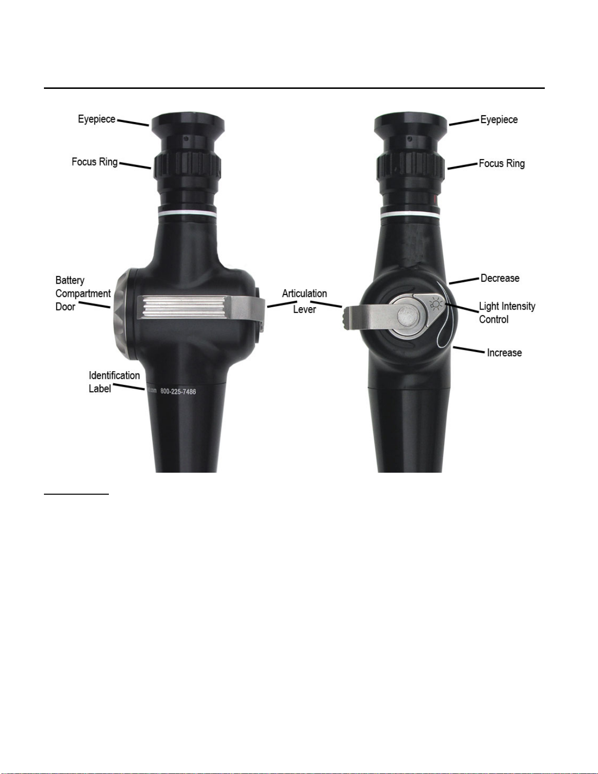
2. Fiberscope Description
Control Body:
Eyepiece: The eyepiece allows the user to visualize the image directly or to connect a standard video camera, still
photography system, or teaching attachment to the endoscope. The eyepiece is compatible with most C-mount
adapters and video camera systems. Call OPTIM Incorporated at +1.508.347.5100 or 800.225.7486 for information
on video adapters, cameras, processors and monitors.
Focus Ring: The focus ring adjusts the image to the user’s eyesight. Adjust the focus by rotating the Focus Ring
(also known as the Diopter Adjustment Ring) clockwise or counterclockwise until the fiber pattern is in clear focus.
Diopter Markings: If using a video camera, still photography system, or teaching attachment, the white dot on the
Control Body must be aligned with the white dot on the Focus Ring (Diopter Adjustment Ring). The colored lines
provide reference markers for various users of the same endoscope.
Articulation Lever: The articulation lever controls the angular deflection of the Distal Tip.
Light Switch Lever: The light switch lever controls the on / off and intensity of light output. Moving the lever
towards the wider end of the intensity indicator increases the light intensity; moving the lever towards the narrower
end of the intensity indicator decreases the light intensity.
Battery Door: The battery door seals the battery and electronics wi thin the control body.
4
Page 5

3. Operating the FreedomView® SD LED Fiberscope Inspection Kit
• Hold the fiberscope so that the control body fits comfortably in one hand, allowing easy manipulation of the
articulation lever with the thumb. Use the other hand to manipulate the Insertion Tube of the fiberscope.
CAUTION: Avoid excessive bending or twisting of the fiberscope insertion shaft. While designed to
bend, excessive pressure can damage the fibers and internal components. Do not manually bend the
distal tip; always use the articulation lever to articulate the tip up or down.
• When using a video camera or still photography system, be sure the white dot on the Control Body is
aligned with the white dot on the Focus Ring.
• Turn on the light by rotating the lever on the side of the Control Body near the Articulation Lever. Adjust the
brightness to the desired level by the rotating lever.
• At the completion of the inspection, remove the fiberscope under direct visualization and with the
Articulation Lever in the neutral position.
SAFETY RULES
1. Do not attempt to use this device for any application in which the operator is untrained or unfamiliar.
2. Do not tamper with the power supply.
3. Provide adequate ventilation for the battery charger to prevent overheating.
4. Avoid damage to the power cords. Never carry the scope or charger by the cord. Keep the power cords
away from heat, extreme cold, oil, solvents and sharp edges.
5. The handle assembly contains electrical components. DO NOT use in an explosive environm ent. DO
NOT immerse or expose the handle assembly to liquids of any type.
6. The high intensity light at the tip of the scope is extremely bright. To minimize the risk of injury, avoid
direct viewing of the light.
When illumination is not required, even for short intervals, turn the light source power off. This will extend battery life
and reduce heat build up.
FIBERSCOPE
Before proceeding with your internal inspection, obtain a sample or cut-away section of the item to be
inspected. Practice the inspection several times outside the object. Familiarize yourself with the operating
characteristics of the FreedomView
observations. It is not uncommon to experience difficulty in positioning the objective end of the LED
Fiberscope during initial inspections.
A. Focusing the FreedomView
FreedomView
®
LED Fiberscope has two distinct features involved in focus.
1. Diopter Adjustment within the Eyepiece:
The diopter adjustment allows an operator to focus the eyepiece. Rotate the diopter ring, in
either direction, for desired focus.
2. Objective or Target End of the LED Fiberscope:
The objective end of the FreedomView
with a fixed range (Please refer to Specifications Section 7).
The optimal image focal distance (Please refer to Specifications Section 7). The lens system is capable of
imaging targets as far away as fifteen (15) feet. Target magnification is determined by the objective lenses
field of view and distance from the target. The FreedomView
(1:1) magnification ratio at 25mm (1 inch) from the target. Moving the Fiberscope’s objective end closer to
the target increases target image size. Moving it away from the target decreases target image size.
®
SD LED Fiberscope. Practice your access path and diagnostic
®
SD LED Fiberscope
®
SD LED Fiberscope has a fixed focus lens at the tip
®
SD LED Fiberscope provides a one-to-one
5
Page 6

B. Articulating the FreedomView
The FreedomView
®
SD LED Fiberscope has two-way end tip articulation. The articulating tip is connected
®
SD LED Fiberscope
to the articulation control lever located on the handle.
NEVER FORCE THE ARTICULATION LEVER. FORCING THE ARTICULATION CONTROL WILL
SEVERELY DAMAGE THE INSTRUMENT.
If the articulation control becomes frozen or sluggish, discontinue use and conta ct OPTIM Incorporated.
IT MAY BE POSSIBLE TO PREVENT EXTENSIVE DAMAGE IF THE PROPER PRECAUTIONS ARE
TAKEN IMMEDIATELY WHEN ANY ABNORMALITIES ARE DISCOVERED.
C. Internal LED Light Source
The FreedomView
The FreedomView
ion battery, which is inserted into the handle of the LED Fiberscope. The battery pack makes the
entire LED Fiberscope completely portable. A charger is included in the FreedomView
®
SD LED Fiberscope source of power:
®
SD LED Fiberscope’s internal LED light source operates on a singl e, Lithium
®
SD LED
Fiberscope kit. Two hours of charge to the lithium-ion battery produces and provides approximately
30-40 minutes of continuous operation when a new battery is fully charged. When the battery is
drained, the light will flicker on and off indicating it is time to recharge the battery. Two batteries are
included in the FreedomView
®
SD LED Fiberscope Kit. Additional batteries are available.
D. Adjusting the Light Intensity
Turn on the light by rotating the lever on the side of the Control Body near the Articulation Lever. Adjust the
brightness to the desired level by the rotating lever.
WARNING – DO NOT LOOK DIRECTLY AT THE BRIGHT LIGHT FROM THE FIBERSCOPE
E. Operating Temperature
The Fiberscope Inspection Kit has an operating temperature range from 0° to 122° F. Avoid Articulation
Below 0° F. Under low temperature conditions, articulation becomes restricted and, if forced, can cause
the articulation wires to stretch or break.
F. Immersion of Components
The insertion shaft of the FreedomView
®
SD LED Fiberscope has been tested for immersion in water,
gasoline and diesel fuel. For immersion in other liquids, consult the manufacturer prior to use. Some caustic
liquids may cause severe damage to the insertion shaft. In the event the FreedomView fiberscope shaft
becomes contaminated with any material or organic liquids, the shaft should be washed with a mild
detergent and water. The shaft should be air dried completely after cleaning. Always clean any organic
material from the shaft prior to storing the fiberscope.
DO NOT IMMERSE THE LED FIBERSCOPE HANDLE IN ANY LIQUID.
6
Page 7

G. Cleaning
Wipe the shaft periodically with a clean dry rag. Use a cotton swab saturated with 70% isopropyl alcohol to
clean the lenses. Dry with a lint-free cloth.
DO NOT put unnecessary pressure on the articulation section when cleaning the objective lens. Hold the
stainless steel end tip while the instrument is positioned on a clean, dry surface.
DO NOT CLEAN THE INSTRUMENT WITH ORGANIC SOLVENTS OF ANY TYPE. SOME SOLVENTS
MAY CAUSE DETERIORATION OF THE SHAFT.
THE FREEDOM VIEW
®
SD LED FIBERSCOPE EYEPIECE IS NOT WATERTIGHT. CLEAN THE
OCCULAR LENS IN THE EYEPIECE WITH ALCOHOL ONLY.
LITHIUM ION BATTERY & BATTERY CHARGER& AC POWER SUPPLY
The FreedomView
®
SD LED Fiberscope’s internal LED light source operates on a single, Lithium ion battery and
provides approximately 40 minutes of continuous operation when a new battery is fully charged. When the battery is
drained, the light will flicker on and off indicating it is time to recharge the battery.
CAUTION:
• Do not incinerate the battery
• Do not expose the battery to high temperatures above 122ºF/50ºC
• Do not disassemble the battery
• Do not short circuit the battery
A. To Charge a Battery:
• First plug the AC adapter into a wall outlet.
• Connect the AC power adapter to the DC IN jack located at the back of the charger. The “STATUS”
indicator will be solid RED when the charger is ready and the “CHARGE” indicator will be flas hing GREEN
when the charger is waiting for a battery to charge.
• Slide the battery into the charger, making sure the end of the battery with the two gold electrical contacts is
inserted into the charger first. The “CHARGE” indicator will turn RED when the battery is charging.
7
Page 8

• The “CHARGE” indicator will alternately flash RED and GREEN when the battery has been charged to over
90%.
• When the battery is fully charged, the “CHARGE” indicator will turn solid green.
• After the battery has been fully charged, slide the battery out of the charger and unplug the AC adapter for
the charger.
B. To Change a Battery:
• To remove the battery, simply unscrew the stainless steel battery cap and turn the scope handle over so the
battery drops out into your other hand. Please take care not to let the battery fall to the floor or onto a hard
object, which could damage the battery.
• To insert a new battery, align the battery with the cutout in the battery compartment, making sure the end of
the battery with the two gold electrical contacts is inserted into the battery compartment first.
• Once a charged battery is inserted into the scope handle, replace the battery compartment cap by screwing
the cap clockwise until a tight seal is made.
CAUTION: This equipment is not suitable for use in the presence of flammable mixtures.
8
Page 9

4. Storage
CLOSING THE CARRYING CASE LID ON AN IMPROPERLY STORED INSTRUMENT IS ONE OF THE MOST
COMMON CAUSES OF DAMAGE.
The FreedomView® SD LED Fiberscope Inspection Kit may be stored and transported at temperatures ranging from
-60° F to + 122° F.
ALLOW THE INSTRUMENT TO WARM UP OR COOL DOWN TO OPERATING TEMPERATURE PRIOR TO
USE.
The FreedomView® SD LED Fiberscope’s case and insert are designed to provide optimum protection during
storage and transport. When the Fiberscope is not in use, put it into the foam insert with the shaft below the top of
the insert. Always store and transport Fiberscope components in the carrying case.
If the FreedomView® SD LED Fiberscope Inspection Kit has been stored for an extended period of time, check the
battery pack prior to use.
Lithium-Ion batteries can be stored in charged or uncharged condition for extended periods wi thout significant loss
of performance. Partial self-discharge during storage is a normal.
5. Photography
Contact OPTIM’s customer service department at (800) 225-7486 for information concerning di gital still and video
photography.
9
Page 10

6. Troubleshooting
If abnormalities occur during FreedomView
consult Optim, Incorporated.
DO NOT ATTEMPT SELF-REPAIR!
IMAGE IS NOT CLEAR
POSSIBLE CAUSE SOLUTION
Eyepiece diopter not adjusted Adjust diopter ring until fiber pattern
to user’s vision: is in clear, sharp focus.
Target is out of focus: Reposition objective end to focal
distance of 6mm-100mm.
Contaminant on lens: Clean lens (Refer to Section 3G).
Fluid leakage into the internal shaft: Return to OPTIM for service.
Loose Lenses: Return to OPTIM for service.
INSUFFICIENT ARTICULATION
POSSIBLE CAUSE SOLUTION
Stretched control wires: Return to OPTIM for service.
Loose lever: Return to OPTIM for service.
Shaft Damage: Return to OPTIM for service.
NO ILLUMINATION
Excessive number of bends in shaft: Access path may be too complicated or
POSSIBLE CAUSE SOLUTION
Battery is discharged: Refer to Section 3, Lithium Ion Battery, Battery Charger,
And AC Power Supplies, for instructions
USE THE POWER CONVERTERS SUPPLIED WITH THE FreedomView® SD LED Fiberscope KIT ONLY.
®
SD LED Fiberscope Inspection Kit operation, discontinue use and
intricate.
10
Page 11

7. Technical Specifications
FVSD320 & FVSD340
Outer Diameter: 3.2mm (.126 inches)
Working Lengths: 51cm (20 inches)
102cm (40 inches)
Shaft Covering: Urethane
Articulation: 2-Way (130
Depth of Field: 5-50mm (.20 – 2.0 inches)
FVSD312
Outer Diameter: 3.6mm (.142 inches)
Working Length: 30cm (12 inches)
Shaft Covering: Urethane
Articulation: 2-Way (135
Depth of Field: 5-50mm (.20 – 2.0 inches)
FVSD420 & FVSD440
Outer Diameter: 4.0mm (.155 inches)
Working Lengths: 51cm (20 inches)
102cm (40 inches)
Shaft Covering: Tungsten
Articulation: 2-Way (120
Depth of Field: 10-100mm (.24 – 4.0 inches)
FreedomView® SD LED FIBERSCOPE INTERNAL LIGHT SOURCE SPECIFICATIONS
Battery: 1.0 A-Hr Lithium-Ion
Charge cycle: 2 hours, typical
Average charge life: 30-40 minutes continuous operation at nominal 70% power
Light Source: 3 W LED
Light Source Lifetime: > 3 Years
NOTE: The handle assembly contains electrical components.
DO NOT use in an explosive environment.
DO NOT immerse or expose the handle assembly to liquids of any type.
o
Up / 100o Down)
o
Up / Down)
o
Up / Down)
11
Page 12

8. Parts & Accessories
Fiberscope & Accessories Listing Part Number
FreedomView® SD LED Fiberscope Models:
FVSD320 (3.2mm x 20”) 0063251
FVSD340 (3.2mm x 40”) 0063252
FVSD312 (3.6mm x 12”) 006307
FVSD420 (4.0mm x 20”) 0062971
FVSD440 (4.0mm x 40”) 0062972
Battery Charger Cradle 006177
US AC Power Supply 007002
European AC Power Supply 007003
Lithium-Ion Battery 006106
Eyecup 405606
Lens Cleaner 408726
12
Page 13

9. Repair Service
Customer Service
The OPTIM FreedomView
Sturbridge, MA, USA. Use the following procedure to expedite returned goods for evaluation, repair or replacement.
1. Telephone OPTIM Incorporated at 1.800.225.7486 or 1.508.347.5100.
2. Provide a detailed description of the problem.
3. If the scope needs to be sent to OPTIM, a Returned Material Authorization number will be issued.
4. A Service Request Form will be provided and should be completed and returned with the fiberscope.
5. The fiberscope should then be returned to the address below for repair or replacement.
Returning Goods to OPTIM Incorporated
Ship the fiberscope in the carrying case and within a corrugated box to prevent damage during shipment.
Ship to: OPTIM Incorporated
The paperwork accompanying the shipment should include:
1. Account Name and Address
2. Contact Person and Phone Number
3. Product Number(s)/Serial Number(s)
4. Description of Problem
5. RMA Number (must also a ppear on the outside of the shipping carton)
6. Service Request Form
Upon evaluation, the customer will be contacted and advised of the findings and estimated repair cost. Repairs will
not begin until authorization or a purchase order is issued indicating the approval of charges.
®
SD LED Fiberscope is serviced at OPTIM Incorporated’s manufacturing facilities in
64 Technology Park Road
Sturbridge, MA 01566-1253 USA
Attention: RMA#______________
13
Page 14

10. Warranty
The OPTIM Incorporated FreedomView® SD LED Fiberscope is warranted to be free from defects in materials and
workmanship for a period of one (1) year from the date of purchase. The LED Lighting system contained within the
FreedomView
of three (3) years from the date of purchase. Any instrument covered under this warranty will be repaired or
replaced at the option of OPTIM Incorporated.
Please contact OPTIM to obtain a Return Material Authorization (RMA) number prior to returning the instrument.
The instrument must be properly packaged in the carrying case and shipped to the address listed herein. All
shipping charges to and from the OPTIM Incorporated facility are the responsibility of the customer.
All non-warranty repairs will be warranted to be free from defects in materials and workmanship for a period of
ninety (90) days from the date of the invoice.
Accidental damage and damage resulting from misuse or abuse, as well as normal wear and tear, will be subject to
prevailing repair charges. Disassembly, alteration, or repair performed by any person not authorized by OPTIM
Incorporated will result in immediate loss of warranty.
THE ABOVE WARRANTIES ARE IN LIEU OF ALL OTHER WARRANTIES EITHER EXPRESS OR IMPLIED,
INCLUDING ANY WARRANTY OF MERCHANTABILITY OR FITNESS FOR A PARTICULAR PURPOSE.
Suitability for use of this device for any procedure shall be determined by the user. OPTIM Incorporated shall not
be liable for incidental or consequential damages of any kind.
DO NOT ATTEMPT SELF REPAIR
Please refer all warranty or service related questions to OPTIM Incorporated,
64 Technology Park Road, Sturbridge, MA 01566-1253 (800) 225-7486.
®
SD LED Fiberscope is warranted to be free from defects in materials and workmanship for a period
14
Page 15

11. Symbol Descriptions
Atten
tion: Read Operating Manual for Warnings, Cautions, and Instructions for Use.
This symbol indicates the product’s Serial Number.
S/N
Light intensity symbol. Moving the light intensity lever towards the wider end of this symbol
increases the light intensity. Moving towards the narrower end decreases the light.
Light intensity lever.
Tel: +1 (281) 516-9292 / (888) 275-5772 eFax:
Web: http
s://www.abqindustrial.net E-mail: info@abqindustrial.net
Distributed by: ABQ Industrial LP USA
+1 (866) 234-0451
15
 Loading...