

Page 1

ANLEITUNG ZUM GEBRAUCH - INSTRUCTION BOOKLET
DE
GAS COOKERS
JGS 1000
JGS 1010
JGS 3010
JGS 5010
JGS 5110
GASHERDE
2
Page 2
ENGLISH
DISPOSAL OF PACKING
HINTS ON THE DISPOSAL OF PACKING
In case of not making use thereof we recommend to put:
Except for wooden material, packing and auxiliary
material of Juno Major Appliances are recyclable and on
principle should be handed over to recycling stations.
- After delivery to your premises packing of major
appliances may be returned to our contract forwarders.
Same will then initiate forwarding on for reuse or disposal.
Only recyclable plastics are
allowed by Juno as auxiliary
packing material, e.g.:
02**
05 06
PE PP PS
INSTRUCTIONS FOR USE
IMPORTANT HINTS
● The connection of the gas cooker must be carried out
by an approved gas fitter, only.
● When connecting electric appliances to sockets
in the near of a cooker make sure that connecting
leads will not get in touch with hot open burners
or get jammed by the hot oven door.
● Overheated fats and oils may rapidly flare up on
the hot open burners. Dishes with fat or oil, such
as French fries must therefore be prepared under
control, only.
- paper, cardboard and corrugated board as well as
- plastic packing material and
- metal packing material
into the collecting bins provided for this purpose. As long
as same are not existing in your living area, add the
material to your rubbish.
The samples read:
PE for polyethylene**02 = PE-HD:04 PE-LD
PP for polypropylene
PS for polystyrene
● In case of any trouble do shut off the supply of
energy! Call the after-sales-service!
● To maintain the safety of the appliance make sure
that repairs, in particular of live gas conducting
components, are exclusively carried out by expert
gas fitters. With any trouble call the after-salesservice.
● Do carefully keep the instructions for installation
and use!
● Do neither line the oven with aluminium foil nor place
any baking/roasting vessels direct on the oven
bottom. The heat accumulation resulting thereby
may destroy the enamel. Such damages of enamel
are not covered by our guarantee.
● Do not use the gas burners for space heating!
● When operating the oven do always fold up the
top lid.
● The typeplate can be seen after opening of the
oven door at the right side.
The present instruction for use is valid only for countries the abbreviation of which is shown on
the front page of the instructions as well as on the appliance.
During the operation the oven door is slightly
heated up because of the structure of the
oven door crystal and of the adjacent parts.
Do make sure, therefore, that playing children
will not approach the oven. If there be a socket
in the direct vicinity of the oven, make sure
that cables
of electric appliances will not get in touch
with hot open burners or jammed in the oven
door.
35
Page 3
10
7
6
5
4
3
2
1
9
8
TABLE OF CONTENTS
Description of the appliance Page 36
Control panel Page 37
Technical data Page 38
Instructions for use Page 39
Open burners Page 39
Oven Page 40
Use of the electric grill Page 42
Hints on the use Page 42
Chart with cooking times Page 45
Cleaning and care Page 46
Installation instructions Page 48
Connection to the mains Page 50
Conversion to other type of gas Page 51
What to do, if ... Page 56
After-sales-service and spareparts Page 57
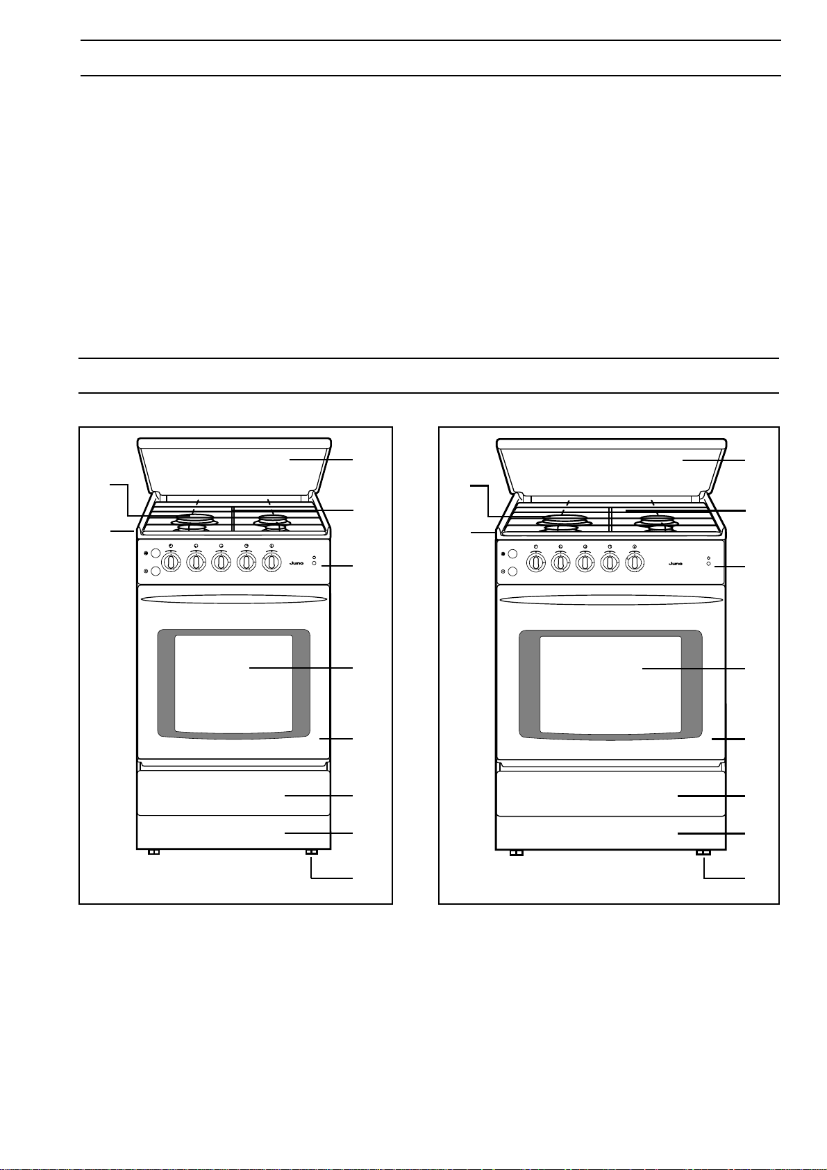
DESCRIPTION OF THE APPLIANCE
5
3
4
2
3
2
5
4
JGS 1000 - JGS 1010
JGS 3010 - JGS 5010
1
2
10
3
9
4
8
5
7
6
1
6
7
8
9
10
1
6
7
8
9
10
Fig. 1 Fig. 2
JGS 5110
1. Control panel
2. Hob unit
3. Open burner
4. Pot rest
5. Top lid
36
6. Oven
7. Oven door with window
8. Utensils drawer
9. Cover plate
10. Leveling leg
Page 4
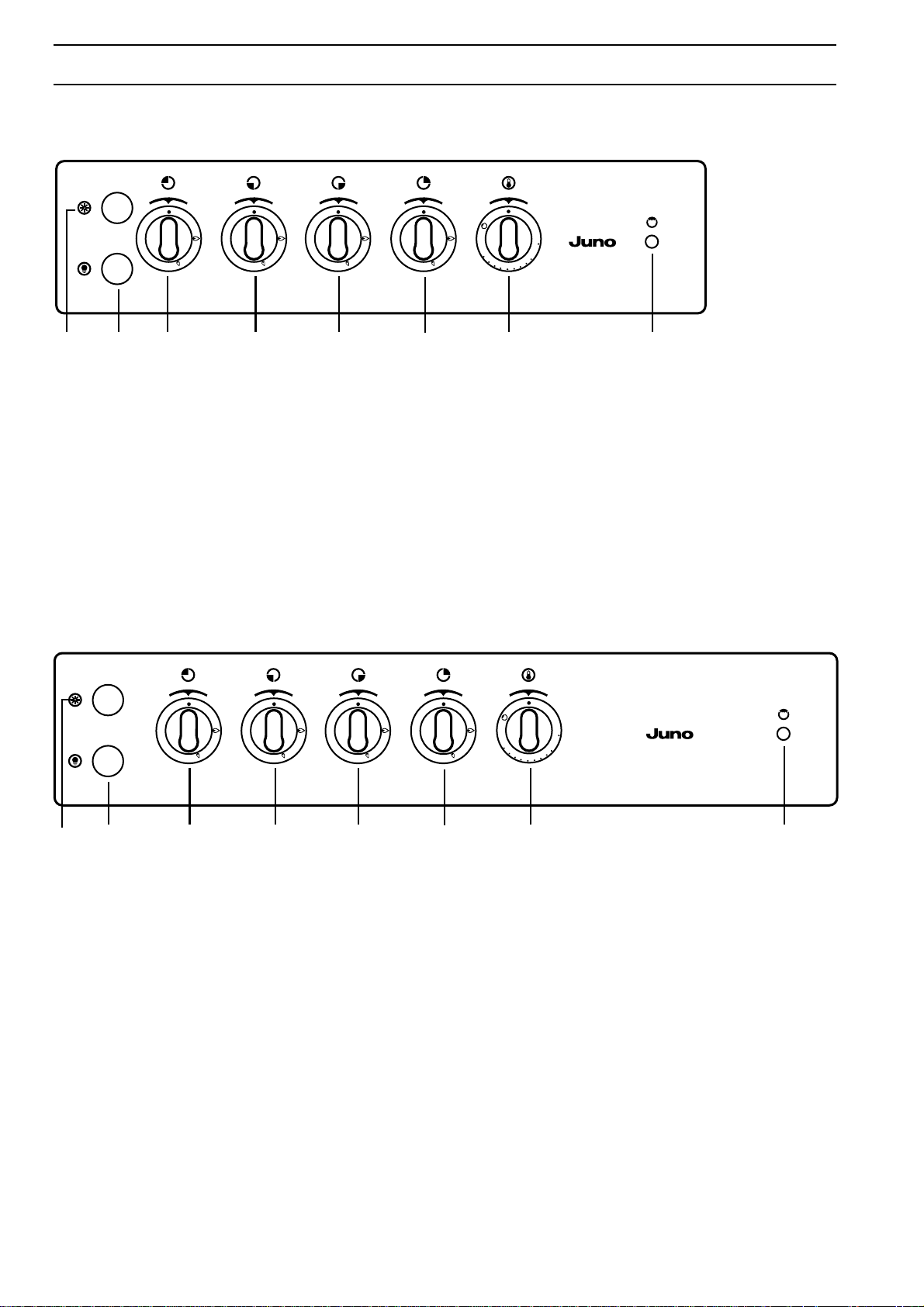
CONTROL PANEL
MOD. JGS 1000-1010-3010-5010
1
2
10
3
9
4
8
5
7
6
1234567 8
1. Electronic ignition of open burners and oven - with model JGS 5010, only
2. Oven light (except for models JGS 1000/1010)
3. Knob for rear left open burner - heavy-duty burner
4. Knob for front left open burner - standard burner
5. Knob for front right open burner - cooking burner
6. Knob for rear right open burner - standard burner (except for models JGS 1000)
7. Knob for oven burner (and electric grill in model JGS 5010)
8. Indicator lamp (with model JGS 5010, only)
Fig. 3
MOD. JGS 5110
1
2
10
3
9
4
8
5
7
6
1234567 8
Fig. 4
1. Electronic ignition of open burners and oven
2. Oven light
3. Knob for rear left open burner - heavy-duty burner
4. Knob for front left open burner - standard burner
5. Knob for front right open burner - cooking burner
6. Knob for rear right open burner - standard burner
7. Knob for oven burner
8. Indicator lamp
37
Page 5
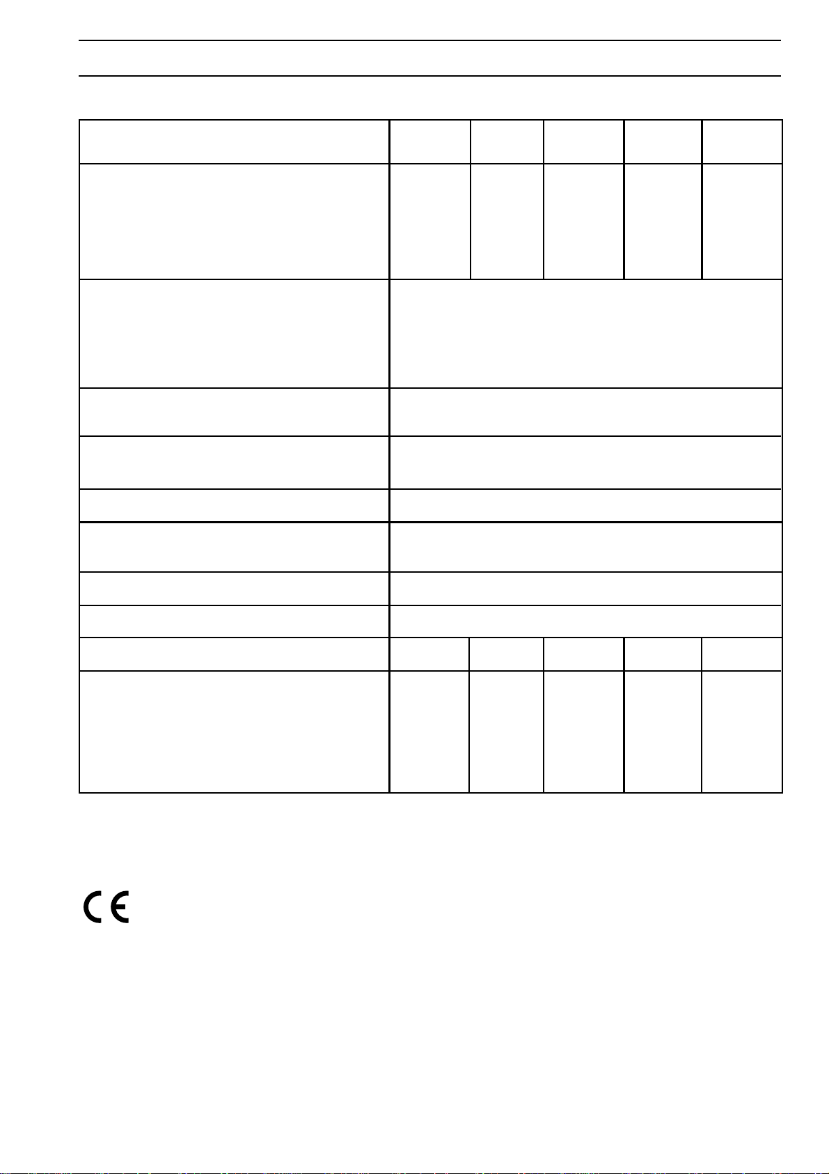
TECHNICAL DATA
MODELL JGS 1000 JGS 1010 JGS 3010 JGS 5010 JGS5110
Sizes: H = mm 850 850 850 850 850
W = mm 500 500 500 500 600
D = mm 600 600 600 600 600
with top lid closed H = mm 870 870 870 870 870
with top lid opened H = mm 1430 1430 1430 1430 1430
height adjustable by mm 15 15 15 15 15
Output of gas burners
Heavy-duty burner W 3000
Standard burner W 2000
Cooking burner W 1000
Oven burner W 3000
Operation Natural gas LPG
Maximum output Natural gas E 1.05 m3/h
LPG 800 g/h
Connection to gas supply R 1/2“
Nominal pressure Natural gas 20 mbar
LPG 50 mbar
Oven thermostat from 150°C to 260°C
Connection to the mains (50 cycles) 230 V
Output of electric grill kW - - - 1,8 1,8
Accessories Plate for Plate for Plate for Plate for Plate for
pastry pastry pastry pastry pastry
Pot rest Pot rest Pot rest Pot rest Pot rest
Protective Protective
screen for screen for
knobs knobs
The gas hob is registered acc. to German Standard DIN-DVGW.
CATEGORY II 2 ELL 3 B/P
This appliance corresponds to the
following
E.E.C. regulations:
- 73/23 - 90/683 (low voltage guideline):
- 89/336 (EMC guideline):
- 90/396 (gas guideline):
- 93/68 (general instructions):
and subsequent changes.
PRODUCER: ELECTROLUX HAUSGERÄTE
Rennbahnstraße 72-74
60528 Frankfurt
38
Page 6
INSTRUCTIONS FOR USE
OPEN BURNERS
● The open burners are thermoelectrically secured in
a way that the feed of gas will automatically be shut
off when the flame goes out.
● Lay the burner caps always exactly on the burner
chalice.
● The slots of the burner chalice must not be obstructed.
● The burner caps are enamelled
● Operate the open burners with items to be cooked
put on, only!
PUTTING INTO OPERATION
OF THE OPEN BURNERS
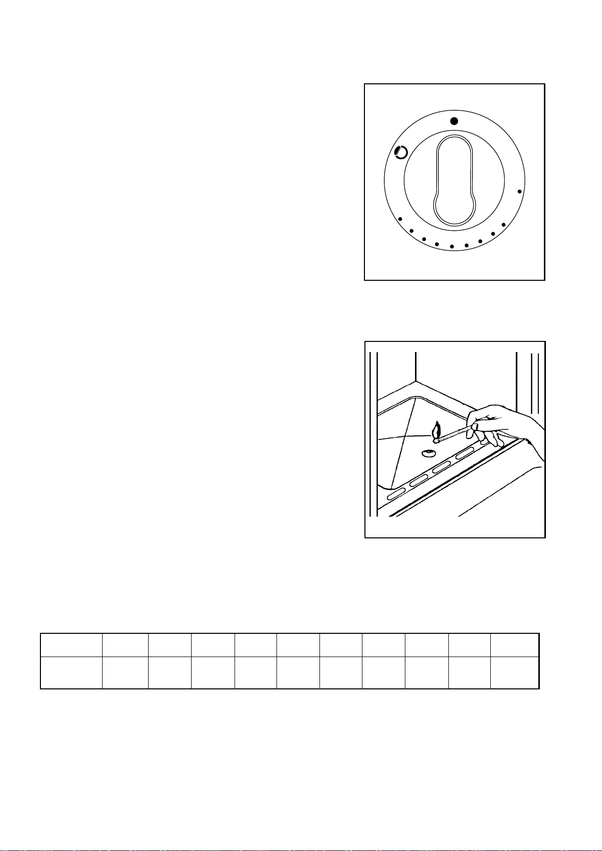
To ignite the gas burner bring a flame (matchstick,
lighter or igniter) to the desired burner, with that push
the corresponding rotary knob quite in and turn it
counterclockwise up to the position for maximum temperature. As soon as the burner is ignited, set the gas
flame as required.
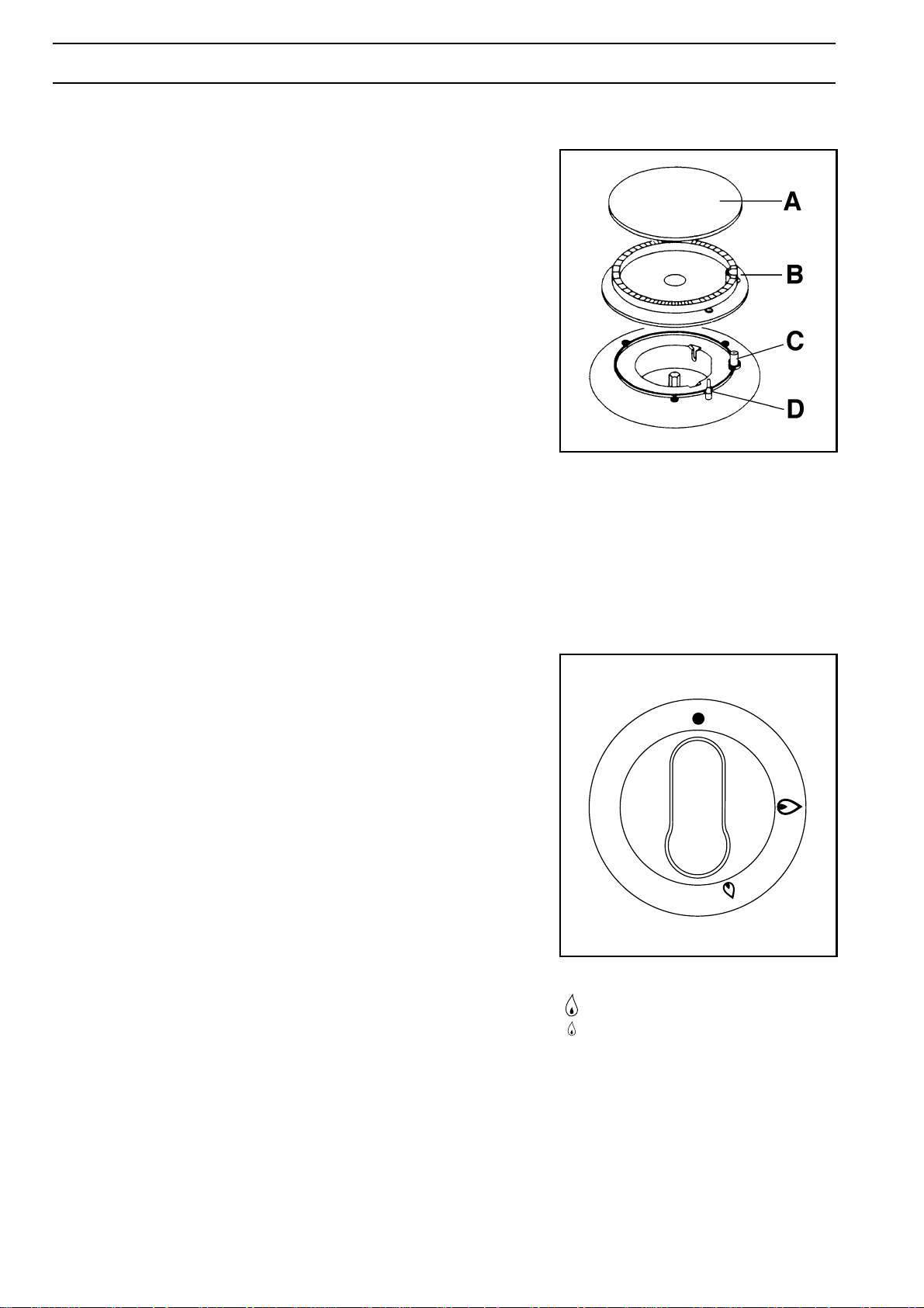
Fig. 5
FO 0204
Open burner
A Burner cap
B Flame distributor crown
C Spark plug
D Temperature sensor
In case of models with integrated automatic ignition
push the ignition button, which is marked by a small
spark symbol, at the same time quite push in the
corresponding rotary knob and turn it counterclockwise
up to the position for maximum temperature.
Because of pushing the ignition knob an ignition spark
will jump over to the burner and ignite it. After ignition of
the flame keep the rotary knob pushed in for about 5
seconds; this time is required to heat up the „temperature sensor“ (fig. 5, letter D) and to switch off the safety
valve, that otherwise would interrupt the feed of
gas. Afterwards check whether the flame is uniform and
turn the rotary knob to the desired strength.
In case the burner will in spite of several trials not ignite,
make sure that the flame distributor crown (fig. 5, letter
B) and the burner cap (fig. 5, letter A) are correctly laid
on.
To interrupt the gas feed turn turn the rotary knob in
clockwise direction up to position „●„.
When using fat or oil you must not leave it out of
visual control during the cooking procedure, as it
may flare up when being heated.
Fig. 6
●
Gas feed closed
High-burner
Low-burner
39
Page 7

COOKING ON THE OPEN BURNERS
PRESERVATION
When switching on the open burners for first-boiling/
frying, start at first with a big flame, and
afterwards set back to a small flame for cooking on. The
pot size must be chosen in a way that the flames will not
exceed the pot rim. You may use pots of at least 240 to
260 mm diameter with the
heavy-duty burner, pots of at least 200 to 220 mm
diameter with a standard burner, and pots of about 160
mm diameter and smaller with the auxiliary burner.
Always put the dishes in the middle of the open burner.
OVEN
● The oven burner is thermoelectrically secured in a
way that the feed of gas will automatically be cut off
if the flame goes out.
Most convenient is preserving in a water bath in a big
preserving pot on the heavy-duty burner.
Prepare the glasses in the usual manner. Make use of
commercial preserving glasses with rubber ring and
glass lid. Glasses with screw cap or bayonet catch and
metal boxes must not be used.
Put the glasses in the water bath, not, however, on the
pot bottom, but e.g. on a wire shelf. The glasses should
be about ∫ of the height in the water bath
Upon reaching the boiling of the water set the flame
smaller in a way that the water keeps on slightly boiling.
In preserving pots without a thermometer the firstboiling time is calculated from the start of boiling of the
water.
● The oven temperature is thermostatically controlled.
After ignition the oven burner performs with full
output until reaching the temperature set. Afterwards
the thermostat reduces the output to the value
required for keeping the temperature set.
● This control is effective with the door closed, only.
● The oven bottom can be removed for cleaning.
PRIOR TO FIRST USE
● Remove all accessories from the oven.
● Clean eneamel and glass surfaces with a wet cloth.
● After connection of the appliance operate the oven
for about 1 hour at max. temperature setting (see
paragraph: Putting into operation of the oven burner).
The smell resulting thereby will be safe if the room is
adequately ventilated.
● Afterwards wipe out the oven with a wet cloth and
dry.
40
Page 8
PUTTING INTO OPERATION
OF THE OVEN BURNER
● Attention! When operating the oven burner the
ceiling slide must be pushed in against stop.
● The oven burner is ignited with the door opened.
● Turn the oven control knob to the left in porition 10,
push in against stop, and ignite the gas flowing out.
After ignition keep the control knob pushed in for
about 5 more seconds until the temperature sensor
is sufficiently heated and the flame remains stable.
Afterwards the control knob can be set to the position
desired between 1 and 10.
● Watch the flame picture. If the flame goes out, repeat
the ignition procedure.
Models with integrated automatic ignition
● Push in the knob for oven/electric grill, turn from the
right to the left up to highest marking and keep the
knob pushed in.
● At the same time one pushes the button for the
electronic ignition in order to generate sparks. Keep
the knob pushed in until appearance of the flame
(one spark will be generated after each second).
● To switch off the burner turn the knob to position
„●„ (OFF)
Abb. 7
1
10
9
8
7
6
〈 Closed position (off)
1-10 Operating position of oven burner
2
3
4
5
Fig.. 8
TEMPERATURE SETTING
In correspondence with the items to be baked/roasted
and after ignition turn the oven knob to the required
temperature setting from 1 to 10
Position 1 2 3 4 5 6 7 8 9 10
Temperature
140°C 150°C 160°C 180°C 190°C 200°C 220°C 230°C 240°C 260°C
FO 1079
Ignition of the oven burner
41
Page 9

USE OF THE ELECTRIC GRILL
Attention:
● When using the electric grill the accessible parts
can be hot. Keep children off the appliance.
● The electric grill is used with half opened door.
The protective screen must also be installed.
To switch on the electric grill push in the oven control
knob and turn clockwise to marking .
When grilling direct on the wire shelf (grilling food), push
the fat collector into the rails under the grill.
INDICATOR LAMP FOR ELECTRIC GRILL
This lamp is located at the right of the control panel and
comes on when the electric grill is switched on.
In case of models with gas oven and during grill operation
leave the oven door open a crack and mount the
protective strip for the knobs (Fig. 8).
USE OF ACCESSORIES
The oven bottom sheet must always be pushed in
during operation.
The drip pan or the baking sheet must always be pushed
against the rear wall. With that the slots of the drip pan
must show to the rear.
Fig. 8
FO 2124
4
3
2
1
When roasting on the wire shelf insert the drip pan into
the lowest runner
42
Fig. 9
FO 0019
Details on the use of the runner levels are to
be taken from the baking/roasting chart.
Page 10

PREHEATING
If need be, preheat the oven acc. to the instructions in
the baking/roasting chart.
BAKING IN THE OVEN
Cakes on the baking sheet or in the drip pan are
baked on the middle shelf level, only. With that
always insert only one baking sheet.
Put cakes in a baking tin always on the wire shelf.
With that the baking tin should not protrude over the
rear rim of the wire shelf. Several baking tins can also
be put on the wire shelf. Dark tins are not
recommended; they absorb too much of the heat
radiated by the oven. Recommended are bright tins.
Prepare baked goods acc. to recipes. The temperature setting values, the shelf level as well as the
corresponding baking times required for the items to
be baked are to be taken from the baking chart.
Same refers to preheating requirements.
On principle the shorter duration of baking should
always be referred to. A cake baking too quickly from
top will not rise or collapse because of not enough
baking out of humidity.
Before switching off the oven stick a small wooden
rod into the baked goods. When pulling out again it
has to be dry and free from adhering traces of dough.
Turning over of the roast is only necessary when
roasting at higher temperatures.
The gravy ingredients for the perfection of taste such as chopped garlic, omions, roots, mush-rooms
or tomatoes, with lean meat also bacon and other fat
- are added into the drip pan with short roasting time
just in the beginning, and with longer roasting time
about during the last hour. Hot water (1/2 to 1 liter) is
added acc. to the desired degree of browning of the
roast and of the gravy ingredients. An earlier addition
of water will delay the effect of browning and the
gravy becomes too bright.
The temperature setting values required for the
individual roast are to be taken from the roasting
chart.
The roasting time is dependent on the size of the
meat. Considered in general are 12 - 15 min of
roasting time per centimeter height of meat.
By „spoon pressure“ you may check the state of
cooking of the roast; a well-done roast will resist to
the spoon pressure.
The meat juice of quite well-done meat is gray.
By measuring the core temperature inside the roast
by meanns of a commercial meat probe one may find
out when the meat roast will be ready. Dependent on
the sort of meat the core temperature can be taken
from the following chart.
With some dough remaining on the rod switch off the
oven and make use of the residual heat for about 5
minutes.
After the baking have the cake stand in the tin for 5 to
10 minutes. Afterwards loosen from the tin or from
the sheet and have it cool down on a cake grid.
Before making the first cut the items baked must be
quite cold.
ROASTING IN THE OVEN
An economical preparation is recommended only with
at least 1 kg of meat. Smaller roasts should then be
prepared on the open burner.
The meat must be well hung. Remove tendons, wash
and dry. Bones should be removed from roasts
before. This will reduce the roasting time and the
roast can better be carved. Only short before the
insertion of the roast salt and season, or brush it
about 10 minutes before the end of roasting time with
a pickle of water or oil, salt, paprica, pepper, etc.
Depending on the sort of meat the roast can be
prepared on the wire shelf, in the open (drip pan) or
closed vessel.
The prepared meat is placed on the wire shelf with
the „serving side“ or the fat side resp. to the top; the
crackling cut in squares. Lean meat is brushed with
oil or coated with slices of bacon.
The drip pan and the wire shelf with the meat are
together inserted into the oven.
MEAT ROAST CORE TEMPERATURE
Roast Core temp. at the
end of cooking in °C
Beef filet 45 - 55 English
Beef filet 55 - 65 pink
Beef filet 65 - 75 well-done
Beef roast 80 - 90 The lower core
temperature is
Pork roast 80 - 90 mainly chosen for
firm, juicy meat.
Spareribs 70 - 80 The higher core
temperature is
Roast veal 70 - 90 used for well-
cooked, dry meat
Roast lamb 70 - 85 and for roasts to
be well-cooked to
Roast venison 70 - 85 the inside.
Meat loaf 80 - 90
43
Page 11

POULTRY
Poultry is of high value for nutrition and taste. Preparation
is possible in a fresh or defrosted state. Carefully clean
the poultry, have it drip off and swob dry. Then salt inside
and season. Poultry can also be stuffed just as you like.
Poultry can be prepared in a big roasting vessel, on the
wire shelf, or direct in the drip pan. Have fat roasts cook
on the wire shelf in order to enable the fat to drip off. At
first pour about ˚ l of hot water into the drip pan. At the
end of the roasting time pour a little cold brine over the
roast at highest tempera
ture setting in order to obtain an especially crispy
surface.
GAME
Game is rich of valuable proteins, low-fat and easy to
digest. It stands for high contents of flavoring agents
which are providing the meat with the characteristic
nourishing flavour. Game must be well hung. Deepfrozen pieces of roasts are to be defrosted before
preparation.
Carefully remove the skin from the meat and the tendons.
Remove the fat as it gives off an unpleasant taste. In
particular with roasts of
venison and wild boar. Quickly wash the meat, or wipe
off with a wet cloth, and dry. Only short before roasting
rub salt and spices into the meat. Coat the meat with
slices of bacon or lard.
The meat becomes more tender as a result of laying it
2-3 days before the preparation in a pickle or marinade.
Game is at best to be roasted in a closed vessel in order
to keep it most juicy. When roasting in the drip pan rinse
same at first with water and, if need be, lay out with
stripes of bacon. Loosely
cover the prepared roast with an aluminium foil and fix
it on the rim.
Too high temperatures are unfavourable as the meat
will dry out easily.
HINT
Recipe data as well as hints on the preparation for
boiling, baking and roasting are furthermore to be taken
from cooking and recipe literature as available from
specialist dealers.
PRESERVING IN THE OVEN
● Up to 6 preserving jars of 1 to 1.5 l capacity can be
prepared in the oven.
● As usual prepare the items to be preserved and the
jars.
● Exclusively make use of commercial jars with heatresistant rubber rings. Glasses with screw cap or
bayonet catch and metal boxes must not be used.
● Insert the drip pan into the first shelf level from the
bottom. Put the prepared jars in the drip pan. The
glasses must not touch each other and should be
filled to possibly the same height and with the same
contents and be clamped together. Fill the drip pan
to the half with hot water. Set the temperature control
knob to position 2 or 3.
● Watch the items to be preserved until the liquid in the
glasses will start to pearl (after about 40 - 50 min with
1 l-glasses, after about 60 min with 11/2 l-glasses).
● In case of fruits and pickled gherkins then switch off
the oven, but have the glasses stand in the closed
oven for about 30 more minutes (about 15 more
minutes with delicate fruits, such as strawberries,
about 15-40 more minutes with stone and core fruits)
● In case of vegetable or meat resp. and after reaching
the state of pearling, accordingly set back the temperature and have the jars remain in the closed oven for
about 30 more minutes.
● Then remove the jars at once. Do avoid a slow
cooling down in the oven, as this would support
another new formation of germs.
44
Put the jars on an absorbent cloth, cover them and
protect against draught.
Page 12

CHART ON BAKING / ROASTING / GRILLING
Dishes Weight (g) Shelf level Height Pre-heating Temperature Time
from below setting °C °C (min.)
BAKING
Pastries in moulds
High ring cake 1500 3 yes 170° (3) 60 - 70
Marble cake 1500 3 yes 170° (3) 60 - 70
Cake in oblong tin 1000 3 yes 170° (3) 60 - 70
Cheese cake 1500 3 yes 170° (3) 60 - 70
Sponge cake 750 3 yes 160° (2) 35 - 45
Tart base, stirred dough 750 3 yes 170° (3) 20 - 30
Pastries on baking sheets
Rye bread 1000 3 yes 180° (4) 60 - 70
Yeast plaited loaf 1000 3 yes 170° (3) 35 - 45
´Strudel´ 500 3 yes 170° (3) 50 - 60
Yeast cake with dry topping 750 4 yes 160° (2) 30 - 35
Yeast cake with wet topping 1000 3 yes 160° (2) 45 - 50
Swiss roll 400 3 yes 160° (2) 10 - 15
Small pastries (stirred dough) 300 3 yes 160° (2) 12 - 18
Small pastries (puff paste) 500 4 yes 160° (2) 20 - 30
Rolls 500 4 yes 180° (4) 15 - 25
Cream buns / éclairs 300 4 yes 180° (4) 20 - 30
ROASTING
Meat
Roast pork 1000 3 - 175° (3) 90 - 120
Roastbeef 1000 3 yes 190° (5) 45 - 60
Roast veal, abt. 1 kg 1000 3 - 190° (5) 60 - 90
Poultry
Chicken 1000 3 - 190° (5) 60 - 90
Duck 1700 3 - 190° (5) 120 - 180
Goose 3000 2 or 3 - 180° (4) 150 - 210
Fish
Whole fish (mackerels, etc.) 1000 3 - 185° (4) 40 - 50
Soufflés and gratins
Vegetable soufflé 500 3 - 185 ° (4) 40 - 50
Noodle soufflé 1000 3 yes 205° (6) 40 - 50
Vegetable gratinated 500 3 yes 190° (5) 30 - 40
Dishes Oven switch Shelf level height Grilling time
from below
Pork cutlet 4 10 min per Side
Beef cutlet 3 20 min per Side
Merguez-sausages 4 10 - 15 min
Fish 3 - 4
Chicken portions 3 20 min per Side
10 - 15 min acc. to size or thickness
Hot dishes 3 5 - 10 min
Farinaceous products gratinated 3 5 - 10 min
Fancy meringue 3 5 min
Hot toast with bacon and cheese
Roasted pudding
4 5 min
3 5 min
45
Page 13

CLEANING AND CARE
- For cleaning do not make use of scouring agents,
caustic cleaners and hard objects.
- Do not scratch off burnt-in residues, instead soak them
with a wet cloth or with hot water resp. and remove with
a little cleanser additives.
OPEN BURNERS
For the cleaning of pot rests, hob unit and open burner
sections use hot water with a little cleanser additive;
also clean the temperature sensor with a small soft
brush.
The slots of the burner chalice must be kept clean, too.
Relocate the burner parts correctly. Not correctly
positioned burner caps will make ignition more difficult.
After cleaning do well dry the open burner.
OVEN
FO 0416
Fig. 10
The still warm oven is to be cleaned after every use with
hot water with a little cleanser additive! For better
cleaning of the oven the bottom slide can be removed.
When cleaning make sure that spray will not be sprayed
on the temperature sensor located at the oven ceiling.
Never clean the oven burner by yourself. Have this
cleaning work exclusively be carried out by an expert
fitter. This procedure is only needed where the flames
will not burn at all gas outlets.
After cleaning re-install the bottom slide!
OVEN DOOR REMOVAL
The door can be removed for more efficient cleaning.
Attention! Careless use of the oven will result in
danger of hurts in the area of the door hinges!
Unhooking of the oven door
- Fold the door down in horizontal position.
- Door catches on both sides to be clockwise turned by
30 degrees by means of a screwdriver.
- Slightly lift the door and remove.
Fig. 11
FO 0417
Reinsertion of the oven door
- When re-installing the door lift the lower hinge frame
and on both sides introduce into the openings
provided at the cooker.
- Turn back the door catches.
46
Fig. 12
FO 0967
Page 14

TOP LID REMOVAL AND REINSERTION
For better cleaning the top lid can be removed.
- For removal fold up the lid and remove upward.
- For reinsertion of the lid introduce the pivot pins
vertically into the pin guide.
OVEN LAMP
Prior to replacement the cooker must be
separated from the mains by unscrewing the
fuses or switching off the circuit-breaker!
Unscrew the glass cover in anticlockwise direction and
replace the bulb (socket E 14, 230V, 25 W, 300°C).
Afterwards screw down the glass cover again.
The replacement of the oven lamp is not covered by the
guarantee.
REPLACEMENT OF COOKER
COMPONENTS
In case of damage the customer must replace only parts
removable without the use of tools. The replacement of
parts to be removed with tools must exclusively be
carried out by an approved electrician or gas fitter resp.
● The control knobs for open burners and oven can be
drawn off to the front.
Fig. 13
Fig. 14
FO 0418
FO 0424
● Spareparts can be ordered with the after-salesservice under indication of ordering number and
model name of the appliance
● Trouble
In case of trouble with the gas section or when
smelling gas resp. do at once:
- close the gas tap of the gas feed or direct
at the bottle resp.!
- extinguish the gas burners or all flames
resp., and cigarettes!
- do not switch on any electrical appliance!
- ventilate the room!
- inform the gas fitter!
47
Page 15

MONTAGEANWEISUNG
IMPORTANT HINTS
● The connection of the gas cooker must exclusively
be carried out by an approved gas fitter. This must
happen under adherence to DVGW/ÖVGW
regulations, technical rules, guidelines of federal
building regulations, guidelines and regulations of
gas supply boards as well as to the following
standards:
- DVGW, worksheet G600 (DVGW-TRG, 1986)
- Technical rules for gas installation
- TRF 1988 - Technical rules for LPG
● Prior to installation one must check whether the
indications on the typeplate are in conformity with
the local gas conditions.
● The gas connection must be accessible and provided
with a shutoff device.
● Prior to any action stop the feed of gas to the cooker
● The minimum distance between gas cooker and
cooker hood must correspond to the instructions
given by the manufacturer of the hood.
● Prior to the opening or exposure of live parts the gas
cooker must be made dead! Remove fuses or activate
the earthing-pin plug.
Gas
connection
Gas
connection
Fig. 15
FACTORY-SIDED SETTING
● The gas cooker is tested and registered acc. to
German Standard DIN-DVGW.
● The gas cooker is supplied with the sealed gas
setting to natural gas, towns gas, or LPG and
accordingly marked with a label.
● All gas burners are thermoelectrically secured in a
way that the feed of gas will automatically be shut off
when the flame goes out.
● The indications are given on the typeplate of the
cooker. The typeplate is visible after door opening.
● The load and the throughput of gas of the individual
burners are to be seen in chart I.
● A replacement of jets is required for the conversion
to a different type of gas. The indications are given in
chart II to VII.
● With conversion to a different type of gas, with
repairs, or with a damaged sealing (only with natural
gas E 15), the functional parts must be checked acc.
to installation instructions and sealed again.
Functional parts are: high-burner jet, low-burner jet
and for the oven in addition the primary air focusing
sleeve.
Fig. 16
FO 0994
115
400
780
48
Page 16

GAS COOKER INSTALLATION
When installing the gas cooker a safety distance of 15
mm must be kept towards the adjacent furniture. If this
safety distance cannot be kept, a thermal insulation will
have to be located between the side panels and the
furniture.
Align the gas cooker horizontally. For that do horizontally
align the open burners by means of the set screws
mounted in the base and adapt the upper edge of
cooker to the adjacent furniture.
GAS CONNECTION
On the back side (left and right) the cooker is provided
with two gas sockets R 1/2“.
The gas connection must be accessible and provided
with a shutoff device.
Recommended is a safety gas socket. Same should be
located at the right or left, outside the radiation area. The
connection can be carried out rigid or by the use of a
DVGW-approved safety gas hose with socket acc. to
DIN 3383, page 1. In case the gas connection is not to
be carried out at the side prepared, but instead at the
other side, the closure will have to be loosened and
attached on the other side. Always insert a sealing
washer. Afterwards connect to the gas supply at the free
side.
When using the safety gas hose make sure that same is
not guided through hot zones, but freely installed.
After connection subject cooker and connection to a
sealing test.
PUTTING INTO OPERATION
Fig. 17
Fig. 18
FO 0063
A
FO 0605
A Ramp end piece
B Round disk
C Ramp closure
A
B
C
Putting into operation to be carried out acc. to instructions
for use.
Ignite each open burner and check the burning stability
of high-burner and low-burner setting. (see par.: open
burner setting).
Heat up the oven burner for at least 10 minutes at
highest temperature setting. Then turn the oven control
knob to position 1. The burner must burn with a little, but
stable flame (see par.: oven burner setting).
After inspection: user to be instructed, function and
operation to be explained, instructions for use to be
handed over.
49
Page 17

CONNECTION TO THE MAINS
The appliance is designed for the operation with a onephase supply voltage of 230 V.
The electrical connection must be carried out acc. to the
valid standards and the relevant legal prescriptions.
Before the execution of the electrical connection make
sure that
- fuselage and house installation are designed for the
max. load of the appliance (see typeplate);
- the house installation is provided with a correct earthing
that will also correspond to valid standards; socket and two-pole switch will also be easily accessible
if the appliance is switched on.
The connection must be carried out direct, i.e. without
plug connection. For that there must be provided between
appliance and power supply a two-pole switch with a
gap of at least 3 mm between the contacts, which is
designed for the load of the appliance and corresponding
with the valid standards. The yellow-green earthing
cable must, however, not be interrupted by a switch.
The brown phase cable (starting at terminal „L“ on the
terminal board of the cooker) must always be connected
to the power supply phase line. The power supply cable
is to be installed in a way that no position will reach a
temperature exceeding 50°C above room temperature.
If there is need to replace the power supply cable, do
please make use of cable type H05RR-F with a crosssection designed for the load of the appliance. The little
yellow-green earthing cable must be longer by about 2
cm than the phase cable and the neutral conductor (fig.
19).
After completion of the electrical connection check all
heating elements by switching them on for about 3
minutes.
The producer rejects any liability for the case that
the afore-mentioned measures for the prevention of
accidents will not be complied with.
Phase
earthing cable (yellowgreen)
Fig . 19
50
Page 18

CONVERSION TO OTHER TYPE OF GAS
When converting to a different type of gas there is need
for an additional setting of the amount of gas or for a
replacement of jets resp. (see charts I to VII).
CONNECTION TO LPG
A metallically sealed connection piece 8 x 1 mm must be
fitted to the R 1/2“ gas supply socket. When doing so
please focus on leakage testing .
REPLACEMENT OF OPEN BURNER
HIGH-BURNER JETS
- Remove pot rest, burner cap and burner chalice.
- By means of a wrench replace the high-burner jets
acc. to indications and descriptions in charts I to VII.
CONVERSION OR REPLACEMENT
OF LOW-BURNER JET
- Remove pot rests, hob unit covers and burner
chalices.
- Loosen the fastening screws of the hob unit and
remove.
- Loosen the 3 each visible fastening screws of the
open burners. Remove the hob unit.
- Draw off the control knobs to the front.
- Unscrew the fastening screws of the control panel.
- Set or replace resp. the low-burner jet acc. to charts
I to VII.
- Re-install in reverse sequence.
Fig. 20
Fig. 21
FO 0392
FO 0069
low-burner jet
FO 0068
Fig. 22
51
Page 19

REPLACEMENT OF OVEN JET
- Pull out the oven bottom sheet.
- Unscrew the fastening screw and remove the oven
burner
- Turn out the burner jet and insert the jet suitable for
the new type of gas acc. to charts
I to VII.
- Re-install in reverse sequence.
oven burner
OVEN TEMPERATURE CONTROL
Instructions for the adjustment of the by-pass needle
of the oven burner thermostat.
The adjustment of the round head by-pass needle for
models provided with this feature, is carried out as
follows:
- Remove the selector switch;
- Take away the control panel;
- Carry out the adjustment by means of a fine-edged
screwdriver, refer to the figure.
- At first check, whether a quick turning of the tap from
maximum flame to minimum flame would result in
extinguishing the flame.
PERFORMANCE TEST
Carry out a performance test after conversion of the jets
and after maintenance and repair work:
- In accordance with the instructions for use put the
appliance into operation.
- Carry out a sealing test acc. to DVGW-TRGI or TRF
resp.
- In cold and warm state check the burning safety of all
burners.
Fig. 23
Fig. 24
Fig. 25
FO 1132
fastening
screw
FO 1072
oven burner jet
FO 0112
INFORMATION OF THE USER
- Make the user familiar with the operation of the
appliance.
- In particular refer to the fact that structural changes,
which may affect the supply of combustion air, will
have need for a nother performance test.
GREASING OF THE TAPS
If after longer use the taps cannot be actuated at ease,
the sliding faces will have to be greased. Proceed as
follows:
- Shut off the gas supply.
- Put the control knobs in 0-position and pull off.
- Remove the control panel.
- Dismantle the tap caps and pull off the plugs of the
tap.
- Clean and regrease the sealing faces. The tap
grease must be applied very thin, only.
low-burner jet
Fig. 26
Attention!
Never interchange tap housing and plug as otherwise
there will be no guarantee for sealing.
FO 0392
52
Page 20

THERMAL LOAD, THROUGHPUT OF GAS, MARKING OF JETS
Chart I
Cooker setting Burner spot Auxiliary burner Standard burner Heavy-duty Oven burner
burner
high low high low high low high low
Natural gas "E" Thermal load kW 1 0,33 2 0,45 3 0,65 3 0,85
20 mbar
H5 = 37,78 MJ/m3Throughput of gas l/h 95 31 190 43 286 62 286 81
W5 = 50,72 MJ/m
Natural gas "LL" Thermal load kW 1 0,33 2 0,45 3 0,65 3 0,85
20 mbar
H5 = 32,49 MJ/m3Throughput of gas l/h 111 36 221 50 332 72 332 94
W5 = 41,52 MJ/m
LPG Thermal load kW 1 0,33 2 0,45 3 0,65 3 0,85
50 mbar
H5 = 125,81 MJ/m3Throughput of gas l/h 73 24 145 33 218 47 218 62
W5 = 87,33 MJ/m
3
Marking of jets 70 E 96 E 119 E 116 E
3
Marking of jets 74 E 106 E 133 E 128 E
3
Marking of jets 43 23 60 28 75 35 76 40
The term „marking of jets“ is referring to the jet diameter in hundredth of mm. In case of jets marked with
„E“ the nominal values for thermal load and for throughput of gas are achieved by the setting of jets.
CONVERSION TO OTHER TYPE OF GAS
Chart II
Conversion from natural gas E to ...
Open burners
High-burner Low-burner
NATURAL GAS LL Unscrew high-burner jet (fig. 20) and screw No conversion
down the jet for gas LL acc. to chart I
LPG Unscrew high-burner jet (fig. 20) and screw Unscrew low-burner jet (fig. 22) and acc. to chart I
down the jet for LPG acc. to chart I. screw down the setting jet for LPG until stop .
With conversion to a different type of gas fix a corresponding label!
53
Page 21

Conversion from natural gas E to ...
Oven burners
High-burner Low-burner Primary air
NATURAL GAS LL Unscrew high-burner jet (fig. 23, 24, No conversion
25) and screw down the jet for gas
LL acc. to chart I.
Chart III
LPG Unscrew high-burner jet (fig. 23, 24, Unscrew low-burner jet (fig. 26)
No conversion
25) and screw down the jet for LPG and acc. to chart I screw down
acc. to chart I. the setting jet for LPG until stop.
Conversion from LPG to ...
Chart IV
Open burners
High-burner Low-burner
NATURAL GAS E Unscrew high-burner jet (fig. 20) Unscrew low-burner jet (fig. 22)
and screw down the jet for natural gas and acc. to chart I screw down
LL acc. to chart I. the jet for natural gas E until stop.
NATURAL GAS LL Unscrew high-burner jet (fig. 20) Unscrew low-burner jet (fig. 22)
and screw down the jet for natural gas and acc. to chart I screw down
LL acc. to chart I. the jet for natural gas LL until stop.
With conversion to a different type of gas fix a corresponding label.
When setting to natural gas E the high-burner fixed jet, the low-burner setting jet as well as the primary air setting
sleeve will have to be sealed-in again.
Conversion from LPG to ...
Chart V
Oven burners
High-burner Low-burner Primary air
NATURAL GAS Unscrew high-burner jet (fig. 23, 24, Unscrew low-burner jet (fig. 26)
E 25) and screw down the jet for natural and acc. to chart I screw down
gas E acc. to chart I. the setting jet for natural gas E
until stop.
NATURAL GAS Unscrew high-burner jet (fig. 23, 24, Unscrew low-burner jet (fig. 26) No conversion
LL 25) and screw down the jet for natural and acc. to chart I screw down
gas LL acc. to chart I. fthe setting jet for natural gas LL
until stop.
With conversion to a different type of gas fix a corresponding label.
When setting to natural gas E the high-burner fixed jet, the low-burner setting jet as well as the primary air setting
sleeve will have to be sealed-in again.
54
Page 22

Conversion from natural gas LL to ...
Open burners
High-burner Low-burner
NATURAL GAS E Unscrew high-burner jet (fig. 20)
and screw down the jet for natural gas No conversion
E acc. to chart I.
LPG Unscrew high-burner jet (fig. 20) Unscrew low-burner jet (fig. 22)
and screw down the jet for LPG and acc. to chart I screw down
acc. to chart I. the setting jet for LPG until stop.
With conversion to a different type of gas fix a corresponding label!
Chart VI
Conversion from natural gas LL to ...
Oven burners
High-burner Low-burner Primary air
NATURAL GAS E Unscrew high-burner jet (fig. 23, 24, No conversion
25) and screw down the jet for gas
E acc. to chart I.
LPG Unscrew high-burner jet (fig. 23, 24, Unscrew low-burner jet (fig. 26)
25) and screw down the jet for LPG and acc. to chart I screw down
acc. to chart I. the setting jet for LPG until stop.
Chart VII
No conversion
55
Page 23

WHAT TO DO, IF ...
To file an after-sales-service call is not always necessary. In some cases you may cure the problem by yourself.
For this purpose please find some hints below.
Important! Repair work must exclusively be carried out by experts. Inappropriate repairs may result in
considerable danger for the user.
What is, ... Possible cause Remedy
... if a liquid or a highly liquid dough is Appliance not horizontally installed. Align the appliance by means of the
distribuited rather unilaterally? adjustable legs located underneath or check
... if the open burners are irregularly burning Flame picture irregular due to wrong gas Have the gas setting checked.
after installation of the appliance? setting
... if the flame picture of the open burners has Wrongly laid on burner parts. Correctly put the removable burner parts in
changed all of a sudden? place.
... if a cake or pastry gets dark underneath? Baking sheet too close to oven bottom. Insert cake or pastry in a higher shelf level of
wrong shelf level. Or too high temperature. the oven.
the installation.
... if the baking result is not satisfactory? Wrong oven setting. Carry out the oven setting acc. to the baking
... if smoke develops when roasting? Oven temperature too high Set a lower roasting temperature.
Distance not enough between grill element Increase the distance between grill element
and items to be grilled and items to be grilled
... if the oven is heavily soiled during roasting? Oven temperature too high Set a lower roasting temperature.
Wire shelf and drip pan wrongly inserted. Put the wire shelf above the drip pan and
... if the oven burner is continuously going out Wrong gas setting. Have the gas setting checked by the
after installation of the appliance? appliance installer.
... if the oven burner gies out all of a sudden? Quick closing of the oven door (resulting air Slowly close the oven door if the oven is
pressure) in operation.
... if oven door glass pane or window is Waste air opening covered Do not cover the waste air opening by pots,
steamed-up during heating up? pot cloth, etc.
... if oven door must be pushed? Normal appearance, is due to existing Not possible, adequacy will not be impaired.
difference in temperature.
... if the flame goes out after ignition of the Pushed too shortly Knob to be pushed longer
burners?
Pushed not strong enough Knob to be pushed strongly prior to release.
... if the cake gets too bright underneath? Wrong shelf level. Insert the cake in a lower level.
indications given in recipe booklets or in
charts.
insert together in one shelf level.
... if the cake gets too dry? Roasting temperature too low. Slightly increase the roasting temperature.
Baking time too long. Select a shorter baking time.
... if the cake is slippery, doughy inside or Baking or roasting temperature too high. Set baking or roasting temperature slightly
if the meat will not get cooked inside? lower.
Baking or roasting temperature too short. Select a longer baking or roasting time,
Too much liquid in the cake dough. Put less liquid in the cake dough.
Note:
Baking or roasting times cannot be reduced
by higher setting of the oven temperature
(outside cooked, inside raw)
have the dough rise longer
56
Page 24

SERVICE AND SPAREPARTS
The gas cocks must be periodically lubricated to
ensure good working and safety.
Maintenance should be performed as follows:
● Remove the knob and panel after having taken out
fastening screws.
● Loosen the two screws located at the sides of the
cock bar.
● Remove the cone and clean it carefully.
● Then, apply a thin layer of grease non soluble in
water, suitable for gas cocks. Take care not to
obstruct the gas flow holes by an excess of grease.
Reassemble the whole with utmost care performing the
operations described above inversely.
ORIGINAL SPARE PARTS
This machine, before leaving the factory, has been
tested and studied by many experts and specialists, in
order to give you the best results.
Any repair work which needs to be carried out should
be done with the utmost care and attention.
For this reason we reccomend that for any problem you
contact the dealer who sold it to you, or our nearest
authorized Service Centre, specifying the nature of the
problem and the particular model which you own.
Original spareparts, certified by the product manufacturer
and carrying this symbol
are only available at our Service Centre and authorized
spareparts shops.
57
 Loading...