

Page 1

INSTRUCTIONS FOR INSTALLATION AND USE
MONTAGE- UND GEBRAUCHSANWEISUNG
INSTRUCTIONS POUR L'INSTALLATION ET L’UTILISATION
ISTRUZIONI PER L'INSTALLAZIONE E L’USO
INSTRUCCIONES PARA INSTALACIÓN Y USO
INSTRUÇÕES DE INSTALAÇÃO Y UTILIZAÇÃO
AANWIJZING VOOR GEBRUIK EN INSTALLATIE
Page 2
ENGLISH
DESCRIPTION
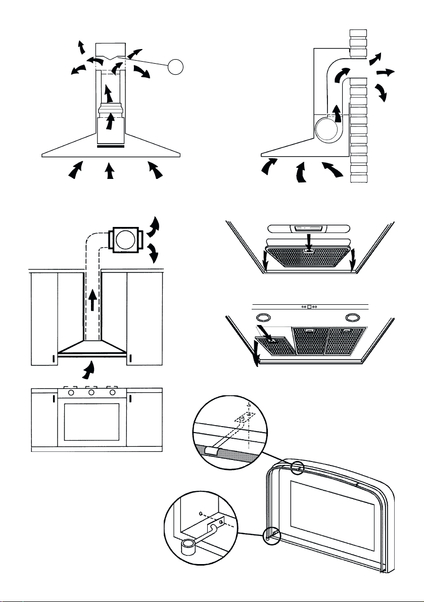
The unit can be found in filtering hoods, exhaust hoods or in hoods with an outside motor. In the Filtering hoods (Fig. 1)
the air and steam taken up by the unit are purified with carbon filters and returned to the environment through the aeration
grids on the side of the flue. WARNING: When using filtering hoods, both carbon filters and an air deflector must be used.
Located in the upper part of the pipe, this deflector recycles the air to the environment (Fig. 1A). In the Exhaust hoods (Fig
.2) an exhaust duct conveys the steam and cooking odors directly outside through the wall/ceiling. Therefore they do not
require carbon filters. In the hoods with an outside motor (Fig. 3), a vacuum suction unit must be connected; this exhaust
will operate separately, conveying the exhaust air through the unit. Only use vacuum units suggested in the original
catalogue.
INSTALLATION
To facilitate installation, before starting remove the grease filter/s: press inward on the clamp at the handle and pull the
filter downward (Fig. 4/5).
Installation of a utensil holder (upon request): See Figure 6A or 6B depending on the model purchased. Install the utensil
holder with 4 flathead screws (supplied). Secure the 2 supports (C) to the hood, one on the left and one on the right; insert
the utensil holder into these supports. Keep a good grip on it until you have installed, and secured, at least one of the 2
supports (D) at the top of the hood.
Installation on the wall (Fig. 7): Using the special drilling template, drill the required holes in the wall. As previously
specified in the chapter “Warning” remember there must be a minimum of 650 mm between the bottom edge of the hood
and the stop of the stove. Secure the metal bracket (B) to the wall using the screws and plugs (bracket, screws and plugs
are all supplied with the unit). Use the 2 triangles cut into the bracket to position it precisely along the vertical axis of the
hood. Then set the hood onto the bracket. Adjust the horizontal position, shifting the hood to the right or left as needed
lining it up with the wall units. If the height of the hood also requires adjustment, use the special regulation screws (V)
(supplied). Once regulation has been completed, finish securing the hood with 4 more screws (M): mark the points for the
4 holes on the wall, remove the hood and drill (8mm diameter holes); then use the plugs and screws to complete installation.
Installation with rear panel (Fig. 8): The rear panel is positioned at the top of the stove, flush against the wall. Rest the
lower edge of the panel behind the stove and anchor the upper edge to the wall using the two holes found on the panel.
Insert the screws and plugs provided (A). The unit is secured to the rear panel as though it were being installed on the wall:
use the supplied metal bracket (B) and the screws and plugs supplied with the panel.
Securing the extension pipes:
by the decorative piping. – If your unit is installed in an Exhaust hood or in a hood with outside motor, prepare the air exhaust
hole.
When installing exhaust hoods and hoods with outside motor, to achieve the best possible conditions use an air exhaust
pipe that : i) is as short as possible, ii) has a minimum of curves (maximum angle: 90°), iii) is made of a material that
complies with the standards (which vary from nation to nation) and iv) is smooth on the inside. It is also advisable to avoid
any drastic changes in pipe section (diameter: 150 mm).
Adjust the width of the extension pipe support bracket (W) using screws A indicated in Fig. 9. Then use the plugs and
screws provided to secure it to the ceiling. Make certain it is aligned with the hood. For filtering hoods, the air exhaust grids
are positioned in the upper part (Fig. 10). For exhaust hoods, turn the upper pipe over so that the air exhaust grid is in the
lower section (Fig. 11).
Be very careful when handling the telescopic pipes, especially when resting these on the hood body, to
prevent scratching.
Exhaust hoods and hoods with outside motors: Connect the hood flange to the exhaust hole in the wall/ceiling using a
flexible pipe. Only for models with outside motor (Fig. 12): plug the hood into the outside control unit using the special
terminal block: remove wire clamp A and lid B from the wiring junction box. Secure the wire connecting the control unit
to terminal C. Then replace wire clamp A and lid B on the wiring junction box. The other end of the wire is secured to the
terminal block on the outside control unit. Plug in the hood. Insert the extension pipes setting them on the hood; extend
the upper pipe to the ceiling and secure with the 2 screws (G) - Fig. 13.
Filtering hood: Secure the deflector to the upper pipe using the 4 special screws (provided) – Fig. 14; hook up the flexible
pipe (diameter: 125) to the deflector. Install the reduction (provided) on the hood air outlet point (Fig. 15). Take the 2
assembled extension pipes and set them on the hood; extend the upper pipe to the ceiling and secure with the 2 screws
(G) - Fig. 13. Extend the lower pipe taping it in place and then connect the flexible pipe to the hood reduction. Plug in the
hood. Extend the lower pipe downward setting it against the hood. Install the carbon filters by pressing the 2 tabs on the
filter down into the special housing (Fig. 16) and rotating upward.
Basic installation requirements: – Set the electrical power supply within the space covered
OPERATION
Depending on the model, the unit is equipped with the following commands:
Commands shown in Fig. 17: Button A = turns the lights on/off. Button B = turns the TIMER on/off: press once to turn
the timer on, therefore, after 5 minutes, the motor cuts out (at the same time the selected speed blinks on the display); the
timer remains on if the motor speed is changed. Display C = - indicates the selected motor speed (from 1 to 4); - indicates
Timer On when the number blinks; - indicates Filter Alarm when the central segments is on or blinking.
Page 3

Button D = makes the motor work (at the last speed selected); pushing the button again, the speeds of the motor are
sequentially selected from 1 to 4; keeping this button pressed for about 2 seconds shuts down the motor.
Button R = resets the grease filters or carbon filters; when the filter alarm appears (i.e. when the central segment on the
display goes on), the grease filters must be cleaned (30 hours of operation); when the central segment starts blinking, the
grease filters must be cleaned and the carbon filters replaced (120 hours of operation). Obviously, if the hood is not a
filtering model and does not have a carbon filter, clean the grease filters both when the central segment goes on and when
it starts blinking. The filter alarm can be seen when the motor is off and for about 30 seconds. To reset the hour counter,
keep the button pressed for 2 seconds while the alarm can be seen.
Commands shown in Fig. 18/19: Switch A: LIGHT; position 0: light off; position 1: light on. Switch B: MOTOR SPEED:
makes it possible to select the motor operating speed; position 0: motor off. C : Motor on light.
Commands shown in Fig. 20: A = light switch. B = first speed motor ON/OFF switch. C = second speed switch.
D = third speed switch. E = motor on light.
Pay special attention to the grease filters:
must be cleaned approximately once every 30 hours of operation (when the central segment on the display goes on or starts
blinking). To remove the filters: press inward on the clamps at the handles and pull the filter downward. Wash out the filter
by hand or in the dishwasher using a neutral soap. Once the cleaned filters are reinstalled, keep button R (Reset) pressed
for two seconds to reset the counter. For further information, see the Commands in Fig. 17 in the paragraph entitled
“Operation”.
periodically: exactly how often depends on use (at least once every other month). To remove the filter: push inward on the
clamp at the handle and pull the filter downward. Wash out the filter by hand or in the dishwasher using a neutral soap.
Replacing the carbon filters: If the unit is a filtering hood, the carbon filters must be replaced: to remove them press
inward on the clamp (Fig. 16) and rotate the filter downward until the 2 tabs can be removed from the housing.
If the model purchased has the commands shown in Figure 17, the carbon filters must be replaced whenever the central
segment of the display starts blinking (i.e. every 120 hours of operation). If the model purchased has the commands shown
in Figure 18/19/20, the carbon filters must be replaced according to use: on the average once every 6 months.
Lighting: Depending on the model purchased, see Fig.21, Fig.22 or Fig. 23.
Fig. 21: to remove the halogen lamps, turn the locknut counter-clockwise. Replace with the same type of lamp.
Fig. 22: to replace the incandescent light bulbs, remove the grease filters so as to be able to access the inside of the
unit; remove the screw securing the light fitting and then, working from inside the hood, push the light fitting pin towards
the inside of the unit. Replace with light bulbs of the same type.
Fig. 23: if your appliance has the same kind of lights as in the figure 23, to replace the incandescent light bulbs open the
anti-grease grille and remove it; replace with light bulbs of the same type.
If the model purchased has the commands shown in Figure 18/19/20: the grease filter must be replaced
if the model purchased has the commands shown in Figure 17: the grease filters
DEUTSCH
BESCHREIBUNG
Das Gerät kann in Filterversion, in Aspirationsversion und in der Version mit externem Motor geliefert werden. In der
Filterversion (Abb. 1) werden die durch das Gerät geleitete Luft und der Dampf durch Kohlefilter gereinigt und dann über
die seitlichen Lüftungsgitter der Haube wieder in Zirkulation gebracht. ACHTUNG! Beim Einsatz der Filterversion müssen
die Kohlefilter zusammen mit einem Luftablenker eingesetzt werden, der in den oberen Rohrabschnitt montiert wird und
die Rezirkulation der Luft und Ableitung in die Umgebung ermöglicht (Abb. 1A). In der Aspirationsversion (Abb. 2)
werden die Dämpfe und Küchengerüche direkt über eine Evakuationsöfffnung in der Wand oder Decke nach außen
abgezogen. Daher sind keine Kohlefilter notwendig. In der Version mit externem Motor (Abb. 3) ist das Gerät mit einer
Aspirationszentrale zu verbinden, die getrennt arbeitet und das Gerät als Verbindungsbasis für die abzuleitende Luft
benutzt. Bitte verwenden Sie nur eine der im Originalkatalog vorgeschlagenen Zentralen.
INSTALLATION
Vor den Montageoperationen muß/müssen zur leichteren Handhabung des Geräts der/die Antifettfilter entfernt werden:
Den Festhalter in der Nähe des Griffs nach innen drücken und den Filter nach unten ziehen (Abb. 4/5).
Montage des Kochlöffelhalters (auf Anfrage): Studieren Sie je nach dem von Ihnen erworbenen Modell Abbildung 6A
oder 6B. Zur Montage des Kochlöffelhalters werden 4 Schrauben mit flachem Kopf (im Lieferumgang inbegriffen)
verwendet. Befestigen Sie die 2 Träger (C) an der Haube, einen rechts und den anderen links: Bringen Sie den
Kochlöffelhalter dazwischen an und halten sie ihn, bis mindestens einer der 2 Träger (D) montiert ist, die an der Vorderseite
der Haube zu befestigen sind.
Befestigung an der Wand (Abb. 7): Bohren Sie mit der mitgelieferten Bohrschablone die Löcher an den jeweiligen Stellen
an der Wand. Wie bereits im Kapitel “Montage und Gebrauchsanweisung” beschrieben ist darauf zu achten, daß der
Abstand zwischen dem unteren Rand der Haube und der Kochfläche mindestens 650 mm beträgt. Den Metallbügel (B)
mit Schrauben und Dübeln (Bügel, Schrauben und Dübel werden mitgeliefert) befestigen. Benutzen sie die beiden auf
dem Bügel ausgesparten Dreiecke, um diesen ganz in Richtung auf die Längsachse der Haube hin auszurichten. Dann
die Haube mit dem Bügel verhaken. Die horizontale Position regulieren, indem die Haube in Übereinstimmung mit der
Anordnung der Hängeschränke nach rechts oder nach links verschoben wird. Soll die Haube auch in der Höhe reguliert
werden, so nimmt man auf die Regulierschrauben (V) (m Lieferumfang inbegriffen) Einfluß. Nach erfolgter Regulierung
wird die Haube definitiv mit 4 Schrauben (M) befestigt: Markieren Sie die 4 zu bohrenden Löcher auf der Wand, entfernen
Page 4
1
3
2
A
4
5
D
6A
C
Page 5

6B
7
M
D
C
V
B
8
A
B
Page 6

9
12
X
X
A
W
10 11
13
G
14
C
B
A
Page 7

15 16
17
A B D RC
19
A
18
A BC
20
A B
BC
C D E
Page 8

21
22
23
Page 9

04306506/1 - Kbasse sen.nor.
Page 10

WARNING - HINWEIS - ATTENTION - AVVERTENZE - ADVERTENCIA
ADVERTENCIAS - OPGELET
ENGLISH
WARNING
The distance between the supporting surface for the cooking
vessels on the hob and the lower part of the hood must be at
least 65 cm. If the instructions for installation for the hob
specify a greater distance, this has to be taken into account.
The air collected must not be conveyed into a duct used to
blow off smokes from appliances fed with an energy other
than electricity (central heating systems, thermosiphons,
water-heaters, etc.).
Comply with the official instructions provided by the competent
authorities in merit when installing the disposal duct. In
addition, exhaust air should not be discharged into a wall
cavity, unless the cavity is designed for that purpose.
The room must be well aerated in case a hood and some
other heat equipment fed with an energy other than electricity
(gas, oil, coal heaters, etc) operate at the same time.
In fact the intake hood, disposing of air, could create a
vacuum in the room. The vacuum should not exceed 0,04mbar.
This prevents the gas exhausted by the heat source from
being intaken again. It is therefore advisable to ensure the
room contains air taps able to ensure a steady flow of fresh
air.
Check the data label inside the appliance; if the symbol
( ) is printed, read the following: this appliance has
such technical particulars that it belongs to class II
insulation, therefore it must not be earthed.
The following warning is valid in the United Kingdom only: in
case your cable is not furnished with a plug, read the following
instructions; as the colours of the wires in the mains lead of
this appliance may not correspond with the coloured markings
identifying the terminals in your plug, proceed as follows: –
the wire which is coloured blue must be connected to the
terminal which is marked with the letter N or coloured black;
– the wire which is coloured brown must be connected to the
terminal which is marked with the letter L or coloured red. –
terminal of a three-pin plug.
Check the data label inside the appliance; if the symbol
) is NOT printed, read the following: ATTENTION:
(
This appliance must be earthed. When making the electrical
connections, check that the current socket has a ground
connection.
The following warning is valid in the United Kingdom only: in
case your cable is not furnished with a plug, read the following
instructions; as the colours of the wires in the mains lead of
this appliance may not correspond with the coloured markings
identifying the terminals in your plug, proceed as follows:
– the wire which is coloured green and yellow must be
connected to the terminal in the plug which is marked with the
letter E or by the earth symbol [
green and yellow; – the wire which is coloured blue must be
connected to the terminal which is marked with the letter N or
coloured black; – the wire which is coloured brown must be
connected to the terminal which is marked with the letter L or
coloured red.
When making the electrical connections, check that the
voltage values correspond to those indicated on the data
plate inside the appliance itself. In case your appliance is not
furnished with a non separating flexible cable and has no
plug, or has not got any other device ensuring omnipolar
disconnection from the electricity main, with a contact opening
distance of at least 3 mm, such separating device ensuring
disconnection from the main must be included in the fixed
installation. If your unit features a power lead and plug,
position this so the plug is accessible.
Always switch off the electricity supply before carrying out
any cleaning or servicing operations on the appliance.
], or coloured green or
USE
Avoid using materials which could cause spurts of flame
(flambées) near the appliance.
When frying, take particular care to prevent oil and grease
from catching fire. Already used oil is especially dangerous in
this respect. Do not use uncovered electric grates.
To avoid possible risks of fire always comply with the indicated
instructions when cleaning anti-grease filters and when
removing grease deposits from the appliance.
MAINTENANCE
Thorough servicing guarantees correct and long-lasting
operation.
Any fat deposits should be removed from the appliance
periodically depending on amount of use (at least every 2
months). Avoid using abrasive or corrosive products. To
clean painted appliances on the outside, use a cloth dipped
in lukewarm water and neutral detergent. To clean steel,
copper or brass appliances on the outside, it is always best
to use specific products, following the instructions on the
products themselves. To clean the inside of the appliance,
use a cloth (or brush) dipped in denatured ethyl alcohol.
DEUTSCH
HINWEIS
Der Mindestabstand zwischen der Topf-Trägerfläche auf der
Kochmulde und dem unteren Teil der Abzughaube muss 65
cm betragen. Geben die Installationsanleitungen der
Kochmulde einen höheren Abstand an, so ist dieser
einzuhalten.
Ein Anschluss der Abluftleitungen an Verbrennungsabgaskamine (zum Beispiel Zentralheizung, Heizgeräte,
Badezimmeröfen usw.) ist nicht gestattet.
In jedem Fall sind bei der Ableitung der Abluft die behördlichen
Vorschriften zu beachten. Desweiteren darf die Abluft nur
dann durch ein Loch in der Wand geleitet werden, wenn
dieses für diesen Zweck bestimmt ist.
Achtung! Bei gleichzeitigem Betrieb einer AbluftDunstabzugshaube und einer raumluftabhängigen
Feuerstätte (wie z. B. gas-, öl- oder kohlebetriebene
Heizgeräte, Durchlauferhitzer, Warmwasserbereiter) ist
Vorsicht geboten, da beim Absaugen der Luft durch die
Dunstabzugshaube dem Aufstellraum die Luft entnommen
wird, die die Feuerstätte zur Verbrennung benötigt. Ein
gefahrloser Betrieb ist möglich, wenn bei gleichzeitigem
Betrieb von Haube und raumluftabhängiger Feuerstätte im
Aufstellraum der Feuerstätte ein Unterdruck von höchstens
0,04 mbar erreicht wird und damit ein Rücksaugen der
Feuerstättenabgase vermieden wird. Daher den Raum mit
Lüftungsanschlüssen versehen, die einen konstanten Zustrom
von Frischluft gewährleisten.
Das Typenschild im Innern des Geräts kontrollieren: Den
folgenden Anweisungen folgen, falls das Symbol ( )
erscheint; dieses Gerät weist konstruktive technische
Details auf, die unter die Isolierungsklasse II fallen und
deshalb muss es nicht geerdet werden.
Das Typenschild im Innern des Geräts kontrollieren: den
folgenden Anweisungen folgen, falls das Symbol ( )
NICHT erscheint; ACHTUNG: dieses Gerät muss geerdet
werden. Beim elektrischen Anschluss sicherstellen, dass die
Steckdose eine Erdung aufweist.
Beim elektrischen Anschluss muss überprüft werden, ob die
Spannungswerte des Stromnetzes mit den Werten auf dem
im Innern des Gerätes angebrachten Typenschilds
übereinstimmen. Falls Ihr Gerät nicht mit einem fest
angeschlossenem Kabel mit Stecker oder einer sonstigen
Page 11

Vorrichtung, die eine allpolige Unterbrechung mit einer
Kontaktöffnung von mindestens 3 mm versehen ist, so müssen
die entsprechenden Trennvorrichtungen bei der festen
Installation vorgesehen werden. Das Gerät so aufstellen,
dass der Stecker zugänglich ist, falls Ihr Gerät mit einem
Netzkabel mit Stecker ausgestattet ist.
Vor jeder Reinigungs- oder Wartungsarbeit muss das Gerät
vom Stromnetz getrennt werden.
GEBRAUCH
In der unmittelbaren Nähe des Geräts die Benutzung von
flammenerzeugenden Materialien (Flambieren) vermeiden.
Beim Frittieren besonders auf die Brandgefahr achten, die
durch Öl und Fette verursacht wird. Besonders gefährlich ist
die Entflammbarkeit von bereits benutztem Öl. Keine offenen
Elektrogrills verwenden.
Zur Vermeidung einer möglichen Brandgefahr die
Anweisungen zur Reinigung der Fettfilter und zur Entfernung
eventueller Fettablagerungen auf dem Gerät beachten.
WARTUNG
Nur eine sorgfältige Pflege garantiert auf Dauer eine gute
Leistung und Funktion des Geräts.
Die Entfernung eventueller Fettablagerungen vom Gerät
erfolgt in regelmäßigen Abständen in Abhängigkeit von der
Benutzung (zumindest alle zwei Monate). Die Verwendung
von scheuernden oder korrosiven Produkten vermeiden. Für
die äußere Reinigung von lackierten Geräten ein mit
lauwarmen Wasser und Neutralreiniger angefeuchtetes Tuch
verwenden; für die äußere Reinigung der Geräte aus Stahl,
Kupfer und Messing wird die Verwendung von Spezialprodukten empfohlen, wobei die auf dem Produkte
angegebenen Anweisungen zu beachten sind; für die innere
Reinigung der Geräte einen in denaturalisierten Äthylalkohol
eingetauchten Lappen (oder Pinsel) verwenden.
FRANCAIS
ATTENTION
La distance minimum entre la surface de support des
casseroles sur le plan de cuisson et la partie inférieure de la
hotte doit être de 65 cm. Si les consignes, pour l’installation
du plan de cuisson, indiquent une plus grande distance, il faut
en tenir compte.
L'air aspiré ne doit pas être canalisé dans un conduit qui est
utilisé pour évacuer les fumées produites par des appareils
alimentés par des sources d'énergies autres que l'énergie
électrique (installations de chauffage central, radiateurs,
chauffe-eau, etc.).
Pour évacuer l'air qui doit être éliminé respectez les
prescriptions des autorités compétentes. De plus l'air qui doit
être évacué ne doit pas être déchargé dans une cavité du
mur, à moins que cette cavité soit prévue pour ce but.
Prévoyez une aération de la pièce adéquate quand une hotte
et des appareils alimentés par une énergie autre que l'énergie
électrique (poêle à gaz, à huile, à charbon etc.) sont utilisés
en même temps. En effet, en évacuant l'air, la hotte pourrait
créer une dépression dans la pièce. La pression négative de
la pièce ne doit pas dépasser 0,04mbar, évitant ainsi que la
source de chaleur provoque un appel des gaz qui doivent être
évacués. Il est donc nécessaire d'équiper la pièce de prises
d'air alimentant un flux d'air frais constant.
Contrôler la plaque des caractéristiques techniques se
trouvant à l’intérieur de l’appareil; si le symbole ( )
figure sur la plaque suivre les instructions suivantes: cet
appareil est construit pour appartenir à la classe
d’isolation II ; il ne doit donc pas être relié à la terre.
Contrôler la plaque des caractéristiques techniques se
trouvant à l’intérieur de l’appareil; si le symbole ( ) NE
figure pas sur la plaque suivre les instructions suivantes:
ATTENTION: cet appareil doit être relié à la terre. Lors du
raccordement électrique s’assurer que la prise de courant est
équipée d’une connexion de mise à la terre.
Lors du raccordement électrique assurez-vous que les valeurs
de tension correspondent à celles qui sont indiquées sur la
plaque des caractéristiques de l’appareil, qui se trouve à
l'intérieur de celui-ci. Si votre appareil, n'a pas de câble
flexible qui ne peut pas être séparé ni de prise, ou bien d'autre
dispositif qui garantisse le débranchement de tous les pôles
du réseau, avec une distance d'ouverture entre les contacts
d'au moins 3 mm, ces dispositifs de séparation du réseau
doivent alors être prévus dans l'installation fixe. Si votre
appareil est muni d’un câble d’alimentation, positionner
l’appareil de manière à ce que la fiche soit accessible.
Avant de procéder à une opération d’entretien ou de nettoyage
quelconque, débranchez l’appareil.
UTILISATION
Evitez d'utiliser des matériaux qui provoquent des flammes à
proximité de l'appareil.
Dans le cas de fritures, faites tout particulièrement attention
au danger d’incendie que représentent les huiles et les corps
gras. A cause de son inflammabilité l’huile usagée est
particulièrement dangereuse. N'utilisez pas de grils électriques
découverts.
Pour éviter des risques d'incendie possibles suivez les
instructions données concernant le nettoyage des filtres à
graisse et sur la façon d'enlever des dépôts éventuels de
graisse sur l'appareil.
ENTRETIEN
Un entretien soigné est une garantie de bon fonctionnement
et de bon rendement de votre appareil dans le temps.
L’élimination, d’éventuels dépôts de graisse sur l’appareil,
doit être effectuée en fonction de l’utilisation de ce dernier (au
moins tous les 2 mois). Il faut éviter d’utiliser des produits
contenant des abrasifs ou des corrosifs. Pour le nettoyage
extérieur des appareils peints, utiliser un chiffon mouillé avec
de l’eau tiède et un détersif neutre. Pour le nettoyage extérieur
des appareils en acier, en cuivre et en laiton il est conseillé
d’utiliser des produits spécifiques et de suivre les instructions
fournies sur le produit. Pour le nettoyage de l’intérieur de
l’appareil, utiliser un chiffon (ou un pinceau) imbibé d’alcool
dénaturé.
ITALIANO
AVVERTENZE
La distanza minima tra la superficie di supporto delle pentole
sul piano di cottura e la parte inferiore della cappa deve
essere 65 cm. Se le istruzioni per l’installazione del piano di
cottura specificano una distanza maggiore, questa deve
essere tenuta in considerazione.
L'aria raccolta non deve essere convogliata in un condotto
usato per lo scarico di fumi di apparecchi alimentati con
energia diversa da quella elettrica (impianti di riscaldamento
centralizzati, termosifoni, scaldabagni ecc.).
Per lo scarico dell'aria da evacuare rispettare le prescrizioni
delle autorità competenti. Inoltre l'aria da scaricare non deve
essere eliminata attraverso una cavità del muro a meno che
tale cavità non sia destinata a questo scopo.
Prevedere un'adeguata areazione del locale quando una
cappa e apparecchi alimentati con energia diversa da quella
elettrica (stufe a gas, ad olio, a carbone ecc), vengono usati
contemporaneamente. Infatti la cappa aspirante evacuando
l'aria potrebbe creare una pressione negativa nella stanza.
La pressione negativa del locale non deve superare i 0,04
mbar, evitando così il risucchio dei gas di scarico della fonte
di calore. Pertanto attrezzare il locale con delle prese d’aria
che alimentino un flusso costante di aria fresca.
Controllare la targa caratteristiche tecniche posta all'interno dell'apparecchio; se sulla targa compare il simbo-
) seguire le seguenti istruzioni: questo apparec-
lo (
chio presenta accorgimenti tecnici costruttivi tali da
essere annoverato nella classe di isolamento II e pertanto non deve essere collegato a terra.
Controllare la targa caratteristiche tecniche posta all'interno dell'apparecchio; se sulla targa NON compare il
Page 12

simbolo ( ) seguire le seguenti istruzioni: ATTENZIONE: questo apparecchio deve essere collegato a terra.
Nell’operazione di collegamento elettrico assicurarsi che la
presa di corrente sia munita di collegamento di terra.
Nell’operazione di collegamento elettrico verificare che i
valori di tensione corrispondano con quelli indicati nella targa
inserita all’interno dell’apparecchio. Se il Vostro apparecchio
non è provvisto di cavo flessibile non separabile e di spina, o
di altro dispositivo che assicuri la onnipolare disinserzione
dalla rete, con una distanza di apertura dei contatti di almeno
3 mm, allora tali dispositivi di separazione dalla rete devono
essere previsti nell'installazione fissa. Se il Vostro apparecchio è provvisto di cavo alimentazione e di spina, porre
l'apparecchio in modo che la spina sia accessibile.
Prima di procedere a qualsiasi operazione di pulizia o manutenzione è necessario togliere tensione.
USO
Evitare l’uso di materiali che causano fiammate (flambè) nelle
immediate vicinanze dell’apparecchio.
Nel caso di fritture fare particolarmente attenzione al pericolo
di incendio che costituiscono olio e grassi. Particolarmente
pericoloso per la sua infiammabilità è l’olio già usato. Non
usare griglie elettriche scoperte.
Per evitare un possibile rischio di incendio attenersi alle
istruzioni indicate per la pulizia dei filtri antigrasso e la
rimozione di eventuali depositi di grasso sull’apparecchio.
MANUTENZIONE
Un'accurata manutenzione garantisce un buon funzionamento
ed un buon rendimento nel tempo.
La rimozione di eventuali depositi di grasso dall'apparecchio
va effettuata periodicamente in rapporto all'uso (almeno ogni
2 mesi). Evitare l'uso di prodotti contenenti abrasivi o corrosivi. Per la pulizia esterna di apparecchi verniciati adoperare
un panno inumidito con acqua tiepida e detersivo neutro; per
la pulizia esterna di apparecchi in acciaio, rame od ottone è
consigliato l'uso di prodotti specifici, seguendo le istruzioni
indicate sul prodotto; per la pulizia interna dell'apparecchio
usare un panno/pennello imbevuto di alcool etilico denaturato.
ESPAÑOL
ADVERTENCIA
La distancia mínima entre la superficie de soporte de las ollas
sobre la placa de cocción y la parte inferior de la campana
debe ser de 65 cm. Si las instrucciones de instalación de la
placa de cocción indican una distancia mayor, la misma
deberá ser tenida en consideración.
El aire viciado no debe ser absorbido por un tubo o conducto
que sirva al mismo tiempo para la absorción del humo
descargado por otros aparatos que no funcionan con energía
eléctrica (instalaciones de calefacción central, radiadores,
calentadores, etc...).
La descarga del aire viciado debe hacerse según las
prescripciones de las autoridades competentes. Además el
aire de descarga no tiene que ser eliminado a través de una
cavidad de la pared a menos que dicha cavidad esté destinada
a tal fin.
Proveer una adecuada aireación del local si la campana se
usa simultáneamente con otros aparatos que no funcionan
con energía eléctrica (estufas a gas, carbón, queroseno,
etc...). En tal caso la campana extractora, al evacuar el aire,
podría crear una presión negativa en la habitación. La
presión negativa del local no debe superar los 0,04 mbar,
para evitar la reabsorción de los gases de la fuente de calor.
Por lo tanto es necesario proveer el local de tomas de aire
que aseguren un flujo constante de aire puro.
Controlar la placa de características técnicas situada
dentro del aparato; si en la misma se encuentra el
símbolo (
aparato presenta características de construcción tales
que lo incluyen en la classe de aislamiento II y por lo
tanto no debe tener la descarga a tierra.
) proceder de la siguiente manera: Este
Controlar la placa de características técnicas situada
dentro del aparato; si en la misma NO se encuentra el
símbolo (
ATENCIÓN: este aparato debe contar con una descarga
a tierra. En la operación de conexión eléctrica asegurarse
que la toma de corriente tenga un contacto de tierra.
En la operación de conexión eléctrica verificar que los
valores de tensión correspondan con los indicados en la
placa colocada en el interior del aparato. Si vuestro aparato
no está provisto de cable flexible no separable y de enchufe
u otro dispositivo, que asegure la desconección omnipolar de
la instalación eléctrica con una distancia de apertura de los
contactos de al menos 3mm., dicho dispositivo de
desconección deberá preveerse en la instalación fija. Si su
aparato está provisto de cable de alimentación y enchufe,
deberá ser dispuesto de manera que el enchufe quede
accesible.
Antes de proceder a cualquier operación de limpieza o de
mantenimiento es necesario desconectar el aparato.
) proceder de la siguiente manera:
USO
Evitar el uso de materiales o sustancias inflamables cerca del
aparato.
En el caso de freír tener suma atención al peligro de incendio
que constituyen el aceite y las grasas. Particularmente
peligroso por su inflamabilidad es el aceite ya usado. No usar
parrillas eléctricas descubiertas.
Para evitar un posible riesgo de incendio, atenerse a las
instrucciones indicadas respecto a la limpieza de los filtros
antigrasa y a la eliminación de eventuales depósitos de grasa
sobre el aparato.
MANTENIMIENTO
Un cuidadoso mantenimiento garantiza un buen funcionamiento y un buen rendimiento en el tiempo.
La eliminación de los eventuales depósitos de grasa en el
aparato debe ser efectuada periódicamente en base a la
frecuencia de uso (al menos cada 2 meses). Evitar el empleo
de productos abrasivos o corrosivos. Para la limpieza externa
de los aparatos pintados, servirse de un paño humedecido
con agua tibia y detergente neutro; para la de los aparatos de
acero, cobre o latón se aconseja el uso de productos
específicos, siguiendo las instrucciones indicadas en los
mismos. Para la limpieza interna del aparato, usar un paño
o pincel embebido en alcohol etílico de quemar.
PORTOGUÊS
ADVERTENCIAS
A distância mínima entre a superfície de suporte das panelas
na placa do fogão e a parte inferior do exaustor deve ser 65
cm. Se as instruções de instalação da placa do fogão
estabelecerem uma distância superior aos 65 mm indicados,
será essa que deverá ser tida em consideração.
O ar recolhido não deve ser canalizado em um conduto usado
para a descarga de fumaça de aparelhos alimentados com
energia diferente daquela elétrica (instalação de aquecimento
centralizado, radiadores, aquecedores elétricos, etc.).
Para a descarga do ar que deve ser evacuado, respeitar as
prescrições das autoridades competentes. Alem disso o ar
que tem de ser descarregado não deve ser expulsado pela
cavidade no muro a menos que tal cavidade não seja
predisposta com esse fim.
Prever uma adequada areação do local quando uma coifa e
aparelhos alimentados com energia diferente daquela elétrica
(aquecedor a gás. a óleo, a carvão, etc...), forem usados
contemporaneamente. Isso porque a coifa aspirante, evacuando o ar, pode criar uma pressão negativa no local. A
pressão negativa do local não deve superar os 0,04mbar,
evitando assim o redemoinho dos gases de descarga da
fonte de calor. É necessário, portanto, equipar o local com
presas de ar que alimentem um fluxo constante de ar fresco.
Controlar a chapa das características técnicas no interior
do aparelho; se o símbolo ( ) estiver impresso na
Page 13

chapa, seguir as instruções seguintes: Attenção: este
aparelho apresenta características técnicas construtivas
que o inclui na classe de isolamento II e portanto não
deve ser colegado à terra.
Controlar a chapa das características técnicas no interior
do aparelho; se o símbolo (
chapa, seguir as instruções seguintes: ATENÇÃO: Este
aparelho deve ser ligado à terra. Na operação de ligação
eléctrica é necessário assegurar-se de que a tomada de
corrente possui ligação à terra.
Na operação di ligação eléctrica é necessário verificar que os
valores de tensão correspondam aos indicados na placa
colocada no interior do aparelho. Se o seu aparelho não é
equipado com cabos flexíveis não separáveis e com tomada
ou com outro dispositivo que garanta o desligamento de
todos os polos de rede, com uma distância de abertura dos
contatos de pelo menos 3mm, tais dispositivos de separação
da rede devem ser previstos na instalação fixa. Se o seu
aparelho possuir cabo de alimentação e ficha, colocá-lo de
modo a fazer com que a ficha fique acessível.
Antes de proceder a qualquer operação de limpeza ou
manutenção é necessário desligar o aparelho da corrente
eléctrica.
) NÃO estiver impresso na
USO
Evitar o uso de materiais que causam chamas (flambè) nas
imediatas proximidades do aparelho.
No caso de frituras prestar especial atenção ao perigo de
incendio constituídos por óleos o gorduras. Especialmente
perigoso pela sua inflamabilidade é o óleo já usado. Não usar
grelhas elétricas descobertas.
Para evitar um possível risco de incêndio, seguir as instruções
indicadas para a limpeza dos filtros anti-gorduras e a remoção
de eventuais depósitos de gordura do aparelho.
MANUTENÇÃO
Una cuidadosa manutenção garante um bom funcionamento
e um bom rendimento no tempo.
A remoção dos depósitos de gordura do aparelho deve ser
efectuada periodicamente, em função do uso (pelo menos de
2 em 2 meses). Evitar a utilização de produtos que contenham
abrasivos ou corrosivos. Para a limpeza externa dos aparelhos
pintados, utilizar um pano humedecido em água morna e
detergente neutro; para a limpeza do exterior dos aparelhos
de aço, cobre ou latão, é aconselhado usar produtos
específicos, seguindo as instruções indicados nos próprios
produtos; para limpar o aparelho por dentro utilizar um pano
(ou um pincel) embebido em álcool etílico desnaturado.
NEDERLANDS
OPGELET
De afstand tussen het draagvlak van de pannen op de
kookplaat en de onderkant van de wasemkap moet minstens
65 cm zijn. Als de instructies voor de installatie van de
kookplaat een grotere afstand specificeren, moet deze in
aanmerking genomen worden.
De luchtafvoer van dit apparaat niet aansluiten op een buis
(pijp) die reeds gebruikt wordt voor de luchtafvoer van niet
elektrische apparatuur (centrale verwarmingsinstallaties,
radiatoren, geiser, enz.).
Voor de lozing van de af te voeren lucht de voorschriften van
de bevoegde autoriteit in acht nemen. Verder moet de af te
voeren lucht niet via een holte in de muur verwijderd worden,
tenminste wanneer deze holte niet voor dit doel bestemd is.
Voorzie de ruimte van een goede ventilatie indien de kap
gelijktijdig wordt gebruikt met andere, niet elektrische
apparaten (gas-, olie, kolenkachels, enz.). De afzuigkap kan
nl. een onderdruk in de ruimte creëren. De onderdruk in de
ruimte mag niet groter worden dan 0,04 mbar., om te
voorkomen dat de afvoergassen van de warmtebron worden
aangezogen. De ruimte moet daarom voorzien zijn van een
rechtstreekse luchttoevoer, die voor een konstante verse
luchtaanvoer zorgt.
Controleer het plaatje met technische gegevens in het
apparaat; als op het plaatje het symbool ( ) afgebeeld
staat, moeten de volgende instructies worden opgevolgd:
dit apparaat vertoont opbouwende technische
omzichtigheden zodat het gerekend kan worden in de
isolatie-klas ll en dus daarom niet geaard gehoeft te
worden.
Controleer het plaatje met technische gegevens in het
apparaat; als op het plaatje NIET het symbool ( )
afgebeeld staat, moeten de volgende instructies worden
opgevolgd: LET OP: Dit apparaat moet geaard worden.
Bij het tot stand brengen van de elektrische aansluiting moet
men zich ervan vergewissen dat het stopcontact geaard is.
Bij het tot stand brengen van de elektrische aansluiting moet
worden gecontroleerd of de spanningswaarden overeenstemmen met de waarden die vermeld staan op het plaatje in het
apparaat. Indien Uw apparaat niet voorzien is van niet
splitsbaar flexibel snoer en stekker, of van een ander
mechanisme dat de eenpoligheid uitschakeling verzekert
van de netspanning, met een openingswijdte tussen de
kontakten van tenminste 3mm., dan moet het apparaat dus
worden voorzien van een soortgelijk netspanningscheidingsmechanisme bij vaste installatie van het apparaat.
Als uw apparaat is voorzien van een snoer en stekker, dient
het apparaat zo te worden geplaatst dat u bij de stekker kunt
komen.
Schakel altijd de spanning over het apparaat uit alvorens met
een schoonmaak- of onderhoudsbeurt te beginnen.
HET GEBRUIK
Vermijd het gebruik van materiaal dat steekvlammen kan
veroorzaken in de nabijheid van het apparaat.
Bij het frituren moet men vooral letten op het brandgevaar dat
bestaat bij het gebruik van olie en vetten. Met name reeds
gebruikte olie is gevaarlijk vanwege hun ontvlambaarheid.
Gebruik geen open elektrische gril.
Ter vermijding van mogelijk brandgevaar, houdt men zich
aan de voorschriften voor het schoonmaken van de antivetfilters en de verwijdering van eventuele vet-aanslag op het
apparaat.
ONDERHOUD
Een nauwkeurig onderhoud garandeert een goede werking
en een lange levensduur.
Eventuele vetafzettingen dienen regelmatig, naar gelang het
gebruik (minstens eenmaal per 2 maanden) van het apparaat
te worden verwijderd. Gebruik geen schurende of corrosieve
middelen. Voor reiniging aan de buitenkant van gelakte
apparaten dient een doek te worden gebruikt die vochtig
gemaakt is in lauw water en een neutraal reinigingsmiddel;
voor reiniging aan de buitenkant van apparaten van staal,
koper of messing wordt het gebruik van specifieke producten
aangeraden, volgens de instructies op het product zelf; voor
de reiniging van de binnenkant van het apparaat moet een
doek (of kwast) worden gebruikt die is ondergedompeld in
gedenatureerde ethylalcohol.
04306466/2- Vol. nor. Cl. I/II
 Loading...