

Page 1
Libretto Istruzioni
Instructions Booklet
Mode d’emploi
Bedienungsanleitung
Gebruiksaanwijzing
Mega
Page 2

Contenuti - Contenents - Sommaire - Inhalt - Inhoud
Generalità .................................................................................................................... 4
General Information ................................................................................................... 9
Generalites ................................................................................................................... 14
Allgemeines ................................................................................................................. 20
Algemeen ..................................................................................................................... 26
Componenti ................................................................................................................ 4
Components ................................................................................................................ 9
Composants ................................................................................................................. 14
Bauelemente ................................................................................................................ 20
Componenten .............................................................................................................. 26
Avvertenze per la Sicurezza ......................................................................................... 4
Safety Warnings .......................................................................................................... 9
Conseils concernant la Securite .................................................................................. 14
Sicherheitshinweise ...................................................................................................... 20
Veiligheidsmaatregelen ................................................................................................ 26
Installazione ................................................................................................................. 5
Installation .................................................................................................................. 10
Installation .................................................................................................................. 15
Montage des Gerätes ................................................................................................... 21
Installatie ..................................................................................................................... 27
Montaggio della staffa di supporto. Fondale ........................................................... 5
Mounting the support bracket. Backing ................................................................. 10
Montage de l’étrier de support. Surface de fond ..................................................... 14
Montage des Haltebügels. Rückwand ..................................................................... 21
Montage van de draagbeugel. Spatscherm .............................................................. 27
Montaggio del corpo cappa .................................................................................... 5
Mounting the hood unit ....................................................................................... 10
Montage du corps de la hotte ................................................................................ 15
Montage des Haubenkörpers .................................................................................. 22
Montage van het kaplichaam ................................................................................ 27
Connessione elettrica e controllo funzionale ............................................................ 6
Electrical connection and functional check ............................................................. 11
Connexion électrique et contrôle fonctionnel ........................................................... 16
Elektrischer Anschluß und Funktionskontrolle ......................................................... 22
Elektrische aansluiting en controle van de werking ................................................. 28
Connessione aspirante o filtrante ........................................................................... 6
Exhaust or filter connection .................................................................................. 11
Connexion aspirante ou filtrante ........................................................................... 16
Anschluß Abluft- oder Umluftbetrieb ..................................................................... 22
Filterende of afzuigende aansluiting ....................................................................... 22
2
Page 3

Contenuti - Contenents - Sommaire - Inhalt - Inhoud
Montaggio del camino telescopico............................................................................ 6
Mounting the telescopic chimney stack ................................................................... 11
Montage de la cheminée télescopique ..................................................................... 16
Montage des teleskopierbaren Kamins .................................................................... 23
Montage uitschuifbare schouw ............................................................................... 28
Avvertenze per la Sicurezza ......................................................................................... 7
Safety Warnings .......................................................................................................... 12
Conseils concernant la Securite .................................................................................. 18
Sicherheitshinweise ...................................................................................................... 24
Veiligheidsmaatregelen ................................................................................................ 29
Uso .............................................................................................................................. 7
Use .............................................................................................................................. 12
Utilisation .................................................................................................................... 18
Areitsweise der Dunsthaube ....................................................................................... 24
Gebruik ....................................................................................................................... 29
Manutenzione .............................................................................................................. 7
Maintenance ................................................................................................................ 12
Entretien ...................................................................................................................... 18
Wartung und Pflege ................................................................................................... 24
Onderhoud .................................................................................................................. 29
Filtri antigrasso metallico ...................................................................................... 7
Metal grease filters ................................................................................................ 12
Filtres anti-graisse métalliques ............................................................................... 18
Metall-Fettfilter .................................................................................................... 24
Metalen vetfilter ................................................................................................... 29
Filtri al carbone attivo ......................................................................................... 7
Active carbon filter ............................................................................................... 12
Filtre à charbon actif ............................................................................................ 19
Aktiv-Kohlefilter .................................................................................................... 25
Koolstoffilters ......................................................................................................... 30
Illuminazione ........................................................................................................ 8
Illumination .......................................................................................................... 13
Eclairage ............................................................................................................... 19
Beleuchtung ........................................................................................................... 25
Verlichting ............................................................................................................ 30
Pulizia ................................................................................................................. 8
Cleaning ............................................................................................................... 13
Nettoyage .............................................................................................................. 19
Pflege .................................................................................................................... 25
Reiniging .............................................................................................................. 30
3
Page 4

Part 1 - INSTALLATION INSTRUCTIONS
1 - GENERAL INFORMATION
This canopy hood is designed to be fixed to any rigid vertical surface, over a gas or electric
hotplate and can be used either in the extraction mode (ducted to the outside) or in the
recirculation mode (internal recycling). Before commencing the installation, consideration
should be given to the difficulties to be found during installation and to the bulky weight of
the hood. The installation work must be undertaken by a qualified and competent person
in conformity to the rules concerning the evacuation of contaminated air. The
manufacturer disclaims all liability for any damage or injury caused as a result of not
following the instructions for installation contained in the following text.
2 - COMPONENTS
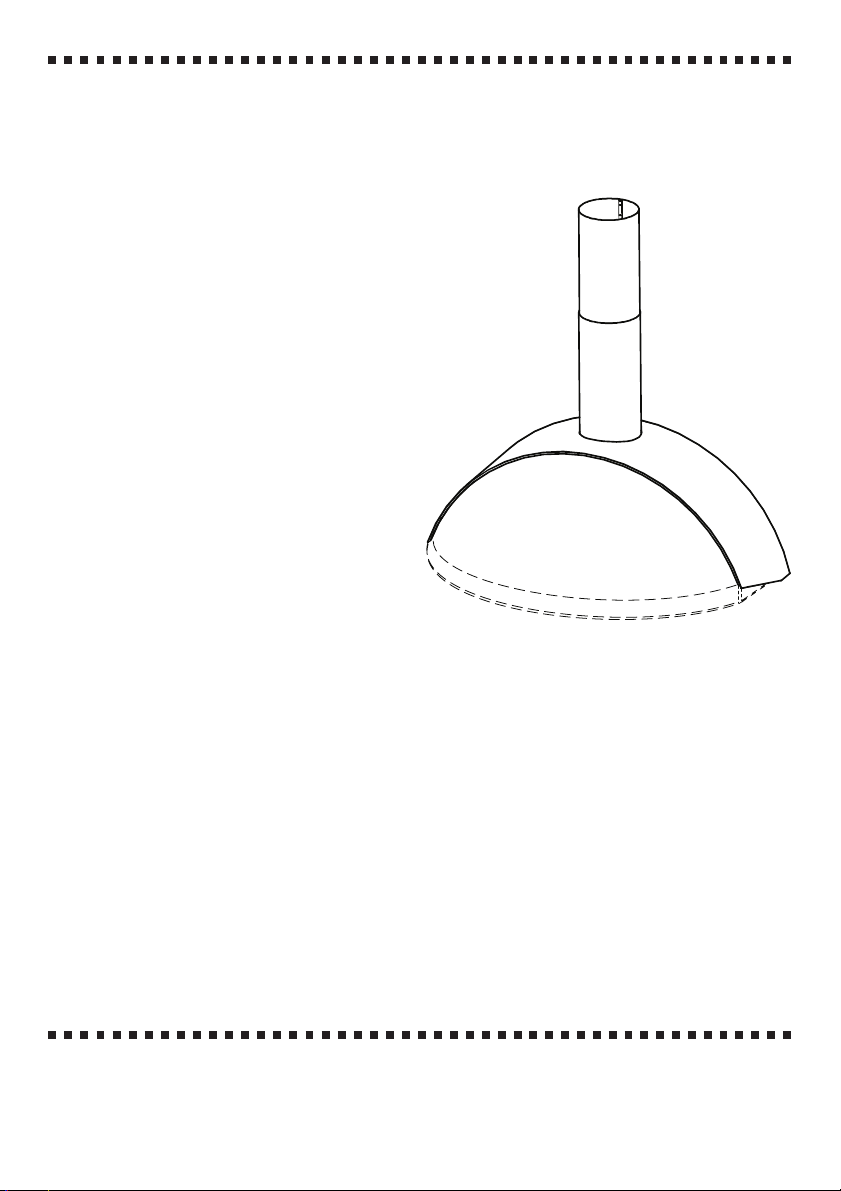
The cooker hood is made up of (fig. 1):
2.1 - 1 canopy C complete with light controls and ventilating unit
2.2 - 1 telescopic chimney stack made up of:
1 upper stack S
1 lower stack I
2.3 - 1 reduction flange 150-120 Ø A
2.4 - 1 stack fitting R
2.5 - 1 directional grill G
2.6 - 1 bag containing:
1 bracket I for fixing the hood unit, screws, rawl plugs and documents
2.7 - 1 backing B (optional)
3 - SAFETY WARNINGS
3.1- When used in the extraction mode the cooker hood ducting must not be connected to a
central heating flue, radiator or a water heater.
3.2- Before connection to the mains supply ensure that the mains voltage corresponds withthe
voltage on the rating plate inside the hood.
3.3- Connect the hood to the mains supply via a double pole switch which has 3 mm
clearance between the contacts. When using a plug to connect the hood to the power
supply, ensure that the plug used complies with national safety regulations and that it is
connected in an easily accessible position.
3.4- Ensure that the electric plant allows the hood to be correctly earthed.
3.5- When installed, the hood must be positioned at least 65 cm above a cooking appliance.
3.6- Never do flambé cooking under this cooker hood.
3.7- Never leave frying pans unattended during use as overheated fats and oils may catch fire.
3.8- Before carrying out any kind of maintenance or cleaning, disconnect the hood from the
mains supply.
3.9- If the room where the cooker hood is to be used contains other non-electric appliances
(such as gas appliances) ensure that there is an adequate supply of air to the room. When
the coooker hood is used in conjunction with other appliances supplied with energy other
than electricity, the negative pressure in the room must not exceed 0,04 mbar to prevent
fumes been drawn back into the room by the cooker hood.
9
Page 5

Part 1 - INSTALLATION INSTRUCTIONS
4 - INSTALLATION
For ease of installation, use the following guide:
4.1 - Mounting the support bracket.
4.2 - Mounting the hood unit.
4.3 - Electrical connection and functional check.
4.4 - Exhaust and filter connection.
4.5 - Mounting the telescopic chimney stack.
4.1 - Mounting the support bracket. Backing.
Refer to (figs. 2a-b):
1 - On the wall draw a vertical line to the ceiling, in the centre of the area where the hood is to be
mounted. This enables vertical alignment of the various parts.
2 - Position the bracket I
a) Place the bracket I on the wall, aligning its centre (notches) on the vertical line at a distance
between the axis of its holes and the cooking surface:
1 - with backing: d = 300 + H mm, where H = height in mm of the visible part of the
backing. Due to the various types of backings available, this measurement must be taken
directly on the backing provided.
2 - without backing: d = at least 950 mm.
N.B. - Check that the bracket I is in a horizontal position. Minor adjustments can be made
using the hood regulating screws (see below).
b) Mark the centres of the two eyelet holes of the bracket on the wall.
3 - Using an 8 Ø mm bit, drill the marked centres, then fix firmly the bracket I using the 8 Ø
mm rawl plugs and screws provided.
4 - Backing (optional)
In this manner the distance of the cooker hood from the cooking surface is determined by the
height of the backing B and by the height of the bases. The backing is to be mounted before
mounting the hood unit and, if you wish to fix both upper and lower parts to the wall, it must
be mounted at the exact height before mounting the bases or the relative upper surface. Since
this operation is complex, it must be performed only by the kitchen installer or by competent
persons who know all the final measurements of the kitchen units. For upper fixing only,
proceed as follows:
a) Place the backing on the base surface as in fig. 2a. Set it against the wall and centre it with
respect to the base.
b) On the wall, mark the centres of the two holes of the upper flaps.
c) Using an 8 Ø mm bit, drill the holes in the wall and fix the backing using the 8 Ø mm rawl
plugs and screws provided.
d) If it is necessary to block the lower part, this must be done by the installer.
4.2 - Mounting the hood unit (fig. 3)
1 - Turn the two screws V (placed where the hood will be hooked) about halfway in.
2 - Hook the back part of the hood to the support bracket I fixed to the wall.
3 - Turn the screws V for vertical adjustment of the hood and level it horizontally.
4 - Insert and tighten the central fixing screw V1 (supplied) for final blocking.
10
Page 6

Part 1 - INSTALLATION INSTRUCTIONS
4.3 - Electrical connection and functional check
1 - Precautions 3.2, 3.3 and 3.4 of paragraph 3 on safety must be scrupulously adhered to.
2 - Make the electrical connection, check for proper functioning of the light, motor and change
of speed.
4.4 - Exhaust or filter connection
1 - Exhaust connection
a) The hood must be connected to external piping by means of a rigid or flexible 120 or 150
Ø pipe, as chosen by the installer. To install a 120 Ø pipe, the reduction flange A must be
placed at the hood outlet (fig. 4).
b) Connect the air outlet to the external pipe using the rigid or flexible pipe, using tightening
bands. Suitable material for this operation must be supplied by the installer.
c) Remove active carbon filters, if applicable (see paragraph 3.3.2, part 2).
2 - Filter connection
a) Filtered air is returned to the room through the directional grill G, to be mounted above
the shelf (fig. 5).
b) Add active carbon filters, if applicable, to the inside of the hood unit (see paragraph 3.3.2,
part 2).
4.5 - Mounting the telescopic chimney stack
1 - Fixing the telescopic chimney stack
a) The upper stack S must be fixed to the ceiling or to the shelf that delimits the upper part of
the kitchen units, as follows:
a) The chimney stack fitting R must be separated from the inside ring F by cutting the four
joining tabs (fig. 6). Part D may be used if an intermediary shelf is installed.
c) Position ring F on the ceiling or upper shelf in line with the hood outlet (fig. 7) and fix it
with two screws, if on the shelf, or two screws and two rawl plugs (provided) if to the ceiling.
d) Insert the upper chimney stack inside the lower chimney stack, along with the 120 Ø mm
connection pipe. Connect the connection pipe to flange A, then press the lower chimney stack
into the hood unit. During this assembly operation, take care to keep the series of fixing holes
in view (fig. 8). Push the upper chimney stack until it is inserted in the ring F. Fix the upper
chimney stack with the lower chimney stack by inserting in the appropriate hole one of the
screws supplied with the accessories (fig. 9). Turn the telescopic chimney stack until the series
of holes is facing the wall (fig. 10).
2 - Installation of an intermediary shelf.
a) Make a hole in the shelf so that the pipe can be inserted (fig. 11).
b) Part D, removed previously from fitting R, must be inserted in the telescopic chimney stack
before fixing to the hood, bearing in mind that it must be fixed to the lower part of the shelf.
c) Insert the shelf in the chimney stack and fix part D with the three screws provided (fig. 12).
11
Page 7

Part 2 - OPERATION AND MAINTENANCE INSTRUCTIONS
1 - SAFETY WARNINGS
It is most important that all the warnings shown in paragr. 3 of the Installation
instructions are strictly observed. Moreover pay special attention to the following
warnings during the use and maintenance of the cooker hood.
1.1 -The grease filters and the charcoal filter should be cleaned or replaced as recommended
by the manufacturer or more frequently if the hood is used consistently (over 4 hours per
day).
1.2 -When using a gas hob in conjunction with the cooker hood, never leave the burners
uncovered while the hood is in use; when removing the pans either turn the hob off or
keep the flame to a minimum if it is only for a few minutes and under supervision.
1.3 -Always ensure that the flame does not overflow from under the pans; this will save energy
and will avoid a dangerous concentration of heat.
1.4 - Do not use the appliance in any incorrect way: this hood has been designed only to
reduce the smells of cooking in the kitchen.
2 - USE
The layout of the control is as follows (fig. 13):
BUTTON L =Turns the lighting system on and off;
BUTTON V1 =Turns the on and off at low speed. This is ideal to obtain a particularly silent
but continuous flow of air when the level of cooking fumes is low;
BUTTON V2 =Medium speed, suitable for most normal operating conditions. This gives an
excellent ratio between treated air flow and noise level;
BUTTON V3 =High speed, suitable to deal with heavy cooking fumes, even for long periods
of time.
3 - MAINTENANCE
Continued maintenance guarantees proper functioning and best performance throughout
time. Special attention must be given to the grease filters and, for filtering hoods, to the active
carbon filters.
3.1 - Metal grease filter
1 - Cleaning
Wash this filter with a normal household detergent at least every 2 months. Its compact size
allows it to be washed even in a dishwasher.
2 - Removing the filters
a) Remove the vent grill by pressing the metal knobs toward the centre (fig. 14).
b) Remove the metal wire filter holder Q, remove the grease filter that is to be washed (fig.15).
c) Replace the washed and well-dried filter, reversing the removal sequence.
ATTENTION - Maintenance times must be respected as indicated in order to avoid fires
from grease-saturated filters.
3.3 - Active carbon filter
1 - Functioning
Active carbon filters are able to absorb odours until they are saturated. They are not washable
and cannot be regenerated, therefore they must be replaced every 4 months, or more often if
they are used intensely.
12
Page 8

Part 2 - OPERATION AND MAINTENANCE INSTRUCTIONS
2 - Replacement
Remove the exhaust grill, remove the active carbon filters at the ends of the diffuser by
turning them in the direction of the A arrows. Replace with new filters, turning them in the
direction of the B arrows (fig. 16), replace the exhaust grill.
3.4 - Illumination
Illumination can be with a 15 W neon tube or 2 40 W bulbs. For replacement, proceed as
follows (fig. 17):
a) Remove the metal terminals T. The glass will stay hooked to tabs Z.
b) Slide the glass to one side until the opposite end is free (arrow 1), then pull gently down
(arrow 2), then slide in the opposite direction (arrow 3) until the glass is freed. Replace the
bulb or neon tube and replace the glass, reversing the removal sequence.
3.5 - Cleaning
For normal hood cleaning:
- Do not use wet cloths or sponges, or jets of water.
- Do not use solvents or alcohol, which could damage painted surfaces.
- Do not use abrasive substances, especially on stainless steel surfaces.
It is advisable to use a damp cloth and a mild liquid detergent.
13
Page 9

1
2
31
Page 10

3
4
32
56
Page 11

7
8
9
10
11 12
33
Page 12

V1
V2
V3
L
13
14
15
34
16 17
Page 13

35
Page 14

Quest’apparecchio é conforme alla norma europea sulla bassa tensione C.E.E. 73/23 relativa
alla sicurezza elettrica e alle norme europee: C.E.E. 89/336 relativa alla compatibilità elettromagnetica e C.E.E. 93/68 relativa alla marcatura CE.
This appliance complies with European regulations on low voltages, EEC Directive 73/23 on
electrical safety, and with the following European regulations: EEC Directive 89/336 on
electromagnetic compatibility and EEC Directive 93/68 on EC marking.
Cet équipement est conforme à la norme européenne sur la basse tension C.E.E. 73/23
relative à la sécurité électrique et aux normes européennes: C.E.E. 89/336 relative à la
compatibilité électromagnétique et C.E.E. 93/68 relative au marquage CE.
Dieses Gerät entspricht den europäischen Niederspannungsrichtlinien 73/23/EWG zur
elektrischen Sicherheit, den europäischen Richtlinien 89/336/EWG zur elektromagnetischen
Verträglichkeit und den Richtlinien 93/68/EWG zur CE-Kennzeichnung
Dit apparaat voldoet aan de Europese Laagspanningsrichtlijn 72/23/EEG inzake de elektrische
veiligheid en aan de Europese normen 89/336/EEG inzake de elektromagnetische
compatibiliteit en 93/68/EEG inzake de CE-markering.
Este aparato respeta la norma europea de baja tensión C.E.E. 73/23 que hace referencia a la
seguridad eléctrica y a las normas europeas: C.E.E. 89/336 relativa a la compatibilidad
electromagnética y C.E.E. 93/68 relativa a la marca CE.
Este aparelho está conforme a norma européia sobre baixa tensão C.E.E. 73/23 referente à
segurança elétrica e às normas européias, C.E.E. 89/336 referente à compatibilidade
eletromagnética e C.E.E. 93/68 inerente à marcação CE
4329555 01 - 001206
 Loading...