

Page 1
Libretto Istruzioni
Instructions Booklet
Mode d’emploi
Bedienungsanleitung
Gebruiksaanwijzing
Duetto
Page 2

○○○○○○○○○○○○○○○○○○○○○○○○○○○○○○○○○○○○○○○○○○○○○○○
2
○○○○○○○○○○○○○○○○○○○○○○○○○○○○○○○○○○○○○○○
Page 3

○○○○○○○○○○○○○○○○○○○○○○○○○○○○○○○○○○○○○○○○○○○○○○○
IT
INSTALLAZIONE .......................................................................................... 6
Avvertenze per la sicurezza ................................................................................... 6
Componenti ......................................................................................................... 6
Istruzioni per l’installazione .................................................................................... 7
Montaggio della staffe di supporto e Fondale ............................................................7
Montaggio del corpo cappa ................................................................................... 8
Connessione elettrica e controllo funzionale .............................................................. 8
Connessione aspirante o filtrante ............................................................................ 9
Montaggio del camino telescopico ........................................................................ 10
USO ......................................................................................................... 11
Avvertenze per la sicurezza ................................................................................. 11
Istruzioni per l’Uso ............................................................................................. 11
MANUTENZIONE ....................................................................................... 12
Filtri antigrasso metallici ..................................................................................... 12
Filtro al carbone attivo ....................................................................................... 13
Illuminazione ...................................................................................................... 14
Pulizia .............................................................................................................. 14
GB
INSTALLATION .......................................................................................... 15
SAFETY WARNINGS ........................................................................................... 15
COMPONENTS .................................................................................................. 15
Installation instructions ...................................................................................... 16
Fitting the wall brackets and Splashback ................................................................16
Fixing the canopy................................................................................................ 17
Electrical connection and working test ...................................................................17
Ducting or Recirculation fitting ............................................................................. 17
Fitting the telescopic chimney .............................................................................. 19
OPERATION .............................................................................................. 20
Safety warnings ................................................................................................. 20
Instruction for Use ............................................................................................. 20
MAINTENANCE ......................................................................................... 21
Metal grease filters ........................................................................................... 21
Active carbon filter............................................................................................. 22
Lighting ............................................................................................................ 23
Cleaning ........................................................................................................... 23
○○○○○○○○○○○○○○○○○○○○○○○○○○○○○○○○○○○○○○○
3
Page 4

○○○○○○○○○○○○○○○○○○○○○○○○○○○○○○○○○○○○○○○○○○○○○○○
FR
INSTALLATION .......................................................................................... 24
CONSEILS CONCERNANT LA SECURITE ................................................................ 24
COMPOSANTS .................................................................................................. 24
Instructions pour l’installation .............................................................................. 25
Montage des étriers de support et sole ................................................................. 25
Montage du corps hotte ...................................................................................... 26
Raccordement électrique et contrôle fonctionnel. .................................................... 26
Connexion aspirante ou filtrante ........................................................................... 27
Montage de la cheminée télescopique ................................................................... 28
UTILISATION ............................................................................................. 29
CONSEILS CONCERNANT LA SECURITE ................................................................ 29
Instruction pour l’Utilisation ................................................................................ 29
ENTRETIEN .............................................................................................. 30
Filtres à graisses métalliques .............................................................................. 30
Filtre au charbon actif ........................................................................................ 31
Eclairage .......................................................................................................... 32
Nettoyage ......................................................................................................... 32
DE
MONTAGE ................................................................................................ 33
SICHERHEITSHINWEISE...................................................................................... 33
Bestandteile ...................................................................................................... 34
Installationsanweisungen .................................................................................... 34
Montage der Haltebügel und der Rückwand ........................................................... 34
Montage des Haubenkörpers ...............................................................................36
Elektrischer Anschluß und Funktionskontrolle .......................................................... 36
Anschluss für Abluft- oder Umluftbetrieb ................................................................ 36
Montage des Teleskopkamins ............................................................................... 38
GEBRAUCH ............................................................................................... 39
SICHERHEITSHINWEISE...................................................................................... 39
AREITSWEISE DER DUNSTHAUBE ....................................................................... 39
WARTUNG UND PFLEGE ............................................................................ 40
Metall-Fettfilter ................................................................................................. 40
Aktivkohlefilter ................................................................................................... 41
Beleuchtung ...................................................................................................... 42
Pflege ............................................................................................................... 42
4
○○○○○○○○○○○○○○○○○○○○○○○○○○○○○○○○○○○○○○○
Page 5

○○○○○○○○○○○○○○○○○○○○○○○○○○○○○○○○○○○○○○○○○○○○○○○
NL
MONTAGE ................................................................................................ 43
WAARSCHUWINGEN VOOR DE VEILIGHEID........................................................... 43
Onderdelen ....................................................................................................... 43
Aanwijzingen voor de installatie ............................................................................ 44
Montage van de steunbeugel en het spatscherm .................................................... 44
Montage van de wasemkap .................................................................................45
Aansluiting op het elektriciteitsnet en controle van de werking ................................... 45
Aansluiting in de afzuigende of filterende versie ....................................................... 46
Montage van de telescopische schouw ..................................................................47
GEBRUIK .................................................................................................. 48
VEILIGHEIDSMAATREGELEN................................................................................ 48
HANDLEIDING ................................................................................................... 48
ONDERHOUD ............................................................................................ 49
Metalen antivet-filter .......................................................................................... 49
Koolstoffilter ..................................................................................................... 50
Verlichting ........................................................................................................ 51
Reiniging ........................................................................................................... 51
○○○○○○○○○○○○○○○○○○○○○○○○○○○○○○○○○○○○○○○
5
Page 6

○○○○○○○○○○○○○○○○○○○○○○○○○○○○○○○○○○○○○○○○○○○○○○○
2
A
R
P1
D
P
G
B
V
S
I
C
INSTALLATION
○○○○○○○○○○○○○○○○○○○○○○○○○○○○○○○○○○○○○○○○○○○○○○○
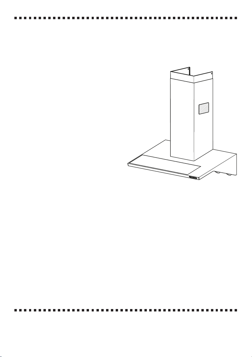
This canopy hood is designed to be fixed to any rigid vertical surface, over a gas or
electric hotplate and can be used either in the extraction mode (ducted to the outside) or
in the recirculation mode (internal recycling).
SAFETY WARNINGS
• Before commencing the installation, consideration should be given to the difficulties
to be found during installation and to the bulky weight of the hood. The installation
work must be undertaken by a qualified and competent person in conformity to the
rules concerning the evacuation of contaminated air. The manufacturer disclaims all
liability for any damage or injury caused as a result of not following the instructions
for installation contained in the following text.
• When used in the extraction mode the cooker hood ducting must not be connected to
a flue which is used for exhausting fumes from appliances supplied with energy other
than electric such as a central heating flue or water heating flue.
• When istalled, the hood must be positioned at least 65 cm above a cooking appliance.
• Never do flambé cooking under this cooker hood.
• Never leave frying pans unattended during use as overheated fats and oils may catch
fire.
• If the room where the cooker hood is to be used contains a fuel burning appliance
such as a central heating boiler then this must be of the room sealed or balanced flue
type. If other types of flue or appliance are fitted en-sure that there is an adequate
supply of air into the room. When the cooker hood is used in conjunction with other
appliances supplied with energy other than electric, the negative pressure in the room
must not exceed 0,04 mbar to prevent fumes being drawn back into the room by the
cooker hood.
COMPONENTS
The hood comprises the following (fig.1 ):
• No.1 canopy C complete with controls,
lighting and ventilator unit
• No.1 telescopic chimney, comprising:
No.1 upper chimney element S
No.1 lower chimney element I
• No.2 directional grills G
• No.1 reduction flange Ø 150-120 A
• No.1 valve V (optional )
• No.1 recirculation spigot R
• No.1 deflector D
• No.2 additional side recirculation spigots
P1
• No.1 additional recirculation spigot P
• No.1 bag containing:
No.2 brackets 2 to fix the chimney,
screws, rawl plugs and documents.
• No.1 splashback B (optional)
2
V
A
P1
R
D
P
Fig. 1
C
B
S
G
I
○○○○○○○○○○○○○○○○○○○○○○○○○○○○○○○○○○○○○○○
15GB
Page 7

○○○○○○○○○○○○○○○○○○○○○○○○○○○○○○○○○○○○○○○○○○○○○○○
232
195
11
2
20
X
H min 650
d = 1045 min
Installation instructions
For easy installation, proceed as follows:
• Fix the wall brackets and Splashback
• Fix the canopy
• Connect the hood to the mains power supply and make sure that it works properly
• Set the hood for ducting or recirculation
• Fix the telescopic chimney
Fitting the wall brackets and Splashback
Please refer to (fig.2a-b):
• Draw a vertical line on the
wall, from the centre of the
cooking appliance up to the
ceiling, using a marking pen.
This is to ensure the correct
vertical alignment of the
various parts.
• Fixing the wall brackets
item
2:
a) Place one of the brackets
2
against the wall
approximately 1 or 2 mm
from the ceiling or from the
top limit, aligning its centre
(slot) with the vertical line.
b) Mark the centres of two
keyholes in the bracket on
the wall.
c) Rest the other bracket 2
a b
against the wall, aligning it
with the vertical line, at a
distance X measured as
shown in fig. 2 equal to the height of the upper chimney element S supplied with the
hood. The position X may vary, according to the various sizes of upper chimney element
available.
d) Mark the centres of the keyholes in the bracket on the wall.
• Drilling fixing holes item 1:
a) Mark a point on the vertical line at a distance from the cooking appliances of:
d =1045 min (distance without splashback).
d =height of splashback + 395 mm (distance with splashback).The distance H is the
minimum height in mm from the cooking appliances to the bottom edge of the front panel
of the hood.
b) At the point marked, draw a horizontal line parallel to the cooking appliances.
c) Drill two holes in the wall
1 using an 8 mm drill bit (fig.2a ), and insert the rawl plugs and
screws into the holes 1 (4.2 x 44.4 screws). Fix the screws, leaving a space of 5-6 mm
required to hook up the canopy. Small adjustments can be made using the hood adjustment
Fig. 2
16
○○○○○○○○○○○○○○○○○○○○○○○○○○○○○○○○○○○○○○○
GB
Page 8

○○○○○○○○○○○○○○○○○○○○○○○○○○○○○○○○○○○○○○○○○○○○○○○
1
1
1
A
screws (see Fitting the canopy). The hood should have a
maximum excursion of 20 mm.
• Splashback (optional)
When a splashback is to be fitted, the distance between the
hood and the cooking appliances will be determined by the
height of the splashback
back on the worktop. The splashback is to be installed before
installing the canopy. If the splashback is to be fixed to the
wall using both the top and bottom fixing holes, care must be
taken to ensure that the splashback is fitted at the correct height
before fixing the base units or at least the worktop covering
them. As this is a complex operation, it should only be
undertaken by the technician installing the kitchen units or by a
competent person who knows the final dimensions of the
units. If the splashback is to be fixed through the top fixing
holes only, proceed as follows:
a) Rest the splashback on the worktop and against the wall, as
illustrated in fig.2 .
b) Mark the centres of the two holes in the top surface.
c) Drill the wall using an 8 mm drill bit, and fix the splashback
using the rawl plugs and screws provided.
d) If necessary, the installer should secure the splashback to
the wall by tucking the bottom edge down behind the rear of
the worktop.
B and whether or not there is a raised
S1S1S1
Fig. 3
1
Fixing the canopy
Before starting to fix the canopy it will be necessary to adjust
the support brackets S1 by turning the adjustment screws in
a clockwise direction until their reach their limit (Fig.3):
a) Hook the canopy onto the two size 4.2 x 44.4 screws
described above (Fig.4 ).
b) Level the hood by turning the adjustment screws and then locking
them.
1 fitted as
Fig. 4
Electrical connection and working test
• Before connecting to the mains supply ensure that the mains
voltage corresponds with the voltage on the rating plate inside
the hood.
• Connect the cooker hood to the mains via a double pole switch
which has 3 mm clearance between the contacts.
• The appliance must be earthed.
• Once the electrical connection has been completed, check that
worktop illumination, motor and speed work properly.
Ducting or Recirculation fitting
• Ducting fitting
• The hood can be ducted to the outside using either rigid or flexible
ducting Ø 120 or 150 mm, the choice of which is left to the installer.
When 120 mm ducting is to be used it will be necessary to install
the reduction flange item A on the air outlet (fig.5).
A
Fig. 5
S1
1
1
○○○○○○○○○○○○○○○○○○○○○○○○○○○○○○○○○○○○○○○
17GB
Page 9

○○○○○○○○○○○○○○○○○○○○○○○○○○○○○○○○○○○○○○○○○○○○○○○
D
R
P1P1
P
R
P1P1
P
G
• When ducting the hood through the side air outlet from
the lower chimney element
deflector D into spigot R to close off the opening that is
not being used (fig.6).
• Cut the additional spigot P in correspondence with outlets
1 and 2 , which must be formed directly on the piece.
Connect the additional spigot P to the round fan outlet,
pushing it downwards, and fit spigot R to additional spigot
P in a similar manner (make sure that the two additional
side recirculation spigots P1 are fitted to spigot R). Make
sure that the height of the assembly R + P corresponds
to the height of the chimney outlet (fig. 7).
• If the hood is supplied with the activated charcoal filters
fitted, the filters should be removed (see paragraph on
Maintenance ).
• Recirculation fitting
• The filtered air is returned to the room through the two
plastic side grills G on the lower chimney element I .
• Connect the additional spigot
pushing it downwards, and fit spigot R to additional spigot
P in a similar manner (make sure that the two additional
side recirculation spigots P1 are fitted to
spigot R). Cut the additional spigot P in
correspondence with outlets 1 and 2 , which
must be formed directly on the piece. Make
sure that the height of the assembly R + P
corresponds to the height of the chimney
outlet.(fig.7).
• Fit the activated charcoal filters inside the
canopy (see paragraph on Maintenance ).
Do not fit the venting grilles until after the
chimney has been installed.
I it is necessary to insert
P to the round fan outlet,
R
P
P1P1
R
D
P
Fig. 6
P1P1
G
Fig. 7
18
○○○○○○○○○○○○○○○○○○○○○○○○○○○○○○○○○○○○○○○
GB
Page 10

○○○○○○○○○○○○○○○○○○○○○○○○○○○○○○○○○○○○○○○○○○○○○○○
G
A
1
8
_
7
1
4
_
0
3
2
S
I
2
C
Fitting the telescopic chimney
• To fit the upper section S first expand the two
side pieces slightly, hook them behind the
brackets 2 and close them together again until
they touch. Fix the upper section S to the
brackets 2 using four of the screws provided
in the bag of accessories (fig. 8).
• Fit the lower section I as above, between the
upper section S and the canopy C using two
of the screws provided in the bag of
accessories.
• Chimney with venting grilles: Snap the venting
grilles into position in the apertures located
on the chimney section, so that the symbol
is turned upwards and the symbol faces
forwards. Also, when the hood is used in
recirculation mode, ensure that the grilles are
properly secured to the inside of the
recirculation spigot
R (fig.9).
S
I
C
Fig. 8
A
1
8
_
7
1
4
_
0
3
2
2
G
Fig. 9
○○○○○○○○○○○○○○○○○○○○○○○○○○○○○○○○○○○○○○○
19GB
Page 11

○○○○○○○○○○○○○○○○○○○○○○○○○○○○○○○○○○○○○○○○○○○○○○○
OPERATION
○○○○○○○○○○○○○○○○○○○○○○○○○○○○○○○○○○○○○○○○○○○○○○○
Safety warnings
• Before carring out any kind of maintenance or cleaning, disconnect the hood from the mains
supply.
• The grease filters and the charcoal filter should be cleaned or replaced as recommended by
the manufacturer or more frequently if the hood is used consistently over 4 hours per day.
• When using a gas hob in connection with the cooker hood never leave the burners of the
hob uncovered while the hood is in use or when the pans have been removed. Switch off
the gas before removing the pan, or for just short periods and never leave the hob unattended.
• Always ensure that the flame is kept at the correct intensity to prevent the flame from
licking round from the bottom of the pan; this will save energy and will avoid a dangerous
concentration of heat.
• Always ensure that the appliance is used in accordance with the manufacturer’s
instructions for the removal of contaminated air and odours during cooking.
Instruction for Use
Control Panel (fig. 10)
The layout of the control panel is as follows:
Button T1 = Turns the lighting system on and off
Button T2 = Turns the motor on and off
Button T3 = Decreases the working speed
Button T4 = Increases the working speed
Button T5 = Intensive speed with timed stoppage. Suitable to deal with maximum vapour
emission, this turns off automatically ten minutes after starting operation.
It can be disabled by pressing the button T5.
T1 T2 T3 T4 T5
Fig. 10
20
○○○○○○○○○○○○○○○○○○○○○○○○○○○○○○○○○○○○○○○
GB
Page 12
○○○○○○○○○○○○○○○○○○○○○○○○○○○○○○○○○○○○○○○○○○○○○○○
MAINTENANCE
○○○○○○○○○○○○○○○○○○○○○○○○○○○○○○○○○○○○○○○○○○○○○○○
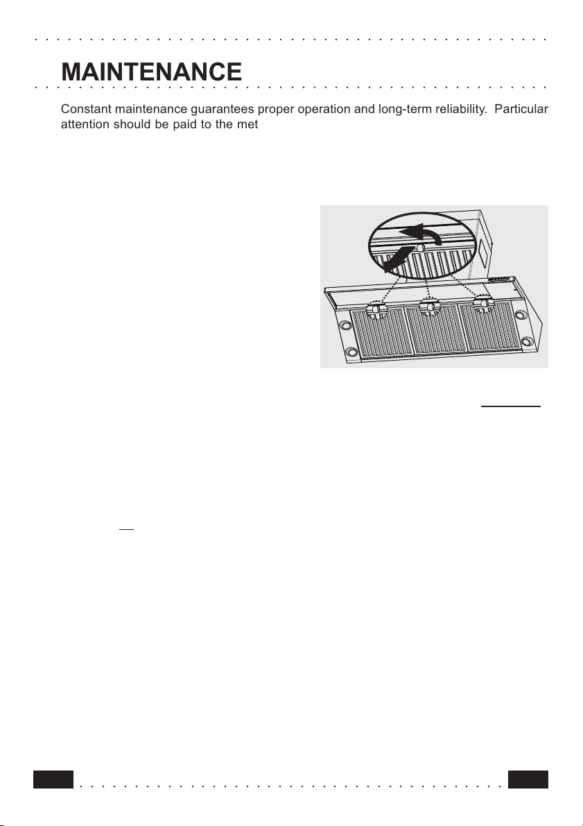
Constant maintenance guarantees proper operation and long-term reliability. Particular
attention should be paid to the metal grease filters and, for recirculation hoods only, to
the activated charcoal filters. The appliance is equipped with a system that indicates
automatically when it is time to carry out maintenance operations.
Metal grease filters
• Cleaning
These filters must be washed when LED
Filters starts, or at the most once every 2
months, using a normal household detergent;
their compact size also enables them to be
washed in a dishwasher.
• Removing the filters
Remove one filter at a time, pulling and
turning the handle in an anticlockwise
direction – see fig. 11. Replace by repeating
the same operations in reverse order, making
sure that the handle is turned to face the
outside.
• Enabling the alarm signal
The hood is already set up to trigger an alarm
indicating saturation of the metal grease
filters, so this function does not need to be
enabled.
• Resetting the alarm signal
To turn the alarm signal off, proceed as
follows:
- Turn off the lights and the suction motor;
- Press the T4 button for at least 3 seconds,
until the LEDs flash in confirmation. In any
case the saturated filters alarm will only come
into operation when the suction motor is
turned on.
WARNING: always comply with the
maintenance and replacement times
indicated, in order to avoid a possible risk
of fire when the filters are saturated with
grease.
Fig. 11
○○○○○○○○○○○○○○○○○○○○○○○○○○○○○○○○○○○○○○○
21GB
Page 13

○○○○○○○○○○○○○○○○○○○○○○○○○○○○○○○○○○○○○○○○○○○○○○○
Active carbon filter
• Operation
The activated charcoal filter is only fitted in
recirculation type hoods. It will retain odours until
it becomes saturated. It cannot be washed or
regenerated, and must be replaced when the
Filters LED starts, or at least once every 4 months
of use. This indicates that as well as replacing the
activated charcoal filter, it is also necessary to
perform maintenance operations on the metal
grease filters.
• Replacing
Remove the grease filters and take out the
activated charcoal filter from its housing, turning
the lugs provided (fig. 12). Insert the new activated
charcoal filter and replace the metal grease filters.
• Enabling the alarm signal
In recirculation type hoods the saturated filters
alarm must be enabled as indicated below:
- Turn off the lights and the suction motor;
- Press and hold the T4 button for at least 10
seconds, until the LEDs start to flash. Note the
number of flashes:
- 2 flashes of the LED Activated charcoal filter
saturation alarm ENABLED.
- 1 flash of the LED Activated charcoal filter
saturation alarm DISABLED;
• Resetting the alarm signal
To turn the alarm signal off, proceed as follows:
- Press the T4 button for at least 3 seconds, until
the LEDs flash in confirmation. In any case the
saturated filters alarm will only come into operation
when the suction motor is turned on.
WARNING: always comply with the
maintenance and replacement times indicated,
in order to avoid a possible risk of fire when
the filters are saturated with grease.
Fig. 12
22
○○○○○○○○○○○○○○○○○○○○○○○○○○○○○○○○○○○○○○○
GB
Page 14

○○○○○○○○○○○○○○○○○○○○○○○○○○○○○○○○○○○○○○○○○○○○○○○
Lighting
• Version with halogen spotlights:
90 cm model, four 20W halogen
spotlights.
• To replace (fig.13)
Remove the two screws fixing the
metal ring, extract the spotlight from
the lamp holder by pulling gently.
When replacing the spotlight, make
sure that the two pins are correctly
inserted in the housing on the lamp
holder.
Cleaning
When cleaning the hood:
- Never use a wet cloth or sponge, or
running water.
- Never use thinners or products
containing alcohol, as they might
damage the paintwork.
- Never use abrasive cleaning materials,
in particular when cleaning stainless
steel surfaces.
It is recommended to use a damp
cloth and mild liquid household
cleaner.
Fig. 13
○○○○○○○○○○○○○○○○○○○○○○○○○○○○○○○○○○○○○○○
23GB
 Loading...