

Page 1

SERVICE MANUAL
Model HF3434D
Page 2

CONTENTS
SERVICE ACCESS
FACE PLATE UNIT ............................................................................................................1
BACK COVER UNIT ..........................................................................................................2
FRONT COVER UNIT ....................................................................................................... 3
SIDE COVER UNIT ........................................................................................................... 4
MACHINE BASE ................................................................................................................ 5
MECHANICAL ADJUSTMENT
MACHINE SOCKET...........................................................................................................6
NEEDLE BAR HEIGHT......................................................................................................7
PRESSER BAR HEIGHT ................................................................................................... 8
FEED DOG HEIGHT..........................................................................................................9
TIMING OF THE NEEDLE AND THE FEED DOG ............................................................10
TIMING OF THE NEEDLE AND THE UPPER KNIFE ....................................................... 11
HEIGHT OF THE LOWER LOOPER .................................................................................12
CLEARANCE BETWEEN THE NEEDLES AND THE LOWER LOOPER
/NEEDLE GUARDS ...................................................................................................13-15
CLEARANCE BETWEEN THE NEEDLES
AND THE FIXED NEEDLE GUARD .........................................................................16
POSITION OF THE CHAINING FINGER .......................................................................... 17
POSITION OF THE UPPER LOOPER ..............................................................................18
TIMING OF THE NEEDLE AND THE LOWER LOOPER ..................................................19
TIMING OF THE UPPER AND LOWER LOOPERS ..........................................................20
CLEARANCE BETWEEN THE LOOPERS........................................................................21
CLEARANCE BETWEEN THE NEEDLE AND THE UPPER LOOPER .............................22
POSITION OF THE KNIVES ............................................................................................. 23
POSITION OF THE LOWER LOOPER THREAD GUIDE .................................................24
STITCH LENGTH .............................................................................................................. 25
THREAD TENSION DIALS ................................................................................................26
PLAY OF MAIN SHAFT ..................................................................................................... 27
BELT TENSION .................................................................................................................28
OILING ........................................................................................................................... 29
GAUGES FOR SERVICING .......................................................................................... 30
PARTS LIST .................................................................................................................. 31-50
Page 3
1
MODEL 3434D
FACE PLATE UNIT
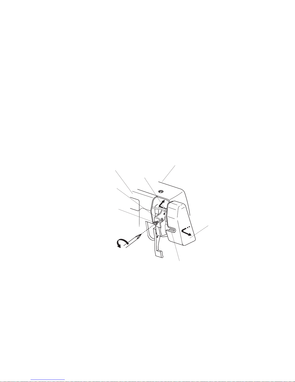
To remove:
1. Loosen the set screw A and remove the face plate unit.
To attach:
2. Fit the U-groove of the face plate between the setscrew A and set plate, put the rib of face
plate into the front cover unit and back cover unit and tighten the setscrew.
Setscrew A
Face plate unit
U-groove
Set plate
Back cover unit
Rib
Front cover unit
SERVICE ACCESS
Page 4
2
MODEL 3434D
BACK COVER UNIT
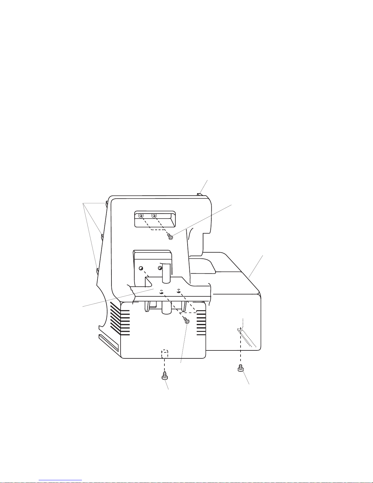
To remove:
1. Remove setscrews A and the spool stand.
2. Remove setscrews B,C and D.
3. Remove the back cover unit.
To attach:
4. Put the ribs of back cover into the front cover unit and tighten setscrews B, C and D.
5. Attach the spool stand with setscrew A.
Back cover unit
Setscrew B
Setscrew C
Setscrew A
Setscrew D
Rib
Rib
Spool stand
SERVICE ACCESS
Page 5
3
MODEL 3434D
FRONT COVER UNIT
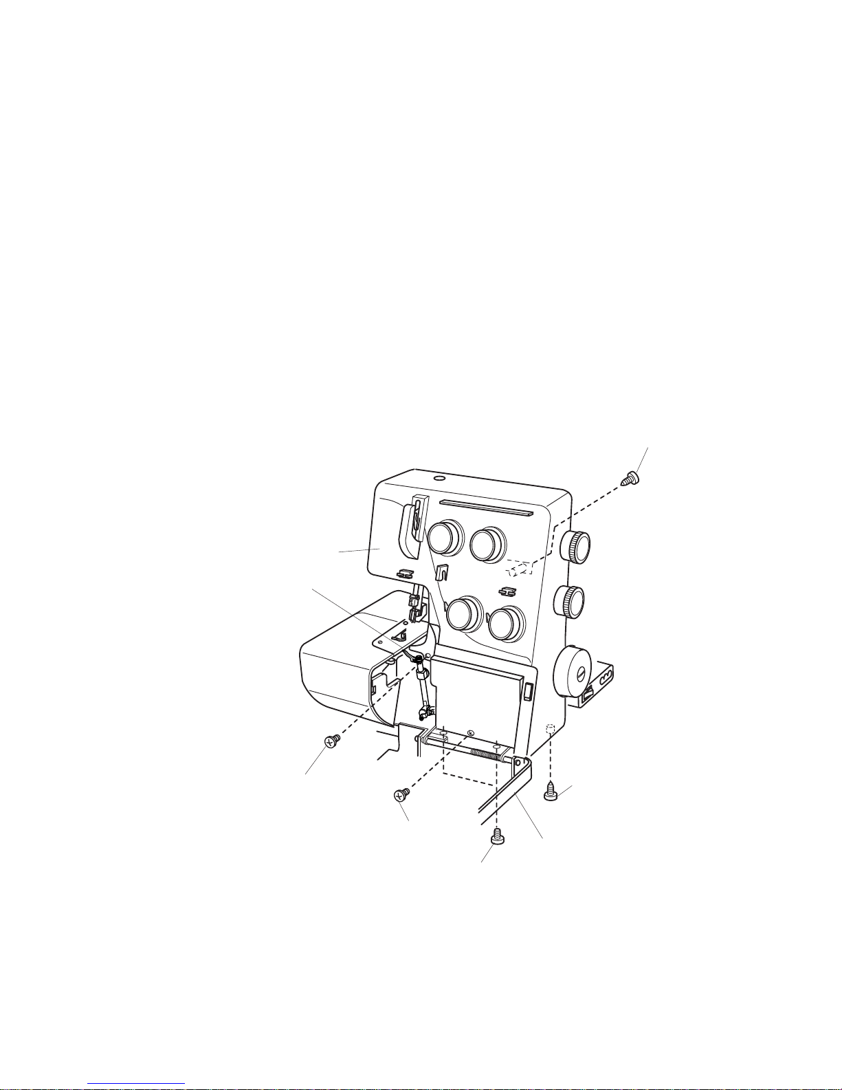
To remove:
1. Remove setscrews A and the looper cover unit.
2. Remove the face plate unit and the back cover unit.
3. Turn the hand wheel toward you with your hand, and set the upper looper at lowest position,
and remove setscrews B, C, D,E and the front cover unit.
To attach:
4. Attach the front cover unit with setscrews B, C, D and E.
5. Attach the looper cover unit with setscrew A.
6. Attach the back cover unit and face plate unit.
Setscrew C
Setscrew D
Upper looper should be set
at lowest position
Front cover unit
Looper cover unit
Setscrew A
Setscrew E
Setscrew B
SERVICE ACCESS
Page 6
4
MODEL 3434D
SIDE COVER UNIT
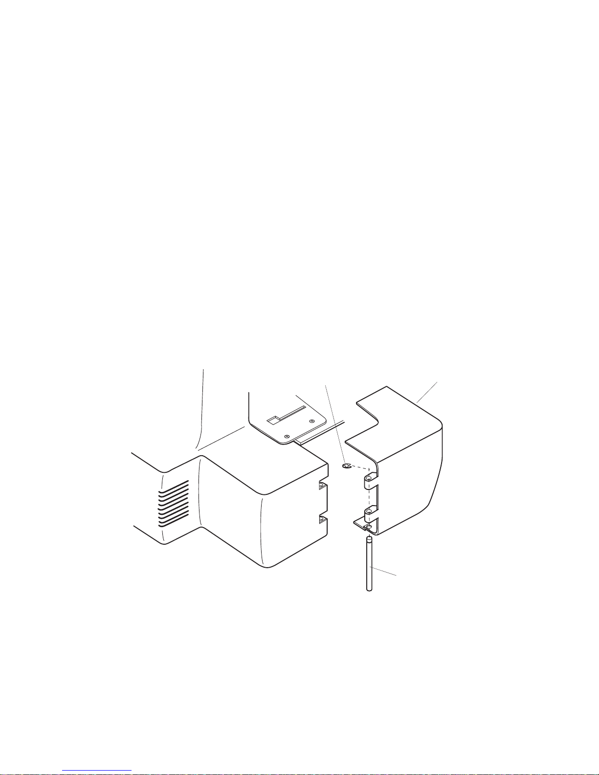
To remove:
1. Open the side cover unit. Remove the snap ring E-3 and pull out the shaft.
To attach:
2. Attach the side cover unit and insert the shaft and attach the snap ring.
Side cover unit
Snap ring E-3
Shaft
SERVICE ACCESS
Page 7
5
MODEL 3434D
MACHINE BASE
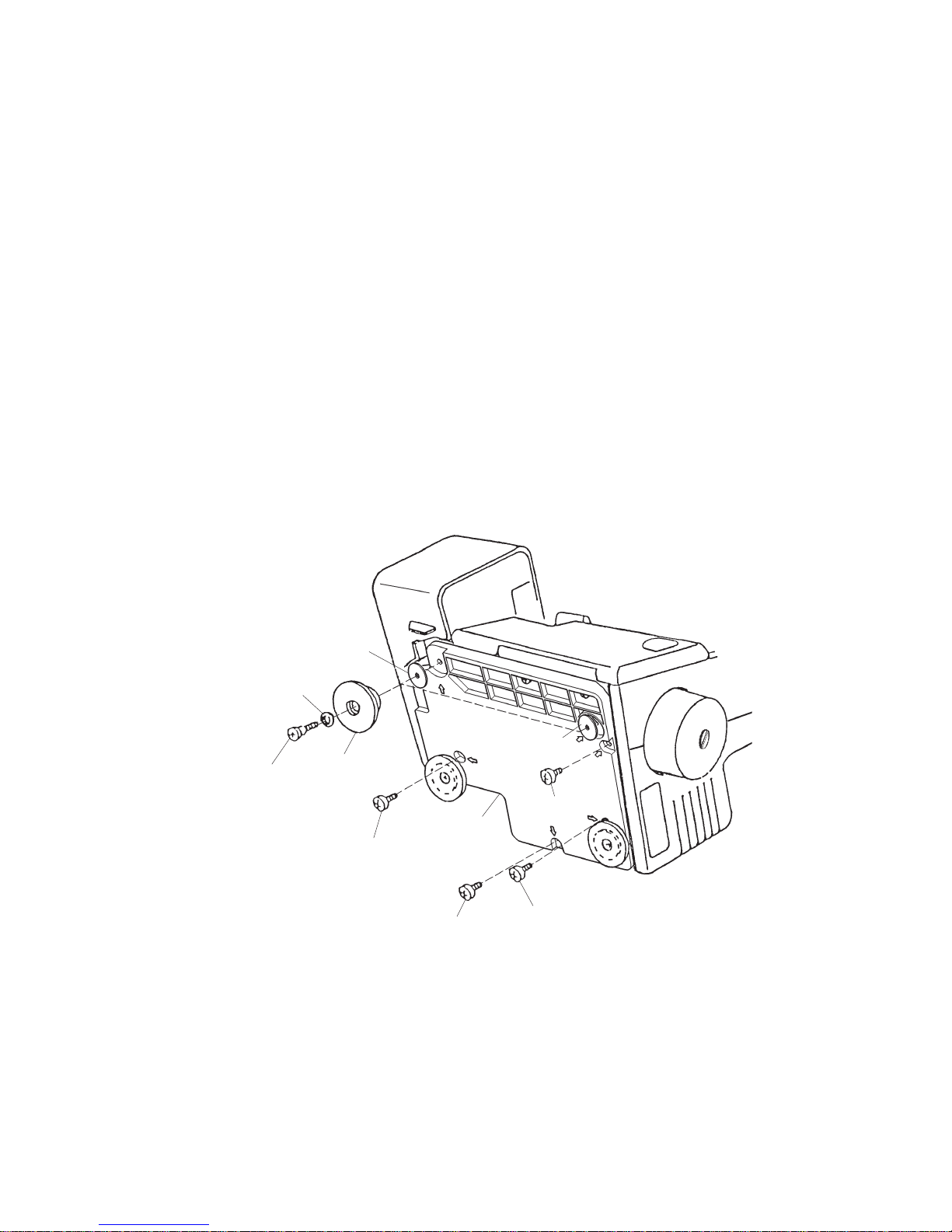
To remove:
1. Remove setscrews A, B, C, D and two hinge screws E, and remove two base cushions F
and washers.
2. Remove the machine base.
NOTE: Do not remove the remaining two base cushions.
To attach:
3. Attach the machine base unit, and tighten setscrews A, B, C and D.
4. Attach the two base cushions F, washers, and tighten hinge screws E.
Washer (thick)
Washer
Base
cushion F
Hinge screw E
Setscrew D
Setscrew C
Setscrew B
Machine base
Setscrew A
Washer (thin)
SERVICE ACCESS
Page 8

6
MODEL 3434D
MACHINE SOCKET
To remove:
1. Remove the back cover unit.
2. Remove the setscrews (A, B) and the machine socket unit from the motor fixing plate.
3. Remove the two setscrews C, and pull out the cord connectors.
To attach:
4. Insert the cord connectors as shown below.
5. Attach the machine socket, and tighten the two setscrews C.
6. Attach the machine socket unit on the motor fixing plate and tighten the setscrews (A, B).
7. Attach the back cover unit.
To motor
To lamp socket
Setscrews C
Machine socket
Lamp socket lead cord
Motor lead cord
Lamp socket lead cord
Setscrews B
Setscrews A
Motor fixing plate
MECHANICAL ADJUSTMENT
Page 9
7
MODEL 3434D
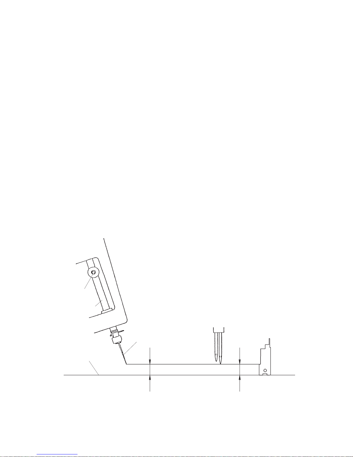
NEEDLE BAR HEIGHT
Correct Setting:
The distance between the tip of needle on the right and the surface of needle plate should be 11.6 to
12.2 mm when the needle bar is at the highest position.
To adjust:
1. Remove the looper cover unit, face plate unit, back cover unit and front cover unit.
2. Turn the handwheel toward you with your hand, and set the needle bar at the highest position.
3. Loosen the set screw A to adjust the height, and tighten set screw A after the adjustment is done.
4. Turn the handwheel toward you one cycle, and recheck the needle bar height.
5. Attach the front cover unit, looper cover unit, back cover unit and face plate unit.
Setscrew A
Needle bar
Surface of needle plate
Needle #14
11.6 to 12.2 mm
11.6 mm
O.L G05
MECHANICAL ADJUSTMENT
Page 10
8
MODEL 3434D
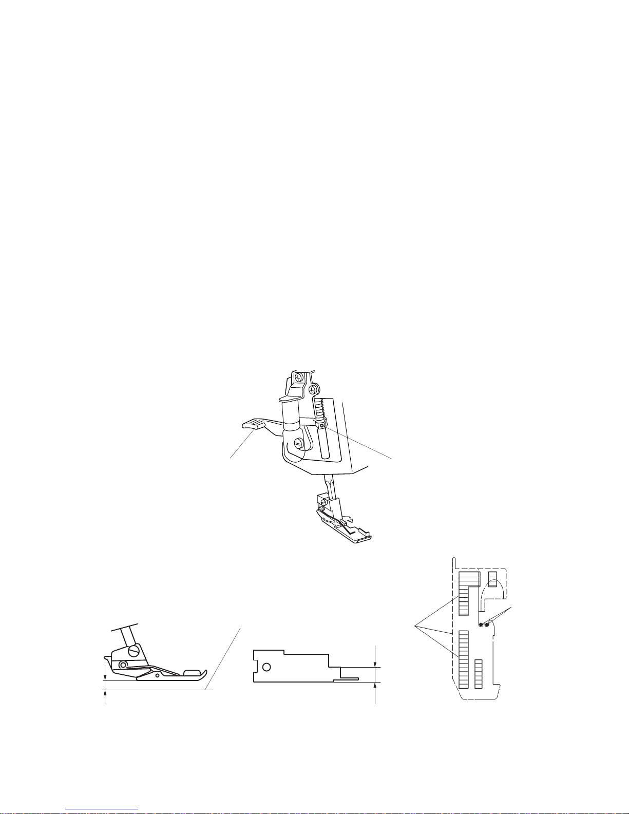
PRESSER BAR HEIGHT
Correct Setting:
The distance between the surface of needle plate and bottom of presser foot should be 4.7 to
5.3 mm when the presser bar lifter is raised.
To adjust:
1. Remove the looper cover unit, face plate unit, back cover unit and front cover unit.
2. Raise the presser bar lifter and loosen set screw A.
Then adjust the presser bar height (Use the service gauge O.L G05.). The presser foot
should be parallel with the slots of the needle plate.
3. Tighten the set screw A.
4. Attach the front cover unit, looper cover unit, back cover unit and face plate unit.
Top surface of needle plate
4.7 ~ 5.3 mm
5 mm
O. L G05
To be parallel
(Direction of presser foot)
Setscrew A
Presser bar lifter
Needle
MECHANICAL ADJUSTMENT
Page 11

9
MODEL 3434D
FEED DOG HEIGHT
Correct Setting:
When the presser foot is lowered and feed dogs are at their highest position, the distance between
the surface of needle plate and bottom of presser foot should be 0.75 to 0.95 mm.
To adjust:
1. Set the stitch length dial at “ 3 “ and the differential feed dial at “ 1.0 “ .
2. Remove the back cover unit.
3. Lower the presser foot and raise the feed dogs to their highest position by turning the handwheel.
4. Loosen the main & sub feed dog screws A, B (4 pcs.)
5. Push the main feed dog straight up and adjust the distance between the surface of needle
plate and bottom of presser foot to 0.85 mm (Use the service gauge O.L G05.), then tighten set
screws A (2 pcs.)
6. Turning the handwheel to get the top of the main feed dog is level with the surface of the needle
plate in the downward motion. Push the sub feed dog straight up until its top surface is to be
level with the top surface of needle plate. Then tighten the set screws B of the sub feed dog.
7. Turn the handwheel to check if the feed dog height.
8. Attach the back cover unit.
0.75 ~ 0.95 mm
Surface of needle plate
Push straight up
Setscrews B
Setscrews A
0.85 mm
O. L G05
MECHANICAL ADJUSTMENT
Page 12

10
MODEL 3434D
The top surface of feed dog
The top surface
of needle plate
2 ~ 4 mm
The end of feed movement
The clearance between the bushing
and feed cam should be about 1 mm
Set screw A
Bushing
Main feed cam
O. L G05
2 mm
Setscrew B
Direction D
Direction C
TIMING OF THE NEEDLE AND THE FEED DOG
Correct Setting:
With the presser foot lowered, the top of the feed dog should be level with the needle plate at the end
of feeding movement, when the tip of the right needle is 2-4 mm above the needle plate.
Before adjustment, check if the needle bar height and the feed dog height are correct.
To adjust:
1. Set the stitch length dial at “ 3 “ and differential feed dial at “ 1.0 “ .
2. Remove the back cover unit.
3. Raise the presser foot and turn the handwheel to bring the tip of right needle 3 mm above the
needle plate in its downward motion.
4. Lower the presser foot, and loose two set screws A for the main feed cam and two setscrews B for
the sub feed cam. Turn the main and sub feed cams to adjust the feed dog position then tighten the
setscrews.
–Turn the feed cams in the direction C if the feed dog is lower than the surface of the needle
plate.
–Turn the feed cams in the direction D if the feed dog is higher than the surface of the needle
plate.
5. Be sure that the clearance between the bushing and main feed cam is about 1 mm.
Attach the back cover unit.
MECHANICAL ADJUSTMENT
Page 13

11
MODEL 3434D
TIMING OF THE NEEDLE AND THE UPPER KNIFE
Correct Setting:
The upper knife timing is the same as that of the needle bar. In fact, when the needle bar is at highest
position, the upper knife should be also at its highest position.
To adjust:
1. Remove the back cover unit.
2. Loosen two setscrews A, and move the balance weight to left.
3. Loosen two setscrews B, and adjust the needle and upper knife timing.
– Turn the upper knife drive cam to the direction C when the upper knife timing is being delay.
– Turn the upper knife drive cam to the direction D when the upper knife timing is too soon.
4. Tighten the two setscrews B firmly. Move the balance weight to right.
Match the guide line on the balance weight with the one of the main shaft correctly.
Then tighten the two screws A.
5. Turn the handwheel toward you one cycle, and recheck the needle and the upper knife timing.
6. Attach the back cover unit.
When the needle bar goes up,
the upper knife goes up.
When the needle bar goes down,
the upper knife also goes down.
Direction C
Setscrew B
Setscrew A
Direction D
Guide line on main shaft
Upper knife drive cam
MECHANICAL ADJUSTMENT
Page 14

12
MODEL 3434D
HEIGHT OF THE LOWER LOOPER
Correct Setting:
The tip of the lower looper is 65.7 mm from the center of the lower shaft as shown below.
To adjust:
1. Set the upper knife in down position and loosen the setscrew A.
2. Turn the handwheel to get the lower looper in the left most position.
3. Set the lower looper height gauge No. 787-G02 on the lower looper shaft as shown.
NOTE: If there is not enough clearance between the lower looper unit and the lower looper thread
guide, remove the lower looper thread guide.
After the adjustment, attach the lower looper thread guide on the lower looper shaft as shown.
4. Move the lower looper up or down to match the tip of the looper with the guide line on the gauge.
5. Insert the gauge downwards into the lower looper shaft as shown.
6. Tighten setscrew A.
7. Remove the gauge and set the upper knife in up position.
Guide line of gauge
65.7 mm
(Servicing gauge
No.787-G01)
Lower looper thread guide
Lower looper shaft
Lower looper unit
Setscrew A
MECHANICAL ADJUSTMENT
Page 15

13
MODEL 3434D
CLEARANCE BETWEEN THE NEEDLES AND THE LOWER
LOOPER/NEEDLE GUARDS (1 of 3)
Correct Setting:
Both right and left needles should have an equal clearance from the front edge of the opening on the
needle plate.
The standard clearance between each needle and the lower looper is 0 mm to 0.5 mm.
The standard clearance between each needle and the rear needle guard is 0 mm to 0.2 mm.
Both needles slightly touch the front needle guard in a normal condition.
1. Clearance between needles and the opening of the needle plate
To adjust:
1. Remove the looper cover unit, face plate unit, back cover unit front cover unit and presser foot.
Replace the #14 needles with #11 needles.
2. Attach the needle gauge #787-G02 as shown to prevent change of needle bar height during the
adjustment.
Loosen the set screw C. Turn the needle bar in the direction D or E to get an equal clearance
between needles and the edge of the opening of the needle plate while pushing up the needle bar
to prevent a change of needle bar height.
Retighten the set screw C and remove the needle gauge.
Needle clamp
Setscrew C
Needle bar lower bushing
No clearance
Needle gauge
(787-G02)
Lower looper
Needle
(D)
(E)
Needle (R)
Equal clearance
Needle plate
Needle (L)
MECHANICAL ADJUSTMENT
Page 16

14
MODEL 3434D
CLEARANCE BETWEEN THE NEEDLES AND THE LOWER
LOOPER/NEEDLE GUARDS (2 of 3)
Rear needle guard
Lower looper
Front needle
guard
Hexagonal bolt (B)
Lower looper base
Needle #11
0 to 0.05 mm
Lower looper
Front needle
guard
Hexagonal socket
scerws (A)
Set screws (F)
Rear needle guard
2. Clearance between needles and the lower looper
1. Remove the left needle only.
2. Turn the handweel towards you to bring the tip of the lower looper from the left hand to the rear side
of the right needle.
3. Loosen the hexagonal socket screws A on the front needle guard and move it away from the
needle.
4. Next, loosen the hexagonal bolt B, and slide the lower looper base back or forth along the lower
looper shaft to get the clearance between the right needle and the lower looper.
The clearance should be 0 mm to 0.05 mm.
Retighten the hexagonal bolt B.
MECHANICAL ADJUSTMENT
Page 17

15
MODEL 3434D
CLEARANCE BETWEEN THE NEEDLES AND THE LOWER
LOOPER/NEEDLE GUARDS (3 of 3)
3. Clearance between needles and the rear needle guard
1. Change the right needle from #11 to #14.
2. Push the front needle guard against the needle to get the clearance between the needle and
the lower looper. The clearance should be 0 mm to 0.05 mm.
3. Attach #14 needle on the left and turn the handwheel towards you to check the clearance between
the left needle and looper. Tighten the hexagonal socket screws A.
Make sure the front needle guard is touching the needle slightly and the rear needle guard is not
touching the needle.
4. Check the timing between the needle and the lower looper.
5. Recheck the needle bar height and the clearance between the needle and the lower looper.
Needle #14
0 to 0.05 mm
Lower looper
Rear needle guard
Front needle guard
0 to 0.2 mm
(Rear needle guard is not touching the needle.)
Front needle guard
Rear needle guard
Hexagonal
socket
acrews (A)
MECHANICAL ADJUSTMENT
Page 18

16
MODEL 3434D
Fixed needle guard details
CLEARANCE BETWEEN THE NEEDLES AND THE FIXED
NEEDLE GUARD
Correct Setting:
The clearance between needle and the fixed needle guard should be 0.1 to 0.4 mm.
To adjust:
1. Remove the presser foot and the needle plate and lower the needle to its lowest position.
2. Loosen the setscrew A and adjust the position of the fixed needle guard.
3. Tighten the setscrew A.
4. Attach the needle plate and the presser foot.
Needle plate setting knob
Chaining finger
Fixed needle guard
No gap
The clearance between the needle
and fixed needle guard
Fixed needle guard
Needle #14
0.1 ~ 0.4mm
Setscrew A
Needle plate setting knob should be at “S”.
MECHANICAL ADJUSTMENT
Page 19

17
MODEL 3434D
POSITION OF THE CHAINING FINGER
Correct Setting:
There should be no gap between the chaining finger and the side of needle plate, and tip of chaining
finger should be the same level with the tip of the needle on the needle plate when the needle plate
setting knob is set at “S”.
To adjust:
1. Remove the presser foot.
2. Set the needle plate setting knob at “S”.
3. Loosen two setscrews A, and move chaining finger unit to the correct position.
4. Tighten two setscrews A.
5. Shift the needle plate setting knob from “S” to “R” and vice versa, then check the position of
chaining finger.
6. Attach the presser foot.
To be touched
Needle plate setting knob
Guide line S
Guide line R
Chaining finger unit
Setscrew A
Should be same level
MECHANICAL ADJUSTMENT
Page 20

18
MODEL 3434D
POSITION OF THE UPPER LOOPER
Correct Setting:
The clearance between the bottom of the upper looper and the upper looper shaft guide should be 1.6
to 1.8 mm when the upper looper is at its lowest position.
The distance between the center of needle on the right and the center of looper eye should be 4.8 to
5.2 mm when the upper looper is at its leftmost position.
To adjust:
1. Remove the machine base. Turn the handwheel to bring the upper looper to its lowest position.
2. Loosen the hexagonal socket screws A, and move the upper looper shaft up or down to adjust the
clearance between upper looper shaft guide and bottom of upper looper. The distance should be
1.6 to 1.8 mm as shown in Fig. 1.
3. Tighten the hexagonal socket screws A.
4. Turn the handwheel to bring the upper looper to the leftmost position.
5. Loosen the hexagonal socket screw B, and slide the upper looper to adjust the distance between
the center of needle and center of upper looper eye as shown in Fig. 2 and Fig. 3.
6. Tighten the hexagonal socket screw B.
7. Check the upper and lower loopers timing and clearance between upper and lower loopers.
1.7 mm
O.L G05
Needle on the right
5 mm
4.8 to 5.2 mm
(Fig. 2)
Upper looper
Hexagonal socket screw B
(Fig. 3)(Fig. 1)
Upper looper shaft
Upper looper shaft guide
Upper looper
1.6 to 1.8 mm
Hexagonal socket screws A
MECHANICAL ADJUSTMENT
Page 21

19
MODEL 3434D
TIMING OF THE NEEDLE AND THE LOWER LOOPER
Correct Setting:
The tip of the #11 needle on the right should be 2.8 to 3.2 mm above from its lowest position when the
tip of the lower looper meets the left side of the needle.
To adjust:
1. Remove the presser foot, needle plate and needle on the left.
2. Replace needle on the right with a #11 needle.
3. Turn the handwheel toward you to bring the needle to the lowest position.
4. Set the two gauges (787-G02, 787-G03), as shown in Fig. 1 and tighten bolt B.
Be sure that there should be no gap between the gauges and the needle bar lower bushing.
5. Remove plate gauge (787-G03). Then turn handwheel toward you until the gauge contacts with the
needle bar lower bushing, as shown in Fig. 2.
6. Loosen the hexagonal bolt C just enough to move the lower looper base.
Swing the lower looper until the tip of the lower looper meets the left side of needle (#11), as shown
in Fig. 3 and Fig. 4.
Tighten hexagonal bolt C.
7. Remove the gauge (787 - G02).
– Check the clearance between the needle and lower looper.
– Check the clearance between the loopers.
8. Replace the needle on the right with a #14 needle.
9. Attach the needle on the left, needle plate and presser foot.
– Be careful not to tighten the bolt B too much.
787-G03
Needle bar lower bushing
Bolt B
Needle gauge
(787-G02)
(Thickness: 3 mm, Color: Black)
Plate gauge (787-G03)
Turn the
handwheel
(Fig. 2)
Right needle (#11)
3 mm
Lower looper
(Fig. 4)
(Fig. 1)
(Fig. 3)
Lower looper
Lower looper base
Hexagonal bolt C
Right needle (#11)
MECHANICAL ADJUSTMENT
No gap !!
Page 22

20
MODEL 3434D
TIMING OF THE UPPER AND LOWER LOOPERS
Correct Setting:
The distance between the tip of the upper looper and the left side of the lower looper eye should be
0.2 to 1.2 mm when the tip of the upper looper meets the lower edge of the lower looper in its
travel from the left to the right as shown in Fig. 1.
To adjust:
1. Before proceeding with this adjustment, check the lower looper timing and position of upper looper.
2. Remove the machine base.
3. Turn the handwheel until the tip of the upper looper meets the lower edge of the lower looper.
Loosen two setscrews, and adjust the timing by turning the upper looper drive cam as follows:
In the direction A– if the timing of upper looper is too early as shown in Fig. 3.
In the direction B– if the timing of upper looper is delayed as shown in Fig. 4.
4. Tighten two setscrews.
5. Check the clearance between the loopers.
6. Attach the machine base.
Lower looper
0.2 ~ 1.2 mm
Upper looper
(Fig. 1)
(Fig. 3)
(Fig. 4)
(Fig. 2)
Direction B
Direction A
Marking-off line
Upper looper drive cam
Set screws
MECHANICAL ADJUSTMENT
Page 23

21
MODEL 3434D
CLEARANCE BETWEEN THE LOOPERS
Correct Setting:
The clearance between the upper and lower loopers should be 0 to 0.1 mm when the loopers come to
the position as shown in Fig. 1.
To adjust:
1. Remove the presser foot and needle plate.
2. Turn the handwheel until the upper looper comes behind the lower looper as shown in Fig. 2.
3. Loosen setscrew, and turn the upper looper to adjust the clearance as shown in Fig. 3.
4. Tighten the setscrew firmly.
5. Check the clearance between the upper looper and needles.
6. Attach the needle plate and presser foot.
Upper looper
0 to 0.1 mm
Lower looper
(Fig. 1)
Upper looper
Setscrew
(Fig. 3)
(Fig. 2)
Lower looper
Upper looper
MECHANICAL ADJUSTMENT
Page 24

22
MODEL 3434D
CLEARANCE BETWEEN THE NEEDLE AND THE UPPER LOOPER
Correct Setting:
When the upper looper meets with needle, the clearance should be:
0 to + 0.1 mm at the needle on the left.
-0.05 to + 0.05 mm at the needle on the right.
To adjust:
1. Turn the handwheel toward you to bring the needle just behind the upper looper in the downward
travel.
2. Loosen the setscrew, and turn the upper looper to adjust the clearance as shown in the Fig. 2.
3. Tighten the setscrew.
4. Check the clearance between the loopers.
Set screw
Upper looper
driving shaft
Upper looper
(Fig. 2)
Clearance
Upper looper
(Fig. 1)
MECHANICAL ADJUSTMENT
Page 25

23
MODEL 3434D
POSITION OF THE KNIVES
Correct Setting:
The edge of the lower knife should be level with the surface of needle plate.
The front lower corner of the upper knife should be 0.8 to 1.5 mm below the edge of the lower knife
when the upper knife is at the lowest position.
To adjust:
1. Before proceeding with this adjustment, check the upper knife timing.
2. Loosen the two setscrews A, and adjust the lower knife position.
3. Turn the handwheel to bring upper knife to the lowest position.
4. Loosen the hexagonal bolt B, and adjust the position of upper knife.
5. Tighten the hexagonal bolt B.
Upper knife
Lower knife
Hexagonal bolt B
Surface of needle plate
Top of lower knife
Setscrews A
0.8 to 1.5 mm
Lower knife
Upper knife
Hexagonal bolt B
MECHANICAL ADJUSTMENT
Page 26

24
MODEL 3434D
POSITION OF THE LOWER LOOPER THREAD GUIDE
Lower Looper Thread Guide (3)
Loosen the setscrew A, and adjust the lower looper thread guide (3) so that the hole of the thread
guide lines up with the groove of lower looper as shown in Fig. 1.
NOTE: After adjustment, make sure that the lower looper thread guide (3) dose not interfere with the
arm or feed dog.
Looper Thread take-up lever
Loosen the setscrew C, and rotate the looper thread take-up lever so that the bottom sides of the
looper thread take-up lever and the upper looper swing arm align each other.
Tighten the setscrew C to secure the position.
The hole lines up with the groove of lower looper.
View from B
Lower looper
B
Setscrew A
Lower looper
thread guide (3)
(Fig. 1)
ALIGNMENT
Upper looper swing arm
Looper thread take-up lever
Setscrew C
(Fig. 2)
MECHANICAL ADJUSTMENT
Page 27

25
MODEL 3434D
STITCH LENGTH
Correct Setting:
The actual stitch length should be 2.8 to 3.0 mm when the stitch length dial is set at “ 3 “ and differential
feed dial at “ 1.0 “.
To adjust:
1. Set the stitch length dial at “ 3 “ and the differential feed dial at “ 1.0 “.
2. Remove the looper cover unit, face plate unit, back cover unit and front cover unit.
3. If the actual stitch length is longer than 3.0 mm, turn the adjusting screw in the direction A.
If the actual stitch length is smaller than 2.8 mm, turn the adjusting screw in the direction B.
4. Attach the front cover unit, looper cover unit, back cover unit and face plate unit.
Adjusting scrrew
Direction B
Direction A
Stitch length dial at “3”
Diffrential feed dial at “1.0”
MECHANICAL ADJUSTMENT
Page 28

26
MODEL 3434D
3
8
2
1
0
9
7
6
5
4
THREAD TENSION DIALS
Thread tension dials are already adjusted for general sewing at factory, however, if you wish stronger
or weaker settings for special sewing, it can be altered as follow:
To adjust:
1. Pull out the thread tension dial.
2. To alter the tension settings, turn the tension lead screw as follows:
– In the direction A to get weaker thread tension.
– In the direction B to get stronger thread tension.
3. Insert the tension dial with number “3” in the up position.
Standard Settings for general sewing:
The standard tension measured with the No. 50 polyester thread should be as follows;
Dial set at “3”:
Needle (Left) : 33 - 53 gr
needle (Right) : 14 - 24 gr
Upper looper : 11 - 21 gr
Lower looper : 23 - 33 gr
Dial set at “9”:
Needle (Left) : 150 gr or more
Needle (Right) : 57 gr or more
Upper looper : 45 gr or more
Lower looper : 140 gr or more
Tension lead screw
Direction B
Direction A
Thread tension dial
MECHANICAL ADJUSTMENT
Page 29

27
MODEL 3434D
PLAY OF MAIN SHAFT
The main shaft should turn smoothly without a detectable lateral play.
To adjust:
1. Remove the looper cover unit, and front cover unit.
2. Remove the belt from the handwheel pulley.
3. From the bottom of the machine, loosen setscrews A on the balance weight (right).
Press the balance weight to right against the bushing and tighten the setscrews A. Be sure to keep
the guide lines on the balance weight and main shaft aligned.
5. Attach the front cover unit and looper cover unit.
Handweel
Setscrews A
View from bottom
Guide lines
Main shaft
MECHANICAL ADJUSTMENT
Balance weight
Page 30

28
MODEL 3434D
5 to 6 mm
Nuts A
Correct Setting:
To check for proper belt tension, press the belt in the middle of the span lightly with your finger
(approximately 300 gr). The belt should bend 5 to 6 mm.
To adjust:
1. Remove the looper cover unit, face plate unit, back cover unit and front cover unit.
2. Loosen the 2 nuts A, then tighten them a little. Adjust the belt tension, then tighten the nuts
securely.
3. Turn the handwheel a few rotations and re-check the belt tension.
4. Attach the front cover unit, looper cover unit, back cover unit and face plate unit.
MOTOR BELT TENSION
MECHANICAL ADJUSTMENT
Page 31

29
MODEL 3434D
OILING
Apply a few drops of fine quality sewing machine oil to the parts indicated with arrows.
It is recommended to apply oil once a week in normal use, once in ten working-hours in continuous
use.
Open the side cover and apply oil.
Open the looper cover and apply oil.
Page 32

30
MODEL 3434D
GAUGES FOR SERVICING
Servicing gauge
O.L G05
Lower looper height Gauge
No.787-G-01
Needle gauge
No.787-G02
Thickness
No.787-G03
Adjusting gauge O.L G05
This gauge is used for adjusting the following characteristics:
11.4 mm
(A)
4.5 mm
(E)
0.85 mm
2.0 mm
5.0 mm
(C)
(F)
(B)
(D): Thickness 1.7 mm
(A): Needle bar height
(B): Presser bar height
(C): Feed dog height & position of knives
(D): Upper looper lowest position
(E): Upper looper highest position
(F): Feed dog timing
O.L G05
 Loading...