

Page 1
37" Bluetooth Soundbar with Wireless Subwoofer
MODEL:PSB378W
Please read this instruction manual carefully and keep it for future reference
Page 2
IMPORTANT SAFETY INSTRUCTIONS
CAUTION
RISK OF ELECTRIC SHOCK
DO NOT OPEN
CAUTION: TO REDUCE THE ELECTRIC SHOCK, DO NOT REMOVE THE
COVER (OR BACK). NO USER SERVICEABLE PARTS INSIDE. RE FER
SERVICING TO QUALIFIE D SER VICE PERSONNEL.
DANGEROUS VOLTAGE: The lighting flash with arrowhead symbol within an
equilateral triangle is intended to alert the user to the presence of uninsulated
“dangerous voltage” within the product ’s enclosure that may be of sufficient
magnitude to constitute a risk of electric shock to persons.
ATTENTION: The exclamation point within an equilateral triangle is intended to
alert the user to the presence of important operating and main tenance (servicing)
instructions in the literature accompanying the appliance.
FCC STATEMENT:
This device complies with part 15 of the FCC Rules. Operation is subject to the following
two conditions:
(1)This device may not cause harmful interference, and
(2)This device must accept any interference received, including interference that may
cause undesired operation. The antenna(s) used for this transmitter must be installed to
provide a separation distance of at least 8 ft. from all persons and must not be co-located
or operated in conjunction with any other antenna or transmitter.
FCC NOTE:
This equipment has been tested and found to comply with the limits for a Class B digital
device, pursuant to Part 15 of the FCC Rules. These limits are designed to provide
reasonable protection against harmful interference in a residential installation. This
equipment generates, uses and can radiate radio frequency energy and, if not installed
and used in accordance with the instructions, may cause harmful interference to radio
communications. However, there is no guarantee that interference will not occur in a
particular installation. If this equipment does cause harmful interference to radio or
television reception, which can be determined by turning the equipment off and on, the
user is encouraged to try to correct the interference by one or more of the following
measures:
2
Page 3

-- Reorient or relocate the receiving antenna.
-- Increase the separation between the equipment and receiver.
-- Connect the equipment into an outlet on a circuit different from that to which the receiver
is connected.
-- Consult the dealer or an experienced radio/TV technician for help.
To assure continued operation, follow the attached installation instructions and use only
shielded cables when connecting to other devices. Changes or modifications not
expressly approved by the party responsible for compliance could void the user's authority
to operate the equipment.
WARNING:TO PREVENT FIRE OR SHOCK HAZARD, DO NOT EXPOSE THIS UNIT
TO RAIN OR MOISTURE.
WARNING: USE UNDER SUPERVISION OF AN ADULT DUE TO LONG CORD. This
unit has a long cord that can be easily tripped on or pulled on, causing injury. Please make
sure it is arranged so that it will not drape over a tabletop, etc., where it can be pulled on
by children or tripped over accidentally.
CAN ICES-3 (B)/NMB-3(B)
IMPORTANT SAFETY INSTRUCTIONS
Before using the unit, be sure to read all operating instructions carefully. Please note that
these are general precautions and may not pertain to your unit. For example, this unit may
not have the capability to be connected to an outdoor antenna.
1. Read these instructions – All the safety and operating instructions should be read
before the appliance is operated.
2. Keep these instructions – The safety and operating instructions should be kept for
future reference.
3. Heed all warnings – All warnings on the appliance and in the operating instructions
should be adhered to.
4. Follow all instructions – All operation and use instructions should be followed.
5. Do not use this apparatus near water –The appliance should not be used near water;
for example, near a bath tub, washbowl, kitchen sink, laundry tub, in a wet basement,
or near a swimming pool.
6. Clean only with dry cloth – The appliance should be cleaned only as recommended
by the manufacturer.
7. Do not block any ventilation openings. Install in accordance with the manufacturer’s
instructions. The appliance should be situated so that its location or position does not
interfere with its proper ventilation. For example, the appliance should not be
situated on a bed, sofa, rug, or similar surface that may block the ventilation
openings; or placed in a built-in installation, such as a bookcase or cabinet that may
impede the flow of air through the ventilation openings.
8. Do not install near any heat sources such as radiators, heat registers, stoves, or
other apparatus (including amplifiers) that produce heat.
9. Do not defeat the safety purpose of the polarized or grounding-type plug. A polarized
plug has two blades and a third grounding prong. The wide or the third prong are
3
Page 4

provided for your safety. If the provided plug does not fit into your outlet, consult an
electrician for replacement of the obsolete outlet.
10. Protect the power cord from being walked on or pinched particularly at plugs,
convenience receptacles, and the point where they exit from the apparatus.
11. Only use attachments / accessories specified by the manufacturer.
12. Use only with a cart, stand, tripod, bracket, or table specified by the
manufacturer, or sold with the apparatus. When a cart is used, use
caution when moving the cart/apparatus combination to avoid injury
from tip-over.
13. Unplug this apparatus during lightning storms or when unused for long periods of
time.
14. Refer all servicing to qualified service personnel. Servicing is required when the
apparatus has been damaged in any way, such as power-supply cord or plug is
damaged, liquid has been spilled or objects have fallen into the apparatus, the
apparatus has been exposed to rain or moisture, does not operate normally, or has
been dropped.
15. This appliance should not be exposed to dripping or splashing water and no object
filled with liquids such as vases should be placed on the apparatus.
16. Power Sources – The appliance should be connected to a power supply only of the
type described in the operating instructions or as marked on the appliance. Do not
overload wall outlet.
17. Battery should not be exposed to excessive heat such as sunshine, fire, etc.
18. Replace remote control battery only with the same or equivalent type.
19. Do not attempt to dismantle, open or repair this product yourself. If a problem occurs,
seek advice from your local qualified service technician or contact the distributor at
the telephone number at the back of this instruction manual.
20. Caution marking and nameplate are located on back or bottom of product.
4
Page 5
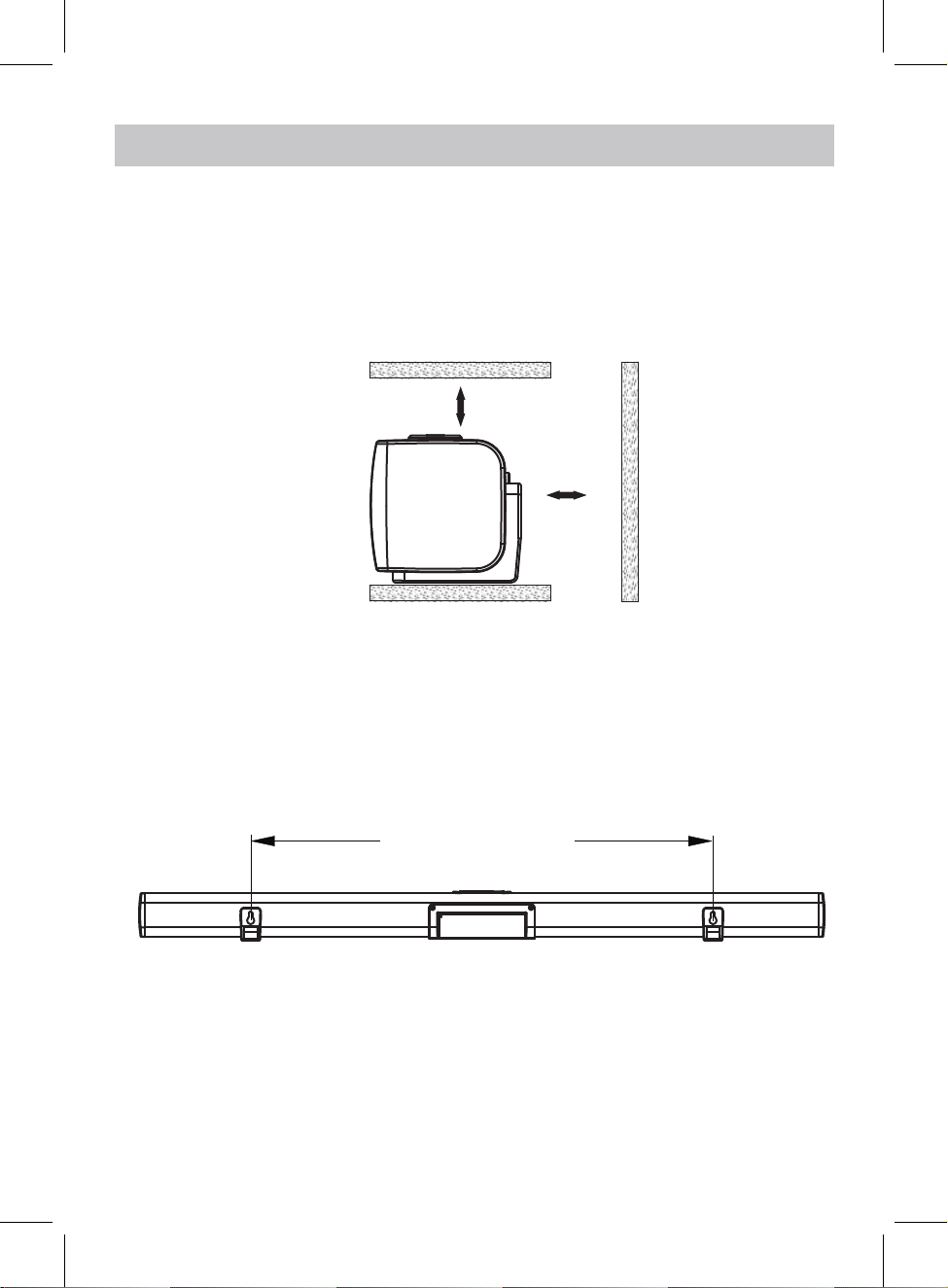
PLACEMENT AND MOUNTING
1. Placing the device on table - Ventilation
When placing the Sound Bar on an entertainment center, bookshelf, or any type of
enclosed space, be sure to allow at least 2-3 inches of space around the Sound Bar for
ventilation. If the Sound Bar is enclosed in a tight space, without ventilation, heat
generated from the Sound Bar could produce a potential heat hazard.
2-3 inches
2-3 inches
2. The Installation Distance
634mm (24.9 inches)
5
Page 6
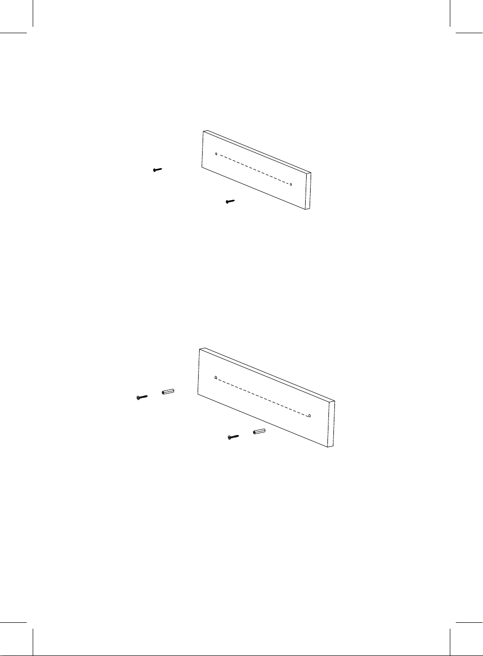
Mounting to a wall
2.1 Mounting to a wooden wall
24.9 inches
A. Mark the position of the mounting screw s on the w all using a pencil(not supplied).
B. Drill the screw s (not supplied) directly into the marks that y ou made on the w all and
leav e approx . 0.3 inch length to hook the sound bar.
C. Put the sound bar onto the mounting screw s. Make sure they are firm and stable.
2.2 Mounting to a brick wall
24.9 inches
A. Mark the position of the mounting screw s on the w all using a pencil(not supplied).
B. Drill 2 holes on mounting positions w ith pow erful electric drill(not supplied).
C. Insert the fix ing plugs and hammer into the holes.
D. Secure the screw s into the fi
sound bar.
E. Put the sound bar onto the mounting screw s. Make sure they are firm and stable.
x ing x . 0.3 inch length to hook the plugs and leav e appro
6
Page 7

PRODUCT OVERVIEW
Front View
Rear View
3. Speaker
AUX IN
4. AUX IN Jack
1. Indicator
2. Remote sensor
OPTICAL
5. OPTICAL Jack
LINE I N
L R
6. LINE IN Jacks
3. Speaker
DC 12V,2 .0A
7. DC IN jack
Top View
8. Standby/Source
button
Standby
/Source
9. SB Pair button
(subw oofer pairing button)
SB Pair
11. Volume up button
Vol+Vol-
10. Volume down button
7
Page 8

Side View of Subwoofer
Rear View of Subwoofer
PRODUCT OVERVIEW
1. Speaker
DC 12V
3. STANDBY Button
2. DC IN Jack
STANDBY
POWER
INDICATOR
4. POWER INDICATOR
8
INDICATOR
5. Pairing Indicator
Page 9

REMOTE CONTROL
1. (Power On/Off) Button
2. AUX Button
1
6
3. LINE IN Button
2
3
AUX
LIN E
IN
OPT ICAL
7
8
9
5. Sound Mode (MUSIC,
TALK, MOVIE, STANDARD)
6. (Mute) Button
4. (Previous) Button
4
10
11
7. (Bluetooth)Button
8. OPTICAL Button
9. (Mode Switch) Button
5
MUSIC
STANDARD
TALK MOVIE
Sound Mode
VOL
12
10. (Next) Button
11. Play/Pause Button
12. (Volume Up/Down)Button
BATTERY INSTALLATION OF REMOTE CONTROL
USING AT FIRST TIME:
Remove and discard the insulation film as Fig.1.
BATTERY REPLACING:
Pull out the battery holder as Fig.2.
Replace the old button cell with a new CR2025 button cell
with the polarity markings facing upward as Fig.3.
Push back the battery holder as Fig.4.
Fig.1
O
P
E
N
Fig.2
3V CR 2025
Fig.3
9
3V CR 2025
O
PE
N
Fig.4
Page 10

BETTERY PRECAUTIONS:
Follow these precautions when using a battery in this device:
1. Use only the size and type of battery specified.
2. Be sure to follow the correct polarity when installing the battery as
ompartment, a reserved battery may cause damage to
c
3. Do not mix different types of batteries together ( e.g: Alkaline and
or old batteries with fresh ones.
4. If the batteries in the device are consumed or the device is not to be used for
remove the batteries to prevent damage or injury from
5. Do not try to recharge the battery
Follow
(
the battery manufacturer’s instructions.)
as it is not intended to be recharged; it can
6. The batteries shall not be exposed to excessive heat such as sunshine or fire
7. Clean the battery contacts and also those of the device prior to battery
8. The remote control
ce
ll battery. If the coin button cell battery is
is supplied with a coin/button
swallowed, it can cause severe internal burns in
just 2 hours and can lead to death. Keep new
and used battery away from children. If the
Battery compartment does not close securely,
stop using the product and keep it away from
children. If you think batteries might have been
swallowed or placed any part of the body, seek
immediate medical attention.
CAUTION
Danger of ex plosion if the batter ly replaced.
y is incorrect
Replace only w ith the same or equiv alent ty pe.
the device.
possible
CR2025
Carbon
leakage.
indicated
-zinc )
period of time,
a long
overheat
.
installation.
in the battery
and rupture.
OPERATION RANGE:
When there is an obstacle betw een the transmitter and the unit, the unit may not operate.
When direct sunlight, an incandescent lamp, fluorescent lamp or any other strong light
shines on the REMOTE SENSOR of the unit, the operation of the remote may be unstable.
16.4 Feet (5M)
AUX
OPTICAL
LINE
IN
MUSIC
TALK MOVIE
Sound Mode
STANDARD
VOL
10
Page 11

GENERAL OPERATIONS
1. Connect the DC 12V, 2.0A Adapter to the DC IN jack on the Main Unit. Plug the
2. Connect the DC 12V, 2.0A Adapter to the DC IN jack on the SUBWOOFER. Plug the
4. After a few seconds, the Main Unit will be connected with SUBWOOFER automatically,
Adapter into the AC outlet with AC100~240V;50/60Hz. The mode indicator on Main Unit
will light up and turn RED.
Adapter into the AC outlet with AC100~240V;50/60Hz. The power indicator on the
SUBWOOFER will light up and turn RED.
3. Press the Standby /Source button on the Main Unit to pow er on the Main Unit.
the pairing INDICATOR on SUBWOOFER will be solid BLUE.
IMPORTANT NOTE: If the pairing INDICATOR on the SUBWOOFER is off, it means
the Main Unit is not connected with the SUBWOOFER successfully. Please operate
as the steps below:
A: Press and hold the SB Pair button on the Main Unit for 3-5 seconds.
B: Press and hold the STANDBY button on SUBWOOFER to power off, then press
the STANDBY button on SUBWOOFER to power on again, the pairing INDICATOR
on SUBWOOFER will blink several times and then turn off, it means the
SUBWOOFER is connected with Main Unit successfully.
C: Press the SB PAIR button on the Main Unit, the pairing INDICATOR on the
SUBWOOFER will be solid BLUE.
5. Press the button on remote control or press the Standby/Source button on the unit
repeatedly to switch to the desired mode.
button on remote control to turn to desired mode, the indicator on front of the unit will
turn to:
Blue...........................................................................................................Bluetooth Mode
Green...........................................................................................................LINE IN Mode
Purple...................................................................................................OPTICAL IN Mode
Indigo(blue+green).......................................................................................AUX IN Mode
Or press the AUX, OPTICAL,
, LINE IN
11
Page 12

6. During Playing:
1. Power on the Main Unit and SUBWOOFER and paired together as previous stated.
~ Press the Vol+ or Vol- button on the unit or press the + or - button on remote control
repeatedly to adjust volume.
~ Press the button on remote control to turn off sound, the mode indicator on the Main
Unit w ill blink, press this button again to resume.
~ Press the MUSIC button on remote control to turn to MUSIC sound effect mode.
~ Press the TALK button on remote control to turn to TALK sound effect mode.
~ Press the MOVIE button on remote control to turn to MOVIE sound effect mode.
~ Press the STANDARD button on remote control to turn to normal sound effect mode.
7. When finish listening, unplu the adapter of the Main Unit and the Subw oofer from AC outlet.
BLUETOOTH OPERATION
2. Press the button on remote control or press the Standby/Source button on Main
Unit repeatedly, or press the button on remote control directly to switch to Bluetooth
mode, the mode indicator on the unit will turn Blue and blink.
3. Power on the external Bluetooth enabled device and enter Bluetooth mode, try
searching the unit.
4. When
" PROSCAN PSB378W "
appears, select it and make connection.
5. After successful pairing, the mode indicator will stop blinking.
6. During playing:
~ Press the or button on remote control to skip tracks.
~ Press the button on remote control to pause, press it again to resume.
7. Press and hold the button on remote control to disconnect current connection
and go into the Bluetooth pairing mode.
NOTE: The unit will be automatically connected with the last connected Bluetooth
device if their Bluetooth
function are activated and they are in working range.
12
Page 13

AUX IN OPERATION
3. Power on the Main Unit and SUBWOOFER and paired together as previous stated.
An external Audio player(such as mobile phone, MP3 player etc.) can be connected
to this unit and listen through the unit's speakers.
1. Plug one end of the AUX IN Cable into the AUX IN jack on the unit.
2. Plug another end of the AUX IN Cable into the headphone jack or Aux Out jack
on the external audio player.
AUX IN
OPTICAL
..............................................
..................................................................................................................
Connect to the Phones; AUX Out;
(Such like MP3 Player; cell phones;
MP3 Player
Mobile Phone
LINE I N
L R
Line Out Jack of the external devices
iPod/iPad ... etc)
DC 12V,2 .0A
..................................................................................................................
..............................................
4. Press the button on remote control or press the Standby/Source button on Main
Unit repeatedly, or press the AUX button on remote control directly to switch to AUX
IN mode, the mode indicator on the unit will turn Indigo(Blue+Green).
5. Power on the connected external player and start playing the music as usual.
13
Page 14

LINE IN OPERATION
3. Power on the Main Unit and SUBWOOFER and paired together as previous stated.
An external Audio/Video player(such as TV, DVD player etc.) can be connected to
this unit and listen through the unit's speakers.
1. Plug one end of the line in cable into the LINE IN jacks(L&R) on the unit.
2. Plug the other end of the line in cable into the Line Out jacks(L&R) on TV or DVD
player etc.
AUX IN
Line out jacks of
TV/DVD player etc.
L R
Video
OPTICAL
white
LINE I N
L R
DC 12V,2 .0A
red
4. Press the button on remote control or press the Standby/Source button on Main
Unit repeatedly, or press the LINE IN button on remote control directly to switch to
LINE IN mode, the mode indicator on the unit will turn Green.
5. Power on the connected external player and start playing the music as usual.
14
Page 15

OPTICAL IN OPERATION
2. Power on the Main Unit and SUBWOOFER and paired together as previous stated.
1. Connect the Optical out jack from the external audio player (such as TV, DVD
player etc.) to the OPT IN jack on the rear of the unit with the optical connection
cable as illustated below:(For PCM format only)
AUX IN
Optical Connection Cable
(not included)
OPTICAL
LINE I N
L R
TV or DVD player etc.
OPTICAL OUT
DC 12V,2 .0A
L
R
Video
3. Press the button on remote control or press the Standby/Source button on Main
Unit repeatedly, or press the OPTICAL button on remote control directly to switch to
OPTICAL IN mode, the mode indicator on the unit will turn Purple.
4. Power on the connected external player and start playing the music as usual.
Turn on the digital audio output and set it to PCM (Pulse Code Modulation) type.
15
Page 16

TROUBLESHOOTING GUIDE
SYMPTOM
No power
No sound or
sound weak
Sound distortion/rattle
POSSIBLE CAUSE
The adapter is not connected
The unit is in power off mode
Volume level in minimum position
The paired/connected device
is not in playback mode
Input source incorrect
Volumelevel too high Reduce the volume level by pressing
POSSIBLE SOLUTION
Connect the adapter to the unit and
wall outlet
Press the Standby/Source button
unit or press the button
control to power on the unit
Raise the volume level by pressing
the Vol+ Button on the unit or the +
button on remote control
Play music/movie in the paired/
connected device as usual and make
sure the volume level of it is in high
level
Press the button
or press the Standby/Source on the unit
to switch to desired mode
the Vol- Button on the unit or press the
- button on remote control
on remote control
on the
on remote
Remote Control
not functioning
Bluetooth
reception failure
Reduce the volume level of the
paired/connected device.
Out of working range
The battery in the remote
control is drained
The external device is
too far from the unit
Have not paired Pair the unit with the BT Device as the
Point the remote control to the
remote sensor on the unit within
16 feet, +/-30 degress
Replace with new battery
Put the externalBT device close to the
unit
procedures stated in this manual.
16
Page 17

SPECIFICATIONS
Power input for main unit and subwoofe................................AC100~240V, 50/60Hz
Power output for main unit and subwoofer..........................DC16V 1.5A
Audio output of the main unit...........................................................................2x10W
Audio output of the subwoofer.........................................................................1x20W
Bluetooth effective working range in open area......................................up to 32 feet
Remote effective working range..............................................................up to 16 feet
PACKAGES
1x Main Unit
1x Subwoofer
1x User Manual
1x Power Adapter
1x Remote Control
1x AUX IN Cable (1M)
1x LINE IN Cable (1.2M)
1x AC/DC Adapter for the Main Unit(DC16V, 1.5A)
1x AC/DC Adapter for the Subwoofer(DC16V, 1.5A)
SPECIFICATIONS AND ACCESSORIES ARE SUBJECT TO CHANGE
WITHOUT NOTICE
For service assistance and product information, please call: 1-800-968-9853.
Curtis International Ltd.
7045 BECKETT DRIVE, UNIT 15, MISSISSAUGA, ON, L5S 2A3 www.curtisint.com
17
Page 18

- English: "
This device complies with Industry Canada licence-exempt RSS standard(
s). Operation is subject to the following two conditions:
(1) this device may not cause interference, and
(2) this device must accept any interference, including interference that
may cause undesired operation of the device."
- French:"
Le présent appareil est conforme aux CNR d'Industrie Canada applicables
aux appareils radio exempts de licence. L'exploitation est autorisée
aux deux conditions suivantes :
(1) l'appareil nedoit pas produire de brouillage, et
(2) l'utilisateur de l'appareil doit accepter tout brouillage radioélectrique
subi, même si le brouillage est susceptible d'en compromettre le
fonctionnement."
 Loading...