

Page 1

37" Bluetooth Soundbar Speaker
MODEL:T-232
Please read this instruction manual carefully and keep it for future reference
Page 2
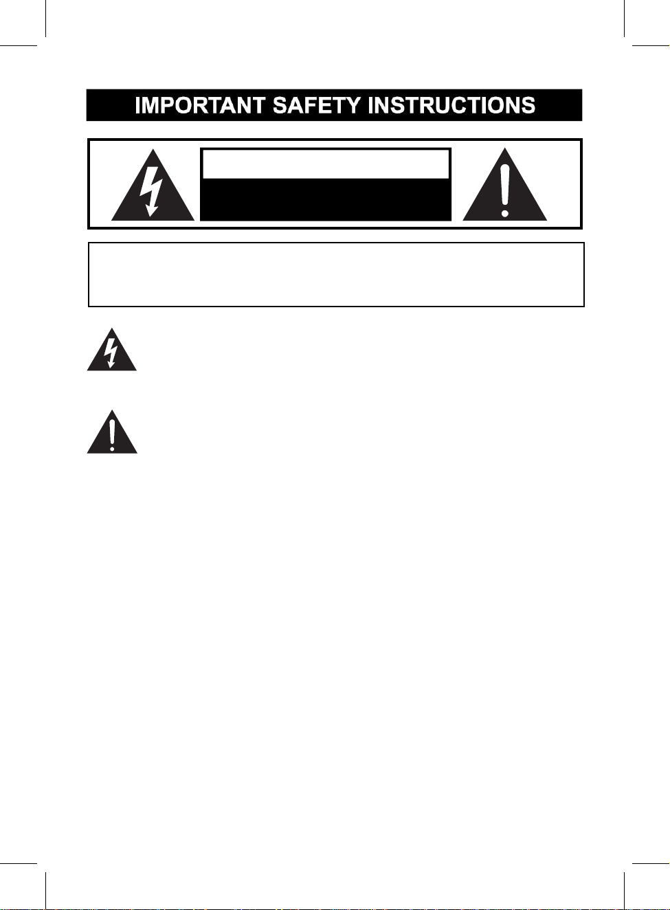
CAUTION
DANGEROUS VOLTAGE:The lighting flash with arrowhead symbol within
an equilateral triangle is intended to alert the user to the presence of
uninsulated “dangerous voltage” within the product’s enclosure that may
ATTENTION:The exclamation point within an equilateral triangle is intended to
alert the user to the presence of important operating and maintenance
(servicing) instructions in the literature accompanying the appliance.
RISK OF ELECTRIC SHOCK
DO NOT OPEN
CAUTION: TO REDUCE THE ELECTRIC SHOCK, DO NOT REMOVE THE
COVER (OR BACK). NO USER SERVICEABLE PART INSIDE, REFER
SERVICING TO QUALIFIED SERVICE PERSONNEL.
be of sufficient magnitude to constitute a risk of electric shock to persons.
W
ARNING:TO PREVENT FIRE OR SHOCK HAZARD, DO NOT EXPOSE
THIS UNIT TO RAIN OR MOISTURE.
WARNING: USE UNDER SUPERVISION OF AN ADULT DUE TO LONG
CORD This unit has a long cord that can be easily tripped on or pulled on,
causing injury. Please make sure it is arranged so that it will not drape over a
tabletop, etc. Where it can be pulled on by children or tripped over accidentally.
FCC STATEMENT:
This device complies with part 15 of the FCC Rules. Operation is subject to the
following two conditions:
(1)This device may not cause harmful interference, and
(2)This device must accept any interference received, including interference
that may cause undesired operation. The antenna(s) used for this transmitter
must be installed to provide a separation distance of at least 20 cm from all
persons and must not be co-located or operating in conjunction with any other
antenna or transmitter.
2
Page 3

1. Read these instructions
2. Keep these instructions
3. Heed all warnings
4. Follow all instructions
FCC NOTICE:
5. Do not use this apparatus near water
This equipment has been tested and found to comply with the limits for a Class
B digital device, pursuant to Part 15 of the FCC Rules. These limits are
designed to provide reasonable protection against harmful interference in a
residential installation. This equipment generates, uses and can radiate radio
frequency energy and, if not installed and used in accordance with the
instructions, may cause harmful interference to radio communications.
However, there is no guarantee that interference will not occur in a particular
installation. If this equipment does cause harmful interference to radio or
television reception, which can be determined by turning the equipment off and
on, the user is encouraged to try to correct the interference by one or more of
the following measures:
●Reorient or relocate the receiving antenna.
●Increase the separation between the equipment and receiver.
●Connect the equipment into an outlet on a circuit different from that to which
the receiver is connected.
●Consult the dealer or an experienced radio/TV technician for help.
FCC WARNING:
To assure continued operation, follow the attached installation instructions and
use only shield cables when connecting to other devices. Changes or
modifications not expressly approved by the party responsible for compliance
could void the user's authority to operate the equipment.
Before using the unit, be sure to read all operating instruction carefully, please
note that these are general precautions and may not pertain to your unit. For
example, this unit may not have the capability to be connected to an outdoor
antenna.
All the safety and operating instructions should be read before the appliance is
operated.
The safety and operating instructions should be kept for future reference.
All warnings on the appliance and in the operating instructions should be
adhered to.
All operation and use instructions should be followed.
The appliance should not be used near water; for example, near a bath tub,
3
Page 4

washbowl, kitchen sink, laundry tub, in a wet basement, or near a swimming
6. Clean only with dry cloth
7. Do not block any ventilation openings. Install in accordance with the
12. Use only with a cart, stand, tripod, bracket, or table
specified by the manufacturer, or sold with the apparatus.
When a cart is used, use caution when moving the
cart/apparatus combination to avoid injury
from tip-over.
13. Unplug this apparatus during lightning storms or when unused for
pool.
The appliance should be cleaned only as recommended by the manufacturer.
manufacturer’s instructions.
Slots and openings in the cabinet and in the back or bottom are provided for
ventilation, to ensure reliable operation of the product and to protect it from
overheating. These openings must not be blocked or covered. The openings
should never be blocked by placing the product on a bed, sofa, rug, or similar
surface. This product should never be placed near or over a radiator or heat
source. This product should not be placed in a built-in installation, such as a
bookcase or rack unless proper ventilation is provided or the manufacturer’s
instructions have been adhered to.
8. Do not install near any heat sources such as radiators, heat registers,
stoves, or other apparatus (including amplifiers) that produce heat.
9. Do not defeat the safety purpose of the polarized or grounding-type
plug. A polarized plug has two blades with one wider than the other. A
grounding type plug has two blades and a third grounding prong. The
wide or the third prong are provided for your safety. If the provided plug
does not fit into your outlet, consult an electrician for replacement of the
obsolete outlet.
10. Protect the power cord from being walked on or pinched particularly
at plugs, convenience receptacles, and the point where they exit from the
apparatus.
11. Only use attachments / accessories specified by the manufacturer.
An appliance and cart combination should be moved with care. Quick stop,
excessive fore and uneven surfaces may cause the appliance and cart
combination to overturn.
long periods of time.
To protect your product from a lightning storm, or when it is left unattended and
unused for long periods of time, unplug it from the wall outlet and disconnect
the antenna or cable system. This will prevent damage to the product due to
lightning and power-line surges.
14. Refer all servicing to qualified service personnel. Servicing is
required when the apparatus has been damaged in any way, such as
power-supply cord or plug is damaged, liquid has been spilled or objects
have fallen into the apparatus, the apparatus has been exposed to rain or
4
Page 5
moisture, does not operate normally, or has been dropped.
15. Power source
This product should be operated only from the type of power source indicated
on the marking label. If you are not sure of the type of power supply to your
home, consult your appliance dealer or local power company. For products
intended to operate from battery power, or other source, refer to the operation
instructions.
16. Power lines
An outside antenna system should not be located in the vicinity of overhead
power lines or other electric light or power circuits, or where it can fall into such
power lines or circuits. When installing an outside antenna system, extreme
care should be taken to keep from touching such power lines or circuits as
contact with them might be fatal.
17. Overloading
Do not overload wall outlets and extension cords as this can result in a risk of
fire or electric shock.
18. Object and liquid entry
Never push objects of any kind into the product through openings as they may
touch dangerous voltage points or short out parts that could result in fire or
electric shock. Never spill or spray any type of liquid on the product.
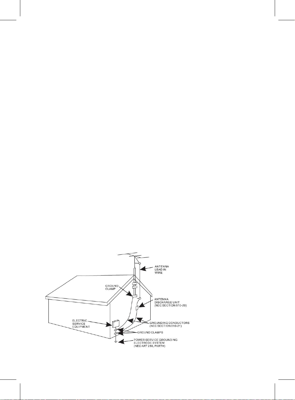
19. Outdoor antenna grounding
If an outside antenna is connected to the product, be sure the antenna system
is grounded so as to provide some protection against voltage surges and built
up static charges. Section 810 of the National Electric Code ANSI/ NFPA 70
provides information with respect to proper grounding of the mast and
supporting structure, grounding of the lead- in wire to an antenna discharge
product, size of grounding conductors, location of antenna- discharge product,
connection to grounding electrodes and requirements for the grounding
electrodes.
5
Page 6

20.
23. Wall or ceiling mounting
Service
Do not attempt to service this product yourself as opening or removing covers
may expose you to dangerous voltage or other hazards. Refer all servicing to
qualified service personnel.
21. Replacement parts
When replacement parts are required, be sure the service technician uses
replacement parts specified by the manufacturer or those that have the same
characteristics as the original parts. Unauthorized substitutions may result in
fire or electric shock or other hazards.
22. Safety check
Upon completion of any service or repairs to this product, ask the service
technician to perform safety checks to determine that the product is in proper
operating condition.
Th
e product should be mounted to a wall or ceiling only as recommended by
the manufacturer.
24. Damage requiring service
Unplug this product from the wall outlet and refer service to qualified service
personnel under the following conditions.
a)When the power- supply cord or plug is damaged.
b)If liquid has been spilled or objects have fallen into the product.
c)If the product has been exposed to rain or water.
d)If the product does not operate normally by following the operating
instructions. Adjust only those controls that are covered by the operating
instructions, as an adjustment of other controls may result in damage and will
require extensive work by a qualified technician to restore the product to its
normal operation.
e)If the product has been dropped or the cabinet has been damaged.
f)When the product exhibits a distinct change in performance- this indicates a
need for service.
25. Note to CATV system installer
This reminder is provided to call the CATV system installer' s attention to
Article 820- 40 of the NEC that provides guidelines for proper grounding and,
in particular, specifies that the cable ground shall be connected to the
grounding system of the building, as close to the point of cable entry as
practical.
NOTE: Refer all servicing to qualified service personnel. Servicing is
required when the unit has been damaged in any way such as the
following: the power-supply cord or plug has been damaged, liquid has
been spilled into unit, the unit has been exposed to rain or moisture, the
unit has been dropped or the unit does not operate normally.
6
Page 7
INSTALLATION
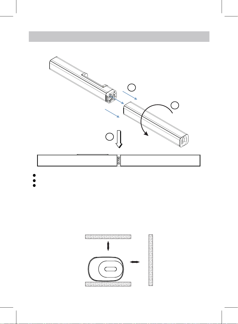
1. Install the Main Unit to Slave Unit
1
Main Unit
3
Step 1: Match and insert the Main Unit to Slave Unit.
Step 2: Turn the Slave Unit as the arrowhead direction in illustration.
Step 3: Make sure both Main Unit and Slave unit fixed firmly.
2
Slave Unit
1.1 Placing on table - ventilation
When placing the Sound Bar on an entertainment center, bookshelf, or any type of
enclosed space, be sure to allow at least 2-3 inches of space around the Sound Bar for
ventilation. If the Sound Bar is enclosed in a tight space, without ventilation, heat
generated from the Sound Bar could produce a potential heat hazard.
2-3inches
2-3inches
7
Page 8

2. The Installation Distance
907.6mm(35.73 inch)
429.6mm(16.9 inch)
2.1 Mounting to a wooden wall
(screws not included)
35.73 inches
A. Mark the position o
B. Drill the screws directly into the marks that you have made on the wall and leave
approx. 0.3 inches length to hook the sound bar.
C. Put the sound bar onto the mounting screws. Make sure they are firm and stable.
f the mounting screws on the wall using a pencil.
2.2 Mounting to a brick wall
35.73 inches
(screws and plastic
fixing plug are not included)
A. Mark the position o
B. Drill 2 holes on wall with a powerful electric drill.
C. Insert the fixing plug and hammer into the holes.
D. Secure the screws into the fixing plug and leave approx. 0.3 inches length to hook
the sound bar.
E. Put the sound bar onto the mounting screws. Make sure they are firm and stable.
f the mounting screws on the wall using a pencil.
8
Page 9

3. Installation to the base
●Install the Main Unit to the base
2
Main Unit
1
Base for Main Unit
Step 1: Match and insert the Main Unit to the Base.
Step 2: Turn the Main Unit as the arrowhead direction in illustration.
Step 3: Make sure Main Unit and Base are fixed firmly.
3
Base
9
Page 10

●Install the Slave Unit to the base
2
Slave Unit
1
Base for Slave Unit
Step 1: Match and insert the Slave Unit to the Base.
Step 2: Turn the Slave Unit as the arrowhead direction in illustration.
Step 3: Make sure Slave Unit and Base are fixed firmly.
3
Base
10
Page 11

Front View
PROdUCT OvERvIEW
Rear View
1
1
2
VOL+
VOL–
3
4
1
1
5
6
SOURCE
AUX I N
DC 16 V
7
USB P LAYER
OPT ICAL
HDM I
8
1. Speaker
2. Remote Sensor
3. VOL+ Button
4. VOL- Button
5. Mode Indicator
6. Play/Pause Button
7. Power/Standby Button
9
10 11
12
13
8. DC IN Jack
9. LINE IN Jacks
10. AUX IN Jack
11. OPTICAL IN Jack
12. USB PLAYER Port
13. HDMI IN Jack
11
Page 12

REMOTE CONTROL
1
2
3
4
5
6
7
8
9
10
11
12
13
14
15
1. POWER Button
2. BT Mode Button
3. USB Mode Button
4. AUX IN Mode Button
5. LINE IN Mode Button
6. Play/Pause Button
7. EQ Button
8. Previous Button
9. VOL- Button
10. MUTE Button
11. OPTICAL Mode Button
12. HDMI Mode Button
13. PAIR Button
14. Next Button
15. VOL+ Button
12
Page 13

BATTERY INSTALLATION OF REMOTE CONTROL
Battery installation:
1.Slide and lift the battery door.
2.Install two “AAA” size batteries into the battery
compartment as indicated by the
3.Close up the battery door.
Battery precaution:
Follow these precautions when using a battery in this device:
1.Warning-Danger of explosion if battery is incorrectly replaced. Replace only with the
same or equivalent type.
2.Use only the size and type of battery specified.
3.Be sure to follow the correct polarity when installing the battery as indicated in the
battery compartment. A reversed battery may cause damage to the device.
4.Do not mix different types of batteries together (e.g. Alkaline and Carbon-zinc) or old
batteries with new ones.
5.If the batteries in the device are completely drained or the device will not be used for a
long period of time, remove the batteries to prevent damage or injury from possible
battery leakage.
6.Do not try to recharge batteries not included to be recharged; they can overheat and
rupture. (Follow battery manufacture’s instructions.)
7.The batteries shall not be exposed to excessive heat such as sunshine, fire or the like.
8.Remove batteries promptly if consumed.
9.Clean the battery contacts, and also those the device, prior to battery installation.
polarity markings.
emote control operation range
R
●
When there is an obstacle between the remote and the transmitter, the unit
●When direct sunlight, an incandescent lamp, fluorescent lamp or any other
shines on the REMOTE SENSOR of the unit, the operation of the
remote may be
13
may not
strong light
unstable.
operate.
Page 14

GENERAL OPERATION
1. Connect the AC/DC adapter to the unit and wall outlet. The source indicator will
turn red.
2. Press and hold the /STANDBY button on the unit or press the button on
remote control to
3. Press the /STANDBY button on the unit repeatedly or press the BT, USB,
OPTICAL, AUX IN, LINE IN or HDMI button on remote
desired mode. The color of source indicator will
Blue.............................................................................................Bluetooth Mode
Indigo(blue+green).................................................................OPTICAL IN Mode
White(red+green+blue).................................................................LINE IN Mode
Violet ............................................................................................AUX IN Mode
Orange(red+green).......................................................................HDMI IN Mode
Green.................................................................................................USB Mode
4. During Playback:
power on the unit.
control to switch to the
turn to:
~ Press the VOL+ or VOL- buttons repeatedly to adjust volume.
~ Press the MUTE button on remote control to turn on or turn off sound.
~ Press the EQ button on remote control repeatedly to set to different EQ mode.
5. When finish listening, press and hold the /STANDBY button on the unit or
press the button
on remote control to put it into
14
standby mode.
Page 15

BLUETOOTH OPERATION
1. Power on the unit as previously explained.
2. Press the /STANDBY button on the unit repeatedly or press the BT button on
remote control, the source indicator will turn Blue and blink.
3. Power on the external Bluetooth enable device and enter Bluetooth mode and try
searching the unit.
4. When " TEWELL T-232 " appears, select it and make connection.
5. After successful paired, the source indicator will stay solid.
6. During playback:
~ Press the or button on remote control to skip tracks.
~ Press the button on the unit or remote control to pause, press it again to
resume playback.
7. Press the PAIR button on remote control to disconnect the current connection.
NOTE: The unit will be automatically paired with the last paired Bluetooth device
if their Bluetooth
function is activated and they are in working range.
15
Page 16

OPTICAL-IN OPERATION
1. Connect the Optical out jack from the external audio player (such as TV, DVD
player etc.) to the OPTICAL IN jack on the rear of the unit with the optical
connection cable as illustated below:(For PCM format only)
AUX I N
DC 16 V
TV or DVD player etc.
OPTICAL OUT
2. Power on the unit as previously explained.
3. Press the /STANDBY button on the unit repeatedly or press the OPTICAL
button on the remote control, the source indicator turns to Indigo
USB P LAYER
OPT ICAL
HDM I
Rear View
(blue+green).
4. Power on the connected external player and start playback the music as usual.
Turn on the digital audio output and set it to PCM (Plus Code Modulation) type
similar to the follows figure:
Picture
Sound Mode Standard
Bass
Treble
Balance
Surround Off
AVL Off
Digital Output PCMDigital Output PCM
Audio Language English
AudioAudio
Select
Time
Setup
Move
Lock
MENU
Off
Exit
16
Page 17

LINE IN OPERATION
An external Audio/Video player(such as TV, DVD palyer etc.) can be connected to
this unit and listen through the unit's speakers.
1. Plug one end of the line in cable into the LINE IN jacks(L&R) on the unit.
2. Plug the other end of the line in cable into the Line Out jacks(L&R) on TV or DVD
palyer etc.
AUX I N
DC 16 V
USB P LAYER
OPT ICAL
HDM I
Rear View
red
white
Line out jacks of
TV/DVD player etc.
LR
Video
3. Power on the unit as previously explained.
4. Press the /STANDBY button on the unit repeatedly or press the LINE IN
button on the remote control, the source indicator turns to
White(red+green+blue).
5. Power on the connected external player and start playback the music as usual.
17
Page 18

AUX IN OPERATION
An external Audio player(such as mobile phone, MP3 palyer etc.) can be connected
to this unit and listen through the unit's speakers.
1. Plug one end of the AUX IN Cable into the AUX IN jack on the unit.
2. Plug another end of the AUX IN Cable into the headphone hack or Aux Out jack
on the external audio player.
AUX I N
DC 16 V
USB P LAYER
OPT ICAL
HDM I
Rear View
MP3 Player
Mobile Phone
Connect to the Phones; AUX Out;
Line Out Jack of the external devices
(Such like MP3 Player; cell phones;
iPod/iPad ... etc)
3. Power on the unit as previously explained.
4. Press the /STANDBY button on the unit repeatedly or press the AUX IN
button on the remote control, the source indicator turns to
Violet.
5. Power on the connected external player and start playback the music as usual.
18
Page 19

HdMI IN OPERATION
An external Audio/Video player(such as TV, DVD palyer etc.) can be connected to
this unit and listen through the unit's speakers.
1. Plug one end of the HDMI cable into the HDMI IN port on the unit.
2. Plug the other end of the HDMI cable into the HDMI IN (ARC) port on TV or DVD
palyer etc.
DC 16 V
HDMI out jacks of
TV/DVD player etc.
LR
Video
HDMI IN (ARC)
Rear View
AUX I N
USB P LAYER
OPT ICAL
HDM I
3. Power on the unit as previously explained.
4. Press the /STANDBY button on the unit repeatedly or press the HDMI
button on the remote control, the source indicator turns to
Orange(red+green).
5. Power on the connected external player and start playback the music as usual.
Explanation:
ARC (Audio Return Channel)
19
Page 20

USB PLAYER OPERATION
1. Power on the unit as previously explained.
2. Press the /STANDBY button on the unit repeatedly or press the USB button
on the remote control, the source indicator turns to Green.
3. Insert an USB Device to the USB PLAYER port on the unit. The unit will
automatically play after a few seconds.
AUX I N
DC 16 V
USB P LAYER
OPT ICAL
HDM I
USB
4. During playback:
~ Press the or button on remote control to skip tracks.
~ Press the button on the unit or remote control to pause, press it again to
resume playback.
20
Page 21

TROUBLESHOOTING
SYMPTOM
No power
No sound or
sound weak
Sound distortion/rattle
POSSIBLE CAUSE
The adapter is not connected
The unit is in standby mode
Volume level in minimum position
The paired/connected device
is not in playback mode
Input source incorrect
Volumelevel too high Reduce the volume level by pressing
POSSIBLE SOLUTION
Connect the adapter to the unit and
wall outlet
Press and hold the /STANDBY button
on unit or
control
Raise the volume level by pressing
the VOL + Button on the unit
Play music/movie in the paired/
connected device as usual and make
sure the volume level of it is in high
level.
the VOL - Button on the unit
or press the button on remote
to power on the unit
Or press VOL+ button on remote control
Press the SOURCE button on unit or
on remote control to switch to desired
mode
Or press VOL- button on remote control
Remote Control
not functioning
Bluetooth
reception failure
Reduce the volume level of the
paired/connected device.
Out of range
Point the remote control to the
remote sensor on the unit within
16 feet, +/-30 degress
The batteries in the remote
Replace with new battery
control are drained
The external device is
too far from the unit
Have not paired Pair the unit with the BT Device as the
Put the external BTdevice close to the
unit.
procedures stated in this manual.
21
Page 22

SPECIFICATIONS
Power input ............................................................................AC100~240V, 50/60Hz
Power output ......................................................................DC16V 1.8A
Audio output ...................................................................................................4x7.5W
Bluetooth effective working range in open area......................................up to 32 feet
Remote effective working range..............................................................up to 16 feet
PACKAGES
1 x Main Unit & Slave Unit
2 x Metal Bases
1 x User Manual
1 x Power Adapter
1 x Remote Control
1 x AUX IN Cable
1 x LINE IN Cable
SPECIFICATIONS AND ACCESSORIES ARE SUBJECT TO CHANGE
WITHOUT NOTICE
is a trademark on a registered trademark of Bluetooth
SIG Inc. All other trademarks and trade names are
those of their respective owners.
22
 Loading...