

Page 1

Stereo Sound Bar System
Stereo Sound Bar System
®
with Bluetooth
with Bluetooth
®
Wireless Technology
Wireless Technology
Owner's Manual
PLEASE READ BEFORE OPERATING THIS EQUIPMENT.
Model: CHT921
Size: 148.5(W) x 210(H)mm (A5)
Page 2
FCC Warnings
WARNING:Changes or modifications to this unit
not expressly approved by the party responsible
for compliance could void the user’s authority to
operate the equipment.
NOTE: This equipment has been tested and
found to comply with the limits for a Class B
digital device, pursuant to Part 15 of the FCC
Rules. These limits are designed to provide
reasonable protection against harmful interference
in a residential installation. This equipment
generates, uses, and can radiate radio frequency
energy and, if not installed and used in
accordance with the instructions, may cause
harmful interference to radio communications.
However, there is no guarantee that interference
will not occur in a particular installation. If this
equipment does cause harmful interference to
radio or television reception, which can be
determined by turning the equipment off and on,
the user is encouraged to try to correct the
interference by one or more of the following
measures:
Reorient or relocate the receiving antenna.
•
Increase the separation between the
•
equipment and receiver.
Connect the equipment into an outlet on a
•
circuit different from that to which the receiver
is connected.
Consult the dealer or an experienced radio/TV
•
technician for help.
FCC NOTICE:
To assure continued compliance, follow the attached
installation instructions and use only shielded cables
when connecting to other devices. Modifications not
authorized by the manufacturer may void user’s
authority to operate this device.
Page 3
Page 4
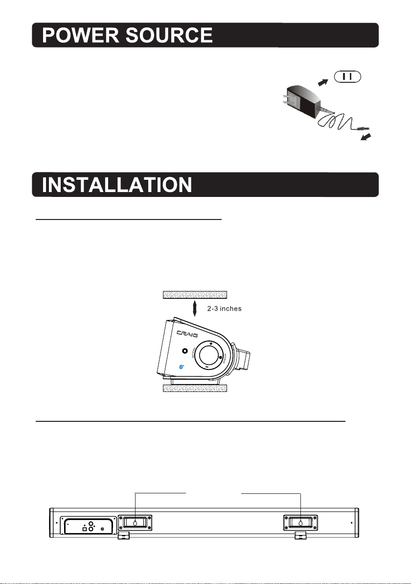
Insert the small plug from supplied AC/DC adaptor to DC IN jack
on the rear of the unit and insert the AC/DC adaptor
to the wall outlet having AC 100-240V~, 50/60 Hz.
NOTE:This AC/DC Adapter is intended to be
correctly orientated in a vertical or floor mount position.
AC/DC adapter
To the DC IN jack on the rear of unit.
1. Placing on the table
When placing the Sound Bar on an entertainment center, bookshelf, or any type of
enclosed space, be sure to allow at least 2-3 inches of space around the Sound Bar
for ventilation. If the Sound Bar is enclosed in a tight space, without ventilation, heat
generated from the Sound Bar could produce a potential heat hazard.
AUX 2
2. Mounting the Speaker Bar onto a wall
We recommend having this speaker professionally mounted. By using the included
wall mounting accessories, the sound bar can be mounted onto a wall.
Distance Between Two Brackets
16.4 inches
3
Page 5
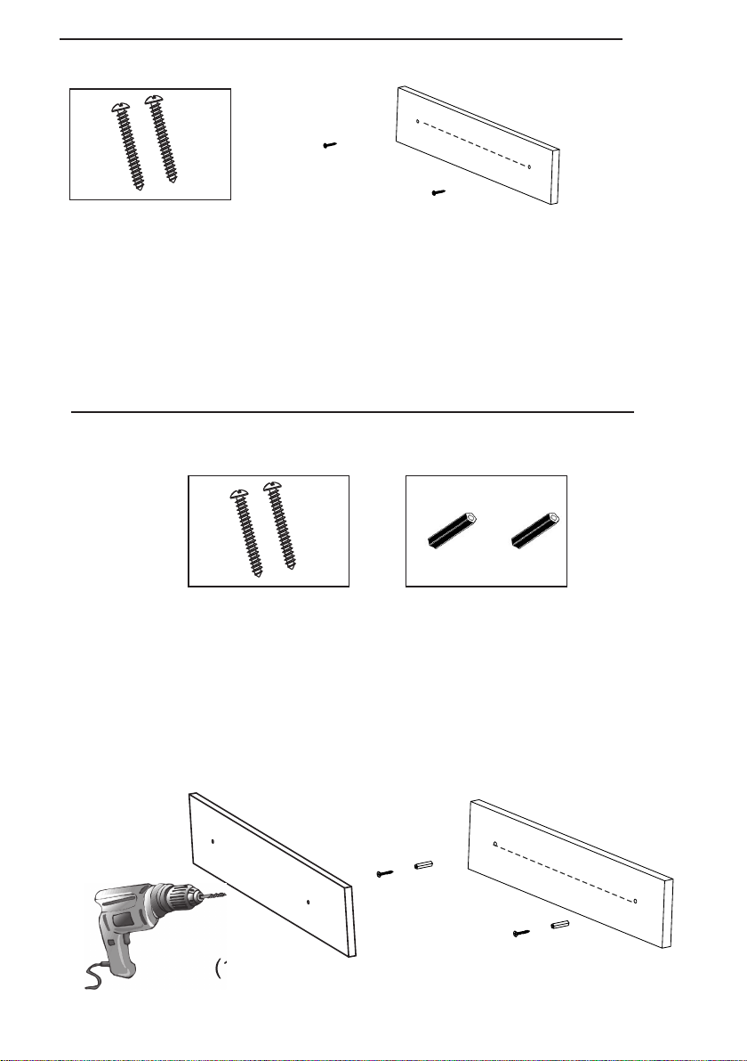
2.1 Mounting on the wooden wall
You may use
16.4 inches
2 pieces screws
(Included)
1. Mark the position of the mounting screws on the wall using a pencil.
2. Drill the supplied screws directly into the marks that you have made on the wall
and leave approx. 0.3 inch length to hook the sound bar.
3. Put the sound bar onto the mounting screws. Make sure they are firm and stable.
2.2 Mounting on the wall
2.2 Mounting on the wooden wall:
You may use
2 pieces screws
(Included)
1. Mark the position of the mounting screws on the wall using a pencil.
2. Drill 2 x 7/32 inch diameter holes by a powerful electric drill ( Not supplied ).
3. Insert the supplied plastic inserts into the holes by hammer .
4. Secure the supplied screws into the plastic insert and leave approx. 0.3 inch
length to hook the sound bar.
5. Put the sound bar onto the mounting screws. Make sure they are firm and stable.
(1)
2 pieces plastic inserts
(Included)
( Not Supplied )
16.4 inches
(2)
4
Page 6
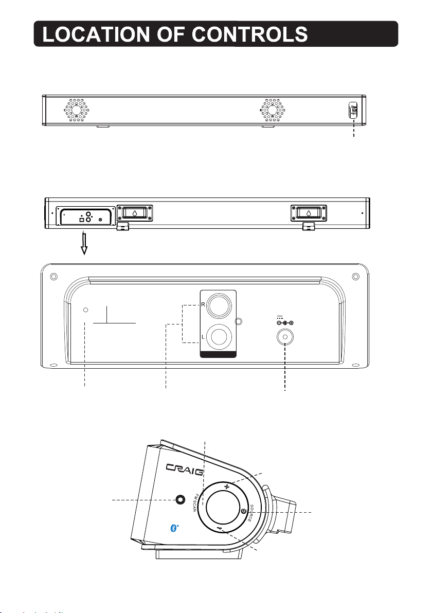
Front View
Back View
Indicator
ANT
ANT (Antenna)
Side View
AUX 2
AUX 1
AUX 2
AUX 1
FM SCAN
5
DC IN
DC 16V,1.8A
DC IN
VOLUME +
VOLUME -
POWER/SOURCE
Page 7
1
8
2
3
4
5
6
7
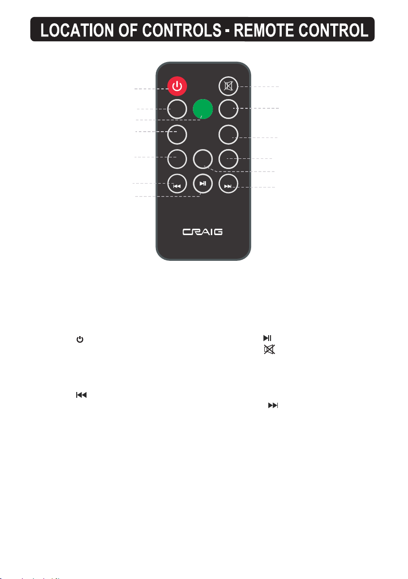
1. Power
2. VOL ( Volume ) -
3. SOURCE
4. BASS -
5. TREBLE -
6. /TUNE -
SOU RCE
EQ
VOL +
TREBLE+
TUN E+
VOL -
BASS- BASS+
TREBLE-
TUN E-
9
10
11
12
13
7.
8. ( Mute )
9. VOL ( Volume ) +
10. BASS +
11. TREBLE +
12. EQ ( Equalizer )
13. / TUNE +
6
Page 8
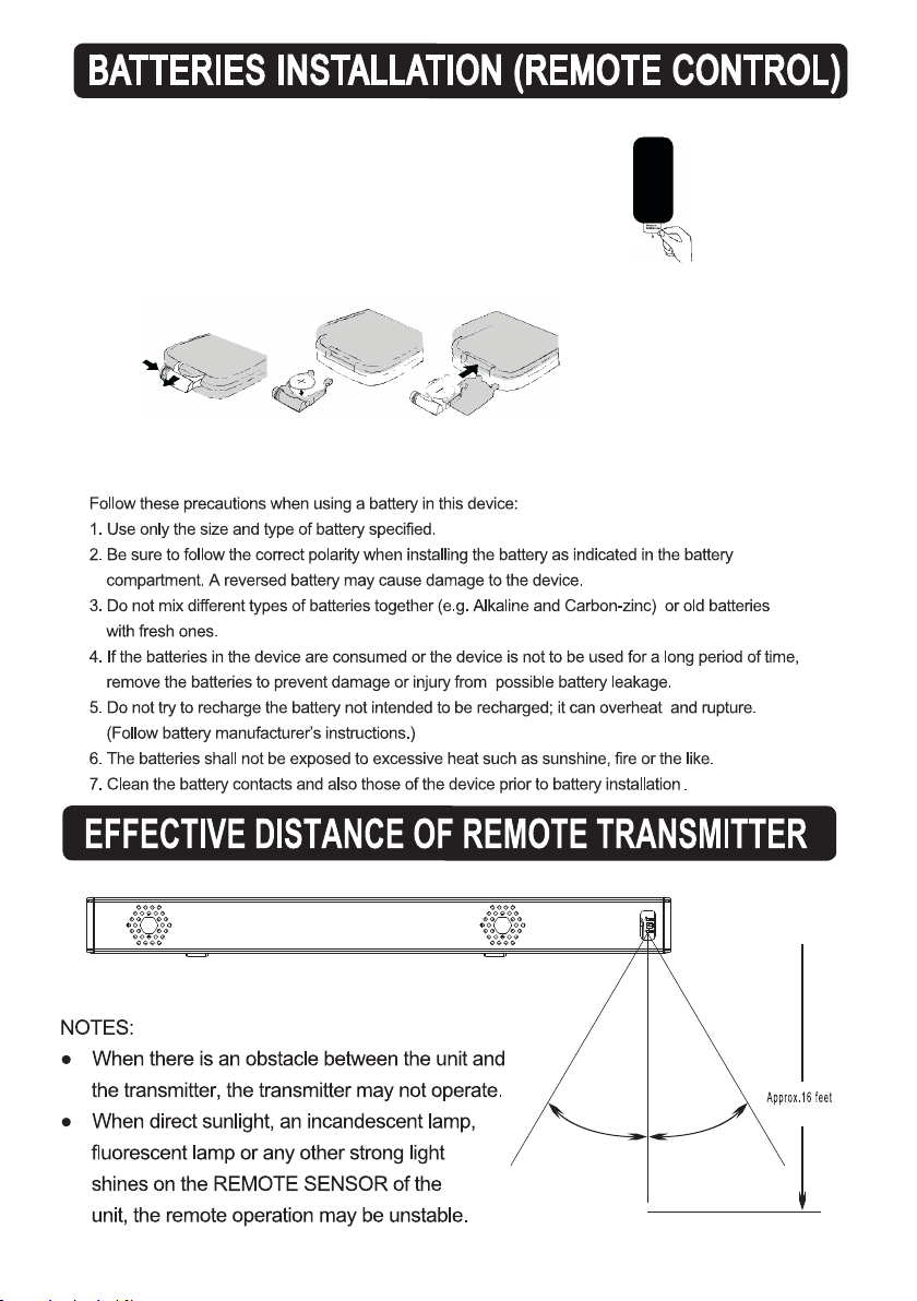
-First Time Use
Remove and discard the insulation tab as figure on the right.
-Replacing Batteries For Remote Control
1. Push and slide out the battery holder as figure 1 below.
2. Replace the battery with a new CR2025 button cell as the polarity
markings on the rear of the Remote Control.
3. Close the battery holder.
Fig.1 Fig.2
BATTERY PRECAUTIONS
Fig.3
Remote Sensor
30
°
30
°
7
Page 9
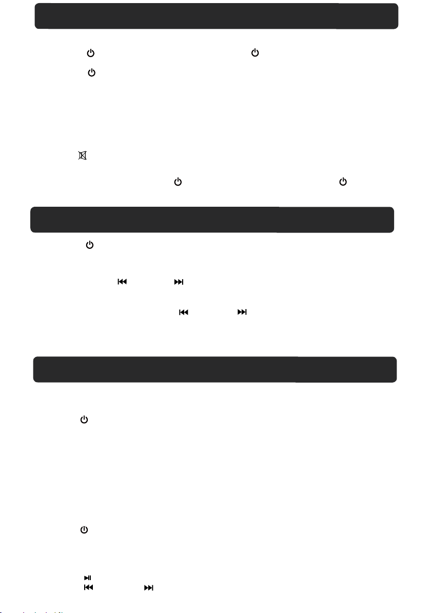
GENERAL OPERATIONS
1. Connect the AC/DC adapter to the unit and wall outlet as the previous procedure.
Indicator will light.
2. Press the Power/SOURCE button on the unit or the Power button on the remote control
to power on the unit from standby mode.
3. Press the Power / SOURCE button on the unit or the SOURCE button on remote control
repeatedly to switch to desired mode.The color of Indicator will turn to corresponding color as below:
~ Blue: BT ( Blue Tooth )
~ Purple: Radio
~ Green: AUX 1
~ Orange: AUX 2
4. During Playback:
~ Press the VOL ( Volume ) +/- buttons to adjust volume level as desired.
~ Press the EQ button repeatedly to select and set equalizer mode as desired.
~ Press ( Mute ) button on the remote control to turn off the sound. Press again to resume.
~ Press the BASS +/- buttons to adjust the sound level of bass.
~ Press the TREBLE +/- buttons to adjust the sound level of treble.
5. When finished listening, press the Power /SOURCE button on the unit or the Power button
on the remote control to power off ( Stanby mode )
6. If long period of time will not use the unit, unplug the AC/DC Adaptor from the wall outlet.
the unit.The color of Indicator will turn Red.
The Red
LISTEN TO FM RADIO
1. Power ON the unit as previous procedures.
2. Press the Power/SOURCE button on the unit or the SOURCE button on the remote control
repeatedly until the color of Indicator turns to Purple.
3. Press the FM SCAN button on the unit to auto search and plays the next availble FM station.
Repeat the same procedures until the desired radio station is searched and play. Or
4. Press and hold the /TUNE - or / TUNE + buttons on the remote control until the indicator
starts blinking. The unit will start to search next ( or previous ) available FM radio station then plays.
Repeat the same procedures until the desired radio station was received and plays.
5. For fine tune, press and release the /TUNE - or /TUNE + buttons repeatedly.
Note: When a FM stereo station was searched, the unit will plays it in stereo mode automatically.
FM Antenna
The Antenna wire on the rear of the unit is for radio reception. If reception is weak, unwind and
extend the wire or relocate the wire to improve the radio reception.
BLUETOOTH PARING AND PLAYBACK
BT ( Blue Tooth )
In first time use or re-pairing to new BT Device, pairing the unit to external BT Device as follows:
In first time use or re-pairing to new BT Device, pairing the unit to external BT Device as follows:In first time use or re-pairing to new BT Device, pairing the unit to external BT Device as follows:
1. Power ON the unit as previous procedures.
2. Press the Power/SOURCE button on the unit or the SOURCE button on the remote control
repeatedly until the color of Indicator turns to Blue and blink.
3. Power on the external BT Device and enter to searching mode.Start
instructions on the external BT Player. After paired,
( For details pairing procedures, please refer
~
Notes:
When the external BT Device searched the unit, our model number
"CHT921" will appear on the display of the external BT Device.
~
Pairing code "0000" may need to enter.
Normal operation after paired:
1. Turn on the BT function of the external BT Device.
2. Power ON the unit as previous procedures.
3. Press the Power/SOURCE button on the unit or the SOURCE button on the remote control
repeatedly until the color of Indicator turns to Blue.
4. Wait a few seconds until the unit paired to the external BT Device automatically.
5. Play the music in the connected BT Device as usual.
6. During playback:
--Press the button to pause; press again to resume normal playback.
--Press the / TUNE - or /TUNE + buttons to skip tracks.
the Indicator will stop blinking.
to the user's manual of your BT Device. )
8
pairing as the on screen
Page 10
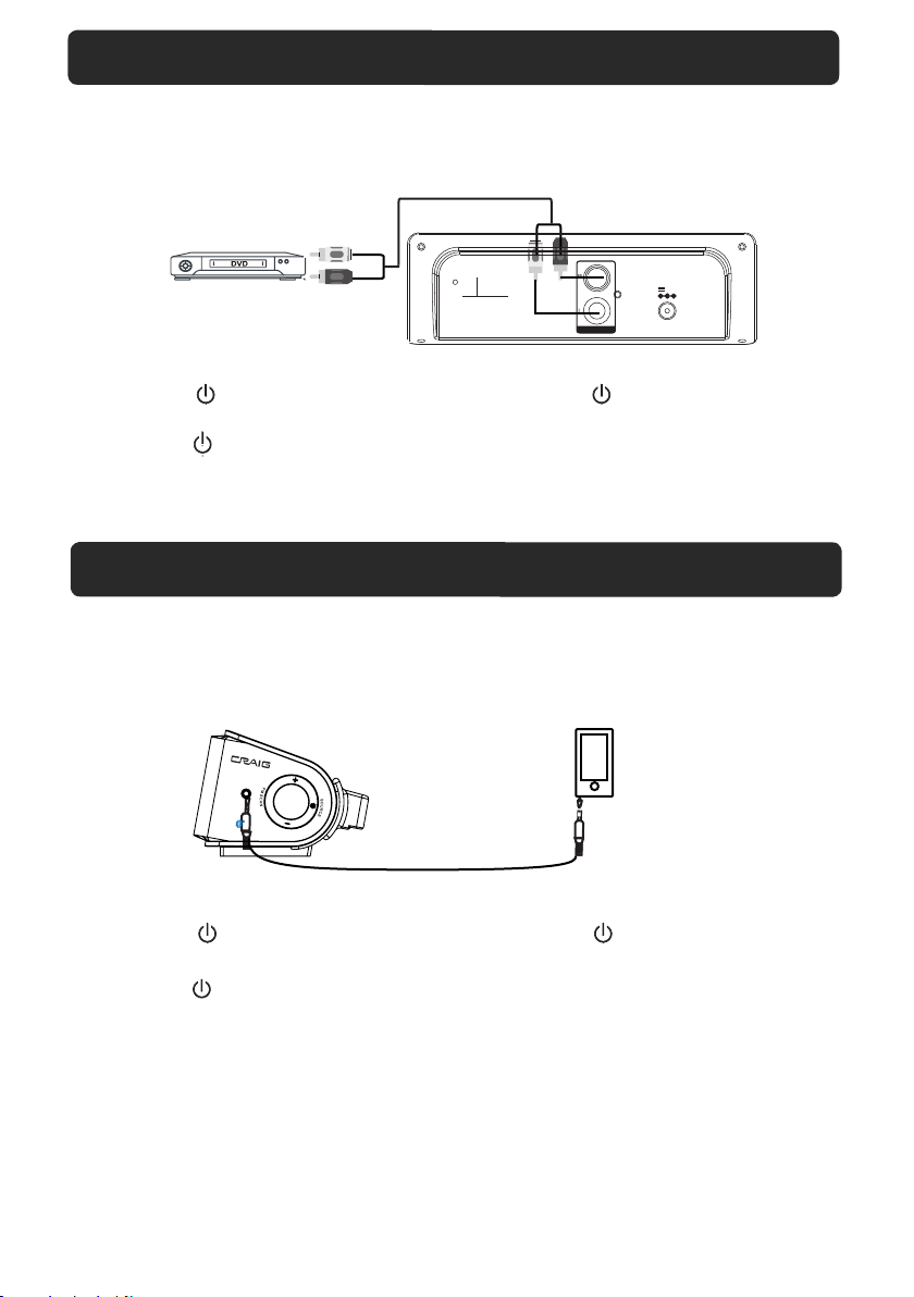
AUX 1 : LISTEN TO TV/DVD/VCR/DVR
1. Connect the Aux out jacks from the external audio player ( such like TV, DVD player
VCR …etc. ) to the AUX 1 jacks on the rear of unit by the supplied RCA Connection
Cable as the figure below:
To Audio Out Jacks
DVD
white
ANT
red
AUX 1
DC IN
DC 16V,
A
1.8
2. Connect the unit to the power as previous procedures.
3. Press the Power/SOURCE button on the unit or the Power button on the
the remote control to power on the unit.
4. Press the Power/SOURCE button on the unit or SOURCE button on remote control
repeatedly until the color of Indictaor turns to Green.
5. Power on the connected external player and start playback music as usual.
AUX 2 : LISTEN TO EXTERNAL AUDIO DEVICES
1. Connect the Headphone/Earphone; Line out jacks from the external audio player
( such like MP3 player; Discman … etc ) to the AUX 2 jack on the Right side of unit
by the supplied Audio Connection Cable as the figure below:
Audio
AUX 2
Player
To Phone Jack
2. Connect the unit to the power as previous procedures.
3. Press the Power/SOURCE button on the unit or the Power button on the
the remote control to power on the unit.
4. Press the Power/SOURCE button on the unit or the SOURCE button on remote
control repeatedly until the color of Indictaor turns to Orange.
5. Power on the connected external player and start playback music as usual.
9
Page 11
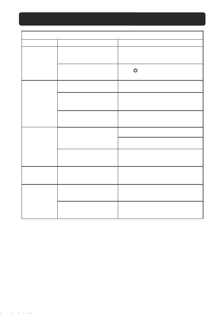
TROUBLESHOOTING GUIDE
Check the followings before requesting service
SYMPTOM POSSIBLE CAUSE POSSIBLE SOULTION
No power
No sound
Sound distortion
Remote not
working
Bluetooth
reception failure
Power AC/DC adapter
not connected
The unit is in Standby mode
Volume in minimum position
The connected device is not
in payback mode
Input source incorrect
Bass level of the connected
device too high
Volume level too high
The battery
The external device is far from
the unit
Have not paired
is consumed
Connect the power AC/DC adapter
Press button to turn on the unit
Raise volume level by pressing the VOL
(Volume) + button
Play the music/movie in the connected
device as usual
volume level of it is in high level
Press the SOURCE button repeatedly to
set the input source to the desired mode
Reduce the bass level of the connected
device.
Press the BASS - button on the Sound Bar
to reduce bass level.
Reduce the volume level by pressing
the
VOL (Volume ) - button
Replace with new battery
Put the external BT device close to the
unit
Pair both units as BT pairing page
and make sure the
10
Page 12
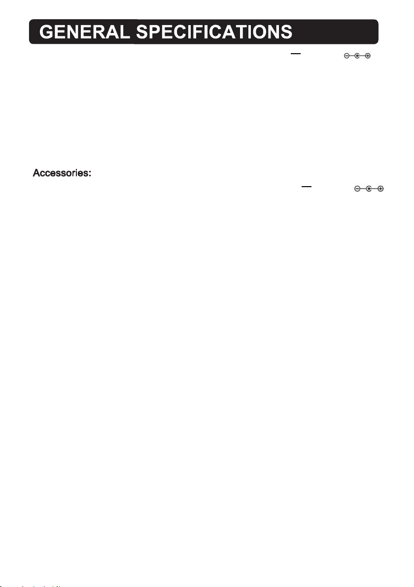
Power Source........................................................................................ DC 16V; 1.8A,
Radio Coverage................................................................................................FM 87.5 -108.0 MHz
Impedance of Speakers:
Loud Speakers .......................................................................................................
Bluetooth Effective Range in Open Aera......................................................................Up to 32 feet
Remote Effective Range.............................................................................................Up to 16 feet
---
8 Ohm, 15W x 2
1 x AC/DC Adaptor ( Input: AC 100-240V~ 50/60Hz; 1A Max.
1 x Remote Control, using CR 2025 button cell ( Included, already installed in remote control )
1 x Stereo Audio Connection Cable with 3.5mm stereo plugs
1 x User's Manual
1 x RCA Connection Cable
2 x Plastic Inserts ( For Wall Mount )
2 x Metallic Screws ( For Wall Mount )
Output: DC 16V; 1.8A, )
---
11
Page 13

LIMITED WARRANTY
Craig warrants this product to be free from manufacturing defects in material and
workmanship under normal use for a period of 90 days from date of purchase. If service
is required, please return the product to the store where it was purchased for exchange;
or, pack the unit in the original packing material with all accessories if applicable, a copy
of your sales receipt and a Cashier’s check or Money Order for $15.00 (to cover shipping
and handling costs) payable to Craig Electronics Inc. For consumers in Canada, please
make sure that the cashier check or money order is redeemable through a U.S. bank.
Ship your product freight pre-paid. Your unit will be repaired, replaced or if the unit can
not be repaired or replaced, a refund will be forwarded to you within four weeks of receipt
of your unit. Please ship your unit to:
Craig Electronics Inc.
1160 NW 163 Drive
Miami, Fl 33169
This warranty is void if the product has been: a) Used in a commercial application or
rental. b) Damaged through misuse, negligence, or abuse. c) Modified or repaired by
anyone other than an authorized Craig service center. d) Damaged because it is
improperly connected to any other equipment.
Note: This warranty does not cover: a) Ordinary adjustments as outlined in the Owner’s
Manual which can be performed by the customer. b) Damage to equipment not properly
connected to the product. c) Any cost incurred in shipping the product for repair. d)
Damage to the product not used in the USA.
This warranty is not transferable and only applies to the original purchase. Any implied
warranties, including the warranty of merchantability, are limited in duration to the period
of this expressed warranty and no warranty whether expressed or implied shall apply to
the product thereafter.
Under no circumstance shall Craig be liable for any loss or consequential damage arising
out of the use of this product. This warranty gives specific legal rights. However, you may
have other rights which may vary from state to state. Some states do not allow limitations
on implied warranties or exclusion of consequential damage. Therefore, these
restrictions may not apply to you.
To Obtain Service on your Product
email:[email protected]
Printed in China CHT921_WC_E0CL4_H0US
Size: 148.5(W) x 210(H)mm (A5)
 Loading...