

Page 1

User’s Manual
© Copyright 2004 Juniper Systems, Inc. ® Juniper Systems, Inc. and
Allegro Field PC are registered trademarks; TM LandMark CE and
Allegro CX are recognized trademarks of Juniper Systems, Inc.
LandMark CE User’s Manual 1
Page 2

Part number: 14653-01
Release Date: August 2005
Editor: R. Timothy
2 LandMark CE User’s Manual
Page 3

Table of Contents
Chapter 1
Introduction ....................................................... 5
Welcome ...................................................................................6
Features ...................................................................................7
Software License Agreement ...................................................8
Chapter 2
Installation ......................................................... 9
First Time LandMark CE Installation ......................................10
Additional LandMark CE Installations .....................................16
Uninstalling LandMark CE ......................................................18
Chapter 3
Using LandMark CE ........................................ 19
Introduction and Operation .....................................................20
GPS Screen ...........................................................................24
Navigation Screen ..................................................................31
Confi guration Screen ..............................................................35
Waypoint Screen ....................................................................50
Chapter 4
Troubleshooting .............................................. 57
Error Messages and Warnings ...............................................58
Chapter 5
Programmers Guide ....................................... 69
Programming LandMark CE ...................................................70
Index ............................................................... 79
LandMark CE User’s Manual 3
Page 4

4 LandMark CE User’s Manual
Page 5

Chapter 1
Introduction
Welcome
Features
Software License Agreement
LandMark CE User’s Manual 5
Page 6

Welcome
We would like to welcome you as a user of LandMark CE, a GPS
Receiver Utility™ software program. LandMark CE is designed to
serve as the interface between a GPS receiver connected to an Allegro
Field PC, and an application program.
Recognizing the need of custom and third party application software
for real-time GPS data streams, Juniper Systems has developed this
utility program to manage the GPS receiver connectivity functions.
We have focused on providing software capable of performing tasks
often used by fi eld personnel in agriculture and natural resources
markets.
GPS services used by fi eld personnel include:
Navigation
Offset capabilities on marked waypoints
Tracking prescribed routes
Marking (recording) location and elevation of specifi c points
LandMark CE runs concurrently with your main data collection and
processing programs. By using a “Hot Key”, your GPS data are sent
directly into whatever application you are currently working with.
If you have any questions or comments about LandMark CE
after reviewing this manual, please feel free to contact our Sales
Department at (435) 753-1881, or visit our website at:
www.junipersys.com.
6 LandMark CE User’s Manual
Page 7

Features
Connects with a wide variety of GPS receivers using the NMEA
data streams.
Multiple data interfaces to other programs running concurrently.
Shared memory, data exchange fi le, and wedging your GPS
data into other programs using a Hot Key are options for data
interface.
Sky plot and satellite signal strength bars keep you informed of
GPS status and quality.
Navigation screen allows you to select To and From waypoints.
Features include: a compass ring depicting direction of travel;
an arrow designating direction to destination; and data fi elds
showing distance to go, speed, track, and bearing along with
cross-track error.
Multiple user selectable waypoint fi les, 256 waypoints per fi le.
The number of waypoint fi les are only limited by the available
data storage on the fi eld computer.
Marking waypoint feature provides the option to average a user
specifi ed number of fi x readings.
Hot key, user specifi ed, for triggering a Mark at any point in time;
this key remains hot regardless of which application is active.
Settable serial interface parameters, supporting GPS receiver
input through any of the hardware COM ports, including
Bluetooth.
User selectable datums and display units (statute, metric,
standard (U.S. feet), nautical).
Diagnostics dialogue screen that displays received NMEA data
strings, which are helpful when connecting a GPS receiver.
Toggle switch F10 connects / reconnects any Allegro Com Port.
Bluetooth Com Port usage auto detection, loads Bluetooth
receiver by default if set as a “favorite” when more than one
device is available.
Bluetooth auto reconnect, LandMark CE automatically trys to
reconnect up to three times when a Bluetooth connection is lost.
Bluetooth PC card power saver, LandMark CE registers with
the Bluetooth stack to the GPS receiver status when it is loaded
or unloaded. This reduces time to reload when coming out of
suspend and auto connects when the stack is reloaded.
LandMark CE User’s Manual 7
Page 8

Software License Agreement
Manufacturer Agreement
▲
This Software License Agreement is between the end-user and the
manufacturer (Juniper Systems, Inc.) Please read the following terms
and conditions before using LandMark CE for use with the Allegro.
This agreement supersedes any prior agreement, written or oral.
Granting of License
The manufacturer grants, under the following terms and conditions,
a non-exclusive license to use the LandMark CE software.
Ownership
Juniper Systems, Inc. retains the title to and ownership of the
software plus any copies made of the software.
Software Use
The software is authorized for use on the Allegro Field PC. You can
use the software on one Field PC at a time per licensed copy. You
may make one copy of the software to be stored as a backup.
Copyright
The LandMark CE software is copyrighted by Juniper Systems, Inc.
You may not rent, lease, lend, sub-license, modify, or disassemble
these programs. The associated documentation may not be copied
without written permission.
Term
This License is in effect until terminated. It will be terminated under
the following conditions:
You destroy all copies of the software and documentation.
You return all copies of the software and documentation to us.
You fail to comply with any provisions of the License Agreement.
Acceptance or Disagreement
Use of the software in any manner indicates your acceptance and
acknowledgment of the terms and conditions of this agreement.
If you do not agree with any of the terms and conditions, do
not use the software. Return the disk and documentation to the
manufacturer. If the software was installed on the Field PCs at the
factory, you must delete it.
8 LandMark CE User’s Manual
Page 9

Chapter 2
Installation
First Time LandMark CE Installation
Additional LandMark CE Installations
Uninstalling LandMark CE
LandMark CE User’s Manual 9
Page 10
First Time LandMark CE Installation
To install LandMark CE on your Allegro it must be installed to
your desktop PC fi rst. After being installed on your desktop PC,
LandMark CE is installed on your Allegro through ActiveSync
connection between your handheld and your PC.
Step 1: Installing LandMark CE on the desktop PC
▲
To install LandMark CE on your Allegro, complete the following
steps:
Establish an ActiveSync connection between your desktop PC
1)
and your Allegro.
Place the LandMark CE CD-ROM into the CD drive of your
2)
desktop PC. The installation wizard automatically starts up with
the LandMark CE Setup: License Agreement screen.
Click on the I Agree button to continue with the installation
3)
process. Note: You must agree with the License Agreement to use
LandMark CE.
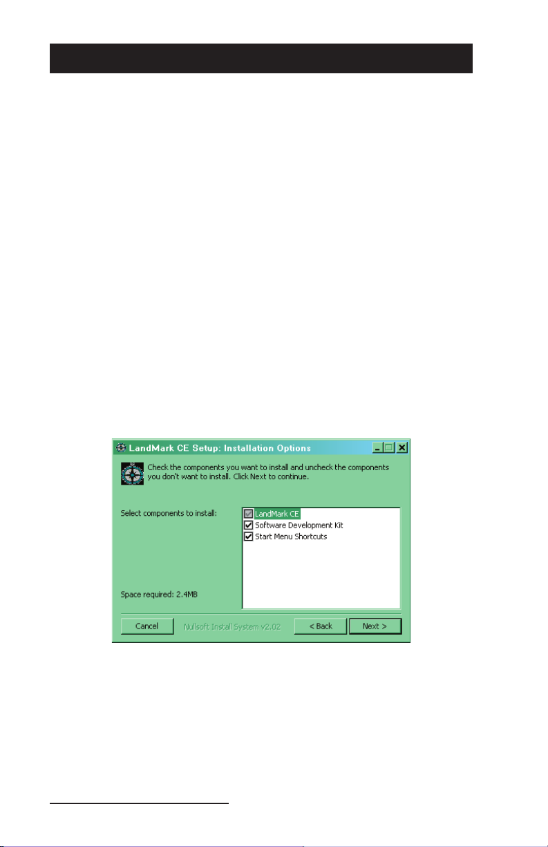
Select the Installation Options you want from the LandMark CE
4)
Setup: Installation Options screen. The installation options are
described below.
The LandMark CE option is selected by default and cannot be
unselected. This installs the LandMark CE application and the
User’s Manual on your desktop PC.
The Software Development Kit (SDK) option is selectable. This
option installs the SDK in the SDK folder where LandMark CE
is installed on your desktop PC. The SDK is used by program
developers.
10 LandMark CE User’s Manual
Page 11
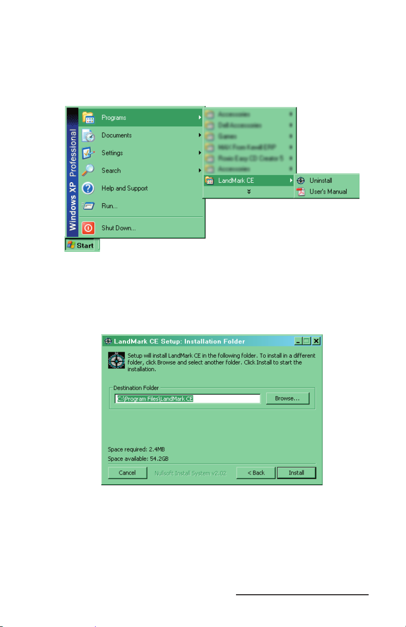
The Start Menu Shortcuts option is a selectable. This option places
a LandMark CE folder located in the Programs folder of your
Start Menu. Inside the LandMark CE folder is the Land Mark CE
Uninstall program and the LandMark CE User’s Manual, which
is a .pdf fi le.
Note: Acrobat Reader is required to open the User’s Manual .pdf.
Select the location on your desktop PC that you want LandMark
5)
CE installed. The LandMark CE folder created in the Program
Files folder on your desktop PC is the default location. If this
location is suffi cient, click on the Install button.
If you want the LandMark CE folder placed in a different
location, click on the Browse button and select the location where
you want LandMark CE installed. Then click on the Install
button.
Wait until LandMark CE installs on your desktop PC. The
6)
LandMark CE Setup: Installing screen appears showing a
progression bar as the application installs.
LandMark CE User’s Manual 11
Page 12
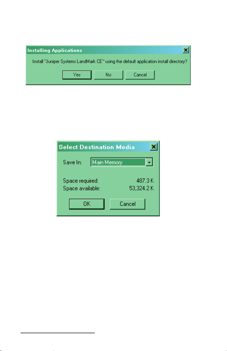
After LandMark CE is installed on your desktop PC, the following
message appears if the Allegro is connected to the desktop PC
through ActiveSync:
Clicking on the Ye s button continues the installation of LandMark
CE onto your Allegro to the default application install directory. The
default folder is C_Drive\Program Files.
Note: We recommend that you click on the Yes button and install
LandMark CE to the default application install directory.
Clicking on the No button opens the following window:
This screen allows you to save LandMark CE in one of the locations
that is displayed in the drop-down Save In: box. These locations are
Main Memory, C_Drive, and Network.
Note: It is highly recommended to install LandMark CE on the
Allegro’s C_Drive.
Tap on the location you want LandMark CE saved to and click on
OK to save your selection. Click on the Cancel button to exit out of
this screen with out saving your selection.
12 LandMark CE User’s Manual
Page 13
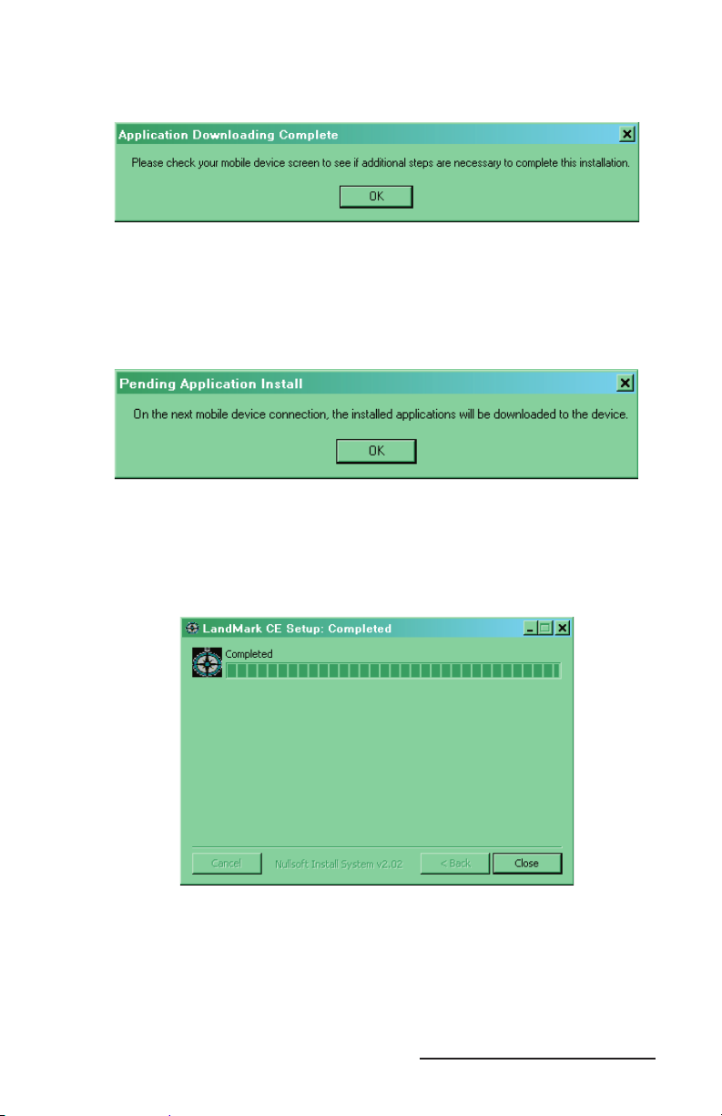
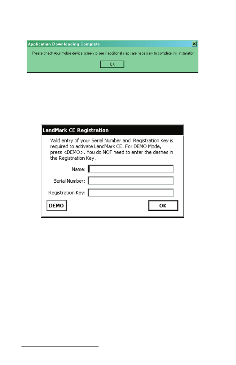
After a install destination is confi rmed, the following message box
pops up:
This screen directs you to fi nish the installation on the Allegro. Click
on OK and proceed to Step 2: Installing LandMark CE on the Allegro
to complete the installation.
If the Allegro is not connected to the desktop PC through ActiveSync,
the following message box appears:
This screen indicates that the next time your Allegro connects to the
desktop PC that the installation of LandMark CE to the Allegro will
be completed. Click on the OK button. The following screen appears
to confi rm that the installation of LandMark CE onto your desktop
PC is complete.
Step 2: Installing LandMark CE on the Allegro
▲
Once LandMark CE is installed on your desktop PC, the installation
process is continued on the Allegro. LandMark CE is installed on to
the Allegro from the desktop PC through an ActiveSync connection.
The following steps are done on your Allegro.
LandMark CE User’s Manual 13
Page 14
When the following screen appears on your desktop PC, an install
progression bar appears in a window on the screen of your Allegro.
After the installation of LandMark CE is completed on your Allegro,
the Registration screen appears.
LandMark CE Registration Screen
LandMark CE is a licensed application and requires a Serial Number
and Registration Key to completely activate the program.
Name
The Name box is used to identify who purchased the program. This
can be either an individual or a company name.
Serial Number
The Serial Number is located on the label located on the LandMark
CE CD-ROM case. This unique number is specifi c to the label on
LandMark CE.
Registration Key
The Registration Key is located on the label located on the LandMark
CE CD-ROM case.
After you have entered the required information, tap on the OK key.
LandMark is now fully installed and registered on your Allegro and
is ready to use.
14 LandMark CE User’s Manual
Page 15
Save System
After you have installed LandMark CE on your Allegro, we
recommend that you perform a Save System utility on your Allegro.
To save the system on your Allegro, complete the following steps:
Tap on Start | Programs | Utilities | Save System.
1)
Wait for the registry on your Allegro to save and for Save System
2)
screen to close.
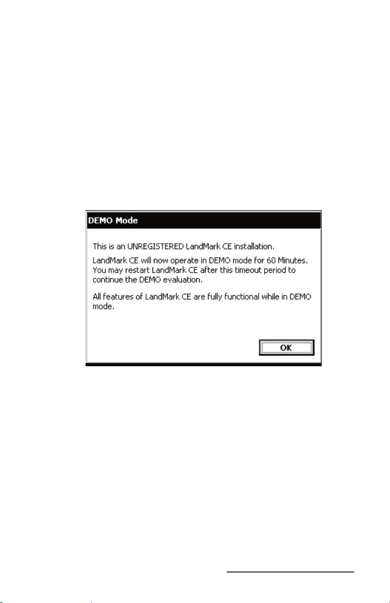
LandMark CE DEMO Mode
LandMark CE offers a Demo Mode allowing you the opportunity
to use LandMark CE for a trial period to evaluate if the program is
compatible with your needs.
Click on the DEMO button to activate Demo mode.
Demo mode allows the user full use of LandMark CE for a 60 minute
period. Once the 60 minutes expires, a pop-up window appears
indicating the 60 minute evaluation session is over.
Tapping on the OK button or the X in the top right corner of this
window saves the LandMark CE fi les you are working on and closes
down the LandMark CE application.
LandMark CE User’s Manual 15
Page 16
Additional LandMark CE Installations
Once LandMark CE has been installed on your desktop PC it does
not need to be reinstalled each time you want to install LandMark
CE on additional Allegro’s. You will need a seperate Serial Number
and Registration Key for each copy of LandMark CE you put on each
Allegro.
To install LandMark CE onto an Allegro from a desktop PC that
already has LandMark CE installed on it, complete the following
steps:
Establish an ActiveSync connection between the Allegro and
1)
desktop PC.
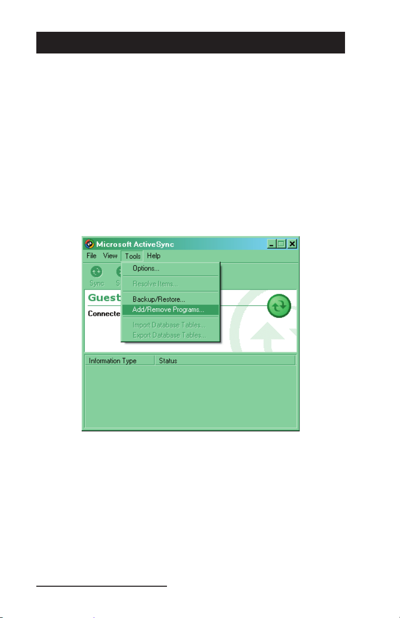
Click on the Tools option in ActiveSync and tap on Add/Remove
2)
Programs.
The Add/Remove Programs screen appears with a list of items on
your desktop PC that are available to install on the Allegro.
16 LandMark CE User’s Manual
Page 17
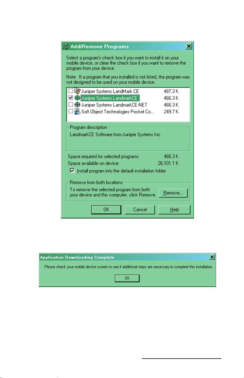
Select the Juniper System LandMarkCE option so a checkmark
3)
appears next to option.
Click on the OK button to proceed with the installation.
4)
After a install destination is confi rmed, the following message
box pops up:
This screen directs you to fi nish the installation on the Allegro.
Click on OK and proceed to Step 2: Installing LandMark CE on the
5)
Allegro to complete the installation.
LandMark CE User’s Manual 17
Page 18

Uninstalling LandMark CE
Since LandMark CE is installed on the desktop PC and the Allegro,
the process for uninstalling the application varies depending on
which device you are uninstalling LandMark from. The following
sets of instructions are device specifi c, use the one that address your
your uninstall request.
Uninstalling LandMark CE from the Desktop PC
▲
To uninstall LandMark CE from your desktop PC, perform one of the
following procedures:
Click on the Start button and go to Settings | Control Panels.
Double-click on the Add/Remove Programs icon. Select LandMark
CE and click on the Remove button.
Click on the Start button and go to Programs | LandMark CE |
Uninstall. Follow the directions in the uninstall wizard.
Uninstalling LandMark CE from the Allegro
▲
To uninstall LandMark CE from your Allegro, perform the following
procedure:
Tap on the Start button and go to Settings | Control Panels.
Double- tap on the Remove Programs icon. Select Juniper Systems
LandMark CE and tap on the Remove button.
18 LandMark CE User’s Manual
Page 19

Chapter 3
Using LandMark CE
Introduction and Operation
GPS Status Screen
Navigation Screen
Confi guration Screen
Waypoint Screen
LandMark CE User’s Manual 19
Page 20

Introduction and Operation
After LandMark CE is installed, you can operate it in the fi eld or
offi ce. This chapter describes the operation, screens, and specifi c
features of the program.
To begin using LandMark CE, double-tap on the LandMark CE
desktop icon. A splash screen displaying LandMark CE A GPS
Receiver Utility and the version number are displayed for two
seconds. The program opens to the following screen:
Screen Selection
▲
The top of initial program screen allows you to select between the
different operation screens that LandMark CE offers.
Gps = GPS Screen
Nav = Navigation Screen
Cnf = Confi guration Screen
Wpt = Waypoint Screen
20 LandMark CE User’s Manual
Page 21

Keyboard Options
▲
To navigate through LandMark CE, use a stylus and tap on the
screen, or press the following keys on the Allegro:
Key Open Screen
F1 GPS Screen
F2 Navigation Screen
F3 Confi guration Screen
F4 Waypoint Screen
F10 COM Port Connect/Disconnect
Navigate within each screen by using the circular arrow key located
in the center of the keyboard.
Use the Ta b key for cursor movement between fi elds. When you
are in the desired fi eld, press Enter to select whatever you have
highlighted.
Alt activates the File drop-down menu, and Spacebar checks or
unchecks a box when a dotted line surrounds it.
Press Esc to exit any screen.
F10 ( Com Port Functionality)
LandMark uses F10 as a toggle switch to connect and reconnect the
Com Port. The F10 toggle function works on all the COM Ports that
LandMark CE can connect to. This functionality allows COM Ports
to be manually disconnected and reconnected without having to
close and re-start LandMark CE.
▲
File
The File option is available on the GPS, Navigation, and Waypoint
screen. Tap on File to activate the following drop-down menu.
New
The New option allows you to create a new waypoint fi le.
LandMark CE User’s Manual 21
Page 22
Open
The Open option allows you to open an existing waypoint fi le.
Convert Waypt File
The Convert Waypt File allows you to convert a waypoint fi le into a
data fi le. It may be necessary to convert a waypoint fi le for viewing
in a different application. We recommend that if you need to
convert a waypoint fi le that you do so only after the waypoint fi le is
completed and all necessary data is collected.
GPS Connect
The GPS Connect option is only available when using Bluetooth with
your GPS receiver. This option connects the GPS receiver through a
Bluetooth connection.
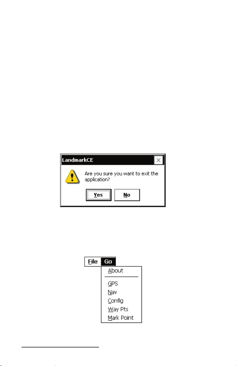
Exit
The Exit option exits you out of the LandMark CE program. After
selecting Exit you receive the following confi rmation screen:
Tap on Ye s to continue to Exit out of LandMark CE or tap on No to
cancel the Exit process.
Go
▲
The Go option is available on the GPS, Navigation, and Waypoint
screen. Tap on Go to activate the following drop-down menu.
22 LandMark CE User’s Manual
Page 23
About
The About option opens a pop-up screen that displays the LandMark
CE version number and date the version was completed.
GPS
Tapping on the GPS option opens the GPS screen.
Nav
Tapping on the Nav option opens the Navigation screen.
Confi g
Tapping on the Confi g option opens the Confi guration screen.
Way Pts
Tapping on the Way Pts option opens the Waypoint screen.
Mark Point
Tapping on the Mark Point option opens the Mark Point screen.
LandMark CE User’s Manual 23
Page 24
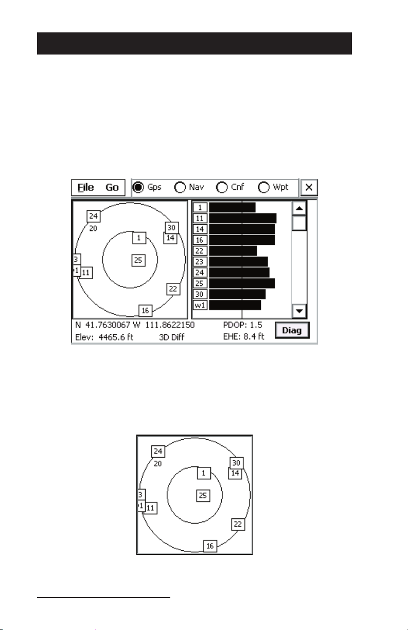
GPS Status Screen
The GPS status screen displays a skyplot that shows the position
of each satellite transmitting GPS data. This screen also helps you
determine how accurate the GPS readings are. To display the GPS
Screen, complete one of the following steps:
Tap on the GPS option at the top of the menu bar.
Tap on Go to access a drop-down menu and select GPS.
Press F1 on the Allegro keyboard.
The Skyplot is on the left side of the screen and displays the
approximate locations of the visible GPS satellites. Your position is
located at the center of the inner circle. The outer circle represents the
fl at or horizon of where you are standing. The inner circle represents
the area above you, this circle has a 60 degree incline from the outer
circle.
24 LandMark CE User’s Manual
Page 25
When a satellite rises above the horizon, the GPS receiver can then
receive a positioning signal from the satellite. The satellite then
appears in the skyplot section of the GPS screen. GPS readings are
more accurate when the satellites are more scattered across the sky.
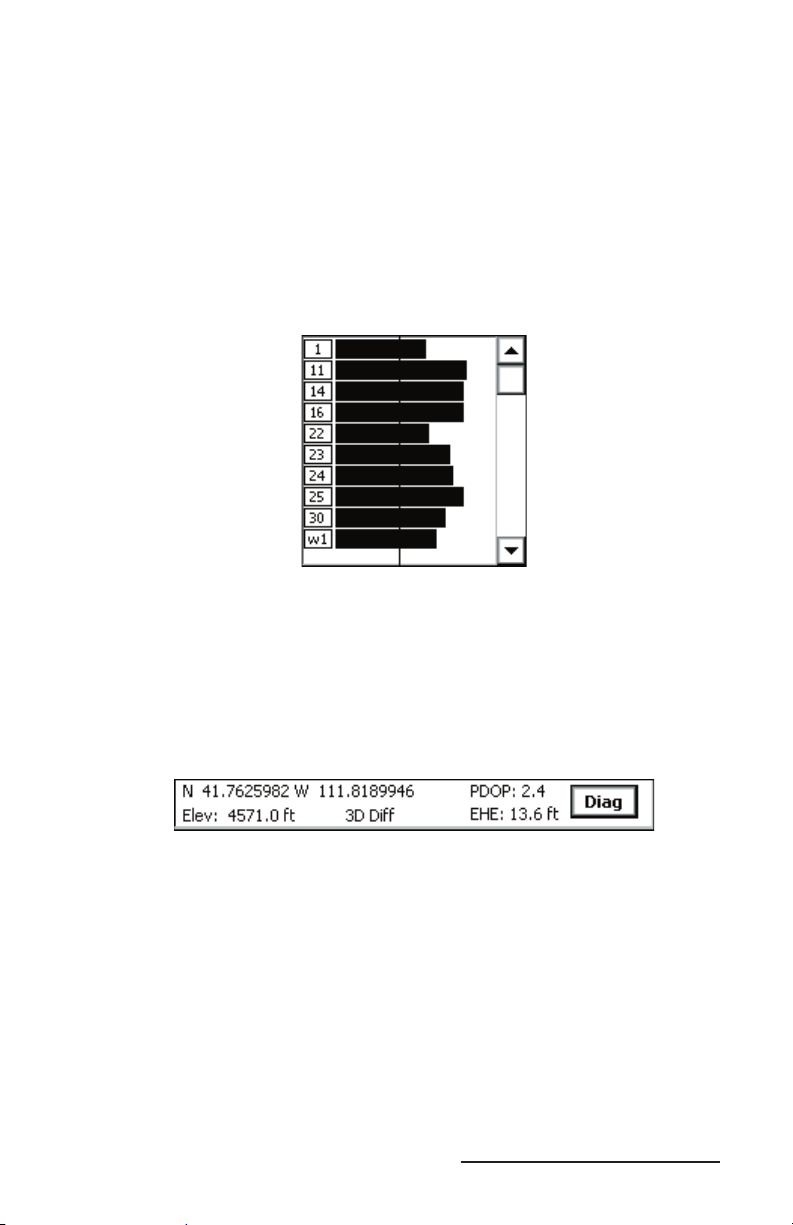
The right side of the screen displays a bar graph showing the relative
satellite signal strengths. Each satellite is assigned an SV number
(space vehicle or satellite vehicle number). These numbers appear to
the left of their corresponding signal strength bars. A boxed number
indicates which particular satellite is being used to determine the
GPS position.
Note: Only active satellites are displayed on the bar graph, but all
viewable satelites are displayed in the Skyplot. The scroll bar on the right of
the graph box allows you to view all displayed satelites.
Latitude, longitude, elevation, and satellite quality values are shown
below the skyplot section of the GPS screen. The PDOP (Percent
Dilution of Position) and EHE (Estimated Horizontal position Error)
values are shown under the bar graphs.
PDOP
▲
PDOP (Percent Dilution of Position) is based on the geometric
arrangement of satellites, and indicates the quality of GPS readings.
Optimal PDOP occurs when one satellite is directly overhead and
three others are evenly spaced out over the horizon. A PDOP less
than 4 gives the best accuracy, between 4 and 8 is acceptable, and
greater than 8 is poor.
EHE
▲
EHE (Estimated Horizontal Error) indicates the amount of receiver
horizontal position uncertainty. This reading is an estimate based
on PDOP, HDOP, and other parameters from the GPS receiver. The
smaller the number the closer the estimate.
LandMark CE User’s Manual 25
Page 26

Note: The EHE reading appears in either feet or meters depending on
the measurement preferences that are set in the Confi guration screen.
Elev
▲
Elev (elevation) is the altitude where you are geographically
positioned. For display options, go to the Altitude Reference section
later in this chapter.
GPS Status Quality — Receiving Data
▲
GPS status quality is shown to the right of Elev reading and consists
of the following mode indicators when receiving any data:
Mode Meaning
3D Diff Fix from 4 or more satellites; receiving real-time
corrections from WAAS, beacon, etc.
2D Diff Fix from 3 satellites; receiving real-time corrections from
WAAS, beacon, etc.
3D GPS fi x from 4 or more satellites; including elevation.
2D GPS fi x from 3 satellites; no elevation.
3D PPS Precise Positioning Service; need capability to read PPS
code; Excellent signal.
2D PPS Precise Positioning Service; need capability to read PPS
code; Excellent signal.
3D RTK Real-Time Kinematic; measure lat/long/height above
WGS-84 datum to within a few centimeters.
2D RTK Real-Time Kinematic; measure lat/long/height above
WGS-84 datum to within a few centimeters.
Note: Depending on the quality of receiver and the receiver capabilities,
different messages are displayed.
Using 3D Diff or 2D Diff Mode
The 3D Diff or 2D Diff mode is only displayed when the receiver is
receiving real-time differential corrections from WAAS, beacon, base
station, Omnistar, etc.
Using 3D or 2D Mode
The 3D or 2D mode is the standard for most receivers.
Using 3D PPS or 2D PPS Mode
The 3D PPS or 2D PPS mode is only displayed when the receiver
being used is capable of reading PPS code from three or more
satellites.
26 LandMark CE User’s Manual
Page 27

Using 3D RTK or 2D RTK Mode
The 3D RTK or 2D RTK mode is only displayed when the receiver
being used is capable of reading RTK code from three or more
satellites.
GPS Status Quality — Not Receiving Data
▲
GPS status quality is shown to the right of Elev reading and consists
of the following indicators when not receiving any data:
No Com Actv.
No New Data
COM Discnt
COM Errors
No Fix
No Com Actv.
No Com Actv. (activity) indicates that the GPS receiver is not sending
data, or the communication wire has been disconnected from
the COM port. Check to be sure that the GPS is connected to the
specifi ed COM port and that it is attached properly.
No New Data
No New Data indicates that the COM has been set up right, and the
GPS is sending data properly, but the data is not in a readable format
(i.e. data not in NMEA format).
COM Discnt
COM Discnt (disconnect) indicates that the program tried to open the
specifi ed COM in Confi gurations, but it could not open it. Check the
confi gurations for the right COM port, or do a soft reset.
COM Errors
COM Errors indicates that the baud rate is not set correctly, or the
COM port could be set wrong. Check the confi gurations and select
the correct baud rate specifi ed by your GPS receiver, and make sure
you are connected to the correct COM port.
No Fix
No Fix indicates that the GPS is not sending quality data. Empty
strings of NMEA are being received, so a GPS fi x cannot be
calculated. Wait for data to be received, or move to a new location.
LandMark CE User’s Manual 27
Page 28

Diagnostics
▲
Tap on the Diag (Diagnostics) button within the GPS Status screen.
The GPS Diagnostics screen displays a dialog box showing your
position and packet information, or NMEA data strings, supplied
from GPS receiver. These NMEA data strings are displayed in their
entirety and can be viewed by using the scroll bar at the bottom of
the screen.
Displayed on the right side of the dialog box are the following
diagnostics and information headings:
sv/used
Quality
2D/3D
W1/W2
Below each heading is a number(s) displaying specifi c data recieved.
Sv/used
The sv/used heading means Satellites in view/ number being used
in fi x. The numbers 12/5 are displayed in the example above.
12 = number of satelites in view
5 = number of satelited being used to establish GPS fi x
Quality
The Quality heading shows the quality of your GPS fi x.
0 = no fi x
1 = GPS
2 = Differential
3 = PPS (Precise Positioning Service)
28 LandMark CE User’s Manual
Page 29

4 = RTK (Real-Time Kinematic)
5 = RTK (Real-Time Kinematic)
2D/3D
The 2D/3D heading shows the current number of satilite fi xes.
1 = no fi x
2 = 2D fi x (minimum of 3 satelites)
3 = 3D fi x (minimun of 4 satelites)
W1/W2
The W1/W2 heading shows WAAS satelites.
0 = no WAAS
1 = WAAS satellites visible but not used
2 = WAAS satellites used
3 = Visible and used
Note: WAAS enabled receivers receive WAAS corrections, but not
additional satellite information.
Satellite Details
The Satellite Details button within the GPS Diagnostics screen opens
the satellite details screen. Tapping on this screen button displays
a dialog box showing the SV number, azimuth, elevation, signal to
noise ratio, and use status of all GPS satellites in view. When WAAS
satellites are visable, they are shown on Satellite Details screen.
Note: The WAAS satellite information may or may not be shown due
to manufacturer’s specifi cations. Not all receivers pass WAAS satellite
information in the NMEA strings.
Satellite Details Screen
LandMark CE User’s Manual 29
Page 30

Sat #
Sat #, or SV number, indicates the satellite vehicle, or space vehicle
number.
Azimuth
Azimuth is the bearing measurement in degrees from North that
represents the horizontal direction of the satellite from the current
position.
Elevation
Elevation is shown in degrees and is the angular measurement
above the Azimuth line, which gives the satellite’s height above
the horizon. A satellite located lower on the horizon has a lower
elevation in degrees.
SNR
SNR is the Signal to Noise Ratio, or the ratio of signal received to
noise received. More signal, or higher number, indicates a stronger
signal strength. More noise indicates less signal strength.
Used
Used is the status of the satellite’s signal in calculating the current
location. If the satellite signal is picked up by the receiver, but the
signal is not strong enough, or if the satellite is not benefi cial to
use due to poor geometric arrangement, it is not used for position
calculation. Ye s indicates that the satellite’s data is being used to
calculate your position. No indicates that the satellite’s data is not
being used to calculate your position.
Freeze/Unfreeze
The button title automatically toggles between Freeze and Unfreeze
depending on your selection. The button title displays the action
that occurs when the button is tapped. The Freeze button captures the
Packet Info (data stream) instantaneously from the GPS receiver. Tap
Unfreeze to return to the continuous data stream mode.
30 LandMark CE User’s Manual
Page 31

Nav Screen
The Nav screen allows users to collect point information, calculate
point differences, check survey lines, and specify a path of travel. To
display the Nav Screen, complete one of the following steps:
Tap on the Nav option at the top of the menu bar.
Tap on Go to access a drop-down menu and select Nav.
Press F2 on the Allegro keyboard.
The Navigation screen is shown below:
The Navigation screen displays the following features, discussed
later in this section:
From
To
Compass
Here -> TO
FROM -> TO
Quality
Mag Dec
From
▲
The From box displays the waypoint that is the starting point you
intend to begin traveling from. The option Here is the current
position.
LandMark CE User’s Manual 31
Page 32

To
▲
The To box displays the waypoint that is the ending point. This point
is where you intend to stop at once you arrive there.
Waypoint File
Waypoint fi les are fi les consisting of points that have been saved and
labeled. Before the navigation function can be used, a waypoint fi le
must be identifi ed and opened.
When waypoints within the fi le are selected in the From and To
boxes, the Nav screen fi elds update the following:
Compass
Here -> To
From -> To
Quality - Always updated - Current GPS status
Mag Dec - Set value based on Confi guration Settings
Note: If the GPS receiver is not active, only the From -> To box is
updated.
LandMark CE allows having multiple fi les and does not limit how
many waypoint fi les are used. You can log 256 waypoints in each
waypoint fi le.
To open a waypoint fi le, complete one of the following steps:
Tap on File/New to create a new waypoint fi le.
1)
Tap on File/Open to open an existing fi le.
2)
A waypoint fi le is now activated.
Compass
▲
The compass is shown on the left side of the screen. The compass
rotates to show the direction of travel when you start moving. It is
updated when your speed is greater than 0.5 km/hr (0.31 mph).
The arrow is fi xed and always points toward the To location and
assumes the direction of travel is the top of the screen. The compass
body rotates to show the current direction of travel, as long as you
are moving. When you stop, the top of the compass points to the
north.
Here -> To
▲
The Here -> To section of the Navigation screen, shown on the upper
right, displays calculated values based on the current GPS location
(Here) and the destination (To) location.
32 LandMark CE User’s Manual
Page 33

Distance
The Distance box displays the distance in the selected current units
(meters or feet) from the Here to the To location.
Bearing
The Bearing box displays the compass heading in degrees from Here
to the To location.
Track
The Track box displays the direction you are traveling in degrees.
Speed
The Speed box displays the speed you are moving in current display
units (km/h or mph).
XTE
The XTE box gives the shortest distance between the current
location of the GPS receiver and the line that connects the From
and To locations. A positive (+) XTE is to the right of the path and a
negative (-) XTE is to the left, meaning you are traveling toward the
To location.
From -> To
▲
The From -> To section of the Navigation screen displays calculated
values based on the From location to the To location. When changing
From or To waypoints, displayed information in the Here -> To section
may not be updated until you start moving; this can depend on the
GPS receiver being used.
The From -> To section is updated even without receiving GPS signal.
Once the From and To waypoints are selected, the values in the From
-> To section do not change.
Distance
The Distance box displays the distance in current units (metric or
standard) from the From location to the To location. The distance
converts to miles or km when the distance reads high enough that it
applies.
Azimuth
The Azimuth box displays the compass heading in degrees from the
From location to the To location.
Quality
▲
See GPS quality status explanations located earlier in this section.
LandMark CE User’s Manual 33
Page 34

Heading Setting
▲
The heading setting is located below the Quality status line. It
displays which heading the compass is set to. Options include True
North, Auto Magnetic, Manual Magnetic, or the World Magnetic
Model Epoch 2000 (WMM-2000 or WMM 2K).
For more information about the heading settings and the options
available to you, go to the Heading title in the Confi guration Screen
section of this chapter.
34 LandMark CE User’s Manual
Page 35

Confi guration Screen
The Confi guration screen allows you to customize LandMark CE
according to operational preferences.
To display the Confi guration screen, complete one of the following steps:
Tap on the Cnf option at the top of the menu bar.
Tap on Go to access a drop-down menu and select Confi g.
Press F3 on the Allegro keyboard.
Note: You must fi rst exit the Confi guration screen to be able to use the
F1-F4 keys again.
The Confi guration screen contains seven tabs, GPS, File, Data, Units,
Mask, HotKeys, and Keybd. This section covers the options available
in each one of these tabs.
To use the Confi guration screen via the keyboard, use the tab keys
(forward or back tab), space bar, and the arrows key. To exit the
Confi guration screen, you can either press Enter on the keyboard,
or you can tap OK in the top right hand corner of the screen, to
automatically save all your confi guration changes.
Note: Pressing the ESC key or tapping on the X in the top right hand
corner does not save any of the confi guration changes you have made.
LandMark CE User’s Manual 35
Page 36

GPS Tab
▲
The GPS tab is used to confi gure the COM port you are using to
attach the GPS receiver. Any changes to the communication port
become effective immediately, a program restart is not needed.
Port
The Port fi eld allows you to select the communication port you are
using. LandMark CE currently supports communication ports COM1
through COM9.
Note: If you are using the Holux receiver, you need to use COM1 and
check the DTR option.
To set the correct port for GPS communication, complete the
following steps:
Using a stylus: Tap the down arrow next to the Port box to access
1)
the drop-down menu and tap on the desired COM Port.
Using the keyboard: Push the Ta b key to highlight the Port box.
When the box is highlighted, use the arrows key to move through
the available COM Port options.
Close the Confi guration screen by tapping on OK in the top right
2)
corner of the screen, or by pressing the Enter key.
36 LandMark CE User’s Manual
Page 37

Bluetooth COM Ports
LandMark CE has multiple automated functions specifi cally for
Bluetooth receivers.
Bluetooth COM Port Usage Auto Detection
When a user selects a Bluetooth COM port or when the application
loads, LandMark CE automatically detects when a Bluetooth COM
Port is being used. If a Bluetooth receiver is set as a favorite when
more than one device is available, loading the COM port defaults
to the desired receiver and bypasses the Bluetooth device selection
screen.
Auto Reconnect
When a Bluetooth connection is lost, LandMark CE automatically
tries to reconnect up to three times.
Auto Bluetooth Card Power Shut-off
When using Bluetooth PC cards, the power to the card is shut off
when the Allegro is suspended. LandMark CE registers with the
Bluetooth stack to the GPS receiver status, when the stack is loaded
or unloaded. This reduces the reload time when coming out of
suspend and auto connects the receiver when the stack is reloaded.
Note: If Bluetooth is not active when the Allegro is suspended,
LandMark CE does not auto connect.
Baud
Baud determines the signaling speed. The rate at which the COM
port accepts data must match the rate that the GPS receiver sends
data. If the Baud is not set correctly you will get the following
message:
LandMark CE User’s Manual 37
Page 38

If using a GPSPOD with a Trimble Lassen LP receiver, complete the
following steps, otherwise skip to step 6 and proceed:
Note: Steps 1 - 5 only apply when using the built in GPS pod for the
Allegro through COM 3. The Holux 211 receiver is completely external,
or any Bluetooth, and only the settings in the Confi g screen need to be
properly set.
Exit out of LandMark CE.
1)
Tap on the Start button and navigate through Programs | Utilities
2)
| GPS Pod Setup.
Tap on the Get Settings button when the GPS Receiver Port Settings
3)
screen appears and wait for the readings to appear.
Note: Make sure you select GGA, GSA, VTG, and GSV as the
minimum number of NMEA packets to use with LandMark CE.
Confi rm you are using the NMEA setting in the GPS Data Format
4)
section and write down the baud rate.
Tap on the Apply Settings button if you made any changes and
5)
tap on the X in the top right corner to exit the GPS Receiver Port
Settings screen.
Note: If new settings are not shown after they are applied, repeat the
process until changes are shown as updated.
Go to the GPS tab of the Confi guration screen and enter the correct
6)
Baud.
Note: If the Com Port Error message appears, tap in the box next to the
Don’t display this message again during this session message so a check
mark appears and tap on the OK button before checking your Allegro for the
set baud rate.
38 LandMark CE User’s Manual
Page 39

Parity, Data Bits, Stop Bits
As with Baud rate, the communication parameters for Parity, Data
Bits, and Stop Bits must have those of the receiver. Parity, Data Bits,
and Stop Bits are specifi ed by the GPS receiver’s manual. Please see
the user’s manual for these values and set them accurately.
DTR
The DTR (Data Terminal Ready) option uses a 5V power supply that
is only used with COM1 and when a external GPS receiver is being
used which needs a power supply.
RTS
The RTS (Ready to Send) option is a standard when using serial port
communication. You should only select this option when requested
by the GPS receiver.
File Tab
▲
The File tab defi nes where you want to store your LandMark CE
waypoint fi les on the Field Computer.
Waypoint Data Path
LandMark CE automatically defaults to \C_Drive\C_MyDocs\ for
Waypoint Data Path. Tap on Browse to set a different location for the
waypoint fi le. This feature makes saved waypoint fi les easy to access.
Data Exchange
Data Exchange gives you the option of easily maneuvering GPS data
between two applications. Every time a new point is created using
the Mark Point screen (explained in detail later in this chapter), a fi le
named dtex.txt is overwritten or created in the location you have
specifi ed in the File tab.
LandMark CE User’s Manual 39
Page 40

When the Export button is tapped in the Mark Point screen, your
last active application opens automatically. Press Enter or type a
command to read the modifi ed dtex.txt fi le and obtain the GPS data.
(See the Mark Key section later in this chapter for further details on
Mark Point screen.)
Ini File Write Protected
The Ini File Write Protected box indicates whether a general fi eld user
can change confi guration settings when checked. This option ensures
that all data being collected are always the same format, regardless
of which user is operating LandMark CE. To check the box and lock
the confi gured settings, see the Programmer’s chapter.
Data Tab
▲
Once the data are calculated in the specifi ed format, Data tab options
determine how they are sent to their fi nal locations, through Data
Exchange, Memory Exchange, or Keyboard Wedge.
Mark Point Options
Point Averaging, Number of Points, and Data Exchange File all apply to
the Mark Point screen. The Mark Point screen pops up when the Mark
Hot Key is pressed. (See HotKeys tab to set up the Mark Hot Key.)
Point Averaging
Checking Point Averaging activates the point averaging function; if
this option is left unchecked, no averaging occurs when marking a
waypoint. Typically new GPS points are received once per second
from the GPS receiver. The GPS receiver calculates a new average
about once per second.
40 LandMark CE User’s Manual
Page 41

Each new position is included in the running average until the
specifi ed number of positions to calculate the overall average have
been accumulated. Point Averaging is used when the Mark Point
screen is open.
Note: Masked position information is not included in the average. See
the Mask Tab section in this chapter for more information.
Number of Points
Enter in a Number of Points after you have checked the Point
Averaging box. This user-specifi ed number of GPS positions is used
when calculating averaged waypoints.
Data Exchange File
Check the Data Exchange File option to use the data exchange path
when exporting an averaged point. See the Data Exchange section in
this chapter.
Export button saves to waypt fi le
Check Export button saves to waypt fi le to both save data as a
waypoint, and to export data concurrently when the Export button is
tapped.
Memory Exchange
Check the Memory Exchange option to share location data with
another application. See the Programmer’s chapter for more
information.
Keyboard Wedge
Check the Keyboard Wedge option to activate the wedge Hot Key.
Keyboard Wedge allows the latitude, longitude, and elevation to be
sent directly into another application when the Hot Key is pressed.
This is useful when you want a simple GPS point logged in another
application.
LandMark CE User’s Manual 41
Page 42

Units Tab
▲
The Units tab is used to format data. For example, say that your data
needs to be calculated in feet, with magnetic declination set, in UTM
scale, and mean sea level altitude reference set. Set up all of these
confi gurations in the Units tab. Selected settings are also used in
displayed data for Keyboard Wedge and Memory Exchange.
Datum
The Datum option is a set of constants used for calculating
coordinates on earth. Datum points are used by the GPS to reference
a point or line in measuring elevation. LandMark CE automatically
defaults to WGS-84, the datum constants established by the World
Geodetic System in 1984 (WGS 84).
A selection of over 200 different map datum points from around
the world can be used to convert the position to a different datum.
When waypoints are stored, they are always recorded in the WGS 84
datum.
42 LandMark CE User’s Manual
Page 43

Units
The Units option allows you to specify the units of measurement that
you want your data to be expressed in. Choices include feet, miles,
meters, kilometers, knots, miles per hour, or kilometers per hour.
Display Option Distance Units Speed Units
Statute Feet, Miles Miles per hour (mph)
Metric Meters, Kilometers Kilometers per hour
Nautical Feet, Nautical Miles Knots
Feet Feet (changes to miles
at 13,000 ft.)
Meters Meters (changes to kilo-
meters at 1500 m)
Miles per hour
Kilometers per hour
Heading
The Heading option allows you to set the display compass readings
to the following:
True
Auto Mag (automatic magnetic declination)
Manual Mag (manual magnetic declination)
WMM 2K (World Magnetic Model 2000)
Declination is the angle formed between magnetic north and true
north from the GPS receivers location.
Tr ue
The True selection uses true North as the compass heading.
Auto Mag
The Auto Mag selection displays all compass headings as magnetic
north using the magnetic declination value from the NMEA RMC
packet sent by the GPS satellite. The declination is applied to
the Auto Mag reading and appears on the GPS screen modifi ed,
adjusting for the altered declination degrees.
Note: If the receiver you are using is not able to use RMC or VTG
NMEA packets and the declination does not appear in the Diagnostic
screen, do not use Auto Mag with that receiver.
LandMark CE User’s Manual 43
Page 44

Manual Mag
The Manual Mag value uses a negative (-) number for East
declination and a positive (+) number for West declination. When
manually entering the declination, use the box to the right of the
Heading drop-down menu and specify either East (using a negative
value) or West (using a positive value).
WMM 2K
Earth’s magnetic fi eld, as measured by a magnetic sensor on or
above the Earth’s surface, is a composite of several magnetic fi elds
generated by a variety of sources.
The World Magnetic Model Epoch 2000 (WMM-2000 or WMM 2K) is
a generated model used to confi gure and display magnetic north on
GPS units. The World Magnetic Model coeffi cients are produced and
distributed by the National Geospatial Intelligence Agency (formerly
National Imagery Mapping Agency), Washington, D.C.
The model, associated software, and documentation are distributed
by NGDC on behalf of NGA. The model is produced at 5-year
intervals. The 2005 - 2010 model will be available from NGDC on the
following website on 12/2004:
http://www.ngdc.noaa.gov/seg/WMM/DoDWMM.shtml
Follow the direction on the above website to download the necessary
fi le. Once the fi le is downloaded, place the fi le in the LandMark CE
folder on your Allegro.
Note: Some GPS receivers may not supply the magnetic declination.
If your GPS receiver uses the Sirf chipset, it probably does not provide the
magnetic declination value.
Format
The Format option allows you to select the format for displaying
your location. Latitude/ longitude can be set to degrees, degrees
and minutes, or degrees, minutes, and seconds; UTM can be set to a
northing/easting format.
Format What is Displayed
ddd.ddddddd latitude/longitude in decimal degrees
ddd mm.mmmm latitude/longitude in degrees and decimal
minutes
ddd mm mss.ss latitude/longitude in degrees, minutes and
seconds
UTM northings/eastings
44 LandMark CE User’s Manual
Page 45

Altitude Reference
The Altitude Reference option displays the altitude as MSL (mean
sea level) or HAE (height above ellipsoid). When MSL is selected,
its value is calculated when the GPS receiver provides the geoidal
separation value in the NMEA GGA packets from the satellite.
Mask Tab
▲
The Mask tab is used to set the GPS signal masking parameters while
marking waypoints. Only those GPS fi xes that meet the specifi ed
criteria are used in averaging a waypoint. In essence, inaccurate GPS
positions are screened with this feature.
The check boxes are used to enable or disable specifi c masking
features. The edit boxes on the right of the check boxes are used to
specify the mask value.
Max PDOP
Select the Max PDOP (Maximum Percent Dilution of Precision)
option and then enter a value in the box to the right. This selection
masks GPS PDOP readings greater than the value entered. Only
computed waypoints with a PDOP equal to or less than the value
you entered are used.
Max EHE
Select the Max EHE (Maximum Estimated Horizontal Error) option
and then enter a value in the box to the right. This masks GPS EHE
readings greater than what you enter. Only computed waypoints
with an EHE equal to or less than the value entered are used.
LandMark CE User’s Manual 45
Page 46

DGPS Only
Select the DGPS Only option to collect GPS fi xes with differential
corrections. When selected, all other points that are not DGPS are
masked.
3D Only
Select 3D Only to collect waypoints that are received when using at
least four satellites.
Min Sat Elevation
Select Min Sat Elevation (Minimum Satellite Elevation) and specify
the minimum elevation in the box to the left. Satellites that are equal
to or greater than the elevation value entered are included in the
waypoint averaging.
Min Sat SNR
Select Min Sat SNR (Minimum Satellite Signal to Noise Ratio). A
higher SNR is a better reading. A SNR value less than 4 is considered
unusable. SNR values above the specifi ed value are valid.
HotKeys Tab
▲
Use the HotKeys tab to set up user specifi ed keys that automatically
save a waypoint or send GPS data to a different application when
pressed.
46 LandMark CE User’s Manual
Page 47

The following are the three keys that can be used for the Wedge Key
or Mark Key:
Task manager
Insert
Delete
Mark Key
Select a Mark Key from the drop-down menu. Whenever that key is
pressed it brings up the Mark Point screen.
Wedge Key
Select a Wedge Key from the drop-down menu. Whenever that key
is pressed, it sends the GPS position into another active application.
See Keybd to specify the order you would like the data to appear.
Keybd Tab
▲
The Keyboard (Keybd) tab is used to specify how you want data
entered into another application when the Wedge Key is pressed.
You can specify the order that latitude, longitude and elevation are
recorded. You can also set up carriage returns and tabs for the data
sent. The Keybd specifi cations work for any other applications being
used.
Note: As an example, PTab is the application used to explain the Keybd
functions.
LandMark CE User’s Manual 47
Page 48

Available Data Items
Available Data Items are listed options for how and what data are
transferred. Select data items by highlighting and then tapping the
arrow button between the Available Data Items box and the Selected
Data Items box. Available Data Items are then copied into the Selected
Data Items box. Asterisks denote data that can be transferred, while
items without asterisks specify data formatting options.
Selected Data Items
Selected Data Items are items that have been selected from the
Available Data Items list. The order of the items is signifi cant to how
the data are displayed in the concurrent program when the Wedge
Key is pressed.
Items Left
The Items Left starts out with the number 35, indicating how many
total Selected Data Items options are available. As you select items,
this number is reduced by one for each selection.
For example, if you select latitude, tab, longitude, tab, elevation,
down arrow, and then left arrow 3 times, you have used 9 of the 35
options, and the Items Left number reads 26 after this example.
U
The U (up) button moves a Selected Data Item entry up, switching
places with the item above it.
D
The D (down) button moves a Selected Data Item down, switching
places with the item below it.
Del
The Del (delete) button deletes the item highlighted in the Selected
Data Item box.
Internal
Select one of the Internal options to split your whole data string into
smaller segments. One data string includes what you have specifi ed
in the Selected Data Items box display. When your data string is being
sent to the concurrent program, it is entered and separated into
different cells or fi elds according to the option you have selected.
48 LandMark CE User’s Manual
Page 49

For example, when Tab is selected in Internal and ddd mm ss.ss is
selected in Units/Format, a latitude data string in PTab is entered as
follows: N has its own cell, ddd has its own cell, mm has its own cell,
and ss.ss would have its own cell. This feature is nice for applications
that require data calculations.
Note: If you have an Internal option selected, be sure that your Selected
Data Items box is fi lled in correctly.
The Internal options are accessed from a drop-down list with the
follow settings and data format after each data segment:
Internal
Setting Data format after each data segment
Tab The cursor automatically tabs over to the next fi eld.
Right The cursor automatically moves to the right one space.
Left The cursor automatically moves to the left one space.
Up The cursor automatically moves up one line.
Down The cursor automatically moves down one line.
Return The cursor automatically returns.
Space The cursor automatically inserts a space.
Display Data are entered exactly as displayed on the GPS
screen in LandMark CE.
N/A N/A automatically comes up when the Raw Data box
is checked. No formatting of data segments occur and
only number values are transmitted.
Raw Data
Click the Raw Data box for non-confi gured data entered into a
concurrently running program when the wedge HotKey is pressed.
LandMark CE User’s Manual 49
Page 50

Waypoint Screen
Use the Waypoint screen to display and manage the contents of the
currently selected waypoint fi le. The available functions allow for
marking points, editing points, and deleting points from a waypoint
fi le.
To display the Waypoint screen, complete one of the following steps:
Tap on the Wpt option at the top of the menu bar.
Tap on Go to access a drop-down menu and select Way Pts.
Press F4 on the Allegro keyboard.
Before working in the waypoint screen, you need to create or open a
waypoint fi le. Do this by using the File menu.
The waypoints in the open waypoint fi le are displayed in a list on the
left side of the display. Selecting a waypoint displays its waypoint
number, ID or name, latitude, longitude, elevation, PDOP, and EHE
on the right side of the screen.
New
▲
Tap New to create a new waypoint and manually enter its
coordinates. This feature allows you to enter points without actually
going into the fi eld.
50 LandMark CE User’s Manual
Page 51

When New is tapped, a pop-up screen appears.
Change the Waypoint ID and fi ll in latitude, longitude, and
elevation. The units format depends on what is selected in the
confi gurations screen. (See Confi guration instruction to change Units
format.)
Waypoint #
Waypoint # is the number assigned by LandMark CE. All points in a
waypoint fi le are numbered consecutively.
Waypoint ID
Waypoint ID is the point name that you give to a point.
Latitude
Latitude shows a waypoint latitude.
Longitude
Longitude shows a waypoint longitude.
Elevation
Elevation shows a waypoint elevation.
When you are fi nished entering all fi elds, tap on the OK button to go
back to the Waypoint screen. All of your point information is saved
into the waypoint fi le when you tap on OK.
Edit
▲
Tap Edit to edit the selected waypoint. When Edit is selected,
the Waypoint pop-up screen is displayed. The exact format of
the waypoint screen depends on the Units format selected. (See
Confi gurations instructions to change Units format.)
LandMark CE User’s Manual 51
Page 52

Note: A recommended practice is not to edit a waypoint very many
times when using a datum other than WGS-84. The conversion between
datums that occurs internally can potentially introduce errors into the
original GPS data.
Del (Delete)
▲
Tap Del to delete the selected waypoint. When the pop-up box
appears, select yes to delete, or select no to return to the Waypoint
screen.
Mark
▲
Tap on the Mark button to capture a current location waypoint using
the Mark Point pop-up screen. (The Mark Hotkey also activates this
feature. For more information see the Hotkey section of this chapter.)
The Mark Point screen automatically assigns a waypoint number and
a MarkID number. The MarkID number can be changed to any text
value by selecting that fi eld and entering the desired name using the
keyboard. The MarkID number is what shows up on the left-hand
side of the Waypoint screen.
Note: The Average button only appears if the Point Averaging option is
selected on the Data tab of the Confi guration screen.
Current GPS
The top of the screen shows Current GPS readings. Each new GPS fi x
from the GPS receiver updates the location, elevation, quality, PDOP,
and EHE values while the Mark Point screen is active.
Waypoint #
The Waypoint 1 (the number varies depending on the waypoint fi le
being used) box displays the Waypoint fi le you are currently using.
52 LandMark CE User’s Manual
Page 53

Offset
Tapping on the Offset button opens a Offset Input screen. This screen
enables the user to specify the distance, direction, and slope from the
initial (current) location to an offset location.
Distance
The Distance box sets the direct distance in displayed units to the
offset point.
Direction
The Direction box sets the angle, in degrees, measured from North
to the offset point. Next to the Direction box is the Ref (reference)
label. This displays the heading you set up in the confi guration of
LandMark CE and the declination angle. The reference used for each
point is stored with the waypoint.
Slope
The Slope box sets the angle, in degrees, of altitude inclination. A
negative number represents a declination in altitude.
This ability to offset points is valuable in many situations. For
example: The offset function can be used when a point you want to
mark is inaccessible (i.e. like a power pole behind a fence or an island
in a lake), when the GPS signal at a desired point is unavailable (it
may be blocked), or when gathering points from a vehicle without
having to get out of the vehicle.
To use the Mark Point Offset function, complete the following steps:
Fill in the Distance from where your current location is to the
1)
point you are wanting to save.
Fill in the Direction in degrees that the new point is located.
2)
Fill in the Slope from where you are located to the new point. This
3)
is a useful tool to determine the a clinometer.
LandMark CE User’s Manual 53
Page 54

4)
Check the Offset On check box, after these fi elds are fi lled in,
if you want the offset calculations activated before closing the
waypoint.
Now, whenever you select the saved offset point, if the Offset On
check box is checked, an indicator appears in the Waypoint screen
while viewing the point information.
If you want to view the unaltered point information, tap on the Edit
button in the Waypoint screen.
Offset values are activated automatically when saving/closing the
waypoint by tapping on the OK button. The Cancel button does not
save any of settings or impose the new offsets.
Average
The Average button is used to average GPS fi xes that pass the mask
settings. When you press the Average button, the bar graph above
starts to fi ll, showing a ratio of points that have been included in the
average so far.
The status/quality of GPS averaging is displayed in the box to the
left. If a reading is masked, the reason for being excluded from the
average is displayed in the box to the left.
The running and fi nal averaged information is located to the left of
the Average button. While a waypoint is being averaged, the average
button displays Averaging.
If the Store Wpt button is pressed during the averaging process, the
fi nal average is not stored until all the points specifi ed to compute
the average have been included. (Notice how the Store Wpt button
shows waiting while still averaging). Similarly, fi nal data cannot be
exported until averaging is complete.
Store WPT
The Store WPT (Store Waypoint) button is used to store an average
waypoint in the current waypoint fi le. If the Store WPT button is
pressed before the Average button (if the button is available), the
averaging process begins automatically and continues until all points
for the average have been obtained. After the point is averaged it is
stored in the waypoint fi le.
In both cases, after the averaged waypoint is stored, the Mark
Point screen will close. The new waypoint is included in the list of
waypoints on the left side of the Waypoint screen.
54 LandMark CE User’s Manual
Page 55

Export
The Export button starts the average function, and then exports the
averaged point to your Waypoint Data Path (See Confi guration/File to
set up Waypoint Data Path).
Note: When the waypoints fi le reaches the 256 point limit, the Export
button can still be used to export data to another application, but a new
waypoint fi le must be created if additional points must be stored.
Cancel
Tapping the Cancel button closes the Mark Point screen.
LandMark CE User’s Manual 55
Page 56

56 LandMark CE User’s Manual
Page 57

Chapter 4
Troubleshooting
Error Messages and Warnings
LandMark CE User’s Manual 57
Page 58

Error and Warning Messages
LandMark CE displays pop-up messages when an error occurs.
The following section lists the possible error messages and suggests
how to fi x the problems related to an error message.
LandMark CE Startup Error Messages
▲
The following are the error messages and suggested fi x for those
messages that may occur during LandMark CE startup.
Error message:
Application Path Not Found. Please make sure the path
‘C_Drive\C_Program Files\LandMarkCE’ exists. If it does
not, please re-install LandMark CE.
This error message appears for one of the following reasons:
The path, C_Drive\C_Program Files\LandMarkCE, (the
1)
LandmarkCE default installation path), was changed after
installation.
You tried to copy the Landmark CE folder from another Allegro.
2)
You must use the installation CD to set the path where the
LandMark CE is installed on the Allegro.
A factory default reset on the Allegro was performed; LandMark
3)
CE is still saved in the C_Drive, but the registry has been erased.
To fi x the error, reinstall LandMark CE.
Error message:
Error initializing datums. If “3_param.dat” and “7_param.
dat” fi les are corrupt, re-install, or check for correct
application path (\C_Drive\C_Program Files\LandMarkCE).
When LandMark CE is installed, datum fi les are saved in the registry
as 3_Param.dat, and ellipse.dat. This error message appears for one of
the following reasons:
The registry is corrupt, or a Set Factory Default was executed.
1)
The program path was modifi ed, so the registry path is no longer
2)
available.
The 3_Param.dat, and ellipse.dat fi les were deleted.
3)
Fix the error by either checking the registry path, or reinstalling
LandMark CE.
58 LandMark CE User’s Manual
Page 59

Error message:
Could not fi nd Ellipse.dat fi le.
Ellipse.dat fi les are datum fi les saved in the registry. This error
message appears for one of the following reasons:
The registry is corrupt, or a Set Factory Default was executed.
1)
The program path was modifi ed, so the registry path is no longer
2)
available.
The ellipse.dat fi les were deleted.
3)
To solve the problem, check the registry path. Registry errors can be
fi xed by doing a soft reset. If the soft reset does not work, reinstall
LandMark CE.
Error message:
Error Initializing WMM2K - WMM.COF File not found.
WMM is a formula used to calculate magnetic declination from GPS
data. Most receivers do this calculation, but some do not. In the
instance that a receiver does not calculate magnetic declination, you
need to use either Manual Mode, or WMM 2K for calculations.
The error message appears if the WMM.COF fi le cannot be found.
The following are reasons for not being able to fi nd the fi le:
The registry is corrupt, or a Set Factory Default was executed.
1)
The program path was modifi ed, so the registry path is no longer
2)
available.
The WMM.COF fi le was deleted.
3)
The date setting on the Allegro precedes the year 2000.
4)
Registry errors can be fi xed by doing a soft reset. If the soft reset does
not work, reinstall LandMark CE.
Error message:
lm.ini File not found - Default values used.
The lm.ini fi le is where LandMark CE’s specifi cations are written.
This message appears for one of the following reasons:
The registry is corrupt, or a Set Factory Default was executed.
1)
The program path was modifi ed, so the registry path is no longer
2)
available.
The lm.ini fi le was deleted.
3)
Registry errors can be fi xed by doing a soft reset. If the soft reset does
not work, reinstall LandMark CE.
LandMark CE User’s Manual 59
Page 60

Error message:
Datum not defi ned. Using WGS84 (Default Datum).
This message appears for the following reason:
A programmer changed the datum in the lm.ini fi le. The
1)
new datum value was not valid and is therefore unusable by
LandMark CE. LandMark CE automatically defaults to WGS84
when this happens.
Fix the error by changing the lm.ini fi le datum. See Programmers
chapter for more information.
Error message:
Cannot open LandMark CE registry key.
The registry is a database maintained by the operating system. This
error messages appears for one of the following reasons:
Another program has opened the LandMark CE registry.
1)
LandMark CE did not close the registry properly the last time it
2)
was open.
Another programs wrote a different value to the LandMark CE
3)
registry for this key.
Set Factory Default was executed, erasing the LandMark CE
4)
registry.
Registry errors can be fi xed by doing a soft reset. If the soft reset does
not work, reinstall LandMark CE.
Error message:
Cannot close registry key.
The registry is a database maintained by the operating system where
applications can operate. This error appears for one of the following
reasons:
Another program has opened the LandMark CE registry.
1)
LandMark CE did not close the registry properly the last time
2)
LandMark CE was open.
Possibility that other programs wrote a different value to the
3)
LandMark CE registry.
Set Factory Default was executed, erasing the LandMark CE
4)
registry.
Registry errors can be fi xed by doing a soft reset. If the soft reset does
not work, reinstall LandMark CE.
60 LandMark CE User’s Manual
Page 61

Error message:
<System Error>. (Error Reading Application Path Value.)
Every command in the registry comes in a key-value pair. When the
key-value pair is not functioning correctly, LandMark CE cannot
read the application path value. This problem could happen because
of one of the following reasons:
A Set Factory Default was executed and erased the key-value.
1)
The registry has been corrupted.
2)
Registry errors can be fi xed by doing a soft reset. If the soft reset does
not work, reinstall LandMark CE.
LandMark CE General Error Messages
▲
The following are the error or warning messages and the suggested
fi x for those messages that may occur during general LandMark CE
use.
Error message:
Error Reading Waypoint fi le.
A waypoint fi le is saved as a text fi le (.txt), so a user can open it in
Word or Notepad, etc. and modify it. To do this, the data must be
properly formatted. This error message listed above pops up for the
following reason:
The waypoint fi le is not formatted properly.
1)
To fi x this problem use the Convert Waypoint File menu option in
File/Convert Waypoint. It formats your data to the proper usable
format.
Error message:
Error Creating Waypoint fi le.
This error message is used to protect any fi les you may have saved. It
ensures that your fi les are not overwritten. This message appears for
one of the following reasons:
You are trying to duplicate a fi le name.
1)
The path specifi ed to save to or to open from is not valid.
2)
To fi x this problem, rename a fi le, or be sure that the path you have
specifi ed exists.
LandMark CE User’s Manual 61
Page 62

Error message:
Directory does not exit. Using “\C_Drive\C_MyDocs\.
When LandMark CE is closed, the current waypoint fi le is
automatically saved and opened when the program is executed
again. This message appears for the following reason:
You change the name of the fi le after closing LandMark CE.
1)
When LandMark CE is reopened it is looking for the original
waypoint fi le, but because it has been renamed, it automatically
defaults to \C_Drive\C_MyDocs\, where the original waypoint
fi le has been renamed to wptdef_C#.txt.
Fix the problem by renaming the fi le to its original name outside of
LandMark CE. You should never change the waypoint fi le outside
LandMark CE.
Error message:
Last Opened Directory does not exist. Using\n%s%s.
When LandMark CE is executed, it automatically tries to open
the last read waypoint fi le. If the directory cannot be detected,
LandMark CE defaults to path N and this message informs you of
the fi le being used. The original waypoint fi le cannot be opened for
one of the following reasons:
The path is invalid.
1)
The fi le does not exist.
2)
The fi le has been corrupted.
3)
LandMark CE automatically goes to the default directory and path
and opens the default waypoint fi le (wptdef.txt) to fi x the problem.
Error message:
File already exists. Using:\n%s%s.
LandMark CE automatically tries to open the last waypoint fi le used.
This message is not an error message, but rather an informative
message to let you know the program is using a modifi ed or new
fi le because the last opened fi le could not be found. Files cannot be
found for one of the following reason:
The fi le path last opened no longer exists.
1)
The fi le path last opened has been modifi ed.
2)
Fix the problem by opening LandMark CE and renaming the fi le, or
resave the points of the fi le if they were deleted. To avoid this in the
future, do not change the last fi le to the name that was open outside
of LandMark CE.
62 LandMark CE User’s Manual
Page 63

Error message:
Failed to open waypoint fi le and create the converted fi le.
This error message appears for the following reason:
A waypoint fi le conversion fails at the beginning of the process
1)
because the waypoint fi le could not be accessed.
Fix the error by doing either a soft reset or by deleting old fi les to free
up disk space.
Error message:
Failed to create the converted fi le.
This message pops-up when trying to either create a new converted
fi le or write data to a new converted fi le. This message appears for
one of the following reasons:
The disk is full.
1)
The fi le is already open in another application.
2)
To fi x the error, delete some fi les off of the storage disk or close the
fi le being used by the other running application.
Warning message:
Are you sure you want to exit the application?
This message appears for one of the following reasons:
Select the X in the upper right-hand corner of the Allegro screen
1)
to exit the application.
Go to File/Exit to exit the application.
2)
If you would like to exit the application, select Ye s . If you do not
want to exit the application, select No.
Warning message:
Waypoint will be permanently deleted! Continue?
This message appears for the following reason:
A waypoint is selected in the waypoint screen, and Delete button
1)
is tapped.
Tap Ye s to delete or No to keep the waypoint.
LandMark CE User’s Manual 63
Page 64

Error message:
Could not create shared memory. Method stopped.
The error message appears for the following reason:
An error reserving shared memory has occurred.
1)
To fi x the error do a soft reset and restart LandMark CE.
LandMark CE Mark Point Screen Error Messages
▲
The following are the error messages and suggested fi x for those
messages that may occur when using the LandMark CE Mark Point
screen.
Error message:
Waypoint name can be 30 characters or less. Characters
after 30 will be truncated.
When naming a point, this message appears for the following reason:
The waypoint name is too long and needs to be shortened.
1)
To fi x the problem, shorten the point name to less than 30 characters.
Error Message:
Unable to open data exchange fi le.
This message appears for one of the following reasons:
LandMark CE cannot open or create the data exchange fi le
1)
because the disk is full.
A third party program has the data exchange fi le open.
2)
Fix the problem by either deleting fi les off of the disk, or wait for the
third party program to close the data exchange fi le.
Error message:
Maximum number of waypoints per fi le has been reached.
EXPORT button still available for data export.
Waypoint fi les have a maximum of 256 waypoints per fi le. This
message appears for the following reason:
The maximum number of waypoints has been reached.
1)
The Export button can still be used to export data to another
application, but a new waypoint fi le must be created if extra points
must be stored.
64 LandMark CE User’s Manual
Page 65

LandMark CE Waypoint Screen Error Messages
▲
The following are the error messages and suggested fi x for those
messages that may occur when using the LandMark CE Waypoint
screen.
Error message:
Waypoint name can be 30 characters or less. Characters
after 30 will be truncated.
This message appears for the following reason:
The allotted number of characters (30) for a waypoint name has
1)
been used.
Fix the problem by making the waypoint name shorter.
Error message:
Maximum number of waypoints per fi le has been reached.
Either create a new waypoint fi le or delete unused
waypoints from the current fi le.
Every waypoint fi le has a maximum number of fi les that can be
entered. This error message appears for the following reason:
The maximum number of waypoints per fi le has been reached.
1)
Fix the problem by creating a new waypoint fi le or by deleting
unused waypoints from the current fi le.
LandMark CE Confi guration Screen Error
▲
Messages
The following are the error messages and suggested fi x for
those messages that may occur when using the LandMark CE
Confi guration screen.
Error message:
Parameter fi le is write protected! Parameter cannot be
changed.
Message appears when a you try to change the confi guration
settings. Changes cannot be made for the following reason:
The Ini File Write Protected box has been checked by the
1)
programmer.
If parameter changes need to be made, the programmer must
uncheck the Ini File Write Protected box. See Programmer’s chapter
for details on how to do this.
LandMark CE User’s Manual 65
Page 66

Error message:
Datum not defi ned. Using WGS84 (Default Datum).
You can change the Datum in the lm.ini fi le outside of Landmark
CE (i.e. a third party application). When Landmark CE starts up, it
checks if the lm.ini datum value is valid. The error message appears
for one of the following reasons:
The current datum used is the default WGS84.
1)
When any of the three datum fi les are corrupt.
2)
Fix the problem by fi xing the lm.ini fi le, doing a soft reset, or
reinstalling LandMark CE.
Error message:
Cannot change this option through the application. Please
read the manual for details.
When you try this to check the Ini File Write Protected box from the
File tab, this error message appears for the following reason:
The Ini File Write Protected box must be checked by a programmer
1)
in the ini fi le source code.
See the Programming chapter for more information.
Error message:
Please make sure at least one of the following data items
is selected for the keyboard wedge to function (latitude,
longitude, or elevation).
The keyboard wedge sends specifi ed data to another application.
This message appears for the following reason:
Latitude, longitude, or elevation have not been selected in the
1)
confi guration screen.
You must have at least one of these items selected, otherwise the
wedge key can be deactivated on the Data tab of Confi guration screen.
LandMark CE Navigation Screen Error Messages
▲
The following are the error messages and suggested fi x for those
messages that may occur when using the LandMark CE Navigation
screen.
66 LandMark CE User’s Manual
Page 67

Error message:
WMM.COF fi le outdated for WMM2K calculations. Please
update the fi le.
Every fi ve years a new calculation is released to compensate for the
earth’s magnetic fi eld changes. The error message appears for one of
the following reason:
It is time to update the calculations with a new calculations fi le.
1)
The date setting on the Allegro precedes 2000 or is not within the
2)
specifi ed time frame that the model can be applied to.
To fi x the problem call your LandMark CE reseller to receive your
closest LandMark CE technical support center. The new calculation
fi le is available December 12, 2004. At that time the fi le can be sent
to you or can be downloaded from Internet. You need to update the
calculation fi le in 2005.
For more information about WMM2K go to the WMM2K heading in
Chapter 3 of this manual.
LandMark CE User’s Manual 67
Page 68

68 LandMark CE User’s Manual
Page 69

Chapter 5
Programmers
Guide
Programming for LandMark CE
LandMark CE User’s Manual 69
Page 70

Programming LandMark CE
LandMark CE is designed to be used as a GPS utility for third party
applications. This chapter explains details about how LandMark CE
and third party applications work together. This chapter is intended
to give programming tips on interfacing with LandMark CE.
The Memory Exchange fi le is used to exchange information between
LandMark CE and a third party application program. There are
three methods to obtain information from Memory Exchange. These
methods are divided into two categories: data pushed by LandMark
CE (real time), or data pulled from LandMark CE by a third party
application. The following is a list and description of each category.
Using the Memory Exchange Mechanism
▲
The memory exchange module can be accessed by third party
applications by using the lmce.dll provided with the software
package. It supports C++ projects only.
Static link the library using the fi les lmce.h and lmce.lib in the third
party application project. This is the recommended method of using
the DLL module.
The alternative method is to dynamically link to the library at run
time. If you are planning on using this method, please make sure to
use LoadLibrary at the beginning of application installation and free it
when the application closes. This methodology is needed because the
module contains state variables that should only be initialized once.
The DLL can be used by one third party application at a time.
Internal GPS — Pulled Data
▲
The third party application calls the following function when it
needs new GPS data. The function returns with the most current GPS
data LandMark CE has copied to shared memory, or provides the
information after a three second delay.
The internal GPS function provides GPS data in WGS84 datum,
decimal degrees, and altitude/elevation in meters. This is the
recommended internal format of most GPS receivers as the most
accurate GPS data.
70 LandMark CE User’s Manual
Page 71

LMCE_API BOOL GetInternalGPS
Argument for Function Function Affected
(DWORD &tic, Unique ID
double &r_lat, Latitude in Decimal Degree
double &r_lon, Longitude in Decimal Degree
double &r_alt, Elevation in meters
double &r_pdop, GPS data
double &r_ehe, GPS error in meters
int &quality); 2D, 3D, etc.
Internal GPS — Pushed Data
▲
The only difference in this function compared to pulling data, is in
the protocol. Once the third part has called for data, the function
blocks the calling thread/process until LandMark CE signals when
new data are processed. There is not a three second delay after this
function is called, but the function listens for a QUIT from LandMark
CE to tell the third party program that the data are ready.
LMCE_API BOOL GetInternalGPSRT
Argument for Function Function Affected
(DWORD &tic, Unique ID
double &r_lat, Latitude in Decimal Degree
double &r_lon, Longitude in Decimal Degree
double &r_alt, Elevation in meters
double &r_pdop, GPS data
double &r_ehe GPS error in meters
int &quality); 2D, 3D, etc.
▲
Masked GPS — Pulled
The Masked GPS functions give more formatting options to the third
party application. The Get Mask GPS fi lters the GPS data according
to the preferences set in Landmark CE (refer to the Confi guration
section of LandMark CE). The protocol is the same as the Pulled
internal GPS function.
Check the GPS data (“mask_msg” argument) to see if it is masked
before using the data being received. The mask values are described
after the function defi nition.
LandMark CE User’s Manual 71
Page 72

LMCE_API BOOL GetMaskGPS
Argument for
Function
(DWORD) &mask_tic, Unique Data ID
double &mask-alt, Elevation in meters
double &mask_alt_ft, Elevation in feet
double &mask_lat, Latitude in decimal degree
double &mask_lon, Longitude in decimal degree
char &mask_lathem, Hemisphere either N or S
char &mask_lonhem, Hemisphere either E or W
char &maskdeg_lat Decimal degree without the signs
double &maskdeg_lon, Decimal degree without the signs
int &maskilat, Integer part of the latitude for Degree
int &maskilon, Integer part of the longitude for Degree
double &maskmin_lat, The minute part of the Degree Minute
double &maskmin_
lon,
int &maskiminlat, The minute part of the Degree Minute
int &maskiminlon, The minute part of the Degree Minute
double &masksec_lat The seconds part of the Degree Minute
double &masksec_lon The seconds part of the Degree Minute
char mask_UTMZone[] The UTM Zone
int arr_size, The length of the UTM Zone array
double &mask_
northing
double &mask_easting UTM Easting
double &mask_pdop, PDOP reading
double &mask_ehe, EHE reading
double &mask_ehe_ft, EHE reading in feet
int &mask_quality, Mask quality
Function Affected
Minute
Minute
The minute part of the Degree Minute
Second
Second
Second
Second
UTM Northing
72 LandMark CE User’s Manual
Page 73

short &mask_msg; If GPS was fi ltered, this indicates the
reason
Mask Flags
0 GPS data not masked.
1 GPS not in 3D mode.
2 PDOP is greater than maximum allowed
3 GPS not in DGPS mode.
4 Satellite SNR is below the minimum allowed
5 Satellite elevation is below the minimum allowed
6 EHE is greater than the maximum allowed
7 No fi x
Masked GPS — Pushed
▲
This function is the available when a GPS receiver with Real time
capability is being used real-time capable version of the Get Mask
GPS function.
LMCE_API BOOL GetMaskRT
Argument for Function Function Affected
(DWORD &mask_tic Unique Data ID
double &mask_alt, Elevation in meters
double &mask_alt_ft, Elevation in feet
double &mask_lat, Latitude in decimal degree
double &mask_lon, Longitude in decimal degree
char &mask_lathem Hemisphere in N or S
char &mask_lonhem, Hemisphere in East or West
double &maskdeg_lat, Decimal degree without the signs
double &maskdeg_lon, Decimal degree without the signs
int&maskilat, Integer part of the latitude for Degree
minute
int &maskilon, Integer part of the longitude for
Degree minute
double &maskmin_lat, The minute part of the Degree
Minute
double &maskmin_lon, The minute part of the Degree
Minute
LandMark CE User’s Manual 73
Page 74

int &maskiminlat, The minute part of the Degree
Minute Second
int &maskiminlon, The minute part of the Degree
Minute Second
double &masksec_lat, The seconds part of the Degree
Minute Second
double &masksec_lon, The seconds part of the Degree
Minute Second
char mask_UTMZone[] The UTM Zone
int arr_size, The length of the UTM Zone array
double &mask_northing UTM northing
double &mask_easting UTM easting
double &mask_pdop, PDOP reading
double &mask_ehe, EHE reading
double &mask_ehe_ft, EHE reading in feet
int &mask-quality, Quality reading
short &mask_msg); If GPS was fi ltered, this indicates the
reason.
Mark GPS — Pulled
▲
The mark function relies on the mark waypoint data generated by
LandMark CE. The GPS point is pulled after marking a point in
LandMark CE and using the Export button on the Mark Point screen.
If this function is called before marking a point, it returns with an
error. The data obtained from these functions is the same as the
data exchange fi le. The pulled version returns immediately with the
requested data.
LMCE_API BOOL GetMarkNB
Argument for Function Functions Affected
DWORD &mark_tic Unique Data ID
double &mark_alt, Elevation in meters
double &mark_alt_ft, Elevation in feet
double &mark_lat, Latitude in decimal degrees
double &mark_lon, Longitude in decimal degrees
char &mark_lathem, Hemisphere either N or S
char &marklonhem, Hemisphere either E or W
74 LandMark CE User’s Manual
Page 75

double &markdeg_lat, Decimal degree without the
signs
double &markdeg_lon, Decimal degree without the
signs
int &markilat, Integer part of the latitude for
Degree minute
int &markilon, Integer part of the longitude for
Degree minute
double &markmin_lat, The minute part of the Degree
Minute
double &markmin_lon, The minute part of the Degree
Minute
int &markiminlat, The minute part of the Degree
Minute Second
int &markiminlon, The minute part of the Degree
Minute Second
double &marksec_lat, The seconds part of the Degree
Minute Second
double &marksec_lon, The seconds part of the Degree
Minute Second
char mark_UTMZone[] The UTM Zone
double &mark_northing The UTM northing
double &mark_easting The UTM easting
double &markpdop, GPS data
double &markehe GPS error in meters
double &mark_ehe_ft, GPS errors in feet
int &mark_pts, GPS mark points
SYSTEMTIME &mark_systm, GPS mark system
double &mark_ofst_dir, Mark offset point direction
double &mark_ofst_dist, Mark offset point distance
double &mark_ofst_dist_ft, Mark offset point distance in
feet
double &mark_ofst_slope, Mark offset point slope
char MapDatumID[] Map datum
LandMark CE User’s Manual 75
Page 76

Mark GPS — Pushed
▲
This function opens the LandMark CE mark waypoint screen so that
a user can mark a waypoint and then return with the new data. It has
the same arguments as the pulled version of Mark GPS.
LMCE_API BOOL GetMarkBLK
Argument for Function Function Affected
(DWORD &mark_tic, Unique Data ID
double &mark_alt, Elevation in meters
double&mark_alt_ft, Elevation in feet
double &mark_lat, Latitude in decimal degree
double &mark_lon, Longitude in decimal degree
char &mark_lathem, Hemisphere in N or S
char &mark_lonhem, Hemisphere in E or W
double &markdeg_lat, Decimal degree without the
signs
double &markdeg_lon, Decimal degree without the
signs
int &markilat, Integer part of the latitude for
Degree minute
int &markilon, Integer part of the longitude for
Degree minute
double &markmin_lat, The minute part of the Degree
Minute
double &markmin_lon, The minute part of the Degree
Minute
int &markiminlat, The minute part of the Degree
Minute Second
int &markiminlon, The minute part of the Degree
Minute Second
double &marksec_lat, The second mart of the Degree
Minute Second
double &marksec_lon, The second part of the Degree
Minute Second
char mark_UTMZone[] The UTM Zone
double &mark_northing, The UTM northing
double &mark_easting, The UTM easting
76 LandMark CE User’s Manual
Page 77

double &mark_pdop, GPS data
double &mark_ehe, GPS error in meters
double &mark_ehe_ft, GPS error in feet
int &mark_pts, Mark Points
SYSTEMTIME &mark_systm, Mark System
double &mark_ofst_dir, Mark offset point direction
double &mark_ofst_dist, Mark offset point distance
double &mark_ofst_dist_ft, Mark offset point distance in
feet
double &mark_ofst_slope, Mark offset point slope
char MapDatumID[] Map datum
Functions of the DLL
▲
The communication between the DLL and LandMark CE relies on
named event signaling and named shared memory. All pulled data
based events have time-outs, but the pushed data event blocks the
third party application until LandMark CE signals with new data.
The DLL is aware of Landmark CE unloading and releases the block
so that the third party application is not blocked if LandMark CE is
no longer running.
Other exported functions of the DLL
▲
Setup function
Function: LMCE_API BOOL SwitchModes(int whichMethod, BOOL
isRealTime)
Use this function to set the mode for each of the three methods
described above. The mode changes to either Pulled or Pushed
version in each of the methods.
GetError function
Function: LMCE_API BOOL GetError(int whichMethod, short &error)
All exported functions return a zero value to indicate failure. Use the
GetError function to get more detailed information about the nature
of the failure.
LandMark CE User’s Manual 77
Page 78

78 LandMark CE User’s Manual
Page 79

Index
LandMark CE User’s Manual 79
Page 80

Index
A
▲
Additional LandMark CE Installations 16
B
▲
Bluetooth COM Ports 37
Auto Bluetooth Card Power Shut-off 37
Auto Reconnect 37
Bluetooth COM Port Usage Auto Detection 37
C
▲
Compass 32
Confi guration Screen 35
File Tab 39
Data Exchange 39
Ini File Write Protected 40
Keyboard Wedge 41
Mark Point Options 40
Data Exchange File 41
Export button saves to waypt fi le 41
Number of Points 41
Point Averaging 40
Memory Exchange 41
Waypoint Data Path 39
GPS Tab 36
Baud 21
Data Bits 39
DTR 39
Parity 38
Port 36
RTS 39
Stop Bits 39
HotKeys Tab 46
Mark Key 47
Wedge Key 47
Keybd Tab 47
D 48
Del 48
Internal 48
Items Left 48
Raw Data 49
Selected Data Items 48
U 48
80 LandMark CE User’s Manual
Page 81

Confi guration Screen (continued)
Mask Tab 45
3D Only 46
Max EHE 45
Max PDOP 45
Min Sat Elevation 46
Min Sat SNR 46
Units Tab
Altitude Reference 45
Datum 42
Format 44
Heading 43
Auto Mag 43
True 43
WMM 2K 44
E
▲
Error and Warning Messages 58
LandMark CE Confi guration Screen Error 65
LandMark CE General Error Messages 61
LandMark CE Mark Point Screen Error Messages 64
LandMark CE Navigation Screen Error Messages 66
LandMark CE Startup Error Messages 58
LandMark CE Waypoint Screen Error Messages 65
F
▲
Features 7
Bluetooth 7
First Time LandMark CE Installation 10
Step 1: Installing LandMark CE on the desktop PC 10
Step 2: Installing LandMark CE on the Allegro 13
LandMark CE DEMO Mode 15
LandMark CE Registration Screen 14
Save System 15
G
▲
GPS Status Screen 24
Diagnostics 27
Freeze/Unfreeze 30
Satellite Details 29
Azimuth 30
Elevation 30
Satellite Details Screen 29
Sat # 29
LandMark CE User’s Manual 81
Page 82

GPS Status Screen (continued)
SNR 30
Used 30
EHE 25
Elev 26
GPS Status Quality - Not Receiving Data 27
COM Discnt 27
COM Errors 27
No Com Actv. 27
No Fix 27
No New Data 27
GPS Status Quality - Receiving Data 26
Using 3D Diff or 2D Diff Mode 26
Using 3D or 2D Mode 26
Using 3D PPS or 2D PPS Mode 26
Using 3D RTK or 2D RTK Mode 27
PDOP 25
I
▲
Installation 3, 10
Installing LandMark CE on the Allegro 13
Installing LandMark CE on the desktop PC 10
Introduction and Operation 20
File 21
Convert Waypt File 22
Exit 22
GPS Connect 22
New 21
Open 22
Go 22
About 23
Confi g 23
GPS 23
Mark Point 23
Nav 23
Way Pts 23
Keyboard Options 21
Screen Selection 20
K
▲
Keyboard Options 21
82 LandMark CE User’s Manual
Page 83

L
▲
LandMark CE DEMO Mode 15
LandMark CE Registration Screen 14
Name 14
Registration Key 14
Serial Number 14
N
▲
Nav Screen 31
Compass 32
From 31
From -> To 33
Azimuth 33
Distance 33
Heading Setting 34
Here -> To 32
Bearing 33
Distance 33
Speed 33
Track 33
XTE 33
Quality 33
To 32
Waypoint File 32
S
▲
Save System 15
Software License Agreement 8
Manufacturer Agreement 8
Acceptance or Disagreement 8
Copyright 8
Granting of License 8
Ownership 8
Software Use 8
Term 8
U
▲
Uninstalling LandMark CE 18
Uninstalling LandMark CE from the Allegro 18
Uninstalling LandMark CE from the Desktop PC 18
LandMark CE User’s Manual 83
Page 84

W
▲
Waypoint File 32
Waypoint Screen 50
Del (Delete) 52
Edit 51
Mark 52
Average 54
Cancel 55
Current GPS 52
Export 54
Offset 53
Direction 53
Distance 53
Slope 53
Store WPT 54
Waypoint # 52
New 50
Elevation 51
Latitude 51
Longitude 51
Waypoint # 51
Waypoint ID 51
Welcome 6
84 LandMark CE User’s Manual
 Loading...