

Page 1

❏ Welcome
❏ Features and Components
❏ Getting Started
Section 1
Introduction
Page 2

Page 1-2 Introduction
Page 3

Welcome. . .
Juniper Systems provides field computing solutions for natural resource applications. We
are pleased to welcome you as a new or on-going user of our JS 600 FieldBook
quickly discover that the JS 600 is a cost-effective, labor saving tool for collecting data in the
field. We are sure you will be pleased with its performance.
If you have any questions or comments about the JS 600 after reviewing this manual, please
feel free to contact us.
™
. You will
Natural Resource Applications
❏ Forest Management
- Forest Inventory
- Timber Cruising
- Street Tree Inventory
❏ Forest Products
- Log Scaling
- Lumber Grading
- Lumber Inventory
❏ Range Management
- Range Analysis
- Range Classification
- Inventory
❏ Fisheries
- Creel Census
- Fish Health Assessment
- Habitat Classification
- Resource Assessment
❏ Wildlife Biology
- Behavior Studies
- Hunting Check Stations
- Nutrition
Introduction Page 1-3
Page 4

Features and Components
The JS 600 FieldBook is a rugged, hand-held field computer that stores information in a data
sheet format. The FieldBook is designed to perform the following tasks:
❏ Record data entered from the keyboard.
❏ Read and integrate data from digital sensors, bar code wands, and RS-232C devices.
❏ Perform mathematical and logical operations on the data.
❏ Transfer data directly to a desktop computer for long-term storage and analysis.
▲ ▲
Features
▲
▲ ▲
The hardware features of the FieldBook are listed below:
❏ Rugged, Waterproof Case
❏ 4 Line x 16 Character Display
❏ Sealed Membrane Keyboard with 21 keys
❏ 256K or 448K Internal Random Access Memory
❏ Serial RS-232C Port for Digital Input and Communications
❏ Rechargeable Nickel-Cadmium Battery Pack
❏ Lithium Backup Battery
❏ Real Time Clock
▲ ▲
Components
▲
▲ ▲
A standard FieldBook comes with the following components:
❏ JS 600 FieldBook
❏ Rechargeable Battery Pack
❏ SmartCharger Battery Pack Charger
❏ Utility Software Disk Containing Programming Tools
❏ User's Manual
If you purchased your FieldBook as part of a package, you should also receive a: carrying
case, DATAPLUS EX
™
software package, communication cable, and battery tester.
▲ ▲
▲
Optional Accessories
▲ ▲
The following optional accessories are also available:
❏ Bar Code Wands
❏ Digital Calipers
❏ Electronic Measurement Sticks
❏ Application Software Packages
Page 1-4 Introduction
Page 5

Getting Started
Before you get started on your FieldBook application, you can familiarize yourself with the
unique hardware, memory, and software features of the FieldBook. This manual:
1) Educates first-time users on how to use the FieldBook.
2) Points out potential time-saving methods and features that can streamline your data
collection procedure.
3) Provides quick reference information for experienced users.
This manual was written with the assumption that you are familiar with the basic elements
of programming and RS-232C communication protocol.
Introduction Page 1-5
Page 6

Page 1-6 Introduction
Page 7

Section 2
Hard ware
Features
❏ Enclosure
❏ Keyboard
❏ Display
❏ Serial Communication Port
❏ Batteries
Page 8

Page 2-2 Hardware Features
Page 9
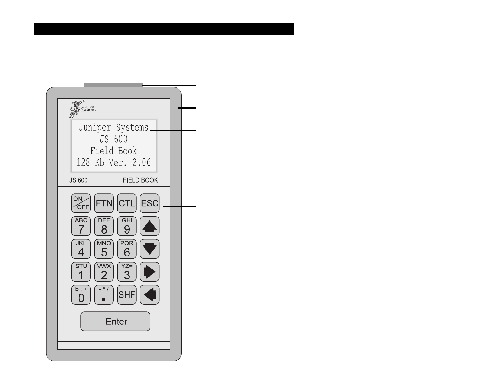
Enclosure
The FieldBook's internal components are enclosed in an impact-resistant polycarbonate case.
The case is sealed from moisture and dust with a neoprene rubber gasket, allowing the
FieldBook to be used in harsh field conditions. To ensure a proper seal, the gasket should be
cleaned periodically and replaced when it is worn out. Replacements are available from
Juniper Systems.
RS-232C Communication Port
Rugged, Sealed Case
Display
Ke yboard
Hardware Features Page 2-3
Page 10
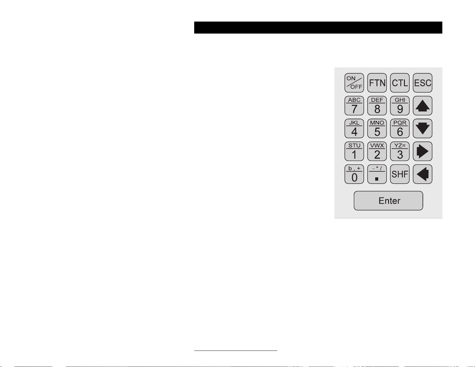
Keyboard
The FieldBook has a rugged, sealed, membrane keyboard with tactile response. There are 21
keys that are l/2 inch (1.27 cm) square. Key usage is described below.
On/Off Key: Toggles the FieldBook on and off.
Function Key (FTN): Used in custom program-
ming. In an application program, the function key
plus a numeric key can be used to spawn another
activity. For example, <FTN> + <1> can be used
to show a help menu for a data entry field. (See
Section 6, Programming the FieldBook, for details.)
Control Key (CTL): Enables you to type characters not included on the keyboard by entering an
ASCII code. The ASCII code is always a threedigit decimal number. Non-printable ASCII
characters will appear on the display as odd
symbols. A list of ASCII codes can be found at the
end of Section 7, PolyTools Program.
Escape Key (ESC): Returns you to the MODE?
prompt.
Alphanumeric Keys: To access the numbers
printed on the bottom of the keys, simply press
the key. To access the letters and symbols printed on the top of the keys, press the shift key
in combination with the alphanumeric key. For example, <SHF> <ABC/7> yields the letter
A. <SHF> <SHF> <ABC/7> yields the letter B.
Shift Key: Used to access the alphabetic characters and symbols printed on the top of the
keys. Each time the shift key is pressed, a vertical bar is shown on the display. If the shift key
is pressed 3 times in succession, 3 vertical bars are shown on the display.
Arrow Keys: Used to move the cursor around. Various operations use the arrow keys in
different ways. For example, the right and left arrow keys scroll through the directory when
you are in the File Directory Mode.
Enter Key: Causes the FieldBook to act on the command or data previously entered.
b (blank space): The small b (located on the top row of the 0 key) is used to create a blank
space. Press <SHF> <b/0>.
Page 2-4 Hardware Features
Page 11

Display
The FieldBook has a 4 line by 16 character liquid crystal display (LCD). Individual
characters are 0.187 x 0.116 inches (4.75 x 2.95 mm) in size. The display is 1 inch deep x 2.38
inches wide.
When the FieldBook is turned on, the message shown below flashes on the screen, giving
you the model number of the unit, the memory size, and the version number of the
operating system.
Juniper Systems
JS 600
FieldBook
256 Kb Ver. 2.06
Hardware Features Page 2-5
Page 12

Serial Communication Port
The FieldBook has a D type serial communication port with 25 pin contacts. The port is
sealed against moisture and fitted with a soft plastic plug to protect the pins. A slide lock
secures connectors when they are attached to the port.
The communication port handles the following:
❏ Serial RS-232C Communication Signals
The RS-232C serial port is used for transferring data between the FieldBook and a
computer, modem, printer, or another FieldBook. It can also read data from measurement
instruments which output information in RS-232C serial signals, such as bar code wands
and scanners, electronic balances, and water quality sensors.
❏ External Wakeup
The ring indicator can wake the FieldBook up from a powered-down state to collect data
based on an external event.
❏ Battery Charging
The main FieldBook batteries are charged through an AC battery charger which is
connected to the communication port.
❏ Digital Inputs and Outputs
The digital inputs can read data from digital sensors such as the Water Content
Reflectometer which measures the water content of porous media. The digital outputs can
be used in control applications to open switches for activating alarms or other devices.
❏ Clocked Serial Data Communications
Data can be read from sensors with a clocked serial output such as the Mitutoyo
Digimatic Caliper.
The connector pinouts are shown in Section 8, Technical Reference, Serial Communication Port
Connector Pinouts.
Page 2-6 Hardware Features
Page 13

Batteries
The FieldBook has two types of batteries:
- Ni-Cad Battery pack (main power supply)
- Lithium backup battery
▲ ▲
▲ Battery Pack
▲ ▲
The main power is provided by a rechargeable battery pack consisting of six AA nickelcadmium (Ni-Cad) batteries.
Battery Life
Battery life during manual data entry can be anywhere from 20 to 40 hours. For other
applications, battery life depends largely on what sensors are used and how much data
processing you are doing. Here are some examples of the current draw during typical tasks:
Activity Power Consumption
Powered down 0.25 mA
Waiting for input 12 mA
Processing data 25 mA
Fully charged Ni-Cad batteries have a life of 600 milliamp-hours. The formula for
calculating the expected battery life in hours follows:
H = 600/(.25A + 12B + 25C)
Where A = Fraction of time off
B = Fraction of time on and idle
C = Fraction of time processing
The shelf life of the battery pack is about three months (left in the FieldBook).
Battery Test Connector
The PW-645 Battery Test Connector is an optional accessory that allows you to check the
battery pack voltage for your FieldBook. If you have a Battery Test Connector, refer to the
Appendix, FieldBook Battery Test Connector, for instructions on how to use it. If you are
interested in ordering one, contact Juniper Systems.
Hardware Features Page 2-7
Page 14

What Happens as Battery Voltage Drops
As the FieldBook is operating, drawing from the main power supply, it monitors the battery
voltage. When the voltage drops below a pre-set threshold (voltage = 6.8), a low battery
message is displayed. Each time you press <ESC> or <Enter> while executing a program or
editing a data file, the following message is displayed:
CHARGE BATTERIES
CHARGE BATTERIES
CHARGE BATTERIES
CHARGE BATTERIES
Charge your batteries as soon as possible if you see this message. You usually have less than
an hour of operating time left (depending on your application).
The FieldBook turns itself off if the battery voltage drops below 6.0 volts. Each time you turn
it on, the same “CHARGE BATTERIES” message is displayed and the unit shuts down
again. If the FieldBook is not charged, the main battery is eventually discharged and the
lithium backup battery maintains all data and programs.
Recharging the Battery Pack
You should let the main batteries discharge just short of seeing the “LOW BATTERIES”
message to get the most out of each charging. For units that are in short or long-term storage,
the batteries should be charged about every six weeks.
The FieldBook comes with a SafeCharger battery pack charger (120 or 220 V AC) . To
charge the batteries, plug the AC charging adapter into a 120 V or 220 V power outlet
(depending on which model you have) and insert the connector into the serial port on top
of the FieldBook. Refer to the Appendix for more information about how to use the
SafeCharger.
Replacing the Battery Pack
Ni-Cad batteries can be recharged several hundred times, but the effective working life
continually decreases. Eventually the battery pack will need to be replaced. Replacement
battery packs are available from Juniper Systems.
Page 2-8 Hardware Features
Page 15

The backup battery maintains the memory while you are changing the battery pack.
Follow these steps to change the battery pack:
1) Turn the FieldBook off and lay it face down.
2) Loosen the six screws, pull the bottom of the case straight up, and rotate it over the top,
being careful not to pull on the cable connecting the top of the case to the bottom.
3) At the lower left corner of the board, disconnect the white molex connector that leads to
the battery pack.
4) Pull out the battery pack and replace it with a fresh pack.
5) Plug in the white molex connector of the new pack, being sure to align the pins properly.
6) Check the six hex standoffs which are mounted on the battery board and tighten them if
necessary. Be sure the holes in the battery holder are aligned with the holes in the hex
standoffs.
7) Before closing the case, check the rubber gasket for nicks, dirt, etc. Clean or replace it as
necessary to ensure a proper seal.
8) Be sure to seat the six aluminum washers in place properly. Insert and tighten the screws
until they are snug, but not over-tightened. The aluminum washers must not extend past the
case edge. (Replacement washers are available from Juniper Systems.)
▲ ▲
▲ Backup Battery
▲ ▲
The backup battery is a half-sized AA lithium cell. This battery maintains the FieldBook's
memory for 5 years, as long as the main batteries are kept charged.
What to Expect if Your Backup Battery Has Been Drained
If the backup battery is drained, memory is not maintained and program and data files are
lost.
Replacing the Backup Battery
The backup battery is not user-replaceable. You must return your Fieldbook to Juniper
Systems for replacement.
Hardware Features Page 2-9
Page 16

Page 2-10 Hardware Features
Page 17

Section 3
Operating
System
❏ Files
❏ Operating Modes
Page 18

Page 3-2 Operating System
Page 19

Files
The FieldBook has four types of files as described below:
❏ Data Files: Where your data are stored. Data files are divided into a three-dimensional
matrix of fields identified by the page, line, and column number. Data can be written into
a data file from the keyboard or an external sensor.
❏ Format Files: Contain the configuration for data files, including the number of columns
per line, the number of lines per page, column headings, and data types for each column.
❏ Polycode Program Files: Contain programs written in Polycode, the FieldBook's unique
programming language.
❏ System Program Files: Special files supplied by Juniper Systems. These files are primarily
used for specialized functions. For example, a system file is called to return the time from
the real-time clock.
File Names
A filename can be any string of ten or fewer ASCII characters. Numbers and blanks may be
leading or embedded in the string.
Examples: TREE.DAT TREE.FMT AB CD EF 123ABC TREE$
Passwords
You can protect your files against accidental deletion with a password. To do this, include a
slash (/) in the filename. Everything following the slash is the password. The filename,
counting the slash and the password, may not exceed ten characters.
Example: TREE.D/123 (TREE.D is the filename and 123 is the password)
You can edit a file with a password without supplying the password, however, you must
supply the password to erase it. (You need to remember your file passwords since there is
no way to display them!)
Hiding Files
You can hide a file by giving it a name that begins with @ (<CTL> <0> <6> <4> on the
FieldBook). A hidden file will not show up in the file directory unless it was the file most
recently opened. To edit or transmit a hidden file, key in the filename, including the @.
When you are finished with the file, you can hide it again by briefly opening and closing
another file so it will no longer be the last file opened.
Example: @DATA.PGM (this file will not show up in the file directory)
Number of Files
The maxinum number of files that will fit in the FieldBook directory is 255.
Operating System Page 3-3
Page 20

Operating Modes
All the functions of the FieldBook are accessed through the eight operating modes described
in the chart below.
Mode Display Function
0 EXECUTE PROGRAM Execute a Polycode program.
FILE:
1 EDIT 1,2,3 Edit a data, format, or program file.
DAT,FMT,PGM
2 XMIT SER 1,2,3 Transmit data, a file, or a memory image
DATA,FILE,MEM through the serial port.
3 LOAD SER 1,2,3 Load data, a file, or a memory image into
DATA,FILE,MEM the FieldBook from another computer or
FieldBook via the serial port.
4 FILE 1,2,3 Review the file directory, erase a file, or
DIR, ERA-F, ERA-D erase the data within a file.
5 SET 1,2 Set automatic logging or RS-232
AUTOLOG, PROTOCOL communication protocol parameters.
6 TEST 1,2,3,4 Test program execution, analog sensors,
PGM, ANA, DIG, MEM digital I/O, or memory.
7 MISC 1,2,3 Set system clock/calendar, perform battery
CLK, BAT, TERM check, or emulate a terminal.
When you turn the FieldBook on you will see a sign-on screen followed by the following
message:
MODE?
Simply enter the desired mode and submode number. For example, to edit a data file, enter
a 1 at the MODE prompt then press 1 again to select DAT (data) as the file type. You are
then prompted to select or enter a filename.
Page 3-4 Operating System
Page 21

The modes are described in detail in this section. Additionally, the use of the modes is also
described in the following sections of the manual:
Mode Described in This Section
0 Execute Program Section 6: Programming the FieldBook
1 Edit Section 4: Using the Built-In Spreadsheet Feature
Section 6: Programming the FieldBook
2 Transmit Section 5: Sending and Receiving Information
Section 7: PolyTools Application Development Program
3 Load Section 5: Sending and Receiving Information
Section 7: PolyTools Application Development Program
4 File Section 4: Using the Built-In Spreadsheet Feature
5 Set Section 5: Sending and Receiving Information
6 Test Section 6: Programming the FieldBook
Cursor Movement Commands
The arrow keys are used to move the cursor around to select mode options and view or edit
data in a file as described below:
Action Keyboard Entry
Move down one line ....................................................<Ð>
Move down 25 lines or to bottom of file ..................<SHF> <Ð>
Move down to bottom of file .....................................<SHF> <SHF> <Ð>
Move up one line ......................................................... <Ï>
Move up 25 lines .......................................................... <SHF> <Ï>
Move to top of file........................................................<SHF> <SHF> <Ï>
Move one column or parameter to the right ........... <Î>
Move all the way to the right on a line.....................<SHF> <Î>
Move one column or parameter to the left ..............<Í>
Move all the way to the left on a line .......................<SHF> <Í>
Delete a line .................................................................. <SHF> <SHF> <SHF> <Ï>
Insert a line....................................................................<SHF> <SHF> <SHF> <Ð>
Recover from keying errors........................................<Í>
Edit data ........................................................................Move to the data you want to edit, enter
the new data, and press <Enter>
View list of files............................................................ Press the <Í> or <Î> to scroll through
the list when asked for a filename.
Highlight desired filename and press
<Enter>.
Operating System Page 3-5
Page 22

▲ ▲
▲ Mode 0: Execute Program
▲ ▲
The Execute Program Mode is used to execute a Polycode program file. Instructions for
using Mode 0 follow.
Keyboard Entry Next Message Shown Action
<ON> MODE? Enter 0 for EXECUTE PROGRAM Mode.
0 EXECUTE PROGRAM Enter the filename or select it using the
FILE: right or left arrow key.
Filename The program is executed. What you see on the
<Enter> screen next depends on the program being run.
▲ ▲
▲ Mode 1: Edit
▲ ▲
The Edit Mode has three submodes: Mode 1-1 Edit Data File (EDIT DAT), Mode 1-2 Edit
Format File (EDIT FMT), and Mode 1-3 Edit Program File (EDIT PGM).
Mode 1-1, Edit Data File
The Edit Data File submode is used to create a new data file or change the contents of an
existing file. Note that if you are creating a new data file, a format file for it must exist or be
created first (Mode 1-2). Instructions for using Mode 1-1 follow.
Keyboard Entry Next Message Shown Action
<ON> MODE? Enter a 1 for EDIT Mode.
1 EDIT 1,2,3 Enter a 1 for submode DAT.
DAT,FMT,PGM
1 EDIT DATA Enter a new filename or select an existing
FILE: name using the right or left arrow key.
Filename FORMAT Enter the format filename for this data file
<Enter> FILE: (only needed for new files)
Filename P 1 HEADING The page number, line number, and column
<Enter> L 1 heading are displayed as specified by the
format file. In this example, you are on page
1, line 1. There is no data shown because this
is a new file.
If the data file already exists, the file pointer
remains at the place it was left at when the file
was last closed. You can now edit the data.
Page 3-6 Operating System
Page 23

Mode 1-2, Edit Format File
The Edit Format File submode is used to create new format files or edit an existing format
file. Instructions for using Mode 1-2 follow.
Keyboard Entry Next Message Shown Action
<ON> MODE? Enter a 1 for EDIT Mode.
1 EDIT 1,2,3 Enter a 2 for submode FMT.
DAT,FMT,PGM
2 EDIT FORMAT Enter a new filename or select an existing
FILE: name using the right or left arrow key.
Filename # OF COL. Enter the number of columns desired. The
<Enter> maximum allowed is 99.
Column Value LINES/PAGE Enter the number of lines per page desired.
<Enter> The maximum allowed is 9,999
Line Value FORMAT At this point, the following parameters can be
<Enter> C 1:N6 set up: data format, field width, and number
of decimal places. A default setting of N6 is
shown for new files. You can edit the setting
as follows: Format = Xn.d
Where: X = A for alphanumeric data
N for numeric data
F for floating point data
n = Total field width counting the
decimal point
d = Number of decimal places
(optional)
Format Value PROMPT Enter the desired column heading for column
<Enter> or just C 1:COL. 1 1 or accept the default heading of COL. 1 by
<Enter> to accept pressing <Enter>.
default value
Column Heading COL LEADER Enter the string of characters you want to
<Enter> or just C 1: precede the data in column 1 when it is
<Enter> to accept transmitted to a computer or printer. These
default value are usually blank spaces or delimeter
characters. The default is two blank spaces.
Operating System Page 3-7
Page 24

Keyboard Entry Next Message Shown Action
Leader Value FORMAT You are now asked to set up the format,
<Enter> or just C 2:N6 column heading, and column leader for
<Enter> to accept column 2, and so forth, just like you did for
the default value column 1, until all the columns are set up.
Guide to Formatting Files
❏You must set up a format file before you can set up a data file.
❏You cannot use the same name for a format file and a data file. However, you can use an
extension, i.e. LOG.DAT could be the data filename, and LOG.FMT the format filename.
❏After you have created a format file, you can edit the column formats, leaders, and
prompts. You cannot change the number of columns or the number of lines per page.
❏After you have created a data file that uses a format file, you can change only the column
leaders and prompts.
❏To combine the same kind of data gathered by several FieldBooks, have each user record
data using the same format.
❏The same format file can be assigned to different data files.
Mode 1-3, Edit Program File
The Edit Program File submode is used to create a new program file or edit an existing
program file. You can key a Polycode program directly into the FieldBook using Mode 1-3
or create the program using PolyTools or a text editor on a desktop computer and transfer
it to the FieldBook via the RS-232 port (refer to Section 6: Programming the FieldBook and
Section 7: PolyTools for details). Instructions for using Mode 1-3 follow.
Keyboard Entry Next Message Shown Action
<ON> MODE? Enter a 1 for EDIT Mode.
1 EDIT 1,2,3 Enter a 3 for submode PGM.
DAT,FMT,PGM
3 EDIT PROGRAM Enter a new filename or select an existing
FILE: name using the right or left arrow key.
Page 3-8 Operating System
Page 25

Keyboard Entry Next Message Shown Action
Filename END: OPCODE If the file already exists, you go directly
<Enter> L 1! 0 into the first line of the program. If you are
creating a new file, the screen shown in this
example is displayed. An END statement is
automatically supplied as the last instruction.
Key in the first line of your program, entering
either the opcode or mnemonic for the
instruction. For this example, let's say the
mnemonic is JNK.
JNK JNK: PARAMETER You are asked to enter a parameter if one is
<Enter> L 1! required for the instruction you entered. In
this example, the parameter required is the
jump location (line number).
Parameter END: OPCODE Enter the second line of the program, and so
<Enter> L 2! 0 on until you have entered all the instructions.
Guide to Editing Program Files
❏To insert a line in a program, press <SHF><SHF><SHF><Ð>, then enter the appropriate
opcode in place of the END statement.
❏If you insert or delete a line, remember to change line number references in the Polycode
parameter fields to match the renumbered program. You can use the NOP command as a
place holder in a list of Polycode instructions if you need to delete an instruction so you do
not have to change all the line number references in the subsequent lines in the program.
❏It is much easier to modify a Polycode program using PolyTools on the computer and
send the new version to the FieldBook for testing. The PolyTools mode “PolyTran” accepts
symbolic labels, then translates them to actual line numbers during compilation.
❏When you are satisfied the program file is correct, press <ESC> to compile the program.
Operating System Page 3-9
Page 26

▲ ▲
▲ Mode 2: Transmit
▲ ▲
The Transmit Mode has three submodes: Mode 2-1 Transmit Serial Data (XMIT SER DATA),
Mode 2-2 Transmit Serial File (XMIT SER FILE), and Mode 2-3 Transmit Memory Image
(XMIT SER MEM).
Mode 2-1 Transmit Serial Data
The Transmit Data submode is used to transmit the contents of a data file through the
RS-232C port to another device. Instructions for using Mode 2-1 follow.
Keyboard Entry Next Message Shown Action
<ON> MODE? Enter a 2 for XMIT SER Mode.
2 XMIT SER 1,2,3 Enter a 1 for submode DAT.
DAT, FILE, MEM
1 XMIT SER DATA Enter the filename containing the file to be
FILE: transmitted or select the name using the right
or left arrow key.
Filename L 1 P 1 CP=D “L 1 P 1” indicates the current line and page
<Enter> L=A R=B C=C S=D numbers. Data will be transmitted beginning
at the current line.
The bottom line shows the current settings of
the line request, repeat request, continuous
request, and stop request characters. In the
upper right corner is the current parameter
or the request character currently in force.
Guide to Transmitting Serial Data
❏ To initiate transmission, send a request character from the connected device or key it in
on the FieldBook's keyboard.
❏ The output format depends on the format file associated with the data file (refer to Mode
1-2) and data transmission protocol settings (refer to Mode 5-2).
❏ The checksum, if enabled, and the end-of-line sequence trail each line, including column
heading lines. One blank is output between the data line and the checksum. The blank is
not counted in calculating the checksum.
❏ Column headings are transmitted at the top of each page if transmit prompts (XMIT
PMTS) is set to Y in Mode 5-2.
❏ An end-of-page sequence is transmitted at the end of each page and an end-of-file
sequence is transmitted at the end of the file.
Page 3-10 Operating System
Page 27

Mode 2-2 Transmit Serial File
The Transmit Serial File submode is used to transmit a data, format, or program file through
the RS-232C port to another device. Instructions for using Mode 2-2 follow.
Keyboard Entry Next Message Shown Action
<ON> MODE? Enter a 2 for TRANSMIT Mode.
2 XMIT SER 1,2,3 Enter a 2 for submode FILE.
DAT, FILE, MEM
2 XMIT SER FILE Enter the filename to be transmitted or select
FILE: the name using the right or left arrow key.
Filename L 1 P 1 CP=D “L 1 P 1” indicates the current line and page
<Enter> L=A R=B C=C S=D numbers. For format and program files, the
page field is vacant. The entire file is
transmitted regardless of the line number.
The bottom line shows the current settings of
the line request, repeat request, continuous
request, and stop request characters. In the
upper right corner is the current parameter
or the request character currently in effect.
Output Formats
DAT
<filename>
<format filename>
< Data lines with column leaders embedded; checksums follow >
< if CHECKSUM is set to Y; column prompts not sent even if >
< XMIT PMTS set to Y. >
&
FMT
<filename>
<lines per page>
< Column number, period; then column format, column >
< prompt, and column leader, delimited by asterisks. >
&
PGM
<filename>
< Polycode program with line number ending with a period, opcode, >
< mnemonic, and parameter delimited by blanks. >
&
Operating System Page 3-11
Page 28

Guide to Transmitting Serial Files
❏ To initiate transmission, send a request character from the connected device or key it in
on the FieldBook's keyboard.
❏ Checksums, if enabled, follow each line in the body of a data file.
❏ An end-of-line sequence follows every output line. This is typically a carriage return
followed by a line feed.
❏ One blank is output between the data and the checksum, but it is not counted when
calculating the checksum
❏ An & is sent at the end of each file.
Mode 2-3 Transmit Serial Memory
The Transmit Serial Memory submode is used to transmit an image of the entire FieldBook
memory in hexadecimal form through the RS-232C port to a computer or another FieldBook
for reloading at a later time. Instructions for using Mode 2-3 follow.
Keyboard Entry Next Message Shown Action
<ON> MODE? Enter a 2 for TRANSMIT Mode.
2 XMIT SER 1,2,3 Enter a 3 for submode MEM.
DAT, FILE, MEM
3 XMIT SER MEM No action.
CP=D The bottom line shows the current settings of
L=A R=B C=C S=D the line request, repeat request, continuous
request, and stop request characters. In the
upper right corner is the current parameter
or the request character currently in force.
Guide to Transmitting Serial Memory
❏ To initiate transmission, send a request character from the connected device or key it in
on the FieldBook's keyboard.
❏ The first line of the output file contains the total number of bytes being saved, expressed
as a four-digit hexadecimal number.
❏ The final line is a four-digit hexadecimal checksum.
❏ The body of the memory image transmitted between the two checksums should be a block
of 64 character lines of hexadecimal numbers. If the lines are longer or shorter than 64
characters, the memory image has not transmitted correctly to the connected device.
Page 3-12 Operating System
Page 29

▲ ▲
▲ Mode 3: Load
▲ ▲
The Load Mode has three submodes: Mode 3-1 Load Serial Data (LOAD SER DATA), Mode
3-2 Load Serial File (LOAD SER FILE), and Mode 3-3 Load Serial Memory (LOAD SER
MEM).
Mode 3-1 Load Serial Data
The Load Serial Data submode is used to load data from another computer or FieldBook into
the FieldBook via the RS-232C port. Instructions for using Mode 3-1 follow.
Keyboard Entry Next Message Shown Action
<ON> MODE? Enter a 3 for LOAD SER Mode.
3 LOAD SER 1,2,3 Enter a 1 for submode DATA.
DAT, FILE, MEM
1 LOAD SER DATA Enter the filename the data is to be loaded to
FILE: or select the name using the right or left
arrow key.
Filename SET START LINE “L 1 P 1” indicate the current line and page
L 1 P 1 numbers. Data are loaded beginning at the
current line and page. Use the up and down
arrow keys to change the current page and
line number if desired.
To initiate loading, press <Enter>. Data scroll
across the screen as they are loaded.
Guide to Loading Serial Data
❏ Before you load data into the FieldBook, you must set the FieldBook up to receive
information. Refer to Section 5, Communications, for details.
❏ You must create a data file in the FieldBook before you can load the data.
❏ The input file must conform to one of the following formats:
- Column leader length and data format match the format of the destination file exactly
- Data fields are formatted to match destination file and are separated by commas;
null fields may be included
❏ Column prompts or headings cannot be included in the source file.
❏ The end-of-line may be denoted by a carriage return or an input line terminator.
❏ The line length in the input file may exceed the maximum input line length, but the
FieldBook ignores any characters in the transmitted lines which exceed the value set as the
maximum line length.
Operating System Page 3-13
Page 30

Mode 3-2 Load Serial File
The Load Serial File submode is used to load a data, format, or program file from another
computer or FieldBook into the FieldBook via the RS-232C port. Instructions for using Mode
3-2 follow.
Keyboard Entry Next Message Shown Action
<ON> MODE? Enter a 3 for LOAD SER Mode.
3 LOAD SER 1,2,3 Enter a 2 for submode FILE.
DAT, FILE, MEM
2 LOAD SER FILE The mating call is transmitted and the transfer
begins. Each line of information appears on
the lower line of the display as it is received.
Guide to Loading Serial Data
❏ Before you load a file into the FieldBook, you must set the FieldBook up to receive
information. Refer to Section 5, Sending and Receiving Information, for details.
❏ If you are loading a file which includes one or several program files, the message
“COMPILING” appears after each program file is loaded. If there are compilation errors
in a program, the FieldBook displays an error message and stops transmitting.
❏ The format file which corresponds to a given data file must preceed that data file during
file transfer.
❏ Lines are separated by a carriage return (default) or an input line terminator.
❏ Files are delimited by a key word (FMT, DAT, or PTM) on the first line of each file and an
ampersand (&) on the last line. A pound sign (#) is used instead of an & on the last line of
the last file loaded.
❏ The line length in the input file may exceed the maximum input line length, but the
FieldBook ignores any characters in the transmitted lines which exceed the value set as the
maximum line length.
Input Formats for Format, Data and Program Files
FMT
<filename>
<lines per page>
< Column number, period, column format, column prompt, >
< and column leader separated by any delimiter. Null column >
< leaders are acceptable. Example: 1. *A8* Species * * >
&
Page 3-14 Operating System
Page 31

DAT
<filename>
<format filename>
< Correctly formatted data fields separated by either column >
< leaders or commas; null fields acceptable. >
&
PGM
<filename>
< Line number followed by a period, opcode, mnemonic, >
< parameter (if required), semi-colon, and comments, where >
< opcode, semi-colon, and comments are optional. String >
< constants in the parameter field may be enclosed in quotes. >
< Control characters in the parameter field are expressed as >
< ^x where ^ is the control and x represents the alphanumeric >
< portion of the control character. Example: carriage return, >
< line feed is represented in control characters as ^M ^J. >
&
Mode 3-3 Load Serial Memory
The Load Serial Memory submode is used to load a FieldBook memory image into the
FieldBook from another FieldBook or computer through the RS-232C port. Instructions for
using Mode 3-3 follow.
❖ Caution: The entire contents of the FieldBook's memory is lost when a new memory image is
loaded. Before you load a new memory image, make sure you save copies of data and programs you
want to keep on another FieldBook or computer to be reloaded as needed.
Keyboard Entry Next Message Shown Action
<ON> MODE? Enter a 3 for LOAD SER Mode.
3 LOAD SER 1,2,3 Enter a 3 for submode MEM.
DAT, FILE, MEM
3 LOAD SER MEM The mating call is sent and the memory image
is loaded into the FieldBook.
Guide to Loading Serial Memory
❏We recommend that you reset the FieldBook using the @@SYS/RESET connector before
loading a memory image. Refer to Section 6, System Resest and @@SYS Inhibit Connector,
for details. Remember that the RESET connector erases everything stored in memory.
❏ Before you load a a memory image into the FieldBook, you must set the FieldBook up to
receive information. Refer to Section 5, Communications, for details.
❏ The input file (memory image) must have been generated by a FieldBook in Mode 2-3.
Operating System Page 3-15
Page 32

▲ ▲
▲ Mode 4: File
▲ ▲
File Mode is used to perform file maintenance tasks. There are three submodes: Mode 4-1
File Directory (FILE DIR), Mode 4-2 Erase File (FILE ERA-F), and Mode 4-3 Erase Data
(FILE ERA-D).
Mode 4-1 File Directory
The File Directory submode displays a directory of all data, format, and program files. The
name, type, size, associated format file, and the amount of space remaining in memory is
shown. Instructions for using Mode 4-1 follow.
Keyboard Entry Next Message Shown Action
<ON> MODE? Enter a 4 for FILE Mode.
4 FILE 1,2,3 Enter a 1 for submode DIR.
DIR, ERA-F, ERA-D
1 FILE: FILENAME The filenames are displayed one by one. Scroll
TYPE BYTES through them using the arrow keys. The
name of the file is shown as well as the
FMT FILENAME file type (format, data, or program), size in
bytes, and associated format file (for data
files).
To see how much space is available in
memory, continue to press the right or down
arrow key until all the files have been
displayed.
<Right Arrow> BYTES AVAILABLE The total number of remaining bytes is
or TOTAL: displayed as well as the portion available
<Down Arrow>, PGM/FMT: for program files, format files, and the
Repeatedly... directory.
Mode 4-2 Erase File
The Erase File submode is used to erase a data, format, or program file. Instructions for
using Mode 4-2 follow.
Keyboard Entry Next Message Shown Action
<ON> MODE? Enter a 4 for FILE Mode.
4 FILE 1,2,3 Enter a 2 for submode ERA-F.
DIR, ERA-F, ERA-D
Page 3-16 Operating System
Page 33

Keyboard Entry Next Message Shown Action
2 ERASE Enter the filename to be erased or select
FILE: the name using the right or left arrow key.
Filename ENTER PASSWORD If the file has a password, this screen is
<Enter> displayed. Key in the password.
Password SURE? (Y/N) Press Y if you are sure you want to erase the
<Enter> file. Pressing any other key prevents erasing.
Y DONE The file has been erased.
Guide to Erasing Files
❏ When a file is erased, it will no longer be listed in the file directory.
❏ To erase a format file, you must first erase the associated data files which use the format
file. If you do not, the FieldBook displays the message: FMT IN USE.
Mode 4-3 Erase Data
The Erase Data submode is used to erase the data in a data file without erasing the file
header information. Instructions for using Mode 4-3 follow.
Keyboard Entry Next Message Shown Action
<ON> MODE? Enter a 4 for FILE Mode.
4 FILE 1,2,3 Enter a 3 for submode ERA-D.
DIR, ERA-F, ERA-D
3 ERASE DATA Enter the filename you want to erase the data
FILE: from or select the name using the right or
left arrow key.
Filename SURE? (Y/N) Press Y if you are sure you want to erase the
<Enter> data from the file. Pressing any other key
prevents erasing.
Y DONE The data have been erased.
Guide to Erasing Data
❏ Although the data are erased, the file still exists and the filename will be listed in the file
directory.
Operating System Page 3-17
Page 34

▲ ▲
▲ Mode 5: Set
▲ ▲
The Set Mode has two submodes: Mode 5-1 Set Autolog (SET AUTOLOG), and Mode 5-2 Set
Communication Protocol (SET PROTOCOL).
Mode 5-1 Set Autolog
The Set Autolog submode is used to set the scan interval, units of time, and start time for
automatic data logging. Autolog is used to automatically turn the FieldBook on at a preset
time and start a Polycode program. The program can alert you (by beeping) that it is time
to enter data, or readings can be automatically taken from sensors with RS-232C output.
Instructions for using Mode 5-1 follow.
Keyboard Entry Next Message Shown Action
<ON> MODE? Enter a 5 for SET Mode.
5 SET 1,2 Enter a 1 for submode AUTOLOG.
1 LOG N/S/M/H Enter the units of time to be used for both the
L 1 !N autologging interval and start time as follows:
N = autolog not in use (default)
S = seconds
M = minutes
H = hours
Units of Time INTERVAL Enter the scan interval between executions of
<Enter> L 1!0 autolog, in the logging units selected. The
interval must be an integer less than sixty if
logging units are minutes or seconds, and less
than 24 if logging units are hours.
Scan Interval START TIME Enter the hour, minute, or second you
<Enter> L 1! want autologging to start (based on the
internal clock).
Start Time Autolog is now set. Press ESC to exit.
<Enter>
Guide to Setting Autolog
❏ Before autolog can be enabled, an autolog program must be written and stored in a
program file named AUTOLOG. Otherwise, the following message is displayed when the
FieldBook is turned off and autolog is returned to the default setting (off):
NO AUTOLOG PGM
AUTOLOG RESET
Page 3-18 Operating System
Page 35

❏ The autolog start time is based on the internal 24-hour system clock. For example, if your
logging units are minutes and your start time is 45, the FieldBook will execute the autolog
program the next time the minute field of the system clock reads 45.
Mode 5-2 Set Communication Protocol
The Communication Protocol submode is used to set up the following communication
parameters:
- Baud rate - Data bits
- Parity - Stop bits
- Duplex - Transmit prompts
- Line request character - Repeat request character
- Continuous request character - Stop request character
- Input line terminator - Input maximum length
- Transmit delay - Checksum
- End of line sequence - End of page sequence
- End of file sequence - Mating call
Characteristics of the FieldBook's internal beeper are also set up in this mode.
Use the left Í and right Î arrow keys to view each of the parameters. Instructions for using
Mode 5-2 follow.
Keyboard Entry Next Message Shown Action
<ON> MODE? Enter a 5 for SET Mode.
5 SET 1,2 Enter a 2 for submode PROTOCOL.
2 BAUD Enter the desired baud rate (bits transmitted
L 1!_9600 or received per second). Valid entries are: 300,
600, 1200, 2400, 4800, 9600 (default), and
19200.
Baud Rate DATA BITS 7/8 Enter the number of data bits desired per
<Enter> or L 1!8 word. Valid entries are 7 and 8 (default).
just <Enter> to
accept default
Data Bits PARITY E/O/N Enter the parity settings for transmitted data.
<Enter> or L 1!N The FieldBook does not check parity when
just <Enter> to receiving data. Valid entries are:
accept default E = Eighth parity bit set for even parity
O =Eighth parity bit set for odd parity
N =No parity (default)
Operating System Page 3-19
Page 36

Keyboard Entry Next Message Shown Action
Parity <Enter> STOP BITS 1/2 Enter the desired number of stop bits. Valid
or just <Enter> L 1!1 entries are 1 (default) and 2.
to accept defaults
Stop Bits DUPLEX Enter the duplex setting for transmissions.
<Enter> or just L 1!H Valid entries are:
<Enter> to H =Half duplex (default): in terminal mode,
accept default the character is displayed on the screen
before being transmitted
F = Full duplex: in terminal mode, the
character is displayed on the screen
only after being echoed back by the
computer
Duplex <Enter> XMITS PMTS Y/N If you wish to transmit the column prompts
or just <Enter> L 1!N at the top of each page, enter a Y for yes. The
to accept default default is N, no column prompts.
Y <Enter> or LINE REQ A line request character can be designated as
just <Enter> to L 1!A any ASCII character. The FieldBook interprets
accept default a line request character received from either
the keyboard or the I/O port as a prompt to
transmit one line. The default is A.
Line request REPEAT REQ A repeat request character can be designated
character L 1!B as any ASCII character. The FieldBook
<Enter> or just inteprets a repeat request character received
<Enter> to from either the keyboard or the I/O port as a
accept default prompt to transmit the last line transmitted
again. The default is B.
Repeat request CONTINUOUS REQ A continuous request character can be
character L 1!C designated as any ASCII character. The
<Enter> or just FieldBook interprets a continuous request
<Enter> to character received from either the keyboard
accept default or the I/O port as a prompt to transmit the
remainer of the data without pausing between
lines. The default is C.
Page 3-20 Operating System
Page 37

Keyboard Entry Next Message Shown Action
Continuous req. STOP REQ A stop request character can be designated as
character L 1!D any ASCII character. The FieldBook intreprets
<Enter> or just a stop request character received from either
<Enter> to the keyboard or the I/O port as a signal to
accept default interrupt transmission at the end of the
current line. The default is D.
Stop request INP LINE TERM An input line terminator can be designated.
character L 1!Å While receiving data, the FieldBook watches
<Enter> or just for the input line terminator and interprets it
<Enter> to as the end of the line of data. The default is a
accept default carriage return. Carriage return and line feed
characters are represented by Å symbols
on the display.
Input line INP MAX LENGTH The maximum line length can be designated.
terminator L 1!95 The FieldBook terminates a line of incoming
<Enter> or just data after it reads in the number of characters
<Enter> to given by the input maximum length,
accept default provided it has not already read in a carriage
return or the input line terminator. The
default is 95, which is maximum.
Max. line TRANSMIT DELAY Enter the time, in tenths of a second, you want
length <Enter> L 1!0 the FieldBook to wait before responding to a
or just <Enter> request to transmit data. The default is 0.
to accept default
Transmit delay CHECKSUM Y/N Enter a Y if you want to compute and transmit
<Enter> or just L 1!N a checksum at the end of each line of data.
<Enter> to The checksum is calculated as the sum of all
accept default ASCII codes in the line. It does not include the
end of line sequence or the checksum itself.
The default is N, no checksum.
Y <Enter> or END OF LINE SEQ An end-of-line sequence can be designated
just <Enter> to L 1!Å that the FieldBook transmits at the end of
accept default each line of data. A character or sequence of
up to ten characters can be used. The default
setting is a carriage return followed by a line
feed.
Operating System Page 3-21
Page 38

Keyboard Entry Next Message Shown Action
End-of-line END OF PAGE SEQ An end-of-page sequence can be designated
sequence <Enter> L 1!Å that the FieldBook transmits at the end of
or just <Enter> to each page. A character or sequence of up to
accept default ten characters can be used. The default setting
is a carriage return followed by a line feed.
End-of-page MATING CALL A mating call can be designated that the
sequence <Enter> L 1!A FieldBook will send to the connected device
or just <Enter> to whenever it is ready to accept another line of
accept default data. A character or sequence of up to ten
characters can be used. The default is A.
Mating call BEEP TONE The pitch of the FieldBook's beep can
<Enter> or L 1!55 be set, ranging from 1 (lowest pitch) to 80
just <Enter> to (highest pitch). The default is 55.
accept default
Beep tone BEEP TIME The duration of the FieldBook's beep can be
<Enter> or L 1!10 set in hundredths of a second, ranging from
just <Enter> to 0 to 99. The default is 10. To turn the beep off,
accept default set the beep time to 0.
Beep time
<Enter> or
just <Enter> to
accept default
▲ ▲
▲ Mode 6: Test
▲ ▲
The Test Mode is used to test software, hardware, or memory. There are four submodes:
Mode 6-1 Test Program (TEST PGM), Mode 6-2 Test Analog (TEST ANA), Mode 6-3 Test
Digital I/O (TEST DIG), and Mode 6-4 Test Memory (TEST MEM).
Mode 6-1 Test Program
The Test Program submode is used to test a Polycode program. You can step through
instructions in a program line-by-line. Mode 6-1 also allows you to view the values in the
numeric stack and user registers after each instruction. To view these registers, use the
arrow keys as follows:
Action Keyboard Entry
See the next register ................................................. <Î>
Jump ahead ten registers.........................................<SHF> <Î>
Jump ahead 19 registers .......................................... <SHF> <SHF> <Î>
Jump ahead 28 registers .......................................... <SHF> <SHF> <SHF> <Î>
Page 3-22 Operating System
Page 39

Action Keyboard Entry
Jump back to previous register .............................. <Í>
Jump back ten registers ........................................... <SHF> <Í>
Jump back 19 registers.............................................<SHF> <SHF> <Í>
Jump back 28 registers.............................................<SHF> <SHF> <SHF> <Í>
Execute line ...............................................................<Ð>
Input a value, then execute line ............................. <Ð> <VALUE> <Enter>
Instructions for using Mode 6-1 follow.
Keyboard Entry Next Message Shown Action
<ON> MODE? Enter a 6 for TEST Mode.
6 TEST 1,2,3,4 Enter a 1 for submode PGM.
PGM, ANA, DIG, MEM
1 TEST PROGRAM Enter the filename to be tested or select
FILE: the name using the right or left arrow key.
Filename 1 OPN DATPGM The top line shows the program line number
<Enter> REG A __.00000000 (1), mnemonic (OPN), and parameter
(DATPGM). The bottom line shows the
register letter (A) and contents prior to
executing the instruction (.00000000).
<Down Arrow>
to execute line or
<Right Arrow> to
view registers
At this point, you can view the other registers
using the right arrow key or press the down
arrow key to execute line 1 and move on to
line 2. If an instruction requires input, key it
in and press <Enter>. Continue to execute
your program until you have viewed each
line.
Operating System Page 3-23
Page 40

Guide to Testing Programs
❏ To change the contents of a register, bring the register onto the screen, enter the new
value, and press <Enter>.
❏ Keep in mind as you are testing your program that the FieldBook has not yet executed the
instruction shown on the display. In other words, the status of the registers you see is
their condition before the instruction is executed. To execute the current statement, press
the down arrow key.
❏ You cannot pass beyond JNK or JKY instructions while testing a program in mode 6-1.
Substituting an NOP instruction temporarily for either instruction allows you to complete
testing of the program.
Mode 6-2 Test Analog
The Test Analog submode is not applicable to this version of the FieldBook.
Mode 6-3 Test Digital
The Test Digital submode is used to test digital inputs and outputs. Instructions for using
Mode 6-3 follow.
Keyboard Entry Next Message Shown Action
<ON> MODE? Enter a 6 for TEST Mode.
6 TEST 1,2,3,4 Enter a 3 for submode DIG.
PGM, ANA, DIG, MEM
3 INPUTS 1234 The top line shows which of the four input
OUTPUTS 3 channels are presently high on the serial
connector. If no external device is attached,
numbers 1 through 4 are displayed. The
second line shows which of the three output
channels are presently high. You can toggle
the lines from high to low by pressing their
corresponding numbers on the keyboard.
Mode 6-4 Test Memory
The Test Memory submode is used to test the Random Access Memory and make sure it is
working properly. Instructions for using Mode 6-4 follow.
Keyboard Entry Next Message Shown Action
<ON> MODE? Enter a 6 for TEST Mode.
6 TEST 1,2,3,4 Enter a 4 for submode MEM.
PGM, ANA, DIG, MEM
Page 3-24 Operating System
Page 41

Keyboard Entry Next Message Shown Action
4 PROM # The prom number is a four-digit checksum
RAM TEST that refers to the operating system version
contained in your FieldBook.
PROM # As the RAM is tested, memory addresses
RAM GOOD flash on the display. If the memory is good,
the messge RAM GOOD is displayed. If there
is a problem with the memory, the message
RAM BAD appears. Immediately download
all files from the Fieldbook to a computer to
avoid losing information and contact our
customer service department.
▲ ▲
▲ Mode 7: Miscellaneous
▲ ▲
The Miscellaneous Mode has three submodes: Mode 7-1 Misc Clock (MISC CLK), Mode 7-2
Misc Battery (MISC BAT), and Mode 7-3 Misc Terminal (MISC TERM).
Mode 7-1 Misc Clock
The Misc. Clock submode is used to set the FieldBook's internal clock/calendar. Instructions
for using Mode 7-1 follow.
Keyboard Entry Next Message Shown Action
<ON> MODE? Enter a 7 for MISC Mode.
7 MISC 1,2,3 Enter a 1 for submode CLK.
CLK, BAT, TERM
MO DA HR MN SC The month (MO), day (DA), hour (HR),
7 31 12 10 47 minutes (MN), and seconds (SC) are
displayed on a 24 hour clock basis. To change
a field, use the right arrow key to get to the
field, key in the new number, and press
<Enter>.
Guide to Setting the Clock
❏ Seconds run continually and cannot be set. If you change the minutes (MN) field, the
seconds (SC) field is automatically reset to zero.
Operating System Page 3-25
Page 42

Mode 7-2 Misc Batteries
The Misc Batteries submode is not applicable to this version of the FieldBook.
Mode 7-3 Misc Terminal
In the Misc Terminal submode, the FieldBook functions as a terminal to another RS-232C
device, such as a printer, computer, or another FieldBook. Instructions for using Mode 7-3
follow.
Keyboard Entry Next Message Shown Action
<ON> MODE? Enter a 7 for MISC Mode.
7 MISC 1,2,3 Enter a 3 for submode TERM.
CLK, BAT, TERM
3 _ A blank screen is initially displayed. As
information is received from the connected
device, it is displayed on the FieldBook.
Information keyed in on the FieldBook
keyboard is sent to the connected device.
Guide to Using the FieldBook as a Terminal
❏ Before you can use the FieldBook as a terminal, you must set the FieldBook up to receive
and send information. Refer to Section 5, Sending and Receiving Information, for details.
❏ This mode can be used to test the communication link between the FieldBook and another
RS-232C device.
Page 3-26 Operating System
Page 43

Section 5
Sending and
Receiving
Information
❏ Setting Up Communication With Another Device
❏ Transmitting Information to Another Device
❏ Loading Information From Another Device
Page 44

Page 5-2 Sending and Receiving Information
Page 45

Setting Up Communication With Another Device
You can transmit data and files directly from the FieldBook
to another device, including a computer, printer, terminal,
or another FieldBook using the Transmit Modes. You
can also load information from another device to
the FieldBook using the Load Modes. The Transmit
Modes and Load Modes complement each other
exactly.
To get the FieldBook to communicate with another device, you must complete these tasks:
- Make the appropriate hardware connections with an RS-232C cable.
- Set up the communication protocol parameters on the FieldBook and the other device so
that a communication link can be established. If you are communicating with a computer,
you can use the PolyTools transfer option, the Windows Terminal program, or any
commercially available communication program.
▲ ▲
▲ Hardware Connections
▲ ▲
To connect the devices together, you must have a properly wired RS-232C communication
cable. The appropriate cable is available as an optional accessory from Juniper Systems. A
schematic of this cable can be found in the Appendix.
To connect the devices, plug the FieldBook end of the connector into the RS-232C
communication port on the top of the FieldBook and the other end into the communication
port on the other device.
▲ ▲
▲ Communication Protocol Parameters
▲ ▲
The next step is to ensure that the sending and receiving devices speak the same language.
The values for baud rate, data bits, parity, and stop bits on the FieldBook and the other
device must match to establish the communication link. You can change these parameters to
match the settings on the other device or vice versa. The duplex and communication port
settings do not have to match. A description of these parameters follows.
Baud Rate
The FieldBook will send or receive at rates of 300, 600, 1200, 2400, 4800, 9600, and 19200 bits
per second. The default is 9600.
Data Bits
The FieldBook can send or receive either 7 or 8 bit characters. The default setting is 8.
Stop Bits
The FieldBook can send or receive either 1 or 2 stop bits. The default setting is 1.
Sending and Receiving Information Page 5-3
Page 46

Parity
The parity setting specifies how the FieldBook sets the bits before sending data. Valid entries
include:
E = Even parity
O = Odd parity
N = No parity (default)
Duplex
Valid duplex settings for transmissions include:
H = Half duplex (default): in terminal mode, characters are displayed on the screen
before being transmitted
F = Full duplex: in terminal mode, characters are displayed on the screen only after being
echoed back by the computer
Communication Port
There is one RS-232C communication port on the FieldBook (COM1). Select either COM1 or
COM2 on your computer, depending on which port the cable is connected to.
Setting up the Parameters on the FieldBook
On the FieldBook, the communication parameters are set up in Mode 5-2, Set Communication Protocol. Refer to Section 3, Operating System, Operating Modes, Mode 5: Set, for details on
how to use Mode 5-2.
Setting up the Parameters on a Computer
PolyTools
You can use PolyTools to set up the communication protocol parameters on the computer.
The instructions in this manual assume you are using PolyTools. See Section 7, PolyTools
Application Development Program, Transfer Files, for details.
Windows Terminal Program
If you have Windows on your computer, you can use the Windows Terminal program to set
up communication with the FieldBook. In addition to the parameters listed previously, set
up the following parameters to match the FieldBook's default settings:
Settings Menu
Communications Sub-menu
Flow Control: ● None
Text Transfers Sub-menu
Flow Control: ● Line at a Time.
Transfer a Line at a Time: ● Wait for Prompt String: A
(Note: The Wait for Prompt String must be equal to the
mating call on the FieldBook.)
Page 5-4 Sending and Receiving Information
Page 47

Other Programs
You can also use a commercially available communication program or write your own.
▲ ▲
▲ Testing Your Setup in Terminal Mode
▲ ▲
A good way to test your hardware connections and communication protocol settings is to
put the FieldBook in Mode 7-3, Terminal Mode. The FieldBook behaves like a terminal,
sending characters keyed in on the keyboard out the communication port and displaying
characters received from the other device. Refer to Section 3, Operating System, Operating
Modes, Mode 7: Misc, for details on how to use Mode 7-3.
If the Device is a Printer or Terminal:
Hit a few keys on the FieldBook followed by <Enter>. The string of characters should be
printed out by the printer or displayed on the terminal screen. Likewise, characters typed on
the terminal keyboard should appear on the FieldBook's display.
If the Device is a Time-share Computer via Modem:
Call up your computer. You should be able to key in the account number and password.
If the Device is a Personal Computer:
PolyTools has a mode called Test Terminal Mode you can use to test the communication
setup between the Fieldbook and a computer. Refer to Section 7, PolyTools, Transferring Files,
Test Terminal Mode for details.
The Windows Terminal program can also be used to test communication.
Troubleshooting
If you see nonsense characters:
- Make sure that the baud rate, parity, stop bits, and number of data bits for the two devices
match.
If you see nothing at all:
- Check the cable, making sure both connectors are plugged firmly in place. If you built your
own cable, you may have a wiring problem.
- Make sure that the communication port is assigned properly on the computer.
Sending and Receiving Information Page 5-5
Page 48

Transmitting Information to Another Device
Once you have established communication, you can set the FieldBook up to transmit
information to the other device. The FieldBook has three Transmit Modes:
Mode 2-1, Transmit Serial Data: Sends data from a data file
Mode 2-2, Transmit Serial File: Sends an entire format, data, or program file, including
filename and type
Mode 2-3, Transmit Serial Memory: Sends an image of the entire FieldBook memory in
hexadecimal form
In addition to using the Transmit Modes, you can transmit data using a Polycode program.
▲▲
▲
Transmission Communication Parameters
▲▲
Before you can transmit information from the FieldBook to another device, you need to set
up the transmission communication parameters on the FieldBook. This is done in Mode 5-2,
Set Communication Protocol. Refer to Section 3, Operating System, Operating Modes, Mode 5:
Set, for details on how to use Mode 5-2. A description of the parameters follows.
Line Request Character
The FieldBook interprets the line request character when received from the keyboard or the
RS-232C port as the signal to send one line of data. Any single ASCII character can be used.
The device sends the line request character, then reads and stores the line of data sent in
response by the FieldBook. The default character is A.
Repeat Request Character
The FieldBook inteprets the repeat request character when received from the keyboard or
the RS-232C port as the signal to retransmit whatever line was last transmitted. This parameter is useful if the FieldBook transmits over phone lines to a computer that can detect
transmission errors. Any single ASCII character can be used. The default character is B.
Continuous Request Character
The FieldBook interprets the continuous request character when received from the keyboard
or the RS-232C port as the signal to transmit data continuously until either the end-of-file is
reached or until it receives another valid request character. This is the request character most
often used. If you are sending data to a computer, use the continuous request only if you are
controlling data flow with the RS-232C handshaking lines. Any single ASCII character can
be used. The default character is C.
Stop Request Character
The FieldBook recognizes the stop request character as the signal to stop transmission at the
end of the current line. Any single ASCII character can be used. The default character is D.
Page 5-6 Sending and Receiving Information
Page 49

End-of-Line Sequence
The FieldBook transmits the end-of-line sequence at the end of each line. The end-of-line
sequence can be up to 10 ASCII characters long. The default is a carriage return followed by
a line feed (displayed as Å ).
End-of-Page Sequence
The FieldBook transmits the end-of-page sequence after transmitting the last line on a page
and the end-of-line sequence, subject to the following:
- When transmitting a response to a continuous request character, the FieldBook sends the
end-of-page sequence after the last end-of-line sequence and before the data in the first line
of the following page.
- If prompted line-by-line, the FieldBook sends the end-of-page sequence in response to a
line request. It does not tack on the end-of-line sequence.
The end-of-page sequence can be up to ten ASCII characters long. If you are transferring
data to a printer and want it to page up, set the end-of-page sequence to the ASCII form feed
by pressing <CTL> <0> <1> <2> <Enter>. If you don't want anything transmitted, press
<CTL> <0> <0> <0> <Enter>. The default setting is a carriage return followed by a line feed
(displayed as Å ).
End-of-File Sequence
The FieldBook sends the end-of-file sequence after it has transmitted the last line of a file,
subject to the following:
- If prompted with the continuous request character, the FieldBook transmits the end-of-file
sequence automatically.
- If transmitting line-by-line, the end-of-file sequence is sent in response to a line request.
The end-of-file sequence can be up to ten ASCII characters long. If you don't want anything
transmitted, press <CTL> <0> <0> <0> <Enter>. The default setting is carriage return
followed by a line feed (displayed as Å ).
Transmit Prompts
If you want the column prompts to appear at the top of each page, set this parameter to Y
(yes). Column prompts are transmitted only in Mode 2-1. The default is N (no).
Transmit Delay
The transmit delay is the amount of time, in tenths of a second, the FieldBook waits before
responding to a request character. A computer uses this time to prepare to receive data from
the FieldBook. A delay is especially useful when sending data to a printer with a limited
buffer size. The default setting is 0.
Sending and Receiving Information Page 5-7
Page 50

Checksum
A checksum is the sum of ASCII codes for all the characters in a line of data, excluding the
checksum itself. It provides a transmission error check if your computer is programmed to
calculate its own sum on the incoming characters. If the sum on your computer does not
match the sum sent by the FieldBook, an error has occurred. Your computer will request
retransmission of the line by sending the repeat request to the FieldBook. If you want a
checksum, set this parameter to Y (yes). The default setting is N (no).
▲▲
▲
Coordinating the Devices
▲▲
Transmitting to a Printer
Transmitting data to a printer is usually simple. Set the end-of-line sequence to a carriage
return, line feed; or just a carriage return if your printer automatically supplies a line feed
whenever it receives a carriage return. Turn the printer on and make sure the paper is
properly installed.
Transmitting to a Computer
Via PolyTools
If you are using PolyTools to communicate with the FieldBook, execute PolyTools on the
computer and get into the Transfers Files, Upload From FieldBook option. See Section 7,
PolyTools Application Development Program, Transfer Files, for details.
Via Windows Terminal Program
If you are using the Windows Terminal program to communicate with the FieldBook,
execute the program and get into the Transfers, Receive Text File option. Type in the name of
the file you are transferring from the FieldBook and press OK.
Via a Communication Package
If you are using a communication program, refer to the instructions included with the
program.
To a Computer With Standard Software Handshaking
Most computers use standard communication protocol to control the flow of data. The
FieldBook supports a subset of the XON/XOFF communication protocols.
A computer using the XON/XOFF protocol issues XON to indicate that it is ready to accept
data and XOFF to stop data transmission. XON and XOFF are ASCII characters DC1 (ASCII
decimal 17) and DC3 (ASCII decimal 19), respectively. If your computer uses this protocol,
set the FieldBook's continuous request character to DC1 and stop request character to DC3.
When the computer issues XON, the FieldBook begins to transmit data continuously.
To a Computer Without a Program to Provide Communication or Standard Software Handshaking
If your computer does not have a program to provide communication through the serial
port, you have to write one.
Page 5-8 Sending and Receiving Information
Page 51

Sample program:
10 OPEN COM1: AS #1
20 OPEN DATAFILE AS #2
30 PRINT #1, A
40 INPUT #1, DATA$
50 IF DATA$ = EOF THEN END
60 PRINT #2, DATA$
70 GO TO 30
80 END
The program transmits A as the line request character and checks each input line to see if it
is the end-of-file character string. The FieldBook responds with a line of data followed by the
end-of-line sequence.
Transmitting to Another FieldBook
Sending FieldBook
The transmission communication parameters must be set up on the sending FieldBook in
Mode 5-2. To transmit information, the sending FieldBook must be in Mode 2-1 to transmit
data, 2-2 to transmit a file, or 2-3 to transmit a memory image, as outlined in the following
pages.
Receiving FieldBook
The communication parameters for loading must be set up on the receiving FieldBook in
Mode 5-2. To load information, the receiving FieldBook must be in Mode 3-1 to load data,
3-2 to load a file, or 3-3 to load a memory image. Refer to Loading Information From Another
Device later in this section.
▲▲
▲
Mode 2-1: Transmitting Data From a Data File
▲▲
You can transmit data from a data file to a computer, printer, or another FieldBook using
Mode 2-1, Transmit Serial Data.
After you are sure that the FieldBook and the other device are communicating properly,
enter Mode 2-1 on the FieldBook. The following screen is displayed:
XMIT SER DATA Enter the filename containing the data to be
FILE: transmitted or select the name using the right or
left arrow key.
Sending and Receiving Information Page 5-9
Page 52

L 1 P 1 CP=D “L 1 P 1” indicates the current line and page
L=A R=B C=C S=D numbers. The bottom line shows the current settings
of the line request, repeat request, continuous
request, and stop request characters. In the upper
right corner is the current parameter for the request
character currently in force.
Data are transmitted beginning at the active line. Position yourself at the beginning of the
file or selectively transmit sections of the file. Initiate transmission by keying in the line
request or continuous request character, or executing your computer program so that it
sends one of the request characters. The line number on the display is updated as each line is
transmitted.
Refer to Section 3, Operating System, Operating Modes, Mode 2:Transmit for more details on
using Mode 2-1.
▲▲
▲
Mode 2-2: Transmitting a Serial File
▲▲
You can transmit a format, data, or program file to a another device using Mode 2-2,
Transmit Serial File.
After you are sure that the FieldBook and the other device are communicating properly,
enter Mode 2-2 on the FieldBook. The following screen is displayed:
XMIT SER FILE Enter the filename to be transmitted or select
FILE: the name using the right or left arrow key.
L 1 P 1 CP=D “L 1 P 1” indicates the current line and page
L=A R=B C=C S=D numbers. For format and program files, the page
field is vacant. The entire file is transmitted
regardless of the line number. The bottom line
shows the current settings of the line request, repeat
request, continuous request, and stop request
characters. In the upper right corner is the current
parameter for the request character in force.
Initiate transmission by keying in the line request or continuous request character, or executing your computer program so that it sends one of the request characters. The line number
on the display is updated as each line is transmitted.
Page 5-10 Sending and Receiving Information
Page 53

Following are sample printouts of each type of file:
Format File FMT
FIELDFMT
14
1. *A4*ROW1**
2. *N5.1*HEIGHT**
3. *N5.1*%KILL**
4. *N5.1*LAI**
&
Data File DAT
FIELDDAT
FIELDFMT
ROW1 14.0 25.0 1.5
ROW2 12.0 30.0 2.1
&
Program File PGM
FIELDPGM
1. OPN FIELDDAT ;Open the data file FIELDDAT
2. ENT ;Enter the row value
3. ICP ;Move column pointer to Height column
4. ENT ;Enter the Height value
5. END ;End
&
Refer to Section 3, Operating System, Operating Modes, Mode 2:Transmit for more details on
using Mode 2-2.
▲▲
▲
Mode 2-3: Transmitting a Memory Image
▲▲
Mode 2-3 is used to transmit a memory image from the FieldBook to a computer or another
FieldBook. All the files, operating system variables, attributes, user registers, etc. are sent.
The memory image can be reloaded onto the FieldBook as needed. This feature is also useful
for loading a clone of one FieldBook's memory image onto another FieldBook.
Transmitting a Memory Image to Another FieldBook
If you are transmitting a memory image to another FieldBook, the FieldBooks must have
identical memory sizes. Set the communication parameters up as follows:
- Set the mating call on the receiving FieldBook to match the line request character on the
transmitting FieldBook.
- Set the input line terminator on the receiving FieldBook to match the end-of-line sequence
on the transmitting FieldBook.
Sending and Receiving Information Page 5-11
Page 54

Operating Mode 2-3
After you are sure that the FieldBook and the other device are communicating properly,
enter Mode 2-3 on the FieldBook. The following screen is displayed:
XMIT SER MEM
Then:
CP=D The bottom line shows the current settings of the
L=A R=B C=C S=D line request, repeat request, continuous request, and
stop request characters. In the upper right corner is
the current parameter for the request character
currently in force.
Initiate transmission by keying in the line request or continuous request character, or executing your computer program so that it sends one of the request characters.
Refer to Section 3, Operating System, Operating Modes, Mode 2:Transmit for more details on
using Mode 2-3.
Page 5-12 Sending and Receiving Information
Page 55

▲▲
▲
Transmitting Under Polycode Program Control
▲▲
If Transmit Mode 2 does not meet your needs, you can write your own custom transmitting
program in Polycode. For instance, if you wanted to transmit your data in some sorted
order, you could create an index file in the FieldBook, then write a program to transmit lines
in the order they appear in the index file.
A sample Polycode program to transmit a file line by line follows:
OPN FIELDDAT ;Open data file
CON 1 ;Load constant = 1 in A register
PSH ;Load constant = 1 in B register
PSH ;Load constant = 1 in C register
SLC ;Set file pointer to top of file
LCT ;Load total number of lines in B register and total
number of columns in A register
POP ;Load total number of lines in A register
STO 10 ;Store total number of lines in register 10
LOOP: TRL ;Start loop, transmit line of data
DJZ 10, DONE ;If register 10 = 0 then go to label DONE
ILP ;Increment line pointer (go to next line in data file),
JMP LOOP ;Jump to start of loop
DONE: CDS 0, 64 ;Label DONE, clear FieldBook display
WID 16 ;Set display width to 16
VUM "Transmission" ;View message
CDS 16, 0 ;Set cursor to beginning of second line
VUM "Complete" ;Show message
END ;Quit program
See Section 6, Programming the FieldBook, for details on how to write a Polycode program.
Sending and Receiving Information Page 5-13
Page 56

Loading Information From Another Device
The FieldBook has three Load Modes for loading information from a computer or another
FieldBook:
Mode 3-1 Load Serial Data: Loads data into an existing data file
Mode 3-2, Load Serial File: Loads a data, format, or Polycode program file
Mode 3-3, Load Serial Memory: Loads a FieldBook memory image
▲▲
▲
Communication Parameters for Loading
▲▲
Before you can load information onto the FieldBook from another device, you need to set up
the communication parameters for loading on the FieldBook. This is done in Mode 5-2, Set
Communication Protocol. Refer to Section 3, Operating System, Operating Modes, Mode 5: Set,
for details on how to use Mode 5-2. A description of the parameters follows:
Mating Call
The FieldBook sends a mating call to the connected device when it is ready to accept another
line of information. The mating call can be a string of 1 to 10 characters (1 is most efficient).
The default character is A.
Input Line Terminator
The input line terminator signals the FieldBook that the end of the data line being loaded has
been reached. It is a single character, usually set to a carriage return, which is the default.
Input Maximum Length
The input maximum length is the maximum number of characters the FieldBook will accept
in an incoming line of information. The maximum allowable number is 95, which is the
default.
Default Parameters
The default settings for the communication parameters are adequate most of the time. If you
decide to change them, remember that the FieldBook identifies the end of a line as the first
occurrence of one of the following:
- A carriage return
- The input line terminator
- The maximum number of characters have been transmitted
Page 5-14 Sending and Receiving Information
Page 57

▲▲
▲
Coordinating the Devices
▲▲
Loading From a Computer
Via PolyTools
If you are using PolyTools to communicate with the FieldBook, execute PolyTools on the
computer and get into the Transfers Files, Download to FieldBook option. See Section 7,
PolyTools Application Development Program, Transfer Files, for details.
Via Windows Terminal Program
If you are using the Windows Terminal program to communication with the FieldBook,
execute the program and get into the Transfers, Send Text File option. Type in the name of the
file you are transferring to the FieldBook and press OK.
Via a Communication Package
If you are using a communication program, refer to the instructions included with the
program.
Loading From Another FieldBook
Receiving FieldBook
The communication parameters for loading must be set up on the receiving FieldBook in
Mode 5-2. To load information, the receiving FieldBook must be in Mode 3-1 to load data,
3-2 to load a file, or 3-3 to load a memory image, as outlined on the following pages.
Sending FieldBook
The transmission communication parameters must be set up on the sending FieldBook in
Mode 5-2. To transmit information, the sending FieldBook must be in Mode 2-1 to transmit
data, 2-2 to transmit a file, or 3-3 to transmit a memory image, as outlined previously in this
section.
▲▲
▲
Mode 3-1: Loading Data Into a Data File
▲▲
Mode 3-1, Load Serial Data, is used to load data from another computer or FieldBook into an
existing data file on the FieldBook. This feature is handy when you have data, such as
sample identifiers or historic information, you want to pre-load in specific columns of a file
before you start collecting data in the field.
In mode 3-1, the FieldBook repeatedly issues the mating call, reads a line of data, stores it in
the current line of the open file, and increments the line pointer. The download session
terminates when the host fails to respond, the FieldBook is full, or <ESC> is pressed.
The FieldBook can successfully store data if the column leaders and field widths of the
incoming data match the format of the destination file. Column headings should be removed
from a file before it is transmitted to the FieldBook.
Sending and Receiving Information Page 5-15
Page 58

The FieldBook can also store values in a data file if the incoming data fields are delimited by
commas. For example, suppose your data file was formatted for four columns having the
formats N5.2, A4, N4, and N6.1. Assume you want to preload data into column two only.
Your computer file could look something like the following:
,ABSX,
,LARZ,
,MUX,
,EVRS,
The comma following the values is the delimeter for the end of the data to be loaded into the
second column of the FieldBook data file. Note that the third line of data, MUX, did not fill
the A4 field. The FieldBook will store the value MUX without any trailing blanks. If the
comma was omitted, the four character field MUX_ would be stored, where _ indicates a
blank.
The leading comma causes the FieldBook to skip column 1 and load the alphabetic
characters in column 2. Since the carriage return received next signifies the end-of-line, the
FieldBook increments the line pointer without writing anything into columns 3 or 4.
Columns that are skipped are omitted in the file, not zeroed out. Thus, if you loaded the
above file into a file all ready containing data, the old values in columns 1, 3, and 4 would
remain.
Operating Mode 3-1
After you are sure that the FieldBook and the other device are communicating properly,
enter Mode 3-1 on the FieldBook. The following screen is displayed:
LOAD SER DATA Enter the filename the data is to be loaded to or
FILE: select the name using the right or left arrow key.
SET START LINE “L 1 P 1” indicate the current line and page
L 1 P 1 numbers. Data are loaded beginning at the current
line and page. Use the up and down arrow keys to
change the current page and line number if desired.
The FieldBook is now ready to receive a file. To initiate loading, press the appropriate keys
required by the transmitting device. Each line of data scrolls across the FieldBook's display
as it is being loaded.
For more information, refer to Section 3, Operating System, Operating Modes, Mode 3-1: Load
Serial Data for more details on using Mode 3-1.
Page 5-16 Sending and Receiving Information
Page 59

▲▲
▲
Mode 3-2: Loading a File
▲▲
Mode 3-2, Load Serial File, is used to load a data, format, or Polycode program file from a
computer or another FieldBook. This features allows you to store programs for a given
application on a computer and transfer them to the FieldBook as needed. You can also write
Polycode programs on a computer using PolyTools or a text editor and load them onto the
FieldBook, eliminating the need to key them directly into the FieldBook.
Loading Criteria
All Files
- If the file was created by the FieldBook in Mode 2-2, it will be properly formatted. If you
created the file yourself, make sure it conforms to the proper FieldBook format
requirements.
- If you are loading a data or program file and it has the same name as an existing file, the
FieldBook writes over the existing file. A format file will not write over an existing format
file if that format file is currently in use by a data file.
Format Files
- The format file for a data file must be loaded before the associated data file. The format file
can be loaded in the same computer file as the data file. It must precede the data file and be
separated from it by an ampersand.
- If a format file already exists in the FieldBook that is being used by a current data file, a
new format file with the same name cannot be sent. An error message is displayed.
Program Files
- If the FieldBook detects an invalid instruction while loading a Polycode program file, it
displays INPUT ERROR, replaces the instruction with NOP, and continues to load. You can
correct the program later, but the program may not execute correctly due to the change in
Polycode instructions.
- Program files are immediately compiled by the FieldBook. Compilation errors abort the
loading process.
- Programs called in a GSB (go subroutine) command must be loaded before the calling
program is loaded, or you will get a compilation error.
Sending and Receiving Information Page 5-17
Page 60

Operating Mode 3-2
After you are sure that the FieldBook and the other device are communicating properly,
enter Mode 3-2 on the FieldBook. The following screen is displayed:
LOAD SER FILE A mating call is sent from the computer to the
FieldBook and from the FieldBook to the computer.
The FieldBook begins to load the file. Each line of
the file appears on the lower line of the display as it
is received.
For more information, refer to Section 3, Operating System, Operating Modes, Mode 3-2: Load
Serial File for more details on using Mode 3-2.
▲▲
▲
Mode 3-3: Loading a Memory Image
▲▲
Mode 3-3 is used to load a memory image onto the FieldBook from a computer or another
FieldBook. All the files, operating system variables, attributes, user registers, etc. are loaded.
This feature is useful for loading a clone of one FieldBook's memory onto another FieldBook.
Setting up Another FieldBook to Transmit a Memory Image to the FieldBook
If you are loading a memory image from another FieldBook, the FieldBooks must have
identical memory sizes. The receiving FieldBook must be in Mode 3-3 and the sending
computer in Mode 2-3. Set the communication parameters up as follows:
- Set the mating call on the receiving FieldBook to match the line request character on the
transmitting FieldBook.
- Set the input line terminator on the receiving FieldBook to match the end-of-line sequence
on the transmitting FieldBook.
Operating Mode 3-3
After you are sure that the FieldBook and the other device are communicating properly,
enter Mode 3-3 on the FieldBook. The following screen is displayed:
LOAD SER MEM A mating call is sent from the computer to the
FieldBook and from the FieldBook to the computer.
The FieldBook begins to load the memory image.
For more information, refer to Section 3, Operating System, Operating Modes, Mode 3-3: Load
Serial Memory for more details on using Mode 3-3.
Page 5-18 Sending and Receiving Information
Page 61

Section 7
PolyTools
Application
Development
Program
❏ Introduction
❏ Creating and Editing Programs: Edit Mode
❏ Translating Programs: PolyTran Mode
❏ Transferring Files: Transfer Files Mode
❏ DOS Mode
❏ Quit Mode
❏ Editing Commands: Quick Reference
❏ Polycode Error Messages
Page 62

Page 7-2 PolyTools Program
Page 63

Introduction
PolyTools is an integrated application development program for JS 600 FieldBooks
designed to simplify the creation and editing of Polycode programs. It is included on the
Utility Software disk.
PolyTools, a menu driven program, assists you in performing the following functions:
❏❏
❏ Creating new programs on a PC that can be used with the FieldBook.
❏❏
❏❏
❏ Editing existing FieldBook programs.
❏❏
❏❏
❏ Examining programs for syntax errors.
❏❏
❏❏
❏ Transferring files and data between a FieldBook and
❏❏
computer.
❏❏
❏ Accessing DOS commands from within PolyTools.
❏❏
▲ ▲
▲ Installing PolyTools on the Computer
▲ ▲
Hardware Requirements
PolyTools is written specifically for DOS-based computers, versions 2.10 or greater. The
program requires a minimum of 350 K of free memory space. Optimum performance is obtained by running PolyTools from a hard disk. If a hard disk is not available, the
program can also be run from a 3-1/2 or 5-l/4 inch disk drive.
Installation Program
The following files are included on the Utility Software disk:
INSTALL.EXE Program to install PolyTools on a PC hard disk
PINSTAL.EXE Archived files required for the installation of PolyTools
PINSTAL.CFG Configuration file required for the installation program
To install PolyTools on a PC, follow these steps:
1) Place the Utility Software disk into a floppy disk drive (A: or B:).
2) Change to the floppy disk drive letter.
3) At the DOS prompt, type INSTALL and press <Enter>.
4) As instructed, enter the hard disk drive letter where PolyTools is to be installed and the
desired path. The default drive and path is C:\PT.
5) Press <Enter> to start the installation procedure.
Executing PolyTools
To execute PolyTools, type <PT> at the DOS prompt and press <Enter>. After the program has
finished loading, the license, serial number, and copyright is displayed on the screen. At the
computer prompt, respond by striking any key to continue.
PolyTools Program Page 7-3
Page 64

▲ ▲
▲ PolyTools Programming Guidelines
▲ ▲
Before you use PolyTools to develop Polycode programs, review the following
programming guidelines:
Source Code and Object Code
Program files which have not been translated by PolyTran, the Polycode translator
program described later in this section, are called source code files. Source code files usually
end with a .P extension. Program files that have been translated by PolyTran are referred to as
object code files. Use a .PGM extension at the end of object code filenames.
We recommend that you do not use line numbers in source code files. PolyTran
automatically numbers the lines when it converts the source code file to an object code file. If
you use line numbers in your source code files, PolyTran ignores them in the translation
process.
Labels
PolyTools allows you to use a label before a line of code in source code files. It is
possible, therefore, to use labels in jump instructions instead of line numbers, thus
eliminating the need to recalculate the line numbers if lines of code are added or deleted.
Development time is reduced and errors caused by miscalculated line numbers are
eliminated. When PolyTran translates the source code into object code, it replaces all labels
with their equivalent line numbers.
Labels are used to flag sections of code that are repeated in a loop or are accessed from a
different section of the Polycode program. For example, if you had a section of source code you
wished to return to, you could use the label, ‘RETURN: ‘, before the first line of the section. A
jump instruction, such as ‘JNK’, could use the label as a parameter. When PolyTran translates
the source code file, the label is replaced by the actual line number. If code is added or deleted
in the source code file, the source code can be translated again and PolyTran places the new
line number for the JNK parameter into the object code file.
A label is placed at the beginning of the line of code and must be followed by a colon (:). The
label can be 1 to 10 characters long, but cannot be a valid Polycode mnemonic or opcode
instruction. Each source code file can define up to 100 labels.
INCLUDE Instruction
It is possible to have PolyTran insert other programs or files inside the program it is translating. When you edit your program, use the INCLUDE instruction, followed by the DOS
filename of the program you are including. For example, you could save the format and data
portions of the program as separate files and then have these files inserted as your main
Page 7-4 PolyTools Program
Page 65

program is being translated in PolyTran. You would insert an INCLUDE
instruction for each file you want added, as follows:
INCLUDE <MYPROG.FMT>
INCLUDE <myprog.dat>
The INCLUDE statement must be in uppercase letters, but the filename can be in either lowercase or uppercase. The filename must be bracketed with the ‘<‘ and ‘>’ symbols. The last
Polycode subroutine in the file that you are including must end with an ampersand (&), not a
pound (#) symbol. The ampersand may be placed at the end of the inserted file or it may
immediately follow the INCLUDE statement in the calling program. If it follows the INCLUDE
statement, no end-of file marker (& or #) should appear in the inserted segment.
An inserted file can also contain an INCLUDE statement which inserts a second file. This is
called a nested INCLUDE statement.
.
There is no limit to the number of INCLUDE statements that can appear in a source code file,
but the INCLUDE statements can only be nested 10 levels deep.
Size Limitations
PolyTools allows you to create large programs and files. These files can also be merged into a
larger file called a project file (explained below). There are limitations on the DOS filenames,
the number of lines of code for a program file, and the number of files in a project file.
Filenames
The names for files used with PolyTools must meet the same requirements as all DOS
filenames. Names can be up to eight characters long with a three character extension. The DOS
filename is not downloaded to the FieldBook. FieldBook filenames are declared immediately
after the PGM statement and can be 1-10 characters long.
Number of Lines
Program files can have 1 to 250 lines of instructions. Format files are limited to 99 lines of
format information. There is no line limit for data and system files.
Project Files
Program, format, and data files can be added together (concatenated) with the ampersand (&)
symbol. The concatenated file is referred to as a project file. A project file has the following size
limitations:
Maximum number of program files (PGM) = 100
Maximum number of format files (FMT) = 50
Maximum number of data files (DAT) = 100
PolyTools Program Page 7-5
Page 66

Using the Backslash with Data Files
PolyTran treats single semicolons as the beginning of a comment field and removes the
semicolon and any remaining text on the line. If you wish to include a semicolon in your data
(DAT) file, you must precede the semicolon with a backslash (\). PolyTran discards the
backslash and prints the first character after the backslash. For example, the following text
string is contained in the source data file: MIDDLE\;INITIAL. PolyTran translates the string
as follows: MIDDLE;INITIAL. If the backslash had not been present in the source code,
PolyTran would have removed the semicolon and the text string ‘INITIAL.’ If you need a
backslash to appear in your object code data file, you must precede it with another backslash.
▲ ▲
▲ PolyTools Menu Options
▲ ▲
PolyTools has the following main menu options:
- Edit: Editor for writing and editing Polycode programs
- PolyTran: Translates Polycode source files into usable formats for the FieldBook
- Transfer Files: Communication module that lets you send or receive files or data
- DOS: Provides direct access to DOS from within PolyTools
- Quit: Exit PolyTools
When you execute PolyTools, the menu bar is displayed at the top of the screen as depicted
below:
Edit PolyTran Transfer Files DOS Quit
F1: help RETURN: sub-menu
Moving Around the Screen
Menu options can be selected by using the right and left arrow keys to move the highlight bar
to the desired option and pushing <Enter>. You can also type in the letter the option starts
with, for example, type in a P to select the PolyTran menu. The current menu
selection is always highlighted on the computer screen.
The following key commands are used often with PolyTools:
Page 7-6 PolyTools Program
Page 67

<F1> Displays a help menu on the screen while in any menu or submenu option.
<F2> Lets you view available options while in a PolyTools main menu or submenu.
<F10> Saves communication parameters and exits to the previous menu level.
<Esc> Backs up to the previous menu level.
Tutorial Program, SIMPDEM
Throughout this section, you will see references to a sample program called SIMPDEM. This
program is included with PolyTools. If you wish, you can refer to it to help you learn how
PolyTools works. Look for the italicized comments that begin with: ❖ Tutorial.
PolyTools Program Page 7-7
Page 68

Creating and Editing Programs: Edit Mode
The Edit mode has two submode options: Poly Edit and Select Editor. Poly Edit is the PolyTools
editor. The Select Editor submode option allows you to specify another text editor if you wish.
▲ ▲
▲ Poly Edit Submode
▲ ▲
Poly Edit is a full-screen editor which allows you to create new Polycode programs for the
FieldBook. Additionally, you can modify or repair existing programs. Poly Edit is similar to
MicroPro’s WordStar and the editors found in most of Novell’s products. If you have used
these programs, the editing commands will be very familiar.
When the Poly Edit option is selected, you see the following screen:
Edit PolyTran Transfer Files DOS Quit
Poly Edit
Select Editor
Enter Filename: .P
F1: help F2: show files ESC: exit RETURN: accept
If you are creating a new file, enter a filename at the prompt and press <Enter>. To edit an
existing file, press <F2> to view a listing of the files. Scroll through the list until the desired
filename is highlighted, then press <Enter>. The selected filename is displayed. Press <Enter>
again to access the selected file.
❖ Tutorial: If you wish to view the SIMPDEM.P sample program, select SIMPDEM.P from the list.
Press <Enter> again and the program appears on the screen.
A status line is displayed at the top of the screen as shown below:
Line n Col n Insert Indent <dir> :Filename
A description of the status parameters follows:
- Line n: The line number the cursor is currently on. The beginning of the file is line 1.
- Col n: The number of the column where the cursor is currently located. The columns are
numbered from left to right.
Page 7-8 PolyTools Program
Page 69

- Insert: Insert mode is active. The character you type from the keyboard is inserted at the
current cursor position. Insert mode can be toggled on and off by using the <Ins> key or
by typing <Ctrl-V>. If the word “Insert” is not present on the status line, the editor is in
Overwrite mode. As a character is typed from the keyboard, it overwrites the information
present at the current cursor position.
- Indent: Indicates that the auto-indentation is on. The Indent mode can be toggled on and
off by pressing <Ctrl-QI>.
- <Dir>:Filename: Indicates the filename and directory of the current file being edited.
Editing Commands
The PolyTools editing commands are issued by pressing the “Control” (Ctrl) key on the
keyboard in conjunction with any other key from A to Z. The editing commands are described
on the following pages. (A quick reference to the editing commands is included at the end of
Section 7 for your convenience.)
Cursor Movement Commands
<Ctrl-S> or <Left Arrow Key>:
Moves the cursor one character position to the left. It is a non-destructive backspace. When the
cursor reaches the left edge of the display, it stops.
<Ctrl-D> or <Right Arrow Key>:
Moves the cursor one character position to the right. It is a non-destructive forward space.
When the cursor reaches the right edge of the video display monitor, the text starts scrolling
until the cursor reaches the last column in the line (column 250).
<Ctrl-A> or <Ctrl-Right Arrow Key>:
Moves the cursor to the beginning of the word to the right of where the cursor was at the time
the command was initiated.
<Ctrl-E> or <Up-Arrow Key>:
Moves the cursor up one line. The screen scrolls down one line if the cursor is at the top line of
the screen.
<Ctrl-C> or <Down-Arrow Key>:
Moves the cursor down one line from its current position. The screen scrolls up one line if the
cursor is at the bottom line of the screen.
<Ctrl-W>:
Scrolls up towards the beginning of the file, one line at a time. The cursor remains in position
until the top of the screen is reached.
<Ctrl-Z>:
Scrolls down towards the end of the file, one line at a time. The cursor remains in position
until the bottom of the screen is reached.
PolyTools Program Page 7-9
Page 70

<Ctrl-R> or <PgUp> key:
Scrolls the cursor up by one screen to the beginning of the document.
<Ctrl-C> or <PgDn> key:
Scrolls the cursor down by one screen to the end of the document.
Rapid Movement Through the Text
The following commands allow you to move rapidly around the text. These commands require
that two characters be entered in conjunction with the <Ctrl> key.
<Ctrl-QS> or <Home> key:
Moves the cursor to the first character on the current line.
<Ctrl-QD> or <End> key:
Moves the cursor to the end of the line which is the position following the last printable
character on the line (trailing blanks are always removed from lines to preserve space.)
<Ctrl-QE> or <Ctrl-Home>:
Moves the cursor to the top of the editor screen.
<Ctrl-QX> or <Ctrl-End>:
Moves the cursor to the bottom of the editor screen.
<Ctrl-QR> or <Ctrl-PgUp>:
Moves the cursor to the beginning of the file which is the first character of the text.
<Ctrl-QC> or <Ctrl-PgDn>:
Moves the cursor to the end of the file which is the last character of the text.
<Ctrl-QB>:
Moves the cursor to the position of the Block Begin marker, which has been set with the <CtrlKB> command.
<Ctrl-QK>:
Moves the cursor to the position of the Block End marker, which has been set with the <CtrlKK> command.
<Ctrl-QP>:
Moves the cursor to the last position of the cursor. This command is useful to use after a Find
or Find/Replace command.
Insert and Delete Commands
These commands let you delete and insert characters, words, and lines.
<Ctrl-V> or <Ins>:
Page 7-10 PolyTools Program
Page 71

Toggles between insert and overwrite mode while entering text. The current mode of operation
is displayed on the status line. Insert mode is the default mode when the editor is entered.
When you type characters on the keyboard, the existing text to the right of the cursor moves to
the right while the new text is being typed in. Overwrite mode can be selected if you wish to
replace old text with new text. In overwrite mode, characters are replaced by the new characters that are being typed at the location of the cursor.
<Back Space> key:
Deletes the character directly to the left of the cursor position. Any characters to the right of the
cursor move to the left.
<Ctrl-G> or <Del>:
Deletes the character at the cursor position and moves any characters to the right of the cursor
one position to the left.
<Ctrl-T>:
Deletes the word or portion of the word to the right of the cursor including the character at the
cursor position.
<Ctrl-N>:
Inserts a line break at the cursor position. The cursor does not move.
<Ctrl-Y>:
Deletes the line the cursor is positioned on and moves any lines below the cursor up one line.
After completion of the command, the cursor moves to the left edge of the window. Once a line
has been deleted, there is no way to restore it other than typing it again.
<Ctrl-QY>:
Deletes all text from the cursor position to the end of the current line.
<Ctrl-KY>:
When a block is selected, deletes a block of text that has been defined using the marks for block
beginning and end. Any text below the block moves up as many lines as were deleted by the
block delete command.
Block Commands
Block commands are extended commands that require two keys in addition to the <Ctrl> key.
A block of text can be any amount of text from one character to many pages. Blocks are marked
by placing a Begin Block marker at the beginning of the block and an End Block marker at the
end of the block. These blocks can then be moved, copied, written to a file, or deleted.
PolyTools Program Page 7-11
Page 72

<Ctrl-KB>:
The beginning of the block is marked by this command. The marker itself is not visible on the
screen. When the End Block marker is set, the block becomes highlighted.
<Ctrl-KK>:
The end of the block is marked by this command. The marker itself is not visible on the screen.
If the Begin Block marker is set, the block becomes highlighted.
<Ctrl-KH>:
This command causes the visual marking (highlight) of a block to be toggled either on or off.
Block commands such as copy, move, delete, or write to a file only work when the block is
displayed. The command that moves the cursor to the beginning or end of a block works
whether the block is hidden or displayed.
<Ctrl-KC>:
Causes the marked and displayed block to be copied to the current insertion point. The
original block is left unchanged, and markers are placed around the new copy of the block.
<Ctrl-KV>
A marked and displayed block is moved from its original position to the current cursor
position. The block is removed from its original position, and the markers remain around the
block at its new position.
<Ctrl-KY>
Deletes a marked and displayed block. There is no provision to restore a deleted block.
<Ctrl-KR>:
This command is used to read a file into the current text at the current cursor location. The file
that is read is marked as a block. When this command is used, you are prompted for the name
of a file to read.
<Ctrl-KW>:
This command is used to write a marked block to a file. The block is left unchanged, and the
markers remain in place. The command prompts you to enter the name of the file the block is to
be written to. If no block is marked, nothing will happen. Do not name the file with a file
extension .BAK.
Miscellaneous Editing Commands
<Ctrl-KD>:
Saves the file that is currently being edited and gives the original file the extension .BAK.
<Ctrl-I> or <Tab> key:
There are no fixed tab positions in the PolyTools editor. Tab positions are automatically set to
the beginning of each word on the line just above the cursor. This is useful when making notes
Page 7-12 PolyTools Program
Page 73

and outlines because columns of related items can be lined up.
<Ctrl-QI>:
When Auto Indent is active, the message “Indent” is displayed on the status line. When it is
inactive, the message is removed. It provides automatic line indentation when active, that is,
the indentation of the current line is repeated on each of the following lines. When you want to
change the indentation, use any of the cursor movement commands to select the new column.
▲ ▲
▲ Select Editor Submode
▲ ▲
If you wish to use another text editor instead of Poly Edit, select the Select Editor option on the
Edit submenu. The following screen appears:
Edit PolyTran Transfer Files DOS Quit
Poly Edit
Select Editor
Enter Filename :__________________________
Command Line Parameters :__________________________
F1: help ESC: back up RETURN: accept
The first line prompts you to enter the DOS directory path and the full name of the text editing
program you want to use in place of Poly Edit. For example, if the program was in a
subdirectory with the path C:\DOS and the program name was EDIT.COM, you would type:
C:\DOS\EDIT <Enter>
The second line is the DOS command line instructions for setting parameters. These parameters are dependent on the editor you are using. Enter the required parameters and press
<Enter>. You will return to the Edit menu. (If you do not wish to set any parameters, just press
<Enter> to return to the Edit menu.)
The selected editor is the default editor until you change it with Select Editor. Each time you
load PolyTools and select Poly Edit, you automatically enter your text editor instead of the
PolyTools editor. If you entered any parameters on the second line, they also remain in effect.
When you quit your text editor, you will return to the PolyTools main menu.
PolyTools Program Page 7-13
Page 74

Writing/Editing a Polycode Program
Once you are in Poly Edit or the alternate editor you have chosen to use and have entered the
name of your file, you are ready to begin writing a Polycode program. Refer to Section 6 for
details on Polycode programming.
When the program is complete, press <Ctrl-KD> to save it. You are now ready to translate it
using PolyTran.
Page 7-14 PolyTools Program
Page 75

Translating Programs: PolyTran Mode
PolyTran prepares the program you created in the Edit mode for rapid downloading to the
FieldBook by performing the following functions:
❏❏
❏ Stripping comments and extra spaces from the program.
❏❏
❏❏
❏ Adding line numbers to the program.
❏❏
❏ Replacing labels with line numbers.
❏❏
❏ Checking the program for syntax errors.
❏❏
▲ ▲
▲ Operation
▲ ▲
Select PolyTran from the main menu. The following information appears in the center of the
screen:
Input File: Filename.P
Output File: Filename.Pgm
PolyTran automatically places the name of the program you just created or edited into the
Input File field.
❖ Tutorial: If the SIMPDEM.P sample program was the last file opened, the input filename
SIMPDEM.P and output filename SIMPDEM.PGM is automatically placed on the screen.
If you want to translate a different program, type the desired filename in place of the displayed
filename or press <F2> to display a list of the existing files, scroll to the desired filename, and
press <Enter>. The selected filename is automatically placed in the Input File.
Once the input filename is correct, press <Enter> again. The program prompts you for an
output filename. The program automatically places the same filename in the output file field,
including the .PGM extension, identifying it now as a FieldBook program file. If you wish to
change the filename, you may do so by typing the new filename, followed by the .PGM extension.
PolyTools Program Page 7-15
Page 76

To execute PolyTran and begin translating the program, press <Enter>. The following screen
appears:
PolyTran
File: Filename Line:
It may take a few minutes for PolyTran to execute, depending on the length of the
program. While PolyTran is executing, messages appear in the message screen. The
numbers of the lines being translated is also displayed.
Upon completion, the lower screen shows the final line number. If no errors were detected, the
following message is displayed on the screen:
total 0 error(s) and 0 warning(s)
any key to continue...
Error Codes and Warning Messages
If errors are found in your program, PolyTran displays the line numbers, the error
numbers, and a description of the errors. A list of error codes and warnings and their corresponding messages is included at the end of Section 7. Warnings about potential problems are
also displayed in the message screen. For example, if you created a program and left off the
mnemonic END, the message screen would appear as follows:
ERROR 1033:Line 51 in File Filename
—>no END statement
total 1 error(s) and 0 warning(s)
any key to continue...
The line number may be off by one line because the error may not be detected until PolyTran
has moved to the next line.
Page 7-16 PolyTools Program
Page 77

The error codes and warnings are written out to an error file labeled with the same filename as
the program file and the extension .ERR.
Correcting a Program File
To repair a program file, exit PolyTran and return to Edit. Do not attempt to edit the translated
program file. Edit the original source code file and then translate the file again.
After you have saved the edited file, return to PolyTran to re-translate it. Even though your
original program was incorrect, PolyTran saved the translated file. The program name automatically appears in the Input File field. You want to “overwrite” (replace) the saved, translated file with the corrected version. Press <Enter> twice to select the displayed file. The
following message appears in the bottom of the screen:
File already existed. Overwrite it? (Y/N) _____
Type <Y> to translate the file again.
If you do not receive any more error codes or warning messages, you are ready to download
the program into your FieldBook.
❖ Tutorial: To see what the SIMPDEM program looks like after it is translated, enter the Poly Edit
submode and open the SIMPDEM.PGM file. You will see that line numbers have been added and
comments have been removed.
PolyTools Program Page 7-17
Page 78

Transferring Files: Transfer Files Mode
The Transfer Files mode can be used to send or receive data and files between a FieldBook and
a computer.
▲ ▲
▲ Hardware Connections
▲ ▲
For your FieldBook to communicate with a computer, you must have a properly wired
RS-232C communication cable. The appropriate cable is available as an optional accessory
from Juniper Systems. Refer to Section 5, Sending and Receiving Information, for details regarding
the cable.
▲ ▲
▲ Communication Parameters
▲ ▲
To communicate with each other, both the FieldBook and the computer must be set up with the
same communication parameters (baud rate, parity, data bits, stop bits, communication ports,
and mating call).
Setting up the Computer
The communication parameters for the computer are set up within PolyTools. Select Transfer
Files from the main menu. The following submenu appears:
Edit PolyTran Transfer Files DOS Quit
Set up Parameters
Test Terminal Mode
Send to FldBook
Rcv from FldBook
View Transfer
Choose Mating Call
F1: help ESC: back up RETURN: accept
Page 7-18 PolyTools Program
Page 79

Select the Set up Parameters submenu option. The following submenu screen appears:
Baud Data Stop Comm
Rate Parity Bits Bits Port
9600 NONE 8 1 COM1
9600 NONE 8 1 COM1
4800 ODD 7 2 COM2
2400
1200
600
300
F1: help F2: modify F10: exit ESC: abort
The default values for the communication parameters are shown. To view the options for each
parameter (shown in the graphic above), highlight the displayed value and press <F2>. To
change a parameter, scroll up and down the list, highlight the desired parameter, and press
<Enter>. For example, if you wish to modify the baud rate to 4800 (to slow the transfer of
information), highlight 9600 with the highlight bar, press <F2>, use the down arrow key to
highlight 4800, and press <Enter>. To save the value you selected, you must press <F10>
before returning to the Transfer Files submenu.
Choose Mating Call
Another communication parameter that must correspond with the FieldBook is the mating
call. Select the Choose Mating Call submenu option. Key in the correct mating call
character and press <Enter>.
Viewing Information as it is Transferred
If you wish, you can view information as it is being transferred on the computer display. Select
the View Transfer submenu and highlight Yes. Keep in mind that the transfer time increases if
you choose to do this. If you do not wish to view the information while it is transmitting, select
No.
Setting up the FieldBook
On the FieldBook, the communication parameters are set up in Mode 5-2, Set Communication
Protocol. Refer to Section 3, Operating System, Operating Modes, Mode 5: Set, and Section 5,
Sending and Receiving Information for details.
Test Terminal Mode
If the baud rate, parity, data bits, stop bits, communication port, and mating call parameters
set up on the computer and FieldBook match, you are able to send information between them
in Test Terminal Mode.
PolyTools Program Page 7-19
Page 80

Select the Test Terminal Mode submenu option. The following screen appears:
Receive
Send
Esc: Finish
Connect the FieldBook to the computer with the proper RS-232 communication cable. Turn on
the FieldBook and get into Terminal Mode by invoking Mode 7-3.
Press any character on the FieldBook. The same character you typed in should be
displayed on the Receive portion of the computer screen. Press any key on the computer
keyboard. This character should be displayed on the FieldBook screen. If the character you
typed is displayed on the Send or Receive portion of the computer screen and on the FieldBook
screen, the parameters are set up correctly and the machines are communicating. If the characters do not match, check the communication parameter settings on the FieldBook and the
computer and make the necessary corrections. If you are still unable to
establish communication, check your cable connections and the settings for the port.
You are now ready to transfer files between the computer and the FieldBook.
▲ ▲
▲ Sending Files From the Computer to the FieldBook
▲ ▲
Setting up the Computer to Send Information
To send a file from the computer to the FieldBook, select the Send to FldBook submenu. The
following information is displayed on the screen:
Enter Filename: _________________________
F1: help F2: show files ESC: exit RETURN: accept
To view a listing of files, press <F2>. Scroll through the list until the desired filename is
highlighted, then press <Enter>. The selected filename is displayed. You can also type in the
name of the file followed by the proper filename extension and press <Enter>.
Page 7-20 PolyTools Program
Page 81

❖ Tutorial: If you wish to transfer the sample program to the FieldBook, select SIMPDEM.PGM from
the list of files, then press <Enter>.
Once the filename has been selected, the following message appears on the screen:
“Hit any key to start downloading...”
If you strike a key now, you will see the message:
“Waiting for mating call “xxx” (mode 3-n)...”
The computer is now ready to send the file to the FieldBook.
Setting up the FieldBook to Receive Information
Before you can load information onto the FieldBook from a computer, you need to set up the
communication parameters for loading. This is done in Mode 5-2, Set Communication Protocol. Refer to Section 3, Operating System, Operating Modes, Mode 5: Set, for details on how to use
Mode 5-2. Once the communication parameters are set up, get into Mode 3, Load. Select the
type of information the FieldBook is going to receive (refer to Section 3, Operating System,
Operating Modes, Mode 3: Load and Section 5, Sending and
Receiving Data for more information). The FieldBook is now ready to accept information.
Sending a File to the FieldBook
Strike any key on the computer to begin sending the file. If the View Transfer option is on, the
information being transmitted is displayed line by line in the message box on the computer.
After the file is sent, the following message is displayed on the computer:
“Transmission COMPLETED; press any key to continue...”
Check the file directory on your FieldBook (Mode 4-1) to ensure that the file was received. If the
file was not received, double check the communication parameters on both the computer and
FieldBook, make sure the cable is connected to the correct ports, and be sure that the computer
was initiated before the FieldBook.
Executing the Program
Once you have sucessfully sent a program to the FieldBook, you can execute the program and
begin using it.
❖ Tutorial: If you wish to run the SIMPDEM sample program on the FieldBook, at the MODE?
prompt press <0> to enter the Execute Program mode. Press <Enter> to start the program. You see a
message on the screen accompanied by a song. You can exit the program by pressing <ESC> on the
FieldBook.
PolyTools Program Page 7-21
Page 82

▲ ▲
▲ Receiving Files From the FieldBook
▲ ▲
Files and data can also be transferred from the FieldBook to the computer. For example, you
can key in data in the field and later transfer it to the computer for analysis and report generation. You can use PolyTools on the computer to receive the data files.
Setting up the Computer to Receive Information
Once you have set up the communication parameters and verified that the FieldBook and
computer are communicating with each other (as outlined in the preceding pages), select the
Rcv from FldBook submenu option from the Transfers Files menu. The following screen is
displayed:
Enter Filename: .DAT
Enter a filename in which the information received from the FieldBook will be saved.
PolyTools automatically enters a file extension .DAT for this filename. You can overwrite this
extension if desired. Press <Enter> and the following message is displayed on the screen:
“Hit any key to start transmission...”
Strike any key. The computer is now ready to receive information from the FieldBook.
Setting up the FieldBook to Send Information
To set up the FieldBook to send information to the computer, turn the FieldBook on and select
Mode 2, Transmitting Operations. Select the type of file to send to the computer (refer to Section 3,
Operating System, Operating Modes, Mode 2: Receiving and Section 5, Sending and Receiving Data
for more information).
The FieldBook asks you for a filename. Key in the filename (a file extension is not used)
or use the right or left arrow keys to scroll through a list of files and select the desired file.
Starting the Upload Operation
Press <Enter> then <SHF> <SHF> <SHF> <C> on the FieldBook to begin transmission to the
computer. If the View Transfer option is on, the information being transmitted is displayed line
by line in the message box on the computer. When the transfer is complete, the following
message is displayed on the computer:
“Transmission COMPLETED; any key to continue...”
Check the file directory on the computer to ensure that transmission has occurred. If the file
was not received, double check the communication parameters on both the computer and
FieldBook and make sure the cable is connected to the correct ports.
Page 7-22 PolyTools Program
Page 83

DOS Mode
PolyTools allows you to access DOS directly so you may change drives, delete files, change
filenames, etc. Select DOS from the main PolyTools menu. The following screen is
displayed:
Enter EXIT to return to PolyTools.
Microsoft MS-DOS Version (X.XX)
Copyright Microsoft Corp 1981-1987
(POLYTOOLS)[DEFAULT DRIVE]:>
Upon completion of your DOS tasks, you can return to PolyTools without having to reload the
program by typing <EXIT> then pressing <Enter>.
PolyTools Program Page 7-23
Page 84

Quit Mode
Use the Quit menu option to exit from PolyTools. Select Quit from the main menu. The following message is displayed:
“Exit? (Y/N)”
To exit PolyTools, press <Y> and you return to DOS.
❖❖
❖
Note: if any communications parameters were changed in the Transfer Files mode, the new param-
❖❖
eters are automatically saved upon quitting PolyTools if the current directory contains the PT.EXE file.
Also, any changes made in Select Editor mode are saved and the new editor becomes the default editor in
PolyEdit.
Page 7-24 PolyTools Program
Page 85

Editing Commands: Quick Reference
Moving the cursor UP or DOWN, RIGHT or LEFT
<Ctrl-E> Move the cursor one line up
<Ctr l-R> Move the cursor one screen up
<Ctrl-QR> Move the cursor to the top of the file
<Ctrl-X> Move the cursor one line down
<Ctrl-C> Move the cursor one screen down
<Ctrl-QC> Move the cursor to the end of the file
<Ctrl-S> Move the cursor one character left
<Ctrl-D> Move the cursor one character right
<Ctrl-A> Move the cursor to the first character of the current line (if the cursor is
already on the first character, it moves to the last character on the previous
line)
<Ctrl-F> Move the cursor to the last character of the current line (if the cursor is
already on the last character, it moves to the first character on the next line)
Quick Cursor Movement
<Ctrl-QF> Move the cursor to any character, word, or phrase specified
<Ctrl-QB> Move the cursor to the beginning of a marked block
<Ctrl-QK> Move the cursor to the end of a marked block
<Ctrl-QP> Move the cursor back to the cursor position before the last command
<Ctrl-QV> Move the cursor back to the cursor position before the last find replace
command
Scrolling the Text
<Ctrl-W> Scroll one line up
<Ctr l-R > Scroll one screen up
<Ctrl-QW> Scroll continuously up, line by line
<Ctrl-QQR> Scroll continuously up, screen by screen
<Ctrl-Z> Scroll one line down
<Ctrl-C> Scroll one screen down
<Ctrl-QZ> Scroll continuously down, line by line
<Ctrl-QQC> Scroll continuously down, screen by screen
Miscellaneous Editing Commands
<Ctrl-V> Turn insertion mode on/off
<Ctrl-QI> Toggle auto-indent mode on/off
<Ctrl-B> Reformat paragraphs, one paragraph at a time
<Ctrl-OR> Set the right margin
<Ctrl-OL> Set the left margin
PolyTools Program Page 7-25
Page 86

Miscellaneous Editing Commands (continued)
<Ctrl-QL> Undo the editing (will not restore deleted lines)
<Ctrl-KD> Save the file and end the edit session
Deleting to the LEFT or RIGHT
<DEL> Delete the character at the cursor position
<Ctrl-G> Delete the character at the cursor position
<Back Space> Delete the character to the left of the cursor position
<Ctrl-T> Delete to the end of the word
<Ctrl-QY> Delete to the end of the line
<Ctrl-QDEL> Delete to the start of the line
<Ctrl-Y> Delete the entire line
Deleting Specified Text
<Ctrl-KY> Delete a marked block
Searching and Replacing
<Ctrl-QF> Find the specified character, word or phrase
<Ctrl-QA> Find the specified character, word, or phrase and replace
<Ctrl-L> Repeat the last Find or Replace command
<Ctrl-QV> Move the cursor to the last Find or Replace
<Ctrl-QB> Find the beginning of a marked block
<Ctrl-QK> Find the end of a marked block
<CTRL-QF> Find the nth occurence.
Search and Replace Command Options:
B Search backwards
G Global search and replace
N Replace without asking for OK
W Search for whole words only
Marking, Placing and Handling Blocks
<Ctrl-KB> Mark the beginning of a block
<Ctrl-KK> Mark the end of a block
<Ctrl-QB> Find the beginning of a block
<Ctrl-QK> Find the end of a block
<Ctrl-QV> Find the previous position of a block that was copied, moved, or deleted
<Ctrl-KH> Hide a marked block
<Ctrl-KC> Copy a marked block
<Ctrl-KW> Write (copy) a marked block to a separate file
<Ctrl-KR> Read (copy) a whole file into text
<Ctrl-KV> Move a marked block
<Ctrl-KY> Delete a marked block
Page 7-26 PolyTools Program
Page 87

Polycode Error Messages
Error Code Message
1000 Statements expected between ‘&’ and ‘#’
1001 Statements expected between &’s
1002 Cannot open error message file {filename}
1003 Cannot open include file {filename}
1004 Cannot open input file {filename}
1005 Cannot open output file {filename}
1006 Parameter {parameter name} has more than one decimal point.
1007 Empty file
1008 Er ro r i n d at a file
1009 Error in format file
1010 Error in program file
1011 Error in system file
1012 Insufficient memory to run PolyTran
1015 Invalid length of filename {filename}(up to 10 characters)
1016 Invalid recursive call {Polycode program filename}
1017 Invalid input {character(s)}
1018 Invalid parameter {value} -> should be an integer
1019 Line number {value} in jump instruction > total lines of program
1020 Invalid length of label {name} (up to 10 characters)
1021 Line number {value} out of the limit of a program (1 to 250).
1024 Invalid mnemonic {name}
1025 Invalid parameter {name} -> should be a number
1026 Parameterless mnemonic with parameter(s)
1027 Invalid parameter list {name}
1028 Invalid statement
1029 String length is out of range (up to {77 including quotes})
1031 Missing &
1032 Missing ‘:’ or invalid mnemonic
1033 Missing ‘#’ at the end of file
1034 No END statement
1035 No statement for format file
1036 No statement for system file {filename}
1038 No statement for system file
1039 Null parameter
1040 Parameter {name} defined
1041 Duplicate data file {name} defined
1042 Duplicate format file {name} defined
1043 Duplicate label {name} defined
1044 Duplicate program or system file {name} defined
1045 Invalid space(s) in {data format}
PolyTools Program Page 7-27
Page 88

Error Code Message
1046 Too many data files (max. =100)
1047 Too many levels (max.=50)
1048 Too many levels (max.=10) of include statements for file {name}
1049 Too many program and system files (max.=100)
1051 Too many statements in program {name} (up to 250)
1052 Data file {name} used before defined
1053 Format file {name} used before defined
1054 Label {name} used but not defined
1055 Internal error
Warning Code Message
2000 Parameter {name} is too long (up to 7 digits)
2001 Bit number {value} redefined in DCD
2002 Label {name} defined but not used
2003 Internal error
Unknown
Errors Message
XXXX Internal error (write down error number and contact customer service
department).
Page 7-28 PolyTools Program
Page 89

Section 8
Technical
Reference
❏ Specifications
❏ Serial Communication Port
❏ Operating Modes: Quick Reference
Page 90

Page 8-2 Technical Reference
Page 91

Specifications
PROCESSOR
- Hitachi 64180, 3 MHz clock speed, 6 MHz crystal
OPERATING SYSTEM
- Proprietary
- Permanently stored in ROM
INTERNAL DATA STORAGE
- 256 K or 448 K CMOS static RAM
SOFTWARE INCLUDED
- Polycode programming language optimized for data collection
- Polycode subroutine library
- PolyTools application development and communication software
- DATAPLUS EX spreadsheet program (included with packages only)
PHYSICAL SPECIFICATIONS
- Size: 8 x 4 x 2.1 inches (20.32 x 10.16 x 5.33 cm)
- Weight: 1 lb. 13 oz. (.822 kg)
- Operating temperature: -4 to +122° F (-20 to +50° C)
- Operating humidity: 0 to 100%, condensing
- Rugged design: high-impact polycarbonate case sealed from water and dust, EMI shielded
conforms to NEMA 4X standard
SERIAL I/O CONNECTOR
- Integral serial RS-232C sub D 25 pin male communication port with digital I/O, RTS-CTS,
DTR-DSR, ring indicator, and ring excitation
- Standard 8-bit ASCII, one or two stop bits
- Baud rate: 300-19200, programmable
- Parity: odd, even, or none
- Programmable transmission protocol characters and software flow control
DIGITAL I/O
- Integral digital input/output section (4 in, 3 out)
- 4 lines of parallel input with software instructions to perform bit manipulation; 3 lines of
parallel output
- Signal levels: 5V CMOS
DISPLAY
- 64 character liquid crystal
- 4 lines by 16 characters, alphanumeric
Technical Reference Page 8-3
Page 92

KEYBOARD
- Hermetically sealed membrane keypad with tactile response
- 21 raised keys: 0.5" (1.27 cm) square on 0.7" (1.78 cm) centers
- All alphanumeric characters available
POWER
- Powered by 6 “AA” rechargeable nickel-cadmium batteries in shrink-wrapped battery
pack.
- Battery life: fully charged batteries provide up to 40 hours of continuous operation
(depending on application); may be recharged up to 300 times
- Backup battery: Lithium battery maintains memory for up to 5 years
CLOCK
- Functions: month, day, hour, minute, second, and hundredth-second
- Clock accuracy: maximum 3 minutes deviation/month
Page 8-4 Technical Reference
Page 93

Serial Communication P ort
Connector Pinouts
Pin Description
2 RS-232C: Transmit Data (TD)
3 RS-232C: Receive Data (RD)
4 RS-232C: Request to Send (RTS)
5 RS-232C: Clear to Send (CTS)
6 RS-232C: Data Set Ready (DSR)
7 RS-232C: Signal Ground (SIG GND)
20 RS-232C: Data Terminal Ready (DTR)
22 Ring Indicator (RI)
16 Ring Excitation (RX)
1 Digital Input 1 (least significant)
8 Digital Input 2
11 Digital Input 3
13 Digital Input 4/Bar Code Wand Signal (most significant)
14 Digital Output 1 (least significant)
15 Digital Output 2
17 Digital Output 3 (most significant)
113
2514
12 Light Pen Ground
25 Light Pen Power
13 Light Pen/Digital Input 4
21 Battery Charge High
19 Battery Charge Low
18 Transmit Clocked Serial (TXS)
23 Receive Clocked Serial (RXS)
24 Serial Clock (CKS)
9 Not Used
1 0 Not Used
Technical Reference Page 8-5
Page 94

Digital Inputs/Outputs
Do not connect digital output 1 to digital input 1, digital output 2 to digital input 2, and
digital output 3 to digital input 3 simultaneously. This configuration is used for the Reset
Connector. If you use this configuration, you will lose your files when the FieldBook is
turned on.
Digital Inputs
Logic Levels: Less than 0.8V = Low (0)
Greater than 4.0V = High (1)
Default Level: Tied high through 100K Ohm resistor
Input Protection: 100K Ohm resistor
Schematic:
+5 volts
100K
Input
Digital Outputs
Logic Levels: 0V to 5V
Low (1) = Less than 0.8V at 6 mA
High (1) = Greater than 4.0V at 6 mAHigh (1)
Powered-Down State: The state of the outputs is undefined when the FieldBook is off.
Input Threshold
The input signal voltage threshold is approximately 1V. This input threshold allows signals
that swing between 0V and 5V, or negative to positive inputs to be used. Inputs are
protected to a maximum of +/- 25V.
Output Voltage
RS-232C outputs swing from +10V to -5V. Digital outputs are 0V to 5.0V DC.
Ring Indicator (RI) / Ring Excitation (RX)
The ring indicator wakes the FieldBook up from a powered-down state and automatically
executes a user program named RING if one exists when one of the following occurs:
- When pulsed (>200 ms) with a voltage of 5 to 25 volts (e.g. the ring excitation)
- There is a switch closure (>200 ms) between RX and RI.
The ring excitation uses the system battery voltage (5.5 to 8 V) through a protection resistor.
100K
To input buffers
For more information about the serial communication port, refer to Section 2, Hardware
Features, Serial Communication Port.
Page 8-6 Technical Reference
Page 95

Operating Modes: Quick Reference
Mode Submode Format Function
0 EXECUTE PROGRAM Execute a Polycode program.
FILE:
1 EDIT 1,2,3 Edit a data, format, or program file.
DAT,FMT,PGM
1 1 EDIT DAT Create or edit a data file.
1 2 EDIT FMT Create or edit a format file.
1 3 EDIT PGM Create or edit a program file.
2 XMIT SER 1,2,3 Transmit data, a file, or a memory
DATA,FILE,MEM image through the serial port to a
computer, printer, or FieldBook
2 1 XMIT SER DATA Transmit data through the serial port.
2 2 XMIT SER FILE Transmit a file through the serial port.
2 3 XMIT SER MEM Transmit a memory image through the
serial port.
3 LOAD SER 1,2,3 Load data, a file, or a memory image
DATA,FILE,MEM into the FieldBook from a computer or
another FieldBook via the serial port.
3 1 LOAD SER DATA Load data via the serial port.
3 2 LOAD SER FILE Load a file via the serial port.
3 3 LOAD SER MEM Load memory image via the serial port.
4 FILE 1,2,3 Review the file directory, erase a file, or
DIR, ERA-F, ERA-D erase the data within a file.
4 1 FILE DIR Review the file directory.
4 2 FILE ERA-F Erase a file.
4 3 FILE ERA-D Erase the data within a file (not the file).
Technical Reference Page 8-7
Page 96

Mode Submode Format Function
5 SET 1,2 Set automatic logging or RS-232C
AUTOLOG, PROTOCOL communication protocol parameters.
5 1 SET AUTOLOG Set automatic logging.
5 2 SET PROTOCOL Set RS-232C communication protocol
parameters.
6 TEST 1,2,3,4 Test program execution, analog sensors,
PGM, ANA, DIG, MEM digital I/O, or memory.
6 1 TEST PGM Test program execution.
6 2 TEST ANA Test analog sensors (not applicable to
this model).
6 3 TEST DIG Test digital I/O.
6 4 TEST MEM Test memory.
7 MISC 1,2,3 Set system clock/calendar, perform
CLK, BAT, TERM battery check, or emulate a terminal.
7 1 MISC CLK Set system clock/calendar.
7 2 MISC BAT Perform battery check (not applicable to
this model).
7 3 MISC TERM Emulate a terminal.
Page 8-8 Technical Reference
Page 97

Appendix
Operating
Instructions for
Miscellaneous
Accessories
❏ Battery Test Connector
❏ SafeCharger Battery Pack Charger
❏ System Reset and @@SYS Inhibit Connector
❏ RS-232C Communication Cable and Adaptor
Page 98

Page A-2 Appendix
Page 99

Battery T est Connector
The PW-645 Battery Test Connector allows you to check the battery pack voltage for your
FieldBook. The battery voltage and a charge percentage are shown on the FieldBook's
display.
Program Installation
A copy of the Battery Test Program (CHECKBAT.PGM) has to be
installed on your FieldBook before you can use the Battery Test
Connector. If you are using DATAPLUS on your FieldBook, the
Battery Test Program is preloaded with the DATAPLUS software.
To install the program on your FieldBook, follow these steps:
1) Connect the FieldBook to your computer (COM1 port)
using an RS-232C communication cable.
2) Insert the disk into the disk drive on your PC.
3) At the DOS prompt, type <LOAD> and press <Enter>.
4) Follow the instructions on your computer screen to
complete the installation.
Operating Instructions
1) Plug the Battery Test Connector into the FieldBook's
RS-232C port.
2) Turn on the FieldBook. At the "MODE ?" prompt, press
<0> (zero).
3) Use the right or left arrow key to select the program
CHECKBATTS, then press <Enter>.
4) The battery voltage is displayed until the <ESC> key is
pressed.
Voltage
Charge %
For more information about the FieldBook batteries, refer to
Section 2, Hardware Features, Batteries.
Appendix Page A-3
Page 100

12
12
SafeCharger Battery Pac k Char ger
The SafeCharger™ is a timed charger with two functions:
❏ Recharging a FieldBook battery pack over a 12 hour period (overnight charge rate).
❏ Maintaining the charge of the battery pack and backup battery during periods of disuse
(trickle charge mode).
▲ ▲
▲ How to Use the SafeCharger
▲ ▲
1) Plug the AC charging adaptor into a 110V or 220V AC outlet (depending on which
model you have).
2) Insert the charger’s connector into the serial port on the FieldBook and tighten the
thumbscrews.
Red LED:
Green LED:
Charge
Indicator
Manual
Trickle
Charge
Set
Button
>
Overnight
Rate
Indicator
<
Page A-4 Appendix
 Loading...