

Page 1

Wireless LAN Access Point
Hardware Installation Guide
Juniper Network, Inc.
1194 N. Mathilda Avenue
Sunnyvale, CA 94089 USA
408-745-2000
www.juniper.net
Part Number: 730-9502-0285 Rev. C
Page 2

Copyright © 2012, Juniper Networks, Inc. All rights reserved.
Copyright © 2012, Juniper Networks, Inc. All rights reserved.
Juniper Networks, the Juniper Networks logo, NetScreen, NetScreen Technologies, the NetScreen logo, NetScreen-Global Pro, ScreenOS,
and GigaScreen are registered trademarks of Juniper Networks, Inc. in the United States and other countries.
The following are trademarks of Juniper Networks, Inc.: ERX, ESP, E-series, Instant Virtual Extranet, Internet Processor, J2300, J4300,
J6300, J-Protect, J-series, J-Web, JUNOS, JUNOScope, JUNOScript, JUNOSe, M5, M7i, M10, M10i, M20, M40, M40e, M160, M320, M-series,
MMD, NetScreen-5GT, NetScreen-5XP, NetScreen-5XT, NetScreen-25, NetScreen-50, NetScreen-204, NetScreen-208, NetScreen-500,
NetScreen-5200, NetScreen-5400, NetScreen-IDP 10, NetScreen-IDP 100, NetScreen-IDP 500, NetScreen-Remote Security Client,
NetScreen-Remote VPN Client, NetScreen-SA 1000 Series, NetScreen-SA 3000 Series, NetScreen-SA 5000 Series, NetScreen-SA
Central Manager, NetScreen Secure Access, NetScreen-SM 3000, NetScreen-Security Manager, NMC-RX, SDX, Stateful Signature, T320,
T640, T-series, and TX Matrix. All other trademarks, service marks, registered trademarks, or registered service marks are the property of
their respective owners. All specifications are subject to change without notice. Juniper Networks assumes no responsibility for any
inaccuracies in this document. Juniper Networks reserves the right to change, modify, transfer, or otherwise revise this publication without
notice.
Trademarks
Juniper Networks, the Juniper Networks logo, NetScreen, NetScreen Technologies, the NetScreen logo, NetScreen-Global Pro, ScreenOS, and GigaScreen are
registered trademarks of Juniper Networks, Inc. in the United States and other countries.
The following are trademarks of Juniper Networks, Inc.: ERX, ESP, E-series, Instant Virtual Extranet, Internet Processor, J2300, J4300, J6300, J-Protect, J-series,
J-Web, JUNOS, JUNOScope, JUNOScript, JUNOSe, M5, M7i, M10, M10i, M20, M40, M40e, M160, M320, M-series, MMD, NetScreen-5GT, NetScreen-5XP,
NetScreen-5XT, NetScreen-25, NetScreen-50, NetScreen-204, NetScreen-208, NetScreen-500, NetScreen-5200, NetScreen-5400, NetScreen-IDP 10,
NetScreen-IDP 100, NetScreen-IDP 500, NetScreen-Remote Security Client, NetScreen-Remote VPN Client, NetScreen-SA 1000 Series, NetScreen-SA 3000
Series, NetScreen-SA 5000 Series, NetScreen-SA Central Manager, NetScreen Secure Access, NetScreen-SM 3000, NetScreen-Security Manager, NMC-RX,
SDX, Stateful Signature, T320, T640, T-series, and TX Matrix. All other trademarks, service marks, registered trademarks, or registered service marks are the
property of their respective owners. All specifications are subject to change withou t notice. Juniper Networks assumes no responsibility for any inaccuracies in this
document. Juniper Networks reserves the right to change, modify, tran sfer, or otherwise revise this publication without notice.
Disclaimer
All statements, specifications, recommendations, and technical information are current or planned as of the date of the publication of this document. They are
reliable as of the time of this writing and are presented without warranty of any kind, expressed or implied. In an ef fort to continuously improve the product and add
features, JuniperNetworks reserves the right to change any specifications contained in this document without prior notice of any kind.
ii
Page 3

About This Guide
This guide details how to install a Juniper Networks Access Point (AP), models
WLA620, WLA622, and WLA632, in a Juniper Networks Mobility System™ wireless
LAN (WLAN). The WLA620, WLA622, and WLA632 are suitable for installation
outdoors.
This guide is intended for
APs in a network.
Juniper Networks Mobility System
The Juniper Networks Mobility System is an enterprise WLAN solution that
seamlessly integrates with an existing wired enterprise network. The Juniper
Networks system provides secure connectivity to both wireless and wired users in
large environments such as office buildings, hospitals, and university campuses.
The Juniper Networks Mobility System fulfills the three fundamental requirements of
an enterprise WLAN: it eliminates the distinction between wired and wireless
networks, allows users to work safely from anywhere (secure mobility), and provides a
comprehensive suite of intuitive tools for planning and managing the network before
and after deployment, greatly easing the operational burden on IT resources.
The Juniper Networks Mobility System consists of the following components:
RingMaster tool suite—A full-featured graphical user interface (GUI) application
used to plan, configure, deploy, and manage a WLAN and its users
One or more Wireless Lan Controller (WLC ) —Distributed, intelligent machines
for managing user connectivity, connecting and powering Mobility Point (MP)
access points, and connecting the WLAN to the wired network backbone
Multiple Mobility Point Acce ss Poi nts (AP™) —Wireless APs that transmit and
receive radio frequency (RF) signals to and from wireless users and connect them
to an WLCswitch
Mobility System Software™ (MSS™)—The operating system that runs all WLC
switches and APs in a WLAN, and is accessible through a comma nd-line interface
(CLI), the Web View interface, or the RingMaster GUI
network administrators or others involved in installing
Documentation
The following documents provide information on how to plan, install, configure, and
manage a Juniper Networks Mobility System.
Planning, Configuration, and Deployment
RingMaster Configuration Guide — Instructions for configuring wireless services as
well as WLC appliances and APs on a WLAN. Read this guide to learn how to
configure a WLAN network.
RingMaster Management Guide — Instructions on how to manage and optimize the
entire WLAN with the RingMaster tool suite.
Installation
WLC Hardware Installation Guide — Instructions and specifications for installing an
WLC.
Copyright © 2012, Juniper Networks, Inc. i
Page 4
Mobility System Software Quick Start Guide — Instructions for performing basic
setup of secure (802.1X) and guest (WebAAA™) access, and for configuring a
Mobility Domain for roaming
Wireless LAN Access Points Hardware Installation Guide (this document) —
Instructions and specifications for installing the WLA620, WLA622 and WLA632 APS
and connecting it to an WLC.
Regulatory Guide— Important safety instructions and compliance information that
you must read before installing Juniper Networks products.
Configuration and Management
RingMaster Publication Suite — Instructions for planning, configuring, deploying, and
managing the entire WLAN with the RingMaster tool suite
Mobility System Software Configuration Guide — Instructions for configuring and
managing the system through the MSS CLI
Mobility System Software Command Reference — Functional and alphabetic
reference to all MSS commands supported on WLC appliances and APs
Juniper Networks Documentation Conventions
Safety and Advisory Notices
The following types of safety and advisory notices appear in this guide.
Caution: This situation or condition can lead to data loss or damage to the product or
other property.
Informational Note: This information you should note relevant to the current topic.
Caution: This alerts you to a possible risk of personal injury or major equipment
problems.
Hypertext Links
Hypertext links appear in Blue.
As an example, this is a link to Contacting the Technical Assistance Center.
Text and Syntax Conventions
Juniper Networks guides use the following text and syntax conventions:
Convention Use
Monospace text Sets off command syntax or sample commands and system responses.
Bold text Highlights commands that you enter or items you select.
Italic text Designates command variables that you replace with appropriate values or highlights
publication titles or words requiring special emphasis.
Bold italic text font
Bold italic text font in narrative, capitalized or not, indicates a program name, func-
tion name, or string.
ii Copyright © 2012, Juniper Networks, Inc.
Page 5

Convention Use
Menu Name > Command Indicates a menu item. For example, File > Exit indicates that you select Exit from the File
menu.
[ ] (square brackets) Enclose optional parameters in command syntax.
{ } (curly brackets) Enclose mandatory parameters in command syntax.
| (vertical bar) Separates mutually exclusive options in command syntax.
For information about Juniper Networks support services, visit http://www.juniper.net/, or call
1-866-877-9822 (in the US or Canada) or +1 925-474-2400.
Informational Note: Juniper Networks sells and services its products primarily through
its authorized resellers and distributors. If you purchased your product from an authorized
Juniper Networks reseller or distributor and do not have a service contract with Juniper
Networks, you must contact your local reseller or distributor for technical assistance.
Contacting the Technical Assistance Center
Contact the Juniper Networks Technical Assistance Center (TAC) by telephone, e-mail,
or via web support portal.
Within the US and Canada, call 1-866-TRPZTAC (1-866-877-9822).
Within Europe, call +31 35 64 78 193.
From locations outside the US and Canada, call +1 925-474-2400.
In non-emergencies, send e-mail to http://www.juniper.net/
If you have a service contract or are a Juniper Networks Authorized Partner, log in to
http://www.juniper.net/ to create a ticket online.
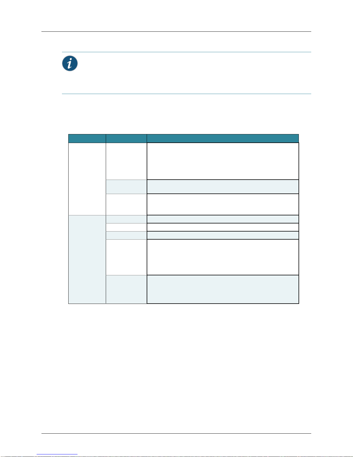
TAC Response Time
TAC responds to service requests as follows:
Contact method Priority Response time
Telephone Emergency One hour
Non-emergency Next business day
E-mail Non-emergency Next business day
Information Required When Requesting Service
To expedite your service request, please have the following information available when
you call or write to TAC for technical assistance:
Your company name and address
Your name, phone number, ce ll phone or pager number, and e-mail address
Name, model, and serial number of the product(s) requiring service
Software version(s) and release number(s)
Output of the show tech-support command
Wireless client information
License levels for RingMaster™ and Mobility Exchange™ (MX™) products
Description of any problems and status of any troubleshooting effort
Copyright © 2012, Juniper Networks, Inc. iii
Page 6

Warranty and Software Licenses
Current Juniper Networks warranty and software licenses are available at
http://www.juniper.net/.
Limited Warranty for Hardware and Software
TERMS AND CONDITIONS OF SALE
1. Software
Any software provided is licensed pursuant to the terms of Juniper Network’s
Software License Agreement, an electronic copy of which is provided with the
Software and a printed copy of which is available upon request. The terms and
conditions of the Software License Agreement are incorporated herein in its entirety
in this Terms and Conditions of Sale (“Terms and Conditions of Sale”) by this
reference. The terms of the Software License Agr eement control, except for the
limited warranty set forth below (“Limited Warranty”).
2. Limited Hardware Warranty
Juniper, Inc. (“Juniper” or “Juniper”) warrants to Customer, subject to the limitation
and disclaimer below, that all Juniper Networks hardware will be free from defect s in
material and workmanship under normal use as follows: (a) if the hardware was
purchased directly from Juniper Networks, for a period of one (1) year after original
shipment by Juniper Networks to Customer or (b) if the hardware was purchased
from a Juniper Networks Authorized Reseller, for a period of one (1) year from the
date of delivery to Customer, but in no event more than fifteen (15) months after the
original shipment date by Juniper Networks (“Limited Hardware Warranty”).
The date of original shipment from Juniper Networks will be determined by shipping
evidence on file at Juniper Networks. This Limited Hardware W arr anty extends only
to the Customer who was the original purchaser of the hardware and may not be
transferred to any subsequent repurchasing entity. During the Limited Hardware
Warranty period upon proper notice to Juniper Networks by Customer, Juniper
Networks will, at its sole option, either:
Repair and return of the defective hardware;
Replace the defective hardware with a new or refurbished component;
Replace the defective hardware with a different but similar component that
contains compatible features and functions; or
Refund the original purchase price upon presentation of proof of purchase to
Juniper Networks.
3. Restrictions on the Limited Hardware Warranty.
This Limited Warranty does not apply if hardware (a) is altered from its original
specifications, (b) is installed, configured, implemented or operated in any way that
is contrary to its documentation, (c) has damage resulting from negligence,
accident, or environmental stress, (d) was subject to unauthorized repair or
modification or (e) is provided to Customer for pre-production, evaluation or
charitable purposes.
4. Limited Software Warranty
Juniper Networks warrants to Customer, subject to the limitation and disclaimer
below, that the software will substantially conform to its published specifications as
follows: (a) if the software was purchased directly from Juniper Networks, for a
period of ninety (90) days after original shipment by Juniper Networks to Customer
or (b) if the software was purchased from a Juniper Networks Authorized Reseller,
for a period of ninety (90) days from the date of delivery to Customer commencing
not more than ninety (90) days after original shipment date by Juniper Networks),
(“Limited Hardware Warranty”) . The date of original shipment from Juniper Networks
iv Copyright © 2012, Juniper Networks, Inc.
Page 7

will be determined by shipping evidence on file at Juniper Networks. This Limited
Software Warranty extends only to the Customer of original purchaser of the
software and may not be transferred to any subsequent repurchasing entity.
During the Limited Software Warranty period upon proper notice to Juniper
Networks by Customer, Juniper Networks will, at its option, either:
Use reasonable commercial efforts to attempt to correct or provide workarounds
for errors;
Replace the software with functionally equivalent software; or
Refund to Customer the license fees paid by Customer for the software.
Juniper Networks does not warrant or represent that the software is error free or that
the software will operate without problems or disruptions. Additionally, and due to
the steady and ever-improving development of various attack and intrusion
technologies, Juniper does not warrant or repr esent that any networks, systems or
software provided by Juniper will be free of all possible methods of access, attack or
intrusion.
5. Restrictions on the Limited Software Warranty
This Limited Software Warranty does not apply if software (a) is altered in any way
from its specifications, (b) is installed, configured, implemented or operated in any
way that is contrary to its documentation, (c) has damag e resulting from negligence,
accident, or environmental stress, (d) was subject to unauthorized repair or
modification, or (e) is provided to Customer for pre-production, evaluation or
charitable purposes.
6. General Warranty Disclaimer
EXCEPT AS SPECIFIED IN THIS LIMITED WARRANTY, ALL EXPRESS OR
IMPLIED CONDITIONS, REPRESENTATIONS, AND WARRANTIES INCLUDING,
WITHOUT LIMITATION, ANY IMPLIED WARRANTY OR CONDITION OF
MERCHANTABILITY, FITNESS FOR A PARTICULAR APPLICATION OR
PURPOSE, NONINFRINGEMENT, SATISFACTORY QUALITY OR ARISING
FROM A COURSE OF DEALING, LAW, USAGE, OR TRADE PRACTICE, ARE
HEREBY EXCLUDED TO THE EXTENT ALLOWED BY APPLICABLE LAW. TO
THE EXTENT AN IMPLIED WARRANTY CANNOT BE EXCLUDED, SUCH
WARRANTY IS LIMITED IN DURATION TO THE AFOREMENTIONED
WARRANTY PERIOD. BECAUSE SOME STATES, COUNTRIES OR
JURISDICTIONS DO NOT ALLOW LIMITATIONS ON HOW LONG AN IMPLIED
WARRANTY LASTS, THE ABOVE LIMITATION MAY NOT APPLY. THIS LIMITED
WARRANTY GIVES YOU SPECIFIC LEGAL RIGHTS, AND YOU MAY ALSO
HA VE OTHER RIGHTS, WHICH V ARY FROM JURISDICTION TO JURISDICTION.
THE LIMITED WARRANTY ABOVE IS THE SOLE REMEDY FOR ANY BREACH
OF ANY WARRANTY WITH RESPECT TO THE HARDWARE AND SOFTWARE
AND IS IN LIEU OF ANY AND ALL OTHER REMEDIES.
7. Limitation of Liabilities
IN NO EVENT SHALL JUNIPER NETWORKS, ITS SUPPLIERS, OR ITS
AUTHORIZED RESELLERS BE LIABLE TO CUSTOMER OR ANY THRID PARTY
FOR ANY LOST REVENUE, PROFIT, OR DATA, OR FOR SPECIAL, INDIRECT,
CONSEQUENTIAL, INCIDENTAL, OR PUNITIVE DAMAGES REGARDLESS OF
HOW THOSE DAMAGES WERE CAUSED. NOR WILL JUNIPER NETWORKS,
ITS SUPPLIERS, OR ITS AUTHORIZED RESELLERS BE LIABLE FOR ANY
MONETARY OR PUNITIVE DAMAGES ARISING OUT OF THE USE OF, OR
INABILITY TO USE JUNIPER NETWORKS HARDWARE OR SOFTWARE.
JUNIPER NETWORK'S LIABILITY SHALL NOT EXCEED THE PRICE PAID BY
THE CUSTOMER FOR ANY HARDWARE OR SOFTWARE COVERED UNDER
THE TERMS AND CONDITIONS OF THIS WARRANTY. THIS LIMITATION OF
LIABILITY AND RESTRICTION ON DAMAGES APPLIES WHETHER IN
Copyright © 2012, Juniper Networks, Inc. v
Page 8

CONTRACT, TORT, NEGLIGENCE, OR OTHERWISE, AND SHALL APPLY EVEN
IF THE LIMITED WARRANTY F AILS OF ITS ESSENTIAL PURPOSE. W ARRANTY
LAWS VARY FROM JURISDICTION TO JURISDICTION, AND THE ABOVE
LIMITATIONS AND EXCLUSION OF CONSEQUENTIAL AND INCIDENTAL
DAMAGES MAY NOT APPLY TO YOU, DEPENDING UPON YOUR STATE,
COUNTRY OR JURISDICTION.
8. Procedures for Return of Hardware or Software under the Limited Warranty
Where repair or replacement is required under the Limited Warranty, Customer will
contact Juniper Networks and obtain a Return Materials Authorization number
(“RMA Number”) prior to returning any hardware and/or software, and will include
the Juniper Network’s RMA Number on all packaging. Juniper Networks will ship
repaired or replacement components within a commercially reasonable time after
receipt of any hardware and/or sof tware returne d for the Li mited Warranty purposes
to the address provided by Customer. Customer will pay freight and handling
charges for defective return to the address specified by Juniper Networks and
Juniper Networks will pay freight and handling charges for return of the repair or
replacement materials to Customer.
9. Miscellaneous
The Limited Warranty shall be governed by and construed in accordance with the
laws of the Sta te of California without reference to that State's conflict of laws rules
and as if the contract was wholly formed within the State of California. Customer
agrees that jurisdiction and venue shall be in Santa Clara County, California. Under
no circumstances shall the United Nations Convention on the International Sale of
Goods be considered for redress of grievances or adjudication of any warranty
disputes that include Juniper Networks hardware or software. If any provision of
these Terms and Conditions of Sale are held invalid, then the remainder of these
Terms and Conditions of Sale will continue in full force and effect. Where a
Customer has entered into a signed contractual agreement with Juniper Networks
for supply of hardware, software or services, the terms of that agreement shall
supersede any terms contained within this Limi ted W arranty. Customer understands
and acknowledges that the terms of this Limited Warranty, as well as material
information regarding the form, function, operation and limitations of Junip er
Networks hardware and software will change from time to time, and that the most
current revisions will be publicly available at the Juniper Networks corporate web
site (www.juniper.net).
vi Copyright © 2012, Juniper Networks, Inc.
Page 9

Ta b le of Co n te n t s
Chapter 1 WLA620, WLA622 and WLA632 Overview
Hardware Overview. . . . . . . . . . . . . . . . . . . . . . . . . . . . . . . . . . . . . . . . . . . . . . . . . . . . . . . . .1-1
WLA620 . . . . . . . . . . . . . . . . . . . . . . . . . . . . . . . . . . . . . . . . . . . . . . . . . . . . . . . . . . . . . . . . 1-1
WLA622 . . . . . . . . . . . . . . . . . . . . . . . . . . . . . . . . . . . . . . . . . . . . . . . . . . . . . . . . . . . . . . . . 1-1
WLA632 . . . . . . . . . . . . . . . . . . . . . . . . . . . . . . . . . . . . . . . . . . . . . . . . . . . . . . . . . . . . . . . . 1-2
Package Checklist . . . . . . . . . . . . . . . . . . . . . . . . . . . . . . . . . . . . . . . . . . . . . . . . . . . . . . . .1-2
External Hardware Features for the WLA620 . . . . . . . . . . . . . . . . . . . . . . . . . . . . . . . . . . . . . 1-3
External Antenna Options. . . . . . . . . . . . . . . . . . . . . . . . . . . . . . . . . . . . . . . . . . . . . . . . . . . 1-3
Ethernet Port. . . . . . . . . . . . . . . . . . . . . . . . . . . . . . . . . . . . . . . . . . . . . . . . . . . . . . . . . . . . . 1-4
Power Injector Module . . . . . . . . . . . . . . . . . . . . . . . . . . . . . . . . . . . . . . . . . . . . . . . . . . . . . 1-4
Receive Signal Strength Indicator (RSSI) BNC Connector. . . . . . . . . . . . . . . . . . . . . . . . . .1-5
Grounding Point . . . . . . . . . . . . . . . . . . . . . . . . . . . . . . . . . . . . . . . . . . . . . . . . . . . . . . . . . . 1-5
Wall- and Pole-Mounting Bracket Kits . . . . . . . . . . . . . . . . . . . . . . . . . . . . . . . . . . . . . . . . . 1-5
Lightning Protector for Outdoor Antenna . . . . . . . . . . . . . . . . . . . . . . . . . . . . . . . . . . . . . . . 1-5
System Configuration . . . . . . . . . . . . . . . . . . . . . . . . . . . . . . . . . . . . . . . . . . . . . . . . . . . . . . . 1-5
Features and Benefits . . . . . . . . . . . . . . . . . . . . . . . . . . . . . . . . . . . . . . . . . . . . . . . . . . . . . . . 1-6
External Hardware Features for the WLA622 . . . . . . . . . . . . . . . . . . . . . . . . . . . . . . . . . . . . . 1-7
LED Indicators . . . . . . . . . . . . . . . . . . . . . . . . . . . . . . . . . . . . . . . . . . . . . . . . . . . . . . . . . . . 1-8
External Antenna Options. . . . . . . . . . . . . . . . . . . . . . . . . . . . . . . . . . . . . . . . . . . . . . . . . . . 1-9
Ethernet Port. . . . . . . . . . . . . . . . . . . . . . . . . . . . . . . . . . . . . . . . . . . . . . . . . . . . . . . . . . . . . 1-9
Power Injector Module . . . . . . . . . . . . . . . . . . . . . . . . . . . . . . . . . . . . . . . . . . . . . . . . . . . . 1-10
Grounding Point . . . . . . . . . . . . . . . . . . . . . . . . . . . . . . . . . . . . . . . . . . . . . . . . . . . . . . . . .1-10
Water Tight Test Point . . . . . . . . . . . . . . . . . . . . . . . . . . . . . . . . . . . . . . . . . . . . . . . . . . . . 1-11
Wall- and Pole-Mounting Bracket Kits . . . . . . . . . . . . . . . . . . . . . . . . . . . . . . . . . . . . . . . . 1-11
Lightning Protector for Outdoor Antenna . . . . . . . . . . . . . . . . . . . . . . . . . . . . . . . . . . . . . . 1-11
System Configuration . . . . . . . . . . . . . . . . . . . . . . . . . . . . . . . . . . . . . . . . . . . . . . . . . . . . . .1-11
Features and Benefits . . . . . . . . . . . . . . . . . . . . . . . . . . . . . . . . . . . . . . . . . . . . . . . . . . . . . .1-11
External Hardware Features for the WLA632 . . . . . . . . . . . . . . . . . . . . . . . . . . . . . . . . . . . . 1-13
External Antenna Options. . . . . . . . . . . . . . . . . . . . . . . . . . . . . . . . . . . . . . . . . . . . . . . . . . 1-14
Multiple External Antenna Support. . . . . . . . . . . . . . . . . . . . . . . . . . . . . . . . . . . . . . . . . . . 1-15
High Power Mode . . . . . . . . . . . . . . . . . . . . . . . . . . . . . . . . . . . . . . . . . . . . . . . . . . . . . . . . 1-15
Ethernet . . . . . . . . . . . . . . . . . . . . . . . . . . . . . . . . . . . . . . . . . . . . . . . . . . . . . . . . . . . . . . .1-15
Features and Benefits . . . . . . . . . . . . . . . . . . . . . . . . . . . . . . . . . . . . . . . . . . . . . . . . . . . . . .1-16
Chapter 2 WLA Series Network Configurations
Infrastructure Configuration. . . . . . . . . . . . . . . . . . . . . . . . . . . . . . . . . . . . . . . . . . . . . . . . . . .2-1
WLAN Mesh Configuration . . . . . . . . . . . . . . . . . . . . . . . . . . . . . . . . . . . . . . . . . . . . . . . . . . . 2-2
Wireless Bridge Configuration. . . . . . . . . . . . . . . . . . . . . . . . . . . . . . . . . . . . . . . . . . . . . . . . . 2-3
i
Page 10

Table of Contents
Chapter 3 Installing and Connecting an Access Point
Installation Requirements and Recommendations . . . . . . . . . . . . . . . . . . . . . . . . . . . . . . . . . 3-1
RingMaster Network Plan and Work Orders. . . . . . . . . . . . . . . . . . . . . . . . . . . . . . . . . . . . .3-1
WLC Appliance Recommendation . . . . . . . . . . . . . . . . . . . . . . . . . . . . . . . . . . . . . . . . . . . . 3-1
Weather Conditions . . . . . . . . . . . . . . . . . . . . . . . . . . . . . . . . . . . . . . . . . . . . . . . . . . . . . . .3-1
Ethernet Cabling. . . . . . . . . . . . . . . . . . . . . . . . . . . . . . . . . . . . . . . . . . . . . . . . . . . . . . . . . . 3-2
Grounding. . . . . . . . . . . . . . . . . . . . . . . . . . . . . . . . . . . . . . . . . . . . . . . . . . . . . . . . . . . . . . . 3-2
WLA Radio Safety Advisories. . . . . . . . . . . . . . . . . . . . . . . . . . . . . . . . . . . . . . . . . . . . . . . . 3-3
Installing an WLA620. . . . . . . . . . . . . . . . . . . . . . . . . . . . . . . . . . . . . . . . . . . . . . . . . . . . . . . .3-3
Mounting the Unit . . . . . . . . . . . . . . . . . . . . . . . . . . . . . . . . . . . . . . . . . . . . . . . . . . . . . . . . . 3-3
Connecting External Antennas . . . . . . . . . . . . . . . . . . . . . . . . . . . . . . . . . . . . . . . . . . . . . . . 3-5
Connecting Cables to the Unit . . . . . . . . . . . . . . . . . . . . . . . . . . . . . . . . . . . . . . . . . . . . . . .3-7
Connecting the Outdoor Power Supply. . . . . . . . . . . . . . . . . . . . . . . . . . . . . . . . . . . . . . . . .3-7
Connecting a WLA to a WLC . . . . . . . . . . . . . . . . . . . . . . . . . . . . . . . . . . . . . . . . . . . . . . . . 3-7
Aligning Antennas for Bridge or Mesh Links. . . . . . . . . . . . . . . . . . . . . . . . . . . . . . . . . . . . . 3-8
Installing an WLA622. . . . . . . . . . . . . . . . . . . . . . . . . . . . . . . . . . . . . . . . . . . . . . . . . . . . . . .3-11
Mounting the Unit . . . . . . . . . . . . . . . . . . . . . . . . . . . . . . . . . . . . . . . . . . . . . . . . . . . . . . . .3-11
Connecting External Antennas . . . . . . . . . . . . . . . . . . . . . . . . . . . . . . . . . . . . . . . . . . . . . . 3-15
Connecting Cables to the Unit . . . . . . . . . . . . . . . . . . . . . . . . . . . . . . . . . . . . . . . . . . . . . .3-17
Connecting the Outdoor Power Supply. . . . . . . . . . . . . . . . . . . . . . . . . . . . . . . . . . . . . . . .3-18
Connecting the Power Injector . . . . . . . . . . . . . . . . . . . . . . . . . . . . . . . . . . . . . . . . . . . . . .3-18
Checking the LED Indicators . . . . . . . . . . . . . . . . . . . . . . . . . . . . . . . . . . . . . . . . . . . . . . . 3-19
Connecting a WLA to a WLC . . . . . . . . . . . . . . . . . . . . . . . . . . . . . . . . . . . . . . . . . . . . . . . 3-20
Aligning Antennas for Bridge or Mesh Links. . . . . . . . . . . . . . . . . . . . . . . . . . . . . . . . . . . . 3-22
Installing an WLA632. . . . . . . . . . . . . . . . . . . . . . . . . . . . . . . . . . . . . . . . . . . . . . . . . . . . . . .3-24
Mounting the Unit . . . . . . . . . . . . . . . . . . . . . . . . . . . . . . . . . . . . . . . . . . . . . . . . . . . . . . . .3-24
Connecting External Antennas . . . . . . . . . . . . . . . . . . . . . . . . . . . . . . . . . . . . . . . . . . . . . . 3-28
Multiple External Antenna Support . . . . . . . . . . . . . . . . . . . . . . . . . . . . . . . . . . . . . . . . . . . 3-29
High Power Mode . . . . . . . . . . . . . . . . . . . . . . . . . . . . . . . . . . . . . . . . . . . . . . . . . . . . . . . . 3-29
Ethernet . . . . . . . . . . . . . . . . . . . . . . . . . . . . . . . . . . . . . . . . . . . . . . . . . . . . . . . . . . . . . . .3-29
Connecting Cables to the Unit . . . . . . . . . . . . . . . . . . . . . . . . . . . . . . . . . . . . . . . . . . . . . .3-30
Connecting the Power Injector . . . . . . . . . . . . . . . . . . . . . . . . . . . . . . . . . . . . . . . . . . . . . .3-30
Connecting an WLA to an WLC . . . . . . . . . . . . . . . . . . . . . . . . . . . . . . . . . . . . . . . . . . . . . 3-32
Chapter 4 WLA Series Technical Specifications
Outdoor AP Mechanical and Compliance Specifications. . . . . . . . . . . . . . . . . . . . . . . . . . . . . 4-1
Federal Communication Commission Interference Statement . . . . . . . . . . . . . . . . . . . . . . . . 4-3
Industry Canada Statement. . . . . . . . . . . . . . . . . . . . . . . . . . . . . . . . . . . . . . . . . . . . . . . . . . . 4-4
MAC Addresses. . . . . . . . . . . . . . . . . . . . . . . . . . . . . . . . . . . . . . . . . . . . . . . . . . . . . . . . . . . .4-5
Antenna Specifications for WLA620 and WLA622. . . . . . . . . . . . . . . . . . . . . . . . . . . . . . . . . .4-5
8 dBi Omnidirectional (2.4 GHz). . . . . . . . . . . . . . . . . . . . . . . . . . . . . . . . . . . . . . . . . . . . . .4-5
8 dBi Omnidirectional (5 GHz) . . . . . . . . . . . . . . . . . . . . . . . . . . . . . . . . . . . . . . . . . . . . . . .4-6
13.5 dBi 120-Degree Sector . . . . . . . . . . . . . . . . . . . . . . . . . . . . . . . . . . . . . . . . . . . . . . . . . 4-7
10 dBi 120-Degree Sector . . . . . . . . . . . . . . . . . . . . . . . . . . . . . . . . . . . . . . . . . . . . . . . . . . 4-8
18 dBi 18-Degree Panel . . . . . . . . . . . . . . . . . . . . . . . . . . . . . . . . . . . . . . . . . . . . . . . . . . . .4-9
Signal Loss from Lightning Protector and Coaxial Cable . . . . . . . . . . . . . . . . . . . . . . . . . . .4-9
ii
Page 11

Antenna Specifications for WLA632 . . . . . . . . . . . . . . . . . . . . . . . . . . . . . . . . . . . . . . . . . . 4-10
High-Power Mode. . . . . . . . . . . . . . . . . . . . . . . . . . . . . . . . . . . . . . . . . . . . . . . . . . . . . . . . 4-11
Supported Antennas. . . . . . . . . . . . . . . . . . . . . . . . . . . . . . . . . . . . . . . . . . . . . . . . . . . . . . 4-12
WLA632 Mechanical and Compliance Specifications. . . . . . . . . . . . . . . . . . . . . . . . . . . . . 4-12
RSSI Meter Functionality . . . . . . . . . . . . . . . . . . . . . . . . . . . . . . . . . . . . . . . . . . . . . . . . . . 4-12
Chapter 5 Cables and Pinouts
Twisted-Pair Cable Assignments for the WLA620 and WLA622. . . . . . . . . . . . . . . . . . . . . . . 5-1
10/100BASE-TX Pin Assignments . . . . . . . . . . . . . . . . . . . . . . . . . . . . . . . . . . . . . . . . . . . . 5-1
Straight-Through Wiring . . . . . . . . . . . . . . . . . . . . . . . . . . . . . . . . . . . . . . . . . . . . . . . . . . . . 5-2
Crossover Wiring . . . . . . . . . . . . . . . . . . . . . . . . . . . . . . . . . . . . . . . . . . . . . . . . . . . . . . . . . 5-2
8-Pin DIN Connector Pinout for the WLA620 and WLA622. . . . . . . . . . . . . . . . . . . . . . . . . . . 5-3
8-Pin DIN to RJ-45 Cable Wiring . . . . . . . . . . . . . . . . . . . . . . . . . . . . . . . . . . . . . . . . . . . . . 5-3
WLA632 External Connectors . . . . . . . . . . . . . . . . . . . . . . . . . . . . . . . . . . . . . . . . . . . . . . . . . 5-4
Ethernet . . . . . . . . . . . . . . . . . . . . . . . . . . . . . . . . . . . . . . . . . . . . . . . . . . . . . . . . . . . . . . . .5-4
Chapter 6 Wireless Bridge Link Planning
Radio Path Planning . . . . . . . . . . . . . . . . . . . . . . . . . . . . . . . . . . . . . . . . . . . . . . . . . . . . . . . . 6-1
Antenna Height. . . . . . . . . . . . . . . . . . . . . . . . . . . . . . . . . . . . . . . . . . . . . . . . . . . . . . . . . . . 6-2
Radio Interference . . . . . . . . . . . . . . . . . . . . . . . . . . . . . . . . . . . . . . . . . . . . . . . . . . . . . . . .6-3
Weather Conditions . . . . . . . . . . . . . . . . . . . . . . . . . . . . . . . . . . . . . . . . . . . . . . . . . . . . . . .6-3
Ethernet Cabling. . . . . . . . . . . . . . . . . . . . . . . . . . . . . . . . . . . . . . . . . . . . . . . . . . . . . . . . . . 6-4
Grounding. . . . . . . . . . . . . . . . . . . . . . . . . . . . . . . . . . . . . . . . . . . . . . . . . . . . . . . . . . . . . . . 6-5
WLA622 Antenna Position and Orientation . . . . . . . . . . . . . . . . . . . . . . . . . . . . . . . . . . . . . 6-5
WLA Radio Safety Advisories. . . . . . . . . . . . . . . . . . . . . . . . . . . . . . . . . . . . . . . . . . . . . . . . 6-5
iii
Page 12

Table of Contents
iv
Page 13

WLA620, WLA622 and WLA632
Overview
A Juniper Networks model WLA620 provides IEEE 802.11 wireless access to the network.
WLAs are designed for use with a Juniper Networks WLAN controller. WLAs require
hardware installation only. All configuration for an WLA is performed on the WLC.
Warning: Installation must be performed by qualified service personnel only. Read and
follow all warning notices and instructions marked on the product or included in the
documentation. Before installing the product, read the Regulatory Guide document.
Informational Note: The WLA radios are disabled by default and can be enabled only by
a system administrator using the WLC.
Hardware Overview
WLA620
The WLA620 provides wireless access point services for clients in the local LAN ar ea,
and can provide point-to-point or point-to-multipoint wireless bridge links between
remote Ethernet LANs. The WLA is housed in a weatherproof enclosur e for mo untin g
outdoors and includes brackets for attaching to a wall, pole, radio mast, or tower
structure. The unit is powered through an Ethernet cable connection from a power
injector module installed indoors. The WLA620 provides a 54 Mbps half-duplex
connection for each active channel.
A wireless bridge system offers a solution for connectivity between remote Ethernet
wired LANs, or to provide Internet access to an isolated site where a wired link may be
difficult or expensive to deploy. The wireless bridge connection provides data rates of
up to 108 Mbps.
Radio Characteristics – The IEEE 802.11a and 802.11g standards use a radio
modulation technique known as Orthogonal Frequency Division Multiplexing (OFDM),
and a shared collision domain (CSMA/CA). The 802.11a standard operates in the 5
GHz Unlicensed National Information Inf ra str uc tu re (UNII ) ba nd , an d th e 80 2. 11g
standard in the 2.4 GHz band.
IEEE 802.11g includes backward compatibility with the IEEE 802.11b standard. IEEE
802.11b also operates at 2.4 GHz, but uses Direct Sequence Spread Spectrum
(DSSS) and Complementary Code Keying (CCK) modulation technology to achieve a
communication rate of up to 11 Mbps.
Copyright © 2012, Juniper Networks, Inc. 1
Page 14

WLA620, WLA622 and WLA632 Overview
WLA622
The WLA622 provides only external antenna options and is designed to operate as the
“root bridge” in point-to-multipoint configurations, supporting wireless bridge
connections to as many as six units. The WLA is housed in a weatherproof enclosure
for mounting outdoors and includes brackets for att aching to a wall, pole, radi o mast, or
tower structure. The wireless bridge connection provides data rates of up to 54 Mbps. A
WLC cannot be used to power the outdoor WLA. The WLA requires a Juniper-designed
XPS power supply for proper operation.
WLA632
The WLA632 is a 802.11a/b/g/n WLA that is designed for pole-mounting and wall
mounting. The WLA632 supports 6 antenna ports, 3 for the 11a/n radio and 3 for the
11b/g/ n ra dio . A nt en na s ot he r than Juniper approved antennas are not supported. The
WLA632 does not support internal antennas or PoE. A WLC cannot be used to power
this WLA. A WLA-XPS9001GO power supply that uses the IP67 multi-pin DIN
connector is required. The WLA-XPS9001GO is specifically designed for the WLA632
and is available from Juniper Networks.
WLA-XPS9001GO Power Supply Unit
The WLA-XPS9001GO PSU has separate SKUs for North American and International
users.
WLA-XPS9001GO-NA— An outdoor 802.3at compliant, 100-240 VAC 50-60Hz input,
Gigabit PoE midspan PSU with a North American connector that ships with the
mounting bracket. This PSU and NA connector is intended for u se in countries following
North America Safety Standards.
WLA-XPS9001GO-INTL— An outdoor 802.3at compliant, 100-240 VAC 50-60Hz input,
Gigabit PoE midspan PSU with a International power cord. This PSU and international
power cord is intended for use in world-wide opera tio ns except countries following
North America Safety Standards.
Warning: The WLA632 must only be used with a Juniper Networks approved
WLA-XPS9001GO power supply in order to prevent possible damage to the unit. The
WLA-XPS9001GO power supply is intended for indoor and outdoor environments.
Package Checklist
The WLA620 package includes:
1 WLA620
1 Category 5 network cable, length 50 m (164 ft)
1 power injector module and power cord
Outdoor pole-mounting bracket kit
Installation manual
Optional: 2 N-type RF coaxial cables
Optional: Outdoor wall-mounting bracket kit
Optional: Lightning protector for outdoor antenna
The WLA622 package includes:
1 WLA622
WLA-XPS9001GO (packaged in a separate box)
2 Copyright © 2012, Juniper Networks, Inc.
Page 15
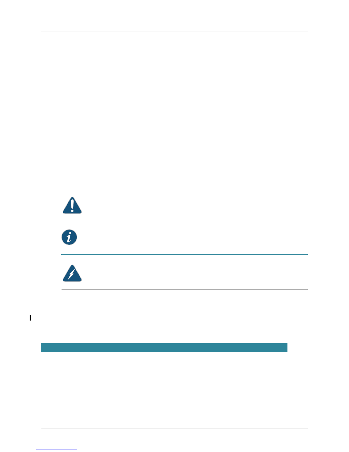
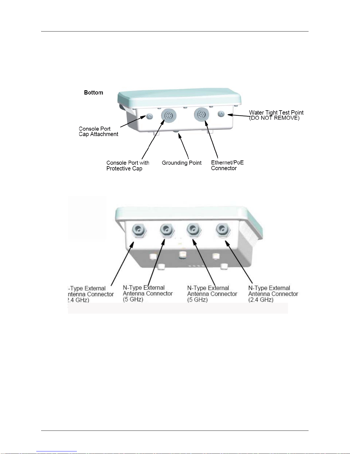
WLA620, WLA622 and WLA632 Overview
Ethernet Port
RSSI Connector
with Protective Cap
Grounding Point Screw
Installation manual
Optional: Lightning protector for outdoor antenna
The WLA632 package includes:
1 WLA632
Mounting brackets, split washers and mounting hardware
Weather sealing caps for all 6 external antenna connectors
Installation manual
1 WLA-XPS9001GO outdoor power supply.
Circular DIN to RJ45 dongle cable and waterproof caps for RJ45 dongle
Two-hole tabular lug for AWG #8 ground cable
Antenna connector terminator. Any unused antenna connector on an active radio
must be terminated.
Contact Juniper Networks if there are any incorrect, missing or damaged parts. If
possible, retain the carton, including the original packing materials. Use them again to
repack the product in case there is a need to return it.
External Hardware Features for the WLA620
Figure 1–1 and Figure 1–2 below show the external hardware features of the WLA620.
Figure 1–1. WLA Model WLA620—Bottom View
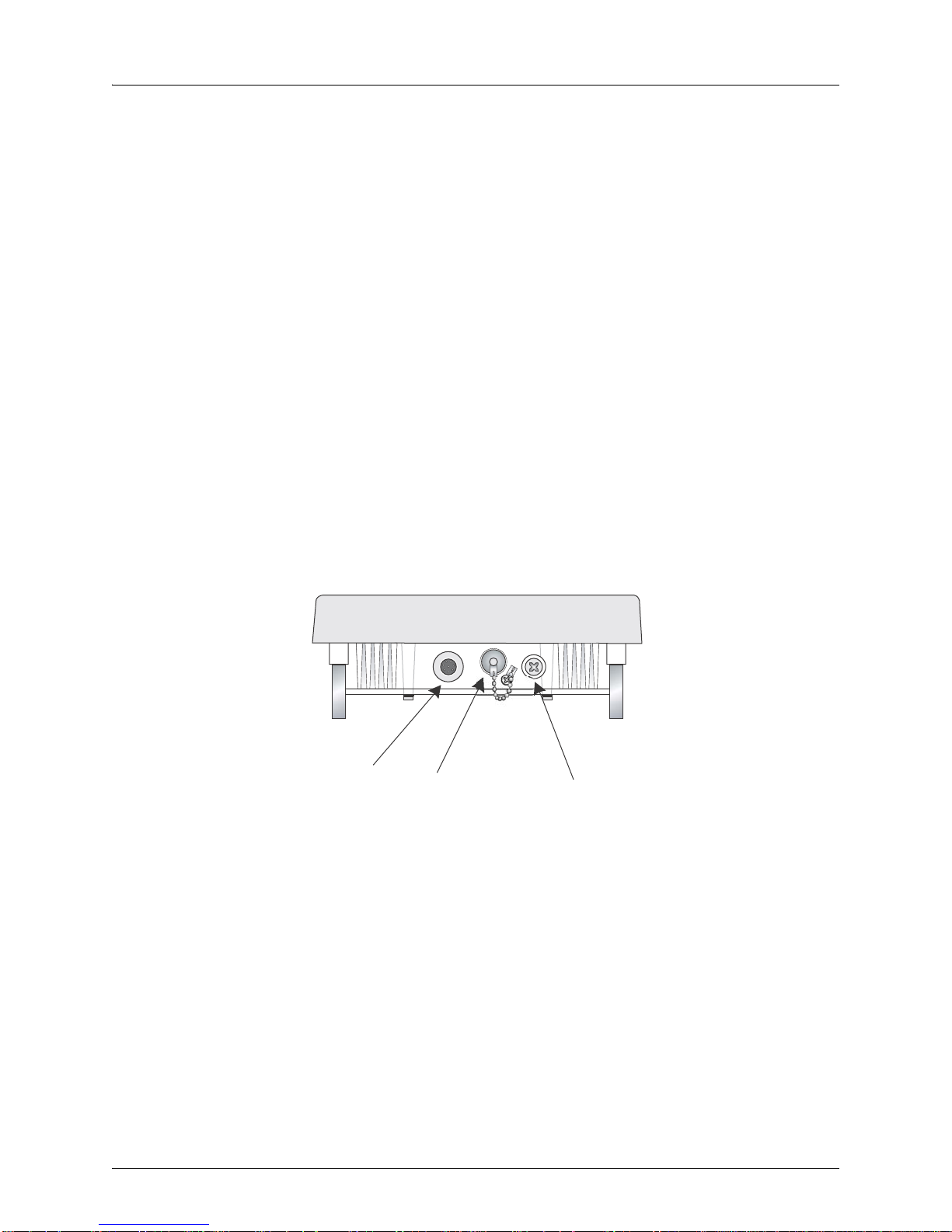
Figure 1–2. WLA Model WLA620—Top View
Copyright © 2012, Juniper Networks, Inc. 3
Page 16
WLA620, WLA622 and WLA632 Overview
N-Type External
Antenna Connector
(2.4 GHz)
N-Type External
Antenna Connector
(5 GHz)
External Antenna Options
The WLA620 unit does not include an integra ted antenna, but provides various external
antenna options for both 5 GHz and 2.4 GHz operation. The WLA620 unit requires the
2.4 GHz 8 dBi omnidirectional external antenna for 2.4 GHz operation. The following
table summarizes the external antenna options:
Table 1: External Antenna Options
HPBW*
Antenna Type Gain (dBi)
5 GHz Omnidirectional 8 360 12 Linear, vertical
5 GHz 120-Degree Sector 13.5 120 6 Linear, vertical
5 GHz 18-Degree Panel 18 18 18 Linear, vertical
2.4 GHz 120-Degree Sector 10 120 15 Linear, vertical
2.4 GHz Omnidirectional 8 360 15 Linear, vertical
* Half-power beam width in degrees
Horizontal
HPBW*
Ver ti ca l
Polarization
External antennas connect to the N-type RF connectors on the WLA620 using the
provided coaxial cables.
Ethernet Port
The WLA620 has one 10BASE-T/100BASE-TX 8-pin DIN port that connects to the
power injector module using the included Ethernet cable. The Ethernet port connection
provides power to the WLA620 as well as a data link to the local network.
Informational Note: The power injector module does not support Power over Ethernet
(PoE) based on the IEEE 802.3af standard. The WLA620 must always be powered on by
being connected to the power injector module.
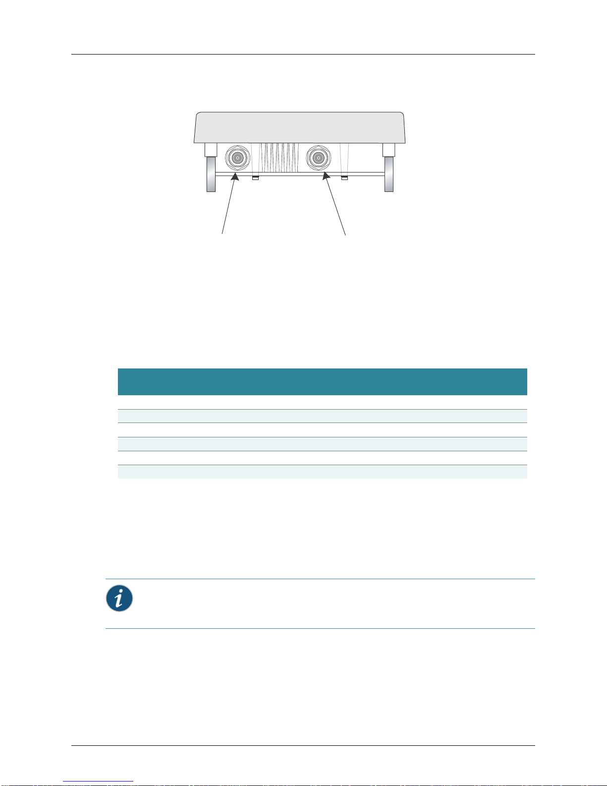
Power Injector Module
The WLA620 receives power through the network cable connection using
power-over-Ethernet technology. A power injector module is included in the WLA620
package and provides two RJ45 Ethernet ports, one for connec tin g to th e WLA620
(Output), and the other for connecting to a WLC switch or a local LAN switch (Input).
4 Copyright © 2012, Juniper Networks, Inc.
Page 17
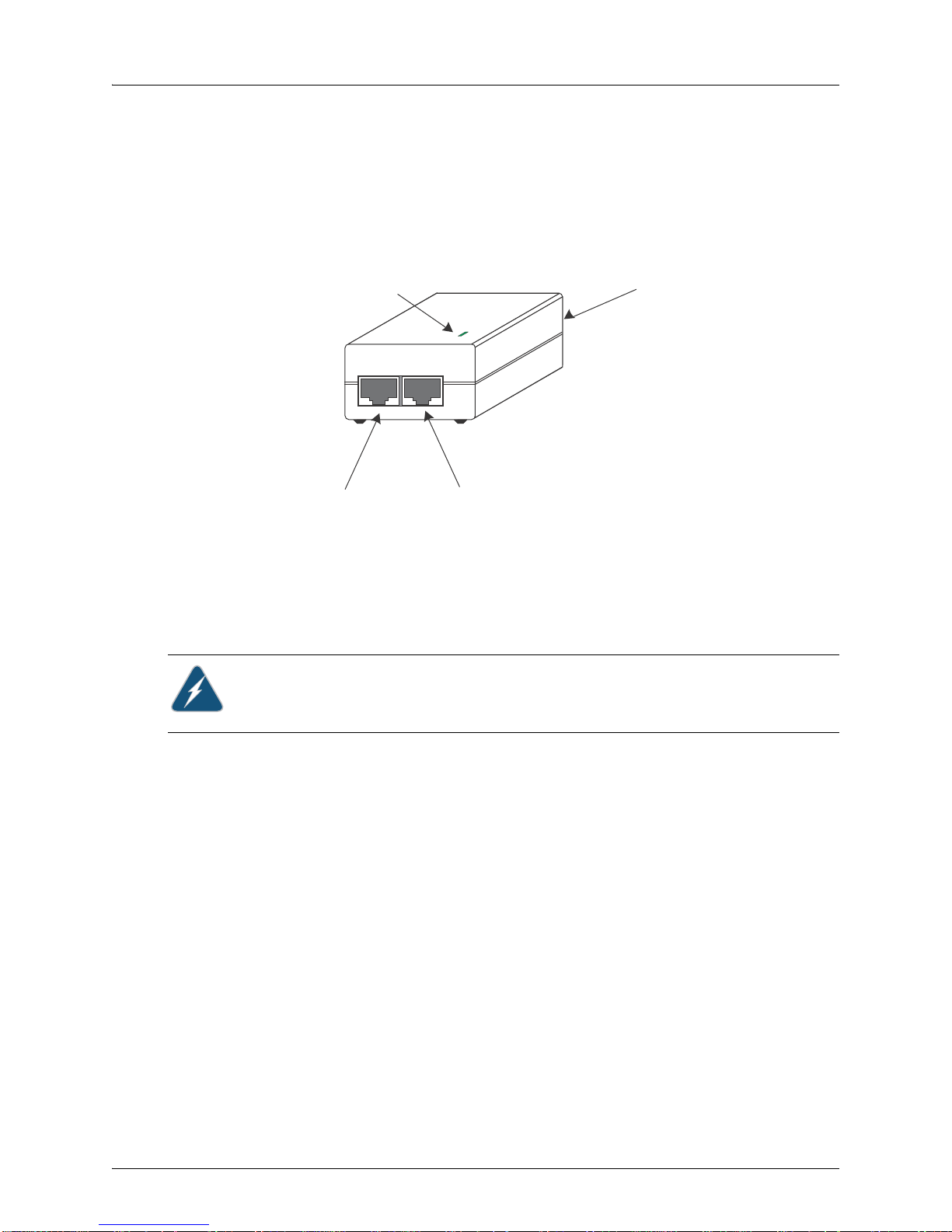
WLA620, WLA622 and WLA632 Overview
Input Output
LED Indicator
Ethernet from
Local Network
Ethernet and Power
to MP-620
AC Power Socket
(Hidden)
The Input port uses an MDI (i.e., internal straight-through) pin configuration. You can
therefore use straight-through twisted-pair cable to connect this port to most network
interconnection devices such as a switch or router that provide MDI-X ports. However,
when connecting the access point to a workstation or other device without MDI-X ports,
you must use crossover twisted-pair cable.
Figure 1–3. Power Injector Module
The WLA620 does not have a power switch. It is powered on when the Ethernet port is
connected to the power injector module, and the power injector module is connected to
an AC power source. The power injector includes one LED indicator tha t turns on when
AC power is applied.
The power injector module automatically adjusts to any AC voltage between 100-240
volts at 50 or 60 Hz. No voltage range settings are required.
Warning: The power injector module is designed for indoor use only. Never mount the
power injector outside with WLA620 unit.
Receive Signal Strength Indicator (RSSI) BNC Connector
The RSSI connector provides an output voltage that is proportio nal to the received radio
signal strength. A DC voltmeter can be connected the this port to assist in aligning the
antennas at both ends of a wireless bridge link.
Grounding Point
Even though the WLA620 includes a built-in lightning protection, it is important that the
unit is properly connected to ground. A grounding screw is provided for attaching a
ground wire to the unit.
Wall- and Pole-Mounting Bracket Kits
The WLA620 includes bracket kits that can be used to mount the unit to a wall, pole,
radio mast, or part of a tower structure.
Lightning Protector for Outdoor Antenna
Copyright © 2012, Juniper Networks, Inc. 5
If you are using the WLA620 with an outdoor antenna, Juniper Networks recommends
installing an external lightning protector for the antenna. An external lightning protector
may be obtained from Juniper Networks.
Page 18
WLA620, WLA622 and WLA632 Overview
Indoor Outdoor
LAN Switch
AC Power
Power
Injector
WLA620 Unit
GroundWire
EthernetCable EthernetCable
E xternal A ntenna
RF C oaxial Cable
Lightning
Protector
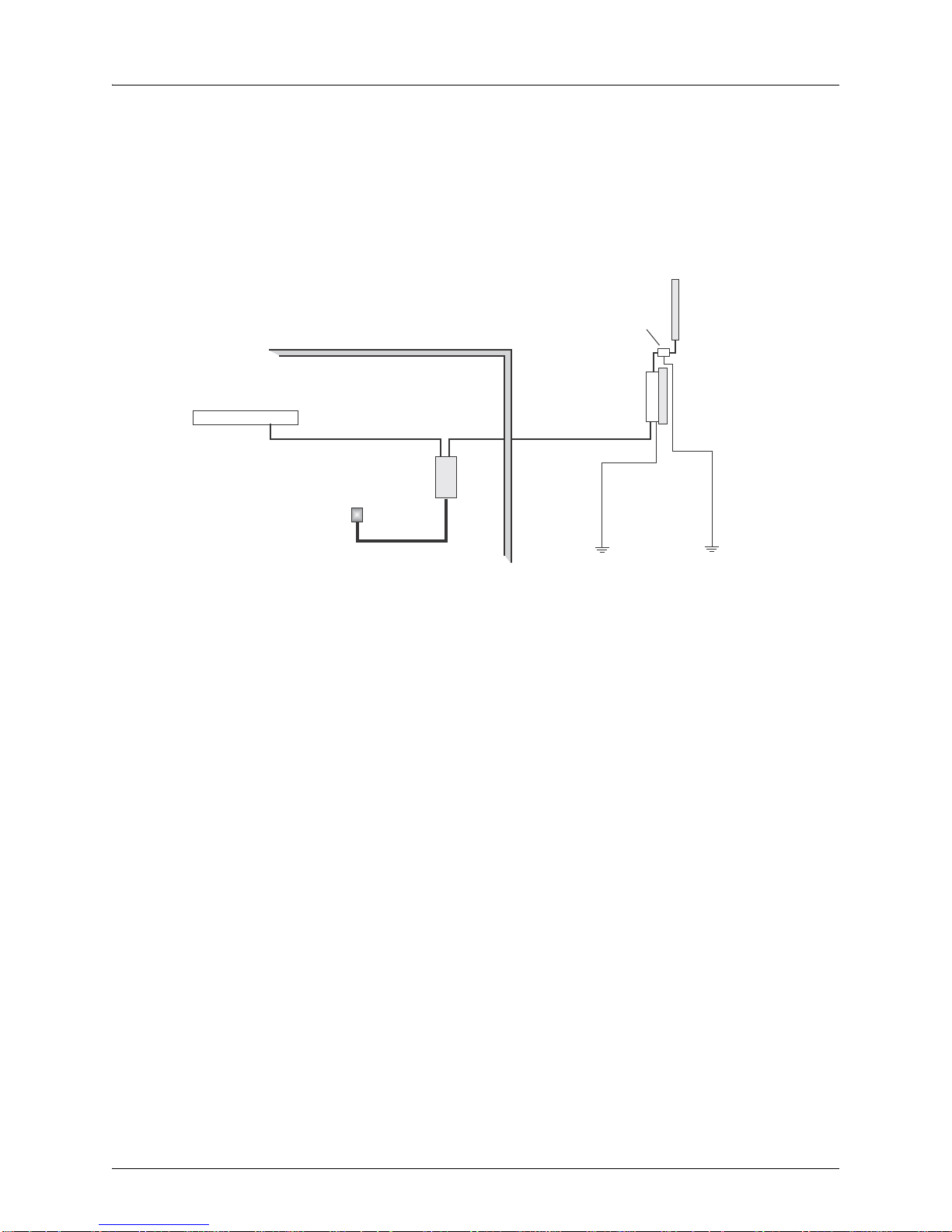
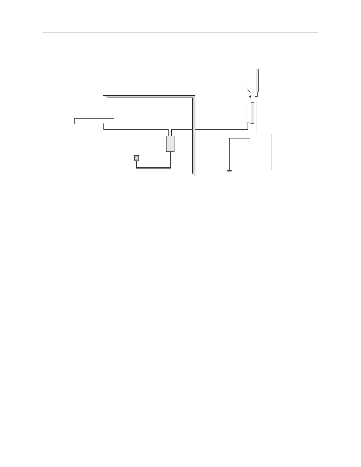
System Configuration
At each location where an WLA620 unit is installed, it must be connected to the local
network using the power injector module. The following figure illustrates the system
component connections.
Features and Benefits
The WLA620 provides the following features and benefits:
The WLA620 supports access point services for the 5 GHz and 2.4 GHz radios using
various external antenna options
Maximum data rate up to 108 Mbps on the 802.11a (5 GHz) radio
Outdoor weatherproof design
IEEE 802.11a and 802.11b/g compliant
Local network connection via 10/100 Mbps Ethernet port
Powered through its Ethernet cable connection to the powe r inje cto r m odule
Includes wall- and pole-mount brackets
Security through 64/128/152-bit Wired Equivalent Protection (WEP) or 128-bit
Advanced Encryption Standard (AES) encryption
Scans all available channels and selects the b est channel and data rate based on the
signal-to-noise ratio
Figure 1–4. System Component Connections
6 Copyright © 2012, Juniper Networks, Inc.
Page 19
WLA620, WLA622 and WLA632 Overview
Port 1
Port 2
Port 3 Port 4
External Hardware Features for the WLA622
Figure 1–5. MP Access Point Model WLA622—Bottom View
Figure 1–6. Access Point Model WLA622—Top View. Antenna ports are numbered
from the left 1 to 4.
Copyright © 2012, Juniper Networks, Inc. 7
Page 20
WLA620, WLA622 and WLA632 Overview
Power
Link
11a
11b/g
Power
802.11a Wireless
Link/Activity
Ethernet
Link/Activity
802.11b/g Wireless
Link/Activity
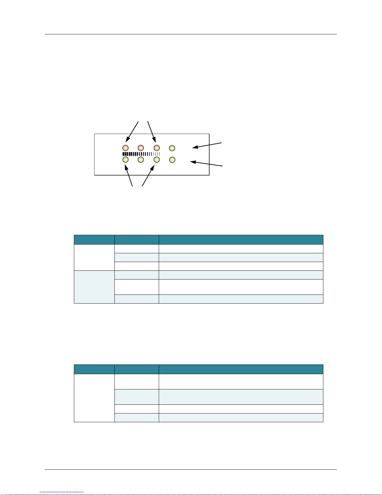
LED Indicators
The LEDs are used for RSSI signal strength measurements to aim directional antennas
and to indicate the state of the WLA. The access point includes eight status LED
indicators, as shown below . The LEDs are viewed right to le f t as you look a t the ba ck of
the WLA.
The table below describes the system status LEDs.
Table 2: External Antenna Options
LED Status Description
Power Green Indicates that the system is working normally.
Amber Indicates a system reset.
Off The bridge is not receiving power or there is a fault with the power supply.
Link Green Indicates a valid 10/100 Mbps Ethernet cable link with no activity.
Flashing Green Indicates that the access point is transmitting or receiving data on a
10/100 Mbps Ethernet LAN. Flashing rate is proportional to network activity.
Off No link is present or the Ethernet LAN port is disabled.
The 1 1 a and 11b/g LEDs operate in two display modes, which are configurable through
the management interface. The RSSI mode is for aligning antennas in a b ridge link. The
WLA mode is for indicating data traffic rates.
The table below describes the wireless status LEDs in WLA mode.
Table 3: Wireless Status LEDs in WLA Mode
LED Status Description
11a (three LEDs) Slow Flashing
Green
Fast Flashing
Green
Green Indicates a high level of network activity.
Off No signal detected or the 802.11a radio is disabled.
The 802.11a radio is enabled with a low level of network activity.
Indicates a medium level of network activity.
8 Copyright © 2012, Juniper Networks, Inc.
Page 21
Table 3: Wireless Status LEDs in WLA Mode
LED Status Description
11b/g
(three LEDs)
Slow Flashing
Amber
Fast Flashing
Amber
Off No signal detected or the 802.11b/g radio is disabled.
The 802.11b/g radio is enabled with a low level of network activity.
Indicates a medium level of network activity.
The table below describes the wireless status LEDs in RSSI mode.
Table 4: Wireless Status LEDs in RSSI Mode
LED Status Description
11a
(three LEDs)
11b/g
(three LEDs)
Off No signal detected or the 802.11a radio is disabled.
Slow Flashing
Green
Fast Flashing
Green
On Green Indicates a high level signal.
Off No signal detected or the 802.11b/g radio is disabled.
Slow Flashing
Green
Fast Flashing
Green
The 802.11a radio is enabled with a low level signal.
Indicates a medium level signal.
The 802.11b/g radio is enabled with a low level signal.
Indicates a medium level signal.
WLA620, WLA622 and WLA632 Overview
External Antenna Options
The WLA622 supports one or two antennas per radio. If there are two antennas
connected to the radio then antenna diversity is used to send all traffic types. If there is
one antenna then proper operations of antenna diversity may be affected.
By default there is one external antenna so there will be no use of antenna diversity for
WLAs with external antennas defined. The setting below is applied per radio so you can
have one radio indoors and one radio outdoors.
set ap num radio num external-antennas num
Informational Note: This is a new command, and it is only supported in MSS 7.1 or higher.
Caution: The splitting of antennas on a single radio between indoors and outdoors is not
allowed.
The WLA622 supports one or two antennas per radio. If there are two antennas they
must be the same antenna model. A single antenna will always be connected to the
connector 1 for 2.4 GHz and connector 3 for 5Ghz.
Copyright © 2012, Juniper Networks, Inc. 9
Page 22

WLA620, WLA622 and WLA632 Overview
The WLA622 supports four antenna ports, two for the 11a radio and two for the 11bg
radio. The supported antennas models are:
802.11bg Radio
ANT-1120-OUT
ANT-1360-OUT
802.11a Radio
ANT-5120-OUT
ANT-5360-OUT
ANT-5PNL-OUT (for single antenna only for use on port 3)
External antennas connect to the N-type RF connectors on the wireless bridg e either
directly or using coaxial cables.
Ethernet Port
The wireless bridge has one 10BASE-T/100BASE-TX 8-pin DIN port that connects to
the power injector module using the included Ethernet cable. The Ethernet port
connection provides power to the wireless bridge as well as a data link to the local
network.
The wireless bridge appears as an Ethernet node and performs a bridging function by
moving packets from the wired LAN to the remote end of the wireless bridge link.
Informational Note: The power injector module does not support Power over Ethernet
(PoE) based on the IEEE 802.3af standard. The wireless bridge unit must always be
powered on by being connected to the power injector module.
Power Injector Module
The WLA622 receives power through the network cable connection using
Power-over-Ethernet (PoE) technology. An outdoor power injector module is available
seperately and provides two RJ45 Etherne t ports, one for conn ecting to the WLA622
(PoE Output), and the other for connecting to an WLC or a local LAN switch Data
(Input).
The Input port uses an MDI (i.e., internal straight-through) pin configuration. You can
therefore use straight-through twisted-pair cable to connect this port to most network
interconnection devices such as a switch or router that provide MDI-X ports. However,
when connecting the access point to a workstation or other device without MDI-X ports,
you must use crossover twisted-pair cable.
10 Copyright © 2012, Juniper Networks, Inc.
Page 23
WLA620, WLA622 and WLA632 Overview
Ground Wire
Ethernet Cabl e
To MP-622
Figure 1–7. Power Injector Module
The WLA622 does not have a power switch. It is powered on when the Ethernet port is
connected to the power injector module, and the power injector module is connected to
an AC power source.
The power injector module automatically adjusts to any AC voltage between 100-240
volts at 50 or 60 Hz. No voltage range settings are required.
Caution: The power injector module is designed for indoor use.
Grounding Point
In order for the WLA622 includes a built-in lightning protector to work properly, the unit
must be properly connected to ground. A grounding screw is provided for attaching a
ground wire to the unit.
Water Tight Test Point
Caution: Do not remove or loosen this screw. If you do, you can damage the unit.
Wall- and Pole-Mounting Bracket Kits
The WLA622 includes bracket kits that can be used to mount the unit to a wall, pole,
radio mast, or part of a tower structure.
Lightning Protector for Outdoor Antenna
If you are using the WLA622 with an outdoor antenna, Juniper Networks strongly
recommends installing an external lightning protector for the antenna. An external
lightning protector may be obtained from Juniper Networks.
System Configuration
At each location where an WLA622 unit is installed, it must be connected to the local
network using the power injector module. The following figure illustrates the system
component connections.
Copyright © 2012, Juniper Networks, Inc. 11
Page 24
WLA620, WLA622 and WLA632 Overview
LAN Switch
Indoor Out
door
AC Power
Power
Injector
WLA622 Unit
Ground Wire
Ethernet Cable Ethernet Cable
External Antenna
RF Coaxial Cable
Lightning
Protector
Figure 1–8. System Component Connections
Features and Benefits
The WLA622 provides the following features and benefits:
The WLA622 supports access point services for the 5 GHz and 2.4 GHz radios using
various external antenna options
WLA622 units support 5 GHz point-to-multipoint links using various external
Juniper-supplied antenna options
Maximum data rate up to 54 Mbps on the 802 .11a (5 GHz) radio
Outdoor weatherproof design
IEEE 802.11a and 802.11b/g compliant
Local network connection via 10/100 Mbps Ethernet port
Powered through its Ethernet cable connection to the powe r inje cto r m odule
Includes wall- and pole-mount brackets
Security through 64/128/152-bit Wired Equivalent Protection (WEP) or 128-bit
Advanced Encryption Standard (AES) encryption
Scans all available channels and selects the b est channel and data rate based on the
signal-to-noise ratio.
Manageable through an easy-to-use web-browser interface, command line (via Telnet),
or SNMP network management tool.
12 Copyright © 2012, Juniper Networks, Inc.
Page 25
WLA620, WLA622 and WLA632 Overview
2.4GHz
Antenna Ports
LEDs
5GHz
Antenna Ports
Power
Ethernet Port
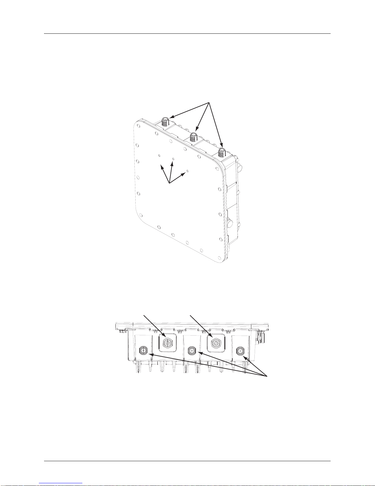
External Hardware Features for the WLA632
Copyright © 2012, Juniper Networks, Inc. 13
Page 26
WLA620, WLA622 and WLA632 Overview
Informational Note: Two separate cables are required for power and ethernet function
on the WLA632. Both the cable dongles are RJ45 on one end, but one cable is specific to
power and one is specific to data. If the RJ45 cable ends are swapped, the unit will not
power up but will not be damaged. If the RJ45 cable ends are correctly inserted, the unit
will function normally.
LED Indicators
The WLA632 has LEDs that provide status information for the device. The table below
lists the function of the LEDs.
Table 5: WLA632 LED Functions
LED Status Description
Health Solid green All the following are true:
Solid amber WLA is waiting to receive boot instructions and a configuration file from an
Alternating green
and amber
Radio 1 /Radio 2 Solid green A client is associated with the radio.
Blinking green Associated client is sending or receiving traffic.
Blinking amber Non-associated client is sending or receiving traffic.
Alternating green
and amber
Unlit Means one of the following:
Management link with an WLC is operational.
WLA has booted.
WLA has received a valid configuration from an WLC.
At least one radio is enabled or is in sentry mode.
WLC.
WLA is booting and receiving a configuration file from an WLC.
After the MP boots and receives a configuration, this LED appearance
persists until a radio is enabled or is placed in sentry mode.
Radio is unable to transmit. This state can occur due to any of the following:
Excessive radio interference in the environment is preventing the radio
from sending beacons.
DFS has detected radar and is restricting traffic.
The radio has failed.
Radio is disabled and active scan is enabled. (The radio is in sentry
mode.)
Radio is enabled, but no clients are associated with it.
External Antenna Options
The WLA632 supports six antenna ports, 3 for the 11a/n radio and 3 for the 11b/g/n
radio. The 3 802.11 b/g/n antenna ports are on the top of the WL A an d a re nu mbe re d 1
to 3 from left to right. The 3 802.11a/b/g/n antenna ports are on the bottom of the WLA
with the ethernet and power ports. The antenna ports are numbered 4 to 6 from left to
right with port 4 on the outside edge of the RJ45 ethernet port.
The supported antennas models are:
802.11bgn Radio
ANT-7360A-OUT (N-type female connector)
ANT-77555-OUT (3 RPSMA- male connector)
ANT-74520-OUT (3 RPSMA- male connector)
14 Copyright © 2012, Juniper Networks, Inc.
Page 27
WLA620, WLA622 and WLA632 Overview
802.11an Radio
ANT-7360A-OUT (N-type female connector)
ANT-74520-OUT (3 RPSMA- male connector)
ANT-77555-OUT (3 RPSMA- male connector)
ANT-5007-OUT (2-N-type connector)
The port usage depends on the antennas in use. If the OMNI antennas are used there
must be 3 antennas installed for the radio. If the ANT-5007-OUT antenna is used then
the two edge ports must be connected to the antenna (ports 4 and 6). The middle port
will be turned off by the software and should be terminated. If either the ANT-77555 or
74520 are used all three connectors must be connected to the WLA for the correct
radio. (A RPSMA N-type adaptor is required.)
set ap apnum radio num antennatype {ANT-7360A-OUT | ANT 77555-OUT | ANT
74520-OUT | ANT-5007-OUT} …
The antenna-location must be either indoors or outdoors. Although this is an outdoor
WLA it may be used indoors.
set ap apnum radio # antenna-location {indoors | outdoors}
Informational Note: Splitting the antennas between indoors and outdoors on the same
radio band is not allowed.
Multiple External Antenna Support
The WLA632 supports the use of multiple antenna ports per radio. Since there are
always multiple antennas connected, antenna diversity is always on. The command to
set the number of external antennas does not apply to the WLA632. The number of
antenna ports in use is determined by the antenna type.
set ap num radio num external-antennas num
If the ANT-5007-OUT antenna is in use on the 11a/n radio then the radio configuration
will revert to 2 x 3 mode rather than 3 x 3 mode and the middle port for the radio must
not be used.
Ethernet
The WLA632 supports a single IEEE 802.3-compliant auto-sensing 10/100/1000 BaseT
Ethernet interface on the Ethernet input connector. The WLA is configured as auto
MDI/MDIX. The WLA632 is powered from the WLA-XPS9001GO power supplies.
Caution: The WLA622 and WLA632 must only be used with a Juniper
Networks-approved WLA-XPS9001GO outdoor power supply in order to prevent possible
damage to the unit.
Caution: The 10/100 data port on the XPS is not used.
Copyright © 2012, Juniper Networks, Inc. 15
Page 28
WLA620, WLA622 and WLA632 Overview
Caution: If you convert the 8 pin female circular DIN data port on the WLA632 bulkhead
to a standard RJ45 waterproof connection for the 10/100/1000 data port, PoE on the
10/100/1000 port must be disabled to prevent service interruption.The WLA632 does not
support PoE on the 10/100/1000 Ethernet data port.
Caution: Always add the waterproof cap to the RJ45 cable when installing the DIN-RJ45
dongle. Water can cause damage to the unit and the cables.
The WLA632 48VDC / Ethernet inputs provides primary and secondary lightning
protection up to 4KV on all conductors.
The Ethernet interface supports a cable length of up to 100m over CAT5e or CAT6
cable.
Grounding Point
Caution: Always ground the unit first with an appropriate grounding wire (not included)
by attaching it to the grounding screw on the unit.
The WLA632 has a two-hole grounding boss with threaded screws and washers for
direct electrical connection to earth ground. The two-hole tubular lug can be crimped
(standard crimp tool is required) on a AWG #8 copper wire for grounding.
Water Tight Test Point
Caution: Do not remove or loosen the pressure balance plug on the side of the unit. If you
do, you can damage the unit.
Wall- and Pole-Mounting Bracket Kits
The WLA632 includes bracket kits that can be used to mount the unit to a wall, pole,
radio mast, or part of a tower structure.
Lightning Protector for Outdoor Antenna
If you are using the WLA632 with an outdoor antenna, Juniper Networks strongly
recommends installing an external lightning protector for the antenna. An external
lightning protector may be obtained from Juniper Networks.
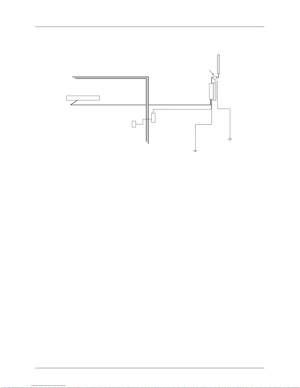
System Configuration
At each location where an WLA632 unit is installed, it must be connected to the local
network but the power injector is not required. The following figure illustrates the system
component connections.
16 Copyright © 2012, Juniper Networks, Inc.
Page 29
WLA620, WLA622 and WLA632 Overview
LAN Switch
Indoor
Outdoor
WLA632
Ethernet Cable Ethernet Cable
External Antenna
RF Coaxial Cable
Lightning
Protector
Ground Wire
WLA-XPS9001GO
CAT-5 cabling
with appropriate
adapters
AC Power Outlet
Figure 1–9. System Component Connections
Features and Benefits
The WLA632 provides the following features and benefits:
802.11 a/b/g/n Features
High performance 11 Mbps (802.11b) or 54Mbps (802.11a/g) or 300Mbps(802.11n)
data rate
Wi-Fi, WPA interoperability ready
WPA/WPA2 with PSK/802.1x with TKIP/AES
40-bit and 128-bit WEP
Seamless roaming within the IEEE 802.11 a/b/g/n WLAN infrastructure.
Adjustable output power support
Interoperability with Juniper Networks Wireless Security Switch
Auto-sensing 10/100/1000 Ethernet port with auto MDI/MDI-X but has no PoE
support on the 10/100/100 (data) port
Comply with IEEE 802.3, 802.3u and 802.3ab
Powered by 30W/48Vdc outdoor AC/DC power supply.
Copyright © 2012, Juniper Networks, Inc. 17
Page 30

WLA620, WLA622 and WLA632 Overview
18 Copyright © 2012, Juniper Networks, Inc.
Page 31

WLA Series Network Configurations
Client
Backbone
MX-216
WLC
Campus Building
This chapter illustrates network configurations supported for the Juniper Networks
WLAs.
Infrastructure Configuration
In an infrastructure topology , th e WLA620, WLA622, and WLA632 provide access to a
wired LAN for 802.11a/b/g wireless workstations (802.11 a/b/g/n with WLA632 only).
The WLA620, WLA622 and WLA632 have weatherproof casing and can be installed
outdoors (for example, on a pole) to provide network access to clients located outside.
Figure 2–1. Infrastructure Topology with Outdoor WLA
The WLA620, WLA622, and WLA632 can be connected directly to an WLC or
indirectly over the network. Power must be available at the location where the
WLA620, WLA622, or WLA632 is installed.
Informational Note: UL CMX-rated or better cables should always be used for all
outdoor connections.
Copyright © 2012, Juniper Networks, Inc. 1
Page 32

WLA Series Network Configurations
WLAN Mesh Configuration
WLAN mesh services allow a WLA to provide wireless services to clients without a
wired interface for the WLA. Instead of a wired interface, the WLA has a radio link to
another WLA with a wired interface.
WLAN mesh services can be used at sites where running Ethernet cable to a location is
inconvenient, expensive or impossible. Note that power must be available at the
location where the Mesh WLA is installed.
The following illustration shows how a client can connect to a network using WLAN
mesh services.
Figure 2–2. WLAN Mesh Topology
Backbone
Mesh Link
Client
MX-216
WLC unit
Mesh Portal WLA
Mesh WLA
In the illustration, a client is associated with a Mesh WLA, which is a WLA without a
wired interface to the network. The Mesh WLA is configured to communicate with a
Mesh Portal WLA, an WLA with wired connectivity to an WLC. Communication betwee n
the Mesh WLA and the Mesh Portal WLA takes place over a secure radio link (a Mesh
Link). When associated with the Mesh WLA, the client has the same connectivity to the
network as if the Mesh WLA is using a wired link.
The Mesh WLA and Mesh Portal WLA make use o f both radios. One radio ( for example,
the 802.1 1a radio) can be used for Mesh L ink communications, using a n SSID reserved
for this purpose, while the Mesh WLA can use its other radio for client associations in
the same way a non-Mesh WLA can.
2 Copyright © 2012, Juniper Networks, Inc.
Page 33

WLA Series Network Configurations
Building 1 Building 2
Wireless Bridge Configuration
You can use WLAN mesh services in a wireless bridge configuration, with the WLA620,
WLA622 or WLA632 units serving as bridge endpoints in a transparent Layer 2 bridge.
A typical application of wireless bridging is to provide network connectivity between two
buildings using a wireless link, as shown in the following illustration.
Figure 2–3. Point-to-Point Wireless Bridge Topology
MX-216
WLC
The wireless bridge is established between a Mesh Portal WLA and a Mesh WLA to
which it is associated. The data packets that are bridged are those present on the
Ethernet interfaces of the two WLAs. A Mesh WLA serving as a bridge endpoint picks
up packets from a wired port and transfers them to the other bridge endpoint. A simple
source/destination learning mechanism is used to avoid forwarding packets across the
bridge unnecessarily.
A Mesh Portal WLA serving as a bridge endpoint can support up to five Mesh WLAs
serving as bridge endpoints in a point-to-multipoint configuration.
Figure 2–4. Point-to-Multipoint Wireless Bridge Topology (figure applies to WLA620,
WLA622 and WLA632)
Copyright © 2012, Juniper Networks, Inc. 3
Page 34

WLA Series Network Configurations
WLA620
Mesh Portal WLA
with Omnidirectional
Antenna
WLA620
Mesh WLA
WLA620
Mesh WLA
WLA620
Mesh WLA
WLA620
Mesh WLA
WLA620
Mesh WLA
WLA620
Mesh Portal WLA
with Sector
Antenna
WLA620
Mesh WLA
WLA620
Mesh WLA
WLA620
Mesh WLA
4 Copyright © 2012, Juniper Networks, Inc.
Page 35

Installing and Connecting an Access
Point
Informational Note: Before installing an WLA, you should generate a network plan and
an WLA work order using RingMaster.
System Administrators and anyone involved in the installation of the WLAN System are
responsible for the proper setup and operation in accordance to all rules and regulations
of the country in which the equipment operates.
Installation Requirements and Recommendations
For best results, follow these requirements and recommendations before installing an
WLA620, WLA622, or WLA632.
RingMaster Network Plan and Work Orders
If you are using RingMaster to plan your Juniper Networks Mobility System
installation, you might want to create and verify a network plan for the entire Juniper
Networks installation and generate an WLA work order, before installing WLAs. A
network plan and the WLA work orders generated from it provide the following
information about WLA installation and configuration:
Number of WLAs required for adequate WLAN capacity in each coverage area
Detailed installation location for each WLA
Settings for all WLAs in the WLAN
WLC Appliance Recommendation
Juniper Networks recommends that you install and configure the WLC before
installing a WLA. If the WLC is already installed and configu red for the WLAs, you can
immediately verify the cable connection(s) when you plug the cable(s) into the WLA.
Informational Note: The WLA620, WLA622 and WLA632 are designed to receive power
only from a Juniper Networks-provided power injector.
Weather Conditions
When planning an WLA620, WLA622, or WLA632 installation, you must take into
account any extreme weather conditions that are known to affect your location.
Consider the following factors:
Temperature
Operating a WLA in temperatures outside of the supported range may cause the unit
to fail.
The WLA620 is tested for normal operation in temperatures from 33°C to 55°C
(-27.4 ° to 131°F).
Copyright © 2012, Juniper Networks, Inc. 1
Page 36

Instal ling and Conn ecting an Acces s Point
The WLA622 is tested for normal operation in tem peratures from -30° to 55 °C (-22°
to
131°F).
The WLA632 is tested for an ambient opera ting temperature range of -40°C to +55° C
(-40 to 131°F).
Wind Velocity
You must consider the known maximum wind velocity and direction at the site and be
sure that any supporting structure, such as a pole, mast, or tower, is built to withstand
this force.
The WLA620, WLA622, and WLA632 can operate in winds up to 144 km/h (90 mph)
and survive higher wind speeds up to 201 km/h (125 mph).
Lightning
The WLA620, WLA622, and WLA632 both include built-in lightning protection.
However, you should make sure that the unit, any supporting structure, and cables are
all properly grounded. Additional protection using lightni ng rods, lightning arrestors, or
surge suppressors may also be employed.
Rain
The WLA620 and WLA622 units are weatherproofed against rain . Also, prolonged
heavy rain has no significant effect on the radio signal. Howeve r, it is recommended
to apply weatherproof sealing tape arou nd the Ethernet port and antenna connectors
for extra protection. If moisture enters a connector, it may cause a degradation in
performance.
The WLA632 weatherproof enclosure is designed to protect against dust, rain, and
water jets.
Snow and Ice
Falling snow, like rain, has no significant effect on the radio signal. However, a build
up of snow or ice on antennas may cause a degradation in performance. In this case,
the snow or ice has to be cleared from the antennas to restore proper operation of
the unit.
Ethernet Cabling
When you have determined a suitable location for the WLA620, WLA622, or WLA632,
you must plan a cable route from the WLA outdoors to the power injector module
indoors. Consider these points:
The Ethernet cable length should never be longer than 100 m (328 ft) over CAT5,
CAT5e, or CAT6 cable.
Determine a building entry point for the cable.
Determine if conduits, bracing, or other structures are required for safety or
protection of the cable.
For lightning protection at the power injector end of the cable, consider using a
lightning arrestor immediately before the cable enters the building.
2 Copyright © 2012, Juniper Networks, Inc.
Page 37

Installing and Connecting an Access Point
Grounding
WLA620, WLA622, and WLA632
Caution: Always ground the unit first with an appropriate grounding wire (not included)
by attaching it to the grounding screw on the unit.
It is important that the WLA620, WLA622 and WLA632 units, cables, lightning
arrestors, and any supporting structures are properly grounded. The WLA620 and
WLA622 units include a grounding screw for attaching a ground wire. Be sure that
grounding is available and that it meets local and national electrical codes. The
WLA632 includes two grounding screws and a tubular lug for attaching a crimped
ground wire.
WLA Radio Safety Advisories
When you enable the WLA radio(s) as part of WLC configuration, the radios are able to
receive and transmit radio frequency energy as soon as you connect the WLA to the
WLC, either directly or through the network.
Radio Frequency Exposure
Federal Communications Commission (FCC) Docket 96-8 for Spread Spectrum
Transmitters specifies a safety standard for human exposure to radio frequency
electromagnetic energy emitted by FCC-certified equipment. When used with the
proper antennas (shipped in the product), Juniper Networks MP access point products
meet the uncontrolled environmental limits found in OET-65 and ANSI C95.1-1991.
Proper installation of the MP access point according to the instructions in this manual
will result in user exposure that is below the FCC recommended limits.
Additional Radio Safety Advisories
For additional radio safety warnings, the Regulatory Guide document.
Installing a WLA620
The WLA620 includes a bracket kit for mounting the unit to a 3.81 to 5.08 cm (1.5 to 2
inch) diameter steel pole or tube. The pole-mounting bracket allows the unit to be
mounted to part of a radio mast or tower structure. The unit also has a wall-mounting
bracket kit that enables it to be installed on a building wall or roof when using external
antennas.
Hardware installation of the WLA620 involves these steps:
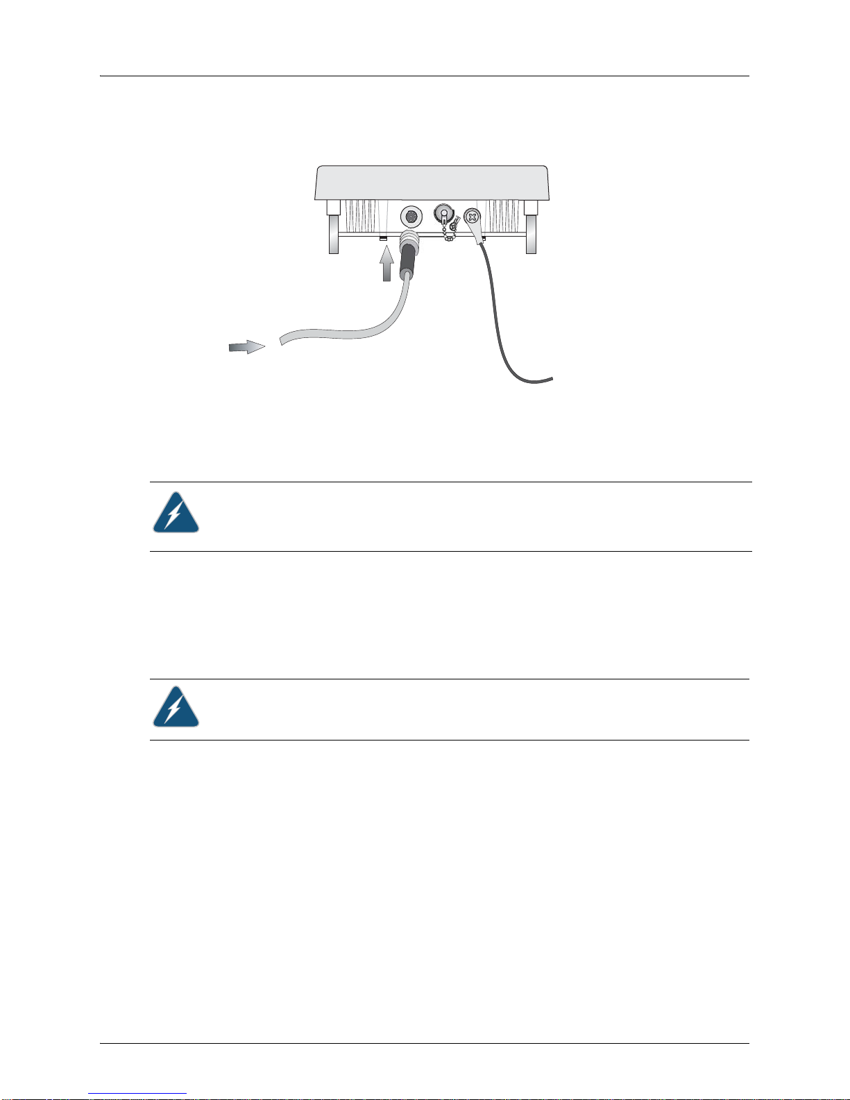
1. Connect the Ethernet cable and a grounding wire to the unit.
2. Mount the unit on a wall, pole, mast, or tower using the mounting bracket.
3. Mount external antennas on the same supporting structure as the WLA620 and
connect them to the unit.
4. Connect the power injector to the Ethernet cable, a local LAN switch, and an AC
power source.
5. For wireless bridge or Mesh Services installations, align antennas at the bridge or
mesh link endpoints.
Copyright © 2012, Juniper Networks, Inc. 3
Page 38

Instal ling and Conn ecting an Acces s Point
Attach bracket to
pole with mounting
grooves facing up
Mounting the Unit
You can mount the WLA620 using either the pole-mounting bracket or the
wall-mounting bracket. Use one of the following procedures.
Informational Note: If you are installing the WLA620 as a Mesh WLA in a WLAN Mesh or
wireless bridge configuration, and the WLA will not have a wired link to a WLA, you must
configure the WLA connection using a wired link to an WLC switch before deploying the
WLA620 in a final location.
Using the Pole-Mounting Bracket
Perform the following steps to mount the unit to a 3.81 to 5.08 cm (1.5 to 2 inch)
diameter steel pole or tube using the mounting bracket:
1. Always attach the bracket to a pole with the open end of the mounting grooves
facing up.
2. Place the U-shaped part of the bracket around the pole and tigh ten the secu ring nut
just enough to hold the bracket to the pole. (The bracket may need to be rotated
around the pole during the alignment process.)
3. Use the included nuts to tightly secure the WLA620 to the bracket.
Mounting on Larger Diameter Poles
In addition, there is a method for attaching the pole-mounting bracket to a pole that is
5.08 to 12.7 cm (2 to 5 inches) in diameter using an adjustable steel band strap (not
included in the kit). A steel band strap up to 0.5 inch (1.27 cm) wide can be threaded
through the main part of the bracket to secure it to a larger diameter pole without using
the U-shaped part of the bracket. This method is illustrated in the following figure.
Figure 3–2. Attaching the Bracket Using a Steel Band Strap
Figure 3–1. Attaching the Bracket to the Pole
4 Copyright © 2012, Juniper Networks, Inc.
Page 39

Steel Band Clamp
Mounting Grooves
Using the Wall-Mounting Bracket
Perform the following steps to mount the unit to a wall using the wall-mounting br acket:
1. Always attach the bracket to a wall with the open end of the mounting grooves
facing up (see following figure).
Installing and Connecting an Access Point
Figure 3–3. Wall-Mounting Bracket
2. Position the bracket in the intended location and mark the position of the three
mounting screw holes.
3. Drill three holes in the wall that match the screws and wall plugs included in the
bracket kit, then secure the bracket to the wall.
4. Use the included nuts to tightly secure the WLA620 to the bracket.
Connecting External Antennas
When deploying an WLA620, you must mount external antennas and connect them to
the unit. Typically, access point operation requires a 2. 4 GHz antenna, and brid ge link
operation requires a 5 GHz antenna.
Perform these steps:
1. Mount the external antenna to the same supportin g structure as the WLA620, within
3 m (10 ft) distance, using the bracket supplied in the antenna package.
2. If you are installing the optional lightning arrestor for an outdoor antenna, perform
the following steps. Otherwise, skip to step 5.
Copyright © 2012, Juniper Networks, Inc. 5
Page 40

Instal ling and Conn ecting an Acces s Point
To External AntennaTo WLA620
6-gauge
Grounding Cable
Grounding Nut
Locking Washer
Hex Nut
Lightning Protector
3. Solder the ground wire to the ground-wire terminal lug supplied with the lightning
arrestor. Junip er Networks recommends that you use 6-gauge cable for the ground
wire. The ground wire must be properly earthe d in or de r to pro vid e ad eq u at e
protection.
4. Attach the ground-wire terminal lug, lock washer, and hex nut to the lightning
arrestor, in the order shown in the figure below.
Informational Note: To meet regulatory requirements, you must ensure that the external
antenna specified with the set ap radio antenna type command exactly matches the
external antenna attached to the WLA620 external antenna port.
Figure 3–4. Attaching the Ground-Wire Terminal Lug, Lock W asher, and Hex Nut to the
Lightning Arrestor
a. Connect one end of the short RF coaxial cable to the WLA620 N-type connector,
and connect the other end to the lightning arrestor.
b. Connect one end of the 3m RF coaxial cable to the lightning arrestor, and
connect the other end to the outdoor antenna. Continue with step 6.
5. Connect the antenna to the WLA620 N-type connector using the RF coaxial cable
provided in the antenna package.
6. Apply weatherproofing tape to the antenna connectors to help prevent water
entering the connectors.
6 Copyright © 2012, Juniper Networks, Inc.
Page 41

Installing and Connecting an Access Point
RF Coaxial Cable
2.4 GHz External
Omnidirectional
Antenna
2.4 GHz
N-type Connector
5 GHz
N-type Connector
5 GHz External
High-gain Panel
Antenna
Optional
Lightning
Protector
MP-620
Figure 3–5. Connecting External Antennas to the WLA620
Connecting Cables to the Unit
1. Ground the unit with an appropriate grounding wire (not included) by attaching it to
the grounding screw on the unit
2. Attach the Ethernet cable to the Ethernet port on the WLA620.
Informational Note: The Ethernet cable included with the package is 30 m (100 ft) long.
To wire a longer cable (maximum 100 m, 325 ft), use the connector pinout information in
Appendix B.
3. For extra protection against rain or moisture, apply weatherproofing tape (not
included) around the Ethernet connector.
Caution: Be sure that grounding is available and that it meets local and national electrical
codes. For additional lightning protection, use lightning rods, lightning arrestors, or surge
suppressors.
Copyright © 2012, Juniper Networks, Inc. 7
Page 42

Instal ling and Conn ecting an Acces s Point
Ground Wire
Ethernet Cabl e
Ethernet Cable
(Cat 5 cable)
WLA, server or
other device
Ethernet port
Figure 3–6. Attaching an Ethernet Cable to the WLA620
Connecting the Power Supply
Contact a fully qualified electrician to perform the installation.
Connecting an WLA to an WLC
You can connect an WLA directly to an WLC or indirectly to the WLC through an
intermediate Layer 2 or Layer 3 network. If you are connecting the WLA directly to an
WLC, use the following procedure to insert the cable into the WLC and verify the link.
Y ou can use the CLI or RingMaster to configure an WLA connection. If you are installing
the WLA620 as a Mesh WLA in a WLAN Mesh or wireless bridge configuration, you
must configure the WLA connection before deploying the WLA620 in its final location.
Figure 3–7 below shows how to insert a Cat 5 cable into 10/100 Ethernet port on an
WLC. Refer to this figure as you perform the procedure.
1. Insert a Cat 5 cable with a standard RJ45 connector as shown in Figure 3–7. For
connection to an WLA, use a straight-through cable.
Figure 3–7. 10/100 Cat 5 Cable Installation
2. When the link is activated, observe the WLA LED for the port on the WLC:
8 Copyright © 2012, Juniper Networks, Inc.
Page 43

Table 1: WLA Port LED Behavior
WLC Port LEDs for WLA
Connections
Solid green For an WLA access point active link, all the following are
Alternating green and amber WLA is booting with an image received from the WLC
Solid amber PoE is on.
Blinking amber WLA is unresponsive or there is a PoE problem.
Unlit PoE is off.
Meaning
true:
WLA has booted.
WLA has received a valid configuration from the MX
switch.
Management link with an MP is operational.
At least one radio is enabled or is in sentry mode.
For an WLA secondary link, the link is present.
switch. After the access point boots and receives its
configuration, this LED appearance persists until a radio
is enabled or is placed in sentry mode.
Informational Note: A WLC switch 10/100 Ethernet ports are configured as wired
network ports by default. You must change the port type for an WLC port directly
connected to an WLA to activate the link.
Installing and Connecting an Access Point
Aligning Antennas for Bridge or Mesh Links
If you are installing WLA620 units for wireless bridge or Mesh Services operation, after
the units have been mounted, connected, and the radios are operating, the antennas
must be accurately aligned to ensure optimum performance on the bridge or mesh
links.
This alignment process is particularly important for long-range point-to-point links. In a
point-to-multipoint configuration, the Mesh Portal WLA uses an omnidirectional or
sector antenna, which does not require alignment, but Mesh WLAs still need to be
correctly aligned with the Mesh Portal antenna.
Point-to-Point Configurations – In a point-to-point configuration, the alignment
process requires two people at each end of the link. The use of cell phones or
two-way radio communication may help with coordination. To start, you can just point
the antennas at each other, using binoculars or a compass to set the general
direction. For accurate alignment, you must connect a DC voltmeter or RSSI meter
to the BNC connector on the WLA620 and monitor the voltage as the ante nna moves
horizontally and vertically.
Point-to-Multipoint Configurations – In a point-to-multipoint configuration all Mesh
WLAs must be aligned with the Mesh Portal antenna. The alignment process is the
same as for point-to-point links, but only the Mesh WLA end of the link requires the
alignment.
The WLA620 BNC connector provides an output voltage between 0 and 3.28 VDC that
is proportional to the received radio signal strength. The higher the voltage rea ding, the
stronger the signal. The radio signal from the remote antenna can be seen to have a
strong central main lobe and smaller side lobes. The object of the alignment process is
to set the antenna so that it is receiving the strongest signal from the central main lobe.
Copyright © 2012, Juniper Networks, Inc. 9
Page 44

Instal ling and Conn ecting an Acces s Point
Main Lobe
Maximum
Horizontal Scan
Vertical Scan
RSSI
Voltage
Side Lobe
Maximum
RSSI Voltage
Remote
Antenna
Maximum Signal Strength Position
for Horizontal Alignment
Maximum Signal
Strength Position for
Vertical Alignment
Figure 3–8. Aligning the WLA620 Antenna According to Signal Strength
To align the antennas in the link using the output voltage, start with one antenna fixed
and then perform the following procedure to align the other antenna:
1. Optionally configure the WLA with the fixed ante nna to send lin k calibration pa cket s.
set ap
2. On the WLA620, remove the BNC connector cover and connect a DC voltmeter or
Figure 3–9. Connecting a Vo ltmeter to the WLA620
A link calibration packet is an unencrypted 802.11 management packet of type
Action. When enabled on an WLA radio, link calibration packets are sent at a rate of
5 per second. When the WLA620 receives a link calibration packet, it emits a
voltage to the RSSI meter proportional to the received sig nal strength of the packet .
This can aid in positioning the WLA620 where it has a strong signal to the WLA
sending out the packets.
To configure an WLA radio to send out link calibration packets, use the following
command on the WLC:
num
radio
num link-calibration
mode {
enable
|
disable
}
Only one radio on a WLA can be configured to send link calibration packets. Link
calibration packets are intended to be used only during installatio n of WLAs and not
on a continual basis.
RSSI meter using a cable with a male BNC connector (not included).
10 Copyright © 2012, Juniper Networks, Inc.
Page 45

Installing and Connecting an Access Point
Voltmeter
RSSI BNC
Connection
3. Pan the antenna horizontally back and forth while checking the RSSI voltage. If
using the pole-mounting bracket with the WLA620, you must rotate the mounting
bracket around the pole. Other external antenna brackets may require a different
horizontal adjustment.
4. Find the point where the signal is strongest (highest voltage) and secure the
horizontal adjustment in that position.
Informational Note: Sometimes there may not be a central lobe peak in the voltage
because vertical alignment is too far off and only two similar peaks for the side lobes are
detected. In this case, fix the antenna so that it is halfway between the two peaks.
5. Loosen the vertical adjustment on the mounting bracket and tilt the antenna slowly
up and down while checking the RSSI voltage.
6. Find the point where the signal is strongest and secure the vertical adjustment in
that position.
7. Remove the voltmeter cable and replace the connector cover.
Copyright © 2012, Juniper Networks, Inc. 11
Page 46

Instal ling and Conn ecting an Acces s Point
Installing a WLA622
The WLA622 includes a bracket kit for mounting the unit to a 3.81 to 5.08 cm (1.5 to
2-inch) diameter steel pole or tube. The pole-mounting bracket allows the unit to be
mounted to part of a radio mast or tower structure. The unit also has a wall-mounting
bracket kit that enables it to be installed on a building wall or roof when using external
antennas.
Hardware installation of the WLA622 involves these steps:
1. Connect the Ethernet cable and a grounding wire to the unit.
2. Mount the unit on a wall, pole, mast, or tower using the mounting bracket.
3. Mount external antennas on the same supporting structure as the WLA622 and
connect them to the unit.
4. Connect the power injector to the Ethernet cable, a local LAN switch, and an AC
power source.
5. For wireless bridge or Mesh Services installations, align antennas at the bridge or
mesh link endpoints.
Mounting the Unit
You can mount the WLA622 using either the pole-mounting bracket or the
wall-mounting bracket. Use one of the following procedures.
Informational Note: If you are installing the WLA622 as a Mesh WLA in a WLAN Mesh or
wireless bridge configuration, the WLA does not have a wired link to an WLC. You must
configure the WLA connection using a wired link to an WLC before deploying the WLA622
in a final location.
Using the Pole-Mounting Bracket
Perform the following steps to mount the unit to a 3.81 to 5.08 cm (1.5 to 2-inch)
diameter steel pole or tube using the mounting bracket:
Informational Note: Always attach the bracket to a pole with the open end of the
mounting grooves facing up.
1. Place the V-shaped part of the bracket around the pole and tighten the securing
nuts just enough to hold the bracket to the pole. (The bracket may need to be
rotated around the pole during the alignment process.)
12 Copyright © 2012, Juniper Networks, Inc.
Page 47

Installing and Connecting an Access Point
Figure 3–10. Attaching the Bracket to the Pole
2. Fit the edges of the V - shaped p art into the slots in the r ectangular pla te, and use the
included nuts to tightly secure the WLA622 to the bracket.
Copyright © 2012, Juniper Networks, Inc. 13
Page 48

Instal ling and Conn ecting an Acces s Point
3. Attach the adjustable rectangular plate to the bridge with supplied screws.
4. Attach the bridge with bracket to the plate already fixed to the pole.
5. Use the included nuts to secure the wireless bridge to the pole bracket. Note that
the wireless bridge tilt angle may need to be adjusted during the antenna alignment
process. Be sure to take account of the antenna polarization direction. All antennas
in a link must be mounted with the same polarization.
14 Copyright © 2012, Juniper Networks, Inc.
Page 49

Installing and Connecting an Access Point
Mounting on Larger Diameter Poles
There is also a method for attaching the pole-mounting bracket to a pole that is 5.08 to
12.7 cm
(2 to 5 inches) in diameter using an adjustable steel band strap (not included in the kit).
A steel band strap up to 1.27 cm (0.5 inch) wide can be threaded throu gh the main part
of the bracket to secure it to a larger diameter pole without using the U-shaped part of
the bracket. This method is illustrated in the following figure.
Using the Wall-Mounting Bracket
Perform the following steps to mount the unit to a wall using the wall-mounting br acket.
Informational Note: The wall-mounting bracket does not allow the integrated antenna
of the wireless bridge to be aligned. It is intended for use with the unit using an external
antenna.
Figure 3–11. Attaching the Bra cke t Usin g a Steel Band strap
1. Always attach the bracket to a wall with the flat side flush against the wall (see
following figure).
Copyright © 2012, Juniper Networks, Inc. 15
Figure 3–12. Wall-Mounting Bracket
Page 50

Instal ling and Conn ecting an Acces s Point
2. Position the bracket in the intended location and mark the position of the four
mounting screw holes.
3. Drill four holes in the wall that match the screws and wall plugs included in the
bracket kit, then secure the bracket to the wall.
4. Use the included nuts to tightly secure the WLA622 to the bracket.
Connecting External Antennas
For some applications, when deploying an WLA622, you must mount external antennas
and connect them to the unit. Typically, access point operation requires a 2.4 GHz
antenna, and bridge link operation requires a 5.0 GHz antenna.
The primary port for 802.11bg (2.4Ghz) is port 1 and the primary port for 802.11a is Port
3. The WLA622 supports one or two antennas connected to each band. If you install
one antenna it must be installed in the primary port. If you install two antennas they
must be the same antenna model. There are no additional configuration requirements
for adding the second antenna. If antenna diversity between the two antennas is a
desired option it must be configured.
The default for the 802.11bg radio is ANT-1360-OUT.
set ap apnum radio num antennatype {ANT-1120-OUT | ANT-1360-OUT |
The antenna-location must be either indoors or outdoors. Placing and configuring one
antenna indoors and the other outdoors is not allowed.
set ap apnum antenna-location {indoors | outdoors}
To connect external antennas follow these steps:
1. Mount the external antenna to the same supportin g structure as the WLA622, within
2. If you are installing the optional lightning arrestor for an outdoor antenna, perform
the following steps. Otherwise, skip to step 5.
ANT-5360-OUT | ANT-5120-OUT | ANT-5PNL-OUT}
10 ft (3 m) distance, using the bracket supplied in the antenna package.
16 Copyright © 2012, Juniper Networks, Inc.
Page 51

Installing and Connecting an Access Point
To External Antenna
To MP-632
6-gauge
Grounding Cable
Grounding Nut
Locking Washer
Hex Nut
Lightning Protector
a. Solder the ground wire to the ground-wire terminal lug supplied with the lightning
arrestor. Junip er Networks recommends that you use 6-gauge cable for the
ground wire. The ground wire must be properly earthed in order to provide
adequate protection.
b. Attach the ground-wire terminal lug, lock washer, and hex nut to the lightning
arrestor, in the order shown in Figure 3–4 below.
Informational Note: To meet regulatory requirements, you must ensure that the external
antenna specified with the set ap radio antennatype command exactly matches the
external antenna attached to the WLA622 external antenna port.
Figure 3–13. Attaching the Ground-Wire Terminal Lug, Lock Washer, and Hex Nut to
the Lightning Arrestor
c. Connect one end of the short RF coaxial cable to the WLA622 N-type connector,
and connect the other end to the lightning arrestor.
d. Connect one end of the 3m RF coaxial cable to the lightning arrestor, and
connect the other end to the outdoor antenna. Continue with step 6.
3. Connect the antenna to the WLA622 N-type connector using the RF coaxial cable
provided in the antenna package.
4. Apply weatherproofing tape to the antenna connectors to help prevent water
entering the connectors.
Copyright © 2012, Juniper Networks, Inc. 17
Page 52

Instal ling and Conn ecting an Acces s Point
RF Coaxial Cable
2.4 GHz External
Omnidirectional
Antenna
2.4 GHz N-type Connector
5 GHz
N-type Connector
5 GHz External
High-gain Panel
Antenna
Figure 3–14. Connecting External Antennas to the WLA622
Connecting Cables to the Unit
1. Ground the unit with an appropriate grounding wire (not included) by attaching it to
2. Attach the Ethernet cable to the Ethernet port on the WLA622.
3. For extra protection against rain or moisture, apply weatherproofing tape (not
4. Be sure to install a lightning arrestor on the Ethernet cable between the bridge and
the grounding screw on the unit.
included) around the Ethernet connector.
power injector. The li ghtning arrestor should be placed outdoo rs, immediately before
the Ethernet cable enters the building.
Caution: Be sure that grounding is available and that it meets local and national electrical
codes. For additional lightning protection, use lightning rods, lightning arrestors, or surge
suppressors.
18 Copyright © 2012, Juniper Networks, Inc.
Page 53

Installing and Connecting an Access Point
Figure 3–15. Attaching an Ethernet Cable to the WLA622
Connecting the Power Supply Unit
Contact a fully qualified electrician to perform the installation.
To connect the wireless bridge to a PSU:
Informational Note: The Ethernet port on the wireless bridge does not support Power
over Ethernet (PoE) based on the IEEE 802.3af standard. Do not try to power the unit by
connecting it directly to a WLC that provides IEEE 802.3af PoE. For power, always connect
the unit only to the included WLA-XPS9001GO PSU.
1. Connect the Ethernet cable from the wireless bridge to the PoE port labeled “DATA
PWR OUT” on the PSU..
Copyright © 2012, Juniper Networks, Inc. 19
Page 54

Instal ling and Conn ecting an Acces s Point
Caution: The DATA IN port on the PSU is not used.
2. The WLA-XPS9001GO PSU is shipped with an North American (NA) power cable
connected to the standard AC recept acle on the PSU. For international users, inst all
your own nationally-approved AC plug to the power cable.
3. Plug the other end of the power cable into a grounded, 3-pin socket, AC power
source
Informational Note: International users must use a nationally approved AC plug
appropriate for your country.
Checking the LED Indicators
The 11a and 11b/g LEDs on the WLA622 operate in two display modes, which are
configurable through the software. The default WLA mode indicates data traffic rates.
The RSSI mode indicates the received signal power and is used when aligning
antennas in a bridge link.
When the bridge is connected to power, the LEDs function as follows:
Table 2: 11a and 11b/g LED Behavior on the WLA622
LED Appearance Meaning
Power Green The bridge is powered up and operating normally.
Off The bridge is not receiving power or there is a fault with the power
supply.
Amber The system is under cold reset status.
Link Green The bridge has a 10/100 Mbps Fast Ethernet connection, but there
is no activity.
Flashing Indicates that the bridge is transmitting or receiving data on a
10/100 Mbps Ethernet LAN. Flashing rate is proportional to
network activity.
Off No link is present or the Ethernet LAN port is disabled.
11a
(Three LEDs)
Green and Flashing The 802.11a 5.3 GHz radio is enabled.
RSSI Mode:
One fully lit LED indicates a low RSSI output level, two LEDs.a
medium level, and three LEDs the maximum level.
A flashing LED indicates an intermediate RSSI output level WLA
Mode:
One fully lit LED indicates a low traffic rate, two LEDs.a medium
rate, and three LEDs the maximum rate.
A flashing LED indicates an intermediate traffic rate level
Off No link is present or the 802.11a radio is disabled.
20 Copyright © 2012, Juniper Networks, Inc.
Page 55

Table 2: 11a and 11b/g LED Behavior on the WLA622
Ethernet Cable
(Cat 5 cable)
WLA, server or
other device
Ethernet port
LED Appearance Meaning
11g
(Three LEDs)
Amber and Flashing The 802.11g 2.4 GHz radio is enabled.
RSSI Mode:
One fully lit LED indicates a low RSSI output level, two LEDs.a
medium level, and three LEDs the maximum level.
A flashing LED indicates an intermediate RSSI output level WLA
Mode:
One fully lit LED indicates a low traffic rate, two LEDs.a medium
rate, and three LEDs the maximum rate.
A flashing LED indicates an intermediate traffic rate level
Off No link is present or the 802.11g radio is disabled.
Connecting a WLA to a WLC
Informational Note: For lightning protection at the power injector end of the cable,
consider using a lightning arrestor immediately before the cable enters the building.
Installing and Connecting an Access Point
You can connect a WLA directly to an WLC or indirectly to the WLC through an
intermediate Layer 2 or Layer 3 network. If you are connecting the WLA directly to an
WLC, use the following procedure to insert the cable into the WLC and verify the link.
You can use the CLI or RingMaster to configure a WLA connection. If you are installing
the WLA622 as a Mesh WLA in a WLAN Mesh or wireless bridge configuration, you
must configure the WLA connection before deploying the WLA622 in its final location.
(See the Mobility System Software Configuration Guide.)
The figure below shows how to insert a Cat 5 cable into 10/100 Ethernet port on an
WLC. Refer to this figure as you perform the procedure.
Figure 3–16. 10/100 Cat 5 Cable Installation
1. Insert a Cat 5 cable with a standard RJ45 connector as shown in Figure 3–7. For
connection to an WLA, use a straight-through cable.
Copyright © 2012, Juniper Networks, Inc. 21
Page 56

Instal ling and Conn ecting an Acces s Point
2. When the link is activated, observe the WLA LED for the port on the WLC.
Table 3: WLC Port LEDs for WLA Connections
WLC Port LEDs for
WLA Connections
Solid green For an WLA active link, all the following are true:
Alternating green and
amber
Solid amber PoE is on.
Blinking amber WLA is unresponsive or there is a PoE problem.
Unlit PoE is off.
Informational Note: The WLC 10/100 Ethernet ports are configured as wired network
ports by default. You must change the port type for an WLC port directly connected to a
WLA to activate the link. (See the Wireless Lan Controller Installation and Basic
Configuration Guide.)
Meaning
WLA has booted.
WLA has received a valid configuration from the WLC.
Management link with an WLA is operational.
At least one radio is enabled or is in sentry mode.
For a WLA secondary link, the link is present.
WLA is booting with an image received from the WLC switch.
After the access point boots and receives its configuration, this
LED appearance persists until a radio is enabled or is placed in
sentry mode.
Aligning Antennas for Bridge or Mesh Links
If you are installing WLA622 units for wireless bridge or Mesh Services operation, after
the units have been mounted, connected, and the radios are operating, the antennas
must be accurately aligned to ensure optimum performance on the bridge or mesh
links.
This alignment process is particularly important for long-range point-to-point links. In a
point-to-multipoint configuration, the Mesh Portal WLA uses an omnidirectional or
sector antenna, which does not require alignment, but Mesh WLAs still need to be
correctly aligned with the Mesh Portal antenna.
Point-to-Point Configurations – In a point-to-point configuration, the alignment
process requires two people at each end of the link. The use of cell phones or
two-way radio communication may help with coordination. To start, you can just point
the antennas at each other, using binoculars or a compass to set the general
direction. For accurate alignment, monitor the RSSI’s LED indicator as yo u move the
antenna horizontally and vertically.
Point-to-Multipoint Configurations – In a point-to-multipoint configuration all Mesh
WLAs must be aligned with the Mesh Portal antenna. The alignment process is the
same as for point-to-point links, but only the Mesh WLA end of the link requires the
alignment.
The LEDs are viewed right to left as you look at the back of the WLA. The range from 1
to 12 will cover the signal range to accurately align the antenna. The signal strength
LEDs indicate the received radio signal strength for a particular bridge link. The more
LEDs that turn on, the stronger the signal. (RSSI level 1 should equate to the lowest
useful signal). Alternatively, you can monitor the Receive Signal Strength Indicator
(RSSI) value directly from the management interface. The higher the RSSI value, the
stronger the signal.
22 Copyright © 2012, Juniper Networks, Inc.
Page 57

Installing and Connecting an Access Point
Main Lobe
Maximum
Horizontal Scan
Vertical Scan
RSSI
Value
Side Lobe
Maximum
RSSI Value
Remote
Antenna
Maximum Signal Strength Position
for Horizontal Alignment
Maximum Signal
Strength Position for
Vertical Alignment
When you move the antenna during alignment, the radio signal from the remote
antenna can be seen to have a strong central main lobe and smaller side lobes. The
object of the alignment process is to set the antenna so that it is receiving the strongest
signal from the central main lobe.
Figure 3–17. Aligning the WLA622 Antenna According to Signal Strength
When aligning the antennas the WLA with the antenna that is being aligned to must be
set to send link-calibration packets. Use the following command to setup the WLA that
the WLA622 is being aligned with.
set ap num radio num link-calibration mode {enable | disable}
Link-calibration should be disabled under normal operation of the WLA.
If the WLA622 is installed with two directional anten nas, connect the firs t antenna to the
primary antenna port with antenna diversity off and align it. Then disconnect the first
antenna and connect the second antenna to the primary antenna port. If the second
antenna is being aligned with a different WLA, disable link-calibration on the original
WLA and enable it on the new WLA. Once both antennas are properly aligned, connect
them to their desired ports.
Copyright © 2012, Juniper Networks, Inc. 23
Page 58

Instal ling and Conn ecting an Acces s Point
To align the antennas in the link using the output LEDs, st art with on e antenna fixed and
then perform the following procedure to align the other antenna:
1. Pan the antenna horizontally back and forth while checking the RSSI LEDs. If using
the pole-mounting bracket with the WLA622, you must rotate the mounting bracket
around the pole. Other external antenna bracke t s may requ ire a d if fer ent horizont a l
adjustment.
2. Find the point where the signal is strongest (all LEDs on) and secure the horizontal
adjustment in that position.
Informational Note: Sometimes there may not be a central lobe peak in the RSSI LED
indicators because vertical alignment is too far off and only two similar peaks for the side
lobes are detected. In this case, fix the antenna so that it is halfway between the two
peaks.
3. Loosen the vertical adjustment on the mounting bracket and tilt the antenna slowly
up and down while checking the LEDs.
Find the point where the signal is strongest and secure the vertical adjustment in that
position.
24 Copyright © 2012, Juniper Networks, Inc.
Page 59

Installing and Connecting an Access Point
Installing a WLA632
The WLA632 includes a bracket kit for mounting the unit to a 3.81 to 5.08 cm (1.5 to
2-inch) diameter steel pole or tube. The unit also has a wall-mounting bracket kit that
can be used to install the unit on a building wall. You also have the option to mount the
WLA on a larger pole (up to 30.48 cm or 12-inch diameter) using the bracket kit and two
metal band straps (straps not provided by Juniper Networks). Hardware installation of
the WLA632 involves these steps:
1. Mount the unit on a wall, pole, mast, or tower using the mounting bracket.
2. Mount external antennas on the same supporting structure as the WLA632 and
connect them to the unit.
3. Connect the Ethernet cable and a grounding wire to the unit.
4. Connect the other end of the circular DIN power cable to the WLA-XPS9001GO.
War n ing: The WLA632 must only be used with a Juniper Networks approved
WLA-XPS9001GO PSU in order to prevent possible damage to the unit.
5. Connect the circular DIN Ethernet cable and prepare the RJ45 cable with the
waterproof cover that is provided.
Informational Note: Any additional cabling used in the assembly should be a
minimum UL CMX outdoor-rated or equivalent.
Mounting the Unit
Y ou can mount the WLA632 usin g either the wall-mounting bracket or the wall-mounting
bracket combined with the pole-mounting bracket (bracket s are provided for bo th a 3.81
to 5.08 cm (1.5 to 2-inch) diameter steel pole or tube or a larger size pole or tube). Use
one of the following procedures.
Using the Pole-Mounting Bracket
Perform the following steps to mount the unit to a 3.81 to 5.08 cm (1.5 to 2-inch)
diameter steel pole or tube using the mounting bracket:
Copyright © 2012, Juniper Networks, Inc. 25
Page 60

Instal ling and Conn ecting an Acces s Point
1. Insert the four large screws (included in kit) through the four circular holes in the
bracket as shown below.
2. Position the flat bracket behind the pole as shown below and align the screws on
the front bracket with the holes in the flat bracket.
26 Copyright © 2012, Juniper Networks, Inc.
Page 61

Installing and Connecting an Access Point
3. Insert the four screws into the holes on the flat bracket and secure the brackets to
the pole using the provided split washers and nuts.
4. Position the WLA632 unit so that the mounting holes ov er lap with th e sam e -s ize d
holes on the pole-mounting bracket.
Copyright © 2012, Juniper Networks, Inc. 27
Page 62

Instal ling and Conn ecting an Acces s Point
5. Use the 2 small bolts and washers (included in kit) to tightly secure the WLA632 to
the pole-mounting bracket.
.
Informational Note: This pole mounting procedure can also be used to attached the
WLA632 unit to a horizontal pole.
Mounting on Larger Diameter Poles
There is also a method for attaching the pole-mounting b racket to a larger diameter pole
using two adjustable steel band straps (not included in the kit). The two steel band
straps can be threaded through the rectangular holes in the bracket to secure it to a
larger diameter pole. This method is shown in the following figure.
28 Copyright © 2012, Juniper Networks, Inc.
Page 63

Installing and Connecting an Access Point
Figure 3–18. Attaching the Bracket Using Steel Band Straps
Using the Wall-Mounting Bracket
Perform the following steps to mount the unit to a wall using the wall-mounting bracket.
Informational Note: Always attach the bracket to a wall with the flat side flush
against the wall (see following figure).
Figure 3–19. Wall-Mounting Bracket
1. Position the bracket on the intended wall location and drill four large screws (not
included in kit) in through the circular holes on the bracket until it is firmly secured to
the wall.
Copyright © 2012, Juniper Networks, Inc. 29
Page 64

Instal ling and Conn ecting an Acces s Point
2. Position the WLA632 unit so that the mounting holes ov er lap with th e sam e -s ize d
holes on the wall-mounted bracket..
3. Use the 2 small bolts and washers (included in kit) to tightly secure the WLA632 to
the wall-mounted bracket.
Connecting External Antennas
The supported antennas models are:
802.11bgn Radio
ANT-7360A-OUT (stick, N-type jack) If this antenna is used the unused center
antenna port must be terminated.
ANT-77555-OUT (3 RP-SMA jack)
30 Copyright © 2012, Juniper Networks, Inc.
Page 65

ANT-74520-OUT (3 RP-SMA)
802.11an Radio
ANT-7360A-OUT (stick)
ANT-74520-OUT (3 RP-SMA)
ANT-77555-OUT (3 RP-SMA)
ANT-5007-OUT (2 N-type)
The port usage depends on the antennas in use. If the OMNI antennas are used there
must be 3 antennas installed for the radio. If an antenn a is used then the two e dge ports
must be connected to the antenna (ports 4 and 6). The middle port will be turned off by
the software and should be terminated. If either the ANT-77555 or 74520 are used all
three connectors must be connected to the WLA for the correct radio.
set ap apnum radio num antennatype {ANT-7360A-OUT | ANT-77555-OUT |
ANT-74520-OUT | ANT-5O07-OUT} …
The antenna-location must be either indoors or outdoors. Although this is an outdoor
WLA it may be used indoors. The following command is per radio.
set ap apnum antenna-location {indoors | outdoors}
Informational Note: Splitting the antennas between indoors and outdoors is not
allowed.
Installing and Connecting an Access Point
Multiple External Antenna Support
The WLA632 supports the use of multiple antenna ports per radio. Since there are
always multiple antennas connected, antenna diversity is always on. The command to
set the number of external antennas does not apply to the WLA632. The number of
antenna ports in use is determined by the antenna type.
set ap num radio num external-antennas num
If the external-antenna command is used for the WLA632 it will be ignored at the CLI.
If the ANT-5007-OUT antenna is in use on the 11a/n radio then the radio configuration
will revert to 2 x 3 mode rather than 3 x 3 mode and the middle port for the radio must
not be used.
Ethernet
The WLA632 supports a single IEEE 802.3-compliant auto-sensing 10/100/1000 BaseT
Ethernet interface on the Ethernet input connector. The WLA is configured as auto
MDI/MDIX and is powered from the WLA-XPS9001GO power supplies.
Caution: The WLA622 and WLA632 must only be used with a Juniper
Networks-approved WLA-XPS9001GO power supply in order to prevent possible damage
to the unit.
The WLA632 receives separate primary 48VDC power input and Ethernet signal from
separate 48VDC and Ethernet input connectors.
Caution: If you convert the 8 pin female circular DIN data port on the WLA632 bulkhead
to a standard RJ45 waterproof connection for the 10/100/1000 data port, PoE on the
10/100/1000 port must be disabled to prevent service interruption.The WLA632 does not
support PoE on the 10/100/1000 Ethernet data port.
Copyright © 2012, Juniper Networks, Inc. 31
Page 66

Instal ling and Conn ecting an Acces s Point
To External AntennaTo WLA unit
6-gauge
Grounding Cable
Grounding Nut
Locking Washer
Hex Nut
Lightning Protector
Informational Note: Any additional cabling used in the assembly should be a minimum
UL CMX outdoor-rated or equivalent.
The WLA632 48VDC / Ethernet inputs provides primary and secondary lightning
protection on all conductors. (The 48VDC / Ethernet inputs to the WLA632 need
lightning protection because the power supply can be up to 100m away.)
The Ethernet interface supports a cable length of at least 100m over CAT5, CAT5e, or
CAT6 cable.
Figure 3–20. Attaching the Ground-Wire Terminal Lug, Lock Washer, and Hex Nut to
the Lightning Arrestor
1. Connect one end of the short RF coaxial cable to the WLA632 N-type connector,
and connect the other end to the lightning arrestor.
2. Connect one end of the 3m RF coaxial cable to the lightning arrestor, and connect
the other end to the outdoor antenna. Continue with step 6.
3. Connect the antenna to the WLA632 N-type connector using the RF coaxial cable
provided in the antenna package.
4. Apply weatherproofing tape to the antenna connectors to help prevent water
entering the connectors.
Connecting Cables to the Unit
1. Ground the unit with an appropriate grounding wire (not included) by attaching it to
the grounding screw on the unit
2. Attach the Ethernet cable to the Ethernet port on the WLA632.
3. For extra protection against rain or moisture, apply weatherproofing tape (not
included) around the Ethernet connector.
32 Copyright © 2012, Juniper Networks, Inc.
Page 67

Installing and Connecting an Access Point
4. Be sure to install a lightning arrestor on the Ethernet cable between the bridge and
power injector. The li ghtning arrestor should be placed outdoo rs, immediately before
the Ethernet cable enters the building.
Informational Note: Be sure that grounding is available and that it meets local and
national electrical codes. For additional lightning protection, use lightning rods, lightning
arrestors, or surge suppressors.
Connecting the Power Supply Unit
To connect the wireless bridge to a PSU:
Informational Note: The Ethernet port on the wireless bridge does not support Power
over Ethernet (PoE) based on the IEEE 802.3af standard. Do not try to power the unit by
connecting it directly to a network switch that provides IEEE 802.3af PoE. Always connect
the unit to the included power injector module.
Informational Note: The WLA622 and WLA632 must only be used with a Juniper
Networks-approved WLA-XPS9001GO outdoor power supply in order to prevent possible
damage to the unit.
1. Connect the Ethernet cable from the wireless bridge to the PoE port labeled “DATA
PWR OUT” on the PSU.
Informational Note: The DATA IN port on the PSU is not used.
2. The WLA-XPS9001GO PSU is shipped with an North American (NA) power cable
connected to the standard AC recept acle on the PSU. For international users, inst all
your own nationally-approved AC plug to the power cable.
3. Plug the other end of the power cable into a grounded, 3-pin socket, AC power
source.
Informational Note: International users must use a nationally approved AC plug
appropriate for your country.
Copyright © 2012, Juniper Networks, Inc. 33
Page 68

Instal ling and Conn ecting an Acces s Point
Checking the LED Indicators
The WLA632 has LEDs that provide status information for the device. The table below
lists the function of the LEDs.
Table 4: LED Functions
LED Appearance Meaning
Health Solid green All the following are true:
Management link with an WLC is operational.
WLA has booted.
WLA has received a valid configuration from an WLC.
At least one radio is enabled or is in sentry mode.
Solid amber WLA is waiting to receive boot instructions and a configuration
file from an WLC.
Alternating green and amber WLA is booting and receiving a configuration file from an WLC.
After the WLA boots and receives a configuration, this LED
appearance persists until a radio is enabled or is placed in sentry
mode.
Radio 1/ Radio 2 Solid green A client is associated with the radio.
Blinking green Associated client is sending or receiving traffic.
Blinking amber Non-associated client is sending or receiving traffic.
Alternating green and amber Radio is unable to transmit. This state can occur due to any of the
followin g:
Excessive radio interference in the environment is preventing
the radio from sending beacons.
DFS has detected radar and is restricting traffic.
The radio has failed.
Unlit Means one of the following:
Radio is disabled and active scan is enabled. (The radio is in
sentry mode.)
Radio is enabled, but no clients are associated with it.
The LEDs are also used to indicate RSSI signal level during mesh link calibration.
Connecting a WLA to an WLC
Informational Note: For lightning protection at the power injector end of the cable, use a
lightning arrestor immediately before the cable enters the building.
You can connect an WLA directly to an WLC or indirectly to the WLC through an
intermediate Layer 2 or Layer 3 network. If you are connecting the WLA directly to an
WLC, use the following procedure to insert the cable into the WLC and verify the link.
You can use the CLI or RingMaster to configure a WLA connection. If you are installing
the WLA632 as a Mesh WLA in a WLAN Mesh or wireless bridge configuration, you
must configure the WLA connection before deploying the WLA632 in its final location.
34 Copyright © 2012, Juniper Networks, Inc.
1. Insert a Cat 5 cable with a standard RJ45 connector. For connection to a WLA, use
a straight-through cable.
2. When the link is activated, observe the WLA LED for the port on the WLC:
Page 69

Installing and Connecting an Access Point
Table 5: WLC Port LEDs for WLA Connections
WLC Port LEDs for WLA
Connections
Solid green For an WLA active link, all the following are true:
Alternating green and amber WLA is booting with an image received from the WLC switch. After the access point
Solid amber PoE is on.
Blinking amber WLA is unresponsive or there is a PoE problem.
Unlit PoE is off.
Alternating green and amber WLA is booting with an image received from the WLC switch. After the access point
Solid amber PoE is on.
Meaning
WLA has booted.
WLA has received a valid configuration from the WLC switch.
Management link with an WLA is operational.
At least one radio is enabled or is in sentry mode.
For an WLA secondary link, the link is present.
boots and receives its configuration, this LED appearance persists until a radio is
enabled or is placed in sentry mode.
boots and receives its configuration, this LED appearance persists until a radio is
enabled or is placed in sentry mode.
Informational Note: The WLC 10/100 Ethernet ports are configured as wired network
ports by default. You must change the port type for an WLC port directly connected to a
WLA to activate the link.
Copyright © 2012, Juniper Networks, Inc. 35
Page 70

Instal ling and Conn ecting an Acces s Point
36 Copyright © 2012, Juniper Networks, Inc.
Page 71

WLA Series Technical Specifications
This chapter lists the technical specifications for the Juniper Networks WLA620,
WLA622, and WLA632. For detailed compliance information, see the Regulatory
Guide document.
Informational Note: This Listed Accessory is designed and approved to be used only with
Juniper Networks WLC models WLC8 and WLC2. (The WLC200 does not directly connect
to the WLA.)
Informational Note: The WLA radios are disabled by default and can be enabled only by
the system administrator using the RingMaster management application or the WLC’s
command-line interface (CLI).
Informational Note: Regulatory Obligation: The radio frequency band, operating
channels, and transmit power depend on the country of operation specified by the system
administrator using RingMaster or the WLC’s CLI.
WLA Mechanical and Compliance Specifications
Table 1 lists the mechanical and compliance specifications for the WLA620 and
WLA622.
Table 1: WLA620 and WLA622 Mechanical and Compliance Specifications
Specification Description
Maximum Channels
(Outdoor)
Data Rates 802.11a:
Maximum Clients 64 for the radio interface set to access point mode
Modulation Types 802.11a: BPSK, QPSK, 16-QAM, 64-QAM
Network Configuration Access Point Mode:
Based on the country of operation
6, 9, 12, 18, 24, 36, 48, 54 Mbps per channel
802.11g:
6, 9, 11, 12, 18, 24, 36, 48, 54 Mbps per channel
802.11b:
1, 2, 5.5, 11 Mbps per channel
802.11g: CCK, BPSK, QPSK, OFDM
802.11b: CCK, BPSK, QPSK
Infrastructure
Bridge Mode:
Point-to-point and point-to-multipoint
Copyright © 2012, Juniper Networks, Inc. 1
Page 72

WLA Series Technical Specifications
Table 1: WLA620 and WLA622 Mechanical and Compliance Specifications
Specification Description
Operating Frequency 802.11a:
Power Injector (WLA620) Input: 100-240 VAC, 47-63 Hz, 1.5 A
Power Injector (WLA622) Input: 90-240 VAC; 50/60 Hz
Physical Size (WLA620) 19.8 x 19.8 x 6.33 cm (7.8 x 7.8 x 2.49 in)
Physical Size (WLA622) 19.5 x 19 x 7.4 cm (7.68 x 7.48 x 2.91 in)
Weight (WLA620) 4.8 kg (10.58 lbs)
Weight (WLA622) 1.54 kg (3.4 lbs)
Temperature (WLA620) Operating: -33 to 55 °C (-27.4 to 131°F)
Temperature (WLA622) Operating: -30 to 55 °C (-22 to 131 °F)
Humidity 5% to 95% (non-condensing)
EMC Compliance (Class B) FCC Class B (US)
Radio Signal Certification FCC Part 15 15.407(b) (5 GHz)
Safety UL/cUL60950-1, IEC60950-1 (CB) and IEC60529 IP68 (NEMA250
Standards IEEE 802.3 10BASE-T, IEEE 802.3u 100BASE-TX,
5.15 GHz to 5.825 GHz based on country regulations
802.11b/g:
2.4 GHz to 2.4835 GHz based on country regulations
Output: 48 VDC, 1.2 A
Output: 48 Vdc/0.63A, 12Vdc/1A
Storage: -40 to 80 °C (-40 to 176 °F)
Storage: -40 to 80 °C (-40 to 176 °F)
RTTED 1999/5/EC
DGT (Taiwan)
FCC Part 15.247 (2.4 GHz)
IC RSS-210
EN 300.328, EN 302.893
EN 300 826, EN 301.489-1, EN 301.489-17
ETSI 300.328; ETS 300 826 (802.11b)
6P)
IEEE 802.11a, b, g
2 Copyright © 2012, Juniper Networks, Inc.
Page 73

Table 2 lists the mechanical and compliance specifications for the WLA632.
Table 2: WLA632 Mechanical and Compliance Specifications
Specification Description
Maximum Channels
(Outdoor)
Data Rates 802.11b/g/n Channel:
Modulation Types 802.11a: OFDM (BPSK, QPSK, 16-QAM, 64-QAM)
Each WLA632 will operate with a single base MAC Address, and will consume 64
sequential MAC Addresses after the base MAC address for a total of 32 addresses
allocated per radio
1 CH ~ 11 CH (FCC)
1 CH ~ 13 CH (ETSI)
1 CH ~ 14 CHs (Japan) Channel 14 required for 11b
802.11a/n Channel:
FCC (20 channels): 52, 56, 60, 64, 100, 104, 108, 112, 116, 120, 124, 128, 132, 136, 140, 149,
153, 157, 161, 165 (except for Hong Kong where 36-48 outdoor is allowed).
For indoor application only: channels 36-48.
EU (11 channels): 100, 104, 108, 112, 116, 120, 124, 128, 132, 136, 140. For indoor application
only: channels 36-48, 52-64+.
Japan (8 channels):
WLA Series Technical Specifications
802.11b/g:
DSSS (DBPSK, DQPSK, CCK)
OFDM (BPSK, QPSK, 16-QAM, 64-QAM)
802.11n:
DSSS (DBPSK, DQPSK, CCK)
OFDM (BPSK, QPSK, 16-QAM, 64-QAM)
Operating Frequency Radio 1 supports:
2.4 GHz to 2.4835 GHz: Channels 1 to 14.
Radio 2 supports:
5.15 GHz to 5.35 GHz: Channels 52 to 64 (36 to 48 for Hong Kong only as well as indoor
application)
5.47 GHz to 5.725 GHz: Channels 100 to 140
5.75 to 5.85 GHz: Channels 149 to 165
Power Injector Input: 48Vdc
Wei ght without bracket: 4.4 kgs (9.8 lbs)
with wall mount bracket: 5.08 kgs (11.2 lbs)
with bracket needed for small pole mount: kgs 5.4 (12 lbs)
with brac ket and straps for large pole mount: 5.2 kgs (11.5 lbs)
Temperature Operating: -40 to 55°C (-40 to 131°F)
Storage: -40 to 70 °C (-40 to 158 °F)
Humidity OK Each WLA632 will operate with a single base MAC Address, and will consume 64
sequential MAC Addresses after the base MAC address for a total of 32 addresses
allocated per radio
Copyright © 2012, Juniper Networks, Inc. 3
Page 74

WLA Series Technical Specifications
Table 2: WLA632 Mechanical and Compliance Specifications (continued)
Specification Description
EMC Compliance (Class B) USA : 47CFR(FCC) part 15 Subpart B - class B
Safety UL 60950-1
Federal Communications Commission Interference Statement
(United States)
This equipment has been tested and found to comply with the limits for a Class B digit al
device, pursuant to Part 15 of the FCC Rules. These limits are designed to provide
reasonable protection against harmful interference in a residential installation. This
equipment generates, uses and can radiate radio frequency energy and, if not installed
and used in accordance with the instructions, may cause harmful interference to radio
communications. However, there is no guarantee that interference will not occur in a
particular installation. If this equipment does cause harmful interference to radio or
television reception, which can be determined by turning the equipment off and on, the
user is encouraged to try to correct the interference by one of the following measures:
Increase the separation between the equipment and receiver.
Connect the equipment into an outlet on a circuit different from that to which the
Consult the dealer or an experienced radio/TV technician for help.
Canada: ICES 003, class B
EU&EFTA :ETSI EN55022: 1998 class B
Japan :VCCI (Japan) Class B
Australia:/New Zealand : AS/NZS CISPR 22 Class B
EU medical Directive EN 60601-1-2
CSA C22.2 No.60950-1-03
NEMA 4X
IP67
K44/K45 Surges
receiver is connected.
Caution: FCC Caution: Any changes or modifications not expressly approved by the party
responsible for compliance could void the user’s authority to operate this equipment.
This device complies with Part 15 of the FCC Rules. Operation is subject to the
following two conditions: (1) This device may not cause harmful interference, and (2)
this device must accept any interference received, including interference that may
cause undesired operation.
For product available in the USA/Canada market, only channel 1~11 can be operated.
Selection of other channels is not possible.
This device and its antenna(s) must not be co-located or operation in conjunction with
any other antenna or transmitter.
4 Copyright © 2012, Juniper Networks, Inc.
Page 75

WLA Series Technical Specifications
This device is going to be operated in 5.15~5.25GHz frequency ran ge, it is restricted in
indoor environment only..
Caution: FCC Notice: To comply with FCC part 15 rules in the United States, the system
must be professionally installed to ensure compliance with the Part 15 certification. It is the
responsibility of the operator and professional installer to ensure that only certified
systems are deployed in the United States. The use of the system in any other combination
(such as co-located antennas transmitting the same information) is expressly forbidden.
Caution: FCC Radiation Exposure Statement: This equipment complies with FCC
radiation exposure limits set forth for an uncontrolled environment. This equipment should
be installed and operated with minimum distance 20cm between the radiator and your
body
Caution: System Administrators and anyone involved in the installation of the WLAN
System are responsible for the proper setup and operation in accordance to all rules and
regulations of the country in which the equipment operates.
Canadian Department of Communications Industry Canada
Notice (Canada)
This digital apparatus meets the requirements of Canadian Interference-Causing
Equipment Regulation RSS-210.
This Class B digital apparatus complies with Canadian ICES-003.
Operation is subject to the following two conditions:
1. This device may not cause interference.
2. This device must accept any interference, including interference that may cause
undesired operation of the device.
Cet appareil numérique de la classe B conforme á la norme NMB-003 du Canada.
Country Code Statement: For product available in the USA/Canada market, only
channel 1~11 can be operated. Selection of other channels is not possible.
This device and its antenna(s) must not be co-located or operation in conjunction with
any other antenna or transmitter.
To reduce potential radio interference to other users, the antenna type and its gain
should be so chosen that the equivalent isotropically radiated power (e.i.r.p) is not more
than that permitted for successful communication.
This device has been designed to operate with the antennas listed below, and having a
maximum gain of [23.5] dB. Antennas not included in this list or having a gain greater
than [23.5] dB are strictly prohibited for use with this device. The required antenna
impedance is 50 ohms.
The device could automatically discontinue transmission in case of absence of
information to transmit, or operational failure. Note that this is not intended to prohibit
transmission of control or signaling information or the use of repetitive codes where
required by the technology.
The device for the band 5150-5250 MHz is only for indoor usag e to reduce potential fo r
harmful interference to co-channel mobile satellite systems.
The maximum antenna gain permitted (for devices in the band 5725-5825 MHz) to
comply with the e.i.r.p. limits specified for po int-to-point and non point-to- point operation
as appropriate, as stated in section A9.2(3).
Copyright © 2012, Juniper Networks, Inc. 5
Page 76

WLA Series Technical Specifications
The maximum antenna gain permitted (for devices in the bands 5250-5350 MHz and
5470-5725 MHz) to comply with the e.i.r.p. limit.
High-power radars are allocated as primary users (meaning they have priority) of the
bands 5250-5350 MHz and 5650-5850 MHz and these radars could cause interfere nce
and/or damage to LE-LAN devices.
Caution: IC Radiation Exposure Statement: This equipment complies with IC RSS-102
radiation exposure limits set forth for an uncontrolled environment. This equipment should
be installed and operated with minimum distance 20cm between the radiator & your body.
MAC Addresses
Each WLA is assigned a unique block of 64 MAC addresses. Each radio has 32 MAC
addresses and can therefore support up to 32 SSIDs, with one MAC address assigned
to each SSID as its BSSID.
The WLA ’s MAC addr ess block is listed on a label on the back of the WLA. If the WLA is
already deployed and running on the network, you can display the MAC address
assignments by using the show {ap | dap} status command.
All MAC addresses on a WLA are assigned based on the WLA’s base MAC address, as
described in Table 3.
Table 3: MAC Address Allocations on WLA620, WLA622, and WLA632
The WLA has a base MAC address. All the other addresses are assigned based on this
WLA base MAC Address
Ethernet Port MAC Addresses The Ethernet port equals the WLA base MAC address.
802.11a Radio and SSID MAC
Addresses
802.11b/g Radio and SSID
MAC Addresses
address.
The 802.11a radio equals the WLA base MAC address + 1.
The BSSIDs for the SSIDs configured on the 802.11a radio end in odd numbers. The first BSSID is
equal to the WLA’s base MAC address + 1. The next BSSID is equal to the WLA’s base MAC address
+ 3, and so on.
The 802.11b/g radio equals the WLA base MAC address.
The BSSIDs for the SSIDs configured on the 802.11b/g radio end in even numbers. The first BSSID is
equal to the WLA’s base MAC address. The next BSSID is equal to the WLA’s base MAC address + 2,
and so on.
Antenna Specifications for WLA620 and WLA622
8 dBi Omnidirectional (2.4 GHz)
6 Copyright © 2012, Juniper Networks, Inc.
Page 77

Table 4: 8 dBi Omnidirectional (2.4 GHz) Antenna Specifications
Specification Description
Model Number ANT-1360-OUT
Frequency Range 2.400 - 2.500 GHz
Gain 8 dBi
VSWR 2.0: 1 max
Polarization Linear, vertical
HPBW Horizontal: 360°
Downtilt 0°
Power Handling 50 W (cw)
Impedance 50 Ohms
Connector N type, male
Radome Material: Fiber glass
Color: Gray-white
Environmental Survival Wind Speed: 216 km/hr (134 mph)
Temperature: -40° C to 80° C (-40° F to 176° F)
Humidity: 95% @ 25 °C (77° F)
Mechanical Dimensions: 58 x 2.1 cm (diameter) (22.8 x 0.82 in)
Weight: 200 g (0.44 lbs)
WLA Series Technical Specifications
8 dBi Omnidirectional (5 GHz)
Table 5: 8 dBi Omnidirectional (5 GHz) Antenna Specifications
Specification Description
Model Number ANT-5360-OUT
Frequency Range 5.725 - 5.875 GHz
Gain 8 dBi
VSWR 2.0 : 1 max
Polarization Linear, vertical
HPBW Horizontal: 360°
Downtilt 0°
Power Handling 5 W (cw)
Impedance 50 Ohms
Connector N type, female
Radome Material: Fiber glass
Color: Gray-white
Copyright © 2012, Juniper Networks, Inc. 7
Page 78

WLA Series Technical Specifications
Table 5: 8 dBi Omnidirectional (5 GHz) Antenna Specifications
Specification Description
Environmental Survival Wind Speed: 216 km/hr (134 mph)
Mechanical Dimensions: 32.5 x 2.2 cm diameter (12.8 x 8.6 in)
13.5 dBi 120-Degree Sector
Temperature: -40 °C to 80 °C (-40° F to 176° F)
Humidity: 95% @ 25 °C (77° F)
Weight: 1100 g (2.4 lbs)
Table 6: 13.5 dBi 120-Degree Sector Antenna Specifications
Specification Description
Model Number ANT-5120-OUT
Frequency Range 5.150 - 5.875 GHz
Gain 13.5 dBi
VSWR 2.0 : 1 max
Polarization Linear, vertical
HPBW Horizontal: 120°
Ver tic al: 6°
Downtilt 0°
Power Handling 5 W (cw)
Impedance 50 Ohms
Connector N type, female
Radome Material: ABS
Color: Gray, white
Environmental Survival Wind Speed: 216 km/hr (134 mph)
Temperature: -40 °C to 80 °C (-40° F to 176° F)
Humidity: 95% @ 25 °C (77° F)
Mechanical Dimensions: 62 x 8.8 x 7 cm (24.4 x 3.46 x 2.76 in)
Weigh t: 590 g (1.3 lbs)
8 Copyright © 2012, Juniper Networks, Inc.
Page 79

10 dBi 120-Degree Sector
Table 7: 10 dBi 120-Degree Sector Antenna Specifications
Specification Description
Model Number ANT-1120-OUT
Frequency Range 2.4 - 2.5 GHz
Gain 10 dBi
VSWR 2.0 : 1 max
Polarization Linear, vertical
HPBW Horizontal: 120°
Ver tic al: 15 °
Downtilt 0°
Power Handling 10 W (cw)
Impedance 50 Ohms
Connector N type, female
Radome Material: ABS
Color: Gray, white
Environmental Survival Wind Speed: 216 km/hr (134 mph)
Temperature: -40 °C to 80 °C (-40° F to 176° F)
Humidity: 95% @ 25 °C (77° F)
Mechanical Dimensions: 75 x 8.8 x 7 cm (29.5 x 3.46 x 2.76 in)
Weight: 700 g (1.5 lbs)
WLA Series Technical Specifications
Copyright © 2012, Juniper Networks, Inc. 9
Page 80

WLA Series Technical Specifications
18 dBi 18-Degree Panel
Table 8: 18 dBi 18-Degree Panel Antenna Specifications
Specification Description
Frequency Range 4.9 - 5.875 GHz
Gain 18 dBi
VSWR 2.0 : 1 max
Polar izatio n Linear, vertical
HPBW Horizontal: 18°
Downtilt 0°
Power Handling 5 W (cw)
Impedance 50 Ohms
Connector N type, female
Radome Material: ABS
Environmental Survival Wind Speed: 216 km/hr (134 mph)
Mechanical Dimensions: 21.5 x 20 x 5 cm (8.46 x 7.87 x 1.97 in)
Ver tic al: 18 °
Color: Gray, white
Temperature: -40 °C to 80 °C (-40° F to 176° F)
Humidity: 95% @ 25 °C (77° F)
Weigh t: 825 g ( 1. 82 lbs)
Signal Loss from Lightning Protector and Coaxial Cable
Table 9: Signal Loss Levels from Lightning Protector and Coaxial Cable
Loss from Lightning
Frequency
2.4 GHz 0.08 dBi 0.75 dBi 0.59 dBi
5.5 GHz 0.25 dBi 1.17 dBi 0.89 dBi
10 Copyright © 2012, Juniper Networks, Inc.
Protector
Loss from
3m cable
Loss from
1.8m cable
Page 81

Antenna Specifications for WLA632
This section describes external antenna options and supported configurations for the
WLA632. Antenna Connectors 1, 2, and 3 are positioned on the top of the WLA632.
The connectors are labeled from left to right, when viewed from the front.
Antenna Connectors 4, 5, and 6 are positioned on the bottom of the WLA632. The
connectors are labeled accordingly, from left to right, when viewed from the front.
The table below lists the external user-accessible connectors that are required on the
WLA632. A watertight RJ45 is an acceptable alternative to the circular DIN connector
for the Ethernet interface.
Table 10: WLA632 Antenna Specifications
Conn Name Connector Type Use Label
Antenna 1 N-Type Jack 1st Antenna Element for
Radio 1
Antenna 2 N-Type Jack 2nd Antenna Element for
Radio 1
Antenna 3 N-Type Jack 3rd Antenna Element for
Radio 1
Antenna 4 N-Type Jack 1st Antenna Element for
Radio 1
Antenna 5 N-Type Jack 2nd Antenna Element for
Radio 1
Antenna 6 N-Type Jack 3rd Antenna Element for
Radio 1
48 VDC IP67 multipin
DIN connector
Ethernet Weat her-t igh t RJ45 802.3 10/100/1000 Ethernet
Ground Anti-rotational Lightning surge ground Safety Gnd
48VDC power input Pwr In
data input only
2.4GHZ Ant 1
2.4GHZ Ant 2
2.4GHZ Ant 3
5GHZ Ant 4
5GHZ Ant 5
5GHZ Ant 6
Ethernet
WLA Series Technical Specifications
Multi-element antennas (an antenna with multiple antenna elements) have multiple
antenna cables, one for each antenna element. Some single-element omni stick
antennas, on the other hand, do not require an antenna cable in order to attach to an
antenna connector.
Copyright © 2012, Juniper Networks, Inc. 11
Page 82

WLA Series Technical Specifications
WLA632
The figure below shows an WLA632 with three single-element antennas connected to
the 2.4GHz radio and one dual-eleme nt antenna connected to the 5GHz radio.
Table 11: Juniper Supported Antennas
Each radio may be independently configured for operation. Antenna configuration
options do not depend upon whether 802.11a/b/g or 802.11n modes are specifically
enabled or disabled.
When more than one antenna is connected to a ra dio , all an te nn a s con ne ct ed to tha t
radio must be the same type. The mixing of diff erent antenna types on a specific radio is
prohibited.
However, th e antennas used on radio 1 can be different than the antennas used on
radio 2.
For each radio, the number of antenna elements in use will be identical to the number of
antenna connectors in use. It is important to understand that the number of antennas for
a given radio and the number of antenna eleme nts (and antenna connectors) in use for
that radio are not necessarily the same. The figu re show n ab o ve de m on s t ra te s tha t
there are three antennas in use for radio 1, and there are also three antenna elements
in use for radio 1. There is only one antenna in use for radio 2, while there are two
antenna elements in use for radio 2.
Supported Antennas
The table below lists the Juniper Networks supported antenna configurations.
Number of Antennas
ANT Model Band
ANT-7360A-OUT 2.4GHz 3 Conn 1,2, & 3 Dual-band Omni 3x3
5GHz 3 Conn 4,5, & 6 3x3
ANT-74520-OUT 2.4GHz 1 Conn 1,2, & 3 Dual-band,
5GHz 1 Conn 4,5, & 6 3x3
in Use
Connector Ports in
Use
Antenna Type 11n Mode
3x3
Tri element, Directional
Panel
12 Copyright © 2012, Juniper Networks, Inc.
Page 83

Table 11: Juniper Supported Antennas
WLA Series Technical Specifications
Number of Antennas
ANT Model Band
ANT-77555-OUT 2.4GHz 1 Conn 1,2, & 3 Dual-band,
5GHz 1 Conn 4,5, & 6 3x3
ANT-5007-OUT 5GHz 1 Conn 4 & 6 Single-band,
in Use
Connector Ports in
Use
Antenna Type 11n Mode
Tri element, Directional
Panel
Dual-element,
Directional Panel
WLA632 Mechanical and Compliance Specifications
RSSI Meter Functionality
The WLA632 supports an LED-based RSSI indicator when either radio operates in
mesh link calibration mode. When mesh link calibration is enabled, the WLA transmits
calibration packets and WLAs that can receive these packets use LED patterns to
indicate the RSSI level of received calibration packets (the WLA620 must be conne cted
to an external RSSI meter to measure RSSI levels). Each RSSI level represents about
a 5dBm range. It is recommended to enable the link calibration on the Portal and align
the Mesh WLA antenna to have the highest RSSI levels. The RSSI reading must be
able to support the indication of received signal levels across a 35dB dynamic range,
from a high of -60 dBm to a low of -95 dBm.
The RSSI is indicated by on/of f/flashing LED p atterns, as shown in th e ta ble below. The
granularity varies between 2dBm, 3dBm, and 6dBm.
Table 12: 5G Ch.36
3x3
2x3
LED 1 LED 2 LED 3 RSSI
Off Off Off No signal
Flashing Slow Off Off
Flashing Fast Off Off
On Off Off
On Flashing Slow Off Low signal
On Flashing Fast Off
On On Off
On On Flashing Slow
On On Flashing Fast
On On On Strong signal
Ver y low si gn al
Operational signal
Table 13: 2.4G Ch.13
LED 1 LED 2 LED 3 RSSI
Off Off Off No signal
Flashing Slow Off Off
Flashing Fast Off Off
On Off Off
On Flashing Slow Off Low signal
On Flashing Fast Off
Ver y low si gn al
Copyright © 2012, Juniper Networks, Inc. 13
Page 84

WLA Series Technical Specifications
Table 13: 2.4G Ch.13
LED 1 LED 2 LED 3 RSSI
On On Off
On On Flashing Slow
On On Flashing Fast
On On On Strong signal
Operational signal
14 Copyright © 2012, Juniper Networks, Inc.
Page 85

Cables and Pinouts
1
8
8
1
This chapter describes the wiring and pin assignments for the cables and conn ectors
that can be used with the WLA620, WLA622 and WLA632.
Twisted-Pair Cable Assignments for the WLA620
and WLA622
For 10/100BASE-TX connections, a twisted-pair cable must have two pairs of wires.
Each wire pair is identified by two different colors. For example, one wire might be
green and the other, green with white stripes. Also, an RJ45 connector must be
attached to both ends of the cable.
Caution: Each wire pair must be attached to the RJ45 connectors in a specific orientation.
Caution: Never plug a phone jack connector into a power injector RJ45 port. Use only
twisted-pair cables with RJ45 connectors that conform with FCC standards.
Caution: Any additional cabling used in the assembly should be a minimum UL CMX
outdoor-rated or equivalent.
The following figure illustrates how the pins on the RJ45 connector are numbered. Be
sure to hold the connectors in the same orientation when attaching the wires to the
pins.
Figure 5–1. Pin Numbering on RJ45 Connector
10/100BASE-TX Pin Assignments
Use unshielded twisted-pair (UTP) or shielded twisted-pair (STP) cable for RJ45
connections: 100-ohm Category 3 or better cable for 10 Mbps connections, or
100-ohm Category 5 or better cable for 100 Mbps connections. Also be sure
length of any twisted-pair connection does not exceed 100 meters (328 feet).
that the
Copyright © 2012, Juniper Networks, Inc. 1
Page 86

Cables and Pinouts
White/Orange Stripe
Orange
White/Green Stripe
Green
1
2
3
4
5
6
7
8
1
2
3
4
5
6
7
8
EIA/TIA 568B RJ-45 Wiring Standard
10/100BASE-TX Straight-through Cable
End A
End B
Blue
White/Blue Stripe
Brown
White/Brown Stripe
Table 1: 10/100BASE-TX MDI and MDI-X Port Pinouts
The RJ45 Input port on the power injector is wired with MDI pinouts. This means that
you must use crossover cables for connections to PCs or servers, and straight-through
cable for connections to switches or hubs. However, when connecting to devices that
support automatic MDI/MDI-X pinout configuration, you can use either straight-through
or crossover cable.
Pin MDI-X Signal Name MDI Signal Name
1 Receive Data plus (RD+) Transmit Data plus
(TD+)
2 Rece ive Data minus
(RD-)
3 Transmit Data plus
(TD+)
6 Transmit Data minus
(TD-)
4,5,7,8 Not used Not used
1 Receive Data plus (RD+) Tran sm it Da ta plu s
2Receive Data minus
(RD-)
Note: The “+” and “-” signs represent the polarity of the wires that make up
each wire pair.
Transmit Data minus
(TD-)
Receive Data plus (RD+)
Receive Data minus
(RD-)
(TD+)
Transmit Data minus
(TD-)
Straight-Through Wiring
Because the 10/100 Mbps Input port on the power injector uses an MDI pin
configuration, you must use “straight-through” cable for network connection s to hubs or
switches that only have MDI-X ports. However, if the device to which you are
connecting supports automatic MDI/MDI-X operation, you can use either
“straight-through” or “crossover” cable.
Figure 5–2. Straight-Through Cable Wiring
Crossover Wiring
Because the 10/100 Mbps port on the power injector uses an MDI pin configuration, you
must use “crossover” cable for network connections to PCs, servers or other end nodes
that only have MDI ports. However, if the device to which you are connecting supports
automatic MDI/MDI-X operation, you can use either “straight-through” or “cr ossover”
cable.
2 Copyright © 2012, Juniper Networks, Inc.
Page 87

Cables and Pinouts
White/Orange Stripe
Orange
White/Green Stripe
1
2
3
4
5
6
7
8
1
2
3
4
5
6
7
8
EIA/TIA 568B RJ-45 Wiring Standard
10/100BASE-TX Crossover Cable
End A
End B
Green
Blue
White/Blue Stripe
Brown
White/Brown Stripe
1
7
2
3
4
5
8
6
Figure 5–3. Crossover Cable Wiring
8-Pin DIN Connector Pinout for the WLA620 and
WLA622
The Ethernet cable from the power injector connects to an 8-pin DIN connector on the
WLA620 and WLA622. This connector is described in the following figure and table.
Figure 5–4. 8-Pin Ethernet DIN Connector
Table 2: 8-Pin DIN Ethernet Port Pinout
Pin Signal Name
1 Transmit Data plus (TD+)
2 Transmit Data minus (TD-)
3Receive Data plus (RD+)
4 +48 VDC power
5+48 VDC power
6 Receive Data minus (RD-)
7Return power
8 Return power
Note: The “+” and “-” signs represent the polarity of the
wires that make up each wire pair.
Copyright © 2012, Juniper Networks, Inc. 3
Page 88

Cables and Pinouts
White/Orange Stripe
Orange
White/Green Stripe
Green
1
2
3
4
5
6
7
8
1
2
3
4
5
6
7
8
8-Pin DIN
Female
RJ-45
1
7
2
3
4
5
8
6
White/Blue Stripe
White/Brown Stripe
Brown
Blue
8-Pin DIN Female
Front View
8-Pin DIN to RJ45 Cable Wiring
To construct an extended Ethernet cable to connect from the power injector’s RJ45
Output port to the WLA620 and WLA622’s 8-pin DIN connector, follow the wiring
diagram below. Use Category 5 or better UTP or STP cable, maximum length 100 m
(328 ft), and be sure to connect all four wire pairs.
Informational Note: To construct a reliable Ethernet cable, always use the proper tools or
ask a professional cable supplier to construct the cable.
Any additional cabling used in the assembly should be a minimum UL CMX outdoor-rated or
equivalent.
WLA632 External Connectors
The WLA632 accepts power from the WLA-XPS9001GO outdoor power supply using
the IP67 multi-pin DIN connector . The WLA632 accepts separ ate primary 48VDC power
input and Ethernet signal from separate 48VDC and Ethernet input connectors.
Caution: The WLA622 and WLA632 must only be used with a Juniper
Networks-approved WLA-XPS9001GO outdoor power supply in order to prevent possible
damage to the unit.
Figure 5–5. 8-Pin DIN to RJ45 Cable Wiring
The WLA632 48VDC / Ethernet inputs provide primary and secondary lightning
protection on all conductors. The 48VDC / Ethernet inputs to the WLA632 require
lightning protection because the power supply can be up to 100m away.
Ethernet
The WLA632 supports a single IEEE 802.3-compliant auto-sensing 10/100/1000BaseT
Ethernet interface on the Ethernet input connector. It should be configured as auto
MDI/MDIX.
The Ethernet interface supports a cable length of at least 100m over CAT5, CAT5e, or
CAT6 cable.
A watertight RJ45RJ45 is an acceptable alternative to the circular DIN connector fo r the
Ethernet interface.
4 Copyright © 2012, Juniper Networks, Inc.
The Ethernet cable from the power injector connects to an 8-pin DIN connector on the
WLA620 and WLA622. This connector is described in the following figure and table.
Page 89

Cables and Pinouts
1
7
2
3
4
5
8
6
Figure 5–6. 8-Pin Ethernet DIN Connector
Table 3: 8-Pin DIN Ethernet Port Pinout
Pin Signal Name
1 Transmit/Receive Data plus
(TD/+/RD/+)
2 Transmit/Receive Data minus
(TD/-/RD/-)
3 Transmit/Receive Data plus
(TD+/RD-)
4 +48 VDC power 3+
5 +48 VDC power 3-
6 Receive Data minus (RD-)
7Return power 4+
8 Return power 4-
Note: The “+” and “-” signs represent the polarity of
the wires that make up each wire pair.
Copyright © 2012, Juniper Networks, Inc. 5
Page 90

Cables and Pinouts
6 Copyright © 2012, Juniper Networks, Inc.
Page 91

Wireless Bridge Link Planning
The WLA620, WLA622, and WLA632 support fixed point-to-point or
point-to-multipoint wireless links. A single link between two points can be used to
connect a remote site to a larger core network. Multiple bridge links can provide a way
to connect widespread Ethernet LANs.
For each link in a wireless bridge network to be reliable and provide optimum
performance, some careful site planning is required. This chapter provides guidance
and information for planning your wireless bridge links.
Informational Note: The planning and installation of a wireless bridge link requires
professional personnel that are trained in the installation of radio transmitting equipment.
The user is responsible for compliance with local regulations concerning items such as
antenna power, use of lightning arrestors, grounding, and radio mast or tower construction.
Therefore, it is recommended to consult a professional contractor knowledgeable in local
radio regulations prior to equipment installation.
Caution: System Administrators and anyone involved in the installation of the WLAN
System are responsible for the proper setup and operation in accordance to all rules and
regulations of the country in which the equipment operates
Radio Path Planning
Although the WLA620 uses IEEE 802.11a radio technology, which is capable of
reducing the effect of multipath signals due to obstructions, the wireless bridge link
requires a “radio line-of-sight” between the two antennas for optimum performance.
The concept of radio line-of-sight involves the area along a radio link path through
which the bulk of the radio signal power travels. This area is known as the first Fresnel
Zone of the radio link. For a radio link not to be affected b y obsta cles along it s path , no
object, including the ground, must intrude within 60% of the first Fresnel Zone.
Copyright © 2012, Juniper Networks, Inc. 1
Page 92

Wireless Bridge Link Planning
Visual Line of Sight
Radio Line of Sight
The following figure illustrates the concept of a good radio line-of-sight.
Figure 6–1. Radio Line-of-Sight
If there are obstacles in the radio path, there may still be a radio link but the quality and
strength of the signal will be affected. Calculating the maximum clearance from objects
on a path is important as it directly affects the decision on antenna placement and
height. It is especially critical for long-distance links, where the radio signal could easily
be lost.
Informational Note: For wireless links less than 500 m, the IEEE 802.11a radio signal will
tolerate some obstacles in the path and may not even require a visual line of sight between
the antennas.
When planning the radio path for a wireless bridge link, consider these factors:
Avoid any partial line-of-sight between the antennas.
Be cautious of trees or other foliage that may be near the path, or may grow and
obstruct the path.
Be sure there is enough clearance from buildings and that no building construction
may eventually block the path.
Check the topology of the land between the antennas using topogra phical maps,
aerial photos, or even satellite image data (software packages are available that may
include this information for your area)
Avoid a path that may incur temporary blockage due to the movement of cars, trains,
or aircraft.
Antenna Height
A reliable wireless link is usually best achieved by mounting the antennas at each end
high enough for a clear radio line of sight between them. The minimum height required
depends on the distance of the link, obstacles that may be in the path, topology of the
terrain, and the curvature of the earth (for links over 3 miles).
2 Copyright © 2012, Juniper Networks, Inc.
Page 93

For long-distance links, a mast or pole may need to be constructed to attain the
Visual Line of Sight
Radio Line of Sight
minimum required height. Use the following table to estimate the required minimum
clearance above the ground or path obstruction (for 5 GHz bridge links).
Table 1: Required Clearance Above Obstructions
Wireless Bridge Link Planning
Max Clearance for
60% of First Fresnel
Tot a l L in k D is t an ce
402 m (0.25 mile) 1.4 m (4.5 ft) 0 1.4 m (4.5 ft)
805 m (0.5 mile)
1.6 km (1 mile) 2.7 m (9 ft) 0 2.7 m (9 ft)
3.2 km (2 miles) 3.9 m (12.7 ft) 0 3.9 m (12.7 ft)
4.8 km (3 miles) 4.8 m (15.6 ft) 0.5 m (1.8 ft) 5.3 m (17.4 ft)
6.4 km (4 miles) 5.5 m (18 ft) 1.0 m (3.2 ft) 6.5 m (21.2 ft)
8 km (5 miles) 6.1 m (20 ft) 1.5 m (5 ft) 7.6 m (25 ft)
11.3 km (7 miles) 7.3 m ( 24 f t) 3.0 m (9.8 ft) 10.3 m (33.8 ft)
14.5 km (9 miles) 8.2 m (27 ft) 4.9 m (16 ft) 13.1 m (43 ft)
19.3 km (12 miles) 9.5 m ( 31 ft) 8.8 m (29 ft) 18.3 m (60 ft)
24.1 km (15 miles) 10.7 m(35 ft) 13.7 m (45 ft) 24.4 m (80 ft)
27.4 km (17 miles) 11.3 m(37 ft) 17.7 m (58 ft) 29 m (95 ft)
Zone at 5.8 GHz
1.95 m (6.4 ft)
Approximate
Clearance for Earth
Curvature
0 1.95 m (6.4 ft)
Tot a l C lea r a nc e
Required at
Mid-point of Link
To avoid any obstruction along the path, the height of the object must be added to the
minimum clearance required for a clear radio line-of-sight. Con sider the following simple
example, illustrated in the figure below.
Figure 6–2. Establishing a Clear Line-of-Sight
3 m iles (4.8 km)
2.4 m
20 m
A
17 m
5.4 m
B
1.4 m
9m
12 m
Example
A wireless bridge link is deployed to connect building A to a building B, which is located
4.8 km (3 miles) away . Midway between the two buildings is a small tree-covered hill.
From the above table it can be seen that for a three-mile link, the object clearance
required at the mid-point is 5.3 m (17.4 ft). The treetops on the hill are at an elevation of
17 m (56 ft), so the antennas at each end of the link need to be at least 22.3 m (73 ft)
high. Building A is six stories high, or 20 m (66 ft), so a 2.3 m (7.5 ft) mast or pole must
be constructed on its roof to achieve the required antenna height. Building B is only
three stories high, or 9 m (30 ft), but is located at an elevation that is 12 m (39 ft) higher
Copyright © 2012, Juniper Networks, Inc. 3
Page 94

Wireless Bridge Link Planning
Radio Interference
than building A. To mount an antenna at the required height on building B, a mast or
pole of only 1.3 m (4.3 ft) is needed.
Caution: Never construct a radio mast, pole, or tower near overhead power lines.
Informational Note: Local regulations may limit or prevent construction of a high radio
mast or tower. If your wireless bridge link requires a high radio mast or tower, consult a
professional contractor for advice.
The avoidance of radio interference is an important part of wireless link planning.
Interference is caused by other radio transmissions using the same or an adjacent
channel frequency. Y ou should first scan your proposed site using a spectrum analyzer
to determine if there are any strong radio signals using the 802.11a channel
frequencies. Always use a channel frequency that is furthest away from another signal.
If radio interference is still a problem with your wireless bridge link, changing the
antenna polarization direction may improve the situation.
Weather Conditions
When planning an WLA620, WLA622, or WLA632 installation, you must take into
account any extreme weather conditions that are known to affect your location.
Consider the following factors:
Temperature
Operating a WLA in temperatures outside of the supporte d range may cause the unit to
fail.
The WLA620 is tested for normal operation in temperatures from -33°C to 55°C
(-27.4° to
131°F).
The WLA622 is tested for normal operation in tem peratures from -30° to 55 °C (-22°
to
131°F).
The WLA632 is tested for an ambient operating temperature range of -40°C to +
50°C. (-40 to 122°F)
Wind Velocity
You must consider the known maximum wind velocity and direction at the site and be
sure that any supporting structure, such as a pole, mast, or tower, is built to withstand
this force.
The WLA620 can operate in winds up to 144 km/h (90 mph) sand survive higher wind
speeds up to 125 mph.
The WLA622 can operate in winds up to 201 km/h (90 mph) and sur vive higher wind
speeds up to 125 mph.
The WLA632 can operate in winds up to 265 km/h (165 mph) gusts (>100 mph
sustained).
4 Copyright © 2012, Juniper Networks, Inc.
Page 95

Wireless Bridge Link Planning
Lightning
The WLA620, WLA622, and WLA632 both include built-in lightning protection.
However, you should make sure that the unit, any supporting structure, and cables are
all properly grounded. Additional protection using lightni ng rods, lightning arrestors, or
surge suppressors may also be employed.
Rain
The WLA620 and WLA622 units are weatherproofed against rain . Also, prolonged
heavy rain has no significant effect on the radio signal. Howeve r, it is recommended
to apply weatherproof sealing tape arou nd the Ethernet port and antenna connectors
for extra protection. If moisture enters a connector, it may cause a degradation in
performance.
The WLA632 weatherproof enclosure is designed to protect against dust, rain, and
water jets.
Snow and Ice
Falling snow, like rain, has no significant effect on the radio signal. However, a build
up of snow or ice on antennas may cause a degradation in performance. In this case,
the snow or ice has to be cleared from the antennas to restore proper operation of
the unit.
Ethernet Cabling
When you have determined a suitable location for the WLA620, WLA622, or WLA632,
you must plan a cable route from the WLA outdoors to the power injector module
indoors. Consider these points:
The Ethernet cable length should never be longer than 100 m (328 ft) over CAT5,
CAT5e, or CAT6 cable.
Determine a building entry point for the cable.
Determine if conduits, bracing, or other structures are required for safety or
protection of the cable.
For lightning protection at the power injector end of the cable, consider using a
lightning arrestor immediately before the cable enters the building.
Grounding
WLA620, WLA622, and WLA632
It is important that the WLA620, WLA622 and WLA632 units, cables, lightning
arrestors, and any supporting structures are properly grounded. The WLA620 and
WLA622 units include a grounding screw for att aching a ground wire. The WLA632
unit includes a two-hole grounding lug. Be sure that grounding is available and that
it meets local and national electrical codes.
WLA622 Antenna Position and Orientation
Once the required antenna height has been determined, other factors affecting the
precise position of the WLA622 must be considered:
Be sure there are no other radio antennas within 2 m (6 ft) of the WLA622
Place the WLA622 away from power and telephone lines
Avoid placing the WLA622 too close to any metallic reflective surfaces, such as
roof-installed air-conditioning equip ment, tinted windows, wire fences, or water pipes
The WLA622 antennas at both ends of the link must be positioned with the same
polarization direction, either horizontal or vertical
Copyright © 2012, Juniper Networks, Inc. 5
Page 96

Wireless Bridge Link Planning
Antenna Polarization — The WLA622’s integrated antenna sends a radio signal that is
polarized in a particular direction. The antenna’s receive sensitivity is also higher for
radio signals that have the same polarization. To maximize the performance of the
wireless link, both antennas must be set to the same polarization direction. Ideally the
antennas should be pointing upwards mounted on the top part of a pole.
Figure 6–3. Antenna Polarization Markings on the WLA622
WLA Radio Safety Advisories
When you enable the WLA radio(s) as part of WLC configuration, the radios are able to
receive and transmit radio frequency energy as soon as you connect the WLA to the
WLC, either directly or through the network.
Radio Frequency Exposure
Federal Communications Commission (FCC) Docket 96-8 for Spread Spectrum
Transmitters specifies a safety standard for human exposure to radio frequency
electromagnetic energy emitted by FCC-certified equipment. When used with the
proper antennas (shipped in the product), Juniper Networks MP access point products
meet the uncontrolled environmental limits found in OET-65 and ANSI C95.1-1991.
Proper installation of the MP access point according to the instructions in this manual
will result in user exposure that is below the FCC recommended limits.
Additional Radio Safety Advisories
For additional radio safety warnings, the Juniper Networks Regulatory Guide document.
6 Copyright © 2012, Juniper Networks, Inc.
 Loading...