

Juniper WLA620, WLA622, WLA632 Installation Manual

Wireless LAN Access Point
Hardware Installation Guide
Juniper Network, Inc.
1194 N. Mathilda Avenue
Sunnyvale, CA 94089 USA
408-745-2000
www.juniper.net
Part Number: 730-9502-0285 Rev. C

Copyright © 2012, Juniper Networks, Inc. All rights reserved.
Copyright © 2012, Juniper Networks, Inc. All rights reserved.
Juniper Networks, the Juniper Networks logo, NetScreen, NetScreen Technologies, the NetScreen logo, NetScreen-Global Pro, ScreenOS,
and GigaScreen are registered trademarks of Juniper Networks, Inc. in the United States and other countries.
The following are trademarks of Juniper Networks, Inc.: ERX, ESP, E-series, Instant Virtual Extranet, Internet Processor, J2300, J4300,
J6300, J-Protect, J-series, J-Web, JUNOS, JUNOScope, JUNOScript, JUNOSe, M5, M7i, M10, M10i, M20, M40, M40e, M160, M320, M-series,
MMD, NetScreen-5GT, NetScreen-5XP, NetScreen-5XT, NetScreen-25, NetScreen-50, NetScreen-204, NetScreen-208, NetScreen-500,
NetScreen-5200, NetScreen-5400, NetScreen-IDP 10, NetScreen-IDP 100, NetScreen-IDP 500, NetScreen-Remote Security Client,
NetScreen-Remote VPN Client, NetScreen-SA 1000 Series, NetScreen-SA 3000 Series, NetScreen-SA 5000 Series, NetScreen-SA
Central Manager, NetScreen Secure Access, NetScreen-SM 3000, NetScreen-Security Manager, NMC-RX, SDX, Stateful Signature, T320,
T640, T-series, and TX Matrix. All other trademarks, service marks, registered trademarks, or registered service marks are the property of
their respective owners. All specifications are subject to change without notice. Juniper Networks assumes no responsibility for any
inaccuracies in this document. Juniper Networks reserves the right to change, modify, transfer, or otherwise revise this publication without
notice.
Trademarks
Juniper Networks, the Juniper Networks logo, NetScreen, NetScreen Technologies, the NetScreen logo, NetScreen-Global Pro, ScreenOS, and GigaScreen are
registered trademarks of Juniper Networks, Inc. in the United States and other countries.
The following are trademarks of Juniper Networks, Inc.: ERX, ESP, E-series, Instant Virtual Extranet, Internet Processor, J2300, J4300, J6300, J-Protect, J-series,
J-Web, JUNOS, JUNOScope, JUNOScript, JUNOSe, M5, M7i, M10, M10i, M20, M40, M40e, M160, M320, M-series, MMD, NetScreen-5GT, NetScreen-5XP,
NetScreen-5XT, NetScreen-25, NetScreen-50, NetScreen-204, NetScreen-208, NetScreen-500, NetScreen-5200, NetScreen-5400, NetScreen-IDP 10,
NetScreen-IDP 100, NetScreen-IDP 500, NetScreen-Remote Security Client, NetScreen-Remote VPN Client, NetScreen-SA 1000 Series, NetScreen-SA 3000
Series, NetScreen-SA 5000 Series, NetScreen-SA Central Manager, NetScreen Secure Access, NetScreen-SM 3000, NetScreen-Security Manager, NMC-RX,
SDX, Stateful Signature, T320, T640, T-series, and TX Matrix. All other trademarks, service marks, registered trademarks, or registered service marks are the
property of their respective owners. All specifications are subject to change withou t notice. Juniper Networks assumes no responsibility for any inaccuracies in this
document. Juniper Networks reserves the right to change, modify, tran sfer, or otherwise revise this publication without notice.
Disclaimer
All statements, specifications, recommendations, and technical information are current or planned as of the date of the publication of this document. They are
reliable as of the time of this writing and are presented without warranty of any kind, expressed or implied. In an ef fort to continuously improve the product and add
features, JuniperNetworks reserves the right to change any specifications contained in this document without prior notice of any kind.
ii

About This Guide
This guide details how to install a Juniper Networks Access Point (AP), models
WLA620, WLA622, and WLA632, in a Juniper Networks Mobility System™ wireless
LAN (WLAN). The WLA620, WLA622, and WLA632 are suitable for installation
outdoors.
This guide is intended for
APs in a network.
Juniper Networks Mobility System
The Juniper Networks Mobility System is an enterprise WLAN solution that
seamlessly integrates with an existing wired enterprise network. The Juniper
Networks system provides secure connectivity to both wireless and wired users in
large environments such as office buildings, hospitals, and university campuses.
The Juniper Networks Mobility System fulfills the three fundamental requirements of
an enterprise WLAN: it eliminates the distinction between wired and wireless
networks, allows users to work safely from anywhere (secure mobility), and provides a
comprehensive suite of intuitive tools for planning and managing the network before
and after deployment, greatly easing the operational burden on IT resources.
The Juniper Networks Mobility System consists of the following components:
RingMaster tool suite—A full-featured graphical user interface (GUI) application
used to plan, configure, deploy, and manage a WLAN and its users
One or more Wireless Lan Controller (WLC ) —Distributed, intelligent machines
for managing user connectivity, connecting and powering Mobility Point (MP)
access points, and connecting the WLAN to the wired network backbone
Multiple Mobility Point Acce ss Poi nts (AP™) —Wireless APs that transmit and
receive radio frequency (RF) signals to and from wireless users and connect them
to an WLCswitch
Mobility System Software™ (MSS™)—The operating system that runs all WLC
switches and APs in a WLAN, and is accessible through a comma nd-line interface
(CLI), the Web View interface, or the RingMaster GUI
network administrators or others involved in installing
Documentation
The following documents provide information on how to plan, install, configure, and
manage a Juniper Networks Mobility System.
Planning, Configuration, and Deployment
RingMaster Configuration Guide — Instructions for configuring wireless services as
well as WLC appliances and APs on a WLAN. Read this guide to learn how to
configure a WLAN network.
RingMaster Management Guide — Instructions on how to manage and optimize the
entire WLAN with the RingMaster tool suite.
Installation
WLC Hardware Installation Guide — Instructions and specifications for installing an
WLC.
Copyright © 2012, Juniper Networks, Inc. i
Mobility System Software Quick Start Guide — Instructions for performing basic
setup of secure (802.1X) and guest (WebAAA™) access, and for configuring a
Mobility Domain for roaming
Wireless LAN Access Points Hardware Installation Guide (this document) —
Instructions and specifications for installing the WLA620, WLA622 and WLA632 APS
and connecting it to an WLC.
Regulatory Guide— Important safety instructions and compliance information that
you must read before installing Juniper Networks products.
Configuration and Management
RingMaster Publication Suite — Instructions for planning, configuring, deploying, and
managing the entire WLAN with the RingMaster tool suite
Mobility System Software Configuration Guide — Instructions for configuring and
managing the system through the MSS CLI
Mobility System Software Command Reference — Functional and alphabetic
reference to all MSS commands supported on WLC appliances and APs
Juniper Networks Documentation Conventions
Safety and Advisory Notices
The following types of safety and advisory notices appear in this guide.
Caution: This situation or condition can lead to data loss or damage to the product or
other property.
Informational Note: This information you should note relevant to the current topic.
Caution: This alerts you to a possible risk of personal injury or major equipment
problems.
Hypertext Links
Hypertext links appear in Blue.
As an example, this is a link to Contacting the Technical Assistance Center.
Text and Syntax Conventions
Juniper Networks guides use the following text and syntax conventions:
Convention Use
Monospace text Sets off command syntax or sample commands and system responses.
Bold text Highlights commands that you enter or items you select.
Italic text Designates command variables that you replace with appropriate values or highlights
publication titles or words requiring special emphasis.
Bold italic text font
Bold italic text font in narrative, capitalized or not, indicates a program name, func-
tion name, or string.
ii Copyright © 2012, Juniper Networks, Inc.

Convention Use
Menu Name > Command Indicates a menu item. For example, File > Exit indicates that you select Exit from the File
menu.
[ ] (square brackets) Enclose optional parameters in command syntax.
{ } (curly brackets) Enclose mandatory parameters in command syntax.
| (vertical bar) Separates mutually exclusive options in command syntax.
For information about Juniper Networks support services, visit http://www.juniper.net/, or call
1-866-877-9822 (in the US or Canada) or +1 925-474-2400.
Informational Note: Juniper Networks sells and services its products primarily through
its authorized resellers and distributors. If you purchased your product from an authorized
Juniper Networks reseller or distributor and do not have a service contract with Juniper
Networks, you must contact your local reseller or distributor for technical assistance.
Contacting the Technical Assistance Center
Contact the Juniper Networks Technical Assistance Center (TAC) by telephone, e-mail,
or via web support portal.
Within the US and Canada, call 1-866-TRPZTAC (1-866-877-9822).
Within Europe, call +31 35 64 78 193.
From locations outside the US and Canada, call +1 925-474-2400.
In non-emergencies, send e-mail to http://www.juniper.net/
If you have a service contract or are a Juniper Networks Authorized Partner, log in to
http://www.juniper.net/ to create a ticket online.
TAC Response Time
TAC responds to service requests as follows:
Contact method Priority Response time
Telephone Emergency One hour
Non-emergency Next business day
E-mail Non-emergency Next business day
Information Required When Requesting Service
To expedite your service request, please have the following information available when
you call or write to TAC for technical assistance:
Your company name and address
Your name, phone number, ce ll phone or pager number, and e-mail address
Name, model, and serial number of the product(s) requiring service
Software version(s) and release number(s)
Output of the show tech-support command
Wireless client information
License levels for RingMaster™ and Mobility Exchange™ (MX™) products
Description of any problems and status of any troubleshooting effort
Copyright © 2012, Juniper Networks, Inc. iii

Warranty and Software Licenses
Current Juniper Networks warranty and software licenses are available at
http://www.juniper.net/.
Limited Warranty for Hardware and Software
TERMS AND CONDITIONS OF SALE
1. Software
Any software provided is licensed pursuant to the terms of Juniper Network’s
Software License Agreement, an electronic copy of which is provided with the
Software and a printed copy of which is available upon request. The terms and
conditions of the Software License Agreement are incorporated herein in its entirety
in this Terms and Conditions of Sale (“Terms and Conditions of Sale”) by this
reference. The terms of the Software License Agr eement control, except for the
limited warranty set forth below (“Limited Warranty”).
2. Limited Hardware Warranty
Juniper, Inc. (“Juniper” or “Juniper”) warrants to Customer, subject to the limitation
and disclaimer below, that all Juniper Networks hardware will be free from defect s in
material and workmanship under normal use as follows: (a) if the hardware was
purchased directly from Juniper Networks, for a period of one (1) year after original
shipment by Juniper Networks to Customer or (b) if the hardware was purchased
from a Juniper Networks Authorized Reseller, for a period of one (1) year from the
date of delivery to Customer, but in no event more than fifteen (15) months after the
original shipment date by Juniper Networks (“Limited Hardware Warranty”).
The date of original shipment from Juniper Networks will be determined by shipping
evidence on file at Juniper Networks. This Limited Hardware W arr anty extends only
to the Customer who was the original purchaser of the hardware and may not be
transferred to any subsequent repurchasing entity. During the Limited Hardware
Warranty period upon proper notice to Juniper Networks by Customer, Juniper
Networks will, at its sole option, either:
Repair and return of the defective hardware;
Replace the defective hardware with a new or refurbished component;
Replace the defective hardware with a different but similar component that
contains compatible features and functions; or
Refund the original purchase price upon presentation of proof of purchase to
Juniper Networks.
3. Restrictions on the Limited Hardware Warranty.
This Limited Warranty does not apply if hardware (a) is altered from its original
specifications, (b) is installed, configured, implemented or operated in any way that
is contrary to its documentation, (c) has damage resulting from negligence,
accident, or environmental stress, (d) was subject to unauthorized repair or
modification or (e) is provided to Customer for pre-production, evaluation or
charitable purposes.
4. Limited Software Warranty
Juniper Networks warrants to Customer, subject to the limitation and disclaimer
below, that the software will substantially conform to its published specifications as
follows: (a) if the software was purchased directly from Juniper Networks, for a
period of ninety (90) days after original shipment by Juniper Networks to Customer
or (b) if the software was purchased from a Juniper Networks Authorized Reseller,
for a period of ninety (90) days from the date of delivery to Customer commencing
not more than ninety (90) days after original shipment date by Juniper Networks),
(“Limited Hardware Warranty”) . The date of original shipment from Juniper Networks
iv Copyright © 2012, Juniper Networks, Inc.

will be determined by shipping evidence on file at Juniper Networks. This Limited
Software Warranty extends only to the Customer of original purchaser of the
software and may not be transferred to any subsequent repurchasing entity.
During the Limited Software Warranty period upon proper notice to Juniper
Networks by Customer, Juniper Networks will, at its option, either:
Use reasonable commercial efforts to attempt to correct or provide workarounds
for errors;
Replace the software with functionally equivalent software; or
Refund to Customer the license fees paid by Customer for the software.
Juniper Networks does not warrant or represent that the software is error free or that
the software will operate without problems or disruptions. Additionally, and due to
the steady and ever-improving development of various attack and intrusion
technologies, Juniper does not warrant or repr esent that any networks, systems or
software provided by Juniper will be free of all possible methods of access, attack or
intrusion.
5. Restrictions on the Limited Software Warranty
This Limited Software Warranty does not apply if software (a) is altered in any way
from its specifications, (b) is installed, configured, implemented or operated in any
way that is contrary to its documentation, (c) has damag e resulting from negligence,
accident, or environmental stress, (d) was subject to unauthorized repair or
modification, or (e) is provided to Customer for pre-production, evaluation or
charitable purposes.
6. General Warranty Disclaimer
EXCEPT AS SPECIFIED IN THIS LIMITED WARRANTY, ALL EXPRESS OR
IMPLIED CONDITIONS, REPRESENTATIONS, AND WARRANTIES INCLUDING,
WITHOUT LIMITATION, ANY IMPLIED WARRANTY OR CONDITION OF
MERCHANTABILITY, FITNESS FOR A PARTICULAR APPLICATION OR
PURPOSE, NONINFRINGEMENT, SATISFACTORY QUALITY OR ARISING
FROM A COURSE OF DEALING, LAW, USAGE, OR TRADE PRACTICE, ARE
HEREBY EXCLUDED TO THE EXTENT ALLOWED BY APPLICABLE LAW. TO
THE EXTENT AN IMPLIED WARRANTY CANNOT BE EXCLUDED, SUCH
WARRANTY IS LIMITED IN DURATION TO THE AFOREMENTIONED
WARRANTY PERIOD. BECAUSE SOME STATES, COUNTRIES OR
JURISDICTIONS DO NOT ALLOW LIMITATIONS ON HOW LONG AN IMPLIED
WARRANTY LASTS, THE ABOVE LIMITATION MAY NOT APPLY. THIS LIMITED
WARRANTY GIVES YOU SPECIFIC LEGAL RIGHTS, AND YOU MAY ALSO
HA VE OTHER RIGHTS, WHICH V ARY FROM JURISDICTION TO JURISDICTION.
THE LIMITED WARRANTY ABOVE IS THE SOLE REMEDY FOR ANY BREACH
OF ANY WARRANTY WITH RESPECT TO THE HARDWARE AND SOFTWARE
AND IS IN LIEU OF ANY AND ALL OTHER REMEDIES.
7. Limitation of Liabilities
IN NO EVENT SHALL JUNIPER NETWORKS, ITS SUPPLIERS, OR ITS
AUTHORIZED RESELLERS BE LIABLE TO CUSTOMER OR ANY THRID PARTY
FOR ANY LOST REVENUE, PROFIT, OR DATA, OR FOR SPECIAL, INDIRECT,
CONSEQUENTIAL, INCIDENTAL, OR PUNITIVE DAMAGES REGARDLESS OF
HOW THOSE DAMAGES WERE CAUSED. NOR WILL JUNIPER NETWORKS,
ITS SUPPLIERS, OR ITS AUTHORIZED RESELLERS BE LIABLE FOR ANY
MONETARY OR PUNITIVE DAMAGES ARISING OUT OF THE USE OF, OR
INABILITY TO USE JUNIPER NETWORKS HARDWARE OR SOFTWARE.
JUNIPER NETWORK'S LIABILITY SHALL NOT EXCEED THE PRICE PAID BY
THE CUSTOMER FOR ANY HARDWARE OR SOFTWARE COVERED UNDER
THE TERMS AND CONDITIONS OF THIS WARRANTY. THIS LIMITATION OF
LIABILITY AND RESTRICTION ON DAMAGES APPLIES WHETHER IN
Copyright © 2012, Juniper Networks, Inc. v

CONTRACT, TORT, NEGLIGENCE, OR OTHERWISE, AND SHALL APPLY EVEN
IF THE LIMITED WARRANTY F AILS OF ITS ESSENTIAL PURPOSE. W ARRANTY
LAWS VARY FROM JURISDICTION TO JURISDICTION, AND THE ABOVE
LIMITATIONS AND EXCLUSION OF CONSEQUENTIAL AND INCIDENTAL
DAMAGES MAY NOT APPLY TO YOU, DEPENDING UPON YOUR STATE,
COUNTRY OR JURISDICTION.
8. Procedures for Return of Hardware or Software under the Limited Warranty
Where repair or replacement is required under the Limited Warranty, Customer will
contact Juniper Networks and obtain a Return Materials Authorization number
(“RMA Number”) prior to returning any hardware and/or software, and will include
the Juniper Network’s RMA Number on all packaging. Juniper Networks will ship
repaired or replacement components within a commercially reasonable time after
receipt of any hardware and/or sof tware returne d for the Li mited Warranty purposes
to the address provided by Customer. Customer will pay freight and handling
charges for defective return to the address specified by Juniper Networks and
Juniper Networks will pay freight and handling charges for return of the repair or
replacement materials to Customer.
9. Miscellaneous
The Limited Warranty shall be governed by and construed in accordance with the
laws of the Sta te of California without reference to that State's conflict of laws rules
and as if the contract was wholly formed within the State of California. Customer
agrees that jurisdiction and venue shall be in Santa Clara County, California. Under
no circumstances shall the United Nations Convention on the International Sale of
Goods be considered for redress of grievances or adjudication of any warranty
disputes that include Juniper Networks hardware or software. If any provision of
these Terms and Conditions of Sale are held invalid, then the remainder of these
Terms and Conditions of Sale will continue in full force and effect. Where a
Customer has entered into a signed contractual agreement with Juniper Networks
for supply of hardware, software or services, the terms of that agreement shall
supersede any terms contained within this Limi ted W arranty. Customer understands
and acknowledges that the terms of this Limited Warranty, as well as material
information regarding the form, function, operation and limitations of Junip er
Networks hardware and software will change from time to time, and that the most
current revisions will be publicly available at the Juniper Networks corporate web
site (www.juniper.net).
vi Copyright © 2012, Juniper Networks, Inc.

Ta b le of Co n te n t s
Chapter 1 WLA620, WLA622 and WLA632 Overview
Hardware Overview. . . . . . . . . . . . . . . . . . . . . . . . . . . . . . . . . . . . . . . . . . . . . . . . . . . . . . . . .1-1
WLA620 . . . . . . . . . . . . . . . . . . . . . . . . . . . . . . . . . . . . . . . . . . . . . . . . . . . . . . . . . . . . . . . . 1-1
WLA622 . . . . . . . . . . . . . . . . . . . . . . . . . . . . . . . . . . . . . . . . . . . . . . . . . . . . . . . . . . . . . . . . 1-1
WLA632 . . . . . . . . . . . . . . . . . . . . . . . . . . . . . . . . . . . . . . . . . . . . . . . . . . . . . . . . . . . . . . . . 1-2
Package Checklist . . . . . . . . . . . . . . . . . . . . . . . . . . . . . . . . . . . . . . . . . . . . . . . . . . . . . . . .1-2
External Hardware Features for the WLA620 . . . . . . . . . . . . . . . . . . . . . . . . . . . . . . . . . . . . . 1-3
External Antenna Options. . . . . . . . . . . . . . . . . . . . . . . . . . . . . . . . . . . . . . . . . . . . . . . . . . . 1-3
Ethernet Port. . . . . . . . . . . . . . . . . . . . . . . . . . . . . . . . . . . . . . . . . . . . . . . . . . . . . . . . . . . . . 1-4
Power Injector Module . . . . . . . . . . . . . . . . . . . . . . . . . . . . . . . . . . . . . . . . . . . . . . . . . . . . . 1-4
Receive Signal Strength Indicator (RSSI) BNC Connector. . . . . . . . . . . . . . . . . . . . . . . . . .1-5
Grounding Point . . . . . . . . . . . . . . . . . . . . . . . . . . . . . . . . . . . . . . . . . . . . . . . . . . . . . . . . . . 1-5
Wall- and Pole-Mounting Bracket Kits . . . . . . . . . . . . . . . . . . . . . . . . . . . . . . . . . . . . . . . . . 1-5
Lightning Protector for Outdoor Antenna . . . . . . . . . . . . . . . . . . . . . . . . . . . . . . . . . . . . . . . 1-5
System Configuration . . . . . . . . . . . . . . . . . . . . . . . . . . . . . . . . . . . . . . . . . . . . . . . . . . . . . . . 1-5
Features and Benefits . . . . . . . . . . . . . . . . . . . . . . . . . . . . . . . . . . . . . . . . . . . . . . . . . . . . . . . 1-6
External Hardware Features for the WLA622 . . . . . . . . . . . . . . . . . . . . . . . . . . . . . . . . . . . . . 1-7
LED Indicators . . . . . . . . . . . . . . . . . . . . . . . . . . . . . . . . . . . . . . . . . . . . . . . . . . . . . . . . . . . 1-8
External Antenna Options. . . . . . . . . . . . . . . . . . . . . . . . . . . . . . . . . . . . . . . . . . . . . . . . . . . 1-9
Ethernet Port. . . . . . . . . . . . . . . . . . . . . . . . . . . . . . . . . . . . . . . . . . . . . . . . . . . . . . . . . . . . . 1-9
Power Injector Module . . . . . . . . . . . . . . . . . . . . . . . . . . . . . . . . . . . . . . . . . . . . . . . . . . . . 1-10
Grounding Point . . . . . . . . . . . . . . . . . . . . . . . . . . . . . . . . . . . . . . . . . . . . . . . . . . . . . . . . .1-10
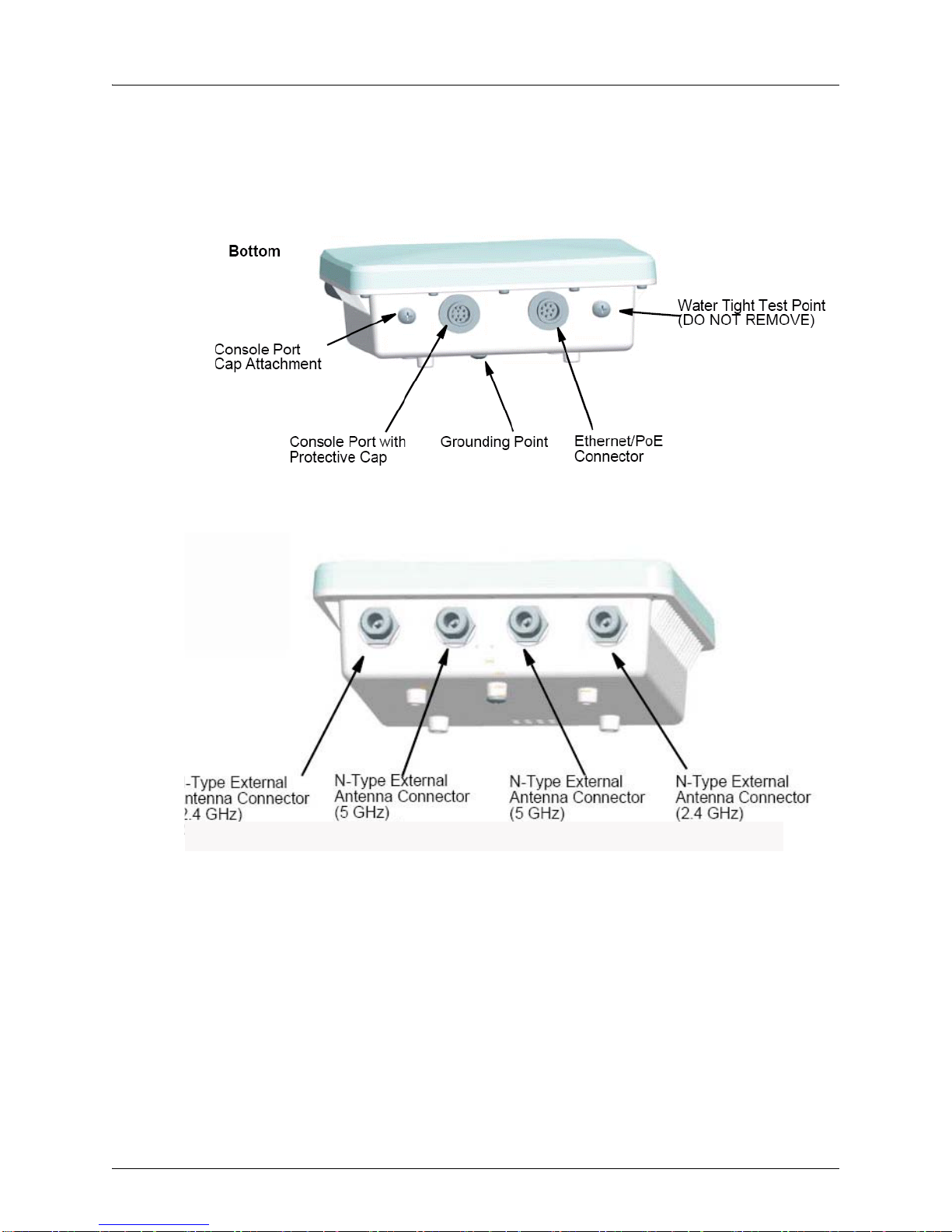
Water Tight Test Point . . . . . . . . . . . . . . . . . . . . . . . . . . . . . . . . . . . . . . . . . . . . . . . . . . . . 1-11
Wall- and Pole-Mounting Bracket Kits . . . . . . . . . . . . . . . . . . . . . . . . . . . . . . . . . . . . . . . . 1-11
Lightning Protector for Outdoor Antenna . . . . . . . . . . . . . . . . . . . . . . . . . . . . . . . . . . . . . . 1-11
System Configuration . . . . . . . . . . . . . . . . . . . . . . . . . . . . . . . . . . . . . . . . . . . . . . . . . . . . . .1-11
Features and Benefits . . . . . . . . . . . . . . . . . . . . . . . . . . . . . . . . . . . . . . . . . . . . . . . . . . . . . .1-11
External Hardware Features for the WLA632 . . . . . . . . . . . . . . . . . . . . . . . . . . . . . . . . . . . . 1-13
External Antenna Options. . . . . . . . . . . . . . . . . . . . . . . . . . . . . . . . . . . . . . . . . . . . . . . . . . 1-14
Multiple External Antenna Support. . . . . . . . . . . . . . . . . . . . . . . . . . . . . . . . . . . . . . . . . . . 1-15
High Power Mode . . . . . . . . . . . . . . . . . . . . . . . . . . . . . . . . . . . . . . . . . . . . . . . . . . . . . . . . 1-15
Ethernet . . . . . . . . . . . . . . . . . . . . . . . . . . . . . . . . . . . . . . . . . . . . . . . . . . . . . . . . . . . . . . .1-15
Features and Benefits . . . . . . . . . . . . . . . . . . . . . . . . . . . . . . . . . . . . . . . . . . . . . . . . . . . . . .1-16
Chapter 2 WLA Series Network Configurations
Infrastructure Configuration. . . . . . . . . . . . . . . . . . . . . . . . . . . . . . . . . . . . . . . . . . . . . . . . . . .2-1
WLAN Mesh Configuration . . . . . . . . . . . . . . . . . . . . . . . . . . . . . . . . . . . . . . . . . . . . . . . . . . . 2-2
Wireless Bridge Configuration. . . . . . . . . . . . . . . . . . . . . . . . . . . . . . . . . . . . . . . . . . . . . . . . . 2-3
i

Table of Contents
Chapter 3 Installing and Connecting an Access Point
Installation Requirements and Recommendations . . . . . . . . . . . . . . . . . . . . . . . . . . . . . . . . . 3-1
RingMaster Network Plan and Work Orders. . . . . . . . . . . . . . . . . . . . . . . . . . . . . . . . . . . . .3-1
WLC Appliance Recommendation . . . . . . . . . . . . . . . . . . . . . . . . . . . . . . . . . . . . . . . . . . . . 3-1
Weather Conditions . . . . . . . . . . . . . . . . . . . . . . . . . . . . . . . . . . . . . . . . . . . . . . . . . . . . . . .3-1
Ethernet Cabling. . . . . . . . . . . . . . . . . . . . . . . . . . . . . . . . . . . . . . . . . . . . . . . . . . . . . . . . . . 3-2
Grounding. . . . . . . . . . . . . . . . . . . . . . . . . . . . . . . . . . . . . . . . . . . . . . . . . . . . . . . . . . . . . . . 3-2
WLA Radio Safety Advisories. . . . . . . . . . . . . . . . . . . . . . . . . . . . . . . . . . . . . . . . . . . . . . . . 3-3
Installing an WLA620. . . . . . . . . . . . . . . . . . . . . . . . . . . . . . . . . . . . . . . . . . . . . . . . . . . . . . . .3-3
Mounting the Unit . . . . . . . . . . . . . . . . . . . . . . . . . . . . . . . . . . . . . . . . . . . . . . . . . . . . . . . . . 3-3
Connecting External Antennas . . . . . . . . . . . . . . . . . . . . . . . . . . . . . . . . . . . . . . . . . . . . . . . 3-5
Connecting Cables to the Unit . . . . . . . . . . . . . . . . . . . . . . . . . . . . . . . . . . . . . . . . . . . . . . .3-7
Connecting the Outdoor Power Supply. . . . . . . . . . . . . . . . . . . . . . . . . . . . . . . . . . . . . . . . .3-7
Connecting a WLA to a WLC . . . . . . . . . . . . . . . . . . . . . . . . . . . . . . . . . . . . . . . . . . . . . . . . 3-7
Aligning Antennas for Bridge or Mesh Links. . . . . . . . . . . . . . . . . . . . . . . . . . . . . . . . . . . . . 3-8
Installing an WLA622. . . . . . . . . . . . . . . . . . . . . . . . . . . . . . . . . . . . . . . . . . . . . . . . . . . . . . .3-11
Mounting the Unit . . . . . . . . . . . . . . . . . . . . . . . . . . . . . . . . . . . . . . . . . . . . . . . . . . . . . . . .3-11
Connecting External Antennas . . . . . . . . . . . . . . . . . . . . . . . . . . . . . . . . . . . . . . . . . . . . . . 3-15
Connecting Cables to the Unit . . . . . . . . . . . . . . . . . . . . . . . . . . . . . . . . . . . . . . . . . . . . . .3-17
Connecting the Outdoor Power Supply. . . . . . . . . . . . . . . . . . . . . . . . . . . . . . . . . . . . . . . .3-18
Connecting the Power Injector . . . . . . . . . . . . . . . . . . . . . . . . . . . . . . . . . . . . . . . . . . . . . .3-18
Checking the LED Indicators . . . . . . . . . . . . . . . . . . . . . . . . . . . . . . . . . . . . . . . . . . . . . . . 3-19
Connecting a WLA to a WLC . . . . . . . . . . . . . . . . . . . . . . . . . . . . . . . . . . . . . . . . . . . . . . . 3-20
Aligning Antennas for Bridge or Mesh Links. . . . . . . . . . . . . . . . . . . . . . . . . . . . . . . . . . . . 3-22
Installing an WLA632. . . . . . . . . . . . . . . . . . . . . . . . . . . . . . . . . . . . . . . . . . . . . . . . . . . . . . .3-24
Mounting the Unit . . . . . . . . . . . . . . . . . . . . . . . . . . . . . . . . . . . . . . . . . . . . . . . . . . . . . . . .3-24
Connecting External Antennas . . . . . . . . . . . . . . . . . . . . . . . . . . . . . . . . . . . . . . . . . . . . . . 3-28
Multiple External Antenna Support . . . . . . . . . . . . . . . . . . . . . . . . . . . . . . . . . . . . . . . . . . . 3-29
High Power Mode . . . . . . . . . . . . . . . . . . . . . . . . . . . . . . . . . . . . . . . . . . . . . . . . . . . . . . . . 3-29
Ethernet . . . . . . . . . . . . . . . . . . . . . . . . . . . . . . . . . . . . . . . . . . . . . . . . . . . . . . . . . . . . . . .3-29
Connecting Cables to the Unit . . . . . . . . . . . . . . . . . . . . . . . . . . . . . . . . . . . . . . . . . . . . . .3-30
Connecting the Power Injector . . . . . . . . . . . . . . . . . . . . . . . . . . . . . . . . . . . . . . . . . . . . . .3-30
Connecting an WLA to an WLC . . . . . . . . . . . . . . . . . . . . . . . . . . . . . . . . . . . . . . . . . . . . . 3-32
Chapter 4 WLA Series Technical Specifications
Outdoor AP Mechanical and Compliance Specifications. . . . . . . . . . . . . . . . . . . . . . . . . . . . . 4-1
Federal Communication Commission Interference Statement . . . . . . . . . . . . . . . . . . . . . . . . 4-3
Industry Canada Statement. . . . . . . . . . . . . . . . . . . . . . . . . . . . . . . . . . . . . . . . . . . . . . . . . . . 4-4
MAC Addresses. . . . . . . . . . . . . . . . . . . . . . . . . . . . . . . . . . . . . . . . . . . . . . . . . . . . . . . . . . . .4-5
Antenna Specifications for WLA620 and WLA622. . . . . . . . . . . . . . . . . . . . . . . . . . . . . . . . . .4-5
8 dBi Omnidirectional (2.4 GHz). . . . . . . . . . . . . . . . . . . . . . . . . . . . . . . . . . . . . . . . . . . . . .4-5
8 dBi Omnidirectional (5 GHz) . . . . . . . . . . . . . . . . . . . . . . . . . . . . . . . . . . . . . . . . . . . . . . .4-6
13.5 dBi 120-Degree Sector . . . . . . . . . . . . . . . . . . . . . . . . . . . . . . . . . . . . . . . . . . . . . . . . . 4-7
10 dBi 120-Degree Sector . . . . . . . . . . . . . . . . . . . . . . . . . . . . . . . . . . . . . . . . . . . . . . . . . . 4-8
18 dBi 18-Degree Panel . . . . . . . . . . . . . . . . . . . . . . . . . . . . . . . . . . . . . . . . . . . . . . . . . . . .4-9
Signal Loss from Lightning Protector and Coaxial Cable . . . . . . . . . . . . . . . . . . . . . . . . . . .4-9
ii

Antenna Specifications for WLA632 . . . . . . . . . . . . . . . . . . . . . . . . . . . . . . . . . . . . . . . . . . 4-10
High-Power Mode. . . . . . . . . . . . . . . . . . . . . . . . . . . . . . . . . . . . . . . . . . . . . . . . . . . . . . . . 4-11
Supported Antennas. . . . . . . . . . . . . . . . . . . . . . . . . . . . . . . . . . . . . . . . . . . . . . . . . . . . . . 4-12
WLA632 Mechanical and Compliance Specifications. . . . . . . . . . . . . . . . . . . . . . . . . . . . . 4-12
RSSI Meter Functionality . . . . . . . . . . . . . . . . . . . . . . . . . . . . . . . . . . . . . . . . . . . . . . . . . . 4-12
Chapter 5 Cables and Pinouts
Twisted-Pair Cable Assignments for the WLA620 and WLA622. . . . . . . . . . . . . . . . . . . . . . . 5-1
10/100BASE-TX Pin Assignments . . . . . . . . . . . . . . . . . . . . . . . . . . . . . . . . . . . . . . . . . . . . 5-1
Straight-Through Wiring . . . . . . . . . . . . . . . . . . . . . . . . . . . . . . . . . . . . . . . . . . . . . . . . . . . . 5-2
Crossover Wiring . . . . . . . . . . . . . . . . . . . . . . . . . . . . . . . . . . . . . . . . . . . . . . . . . . . . . . . . . 5-2
8-Pin DIN Connector Pinout for the WLA620 and WLA622. . . . . . . . . . . . . . . . . . . . . . . . . . . 5-3
8-Pin DIN to RJ-45 Cable Wiring . . . . . . . . . . . . . . . . . . . . . . . . . . . . . . . . . . . . . . . . . . . . . 5-3
WLA632 External Connectors . . . . . . . . . . . . . . . . . . . . . . . . . . . . . . . . . . . . . . . . . . . . . . . . . 5-4
Ethernet . . . . . . . . . . . . . . . . . . . . . . . . . . . . . . . . . . . . . . . . . . . . . . . . . . . . . . . . . . . . . . . .5-4
Chapter 6 Wireless Bridge Link Planning
Radio Path Planning . . . . . . . . . . . . . . . . . . . . . . . . . . . . . . . . . . . . . . . . . . . . . . . . . . . . . . . . 6-1
Antenna Height. . . . . . . . . . . . . . . . . . . . . . . . . . . . . . . . . . . . . . . . . . . . . . . . . . . . . . . . . . . 6-2
Radio Interference . . . . . . . . . . . . . . . . . . . . . . . . . . . . . . . . . . . . . . . . . . . . . . . . . . . . . . . .6-3
Weather Conditions . . . . . . . . . . . . . . . . . . . . . . . . . . . . . . . . . . . . . . . . . . . . . . . . . . . . . . .6-3
Ethernet Cabling. . . . . . . . . . . . . . . . . . . . . . . . . . . . . . . . . . . . . . . . . . . . . . . . . . . . . . . . . . 6-4
Grounding. . . . . . . . . . . . . . . . . . . . . . . . . . . . . . . . . . . . . . . . . . . . . . . . . . . . . . . . . . . . . . . 6-5
WLA622 Antenna Position and Orientation . . . . . . . . . . . . . . . . . . . . . . . . . . . . . . . . . . . . . 6-5
WLA Radio Safety Advisories. . . . . . . . . . . . . . . . . . . . . . . . . . . . . . . . . . . . . . . . . . . . . . . . 6-5
iii

Table of Contents
iv

WLA620, WLA622 and WLA632
Overview
A Juniper Networks model WLA620 provides IEEE 802.11 wireless access to the network.
WLAs are designed for use with a Juniper Networks WLAN controller. WLAs require
hardware installation only. All configuration for an WLA is performed on the WLC.
Warning: Installation must be performed by qualified service personnel only. Read and
follow all warning notices and instructions marked on the product or included in the
documentation. Before installing the product, read the Regulatory Guide document.
Informational Note: The WLA radios are disabled by default and can be enabled only by
a system administrator using the WLC.
Hardware Overview
WLA620
The WLA620 provides wireless access point services for clients in the local LAN ar ea,
and can provide point-to-point or point-to-multipoint wireless bridge links between
remote Ethernet LANs. The WLA is housed in a weatherproof enclosur e for mo untin g
outdoors and includes brackets for attaching to a wall, pole, radio mast, or tower
structure. The unit is powered through an Ethernet cable connection from a power
injector module installed indoors. The WLA620 provides a 54 Mbps half-duplex
connection for each active channel.
A wireless bridge system offers a solution for connectivity between remote Ethernet
wired LANs, or to provide Internet access to an isolated site where a wired link may be
difficult or expensive to deploy. The wireless bridge connection provides data rates of
up to 108 Mbps.
Radio Characteristics – The IEEE 802.11a and 802.11g standards use a radio
modulation technique known as Orthogonal Frequency Division Multiplexing (OFDM),
and a shared collision domain (CSMA/CA). The 802.11a standard operates in the 5
GHz Unlicensed National Information Inf ra str uc tu re (UNII ) ba nd , an d th e 80 2. 11g
standard in the 2.4 GHz band.
IEEE 802.11g includes backward compatibility with the IEEE 802.11b standard. IEEE
802.11b also operates at 2.4 GHz, but uses Direct Sequence Spread Spectrum
(DSSS) and Complementary Code Keying (CCK) modulation technology to achieve a
communication rate of up to 11 Mbps.
Copyright © 2012, Juniper Networks, Inc. 1

WLA620, WLA622 and WLA632 Overview
WLA622
The WLA622 provides only external antenna options and is designed to operate as the
“root bridge” in point-to-multipoint configurations, supporting wireless bridge
connections to as many as six units. The WLA is housed in a weatherproof enclosure
for mounting outdoors and includes brackets for att aching to a wall, pole, radi o mast, or
tower structure. The wireless bridge connection provides data rates of up to 54 Mbps. A
WLC cannot be used to power the outdoor WLA. The WLA requires a Juniper-designed
XPS power supply for proper operation.
WLA632
The WLA632 is a 802.11a/b/g/n WLA that is designed for pole-mounting and wall
mounting. The WLA632 supports 6 antenna ports, 3 for the 11a/n radio and 3 for the
11b/g/ n ra dio . A nt en na s ot he r than Juniper approved antennas are not supported. The
WLA632 does not support internal antennas or PoE. A WLC cannot be used to power
this WLA. A WLA-XPS9001GO power supply that uses the IP67 multi-pin DIN
connector is required. The WLA-XPS9001GO is specifically designed for the WLA632
and is available from Juniper Networks.
WLA-XPS9001GO Power Supply Unit
The WLA-XPS9001GO PSU has separate SKUs for North American and International
users.
WLA-XPS9001GO-NA— An outdoor 802.3at compliant, 100-240 VAC 50-60Hz input,
Gigabit PoE midspan PSU with a North American connector that ships with the
mounting bracket. This PSU and NA connector is intended for u se in countries following
North America Safety Standards.
WLA-XPS9001GO-INTL— An outdoor 802.3at compliant, 100-240 VAC 50-60Hz input,
Gigabit PoE midspan PSU with a International power cord. This PSU and international
power cord is intended for use in world-wide opera tio ns except countries following
North America Safety Standards.
Warning: The WLA632 must only be used with a Juniper Networks approved
WLA-XPS9001GO power supply in order to prevent possible damage to the unit. The
WLA-XPS9001GO power supply is intended for indoor and outdoor environments.
Package Checklist
The WLA620 package includes:
1 WLA620
1 Category 5 network cable, length 50 m (164 ft)
1 power injector module and power cord
Outdoor pole-mounting bracket kit
Installation manual
Optional: 2 N-type RF coaxial cables
Optional: Outdoor wall-mounting bracket kit
Optional: Lightning protector for outdoor antenna
The WLA622 package includes:
1 WLA622
WLA-XPS9001GO (packaged in a separate box)
2 Copyright © 2012, Juniper Networks, Inc.
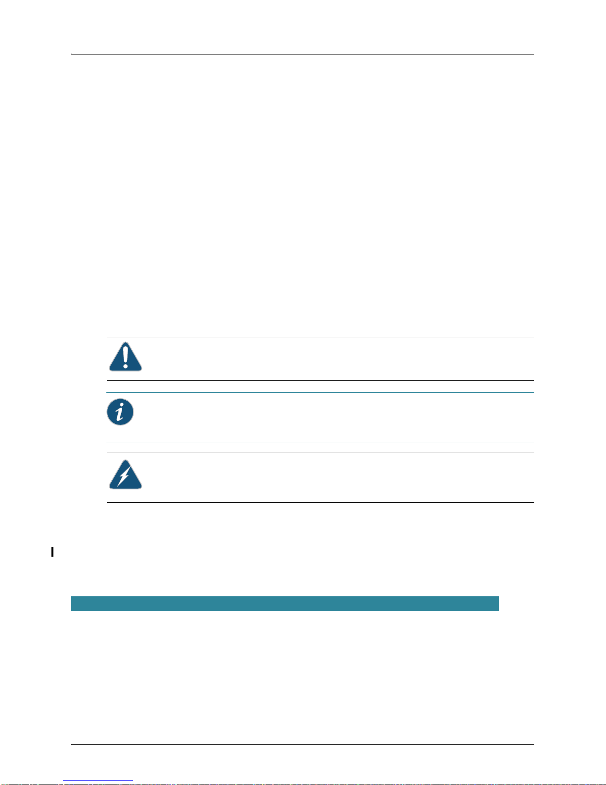
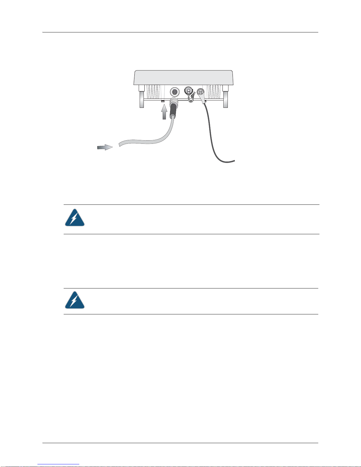
WLA620, WLA622 and WLA632 Overview
Ethernet Port
RSSI Connector
with Protective Cap
Grounding Point Screw
Installation manual
Optional: Lightning protector for outdoor antenna
The WLA632 package includes:
1 WLA632
Mounting brackets, split washers and mounting hardware
Weather sealing caps for all 6 external antenna connectors
Installation manual
1 WLA-XPS9001GO outdoor power supply.
Circular DIN to RJ45 dongle cable and waterproof caps for RJ45 dongle
Two-hole tabular lug for AWG #8 ground cable
Antenna connector terminator. Any unused antenna connector on an active radio
must be terminated.
Contact Juniper Networks if there are any incorrect, missing or damaged parts. If
possible, retain the carton, including the original packing materials. Use them again to
repack the product in case there is a need to return it.
External Hardware Features for the WLA620
Figure 1–1 and Figure 1–2 below show the external hardware features of the WLA620.
Figure 1–1. WLA Model WLA620—Bottom View
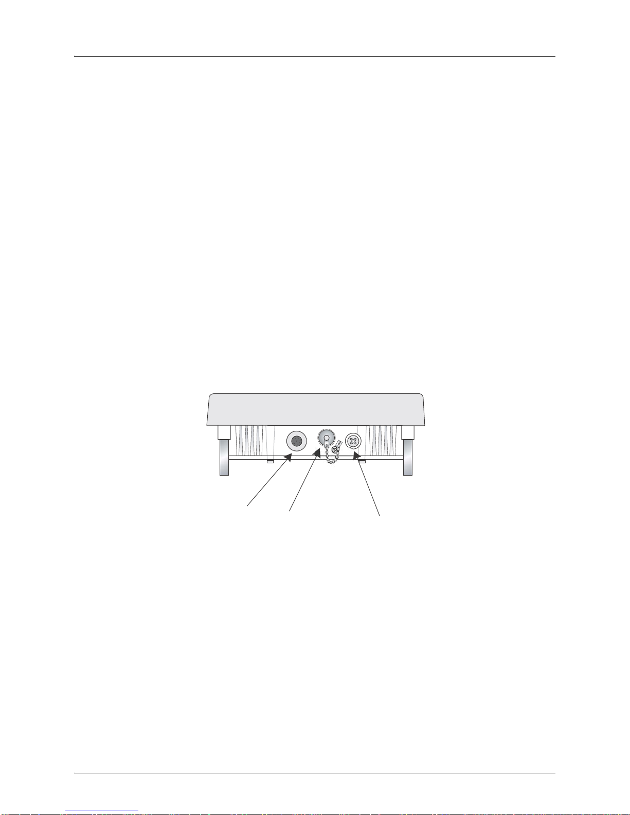
Figure 1–2. WLA Model WLA620—Top View
Copyright © 2012, Juniper Networks, Inc. 3
WLA620, WLA622 and WLA632 Overview
N-Type External
Antenna Connector
(2.4 GHz)
N-Type External
Antenna Connector
(5 GHz)
External Antenna Options
The WLA620 unit does not include an integra ted antenna, but provides various external
antenna options for both 5 GHz and 2.4 GHz operation. The WLA620 unit requires the
2.4 GHz 8 dBi omnidirectional external antenna for 2.4 GHz operation. The following
table summarizes the external antenna options:
Table 1: External Antenna Options
HPBW*
Antenna Type Gain (dBi)
5 GHz Omnidirectional 8 360 12 Linear, vertical
5 GHz 120-Degree Sector 13.5 120 6 Linear, vertical
5 GHz 18-Degree Panel 18 18 18 Linear, vertical
2.4 GHz 120-Degree Sector 10 120 15 Linear, vertical
2.4 GHz Omnidirectional 8 360 15 Linear, vertical
* Half-power beam width in degrees
Horizontal
HPBW*
Ver ti ca l
Polarization
External antennas connect to the N-type RF connectors on the WLA620 using the
provided coaxial cables.
Ethernet Port
The WLA620 has one 10BASE-T/100BASE-TX 8-pin DIN port that connects to the
power injector module using the included Ethernet cable. The Ethernet port connection
provides power to the WLA620 as well as a data link to the local network.
Informational Note: The power injector module does not support Power over Ethernet
(PoE) based on the IEEE 802.3af standard. The WLA620 must always be powered on by
being connected to the power injector module.
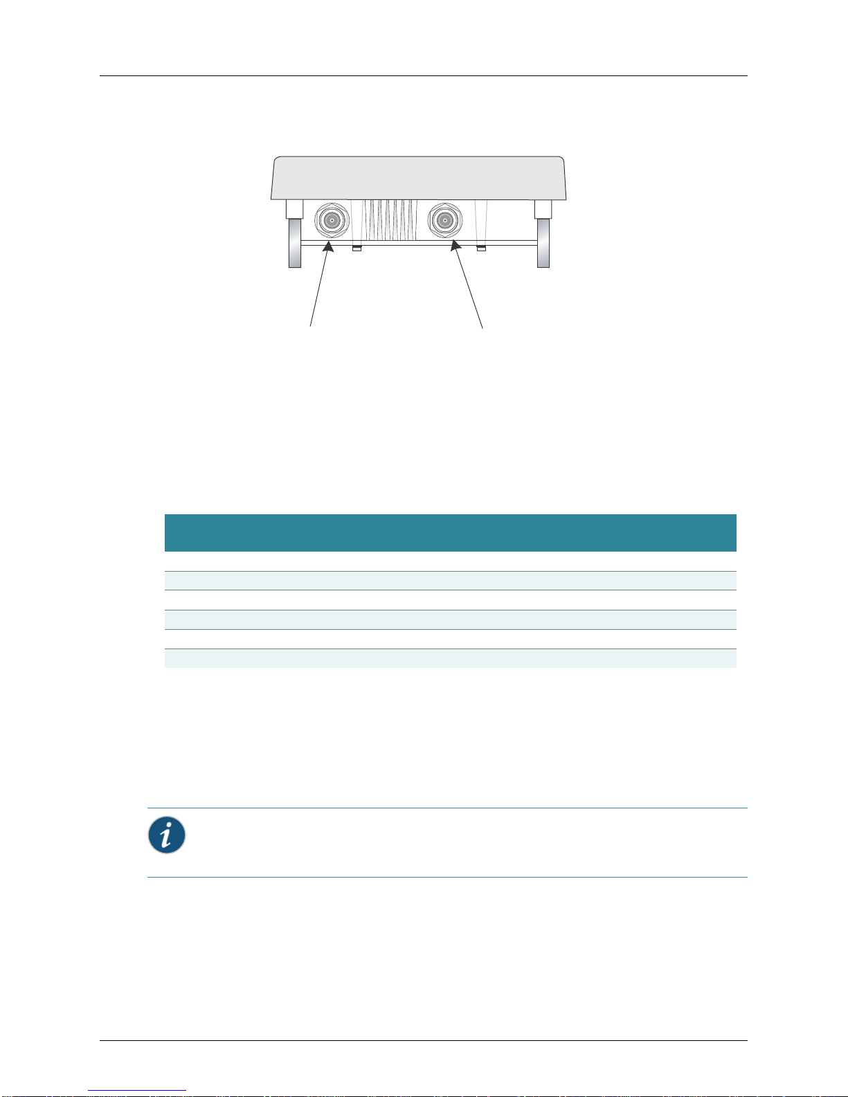
Power Injector Module
The WLA620 receives power through the network cable connection using
power-over-Ethernet technology. A power injector module is included in the WLA620
package and provides two RJ45 Ethernet ports, one for connec tin g to th e WLA620
(Output), and the other for connecting to a WLC switch or a local LAN switch (Input).
4 Copyright © 2012, Juniper Networks, Inc.
WLA620, WLA622 and WLA632 Overview
Input Output
LED Indicator
Ethernet from
Local Network
Ethernet and Power
to MP-620
AC Power Socket
(Hidden)
The Input port uses an MDI (i.e., internal straight-through) pin configuration. You can
therefore use straight-through twisted-pair cable to connect this port to most network
interconnection devices such as a switch or router that provide MDI-X ports. However,
when connecting the access point to a workstation or other device without MDI-X ports,
you must use crossover twisted-pair cable.
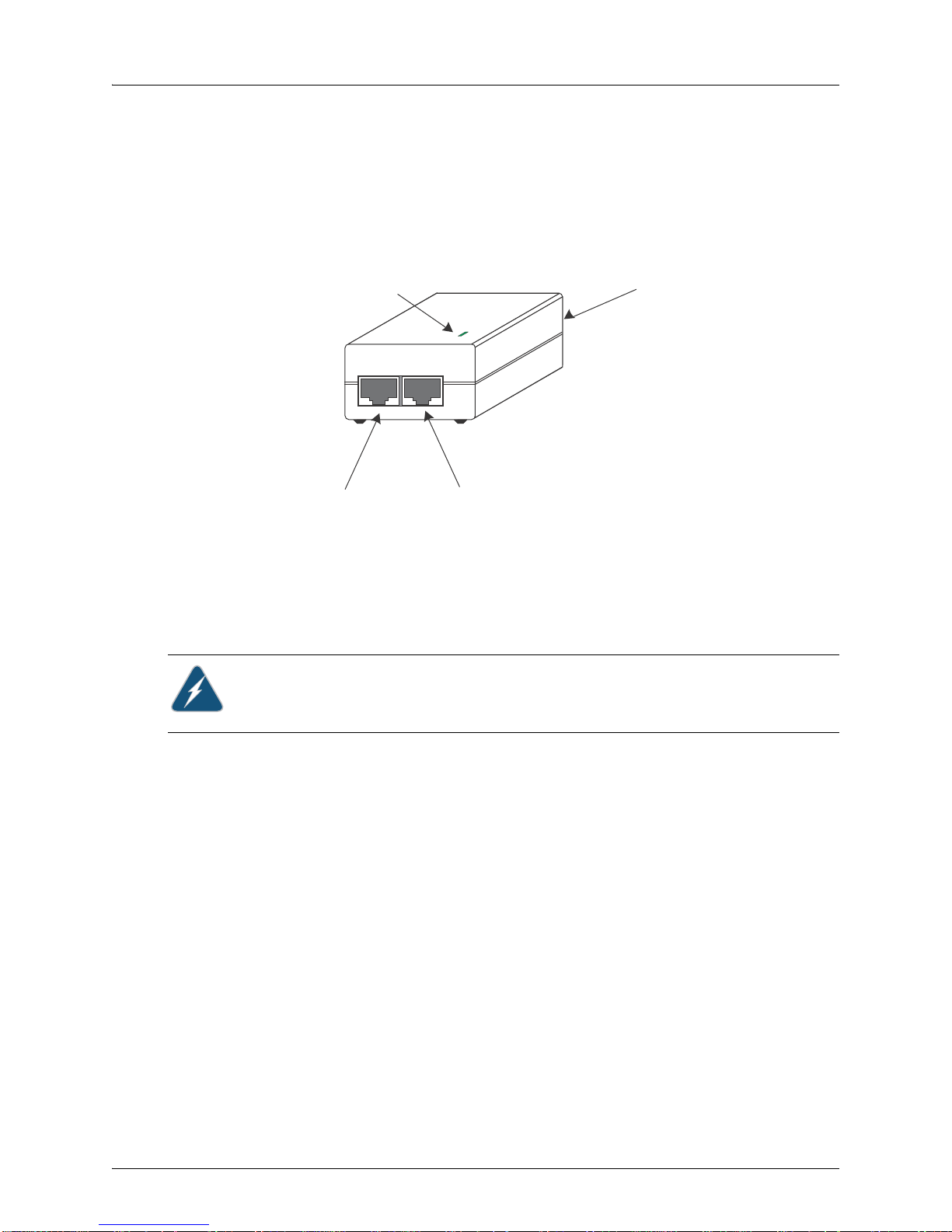
Figure 1–3. Power Injector Module
The WLA620 does not have a power switch. It is powered on when the Ethernet port is
connected to the power injector module, and the power injector module is connected to
an AC power source. The power injector includes one LED indicator tha t turns on when
AC power is applied.
The power injector module automatically adjusts to any AC voltage between 100-240
volts at 50 or 60 Hz. No voltage range settings are required.
Warning: The power injector module is designed for indoor use only. Never mount the
power injector outside with WLA620 unit.
Receive Signal Strength Indicator (RSSI) BNC Connector
The RSSI connector provides an output voltage that is proportio nal to the received radio
signal strength. A DC voltmeter can be connected the this port to assist in aligning the
antennas at both ends of a wireless bridge link.
Grounding Point
Even though the WLA620 includes a built-in lightning protection, it is important that the
unit is properly connected to ground. A grounding screw is provided for attaching a
ground wire to the unit.
Wall- and Pole-Mounting Bracket Kits
The WLA620 includes bracket kits that can be used to mount the unit to a wall, pole,
radio mast, or part of a tower structure.
Lightning Protector for Outdoor Antenna
Copyright © 2012, Juniper Networks, Inc. 5
If you are using the WLA620 with an outdoor antenna, Juniper Networks recommends
installing an external lightning protector for the antenna. An external lightning protector
may be obtained from Juniper Networks.
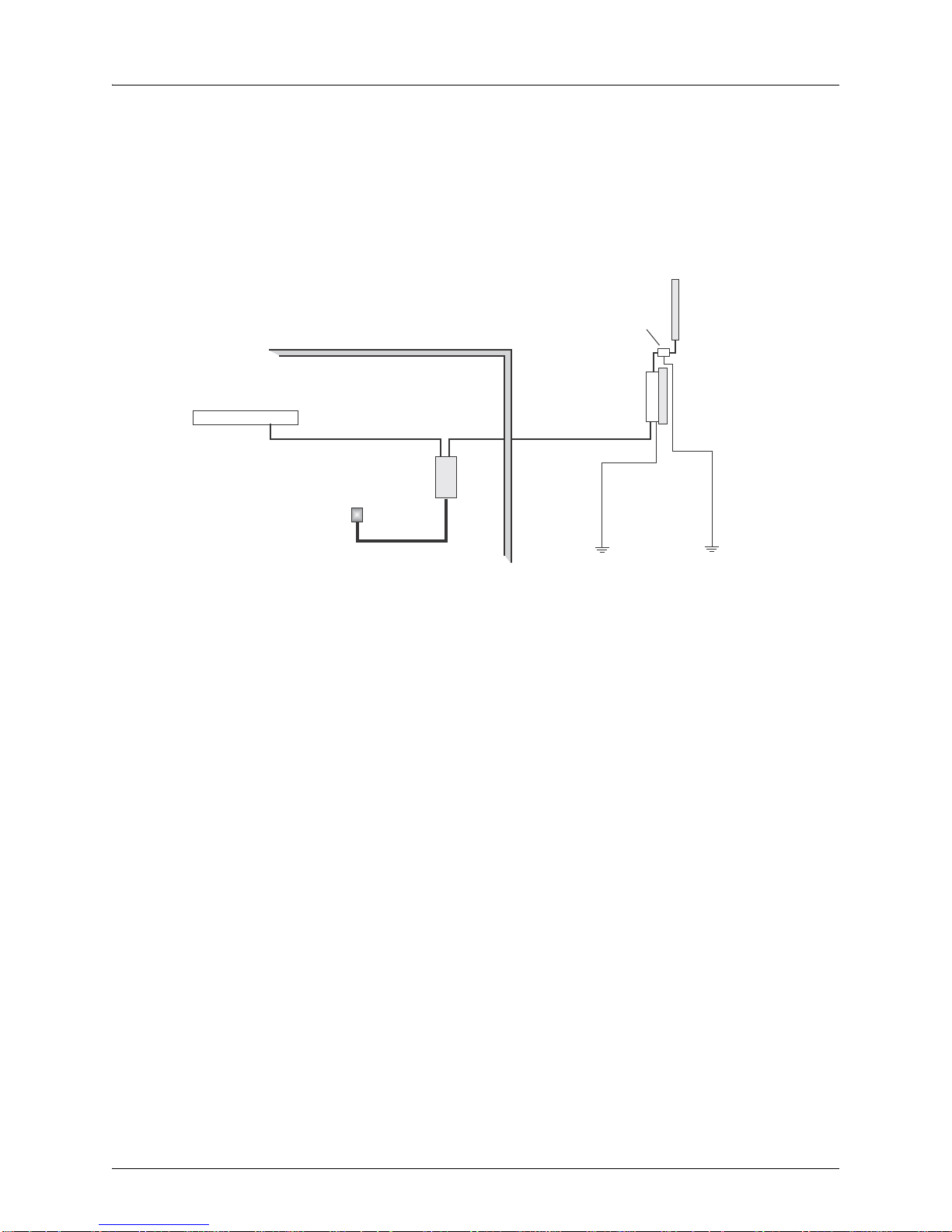
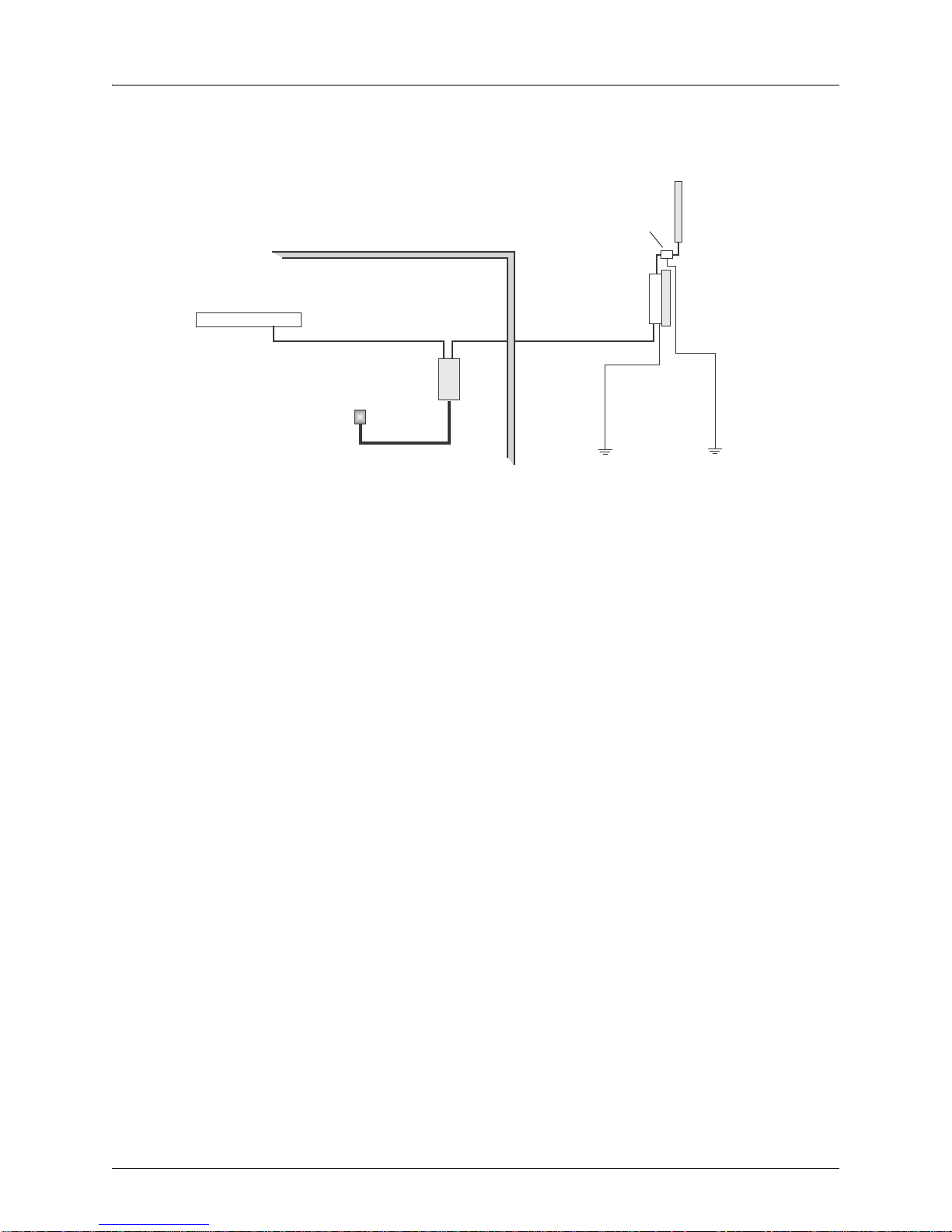
WLA620, WLA622 and WLA632 Overview
Indoor Outdoor
LAN Switch
AC Power
Power
Injector
WLA620 Unit
GroundWire
EthernetCable EthernetCable
E xternal A ntenna
RF C oaxial Cable
Lightning
Protector
System Configuration
At each location where an WLA620 unit is installed, it must be connected to the local
network using the power injector module. The following figure illustrates the system
component connections.
Features and Benefits
The WLA620 provides the following features and benefits:
The WLA620 supports access point services for the 5 GHz and 2.4 GHz radios using
various external antenna options
Maximum data rate up to 108 Mbps on the 802.11a (5 GHz) radio
Outdoor weatherproof design
IEEE 802.11a and 802.11b/g compliant
Local network connection via 10/100 Mbps Ethernet port
Powered through its Ethernet cable connection to the powe r inje cto r m odule
Includes wall- and pole-mount brackets
Security through 64/128/152-bit Wired Equivalent Protection (WEP) or 128-bit
Advanced Encryption Standard (AES) encryption
Scans all available channels and selects the b est channel and data rate based on the
signal-to-noise ratio
Figure 1–4. System Component Connections
6 Copyright © 2012, Juniper Networks, Inc.
WLA620, WLA622 and WLA632 Overview
Port 1
Port 2
Port 3 Port 4
External Hardware Features for the WLA622
Figure 1–5. MP Access Point Model WLA622—Bottom View
Figure 1–6. Access Point Model WLA622—Top View. Antenna ports are numbered
from the left 1 to 4.
Copyright © 2012, Juniper Networks, Inc. 7
WLA620, WLA622 and WLA632 Overview
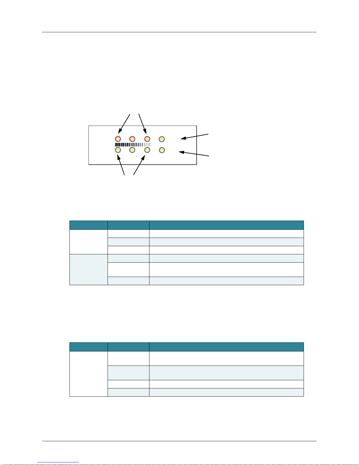
Power
Link
11a
11b/g
Power
802.11a Wireless
Link/Activity
Ethernet
Link/Activity
802.11b/g Wireless
Link/Activity
LED Indicators
The LEDs are used for RSSI signal strength measurements to aim directional antennas
and to indicate the state of the WLA. The access point includes eight status LED
indicators, as shown below . The LEDs are viewed right to le f t as you look a t the ba ck of
the WLA.
The table below describes the system status LEDs.
Table 2: External Antenna Options
LED Status Description
Power Green Indicates that the system is working normally.
Amber Indicates a system reset.
Off The bridge is not receiving power or there is a fault with the power supply.
Link Green Indicates a valid 10/100 Mbps Ethernet cable link with no activity.
Flashing Green Indicates that the access point is transmitting or receiving data on a
10/100 Mbps Ethernet LAN. Flashing rate is proportional to network activity.
Off No link is present or the Ethernet LAN port is disabled.
The 1 1 a and 11b/g LEDs operate in two display modes, which are configurable through
the management interface. The RSSI mode is for aligning antennas in a b ridge link. The
WLA mode is for indicating data traffic rates.
The table below describes the wireless status LEDs in WLA mode.
Table 3: Wireless Status LEDs in WLA Mode
LED Status Description
11a (three LEDs) Slow Flashing
Green
Fast Flashing
Green
Green Indicates a high level of network activity.
Off No signal detected or the 802.11a radio is disabled.
The 802.11a radio is enabled with a low level of network activity.
Indicates a medium level of network activity.
8 Copyright © 2012, Juniper Networks, Inc.
Table 3: Wireless Status LEDs in WLA Mode
LED Status Description
11b/g
(three LEDs)
Slow Flashing
Amber
Fast Flashing
Amber
Off No signal detected or the 802.11b/g radio is disabled.
The 802.11b/g radio is enabled with a low level of network activity.
Indicates a medium level of network activity.
The table below describes the wireless status LEDs in RSSI mode.
Table 4: Wireless Status LEDs in RSSI Mode
LED Status Description
11a
(three LEDs)
11b/g
(three LEDs)
Off No signal detected or the 802.11a radio is disabled.
Slow Flashing
Green
Fast Flashing
Green
On Green Indicates a high level signal.
Off No signal detected or the 802.11b/g radio is disabled.
Slow Flashing
Green
Fast Flashing
Green
The 802.11a radio is enabled with a low level signal.
Indicates a medium level signal.
The 802.11b/g radio is enabled with a low level signal.
Indicates a medium level signal.
WLA620, WLA622 and WLA632 Overview
External Antenna Options
The WLA622 supports one or two antennas per radio. If there are two antennas
connected to the radio then antenna diversity is used to send all traffic types. If there is
one antenna then proper operations of antenna diversity may be affected.
By default there is one external antenna so there will be no use of antenna diversity for
WLAs with external antennas defined. The setting below is applied per radio so you can
have one radio indoors and one radio outdoors.
set ap num radio num external-antennas num
Informational Note: This is a new command, and it is only supported in MSS 7.1 or higher.
Caution: The splitting of antennas on a single radio between indoors and outdoors is not
allowed.
The WLA622 supports one or two antennas per radio. If there are two antennas they
must be the same antenna model. A single antenna will always be connected to the
connector 1 for 2.4 GHz and connector 3 for 5Ghz.
Copyright © 2012, Juniper Networks, Inc. 9

WLA620, WLA622 and WLA632 Overview
The WLA622 supports four antenna ports, two for the 11a radio and two for the 11bg
radio. The supported antennas models are:
802.11bg Radio
ANT-1120-OUT
ANT-1360-OUT
802.11a Radio
ANT-5120-OUT
ANT-5360-OUT
ANT-5PNL-OUT (for single antenna only for use on port 3)
External antennas connect to the N-type RF connectors on the wireless bridg e either
directly or using coaxial cables.
Ethernet Port
The wireless bridge has one 10BASE-T/100BASE-TX 8-pin DIN port that connects to
the power injector module using the included Ethernet cable. The Ethernet port
connection provides power to the wireless bridge as well as a data link to the local
network.
The wireless bridge appears as an Ethernet node and performs a bridging function by
moving packets from the wired LAN to the remote end of the wireless bridge link.
Informational Note: The power injector module does not support Power over Ethernet
(PoE) based on the IEEE 802.3af standard. The wireless bridge unit must always be
powered on by being connected to the power injector module.
Power Injector Module
The WLA622 receives power through the network cable connection using
Power-over-Ethernet (PoE) technology. An outdoor power injector module is available
seperately and provides two RJ45 Etherne t ports, one for conn ecting to the WLA622
(PoE Output), and the other for connecting to an WLC or a local LAN switch Data
(Input).
The Input port uses an MDI (i.e., internal straight-through) pin configuration. You can
therefore use straight-through twisted-pair cable to connect this port to most network
interconnection devices such as a switch or router that provide MDI-X ports. However,
when connecting the access point to a workstation or other device without MDI-X ports,
you must use crossover twisted-pair cable.
10 Copyright © 2012, Juniper Networks, Inc.
WLA620, WLA622 and WLA632 Overview
Ground Wire
Ethernet Cabl e
To MP-622
Figure 1–7. Power Injector Module
The WLA622 does not have a power switch. It is powered on when the Ethernet port is
connected to the power injector module, and the power injector module is connected to
an AC power source.
The power injector module automatically adjusts to any AC voltage between 100-240
volts at 50 or 60 Hz. No voltage range settings are required.
Caution: The power injector module is designed for indoor use.
Grounding Point
In order for the WLA622 includes a built-in lightning protector to work properly, the unit
must be properly connected to ground. A grounding screw is provided for attaching a
ground wire to the unit.
Water Tight Test Point
Caution: Do not remove or loosen this screw. If you do, you can damage the unit.
Wall- and Pole-Mounting Bracket Kits
The WLA622 includes bracket kits that can be used to mount the unit to a wall, pole,
radio mast, or part of a tower structure.
Lightning Protector for Outdoor Antenna
If you are using the WLA622 with an outdoor antenna, Juniper Networks strongly
recommends installing an external lightning protector for the antenna. An external
lightning protector may be obtained from Juniper Networks.
System Configuration
At each location where an WLA622 unit is installed, it must be connected to the local
network using the power injector module. The following figure illustrates the system
component connections.
Copyright © 2012, Juniper Networks, Inc. 11
WLA620, WLA622 and WLA632 Overview
LAN Switch
Indoor Out
door
AC Power
Power
Injector
WLA622 Unit
Ground Wire
Ethernet Cable Ethernet Cable
External Antenna
RF Coaxial Cable
Lightning
Protector
Figure 1–8. System Component Connections
Features and Benefits
The WLA622 provides the following features and benefits:
The WLA622 supports access point services for the 5 GHz and 2.4 GHz radios using
various external antenna options
WLA622 units support 5 GHz point-to-multipoint links using various external
Juniper-supplied antenna options
Maximum data rate up to 54 Mbps on the 802 .11a (5 GHz) radio
Outdoor weatherproof design
IEEE 802.11a and 802.11b/g compliant
Local network connection via 10/100 Mbps Ethernet port
Powered through its Ethernet cable connection to the powe r inje cto r m odule
Includes wall- and pole-mount brackets
Security through 64/128/152-bit Wired Equivalent Protection (WEP) or 128-bit
Advanced Encryption Standard (AES) encryption
Scans all available channels and selects the b est channel and data rate based on the
signal-to-noise ratio.
Manageable through an easy-to-use web-browser interface, command line (via Telnet),
or SNMP network management tool.
12 Copyright © 2012, Juniper Networks, Inc.
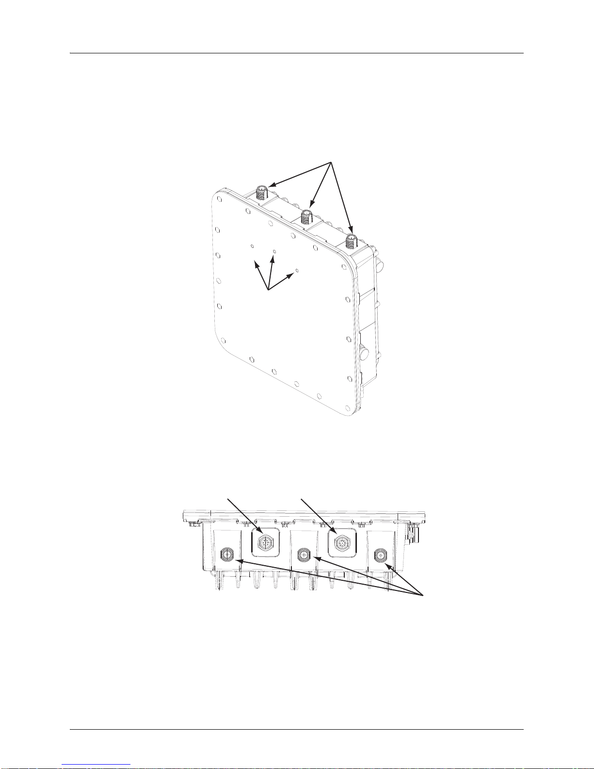
WLA620, WLA622 and WLA632 Overview
2.4GHz
Antenna Ports
LEDs
5GHz
Antenna Ports
Power
Ethernet Port
External Hardware Features for the WLA632
Copyright © 2012, Juniper Networks, Inc. 13
WLA620, WLA622 and WLA632 Overview
Informational Note: Two separate cables are required for power and ethernet function
on the WLA632. Both the cable dongles are RJ45 on one end, but one cable is specific to
power and one is specific to data. If the RJ45 cable ends are swapped, the unit will not
power up but will not be damaged. If the RJ45 cable ends are correctly inserted, the unit
will function normally.
LED Indicators
The WLA632 has LEDs that provide status information for the device. The table below
lists the function of the LEDs.
Table 5: WLA632 LED Functions
LED Status Description
Health Solid green All the following are true:
Solid amber WLA is waiting to receive boot instructions and a configuration file from an
Alternating green
and amber
Radio 1 /Radio 2 Solid green A client is associated with the radio.
Blinking green Associated client is sending or receiving traffic.
Blinking amber Non-associated client is sending or receiving traffic.
Alternating green
and amber
Unlit Means one of the following:
Management link with an WLC is operational.
WLA has booted.
WLA has received a valid configuration from an WLC.
At least one radio is enabled or is in sentry mode.
WLC.
WLA is booting and receiving a configuration file from an WLC.
After the MP boots and receives a configuration, this LED appearance
persists until a radio is enabled or is placed in sentry mode.
Radio is unable to transmit. This state can occur due to any of the following:
Excessive radio interference in the environment is preventing the radio
from sending beacons.
DFS has detected radar and is restricting traffic.
The radio has failed.
Radio is disabled and active scan is enabled. (The radio is in sentry
mode.)
Radio is enabled, but no clients are associated with it.
External Antenna Options
The WLA632 supports six antenna ports, 3 for the 11a/n radio and 3 for the 11b/g/n
radio. The 3 802.11 b/g/n antenna ports are on the top of the WL A an d a re nu mbe re d 1
to 3 from left to right. The 3 802.11a/b/g/n antenna ports are on the bottom of the WLA
with the ethernet and power ports. The antenna ports are numbered 4 to 6 from left to
right with port 4 on the outside edge of the RJ45 ethernet port.
The supported antennas models are:
802.11bgn Radio
ANT-7360A-OUT (N-type female connector)
ANT-77555-OUT (3 RPSMA- male connector)
ANT-74520-OUT (3 RPSMA- male connector)
14 Copyright © 2012, Juniper Networks, Inc.
WLA620, WLA622 and WLA632 Overview
802.11an Radio
ANT-7360A-OUT (N-type female connector)
ANT-74520-OUT (3 RPSMA- male connector)
ANT-77555-OUT (3 RPSMA- male connector)
ANT-5007-OUT (2-N-type connector)
The port usage depends on the antennas in use. If the OMNI antennas are used there
must be 3 antennas installed for the radio. If the ANT-5007-OUT antenna is used then
the two edge ports must be connected to the antenna (ports 4 and 6). The middle port
will be turned off by the software and should be terminated. If either the ANT-77555 or
74520 are used all three connectors must be connected to the WLA for the correct
radio. (A RPSMA N-type adaptor is required.)
set ap apnum radio num antennatype {ANT-7360A-OUT | ANT 77555-OUT | ANT
74520-OUT | ANT-5007-OUT} …
The antenna-location must be either indoors or outdoors. Although this is an outdoor
WLA it may be used indoors.
set ap apnum radio # antenna-location {indoors | outdoors}
Informational Note: Splitting the antennas between indoors and outdoors on the same
radio band is not allowed.
Multiple External Antenna Support
The WLA632 supports the use of multiple antenna ports per radio. Since there are
always multiple antennas connected, antenna diversity is always on. The command to
set the number of external antennas does not apply to the WLA632. The number of
antenna ports in use is determined by the antenna type.
set ap num radio num external-antennas num
If the ANT-5007-OUT antenna is in use on the 11a/n radio then the radio configuration
will revert to 2 x 3 mode rather than 3 x 3 mode and the middle port for the radio must
not be used.
Ethernet
The WLA632 supports a single IEEE 802.3-compliant auto-sensing 10/100/1000 BaseT
Ethernet interface on the Ethernet input connector. The WLA is configured as auto
MDI/MDIX. The WLA632 is powered from the WLA-XPS9001GO power supplies.
Caution: The WLA622 and WLA632 must only be used with a Juniper
Networks-approved WLA-XPS9001GO outdoor power supply in order to prevent possible
damage to the unit.
Caution: The 10/100 data port on the XPS is not used.
Copyright © 2012, Juniper Networks, Inc. 15

WLA620, WLA622 and WLA632 Overview
Caution: If you convert the 8 pin female circular DIN data port on the WLA632 bulkhead
to a standard RJ45 waterproof connection for the 10/100/1000 data port, PoE on the
10/100/1000 port must be disabled to prevent service interruption.The WLA632 does not
support PoE on the 10/100/1000 Ethernet data port.
Caution: Always add the waterproof cap to the RJ45 cable when installing the DIN-RJ45
dongle. Water can cause damage to the unit and the cables.
The WLA632 48VDC / Ethernet inputs provides primary and secondary lightning
protection up to 4KV on all conductors.
The Ethernet interface supports a cable length of up to 100m over CAT5e or CAT6
cable.
Grounding Point
Caution: Always ground the unit first with an appropriate grounding wire (not included)
by attaching it to the grounding screw on the unit.
The WLA632 has a two-hole grounding boss with threaded screws and washers for
direct electrical connection to earth ground. The two-hole tubular lug can be crimped
(standard crimp tool is required) on a AWG #8 copper wire for grounding.
Water Tight Test Point
Caution: Do not remove or loosen the pressure balance plug on the side of the unit. If you
do, you can damage the unit.
Wall- and Pole-Mounting Bracket Kits
The WLA632 includes bracket kits that can be used to mount the unit to a wall, pole,
radio mast, or part of a tower structure.
Lightning Protector for Outdoor Antenna
If you are using the WLA632 with an outdoor antenna, Juniper Networks strongly
recommends installing an external lightning protector for the antenna. An external
lightning protector may be obtained from Juniper Networks.
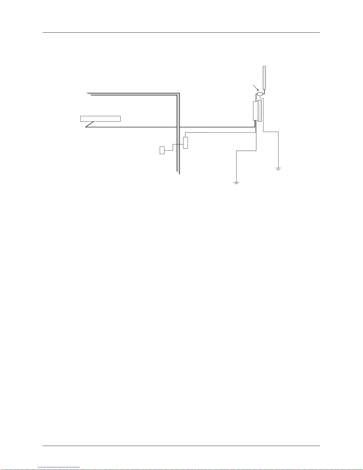
System Configuration
At each location where an WLA632 unit is installed, it must be connected to the local
network but the power injector is not required. The following figure illustrates the system
component connections.
16 Copyright © 2012, Juniper Networks, Inc.
WLA620, WLA622 and WLA632 Overview
LAN Switch
Indoor
Outdoor
WLA632
Ethernet Cable Ethernet Cable
External Antenna
RF Coaxial Cable
Lightning
Protector
Ground Wire
WLA-XPS9001GO
CAT-5 cabling
with appropriate
adapters
AC Power Outlet
Figure 1–9. System Component Connections
Features and Benefits
The WLA632 provides the following features and benefits:
802.11 a/b/g/n Features
High performance 11 Mbps (802.11b) or 54Mbps (802.11a/g) or 300Mbps(802.11n)
data rate
Wi-Fi, WPA interoperability ready
WPA/WPA2 with PSK/802.1x with TKIP/AES
40-bit and 128-bit WEP
Seamless roaming within the IEEE 802.11 a/b/g/n WLAN infrastructure.
Adjustable output power support
Interoperability with Juniper Networks Wireless Security Switch
Auto-sensing 10/100/1000 Ethernet port with auto MDI/MDI-X but has no PoE
support on the 10/100/100 (data) port
Comply with IEEE 802.3, 802.3u and 802.3ab
Powered by 30W/48Vdc outdoor AC/DC power supply.
Copyright © 2012, Juniper Networks, Inc. 17
 Loading...