Juniper Tunnel and Encryption Services Interfaces User Manual

Junos® OS

Tunnel and

r

Services Interfaces

User Guide for


Devices

Published

2021-04-18

ii

Juniper Networks, Inc. 1133 nn v n Way Sunnyvale, California 94089 USA

408-745-2000 www.juniper.net

Juniper Networks, the Juniper Networks logo, Juniper, and Junos are registered trademarks of Juniper Networks, Inc. in the United States and other countries. All other trademarks, service marks, registered marks, or registered service marks are the property of their r s c v owners.

Juniper Networks assumes no responsibility for any inaccuracies in this document. Juniper Networks reserves the right

to change, modify, transfer, or otherwise revise this b c

n without n

c

Junos® OS Tunnel and ncry

n Services Interfaces User Guide for R

n Devices

Copyright © 2021 Juniper Networks, Inc. All rights reserved.


The n rm

n in this document is current as of the date on the

page.

YEAR 2000 NOTICE

Juniper Networks hardware and s ftw r products are Year 2000 compliant. Junos OS has no known m r

m ns through the year 2038. However, the NTP c n is known to have some c y in the year 2036.

END USER LICENSE AGREEMENT

The Juniper Networks product that is the subject of this technical

c m n

n consists of (or is intended for use

with) Juniper Networks s ftw r

Use of such s

ftw r

is subject to the terms and c n

ns of the End User License

Agreement ("EULA") posted at

s s

r

n r n

s

r

. By downloading, installing or using such

s ftw r you agree to the terms and c n

ns of that EULA.


iii

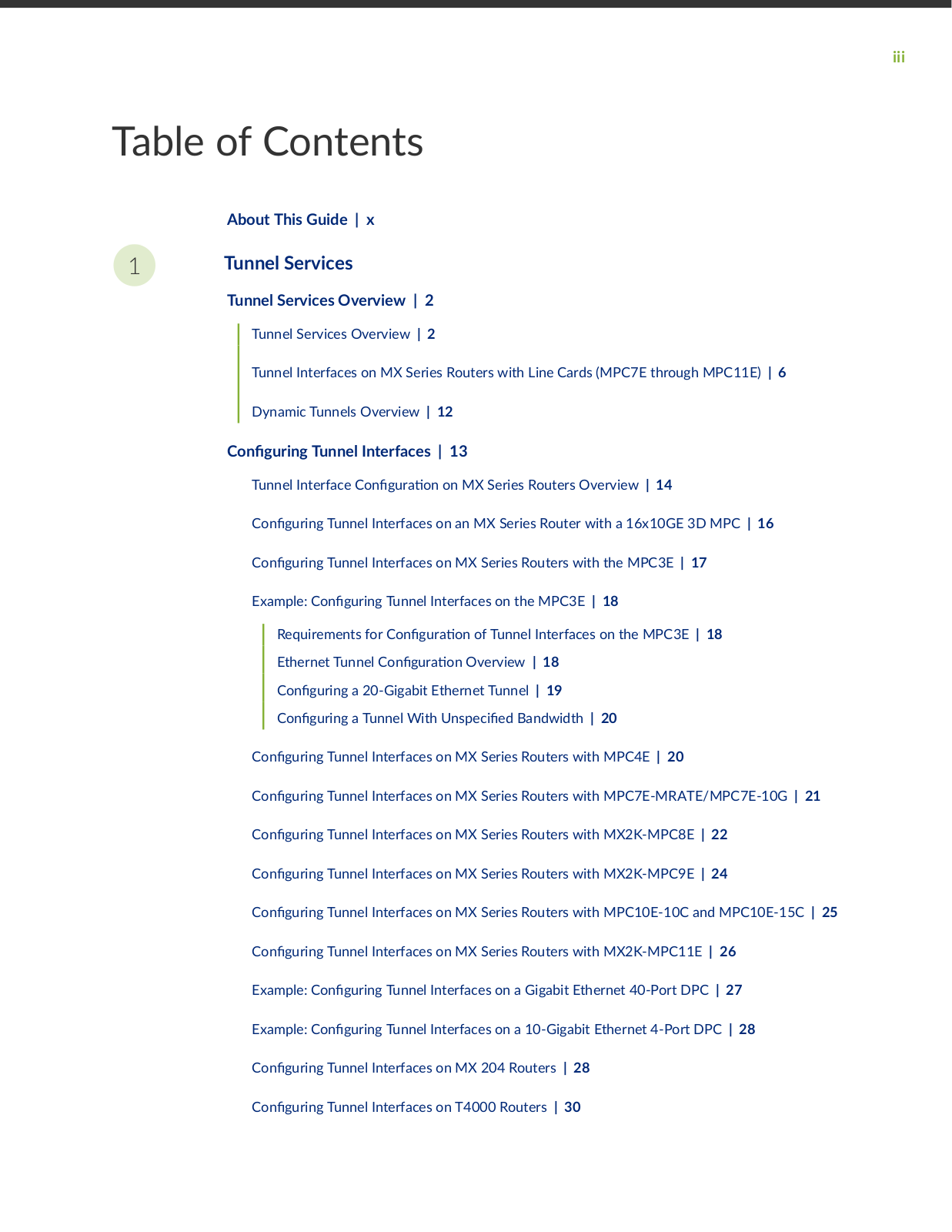
Table of Contents

About This Guide | x

1Tunnel Services

Tunnel Services Overview | 2


Tunnel Services Overview | 2


Tunnel Interfaces on MX Series Routers with Line Cards (MPC7E through MPC11E) | 6


Dynamic Tunnels Overview | 12


C n

r n Tunnel Interfaces | 13


Tunnel Interface C n

r

n on MX Series Routers Overview | 14


C n

r n

Tunnel Interfaces on an MX Series Router with a 16x10GE 3D MPC | 16


C n

r n

Tunnel Interfaces on MX Series Routers with the MPC3E | 17


Example: C n

r n

Tunnel Interfaces on the MPC3E | 18


Requirements for C n

r

n of Tunnel Interfaces on the MPC3E | 18


Ethernet Tunnel C n

r

n Overview | 18


C n

r n

a 20-Gigabit Ethernet Tunnel | 19


C n

r n

a Tunnel With

ns c

Bandwidth | 20


C n

r n

Tunnel Interfaces on MX Series Routers with MPC4E | 20


C n

r n

Tunnel Interfaces on MX Series Routers with MPC7E-MRATE/MPC7E-10G | 21


C n

r n

Tunnel Interfaces on MX Series Routers with MX2K-MPC8E | 22


C n

r n

Tunnel Interfaces on MX Series Routers with MX2K-MPC9E | 24


C n

r n

Tunnel Interfaces on MX Series Routers with MPC10E-10C and MPC10E-15C | 25


C n

r n

Tunnel Interfaces on MX Series Routers with MX2K-MPC11E | 26


Example: C

n

r n

Tunnel Interfaces on a Gigabit Ethernet 40-Port DPC | 27


Example: C

n

r n

Tunnel Interfaces on a 10-Gigabit Ethernet 4-Port DPC | 28


C n

r n

Tunnel Interfaces on MX 204 Routers | 28


C n

r n

Tunnel Interfaces on T4000 Routers | 30

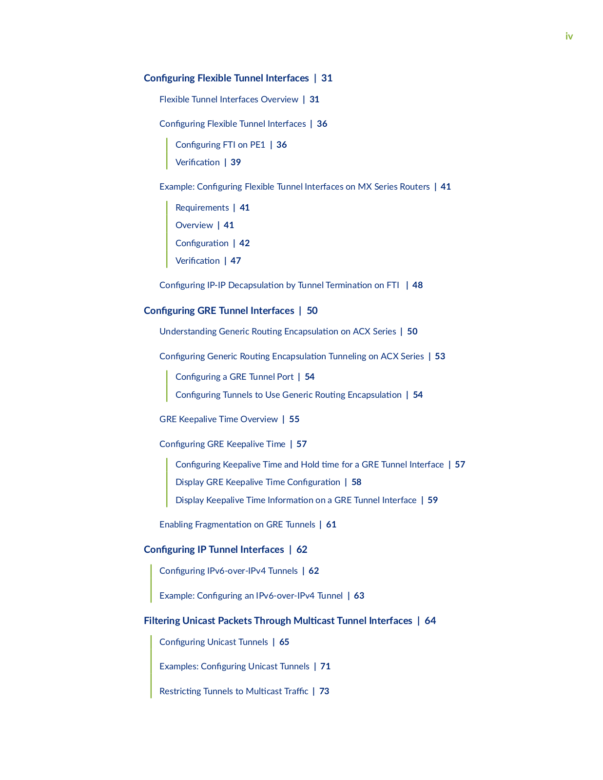
iv

C

n

r n

Flexible Tunnel Interfaces | 31


Flexible Tunnel Interfaces Overview | 31


C

n

r n

Flexible Tunnel Interfaces | 36


C n

r n

FTI on PE1 | 36


r

c

n | 39


Example: C

n

r n

Flexible Tunnel Interfaces on MX Series Routers | 41


Requirements | 41


Overview | 41


C n

r

n | 42


r

c

n | 47


C

n

r n

IP-IP c

s


n by Tunnel

rm n

n on FTI | 48

C

n

r n

GRE Tunnel Interfaces | 50


Understanding Generic R

n


nc

s

n on ACX Series | 50


C n

r n

Generic R

n

nc

s

n Tunneling on ACX Series | 53


C n

r n

a GRE Tunnel Port | 54


C n

r n

Tunnels to Use Generic R

n

nc

s

n | 54


GRE Keepalive Time Overview | 55


C n

r n

GRE Keepalive Time | 57


C n

r n

Keepalive Time and Hold m

for a GRE Tunnel Interface | 57


Display GRE Keepalive Time C n

r

n | 58


Display Keepalive Time n

rm

n on a GRE Tunnel Interface | 59


Enabling Fr

m n

n on GRE Tunnels | 61


C

n

r n

IP Tunnel Interfaces | 62


C

n

r n

IPv6-over-IPv4 Tunnels | 62


Example: C

n

r n

an IPv6-over-IPv4 Tunnel | 63


Filtering Unicast Packets Through

c s

Tunnel Interfaces | 64


C

n

r n

Unicast Tunnels | 65


Examples: C n

r n

Unicast Tunnels | 71


R s r c

n

Tunnels to M

c s

r

c | 73


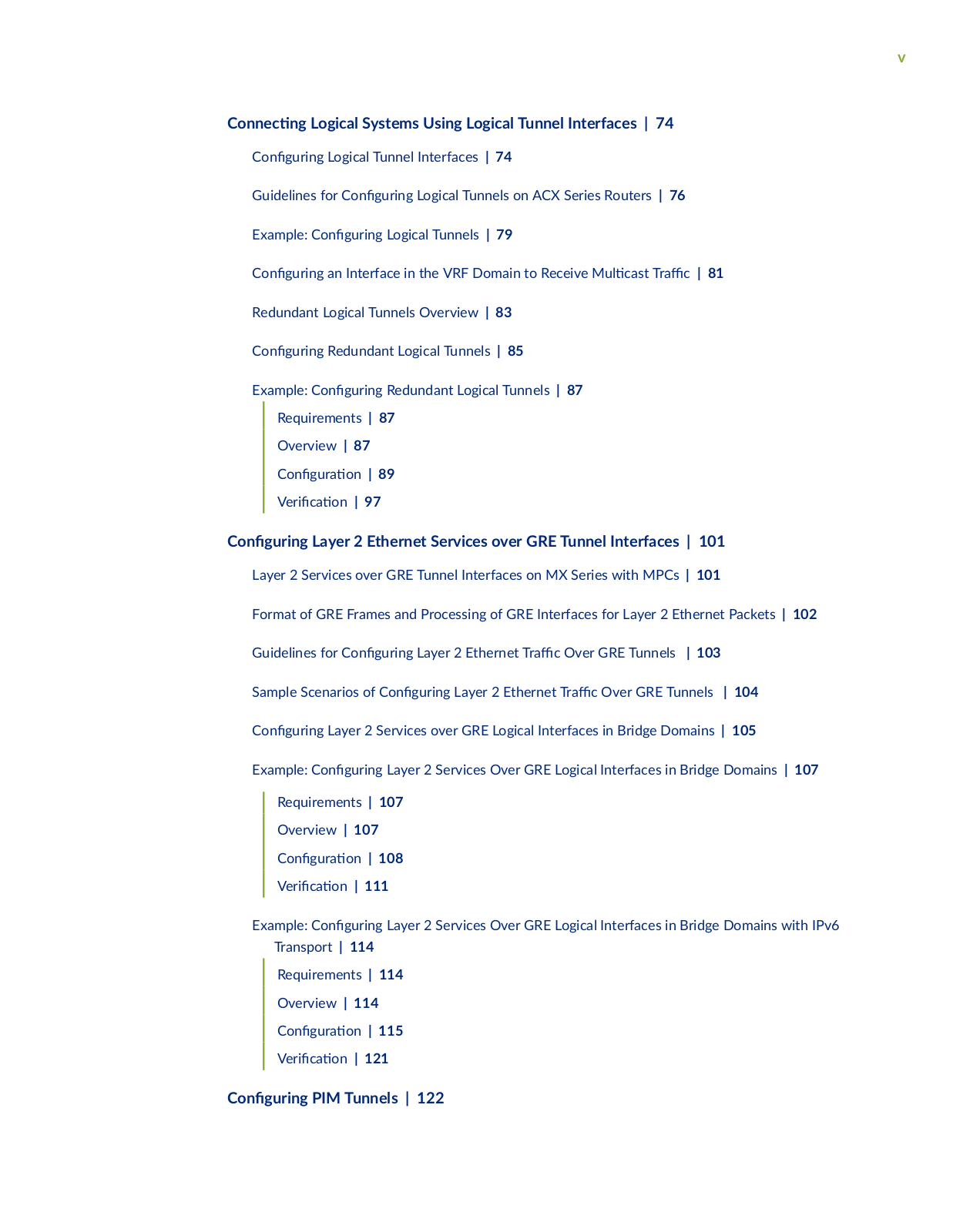
v

C

nn

c n

Logical Systems Using Logical Tunnel Interfaces | 74


C

n

r n

Logical Tunnel Interfaces | 74


Guidelines for C

n

r n

Logical Tunnels on ACX Series Routers | 76


Example: C

n

r n

Logical Tunnels | 79


C

n

r n

an Interface in the VRF Domain to Receive M c s r

c | 81


Redundant Logical Tunnels Overview | 83


C

n

r n

Redundant Logical Tunnels | 85


Example: C

n

r n

Redundant Logical Tunnels | 87


Requirements | 87


Overview | 87


C n

r

n | 89


r

c

n | 97


C

n

r n

Layer 2 Ethernet Services over GRE Tunnel Interfaces | 101


Layer 2 Services over GRE Tunnel Interfaces on MX Series with MPCs | 101


Format of GRE Frames and Processing of GRE Interfaces for Layer 2 Ethernet Packets | 102


Guidelines for C

n

r n

Layer 2 Ethernet r c Over GRE Tunnels

| 103


Sample Scenarios of C n

r n Layer 2 Ethernet r c Over GRE Tunnels | 104


C

n

r n

Layer 2 Services over GRE Logical Interfaces in Bridge Domains | 105


Example: C

n

r n

Layer 2 Services Over GRE Logical Interfaces in Bridge Domains | 107


Requirements | 107


Overview | 107


C n

r

n | 108


r

c

n | 111


Example: C

n

r n Layer 2 Services Over GRE Logical Interfaces in Bridge Domains with IPv6


Transport | 114


Requirements | 114


Overview | 114


C n

r

n | 115


r

c

n | 121


C n r n PIM Tunnels | 122

2

3

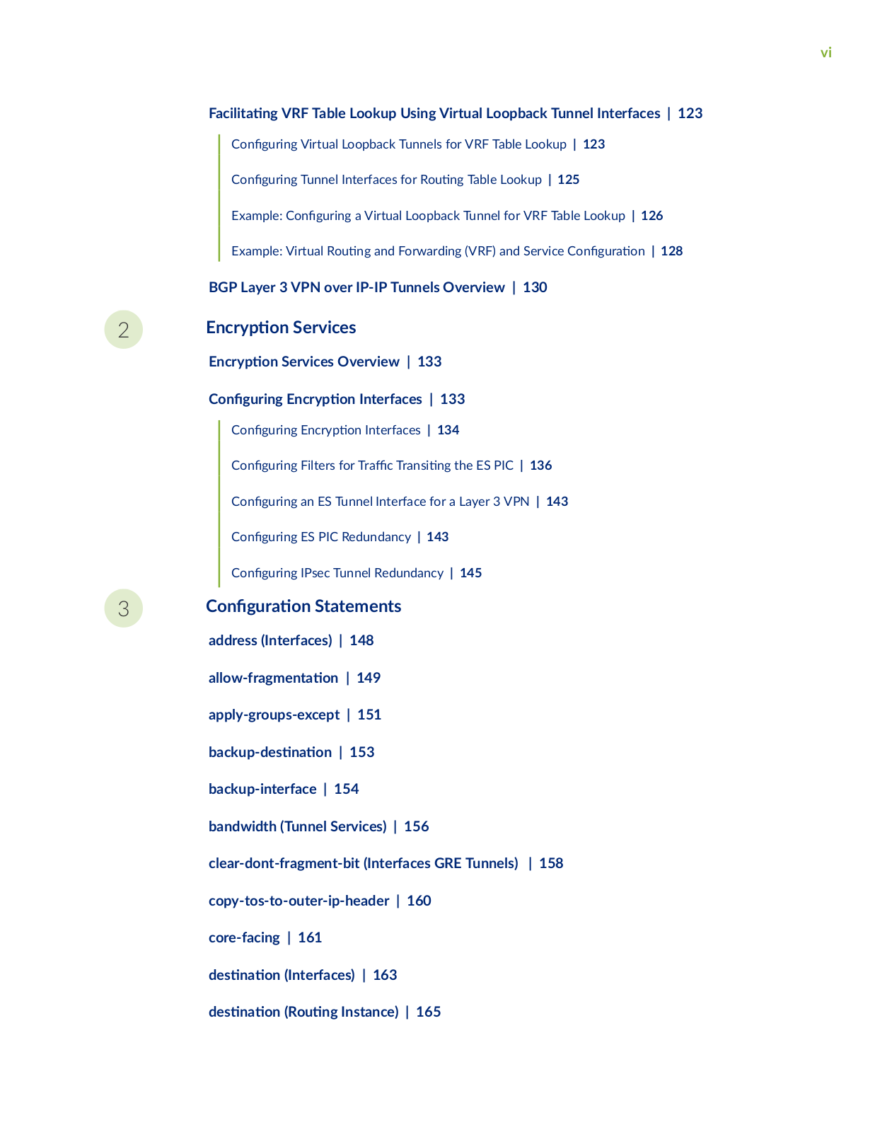
vi

F c


n VRF Table Lookup Using Virtual Loopback Tunnel Interfaces | 123


C

n

r n

Virtual Loopback Tunnels for VRF Table Lookup | 123


C

n

r n

Tunnel Interfaces for R n Table Lookup | 125


Example: C

n r n

a Virtual Loopback Tunnel for VRF Table Lookup | 126


Example: Virtual R

n and Forwarding (VRF) and Service C n r n | 128

BGP Layer 3 VPN over IP-IP Tunnels Overview | 130

ncry

n Services

ncry


n Services Overview | 133

C n


r n

ncry

n Interfaces | 133


C

n

r n

ncry n Interfaces | 134


C

n

r n

Filters for r c r ns n the ES PIC | 136


C

n

r n

an ES Tunnel Interface for a Layer 3 VPN | 143


C n

r n

ES PIC Redundancy | 143


C n

r n

IPsec Tunnel Redundancy | 145


C n


r

n Statements

address (Interfaces) | 148


w

r

m n

n | 149

apply-groups-except | 151

b c


s

n

n | 153

backup-interface | 154

bandwidth (Tunnel Services) | 156

clear-dont-fragment-bit (Interfaces GRE Tunnels) | 158 copy-tos-to-outer-ip-header | 160

core-facing | 161

s

n

n (Interfaces) | 163

s

n

n (R

n Instance) | 165

vii

s

n

n (Tunnel Remote End) | 166

s

n

n n

w r s | 168

s

n

n

r (FTI) | 170

do-not-fragment | 171 dynamic-tunnels | 173

sns | 176

nc s

n

| 177

fabric loopback wan | 179

family | 181


family bridge | 183


family bridge (GRE Interfaces) | 185

r | 187


m

(OAM) | 189

interfaces | 190

ipip | 192


ipsec-sa | 193


v

m

| 195

key | 197


m c s

n y | 199

peer-unit | 200

r c r

c

y | 202

reassemble-packets | 203

redundancy-group (Interfaces) | 205

redundancy-group (Chassis - MX Series) | 207 r n ns nc | 209

viii

r

n

ns nc s | 210

r

n

ns | 212

source | 214


source | 215


source-address | 217


| 219


tunnel | 221


tunnel | 223


nn

rm n


n ( ) | 225

tunnel-services (Chassis) | 226

udp (FTI) | 228


unit (Interfaces)

|

230

unit (Interfaces)

|

232

vni (Interfaces) |


234

vxlan-gpe (FTI) | 235

4

C n

r

n Statements: Generic R

n nc s

n (GRE) Tunnel

c

s

n using Flexible Tunnel Interfaces (FTIs)


address | 239


s

n n | 240


nc

s

n | 242


gre | 243


interface (R

n Instances) | 245


key | 247


source | 248 tunnel | 250

ix

nn rm n n | 252

5

r

n

Commands


clear ike s

c

r

y

ss

c


ns | 256


clear ipsec s

c

r

y

ss

c

ns | 257


request ipsec switch | 260


request security c

r

c


enroll (Signed) | 262


request security c

r

c


enroll (Unsigned) | 265


request security key-pair | 267


request system c r

c


add | 269


show ike s c

r

y

ss c


ns | 271


show interfaces (

ncry


n) | 277


show interfaces (GRE) | 287


show interfaces (IP-over-IP) | 302


show interfaces (Logical Tunnel) | 309


show interfaces (


c s Tunnel) | 319


show interfaces (PIM) | 327


show interfaces (Virtual Loopback Tunnel) | 334


show interfaces

| 342


show ipsec c r

c

s | 358


show ipsec redundancy | 362


show ipsec s c

r

y

ss

c

ns | 365


show system c r

c


| 371

x

About This Guide

Use this guide to c n

r and monitor tunneling, which encapsulates packets inside a transport

protocol, providing a private, secure path through an otherwise public network.

Juniper Tunnel and Encryption Services Interfaces User Manual

1

CHAPTER

Tunnel Services

Tunnel Services Overview | 2


C

n

r n

Tunnel Interfaces | 13


C

n

r n

Flexible Tunnel Interfaces

| 31

C

n

r n

GRE Tunnel Interfaces | 50

C

n

r n

IP Tunnel Interfaces | 62


Filtering Unicast Packets Through M

c s Tunnel Interfaces | 64

C

nn c

n

Logical Systems Using Logical Tunnel Interfaces | 74

C

n

r n

Layer 2 Ethernet Services over GRE Tunnel Interfaces | 101

C n

r n

PIM Tunnels | 122


F c

n

VRF Table Lookup Using Virtual Loopback Tunnel Interfaces | 123

BGP Layer 3 VPN over IP-IP Tunnels Overview | 130

2

Tunnel Services Overview

IN THIS SECTION

Tunnel Services Overview | 2

Tunnel Interfaces on MX Series Routers with Line Cards (MPC7E through MPC11E) | 6

Dynamic Tunnels Overview | 12

Tunnel Services Overview

By nc

s

n arbitrary packets inside a transport protocol, tunneling provides a private, secure path

through an otherwise public network. Tunnels connect

sc n

n

s subnetworks and enable


ncry

n interfaces, virtual private networks (VPNs), and MPLS. If you have a Tunnel Physical Interface

Card (PIC) installed in your M Series or T Series router, you can c n

r unicast, m c s

and logical

tunnels.


You can c n


r two types of tunnels for VPNs: one to facilitate r

n table lookups and another to

facilitate VPN r

n

and forwarding instance (VRF) table lookups.


For n

rm

n about

ncry

n interfaces, see C n

r n

ncry

n Interfaces. For n

rm

n

about VPNs, see the Junos OS VPNs Library for R

n Devices. For n rm

n about MPLS, see the

MPLS

c

ns User Guide.


On SRX Series devices, Generic R

n nc s

n (GRE) and IP-IP tunnels use internal interfaces,

gr-0/0/0 and ip-0/0/0, r s c v

y The Junos OS creates these interfaces at system bootup; they are

not associated with physical interfaces.


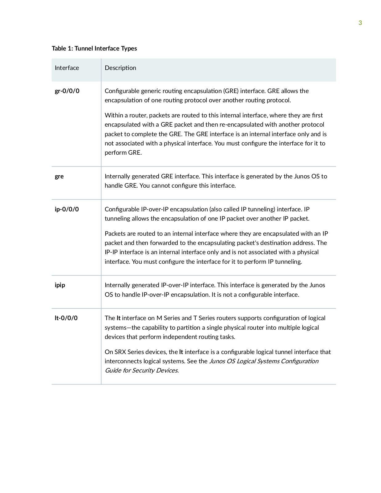
The Juniper Networks Junos OS supports the tunnel types shown in the following table.

3

Table 1: Tunnel Interface Types


Interface

scr

n


gr-0/0/0

C n

r b

generic r

n

nc

s


n (GRE) interface. GRE allows the


nc s


n of one r

n

protocol over another r

n

protocol.


Within a router, packets are routed to this internal interface, where they are

rs


encapsulated with a GRE packet and then re-encapsulated with another protocol


packet to complete the GRE. The GRE interface is an internal interface only and is


not associated with a physical interface. You must c n

r the interface for it to


perform GRE.


gre

Internally generated GRE interface. This interface is generated by the Junos OS to


handle GRE. You cannot c n

r

this interface.


ip-0/0/0

C n

r b

IP-over-IP

nc

s

n (also called IP tunneling) interface. IP


tunneling allows the nc

s

n of one IP packet over another IP packet.


Packets are routed to an internal interface where they are encapsulated with an IP


packet and then forwarded to the

nc

s

n

packet's

s

n

n address. The


IP-IP interface is an internal interface only and is not associated with a physical


interface. You must c n

r

the interface for it to perform IP tunneling.


ipip

Internally generated IP-over-IP interface. This interface is generated by the Junos


OS to handle IP-over-IP

nc

s

n It is not a c n

r b

interface.


lt-0/0/0

The lt interface on M Series and T Series routers supports c

n

r


n of logical


systems—the capability to

r

n a single physical router into m


logical


devices that perform independent r

n

tasks.


On SRX Series devices, the lt interface is a c n

r b

logical tunnel interface that


interconnects logical systems. See the Junos OS Logical Systems C

n

r

n


Guide for Security Devices.


4

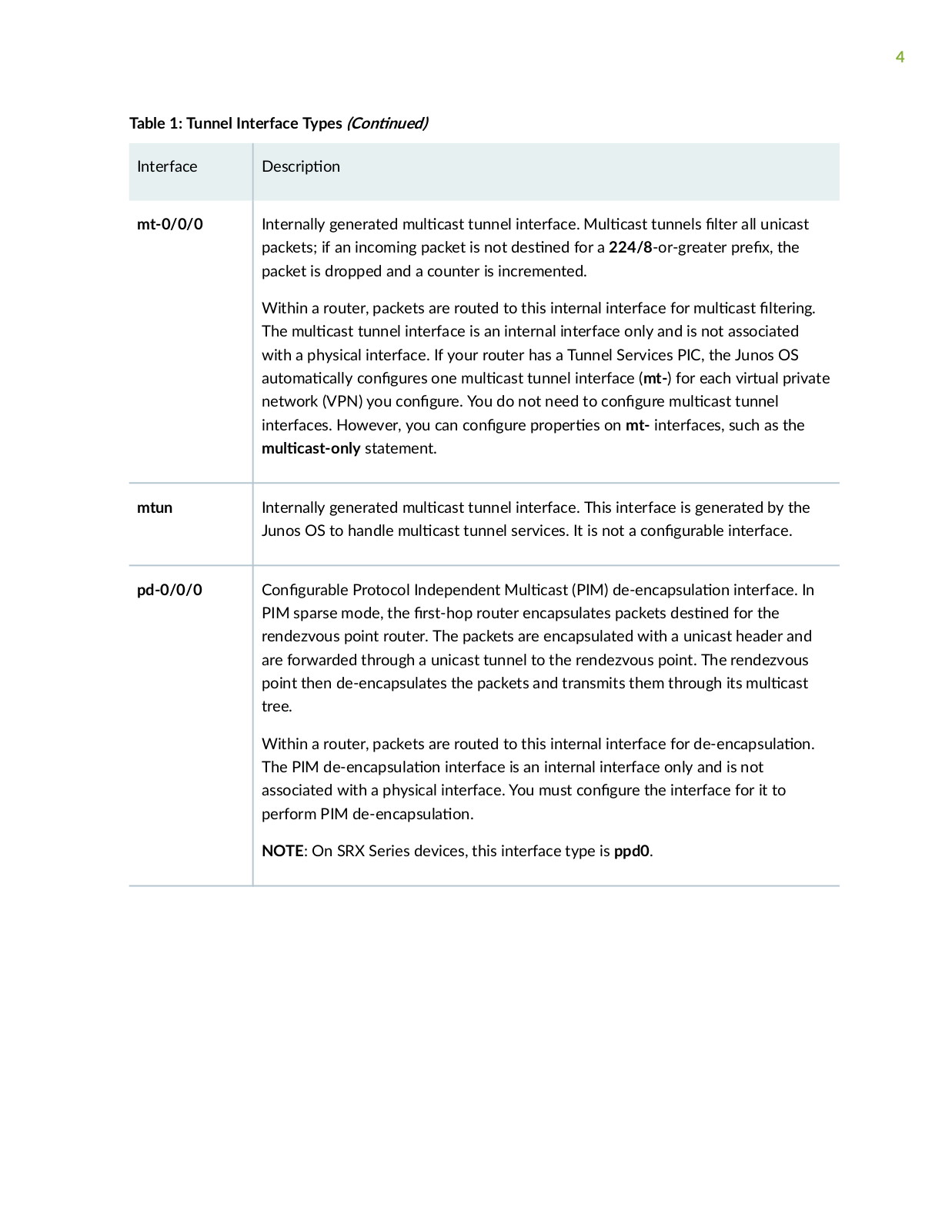
Table 1: Tunnel Interface Types (C n

n

)


Interface


scr

n


mt-0/0/0


Internally generated m

c s

tunnel interface. M c s

tunnels

r all unicast


packets; if an incoming packet is not

s n

for a 224/8-or-greater

r

x the


packet is dropped and a counter is incremented.


Within a router, packets are routed to this internal interface for m

c s

r n


The m

c s tunnel interface is an internal interface only and is not associated


with a physical interface. If your router has a Tunnel Services PIC, the Junos OS


m

c y c n

r

s one m

c s

tunnel interface (mt-) for each virtual private


network (VPN) you c n

r

You do not need to c n

r m c s

tunnel


interfaces. However, you can c n

r

r

r s on mt- interfaces, such as the

mc s n y statement.

mtun

Internally generated m

c s

tunnel interface. This interface is generated by the


Junos OS to handle m

c s

tunnel services. It is not a c n

r b

interface.


pd-0/0/0

C n

r b

Protocol Independent M c s (PIM)

nc

s

n interface. In


PIM sparse mode, the

rs

router encapsulates packets

s n

for the


rendezvous point router. The packets are encapsulated with a unicast header and


are forwarded through a unicast tunnel to the rendezvous point. The rendezvous


point then de-encapsulates the packets and transmits them through its m

c s


tree.


Within a router, packets are routed to this internal interface for

nc s

n


The PIM

nc s

n interface is an internal interface only and is not


associated with a physical interface. You must c n

r the interface for it to


perform PIM

nc s


n


NOTE: On SRX Series devices, this interface type is ppd0.

5

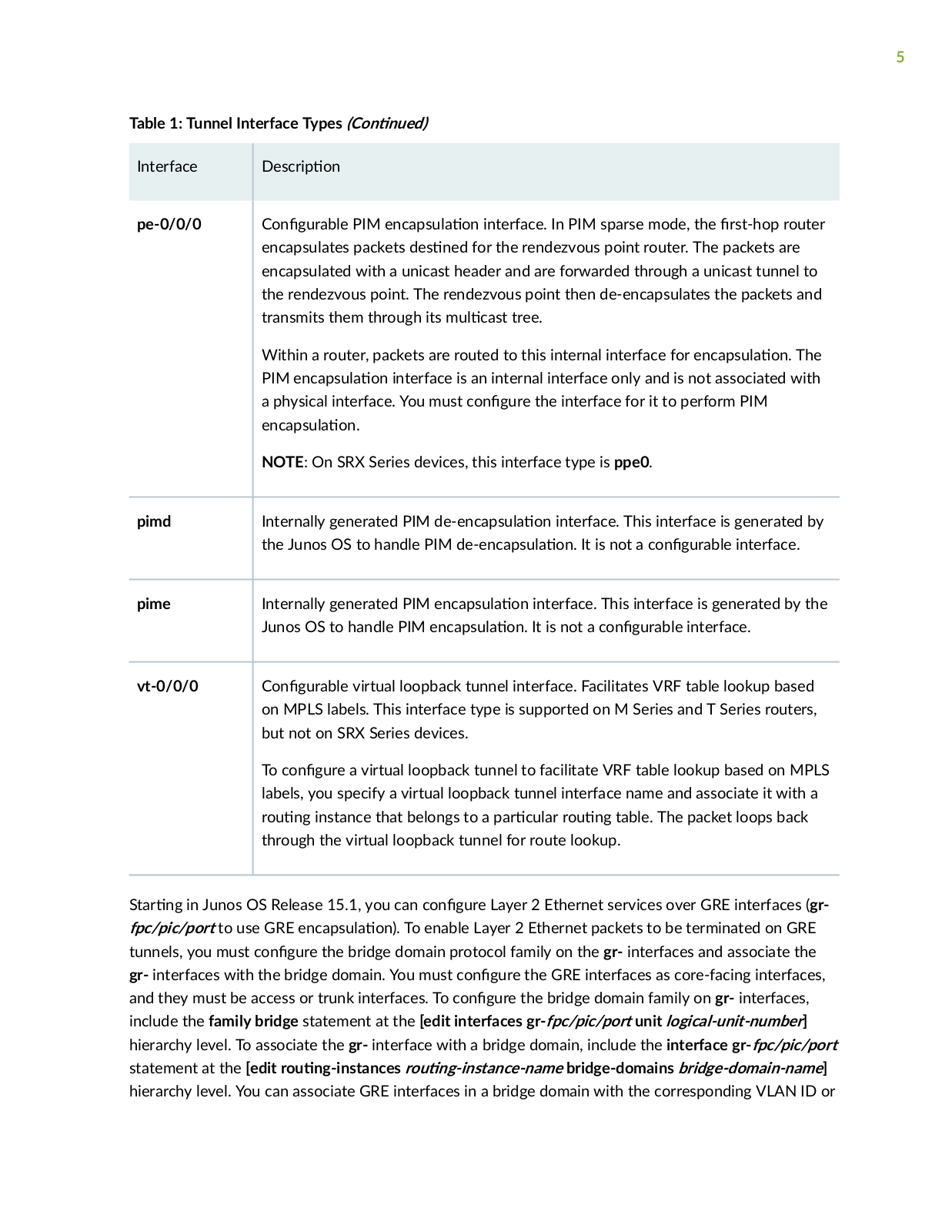
Table 1: Tunnel Interface Types (C n

n

)


Interface


scr

n


pe-0/0/0


C n

r b

PIM

nc

s

n interface. In PIM sparse mode, the

rs

router


encapsulates packets

s n

for the rendezvous point router. The packets are


encapsulated with a unicast header and are forwarded through a unicast tunnel to


the rendezvous point. The rendezvous point then de-encapsulates the packets and


transmits them through its m

c s

tree.


Within a router, packets are routed to this internal interface for nc

s

n The


PIM

nc s

n interface is an internal interface only and is not associated with


a physical interface. You must c n

r the interface for it to perform PIM


nc

s

n


NOTE: On SRX Series devices, this interface type is ppe0.

pimd

Internally generated PIM


nc

s


n interface. This interface is generated by


the Junos OS to handle PIM


nc

s

n It is not a c n

r b interface.


pime

Internally generated PIM

nc

s


n interface. This interface is generated by the


Junos OS to handle PIM

nc

s


n It is not a c n

r b

interface.


vt-0/0/0

C n


r b

virtual loopback tunnel interface. Facilitates VRF table lookup based


on MPLS labels. This interface type is supported on M Series and T Series routers,


but not on SRX Series devices.


To c

n

r

a virtual loopback tunnel to facilitate VRF table lookup based on MPLS


labels, you specify a virtual loopback tunnel interface name and associate it with a


r

n instance that belongs to a

r c

r r

n table. The packet loops back


through the virtual loopback tunnel for route lookup.


S r n in Junos OS Release 15.1, you can c

n

r

Layer 2 Ethernet services over GRE interfaces (gr-

fpc/pic/port to use GRE

nc s

n) To enable Layer 2 Ethernet packets to be terminated on GRE

tunnels, you must c

n

r the bridge domain protocol family on the gr- interfaces and associate the

gr- interfaces with the bridge domain. You must c

n


r the GRE interfaces as core-facing interfaces,

and they must be access or trunk interfaces. To c

n

r the bridge domain family on gr- interfaces,

include the family bridge statement at the [edit interfaces gr-fpc/pic/port unit logical-unit-number] hierarchy level. To associate the gr- interface with a bridge domain, include the interface gr-fpc/pic/port statement at the [edit r n ns nc s r n ns nc n m bridge-domains bridge-domain-name] hierarchy level. You can associate GRE interfaces in a bridge domain with the corresponding VLAN ID or

6

list of VLAN IDs in a bridge domain by including the vlan-id (all | none | number) statement or the vlan- id-list [ vlan-id-numbers ] statement at the [edit bridge-domains bridge-domain-name] hierarchy level. The VLAN IDs c n r for the bridge domain must match with the VLAN IDs that you c n r for GRE interfaces by using the vlan-id (all | none | number) statement or the vlan-id-list [ vlan-id-numbers ] statement at the [edit interfaces gr-fpc/pic/port unit logical-unit-number] hierarchy level. You can also

c

n

r GRE interfaces within a bridge domain associated with a virtual switch instance. Layer 2

Ethernet packets over GRE tunnels are also supported with the GRE key


n The gre-key match

c

n

n allows a user to match against the GRE key

which is an

n

in GRE

encapsulated packets. The key can be matched as a single key value, a range of key values, or both.

NOTE: S r n in Junos OS Release 16.1, Layer 2 Port mirroring to a remote collector over a GRE interface is supported.

SEE ALSO

GRE Keepalive Time Overview

C

n

r n

Unicast Tunnels


R s r c

n

Tunnels to M c s r c


C

n

r n Tunnel Interfaces on T4000 Routers

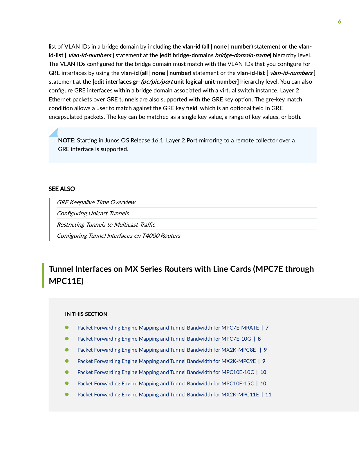
Tunnel Interfaces on MX Series Routers with Line Cards (MPC7E through MPC11E)

IN THIS SECTION

Packet Forwarding Engine Mapping and Tunnel Bandwidth for MPC7E-MRATE | 7

Packet Forwarding Engine Mapping and Tunnel Bandwidth for MPC7E-10G | 8

Packet Forwarding Engine Mapping and Tunnel Bandwidth for MX2K-MPC8E | 9

Packet Forwarding Engine Mapping and Tunnel Bandwidth for MX2K-MPC9E | 9

Packet Forwarding Engine Mapping and Tunnel Bandwidth for MPC10E-10C | 10

Packet Forwarding Engine Mapping and Tunnel Bandwidth for MPC10E-15C | 10

Packet Forwarding Engine Mapping and Tunnel Bandwidth for MX2K-MPC11E | 11

7

MPC7E-10G, MPC7E-MRATE, MX2K-MPC8E, and MX2K-MPC9E support a total of four inline tunnel interfaces per MPC, one per PIC. You can create a set of tunnel interfaces per PIC slot up to a maximum of four slots (from 0 through 3) on MX Series routers with these MPCs.

MPC10E-15C supports three inline tunnel interfaces per MPC, one per PIC, whereas MPC10E-10C supports two inline tunnel interfaces per MPC, one per PIC. On MX Series routers with MPC10E-15C, you can

create a set of tunnel interfaces per PIC slot up to a maximum of three slots (from 0 through 2). And, on MX Series routers with MPC10E-10C, you can create a set of tunnel interfaces per PIC slot up to a maximum of two slots (0 and 1).

MX2K-MPC11E supports 8 inline tunnel interfaces per MPC, one per PIC. On MX Series routers with MX2K-MPC11E, you can create a set of tunnel interfaces per PIC slot up to a maximum of eight slots (from 0 through 7). These PICs are referred to as pseudo tunnel PICs. You create tunnel interfaces on MX Series routers with MPC7E-10G, MPC7E-MRATE, MX2K-MPC8E, MX2K-MPC9E, MPC10E-15C, MPC10E-10C, and MX2K-MPC11E by including the following statements at the [edit chassis] hierarchy level:

[edit chassis]

fpc slot-number {

pic number {

tunnel-services {

bandwidth ;

}

}

}

Packet Forwarding Engine Mapping and Tunnel Bandwidth for MPC7E-MRATE

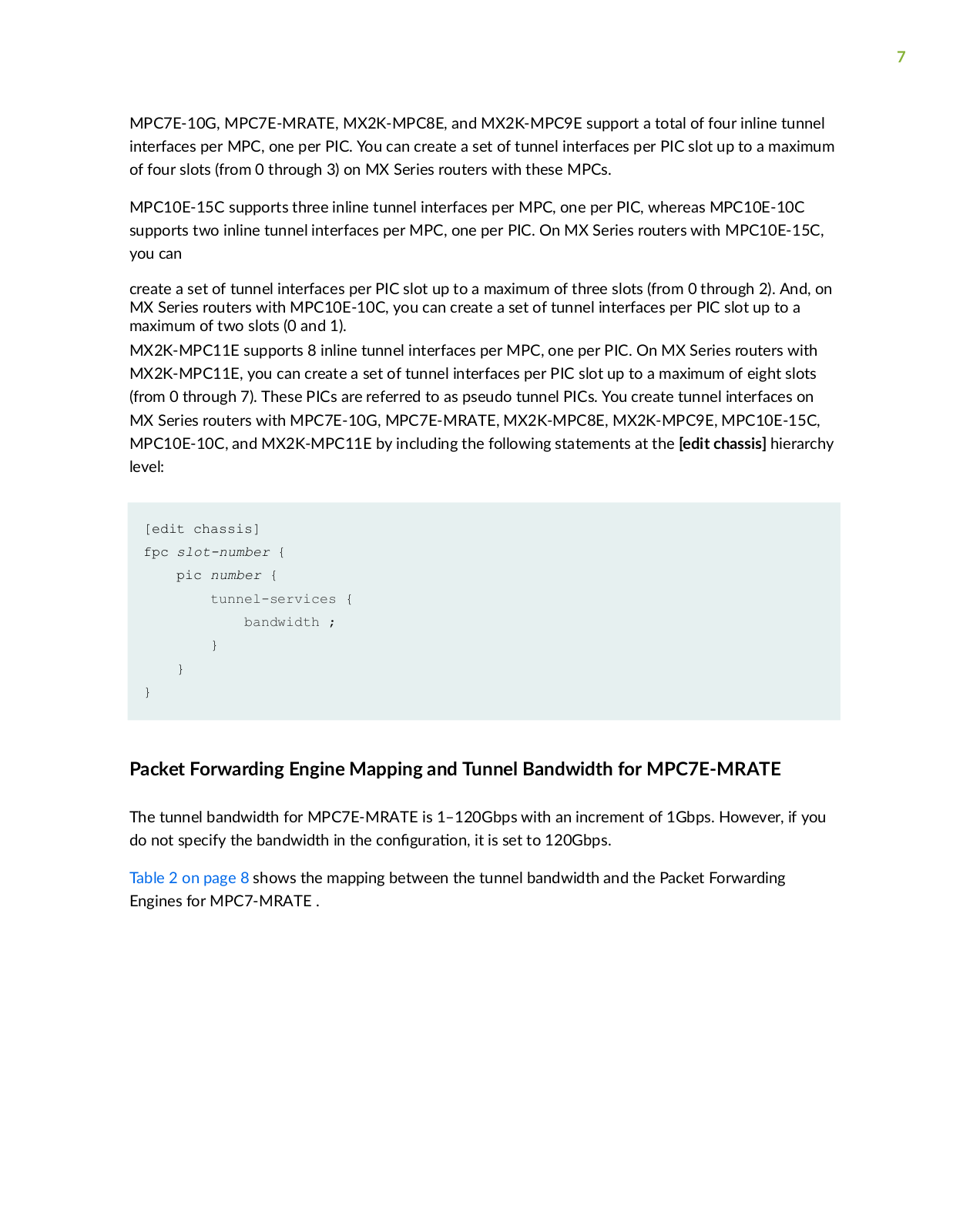
The tunnel bandwidth for MPC7E-MRATE is 1–120Gbps with an increment of 1Gbps. However, if you do not specify the bandwidth in the c n r n it is set to 120Gbps.

Table 2 on page 8 shows the mapping between the tunnel bandwidth and the Packet Forwarding Engines for MPC7-MRATE .

8

Table 2: Packet Forwarding Engine Mapping and Tunnel Bandwidth for MPC7E-MRATE

Pseudo Tunnel

Maximum

PFE Mapping

Maximum Tunnel

Maximum PFE

PIC

Bandwidth per


Bandwidth per PFE

Bandwidth


Tunnel PIC


PIC0

120Gbps

PFE0

120Gbps

240Gbps


PIC1

120Gbps


PIC2

120Gbps

PFE1

120Gbps

240Gbps


PIC3

120Gbps


Packet Forwarding Engine Mapping and Tunnel Bandwidth for MPC7E-10G

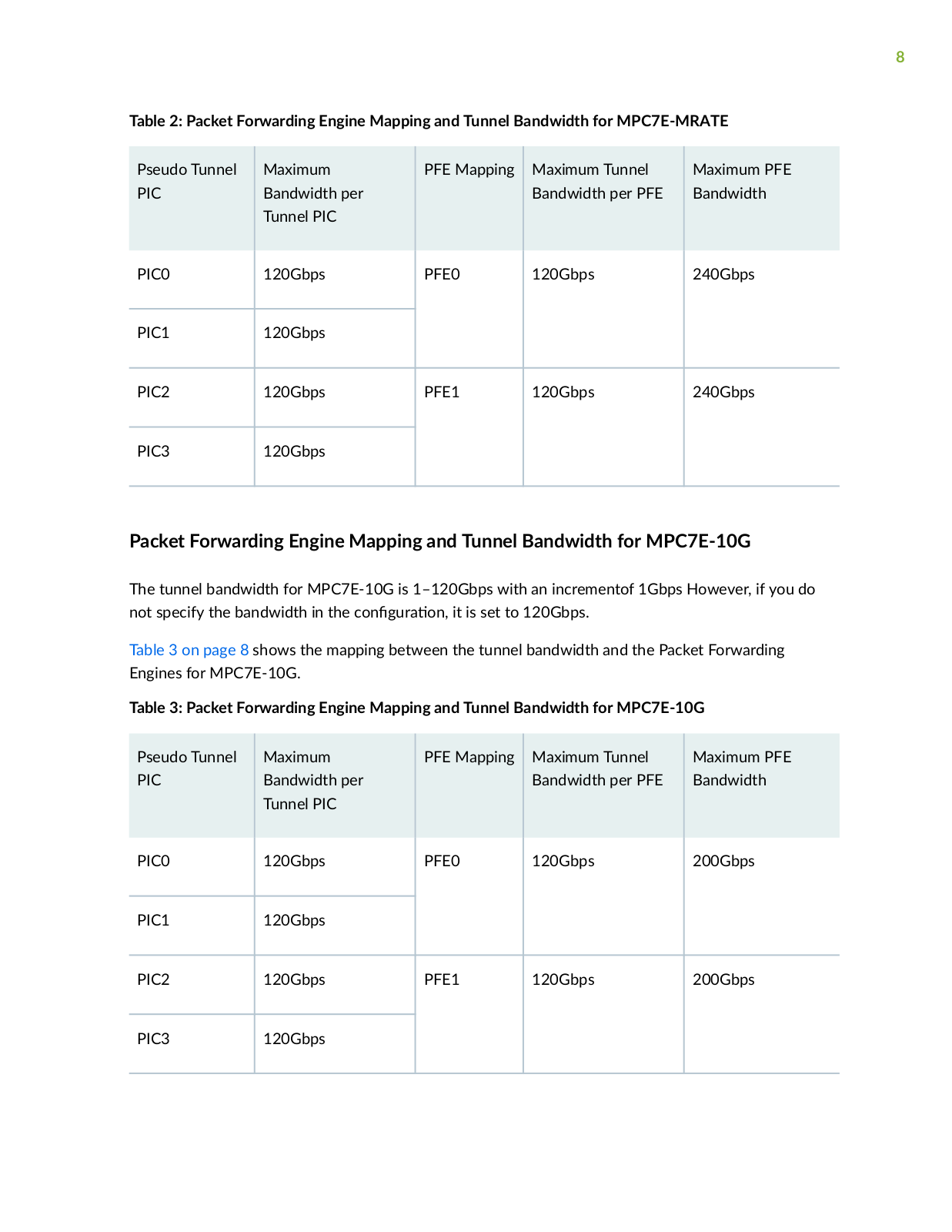
The tunnel bandwidth for MPC7E-10G is 1–120Gbps with an incrementof 1Gbps However, if you do not specify the bandwidth in the c n r n it is set to 120Gbps.

Table 3 on page 8 shows the mapping between the tunnel bandwidth and the Packet Forwarding Engines for MPC7E-10G.

Table 3: Packet Forwarding Engine Mapping and Tunnel Bandwidth for MPC7E-10G

Pseudo Tunnel

Maximum

PFE Mapping

Maximum Tunnel

Maximum PFE

PIC

Bandwidth per


Bandwidth per PFE

Bandwidth


Tunnel PIC


PIC0

120Gbps

PFE0

120Gbps

200Gbps


PIC1

120Gbps


PIC2

120Gbps

PFE1

120Gbps

200Gbps


PIC3

120Gbps


9

Packet Forwarding Engine Mapping and Tunnel Bandwidth for MX2K-MPC8E

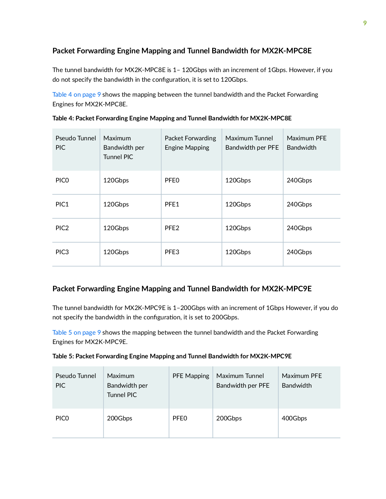
The tunnel bandwidth for MX2K-MPC8E is 1– 120Gbps with an increment of 1Gbps. However, if you do not specify the bandwidth in the c n r n it is set to 120Gbps.

Table 4 on page 9 shows the mapping between the tunnel bandwidth and the Packet Forwarding Engines for MX2K-MPC8E.

Table 4: Packet Forwarding Engine Mapping and Tunnel Bandwidth for MX2K-MPC8E

Pseudo Tunnel

Maximum

Packet Forwarding

Maximum Tunnel

Maximum PFE

PIC

Bandwidth per

Engine Mapping

Bandwidth per PFE

Bandwidth


Tunnel PIC


PIC0

120Gbps

PFE0

120Gbps

240Gbps


PIC1

120Gbps

PFE1

120Gbps

240Gbps


PIC2

120Gbps

PFE2

120Gbps

240Gbps


PIC3

120Gbps

PFE3

120Gbps

240Gbps


Packet Forwarding Engine Mapping and Tunnel Bandwidth for MX2K-MPC9E

The tunnel bandwidth for MX2K-MPC9E is 1–200Gbps with an increment of 1Gbps However, if you do not specify the bandwidth in the c n r n it is set to 200Gbps.

Table 5 on page 9 shows the mapping between the tunnel bandwidth and the Packet Forwarding Engines for MX2K-MPC9E.

Table 5: Packet Forwarding Engine Mapping and Tunnel Bandwidth for MX2K-MPC9E

Pseudo Tunnel

Maximum

PFE Mapping

Maximum Tunnel

Maximum PFE

PIC

Bandwidth per


Bandwidth per PFE

Bandwidth


Tunnel PIC


PIC0

200Gbps

PFE0

200Gbps

400Gbps


10

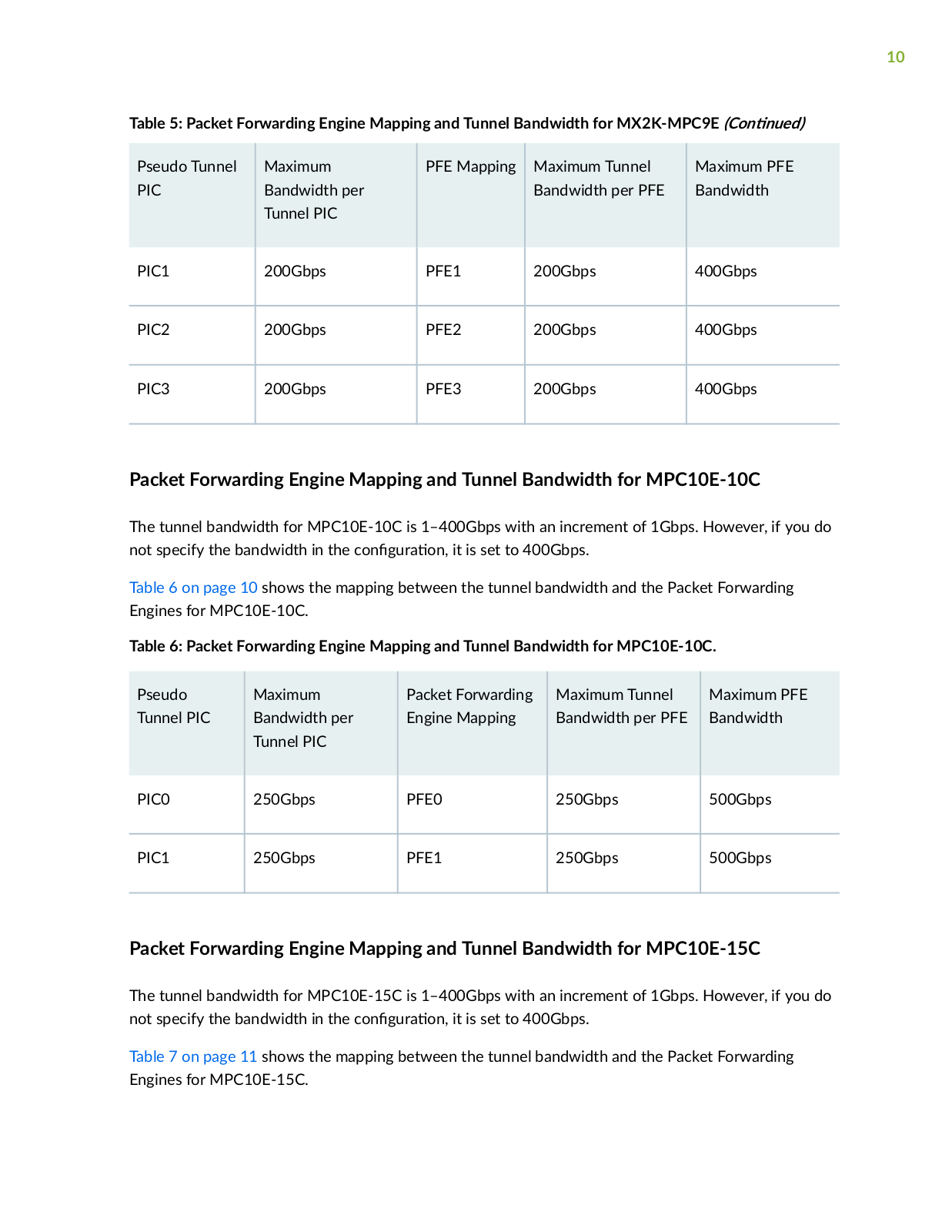
Table 5: Packet Forwarding Engine Mapping and Tunnel Bandwidth for MX2K-MPC9E (C n n )

Pseudo Tunnel

Maximum

PFE Mapping

Maximum Tunnel

Maximum PFE

PIC

Bandwidth per


Bandwidth per PFE

Bandwidth


Tunnel PIC


PIC1

200Gbps

PFE1

200Gbps

400Gbps


PIC2

200Gbps

PFE2

200Gbps

400Gbps


PIC3

200Gbps

PFE3

200Gbps

400Gbps


Packet Forwarding Engine Mapping and Tunnel Bandwidth for MPC10E-10C

The tunnel bandwidth for MPC10E-10C is 1–400Gbps with an increment of 1Gbps. However, if you do not specify the bandwidth in the c n r n it is set to 400Gbps.

Table 6 on page 10 shows the mapping between the tunnel bandwidth and the Packet Forwarding Engines for MPC10E-10C.

Table 6: Packet Forwarding Engine Mapping and Tunnel Bandwidth for MPC10E-10C.

Pseudo

Maximum

Packet Forwarding

Maximum Tunnel

Maximum PFE

Tunnel PIC

Bandwidth per

Engine Mapping

Bandwidth per PFE

Bandwidth


Tunnel PIC


PIC0

250Gbps

PFE0

250Gbps

500Gbps


PIC1

250Gbps

PFE1

250Gbps

500Gbps


Packet Forwarding Engine Mapping and Tunnel Bandwidth for MPC10E-15C

The tunnel bandwidth for MPC10E-15C is 1–400Gbps with an increment of 1Gbps. However, if you do not specify the bandwidth in the c n r n it is set to 400Gbps.

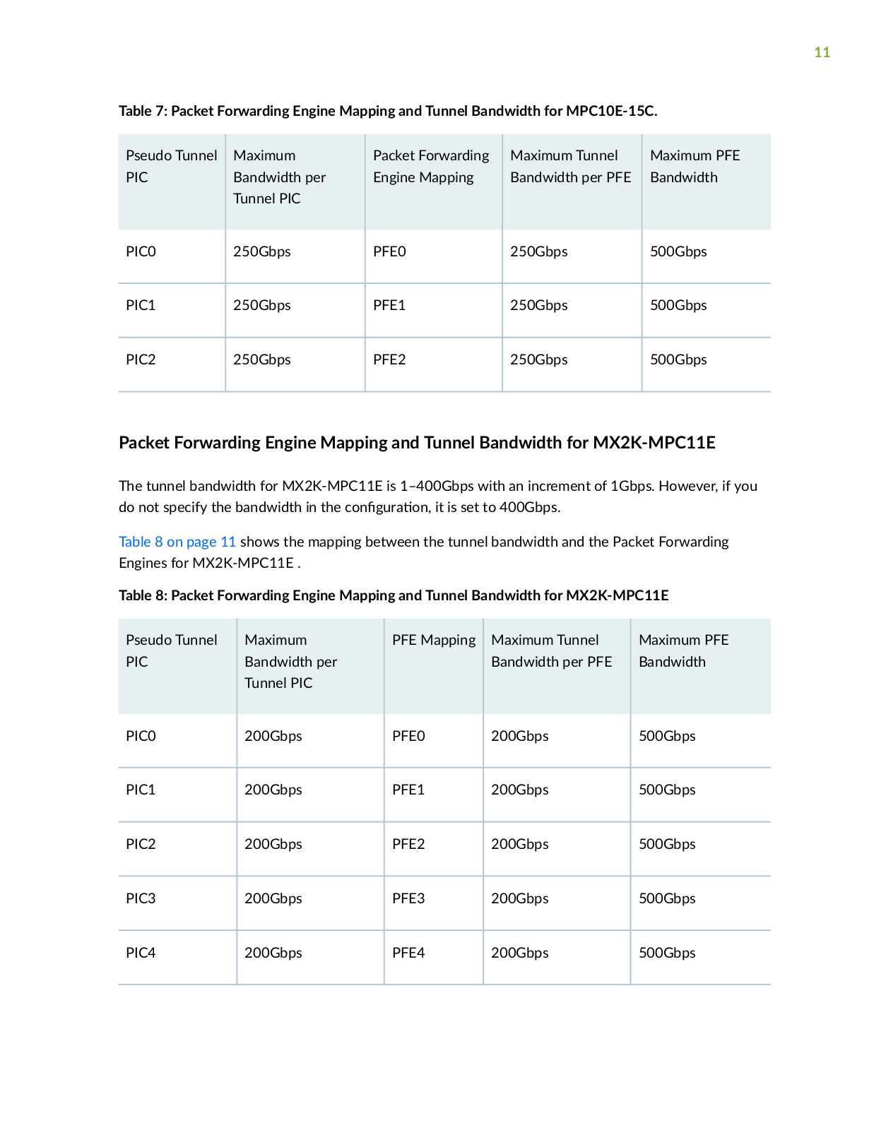
Table 7 on page 11 shows the mapping between the tunnel bandwidth and the Packet Forwarding Engines for MPC10E-15C.

11

Table 7: Packet Forwarding Engine Mapping and Tunnel Bandwidth for MPC10E-15C.

Pseudo Tunnel

Maximum

Packet Forwarding

Maximum Tunnel

Maximum PFE

PIC

Bandwidth per

Engine Mapping

Bandwidth per PFE

Bandwidth


Tunnel PIC


PIC0

250Gbps

PFE0

250Gbps

500Gbps


PIC1

250Gbps

PFE1

250Gbps

500Gbps


PIC2

250Gbps

PFE2

250Gbps

500Gbps


Packet Forwarding Engine Mapping and Tunnel Bandwidth for MX2K-MPC11E

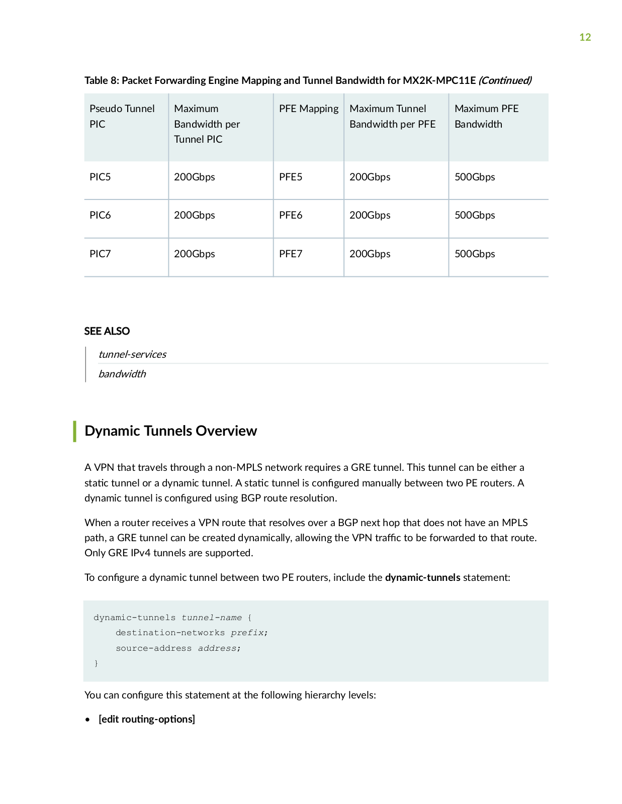
The tunnel bandwidth for MX2K-MPC11E is 1–400Gbps with an increment of 1Gbps. However, if you do not specify the bandwidth in the c n r n it is set to 400Gbps.

Table 8 on page 11 shows the mapping between the tunnel bandwidth and the Packet Forwarding Engines for MX2K-MPC11E .

Table 8: Packet Forwarding Engine Mapping and Tunnel Bandwidth for MX2K-MPC11E

Pseudo Tunnel

Maximum

PFE Mapping

Maximum Tunnel

Maximum PFE

PIC

Bandwidth per


Bandwidth per PFE

Bandwidth


Tunnel PIC


PIC0

200Gbps

PFE0

200Gbps

500Gbps


PIC1

200Gbps

PFE1

200Gbps

500Gbps


PIC2

200Gbps

PFE2

200Gbps

500Gbps


PIC3

200Gbps

PFE3

200Gbps

500Gbps


PIC4

200Gbps

PFE4

200Gbps

500Gbps


12

Table 8: Packet Forwarding Engine Mapping and Tunnel Bandwidth for MX2K-MPC11E (C n n )

Pseudo Tunnel

Maximum

PFE Mapping

Maximum Tunnel

Maximum PFE

PIC

Bandwidth per


Bandwidth per PFE

Bandwidth


Tunnel PIC


PIC5

200Gbps

PFE5

200Gbps

500Gbps


PIC6

200Gbps

PFE6

200Gbps

500Gbps


PIC7

200Gbps

PFE7

200Gbps

500Gbps


SEE ALSO

tunnel-services

bandwidth

Dynamic Tunnels Overview

A VPN that travels through a non-MPLS network requires a GRE tunnel. This tunnel can be either a

s c tunnel or a dynamic tunnel. A s c tunnel is c n

r manually between two PE routers. A

dynamic tunnel is c n r using BGP route r s

n

When a router receives a VPN route that resolves over a BGP next hop that does not have an MPLS path, a GRE tunnel can be created dynamically, allowing the VPN r c to be forwarded to that route. Only GRE IPv4 tunnels are supported.

To c n r a dynamic tunnel between two PE routers, include the dynamic-tunnels statement:

dynamic-tunnels tunnel-name {

destination-networks prefix;

source-address address;

}


You can c

n

r this statement at the following hierarchy levels:

[edit r

n

ns

13

[edit r

n ns nc s r

n ns nc n m

r

n

ns


[edit logical-systems logical-system-name r

n


ns


[edit logical-systems logical-system-name r

n

ns

nc s r

n ns nc n m r

n

ns

SEE ALSO


dynamic-tunnels


Junos OS R

n Protocols Library


Junos OS VPNs Library for R

n

Devices

Release History Table


Release

scr

n


16.1


S r n

in Junos OS Release 16.1, Layer 2 Port mirroring to a remote collector over a GRE interface is


supported.


15.1


S r n

in Junos OS Release 15.1, you can c n r Layer 2 Ethernet services over GRE interfaces (gr-


fpc/pic/port to use GRE nc

s

n)


C n r n Tunnel Interfaces

IN THIS SECTION


Tunnel Interface C n

r n on MX Series Routers Overview | 14


C n

r n

Tunnel Interfaces on an MX Series Router with a 16x10GE 3D MPC | 16


C n

r n

Tunnel Interfaces on MX Series Routers with the MPC3E | 17


Example: C n r n

Tunnel Interfaces on the MPC3E | 18


C n

r n

Tunnel Interfaces on MX Series Routers with MPC4E | 20


C n

r n

Tunnel Interfaces on MX Series Routers with MPC7E-MRATE/MPC7E-10G | 21


C n

r n

Tunnel Interfaces on MX Series Routers with MX2K-MPC8E | 22


C n

r n

Tunnel Interfaces on MX Series Routers with MX2K-MPC9E | 24


C n

r n

Tunnel Interfaces on MX Series Routers with MPC10E-10C and MPC10E-15C | 25


14


C n

r n

Tunnel Interfaces on MX Series Routers with MX2K-MPC11E | 26


Example: C

n

r n

Tunnel Interfaces on a Gigabit Ethernet 40-Port DPC | 27


Example: C

n

r n

Tunnel Interfaces on a 10-Gigabit Ethernet 4-Port DPC | 28


C

n

r n

Tunnel Interfaces on MX 204 Routers | 28


C

n

r n

Tunnel Interfaces on T4000 Routers | 30


Tunnel Interface C n r

n on MX Series Routers Overview

Because MX Series routers do not support Tunnel Services PICs, you create tunnel interfaces on MX Series routers by including the following statements at the [edit chassis] hierarchy level:

[edit chassis] fpc slot-number {

pic number { tunnel-services {

bandwidth (1g | 10g | 20g | 30g | 40g | 50g | 60g | 70g | 80g | 90g

| 100g);

}

}

}

Where:

fpc slot-number is the slot number of the DPC, MPC, or MIC. On the MX80 router, possible values are 0 and 1. On other MX Series routers, if two SCBs are installed, the range is 0 through 11. If three SCBs are installed, the range is 0 through 5 and 7 through 11.

pic number is the slot number of the PIC. On MX80 routers, if the FPC is 0, the PIC number can only be 0. If the FPC is 1, the PIC range is 0 through 3. For all other MX Series routers, the range is 0 through 3.

bandwidth (1g | 10g | 20g | 30g | 40g | 50g | 60g | 70g | 80g | 90g | 100g) is the maximum amount of

bandwidth, in gigabits, that is available for tunnel r

c on each Packet Forwarding Engine. For MPCs

and MICs, this bandwidth is not reserved for tunnel r

c and can be shared by the network interfaces.

For DPCs, this bandwidth is reserved and cannot be shared by the network interfaces.

15

NOTE: When you use MPCs and MICs, tunnel interfaces are s ft interfaces and allow as much

rc as the forwarding-path allows, so it is advantageous to set up tunnel services without

r c

y m

n

r c by use of the bandwidth

n However, you must specify bandwidth

when c

n

r n

tunnel services for MX Series routers with DPCs or FPCs. The GRE key

n

is not supported on the tunnel interfaces for DPCs on MX960 routers.


If you specify a bandwidth that is not c m b tunnel services are not c v

For example, you

cannot specify a bandwidth of 1 Gbps for a Packet Forwarding Engine on a 10-Gigabit Ethernet 4-port DPC.

When you c n r tunnel interfaces on the Packet Forwarding Engine of a 10-Gigabit Ethernet 4-port DPC, the Ethernet interfaces for that port are removed from service and are no longer visible in the

command-line interface (CLI). The Packet Forwarding Engine of a 10-Gigabit Ethernet 4-port DPC


supports either tunnel interfaces or Ethernet interfaces, but not both. Each port on the 10-Gigabit


Ethernet 4-port DPC includes two LEDs, one for tunnel services and one for Ethernet services, to


indicate which type of service is being used. On the Gigabit Ethernet 40-port DPC, you can c

n

r

both tunnel and Ethernet interfaces at the same m


To verify that the tunnel interfaces have been created, issue the show interfaces terse

r

n

mode

command. For more n rm n see the CLI Explorer. The bandwidth that you specify determines the port number of the tunnel interfaces that are created. When you specify a bandwidth of 1g, the port number is always 10. When you specify any other bandwidth, the port number is always 0.

NOTE: When the tunnel bandwidth is ns c

in the R n Engine CLI, the maximum

tunnel bandwidth for an MPC3E is 60G.


NOTE: You cannot c n r ingress queueing and tunnel services on the same MPC because doing so causes PFE forwarding to stop. You can c n r and use each feature separately.

SEE ALSO

bandwidth (Tunnel Services)

tunnel-services (Chassis)

16

C n r n Tunnel Interfaces on an MX Series Router with a 16x10GE 3D MPC

MX960, MX480, and M240 routers support the 16-port 10-Gigabit Ethernet MPC (16x10GE 3D MPC) x c n r n Field Replaceable Unit (FRU). Each Packet Forwarding Engine on a 16x10GE MPC

can support a full-duplex 10Gbps tunnel without losing line-rate capacity. For example, a full-duplex 10Gbps tunnel can be hosted on a 10-Gigabit-Ethernet port, while two other 10-Gigabit-Ethernet ports on the same PFE can concurrently forward line-rate r c

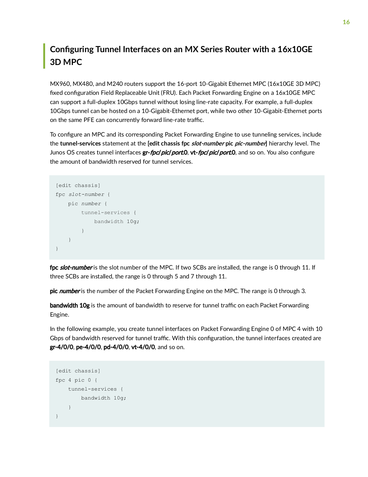
To c n r an MPC and its corresponding Packet Forwarding Engine to use tunneling services, include the tunnel-services statement at the [edit chassis fpc slot-number pic pic-number] hierarchy level. The Junos OS creates tunnel interfaces gr-fpc/pic/port.0, vt-fpc/pic/port.0, and so on. You also c n r the amount of bandwidth reserved for tunnel services.

[edit chassis]

fpc slot-number {

pic number {

tunnel-services {

bandwidth 10g;

}

}

}

fpc slot-number is the slot number of the MPC. If two SCBs are installed, the range is 0 through 11. If three SCBs are installed, the range is 0 through 5 and 7 through 11.

pic number is the number of the Packet Forwarding Engine on the MPC. The range is 0 through 3.

bandwidth 10g is the amount of bandwidth to reserve for tunnel r c on each Packet Forwarding Engine.

In the following example, you create tunnel interfaces on Packet Forwarding Engine 0 of MPC 4 with 10 Gbps of bandwidth reserved for tunnel r c With this c n r n the tunnel interfaces created are gr-4/0/0, pe-4/0/0, pd-4/0/0, vt-4/0/0, and so on.

[edit chassis]

fpc 4 pic 0 {

tunnel-services {

bandwidth 10g;

}

}

17

SEE ALSO

C n r n Junos OS to Run a S c c Network Services Mode in MX Series Routers

C n r n Tunnel Interfaces on MX Series Routers with the MPC3E

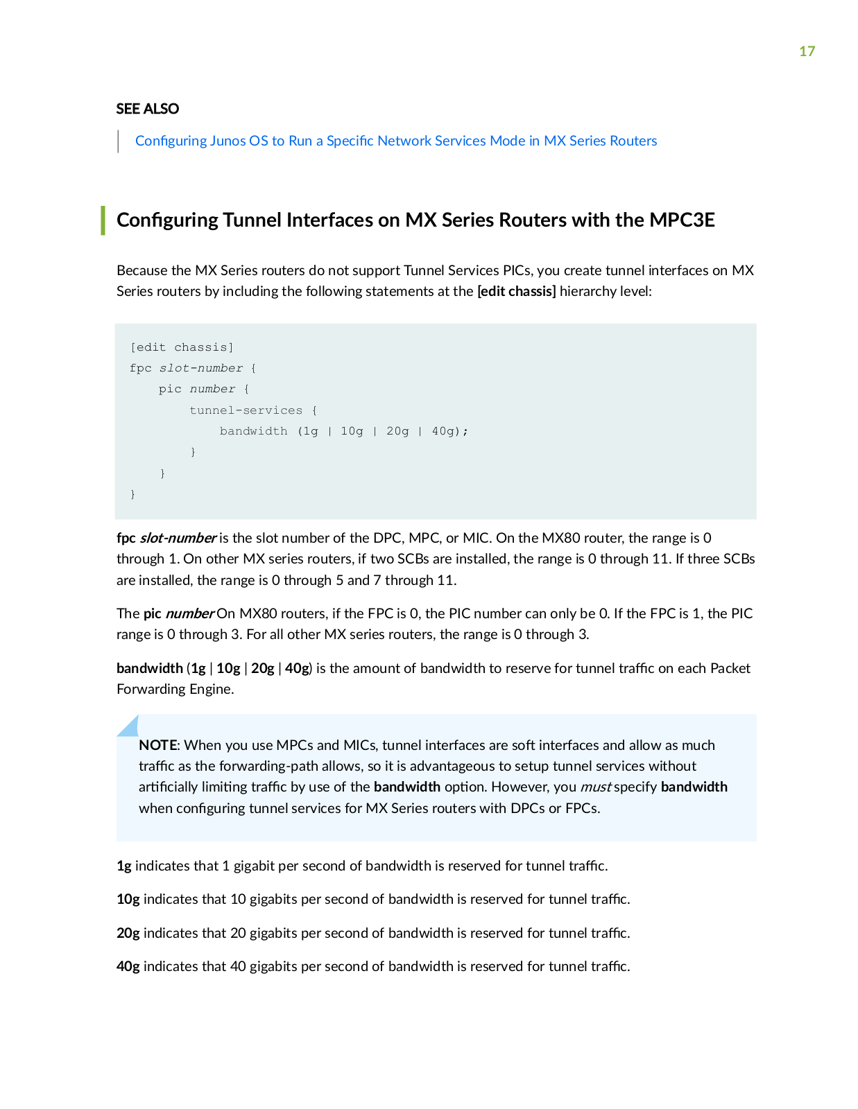
Because the MX Series routers do not support Tunnel Services PICs, you create tunnel interfaces on MX Series routers by including the following statements at the [edit chassis] hierarchy level:

[edit chassis]

fpc slot-number {

pic number {

tunnel-services {

bandwidth (1g | 10g | 20g | 40g);

}

}

}

fpc slot-number is the slot number of the DPC, MPC, or MIC. On the MX80 router, the range is 0 through 1. On other MX series routers, if two SCBs are installed, the range is 0 through 11. If three SCBs are installed, the range is 0 through 5 and 7 through 11.

The pic number On MX80 routers, if the FPC is 0, the PIC number can only be 0. If the FPC is 1, the PIC range is 0 through 3. For all other MX series routers, the range is 0 through 3.

bandwidth (1g | 10g | 20g | 40g) is the amount of bandwidth to reserve for tunnel r c on each Packet Forwarding Engine.

NOTE: When you use MPCs and MICs, tunnel interfaces are s ft interfaces and allow as much

rc as the forwarding-path allows, so it is advantageous to setup tunnel services without

r c

y m

n r c by use of the bandwidth

n However, you must specify bandwidth

when c

n

r n tunnel services for MX Series routers with DPCs or FPCs.


1g indicates that 1 gigabit per second of bandwidth is reserved for tunnel r

c


10g indicates that 10 gigabits per second of bandwidth is reserved for tunnel

r

c

20g indicates that 20 gigabits per second of bandwidth is reserved for tunnel

r

c

40g indicates that 40 gigabits per second of bandwidth is reserved for tunnel

r

c

18

If you specify a bandwidth that is not c m b tunnel services are not c v For example, you cannot specify a bandwidth of 1 Gbps for a Packet Forwarding Engine on a 10-Gigabit Ethernet 4-port DPC.

To verify that the tunnel interfaces have been created, issue the show interfaces terse r n mode command. For more n rm n see the CLI Explorer. The bandwidth that you specify determines the port number of the tunnel interfaces that are created. When you specify a bandwidth of 1g, the port number is always 10. When you specify any other bandwidth, the port number is always 0.

SEE ALSO

bandwidth (Tunnel Services)

tunnel-services (Chassis)

Example: C n r n Tunnel Interfaces on the MPC3E

IN THIS SECTION


Requirements for C n

r

n of Tunnel Interfaces on the MPC3E | 18


Ethernet Tunnel C n

r

n Overview | 18


C

n

r n

a 20-Gigabit Ethernet Tunnel | 19


C

n

r n

a Tunnel With

ns c

Bandwidth | 20


Requirements for C n r n of Tunnel Interfaces on the MPC3E

This example requires MX Series routers with the MPC3E.

Ethernet Tunnel C n r

n Overview

MX Series routers do not support Tunnel Services PICs. However, you can create one set of tunnel interfaces per pic slot up to a maximum of 4 slots from 0-3 on MX Series routers with the MPC3E.

To c n

r the tunnels, include the tunnel-services statement and an

n bandwidth of (1g | 10g |

20g | 30g | 40g) at the [edit chassis] hierarchy level.


19

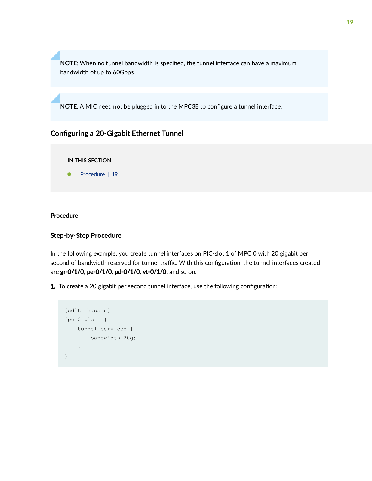
NOTE: When no tunnel bandwidth is s c

the tunnel interface can have a maximum

bandwidth of up to 60Gbps.


NOTE: A MIC need not be plugged in to the MPC3E to c n r a tunnel interface.

C n r n a 20-Gigabit Ethernet Tunnel

IN THIS SECTION

Procedure | 19

Procedure

Step-by-Step Procedure

In the following example, you create tunnel interfaces on PIC-slot 1 of MPC 0 with 20 gigabit per second of bandwidth reserved for tunnel r c With this c n r n the tunnel interfaces created are gr-0/1/0, pe-0/1/0, pd-0/1/0, vt-0/1/0, and so on.

1. To create a 20 gigabit per second tunnel interface, use the following c n

r

n

[edit chassis]

fpc 0 pic 1 {

tunnel-services {

bandwidth 20g;

}

}

20

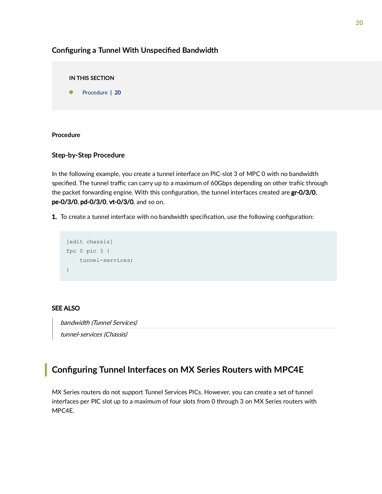
C n r n a Tunnel With ns c

Bandwidth

IN THIS SECTION

Procedure | 20

Procedure

Step-by-Step Procedure

In the following example, you create a tunnel interface on PIC-slot 3 of MPC 0 with no bandwidth

s c

The tunnel r c can carry up to a maximum of 60Gbps depending on other

r

c through

the packet forwarding engine. With this c n r

n the tunnel interfaces created are gr-0/3/0,

pe-0/3/0, pd-0/3/0, vt-0/3/0, and so on.


1. To create a tunnel interface with no bandwidth s

c c

n use the following c n

r

n

[edit chassis]

fpc 0 pic 3 {

tunnel-services;

}

SEE ALSO

bandwidth (Tunnel Services)

tunnel-services (Chassis)

C n r n Tunnel Interfaces on MX Series Routers with MPC4E

MX Series routers do not support Tunnel Services PICs. However, you can create a set of tunnel interfaces per PIC slot up to a maximum of four slots from 0 through 3 on MX Series routers with MPC4E.

Loading...
+ 354 hidden pages