

Page 1
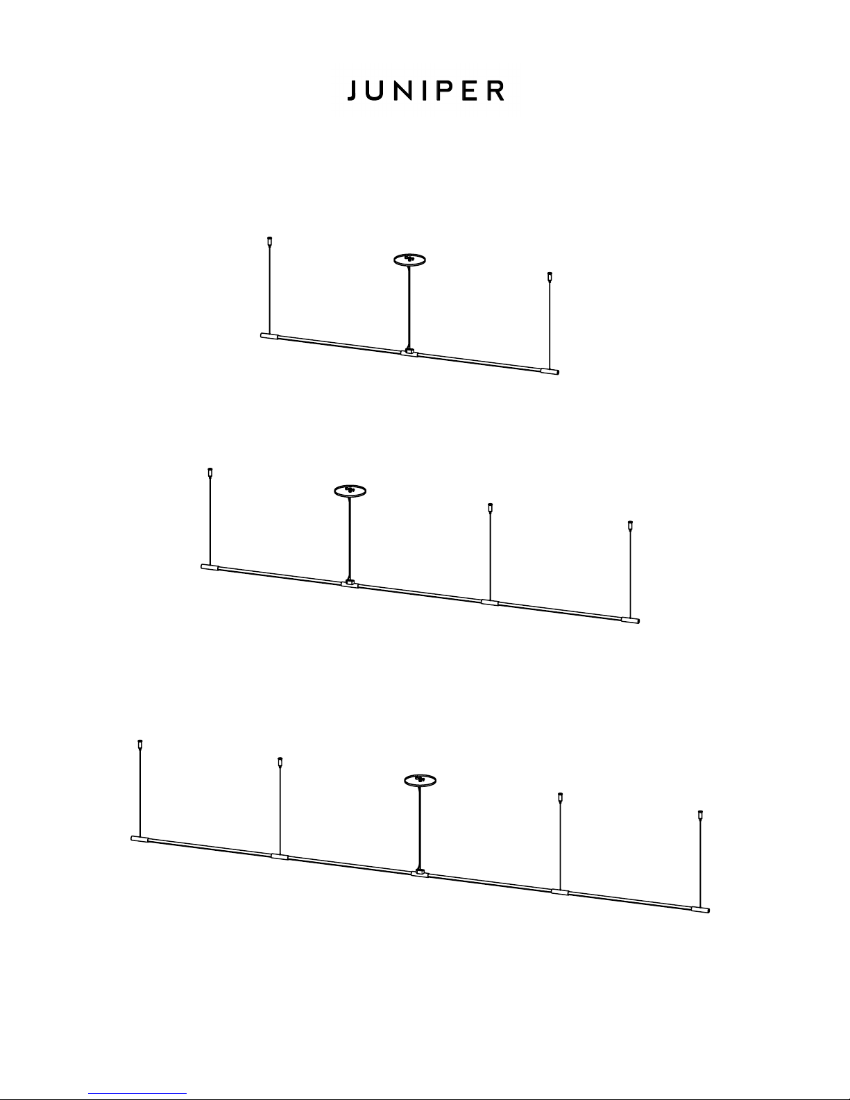
THIN Suspension
Center Power Feed
Remote Installation Guide
24" THES, 2 CONNECTED SECTIONS
1
24" THES, 3 CONNECTED SECTIONS
24" THES, 4 CONNECTED SECTIONS
SHOWN ARE EXAMPLES OF CONFIGURATION POSSIBLITIES. SPECIFIC FIXTURE CONFIGURATION MAY VARY.
Page 2
THIN SUSPENSION INSTALLATION GUIDE
A LICENSED ELECTRICIAN SHOULD PERFORM INSTALLATION.
DISCONNECT MAIN POWER AT THE SOURCE PRIOR TO INSTALLATION.
INSTRUCTIONS MEANT FOR A REMOTE CLASS 2 DRIVER.
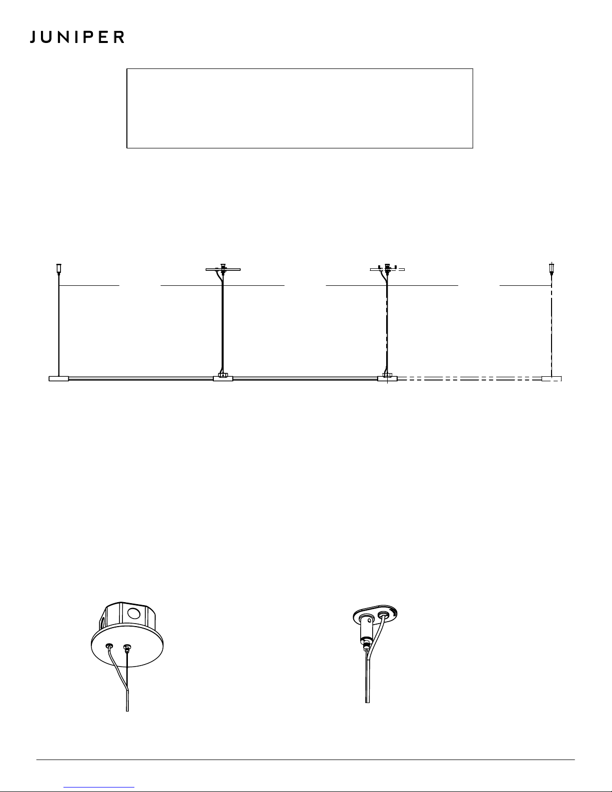
STEP 1: MARK MOUNTING POINTS
2
WARNING
Carefully mark the mounting points with a pencil or marker, using the spacing in Figure 1.
use a laser alignment/ measuring tool to ensure that mounting parts are properly distanced and fall on a straight line.
24" OR 36" 24" OR 36"
C
FIGURE 1
It is highly recommended to
24" OR 36"
A/BA/B
KEY
A
CENTER POWER SLEEVES
(SEE POWER FEED OPTIONS)
B
PASSTHROUGH SLEEVES
C
END SLEEVES
MOUNTED AT BOTH ENDS OF THE FIXTURE
MOUNTED BENEATH CANOPY PLATE OR MINI MOUNTING PLATE AT ANY LOCATION BETWEEN THE END SLEVES
.*
USED TO CONNECT SEGMENTS TOGETHER. MOUNTED IN BETWEEN CENTER POWER SLEEVES AND END SLEEVES
.
C
.
* In order to install the fixture with the canopy at either end of the fixture, please refer to "THIN Suspension Remote Installation
Guide" or contact Juniper for instructions.
POWER FEED OPTIONS
CANOPY PLATE
FOR FIXTURES WIRED TO A JUNCTION
BOX.
SEE
STEP 2A
AND WIRING INFORMATION.
FIGURE 2
WWW.JUNIPER-DESIGN.COM | INFO@JUNIPER-DESIGN.COM | +1 347 799-2915 | 68 33RD STREET, UNIT 11, BROOKLYN, NY 11232 WWW.JUNIPER-DESIGN.COM | INFO@JUNIPER-DESIGN.COM | +1 347 799-2915 | 68 33RD STREET, UNIT 11, BROOKLYN, NY 11232
FOR DETAILED INSTALLATION
FIGURE 3
MINI MOUNTING PLATE
FOR IN-CEILING WIRING AND FIXTURES
SUSPENDED FROM THE CEILING.
SEE
STEP 2B
AND WIRING INFORMATION.
FOR DETAILED INSTALLATION
Page 3

THIN SUSPENSION INSTALLATION GUIDE
STEP 2A: JUNCTION BOX COVER PLATE INSTALLATION INSTRUCTIONS
3
1
FIGURE 4
Remove gripper from the canopy
cover to release the crossbar.
AC - LINE - Black
4
AC - NEUTRAL - White
+
REMOTE
LED
DRIVER
INPUT
-
- 24VDC lead
from remote driver
Red
+
OUTPUT
Black
-
2 3
FIGURE 5
Attach the crossbar to the junction box
using provided screws.
Low voltage wires from LED driver
Connect the ground wire to
ground screw on crossbar.
+ 24VDC lead from remote driver
5
Press the
safety nut
upwards to
Unscrew
safety nut
pass aircraft
cable through
the gripper
FIGURE 6
Partly loosen safety nut on cable gripper.
Feed aircraft cable through the gripper.
Do this for all aircraft cable ends.
"+ RED"
"- BLACK"
Bushing
Strain relief
FIGURE 7
Pass power cable, through bushing and strain relief as shown. Connect wires
according to diagram (wire nuts provided).
adjusted for desired suspension height. Wires to and from the driver are not included.
6
Length of power cord should be
7
FIGURE 9
Install ceiling posts at all B and C mounting points using
provided screws. Screw grippers into ceiling posts.
Woodscrews are provided for default installation. Alternate
screws may be used at the recommendation of an electrician.
Use laser alignent/ measuring tool to ensure accurate
placement of the ceiling post.
Adjust aircraft cable length as needed. Press safety nut on
gripper to loosen aircraft cable. Tighten safety nut in completely
when finished.
assembled and desired suspension height is achieved.
Place wires inside junction box and screw
FIGURE 8
gripper into crossbar to attach canopy plate
to junction box.
FIGURE 10
Do not cut extra aircraft cable until full fixture is
WWW.JUNIPER-DESIGN.COM | INFO@JUNIPER-DESIGN.COM | +1 347 799-2915 | 68 33RD STREET, UNIT 11, BROOKLYN, NY 11232
Page 4

THIN SUSPENSION INSTALLATION GUIDE
STEP 2B: MINI MOUNTING PLATE INSTALLATION INSTRUCTIONS
4
1
3
"
4
1/2" HOLE
DRILL
FOR BUSHING
"A" MOUNTING POINT
FIGURE 11
Drill hole for bushing according to diagram.
4 5
Low voltage wires
to LED driver
2
INSTALL AT "A"
MOUNTING POINTS ONLY
INSTALL AT "B" & "C"
MOUNTING POINTS
FIGURE 12
Install using provided screws according
to diagram.
3
FIGURE 13
Partly unscrew safety nut
on gripper and feed
aircraft cables through.
FIGURE 14
Pass power cord through bushing and connect
to electrician-provided 18AWG in-wall rated
cable (recommended).
Screw grippers into ceiling posts. Adjust aircraft cable lengths as
needed. Press safety nut on gripper to release aircraft cable. Tighten
safety nut when finished.
fully assembled and desired suspension height is achieved.
FIGURE 15
Do not cut extra aircraft cable until fixture is
STEP 3: LIGHT TUBE INSTALLATIONS
The THIN Suspension fixture is designed with an innovative magnetic connection. Simply insert the light tubes into their sleeves for
electrical contact to be made.
O-Rings
3. Slide the end
sleeves onto the last
set of light tubes.
4. Space the O-rings apart
on the power sleeve along
the length of the cable to
constrain the power cord
to aircraft cable.
CARE INSTRUCTIONS
Brass will patina over
time like other natural
metals and regular care
is required in order to
retain the quality finish of
your THIN fixture for years
to come.
Gently wipe with a damp
cloth to remove dirt,
dust, and fingerprints.
Do not use any chemical
cleaning solution.
Use indoors only.
1. Reconnect main power
and insert light tubes into
the power end. Push light
tubes in carefully until they
illuminate.
Light Tube
FIGURE 16
2. Push following passthrough
sleeve onto illuminated light
tubes. Add light tubes and
sleeves as needed according
to your segment
configuration.
WWW.JUNIPER-DESIGN.COM | INFO@JUNIPER-DESIGN.COM | +1 347 799-2915 | 68 33RD STREET, UNIT 11, BROOKLYN, NY 11232
 Loading...