

Page 1

TCX1000 2-Degree 8-Channel Multiplexer
Quick Start Guide
About This Quick Start Guide . . . . . . . . . . . . . . . . . . . . . . . . . . . . . . . . . . . . . . . . . . . . . . . . . . . . . . . . . . . . . . . . . . . . . . . . . . . . . . . . 1
Step 1: Prepare Your Site for the TCX1000-2D8CMD . . . . . . . . . . . . . . . . . . . . . . . . . . . . . . . . . . . . . . . . . . . . . . . . . . . . . . . . . . . . . 2
Step 2: Unpack the TCX1000-2D8CMD . . . . . . . . . . . . . . . . . . . . . . . . . . . . . . . . . . . . . . . . . . . . . . . . . . . . . . . . . . . . . . . . . . . . . . . 2
Step 3: Mount the Chassis . . . . . . . . . . . . . . . . . . . . . . . . . . . . . . . . . . . . . . . . . . . . . . . . . . . . . . . . . . . . . . . . . . . . . . . . . . . . . . . . . . 2
Step 4: Install the TCX1000-2D8CMD in the Chassis . . . . . . . . . . . . . . . . . . . . . . . . . . . . . . . . . . . . . . . . . . . . . . . . . . . . . . . . . . . . 3
Step 5: Connect the TCX1000-2D8CMD . . . . . . . . . . . . . . . . . . . . . . . . . . . . . . . . . . . . . . . . . . . . . . . . . . . . . . . . . . . . . . . . . . . . . . 4
Safety Warnings Summary . . . . . . . . . . . . . . . . . . . . . . . . . . . . . . . . . . . . . . . . . . . . . . . . . . . . . . . . . . . . . . . . . . . . . . . . . . . . . . . . . 5
NEBS Compliance Statements . . . . . . . . . . . . . . . . . . . . . . . . . . . . . . . . . . . . . . . . . . . . . . . . . . . . . . . . . . . . . . . . . . . . . . . . . . . . . . 5
Compliance Statements for EMC Requirements . . . . . . . . . . . . . . . . . . . . . . . . . . . . . . . . . . . . . . . . . . . . . . . . . . . . . . . . . . . . . . . . 6
Canada . . . . . . . . . . . . . . . . . . . . . . . . . . . . . . . . . . . . . . . . . . . . . . . . . . . . . . . . . . . . . . . . . . . . . . . . . . . . . . . . . . . . . . . . . . . . . 6
European Community . . . . . . . . . . . . . . . . . . . . . . . . . . . . . . . . . . . . . . . . . . . . . . . . . . . . . . . . . . . . . . . . . . . . . . . . . . . . . . . . . 6
Israel . . . . . . . . . . . . . . . . . . . . . . . . . . . . . . . . . . . . . . . . . . . . . . . . . . . . . . . . . . . . . . . . . . . . . . . . . . . . . . . . . . . . . . . . . . . . . . . 6
Japan . . . . . . . . . . . . . . . . . . . . . . . . . . . . . . . . . . . . . . . . . . . . . . . . . . . . . . . . . . . . . . . . . . . . . . . . . . . . . . . . . . . . . . . . . . . . . . . 6
United States . . . . . . . . . . . . . . . . . . . . . . . . . . . . . . . . . . . . . . . . . . . . . . . . . . . . . . . . . . . . . . . . . . . . . . . . . . . . . . . . . . . . . . . . 6
TCX Series Documentation and Release Notes . . . . . . . . . . . . . . . . . . . . . . . . . . . . . . . . . . . . . . . . . . . . . . . . . . . . . . . . . . . . . . . . . 6
Requesting Technical Support . . . . . . . . . . . . . . . . . . . . . . . . . . . . . . . . . . . . . . . . . . . . . . . . . . . . . . . . . . . . . . . . . . . . . . . . . . . . . . 7
Self-Help Online Tools and Resources . . . . . . . . . . . . . . . . . . . . . . . . . . . . . . . . . . . . . . . . . . . . . . . . . . . . . . . . . . . . . . . . . . . . 7
Opening a Case with JTAC . . . . . . . . . . . . . . . . . . . . . . . . . . . . . . . . . . . . . . . . . . . . . . . . . . . . . . . . . . . . . . . . . . . . . . . . . . . . . . 7
About This Quick Start Guide
This Quick Start Guide contains information you need to install and connect the Juniper Networks TCX1000 2-Degree, 8-Channel
Multiplexer. For complete installation instructions, see the TCX1000 Programmable ROADM Hardware Guide at
https://www.juniper.net/documentation/, or scan the QR code at the bottom of the page to go directly to the hardware guide.
WARNING: This Quick Start Guide contains a summary of safety warnings in “Safety Warnings Summary” on page 5.
For a complete list of warnings for the TCX1000-2D8CMD module, including translations, see the TCX1000
Programmable ROADM Hardware Guide at https://www.juniper.net/documentation/.
The TCX1000-2D8CMD is a standalone passive splitter that acts as a simple port multiplier. It is a rack-mounted module that is
installed alongside the TCX1000-RDM20.
Page 2

TCX1000 2-Degree 8-Channel Multiplexer Quick Start Guide
Step 1: Prepare Your Site for the TCX1000-2D8CMD
Beforeinstalling the TCX1000-2D8CMDmodule,makesureyoursitemeets all power, environmental, and clearancerequirements.
NOTE: To mount the TCX1000-2D8CMD in a rack, you need the TCX1000-RCK-1 kit. This kit is separately orderable.
Ensure that you have the following parts and tools available to install the TCX1000-2D8CMD:
•
Electrostatic discharge (ESD) grounding strap (not provided).
•
Screwdriver appropriate for the rack-mounting screws (not provided).
•
TCX1000-RCK-1 kit (separately orderable), which includes these items:
•
Chassis to mount the TCX1000-2D8CMD
•
Four self-tapping bolts to secure the chassis to the rack
•
Two 19-in. front mounting brackets (preinstalled on the chassis)
•
Two 21-in. and two 23-in. mounting brackets
Step 2: Unpack the TCX1000-2D8CMD
For detailed instructions on how to unpack the box and verify the parts received for the TCX1000-2D8CMD, see the TCX1000
Programmable ROADM Hardware Guide at https://www.juniper.net/documentation/.
Step 3: Mount the Chassis
To mount the TCX1000-RCK-1 chassis on two posts in a rack using the 19-in. mounting brackets:
NOTE: The 19-in. front brackets are attached to the chassis when they are shipped. If you want to attach the 21-in.
or 23-in. brackets, unscrew the 19-in. brackets from the chassis, and attach the 21-in. or 23-in. brackets by using the
same screws.
NOTE: This procedure requires two persons. Do not attempt to do it alone.
1. Attach an ESD grounding strap to your bare wrist and to a site ESD point.
NOTE: Place the rack in its permanent location, allowing adequate clearance for airflow and maintenance, and
secure it to the building structure.
2. Have one person grasp both sides of the chassis, lift it, and position it in the rack so that the front brackets are aligned with
the rack holes. See Figure 1.
3. Have a second person secure the front of the chassis to the rack using four mounting screws (and cage nuts and washers if
your rack requires them). Tighten the screws. See Figure 1.
Copyright © 2018, Juniper Networks, Inc.2
Page 3
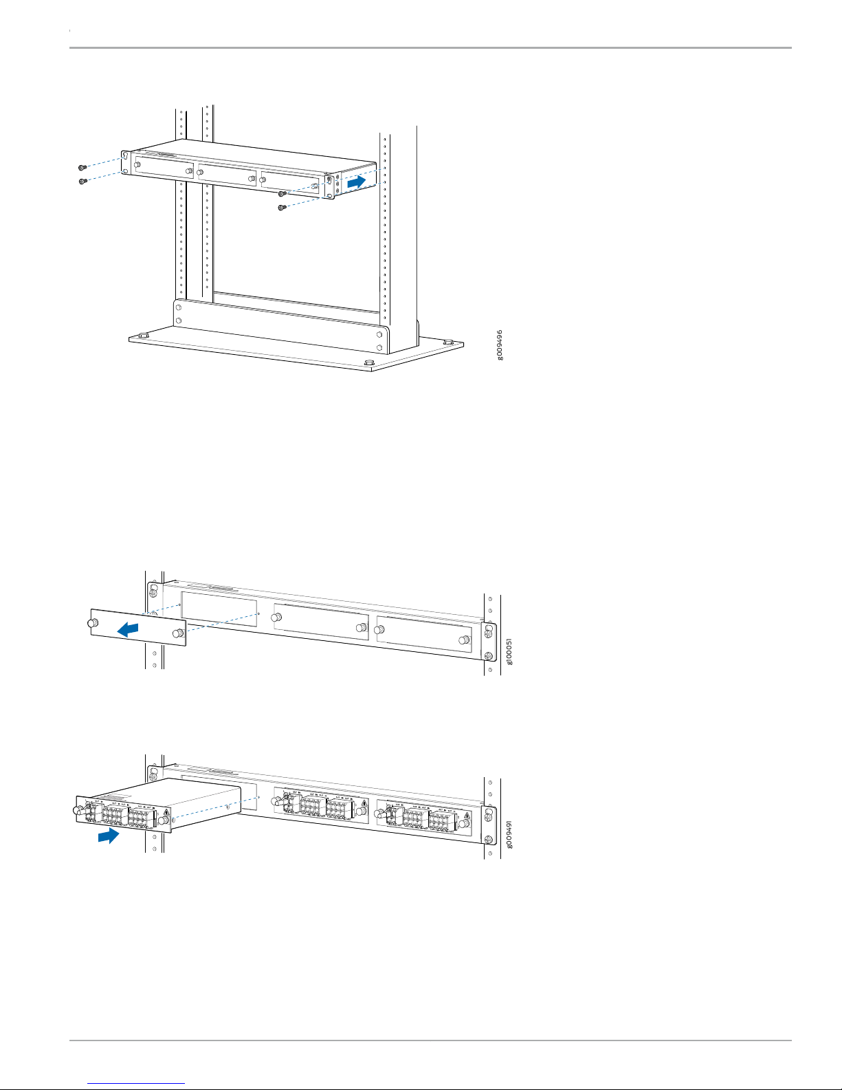
Figure 1: Installing the Chassis on a Rack
g009496
g100051
g009491
Step 4: Install the TCX1000-2D8CMD in the Chassis
TCX1000 2-Degree 8-Channel Multiplexer Quick Start Guide
To install the TCX1000-2D8CMD in the chassis:
1. Attach the ESD grounding strap to your bare wrist and to a site ESD point.
2. Remove the blank cover by pulling the knobs of the snap latch (located on either side) and pulling the cover out. See Figure 2.
Figure 2: Removing the Blank Cover from the Module Slot
3. Lift the TCX1000-2D8CMD and carefully align it with the slot in the chassis, as shown in Figure 3.
Figure 3: Installing the TCX1000-2D8CMD in the Chassis
4. Slide the TCX1000-2D8CMD until it is fully seated in the slot. Push the knobs in fully on the snap latch (located on either side)
to lock in the TCX1000-2D8CMD.
5. Install additional modules if needed by following the same steps. You can install up to three modules in the chassis.
3Copyright © 2018, Juniper Networks, Inc.
Page 4

g009494
TCX1000 2-Degree 8-Channel Multiplexer Quick Start Guide
Step 5: Connect the TCX1000-2D8CMD
The TCX1000-2D8CMD has optical connectors to which you can connect fiber-optic cables.
Before you connect a fiber-optic cable to a TCX1000-2D8CMD, ensure that you have taken the necessary precautions for safe
handling of lasers. See the Laser Safety Warnings for Class 1M Juniper Networks Devices in the TCX1000 Programmable ROADM
Hardware Guide.
To connect a fiber-optic cable to an optical connector in the TCX1000-2D8CMD:
1. Remove any protective caps from the fiber-optic cable. Save the caps. Also, inspect the fiber-optic cable with a scope, and
use a fiber-cleaning device to clean the connector prior to insertion.
WARNING: Do not look directly into a fiber-optic connector or into the ends of fiber-optic cables. Fiber-optic
transceivers and fiber-optic cables connected to transceivers emit laser light that can damage your eyes.
WARNING: Class 1M laser product.
WARNING: Do not stare into the laser beam or view it directly with optical instruments even if the interface has
been disabled.
2. Remove the rubber safety caps from the optical connectors on the TCX1000-2D8CMD. Save the caps. Inspect the fiber-optic
cable with a scope, or use a fiber-cleaning device to clean the connector prior to inserting the fiber-optic cable into the Line
0 (L0) OUT port of the TCX1000-2D8CMD. See Figure 4.
NOTE: The TCX1000-2D8CMD is shipped with an optical terminator preinstalled in the Line 1 out (L1 OUT) port.
The optical terminator is preinstalled to prevent optical power from being reflected back into the transponder
transmitter in cases where the L1 out port is not in use. If you plan to use only one of the Line ports, then you should
use the L0 port (the default port). If you plan to use both of the Line ports, then the optical terminator must be
removedfromthe L1 OUT port, and the connector must be inspected and cleaned prior to connecting the fiber-optic
cable.
Figure 4: Connecting the Fiber-Optic Cable
3. Inspect the other end of the fiber-optic cable with a scope, or use a fiber-cleaning device to cleanthe connectorbefore inserting
it into any of the universal ports (U0 to U19) of the TCX1000-RDM20.
4. Secure the cables so that they do not support their own weight. Place excess cable out of the way in a neatly coiled loop.
Placing fasteners on a loop helps cables maintain their shape.
Copyright © 2018, Juniper Networks, Inc.4
Page 5

TCX1000 2-Degree 8-Channel Multiplexer Quick Start Guide
CAUTION: Do not bend fiber-optic cables beyond their minimum bend radius. Bending the cables beyond their
minimum bend radius can damage the cables and cause problems that are difficult to diagnose.
CAUTION: Do not let fiber-optic cables hang free from the connector. Do not allow fastened loops of cables to
dangle, which stresses the cables at the fastening point.
NOTE: For instructions about connecting the TCX1000-2D8CMD to other devices, see the TCX1000Programmable
ROADM Hardware Guide.
Safety Warnings Summary
CAUTION: Before removing or installing the TCX1000-2D8CMD, attach an ESD strap to an ESD point, and place the
other end of the strap around your bare wrist. Failure to use an ESD strap could result in damage to the equipment.
•
Permit only trained and qualified personnel to install or replace TCX1000-2D8CMD components.
•
Perform only the procedures described in this Quick Start Guide and the TCX1000 documentation. Other services must be
performed only by authorized service personnel.
•
Before installing the device, read the planning instructions in the TCX1000 Programmable ROADM Hardware Guide to make
sure that the site meets environmental requirements for the TCX1000-2D8CMD.
•
If the rack or cabinet has stabilizing devices, install them in the rack before mounting or servicing the TCX1000-2D8CMD in the
rack or cabinet.
•
Before installing or after removing an electrical component, always place it component-side up on a flat antistatic mat or in
an electrostatic bag.
•
Do not work on the TCX1000-2D8CMD or connect or disconnect cables during electrical storms.
•
Before working on equipment that is connected to power lines, remove jewelry, including rings, necklaces, and watches. Metal
objects heat up when connected to power and ground and can cause serious burns or become welded to the terminals.
NEBS Compliance Statements
•
The equipment is suitable for installation as part of the Common Bonding Network (CBN).
•
The equipment is suitable for installations in Network Telecommunication Facilities.
5Copyright © 2018, Juniper Networks, Inc.
Page 6

TCX1000 2-Degree 8-Channel Multiplexer Quick Start Guide
Compliance Statements for EMC Requirements
•
Canada on page 6
•
European Community on page 6
•
Israel on page 6
•
Japan on page 6
•
United States on page 6
Canada
CAN ICES-3 (A)/NMB-3(A)
European Community
This is a Class A product. In a domestic environment, this product might cause radio interference in which case the user might be
required to take adequate measures.
Israel
Translation from Hebrew—Warning: This product is Class A. In residential environments, the product might cause radio interference,
and in such a situation, the user might be required to take adequate measures.
Japan
The preceding translates as follows:
This is a Class A product based on the standard of the Voluntary Control Council for Interference by Information Technology
Equipment (VCCI). If this product is used near a radio or television receiver in a domestic environment, it might cause radio
interference. Install and use the equipment according to the instruction manual. VCCI-A.
United States
The hardware equipment has been tested and found to comply with the limits for a Class A digital device, pursuant to Part 15 of
the FCC Rules. These limits are designed to provide reasonable protection against harmful interference when the equipment is
operated in a commercial environment. This equipment generates, uses, and can radiate radio frequency energy and, if not
installed and used in accordance with the instruction manual, might cause harmful interference to radio communications.
Operation of this equipment in a residential area is likely to cause harmful interference in which case the user will be required to
correct the interference at his own expense.
TCX Series Documentation and Release Notes
For a list of the complete TCX series documentation including the release notes, see https://www.juniper.net/documentation/
en_US/release-independent/tcx/information-products/pathway-pages/index.html.
To obtain the most current version of all Juniper Networks technical documentation, see the product documentation page on
the Juniper Networks website at https://www.juniper.net/documentation/.
Copyright © 2018, Juniper Networks, Inc.6
Page 7

TCX1000 2-Degree 8-Channel Multiplexer Quick Start Guide
Requesting Technical Support
Technical product support is available through the Juniper Networks Technical Assistance Center (JTAC). If you are a customer
with an active J-Care or Partner Support Service support contract, or are covered under warranty, and need postsales technical
support, you can access our tools and resources online or open a case with JTAC.
•
JTAC policies—For a complete understanding of our JTAC procedures and policies, review the JTAC User Guide located at
https://www.juniper.net/us/en/local/pdf/resource-guides/7100059-en.pdf.
•
Product warranties—For product warranty information, visit https://www.juniper.net/support/warranty/.
•
JTAC Hours of Operation—The JTAC centers have resources available 24 hours a day, 7 days a week, 365 days a year.
Self-Help Online Tools and Resources
For quick and easy problem resolution, Juniper Networks has designed an online self-service portal called the Customer Support
Center (CSC) that provides you with the following features:
•
Find CSC offerings: https://www.juniper.net/customers/support/
•
Find product documentation: https://www.juniper.net/documentation/
•
Find solutions and answer questions using our Knowledge Base: https://kb.juniper.net/
•
Download the latest versions of software and review release notes: https://www.juniper.net/customers/csc/software/
•
Search technical bulletins for relevant hardware and software notifications: https://kb.juniper.net/InfoCenter/
•
Join and participate in the Juniper Networks Community Forum: https://www.juniper.net/company/communities/
•
Open a case online in the CSC Case Management tool: https://www.juniper.net/cm/
To verify service entitlement by product serial number, use our Serial Number Entitlement (SNE) Tool:
https://entitlementsearch.juniper.net/entitlementsearch/
Opening a Case with JTAC
You can open a case with JTAC on the Web or by telephone.
•
Use the Case Management tool in the CSC at https://www.juniper.net/cm/.
•
Call 1-888-314-JTAC (1-888-314-5822 toll-free in the USA, Canada, and Mexico).
For international or direct-dial options in countries without toll-free numbers, visit us at
https://www.juniper.net/support/requesting-support.html.
Juniper Networks, the Juniper Networks logo, Juniper, and Junos are registered trademarks of Juniper Networks, Inc. and/or its affiliates in the United States
and other countries. All other trademarks may be property of their respective owners. Juniper Networks assumes no responsibility for any inaccuracies in this
document. Juniper Networks reserves the right to change, modify, transfer, or otherwise revise this publication without notice. Copyright © 2018 Juniper
Networks, Inc. All rights reserved. Part Number: 530-084956 Rev. 01, April 2018.
 Loading...