

Page 1

T320 Internet Router and T640 Internet
Routing Node Control Board (T-CB)
Installation Instr uctions
12 November 2004
Part No: 530-012185-01
Revision 2
This document describes how to remove and replace a Control Board (T-CB) in a
T320 Internet router and a T640 Internet routing node.
Contents
T-CB Description ............... ................ ................ ................ ..... 2
T-CB Components........ ................ ................ .................. ......... 3
Tools and Parts Required........................................................... 4
Replacing a T-CB ............ ................ ................ ................ ....... 4
Removing a T-CB............................................................... 4
Installing a T-CB ............................................................... 5
List of Technical Publications ............. ................ ................ ......... 6
Requesting Support................................................................. 8
Revision History ....... ................ .................. ................ ........... 9
1
Page 2
T320 Internet Router and T640 Internet Routing Node Control Board (T-CB) Installation Instructions
T-CB Description
Each T-CB works with an adjacent Routing Engine to provide control
and monitoring functions for the routing platform (see Figure 1). T hese
functions include determining Routing Engine mastership; controlling power
and reset for the other routing platform components; monitoring and
controlling fan speed; and monitoring system status.
You can install one or two T-CBs in the routing platform. The T-CBs install
into the upper rear of the chassis in the slots labeled
T-CB-0 and T-CB-1). If two T-CBs are installed, one functions as the
to as
master T-CB and the other as its backup. If the master fails or is removed,
the backup restarts and becomes the master.
CB0 and CB1 (referred
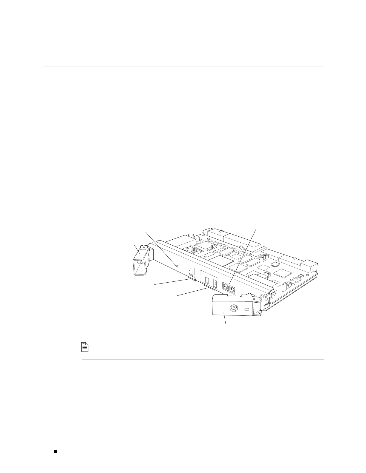
Figure 1: T-CB
EachT-CBrequiresaRoutingEnginetobeinstalledintheadjacentslot.
T-CB-0
installs above RE0,andT-CB-1 installs below RE1.AT-CBdoesnotfunction
if a Routing Engine is not present in the adjacent slot.
T-CBs are hot-pluggable.
Extractor clip
Online/offline
button
LEDs
M/S and chassis
ID switches
O
N
LIN
E
O
F
F
L
IN
Control Board - T
/
E
M
F
A
I
L
O
K
A
S
T
E
R
M
U
L
T
I C
H
A
S
S
IS
M
O
M
C
D
H
Y
E
A
E
S
LL
S
IS
O
G
W
ID
S
R
=
E
E
A
N
U
=
X
1
Extractor clip
10
M
b
0
0M
b
C
IP
Control
plane ports
g002130
NOTE: The T-CB requires JUNOS software Release 7.0 or later.
2 T-CB Des cription
Page 3

T-CB Components
Each T-CB consists of the following components:
100-MB Ethernet switch. This switch is used for intermodule communication.
PCI bus to the Routing Engines.
Processor subsystem (SPMB).
Three LEDs, located on the T-CB faceplate. These indicate the status of the
T-CB. Table 1 describes the functions of the T-CB LEDs.
Online/offline button, located on the T-CB faceplate. This button is
nonfunctional.
Two configuration switches, located on the T-CB faceplate.
NOTE: The M/S and CHASSIS ID switches on the T-CB faceplate must always be set to
S and 0 in a standalone routing platform.
If a T640 routing node is connected to a TX Matrix platform, these switches must
be set to
M and the chassis identifier (ID) of the routing node. In this case, both
T-CBs must have the same chassis ID. For more information, see the TX Matrix
Platform Hardware Guide.
Table 1: T-CB LEDs
Two RJ-45 ports labeled AUX and CIP on the T-CB faceplate. These ports are not
used in a standalone routing platform. Only the
CIP port is used in a T640
routing node connected to a TX Matrix platform. For more information, see
the TX Matrix Platform Hardware Guide.
Label Color State Description
MASTER Blue On steadily T-CB is functioning as the master.
FAI L Amber On steadily T-CB has failed.
Green
On steadily T-CB is online and is functioning normally.OK
Blinking T-CB is pow
ering up, but not online.
T-CB Components 3
Page 4

T320 Internet Router and T640 Internet Routing Node Control Board (T-CB) Installation Instructions
Tools and Parts Required
To replace a T-CB, you need the following tools:
Phillips (+) screwdriver, number 2
ESD wrist strap with cable
Electrostatic bag or antistatic mat
Blank panels to cover any slots not occupied by a component
Replacing a T-CB
The T-CBs are hot-pluggable. If the routing platform contains a redundant host
subsystem, the T-CB and the Routing Engine are hot-removable and hot-insertable.
Before you replace a T-CB or a Routing Engine, you must take the host subsystem
offline(seetheT320 Internet Router Hardware Guide or the T640 Internet Routing
Node Hardware Guide). To replace a T-CB, use the following procedures:
Removing a T-CB
NOTE: The figures in these procedures show the T640 routing node for reference.
Removing a T-CB on page 4
InstallingaT-CBonpage 5
The routing platform can have one or two T-CBs. They are located in
the upper rear of the chassis in the slots marked
CB0 and CB1.Each
T-CB weighs approximately 5 lb (2.3 kg).
To remove a T-CB, follow this procedure (see Figure 2):
1. Place an electrostatic bag or antistatic mat on a flat, stable surface.
2. Attach an electrostatic discharge (ESD) grounding strap to your bare wrist
and connect the strap to one of the ESD points on the chassis. For more
information about ESD, see the T320 Internet Router Hardware Guide or the
T640 Internet Routing Node Hardware Guide.
3. Check whether the T-CB is functioning as the backup or as the master. If
necessary, take the host subsystem offline as described in the T320 Internet
Router Hardware Guide or the T640 Internet Routing Node Hardware Guide.
4. If applicable, disconnect the cable plugged into the port labeled CIP.
5. Loosen the captive screws (using a Phillips (+) screwdriver, number 2) on the
ejector handles on both sides of the T-CB faceplate.
4 Removing a T-CB
Page 5

Figure 2: Removing a T-CB
6. Flip the ejector handles outward to unseat the T-CB.
7. Grasp the ejector handles and slide the T-CB about halfway out of the chassis.
8. Place one hand underneath the T-CB to support it and slide it completely
outofthechassis.
9. PlacetheT-CBontheantistaticmat.
10. If you are not replacing the T-CB now, install a blank panel over the empty slot.
Installing a T-CB
g002187
To install a T-CB, follow this procedure (see Figure 3):
1. Attach an electrostatic discharge (ESD) grounding strap to your bare wrist
and connect the strap to an approved site ESD grounding point. For more
information about ESD, see the T320 Internet Router Hardware Guide or the
T640 Internet Routing Node Hardware Guide.
2. Ensure the ejector handles are not flush with the faceplate. If necessary, loosen
the captive screws and flip the ejector handles outward.
3. Carefully align the sides of the T-CB with the guides inside the chassis.
4. Slide the T-CB into the chassis, c arefully ensuring that it is correctly aligned.
5. Grasp both ejector handles and press them inward to seat the T-CB.
6. Tighten the captive screws on the ejector handles, using a Phillips (+)
screwdriver, number 2.
7. If applicable, reconnect the cable previously plugged into the CIP port.
Installing a T-CB 5
Page 6

T320 Internet Router and T640 Internet Routing Node Control Board (T-CB) Installation Instructions
8. If power is applied to the T-CB and its corresponding Routing Engine is
functioning normally, the T-CB comes online automatically. To verify that the
T-CB is functioning normally, check the LEDs on its faceplate. The green
should light steadily a few minutes after the T-CB is installed. If the
lit steadily, remove and install the T-CB again (see “Removing a T-CB” on page
4 and “Installing a T-CB ” on page 5 ). If the
FAI L LED still lights steadily, the
T-CB is not functioning properly. Contact your customer support representative.
To check the status of the T-CB, use the CLI command:
user@host> show chassis environment cb
Figure 3: Reinstalling a T-CB
OK LED
FAI L LED is
List of Technical Publications
Table 2 lists the software and hardware guides and release notes for Juniper
Networks routing platforms that use the JUNOS Internet software and describes
the contents of each book.
Table 2: Juniper Networks Technical Documentation
Book Description
JUNOS for J-series, M-series, and T-series Routing Platforms Configuration Guides
Feature Guide
System Basics
Provides a detailed explanation and configuration examples for
several of the most complex features in the JUNOS software.
Provides an overview of the JUNOS software and describes how to
install and upgrade the software. This manual also describes how
to configure system management functions and how to configure
the chassis, including user accounts, passwords, and redundancy.
g002188
6 List of Technical Publications
Page 7

Book Description
Network Interfaces and Class of Service
Provides an overview of the network interface and class-of-service
functions of the JUNOS software and describes how to configure
the network interfaces on the router.
MPLS Applications
Provides an overview of traffic engineering concepts and describes
how to configure traffic engineering protocols.
Multicast Protocols
Provides an overview of multicast concepts and describes how to
configure multicast routing protocols.
Network Management
Provides an overview of network management concepts and
describes how to configure various network management features,
such as SNMP, accounting options, and cflowd.
Policy Framework
Provides an overview of policy concepts and describes how to
configure routing policy, firewall filters, and forwarding options.
Routing Protocols
Provides an overview of routing concepts and describes how to
configure routing, routing instances, and unicast routing protocols.
Services Interfaces
Provides an overview of the services interfaces functions of the
JUNOS software and describes how to configure the services
interfaces on the router.
VPNs
Provides a
n overview and describes how to configure Layer 2 and
Layer 3 virtual private networks (VPNs), virtual private LAN service
(VPLS), and Layer 2 circuits. Provides configuration examples.
JUNOS Refe
Network and Services Interfaces Command
Reference
rences
Describes the JUNOS Internet software operational mode
commands you use to monitor and troubleshoot network and
services interfaces on Juniper Networks routing platforms.
Protocols, Class of Service, and System Basics
Command Reference
Describes the JUNOS Internet software operational mode
commands you use to monitor and troubleshoot most aspects of
Juniper Networks routing platforms.
System Log Messages Reference
Describes how to access and interpret system log messages
generated by JUNOS software modules and provides a reference
page for each message.
JUNOScript API Documentation
JUNOScript API Guide
Describes how to use the JUNOScript application programming
interface (API) to monitor and configure Juniper Networks routers.
JUNOScript API Configuration Reference
Provides reference pages for the configuration tags in the
JUNOScript API.
JUNOScript API Operational Reference
Provides reference pages for the operational tags in the JUNOScript
API.
JUNOS Comprehensive Index and Glossary
Comprehensive Index and Glossary
Provides a complete index of all JUNOS Internet software books
and the JUNOScript API Guide. Also provides a comprehensive
glossary .
Hardware Documentation
Hardware Guide
Describes how to install, maintain, and troubleshoot routers and
router components. Each platform has its own hardware guide.
PIC Guide
Describes the router Physical Interface Cards (PICs). Each router
platform has its own PIC guide.
List of Technical Publications 7
Page 8

T320 Internet Router and T640 Internet Routing Node Control Board (T-CB) Installation Instructions
Book Description
JUNOScope Documentation
JUNOScope Software User Guide
J-series Ser vices Router Documentation
J-series Services Router User Guide
Release Notes
JUNOS Internet Software Release Notes
Hardware Release Notes
JUNOScope Software Release Notes
J-series Services Router Release Notes
Describes the JUNOScope software graphical user interface (GUI),
how to install and administer the software, and how to use the
software to manage router configuration files and monitor router
operations.
Contains instructions for installing, configuring, and managing a
J-series Services Router. The guide explains how to prepare your
site for installation, unpack and install the hardware, power on the
router, configure secure routing, monitor network operations, and
perform routine maintenance.
Provide a summary of new features for a particular software
release. Software release notes also contain corrections and
updates to published JUNOS and JUNOScript manuals, provide
information that might have been omitted from the manuals, and
describe upgrade and downgrade procedures.
Describe the available documentation for the router platform
and summarize known problems with the hardware and
accompanying software. Each platform has its own release notes.
Contain corrections and updates to the published JUNOScope
manual, provide information that might have been omitted from
the manual, and describe upgrade and downgrade procedures.
Briefly describe Services Router features, identify known hardware
problems, and provide upgrade and downgrade instructions
Requesting Suppor t
For technical support, open a support case using the Case Manager l ink at
http://www.juniper.net/suppor t/ or call 1-888-314-JTAC (within the United States) or
1-408-745-9500 (outside the United States).
If you are reporting a hardware or software problem, issue the following command
from the CLI before contacting support:
user@host>request support information | save
filename
To provide a core file to Juniper Networks for analysis, compress the file with
the
gzip utility, rename the file to include your company name, and copy it to
ftp.juniper.net:pub/incoming. Then send the filename, along with software version
information (the output of the
show version command) and the configuration, to
support@juniper.net.
For documentation issues, fill out the bug report form located at
http://www.juniper.net/techpubs/docbug/docbugrepor t.html.
8 Requesting S uppor t
Page 9

Revision History
12 November 2004—Revision 2. Added JUNOS software requirement, and updated
support section.
12 November 2004—Revision 1.
Copyright © 2004, Juniper Networks, Inc. All righ ts reserved.
Juniper Networks, the Juniper Networks logo, NetScreen, NetS creen Technologies, the NetScreen logo, NetScreen-Global Pro, ScreenOS, and
GigaScreen are registered trademarks of Juniper Networks, Inc. in the United States and other count ries.
The following are trademarks of Juniper Networks, Inc.: ERX, ESP, E-series, Instant Virtual Extranet, Internet Processor, J2300, J4300, J6300, J-Prote ct,
J-series,J-Web,JUNOS,JUNOScope,JUNOScript,JUNOSe,M5,M7i,M10,M10i,M20,M40,M40e,M160,M320,M-series,MMD,NetScreen-5GT,
NetScreen-5XP, Net Screen-5X T, NetScreen-25, NetScreen-50, NetScreen-204, NetS creen-208, NetScreen-500, N etScreen-5200, NetScreen-5400,
NetScreen-IDP 10, NetScreen-IDP 100, NetScreen-IDP 500, NetScreen-Remote Security Client, NetScreen-Remote V PN Client, NetScreen-SA 1000 Series,
NetScreen-SA 3000 Series, NetScreen-SA 5000 Series, NetScreen-SA Central Manager, NetScreen Secure Access, NetScreen-SM 3000, NetScreen-Security
Manager, NMC-RX, SDX, Stateful Signature, T320, T64 0, T-series, and TX Matrix. All other tradem arks, service marks, registered trademarks, or registered
service marks are the property of their respective owners. All specifications are subject to change without notice. Jun iper Networks assum es no responsibility
for any inaccuracies in this document. Juniper Networks reserves the right to change, modify, transfer, or otherwise rev ise this publication withoutnotice.
Requesting Support 9
 Loading...