

Page 1

TCA8000 and TCA8500 Timing Server
Installation and Configuration Guide
Modified: 2017-06-23
Copyright © 2017, Juniper Networks, Inc.
Page 2

Juniper Networks, Inc.
1133 Innovation Way
Sunnyvale, California 94089
USA
408-745-2000
www.juniper.net
Juniper Networks, Junos, Steel-Belted Radius, NetScreen, and ScreenOS are registered trademarks of Juniper Networks, Inc. in the United
States and other countries. The Juniper Networks Logo, the Junos logo, and JunosE are trademarks of Juniper Networks, Inc. All other
trademarks, service marks, registered trademarks, or registered service marks are the property of their respective owners.
Juniper Networks assumes no responsibility for any inaccuracies in this document. Juniper Networks reserves the right to change, modify,
transfer, or otherwise revise this publication without notice.
TCA8000 and TCA8500 Timing Server Installation and Configuration Guide
Copyright © 2017, Juniper Networks, Inc.
All rights reserved.
Revision History
June 2017—Release 3.8.0.
The information in this document is current as of the date on the title page.
YEAR 2000 NOTICE
Juniper Networks hardware and software products are Year 2000 compliant. Junos OS has no known time-related limitations through the
year 2038. However, the NTP application is known to have some difficulty in the year 2036.
END USER LICENSE AGREEMENT
The Juniper Networks product that is the subject of this technical documentation consists of (or is intended for use with) Juniper Networks
software. Use of such software is subject to the terms and conditions of the End User License Agreement (“EULA”) posted at
http://www.juniper.net/support/eula.html. By downloading, installing or using such software, you agree to the terms and conditions of
that EULA.
Copyright © 2017, Juniper Networks, Inc.ii
Page 3

Table of Contents
About the TCA8000 and TCA8500 Timing Server . . . . . . . . . . . . . . . . . . . . . xv
Documentation Conventions . . . . . . . . . . . . . . . . . . . . . . . . . . . . . . . . . . . . . . xv
Requesting Technical Support . . . . . . . . . . . . . . . . . . . . . . . . . . . . . . . . . . . . . xv
Self-Help Online Tools and Resources . . . . . . . . . . . . . . . . . . . . . . . . . . . xvi
Opening a Case with JTAC . . . . . . . . . . . . . . . . . . . . . . . . . . . . . . . . . . . . . xvi
Part 1 TCA8000 and TCA8500 Timing Server Overview
Chapter 1 TCA8000 and TCA8500 Timing Server Description . . . . . . . . . . . . . . . . . . . . 3
TCA8000 and TCA8500 Timing Server Description . . . . . . . . . . . . . . . . . . . . . . . . 3
TCA8000 and TCA8500 Chassis Overview . . . . . . . . . . . . . . . . . . . . . . . . . . . . . . . 3
Part 2 Installing and SettingUpaTCA8000 or TCA8500TimingServer
Chapter 2 Installing and Setting Up a TCA8000 or TCA8500 Timing Server . . . . . . . . 11
Unpacking the TCA8000 or TCA8500 Timing Server . . . . . . . . . . . . . . . . . . . . . . . 11
Requirements for Installing a TCA8000 or TCA8500 Timing Server . . . . . . . . . . . 11
Reserving an IP Address for the TCA8000 or TCA8500 Timing Server . . . . . . . . . 12
Installing the TCA8000 or TCA8500 Timing Server . . . . . . . . . . . . . . . . . . . . . . . . 12
Recommendations for Mounting the Antenna (TCA8000 or TCA8500 Timing
Server) . . . . . . . . . . . . . . . . . . . . . . . . . . . . . . . . . . . . . . . . . . . . . . . . . . . . . . . . 12
Optimal GPS Antenna Mounting Conditions . . . . . . . . . . . . . . . . . . . . . . . . . . 13
Minimal TCA8000 or TCA8500 Timing Server Installation Conditions . . . . . 13
Mounting the Antenna . . . . . . . . . . . . . . . . . . . . . . . . . . . . . . . . . . . . . . . . . . . . 13
Changing the Password of Admin User Account . . . . . . . . . . . . . . . . . . . . . . . . . . . 14
Assigning an IP Address to the TCA8000 or TCA8500 Timing Server . . . . . . . . . 16
Visually Testing the TCA8000 or TCA8500 Timing Server With GPS . . . . . . . . . . 17
Verifying the Product T1/E1 Interface Support . . . . . . . . . . . . . . . . . . . . . . . . . . . . . 18
Part 3 Configuring and Upgrading the TCA8000 or TCA8500 Timing
Server
Chapter 3 Configuring a TCA8000 or TCA8500 Timing Server . . . . . . . . . . . . . . . . . . . 21
TCA User Accounts Overview . . . . . . . . . . . . . . . . . . . . . . . . . . . . . . . . . . . . . . . . . . 21
Guidelines for User Account Management . . . . . . . . . . . . . . . . . . . . . . . . . . . 22
Dynamic SSL Certificate Overview . . . . . . . . . . . . . . . . . . . . . . . . . . . . . . . . . . . . . 23
Accessing the User Interface . . . . . . . . . . . . . . . . . . . . . . . . . . . . . . . . . . . . . . . . . . 23
Requirements for Using the Graphical User Interface . . . . . . . . . . . . . . . . . . . . . . 24
Accessing the Graphical User Interface . . . . . . . . . . . . . . . . . . . . . . . . . . . . . . . . . . 24
Changing/Resetting the Login Password for Admin User . . . . . . . . . . . . . . . . . . . 28
Changing the IP Address . . . . . . . . . . . . . . . . . . . . . . . . . . . . . . . . . . . . . . . . . . . . . 30
iiiCopyright © 2017, Juniper Networks, Inc.
Page 4

TCA8000 and TCA8500 Timing Server Installation and Configuration Guide
Setting Precision Time Protocol (PTP) Parameters . . . . . . . . . . . . . . . . . . . . . . . . 33
Setting NTP Parameters . . . . . . . . . . . . . . . . . . . . . . . . . . . . . . . . . . . . . . . . . . . . . 37
Enabling the NTP Support . . . . . . . . . . . . . . . . . . . . . . . . . . . . . . . . . . . . . . . . 37
Creating an NTP Association Entry . . . . . . . . . . . . . . . . . . . . . . . . . . . . . . . . . 38
Modifying an Existing NTP Association Entry . . . . . . . . . . . . . . . . . . . . . . . . . 40
Adding an NTP Association Entry . . . . . . . . . . . . . . . . . . . . . . . . . . . . . . . . . . 40
Deleting an Existing NTP Association Entry . . . . . . . . . . . . . . . . . . . . . . . . . . . 41
Configuring the MD5 Key List . . . . . . . . . . . . . . . . . . . . . . . . . . . . . . . . . . . . . . 41
Configuring Alarms . . . . . . . . . . . . . . . . . . . . . . . . . . . . . . . . . . . . . . . . . . . . . . . . . . 42
Configuring Traps . . . . . . . . . . . . . . . . . . . . . . . . . . . . . . . . . . . . . . . . . . . . . . . . . . . 44
Specifying SNMPv3 Contacts . . . . . . . . . . . . . . . . . . . . . . . . . . . . . . . . . . . . . 45
Creating Trap Targets . . . . . . . . . . . . . . . . . . . . . . . . . . . . . . . . . . . . . . . . . . . . 46
Editing Trap Targets . . . . . . . . . . . . . . . . . . . . . . . . . . . . . . . . . . . . . . . . . . . . . 46
Deleting Trap Targets . . . . . . . . . . . . . . . . . . . . . . . . . . . . . . . . . . . . . . . . . . . . 46
Creating SNMPv3 Users . . . . . . . . . . . . . . . . . . . . . . . . . . . . . . . . . . . . . . . . . . 47
Editing SNMPv3 Users . . . . . . . . . . . . . . . . . . . . . . . . . . . . . . . . . . . . . . . . . . . 48
Deleting SNMPv3 Users . . . . . . . . . . . . . . . . . . . . . . . . . . . . . . . . . . . . . . . . . . 48
Managing TCA User Accounts . . . . . . . . . . . . . . . . . . . . . . . . . . . . . . . . . . . . . . . . . 49
Creating an User Account . . . . . . . . . . . . . . . . . . . . . . . . . . . . . . . . . . . . . . . . . 49
Modifying an Existing User Account . . . . . . . . . . . . . . . . . . . . . . . . . . . . . . . . . 50
Deleting an Existing User Account . . . . . . . . . . . . . . . . . . . . . . . . . . . . . . . . . . 51
Changing the Login Password for Read/Write User . . . . . . . . . . . . . . . . . . . . . . . . 51
Configuring User Authentication through RADIUS . . . . . . . . . . . . . . . . . . . . . . . . . 53
Adding a New RADIUS Authentication Server Entry . . . . . . . . . . . . . . . . . . . . 55
Deleting a RADIUS Authentication Server Entry . . . . . . . . . . . . . . . . . . . . . . . 56
Modifying RADIUS Authentication Server Entry Details . . . . . . . . . . . . . . . . . 56
Configuring Authentication Order . . . . . . . . . . . . . . . . . . . . . . . . . . . . . . . . . . 56
Configuring RADIUS Accounting . . . . . . . . . . . . . . . . . . . . . . . . . . . . . . . . . . . . . . . 57
Adding a New RADIUS Accounting Server Entry . . . . . . . . . . . . . . . . . . . . . . . 59
Deleting a RADIUS Accounting Server Entry . . . . . . . . . . . . . . . . . . . . . . . . . . 59
Modifying RADIUS Accounting Server Entry Details . . . . . . . . . . . . . . . . . . . . 60
Specifying Recipients for Alarm E-Mail Notifications . . . . . . . . . . . . . . . . . . . . . . 60
Adding a User to the E-Mail List . . . . . . . . . . . . . . . . . . . . . . . . . . . . . . . . . . . . 60
Removing a User from the Alarm Event Recipient List . . . . . . . . . . . . . . . . . . 62
Resetting Factory Defaults . . . . . . . . . . . . . . . . . . . . . . . . . . . . . . . . . . . . . . . . . . . 63
Stopping and Restarting the TCA8000 or TCA8500 Timing Server . . . . . . . . . . . 64
Chapter 4 Upgrading the TCA8000 and TCA8500 Software . . . . . . . . . . . . . . . . . . . . . 67
Upgrade Requirements . . . . . . . . . . . . . . . . . . . . . . . . . . . . . . . . . . . . . . . . . . . . . . 67
Selecting Between the Pre-Installed Software Images Using a GUI/Browser . . . 68
Upgrading the Software Using a GUI/Browser . . . . . . . . . . . . . . . . . . . . . . . . . . . . 69
Selecting Between the Pre-Installed Software Images Using the CLI . . . . . . . . . . 71
Upgrading the Software Using the CLI . . . . . . . . . . . . . . . . . . . . . . . . . . . . . . . . . . 72
Selecting Between the Pre-Installed Software Images Using the Hardware
Mechanism . . . . . . . . . . . . . . . . . . . . . . . . . . . . . . . . . . . . . . . . . . . . . . . . . . . . 73
Copyright © 2017, Juniper Networks, Inc.iv
Page 5

Table of Contents
Part 4 Understanding the TCA8000 and TCA8500 Graphical User
Interface (GUI)
Chapter 5 Understanding the TCA8000 and TCA8500 Login Page . . . . . . . . . . . . . . . 77
Login Page Description . . . . . . . . . . . . . . . . . . . . . . . . . . . . . . . . . . . . . . . . . . . . . . . 77
Accessing the Login Page . . . . . . . . . . . . . . . . . . . . . . . . . . . . . . . . . . . . . . . . . . . . . 77
Understanding the Login Page . . . . . . . . . . . . . . . . . . . . . . . . . . . . . . . . . . . . . . . . 78
Chapter 6 Understanding the TCA8000 and TCA8500 System Status Page . . . . . . . 81
Understanding System LEDs . . . . . . . . . . . . . . . . . . . . . . . . . . . . . . . . . . . . . . . . . . 81
Port LEDs . . . . . . . . . . . . . . . . . . . . . . . . . . . . . . . . . . . . . . . . . . . . . . . . . . . . . . 81
IEEE 1588-2008 Sync LED . . . . . . . . . . . . . . . . . . . . . . . . . . . . . . . . . . . . . . . . 81
Status Page Description . . . . . . . . . . . . . . . . . . . . . . . . . . . . . . . . . . . . . . . . . . . . . 82
Accessing the Status Page . . . . . . . . . . . . . . . . . . . . . . . . . . . . . . . . . . . . . . . . . . . 82
Understanding the Status Page . . . . . . . . . . . . . . . . . . . . . . . . . . . . . . . . . . . . . . . 83
The Status Page–System Pane . . . . . . . . . . . . . . . . . . . . . . . . . . . . . . . . . . . . 83
The Status Page—Alarm Pane . . . . . . . . . . . . . . . . . . . . . . . . . . . . . . . . . . . . . 85
The Status Page—E1 Pane . . . . . . . . . . . . . . . . . . . . . . . . . . . . . . . . . . . . . . . . 86
The Status Page—Timing Pane . . . . . . . . . . . . . . . . . . . . . . . . . . . . . . . . . . . . 88
The Status Page—PTP Pane . . . . . . . . . . . . . . . . . . . . . . . . . . . . . . . . . . . . . . 90
The Status Page—NTP Pane . . . . . . . . . . . . . . . . . . . . . . . . . . . . . . . . . . . . . . 93
The Status Page—GPS Pane (When GPS Option Is Connected) . . . . . . . . . . 95
The Status Page—Resource Pane . . . . . . . . . . . . . . . . . . . . . . . . . . . . . . . . . . 97
Chapter 7 Understanding the TCA8000 and TCA8500 Config Page . . . . . . . . . . . . . . 99
Config Page Description . . . . . . . . . . . . . . . . . . . . . . . . . . . . . . . . . . . . . . . . . . . . . 99
Accessing the Config Page . . . . . . . . . . . . . . . . . . . . . . . . . . . . . . . . . . . . . . . . . . . 99
Understanding the Config Page . . . . . . . . . . . . . . . . . . . . . . . . . . . . . . . . . . . . . . . 100
The Config Page—Network Pane . . . . . . . . . . . . . . . . . . . . . . . . . . . . . . . . . . . 101
The Config Page—Timing Pane . . . . . . . . . . . . . . . . . . . . . . . . . . . . . . . . . . . . 103
The Config Page—E1 Pane . . . . . . . . . . . . . . . . . . . . . . . . . . . . . . . . . . . . . . . 106
The Config Page—PTP Pane . . . . . . . . . . . . . . . . . . . . . . . . . . . . . . . . . . . . . . 110
TCA8000 and TCA8500 Timing Server Configurable Profiles . . . . . . . . 115
The Config Page—NTP Pane . . . . . . . . . . . . . . . . . . . . . . . . . . . . . . . . . . . . . . 117
The Config Page—Trap Pane . . . . . . . . . . . . . . . . . . . . . . . . . . . . . . . . . . . . . . 119
The Config Page—SNMPv3 Pane . . . . . . . . . . . . . . . . . . . . . . . . . . . . . . . . . . . 121
The Config Page—Users Pane . . . . . . . . . . . . . . . . . . . . . . . . . . . . . . . . . . . . . 122
The Config Page—Profile Pane . . . . . . . . . . . . . . . . . . . . . . . . . . . . . . . . . . . . 123
The Config Page—RADIUS Pane . . . . . . . . . . . . . . . . . . . . . . . . . . . . . . . . . . . 125
Chapter 8 Understanding the TCA8000 and TCA8500 Admin Page . . . . . . . . . . . . . 129
Admin Page Description . . . . . . . . . . . . . . . . . . . . . . . . . . . . . . . . . . . . . . . . . . . . . 129
Accessing the Admin Page . . . . . . . . . . . . . . . . . . . . . . . . . . . . . . . . . . . . . . . . . . . 129
Understanding the Admin Page . . . . . . . . . . . . . . . . . . . . . . . . . . . . . . . . . . . . . . . 129
The Admin Page—Password Pane . . . . . . . . . . . . . . . . . . . . . . . . . . . . . . . . . 130
The Admin Page—Alarm Pane . . . . . . . . . . . . . . . . . . . . . . . . . . . . . . . . . . . . . 131
The Admin Page—Service Pane . . . . . . . . . . . . . . . . . . . . . . . . . . . . . . . . . . . 136
The Admin Page—Upgrade Pane . . . . . . . . . . . . . . . . . . . . . . . . . . . . . . . . . . 137
The Admin Page—Config Pane . . . . . . . . . . . . . . . . . . . . . . . . . . . . . . . . . . . . 139
The Admin Page—Remote Log Pane . . . . . . . . . . . . . . . . . . . . . . . . . . . . . . . . 141
vCopyright © 2017, Juniper Networks, Inc.
Page 6

TCA8000 and TCA8500 Timing Server Installation and Configuration Guide
Chapter 9 Understanding the TCA8000 and TCA8500 Debug Tool Page . . . . . . . . . 143
Debug Tool Page Description . . . . . . . . . . . . . . . . . . . . . . . . . . . . . . . . . . . . . . . . . 143
Accessing the Debug Tool Page . . . . . . . . . . . . . . . . . . . . . . . . . . . . . . . . . . . . . . . 143
Understanding the Debug Tool Page . . . . . . . . . . . . . . . . . . . . . . . . . . . . . . . . . . . 143
The Debug Tool Page—Processes Pane . . . . . . . . . . . . . . . . . . . . . . . . . . . . . 144
The Debug Tool Page—Kernel Logs Pane . . . . . . . . . . . . . . . . . . . . . . . . . . . . 145
The Debug Tool Page—Registers Pane . . . . . . . . . . . . . . . . . . . . . . . . . . . . . . 145
Chapter 10 Understanding the TCA8000 and TCA8500 Log Page . . . . . . . . . . . . . . . . 147
Log Page Description . . . . . . . . . . . . . . . . . . . . . . . . . . . . . . . . . . . . . . . . . . . . . . . 147
Accessing the Log Page . . . . . . . . . . . . . . . . . . . . . . . . . . . . . . . . . . . . . . . . . . . . . 147
Understanding the Log Page . . . . . . . . . . . . . . . . . . . . . . . . . . . . . . . . . . . . . . . . . 147
The Log Page—EventLog Pane . . . . . . . . . . . . . . . . . . . . . . . . . . . . . . . . . . . . 148
The Log Page—SysLog Pane . . . . . . . . . . . . . . . . . . . . . . . . . . . . . . . . . . . . . . 149
The Log Page—AuthLog Pane . . . . . . . . . . . . . . . . . . . . . . . . . . . . . . . . . . . . . 150
The Log Page—Daemon Pane . . . . . . . . . . . . . . . . . . . . . . . . . . . . . . . . . . . . . 151
Part 5 Troubleshooting a TCA8000 or TCA8500 Timing Server
Chapter 11 Troubleshooting a TCA8000 or TCA8500 Timing Server . . . . . . . . . . . . . . 155
Event States and Alarm Types . . . . . . . . . . . . . . . . . . . . . . . . . . . . . . . . . . . . . . . . 155
Troubleshooting the TCA8000 or TCA8500 Timing Server Using the Event
Log . . . . . . . . . . . . . . . . . . . . . . . . . . . . . . . . . . . . . . . . . . . . . . . . . . . . . . . . . . 156
Part 6 Appendixes
Appendix A Using Telnet with the TCA8000 and TCA8500 Timing Servers . . . . . . . . 163
Accessing the Timing Server Using the CLI . . . . . . . . . . . . . . . . . . . . . . . . . . . . . . 163
Changing the IP Address of the Timing Server using the CLI . . . . . . . . . . . . . . . . 164
Resetting the Passwords of Both Admin User Account and Enable Mode to
Factory Defaults . . . . . . . . . . . . . . . . . . . . . . . . . . . . . . . . . . . . . . . . . . . . . . . 165
Using the CLI to View Status and Configuration Parameters . . . . . . . . . . . . . . . . 166
Options That You Can View in the CLI . . . . . . . . . . . . . . . . . . . . . . . . . . . . . . 166
Viewing an Option in the CLI . . . . . . . . . . . . . . . . . . . . . . . . . . . . . . . . . . . . . . 172
Using the CLI to Configure Timing Server Parameters . . . . . . . . . . . . . . . . . . . . . . 172
Elements that You Can Configure in the CLI . . . . . . . . . . . . . . . . . . . . . . . . . . 172
Using the CLI to Configure the Timing Server . . . . . . . . . . . . . . . . . . . . . . . . . 186
Accessing the Timing Server Using SSH . . . . . . . . . . . . . . . . . . . . . . . . . . . . . . . . 187
Appendix B Using the CLI to Configure PTP and Network Interface Parameters . . . . . 189
Server PTP Functions . . . . . . . . . . . . . . . . . . . . . . . . . . . . . . . . . . . . . . . . . . . . . . . 189
PTP Profile Types . . . . . . . . . . . . . . . . . . . . . . . . . . . . . . . . . . . . . . . . . . . . . . . . . . 189
CLI Configuration / Status . . . . . . . . . . . . . . . . . . . . . . . . . . . . . . . . . . . . . . . . . . . . 191
Default Profile Configuration Command . . . . . . . . . . . . . . . . . . . . . . . . . . . . 193
Juniper Profile Configuration Command . . . . . . . . . . . . . . . . . . . . . . . . . . . . 194
Telecom Profile—Without Signaling Configuration Command . . . . . . . . . . . 194
Telecom Profile—With Signaling Configuration Command . . . . . . . . . . . . . . 196
PTP Over Ethernet Profile Configuration Command . . . . . . . . . . . . . . . . . . . 198
Grandmaster Cluster Configuration . . . . . . . . . . . . . . . . . . . . . . . . . . . . . . . . 198
Copyright © 2017, Juniper Networks, Inc.vi
Page 7

Table of Contents
Status Commands . . . . . . . . . . . . . . . . . . . . . . . . . . . . . . . . . . . . . . . . . . . . . 200
Backup and Restore Commands—PTP . . . . . . . . . . . . . . . . . . . . . . . . . . . . . . . . . 201
Sync Source Selection . . . . . . . . . . . . . . . . . . . . . . . . . . . . . . . . . . . . . . . . . . . . . . 201
Configuration Commands . . . . . . . . . . . . . . . . . . . . . . . . . . . . . . . . . . . . . . . 202
Status Commands . . . . . . . . . . . . . . . . . . . . . . . . . . . . . . . . . . . . . . . . . . . . . 202
Ethernet Port Network Configuration . . . . . . . . . . . . . . . . . . . . . . . . . . . . . . . . . . 202
Configuration Commands . . . . . . . . . . . . . . . . . . . . . . . . . . . . . . . . . . . . . . . 203
Status Commands . . . . . . . . . . . . . . . . . . . . . . . . . . . . . . . . . . . . . . . . . . . . . 203
VLAN Port Association (optional) . . . . . . . . . . . . . . . . . . . . . . . . . . . . . . . . . . . . . 203
Configuration Commands . . . . . . . . . . . . . . . . . . . . . . . . . . . . . . . . . . . . . . . 204
Status Commands . . . . . . . . . . . . . . . . . . . . . . . . . . . . . . . . . . . . . . . . . . . . . 205
Configuration Validation . . . . . . . . . . . . . . . . . . . . . . . . . . . . . . . . . . . . . . . . . 205
Static Route IP (optional) . . . . . . . . . . . . . . . . . . . . . . . . . . . . . . . . . . . . . . . . . . . 205
Configuration Commands . . . . . . . . . . . . . . . . . . . . . . . . . . . . . . . . . . . . . . . 206
Status Commands . . . . . . . . . . . . . . . . . . . . . . . . . . . . . . . . . . . . . . . . . . . . . 206
Examples . . . . . . . . . . . . . . . . . . . . . . . . . . . . . . . . . . . . . . . . . . . . . . . . . . . . 206
Appendix C Using the CLI to Configure NTP Parameters . . . . . . . . . . . . . . . . . . . . . . . . . 209
NTP Modes . . . . . . . . . . . . . . . . . . . . . . . . . . . . . . . . . . . . . . . . . . . . . . . . . . . . . . 209
Enabling the NTP Support in the Timing Server using the CLI . . . . . . . . . . . . . . . 209
NTP Association Configuration or Status . . . . . . . . . . . . . . . . . . . . . . . . . . . . . . . 210
Configuration Commands . . . . . . . . . . . . . . . . . . . . . . . . . . . . . . . . . . . . . . . . 211
Status Commands . . . . . . . . . . . . . . . . . . . . . . . . . . . . . . . . . . . . . . . . . . . . . . 211
MD5 Key List Configuration or Status . . . . . . . . . . . . . . . . . . . . . . . . . . . . . . . . . . . 211
Configuration Commands . . . . . . . . . . . . . . . . . . . . . . . . . . . . . . . . . . . . . . . . 212
Status Commands . . . . . . . . . . . . . . . . . . . . . . . . . . . . . . . . . . . . . . . . . . . . . . 212
Restart and Stop Commands—NTP . . . . . . . . . . . . . . . . . . . . . . . . . . . . . . . . . . . 212
Appendix D Using the CLI to Configure User Authentication and RADIUS
Accounting . . . . . . . . . . . . . . . . . . . . . . . . . . . . . . . . . . . . . . . . . . . . . . . . . . . . . . 215
User Authentication . . . . . . . . . . . . . . . . . . . . . . . . . . . . . . . . . . . . . . . . . . . . . . . . 215
Configuration Commands . . . . . . . . . . . . . . . . . . . . . . . . . . . . . . . . . . . . . . . . 215
Status Commands . . . . . . . . . . . . . . . . . . . . . . . . . . . . . . . . . . . . . . . . . . . . . 216
RADIUS Accounting . . . . . . . . . . . . . . . . . . . . . . . . . . . . . . . . . . . . . . . . . . . . . . . . 216
Configuration Commands . . . . . . . . . . . . . . . . . . . . . . . . . . . . . . . . . . . . . . . . 216
Status Commands . . . . . . . . . . . . . . . . . . . . . . . . . . . . . . . . . . . . . . . . . . . . . 216
Appendix E Specifications . . . . . . . . . . . . . . . . . . . . . . . . . . . . . . . . . . . . . . . . . . . . . . . . . . . 219
Physical Dimensions . . . . . . . . . . . . . . . . . . . . . . . . . . . . . . . . . . . . . . . . . . . . . . . . 219
Power Specifications . . . . . . . . . . . . . . . . . . . . . . . . . . . . . . . . . . . . . . . . . . . . . . . 219
Environmental Specifications . . . . . . . . . . . . . . . . . . . . . . . . . . . . . . . . . . . . . . . . 220
Appendix F Agency Compliance . . . . . . . . . . . . . . . . . . . . . . . . . . . . . . . . . . . . . . . . . . . . . . . 221
Agency Compliance . . . . . . . . . . . . . . . . . . . . . . . . . . . . . . . . . . . . . . . . . . . . . . . . 221
Appendix G Cable Specification . . . . . . . . . . . . . . . . . . . . . . . . . . . . . . . . . . . . . . . . . . . . . . 223
Console Cable Specification . . . . . . . . . . . . . . . . . . . . . . . . . . . . . . . . . . . . . . . . . 223
viiCopyright © 2017, Juniper Networks, Inc.
Page 8

TCA8000 and TCA8500 Timing Server Installation and Configuration Guide
Appendix H Warranty and Support . . . . . . . . . . . . . . . . . . . . . . . . . . . . . . . . . . . . . . . . . . . . 225
Requesting Technical Support . . . . . . . . . . . . . . . . . . . . . . . . . . . . . . . . . . . . . . . . 225
Self-Help Online Tools and Resources . . . . . . . . . . . . . . . . . . . . . . . . . . . . . . . . . 225
Returning a Hardware Component to Juniper Networks, Inc. . . . . . . . . . . . . . . . . 226
Copyright © 2017, Juniper Networks, Inc.viii
Page 9

List of Figures
Part 1 TCA8000 and TCA8500 Timing Server Overview
Chapter 1 TCA8000 and TCA8500 Timing Server Description . . . . . . . . . . . . . . . . . . . . 3
Figure 1: TCA8000 and TCA8500—AC Timing Server, Front View . . . . . . . . . . . . . 4
Figure 2: TCA8000 and TCA8500—AC Timing Server, Rear View . . . . . . . . . . . . . . 4
Figure 3: TCA8000 and TCA8500—DC Timing Server, Front View . . . . . . . . . . . . . 5
Figure 4: TCA8000 and TCA8500—DC Timing Server, Rear View . . . . . . . . . . . . . 6
Part 3 Configuring and Upgrading the TCA8000 or TCA8500 Timing
Server
Chapter 3 Configuring a TCA8000 or TCA8500 Timing Server . . . . . . . . . . . . . . . . . . . 21
Figure 5: TCA8000 or TCA8500 Timing Server Login Page . . . . . . . . . . . . . . . . . . 25
Figure 6: Timing Server Status Page—System Pane . . . . . . . . . . . . . . . . . . . . . . . . 26
Figure 7: Admin Users—Resetting the Forgotten Password . . . . . . . . . . . . . . . . . . 27
Figure 8: Non-Admin Users—Resetting the Forgotten Password . . . . . . . . . . . . . 28
Figure 9: Timing Server Admin Page—Password Pane . . . . . . . . . . . . . . . . . . . . . . 29
Figure 10: Timing Server Config Page—Network Pane . . . . . . . . . . . . . . . . . . . . . . 32
Figure 11: Timing Server Config Page—PTP Pane . . . . . . . . . . . . . . . . . . . . . . . . . . 33
Figure 12: Timing Server Config Page—PTP Pane—Telecom Profile . . . . . . . . . . . . 35
Figure 13: Timing Server Admin Page—Config Pane . . . . . . . . . . . . . . . . . . . . . . . . 38
Figure 14: Timing Server Config Page—NTP Pane . . . . . . . . . . . . . . . . . . . . . . . . . . 39
Figure 15: Timing Server Admin Page—Alarm Pane (PTP) . . . . . . . . . . . . . . . . . . . 43
Figure 16: Timing Server Admin Page—Alarm Pane (NTP) . . . . . . . . . . . . . . . . . . 44
Figure 17: Timing Server Config Page—Trap Pane . . . . . . . . . . . . . . . . . . . . . . . . . . 45
Figure 18: Timing Server Config Page—SNMPv3 Pane . . . . . . . . . . . . . . . . . . . . . . 48
Figure 19: Timing Server Config Page—Users Pane . . . . . . . . . . . . . . . . . . . . . . . . 50
Figure 20: Timing Server Config Page—Profile Pane . . . . . . . . . . . . . . . . . . . . . . . . 52
Figure 21: Timing Server Config Page—RADIUS Pane (Authentication) . . . . . . . . 54
Figure 22: Timing Server Config Page—RADIUS Pane (Accounting) . . . . . . . . . . . 58
Figure 23: Timing Server Admin Page—Alarm Pane (PTP) . . . . . . . . . . . . . . . . . . . 61
Figure 24: Timing Server Admin Page—Alarm Pane (NTP) . . . . . . . . . . . . . . . . . . 62
Figure 25: Timing Server Admin Page—Config Pane . . . . . . . . . . . . . . . . . . . . . . . . 63
Figure 26: Timing Server Admin Page—Upgrade Pane Showing the Current
Image . . . . . . . . . . . . . . . . . . . . . . . . . . . . . . . . . . . . . . . . . . . . . . . . . . . . . . . . 64
Figure 27: Timing Server Admin Page—Upgrade Pane Showing the New
Image . . . . . . . . . . . . . . . . . . . . . . . . . . . . . . . . . . . . . . . . . . . . . . . . . . . . . . . . 65
Chapter 4 Upgrading the TCA8000 and TCA8500 Software . . . . . . . . . . . . . . . . . . . . . 67
Figure 28: Timing Server Admin Page—Upgrade Pane . . . . . . . . . . . . . . . . . . . . . . 71
ixCopyright © 2017, Juniper Networks, Inc.
Page 10

TCA8000 and TCA8500 Timing Server Installation and Configuration Guide
Part 4 Understanding the TCA8000 and TCA8500 Graphical User
Interface (GUI)
Chapter 5 Understanding the TCA8000 and TCA8500 Login Page . . . . . . . . . . . . . . . 77
Figure 29: TCA8000 or TCA8500 Login Page . . . . . . . . . . . . . . . . . . . . . . . . . . . . 78
Chapter 6 Understanding the TCA8000 and TCA8500 System Status Page . . . . . . . 81
Figure 30: Timing Server Status Page—System Pane . . . . . . . . . . . . . . . . . . . . . . 82
Figure 31: Timing Server Status Page—System Pane . . . . . . . . . . . . . . . . . . . . . . . 83
Figure 32: Timing Server Status Page—Alarm Pane . . . . . . . . . . . . . . . . . . . . . . . . 85
Figure 33: Timing Server Status Page—E1 Pane . . . . . . . . . . . . . . . . . . . . . . . . . . . 86
Figure 34: Timing Server Status Page—Timing Pane . . . . . . . . . . . . . . . . . . . . . . . 88
Figure 35: Timing Server Status Page—PTP Pane . . . . . . . . . . . . . . . . . . . . . . . . . 90
Figure 36: Timing Server Status Page—NTP Pane . . . . . . . . . . . . . . . . . . . . . . . . . 93
Figure 37: Timing Server Status Page—GPS Pane . . . . . . . . . . . . . . . . . . . . . . . . . 95
Figure 38: Timing Server Status Page—Resource Pane . . . . . . . . . . . . . . . . . . . . . 97
Chapter 7 Understanding the TCA8000 and TCA8500 Config Page . . . . . . . . . . . . . . 99
Figure 39: Timing Server Config Page—Network Pane . . . . . . . . . . . . . . . . . . . . . 100
Figure 40: Timing Server Config Page—Network Pane . . . . . . . . . . . . . . . . . . . . . 101
Figure 41: Timing Server Config Page—Timing Pane . . . . . . . . . . . . . . . . . . . . . . . 103
Figure 42: Timing Server Config Page—E1 Pane . . . . . . . . . . . . . . . . . . . . . . . . . . 106
Figure 43: Timing Server Config Page—PTP Pane . . . . . . . . . . . . . . . . . . . . . . . . . 110
Figure 44: Timing Server Config Page—PTP Pane—Telecom Profile . . . . . . . . . . . 111
Figure 45: Timing Server Config Page—NTP Pane . . . . . . . . . . . . . . . . . . . . . . . . . 117
Figure 46: Timing Server Config Page—Trap Pane . . . . . . . . . . . . . . . . . . . . . . . . . 119
Figure 47: Timing Server Config Page—SNMPv3 Pane . . . . . . . . . . . . . . . . . . . . . . 121
Figure 48: Timing Server Config Page—Users Pane . . . . . . . . . . . . . . . . . . . . . . . . 122
Figure 49: Timing Server Config Page—Profile Pane . . . . . . . . . . . . . . . . . . . . . . . 124
Figure 50: Timing Server Config Page—RADIUS Pane . . . . . . . . . . . . . . . . . . . . . . 125
Chapter 8 Understanding the TCA8000 and TCA8500 Admin Page . . . . . . . . . . . . . 129
Figure 51: Timing Server Admin Page—Password Pane . . . . . . . . . . . . . . . . . . . . 130
Figure 52: Timing Server Admin Page—Alarm Pane (PTP) . . . . . . . . . . . . . . . . . . 131
Figure 53: Timing Server Admin Page—Alarm Pane (NTP) . . . . . . . . . . . . . . . . . . 132
Figure 54: Timing Server Admin Page—Service Pane . . . . . . . . . . . . . . . . . . . . . . 136
Figure 55: Timing Server Admin Page—Upgrade Pane . . . . . . . . . . . . . . . . . . . . . 137
Figure 56: Timing Server Admin Page—Config Pane . . . . . . . . . . . . . . . . . . . . . . . 139
Figure 57: Timing Server Admin Page—Remote Log Pane . . . . . . . . . . . . . . . . . . . 141
Chapter 9 Understanding the TCA8000 and TCA8500 Debug Tool Page . . . . . . . . . 143
Figure 58: Timing Server Debug Tool Page—Processes Pane . . . . . . . . . . . . . . . . 144
Figure 59: Timing Server Debug Tool Page—Kernel Logs Pane . . . . . . . . . . . . . . . 145
Figure 60: Timing Server Debug Tool Page—Registers Pane . . . . . . . . . . . . . . . . 146
Chapter 10 Understanding the TCA8000 and TCA8500 Log Page . . . . . . . . . . . . . . . . 147
Figure 61: Timing Server Log Page—EventLog Pane . . . . . . . . . . . . . . . . . . . . . . . 148
Figure 62: Timing Server Log Page—SysLog Pane . . . . . . . . . . . . . . . . . . . . . . . . . 149
Figure 63: Timing Server Log Page—AuthLog Pane . . . . . . . . . . . . . . . . . . . . . . . 150
Figure 64: Timing Server Log Page—Daemon Pane . . . . . . . . . . . . . . . . . . . . . . . . 151
Copyright © 2017, Juniper Networks, Inc.x
Page 11

List of Figures
Part 6 Appendixes
Appendix G Cable Specification . . . . . . . . . . . . . . . . . . . . . . . . . . . . . . . . . . . . . . . . . . . . . . 223
Figure 65: Console Cable Connectors . . . . . . . . . . . . . . . . . . . . . . . . . . . . . . . . . . 224
xiCopyright © 2017, Juniper Networks, Inc.
Page 12

TCA8000 and TCA8500 Timing Server Installation and Configuration Guide
Copyright © 2017, Juniper Networks, Inc.xii
Page 13

List of Tables
About the TCA8000 and TCA8500 Timing Server . . . . . . . . . . . . . . . . . . . . . xv
Table 1: Notice Icons . . . . . . . . . . . . . . . . . . . . . . . . . . . . . . . . . . . . . . . . . . . . . . . . . xv
Part 2 Installing and SettingUpaTCA8000 or TCA8500TimingServer
Chapter 2 Installing and Setting Up a TCA8000 or TCA8500 Timing Server . . . . . . . . 11
Table 2: Antenna Mounting Requirements . . . . . . . . . . . . . . . . . . . . . . . . . . . . . . . . 12
Part 3 Configuring and Upgrading the TCA8000 or TCA8500 Timing
Server
Chapter 3 Configuring a TCA8000 or TCA8500 Timing Server . . . . . . . . . . . . . . . . . . . 21
Table 3: Login Classes for TCA User Accounts . . . . . . . . . . . . . . . . . . . . . . . . . . . . 22
Part 4 Understanding the TCA8000 and TCA8500 Graphical User
Interface (GUI)
Chapter 5 Understanding the TCA8000 and TCA8500 Login Page . . . . . . . . . . . . . . . 77
Table 4: Elements on the Timing Server Login Page . . . . . . . . . . . . . . . . . . . . . . . . 78
Chapter 6 Understanding the TCA8000 and TCA8500 System Status Page . . . . . . . 81
Table 5: Elements on the Timing Server Status Page—System Pane . . . . . . . . . . 83
Table 6: Elements on the Timing Server Status Page—Alarm Pane . . . . . . . . . . . 85
Table 7: Elements on the Timing Server Status Page—E1 Pane . . . . . . . . . . . . . . . 86
Table 8: Elements on the Timing Server Status Page—Timing Pane . . . . . . . . . . . 88
Table 9: Elements on the Timing Server Status Page—PTP Pane . . . . . . . . . . . . . 90
Table 10: Elements on the Timing Server Status Page—NTP Pane . . . . . . . . . . . . 94
Table 11: Elements on the Timing Server Status Page—GPS Pane . . . . . . . . . . . . 96
Table 12: Elements on the Timing Server Status Page—Resource Pane . . . . . . . . 97
Chapter 7 Understanding the TCA8000 and TCA8500 Config Page . . . . . . . . . . . . . . 99
Table 13: Elements on the Timing Server Config Page—Network Pane . . . . . . . . . 101
Table 14: Elements on the Timing Server Config Page—Timing Pane . . . . . . . . . 104
Table 15: Elements on the Timing Server Config Page—E1 Pane . . . . . . . . . . . . . 106
Table 16: Elements on the Timing Server Config Page—PTP Pane . . . . . . . . . . . . . 111
Table 17: Configuration for Each Profile . . . . . . . . . . . . . . . . . . . . . . . . . . . . . . . . . . 116
Table 18: Elements on the Timing Server Config Page—NTP Pane . . . . . . . . . . . . 117
Table 19: Elements on the Timing Server Config Page—Trap Pane . . . . . . . . . . . 120
Table 20: Elements on the Timing Server Config Page—SNMPv3 Pane . . . . . . . . 121
Table 21: Elements on the Timing Server Config Page—Users Pane . . . . . . . . . . . 123
Table 22: Elements on the Timing Server Config Page—Profile Pane . . . . . . . . . . 124
Table 23: Elements on the Timing Server Config Page—RADIUS Pane . . . . . . . . 125
xiiiCopyright © 2017, Juniper Networks, Inc.
Page 14

TCA8000 and TCA8500 Timing Server Installation and Configuration Guide
Chapter 8 Understanding the TCA8000 and TCA8500 Admin Page . . . . . . . . . . . . . 129
Table 24: Elements on the Timing Server Admin Page—Password Pane . . . . . . . 130
Table 25: Elements on the Timing Server Admin Page—Alarm Pane . . . . . . . . . . 132
Table 26: Description of Alarm Names . . . . . . . . . . . . . . . . . . . . . . . . . . . . . . . . . 133
Table 27: Elements on the Timing Server Admin Page—Service Pane . . . . . . . . . 136
Table 28: Elements on the Timing Server Admin Page—Upgrade Pane . . . . . . . . 137
Table 29: Elements on the Timing Server Admin Page—Config Pane . . . . . . . . . 139
Table 30: Elements on the Timing Server Admin Page—Remote Log Pane . . . . . 142
Chapter 9 Understanding the TCA8000 and TCA8500 Debug Tool Page . . . . . . . . . 143
Table 31: Elements on the Timing Server Debug Tool Page—Processes Pane . . . 144
Table 32: Elements on the Timing Server Debug Tool Page—Kernel Logs
Pane . . . . . . . . . . . . . . . . . . . . . . . . . . . . . . . . . . . . . . . . . . . . . . . . . . . . . . . . . 145
Table 33: Elements on the Timing Server Debug Tool Page—Registers Pane . . . 146
Chapter 10 Understanding the TCA8000 and TCA8500 Log Page . . . . . . . . . . . . . . . . 147
Table 34: Elements on the Timing Server Log Page—EventLog Pane . . . . . . . . . 148
Table 35: Elements on the Timing Server Log Page—SysLog Pane . . . . . . . . . . . 149
Table 36: Elements on the Timing Server Log Page—AuthLog Pane . . . . . . . . . . 150
Table 37: Elements on the Timing Server Log Page—Daemon Pane . . . . . . . . . . . 151
Part 5 Troubleshooting a TCA8000 or TCA8500 Timing Server
Chapter 11 Troubleshooting a TCA8000 or TCA8500 Timing Server . . . . . . . . . . . . . . 155
Table 38: Event States . . . . . . . . . . . . . . . . . . . . . . . . . . . . . . . . . . . . . . . . . . . . . . 155
Table 39: Alarm Types . . . . . . . . . . . . . . . . . . . . . . . . . . . . . . . . . . . . . . . . . . . . . . 155
Table 40: Troubleshooting the TCA8000 or TCA8500 Timing Server Using the
Event Log . . . . . . . . . . . . . . . . . . . . . . . . . . . . . . . . . . . . . . . . . . . . . . . . . . . . . 156
Part 6 Appendixes
Appendix A Using Telnet with the TCA8000 and TCA8500 Timing Servers . . . . . . . . 163
Table 41: CLI Viewing Options . . . . . . . . . . . . . . . . . . . . . . . . . . . . . . . . . . . . . . . . 166
Table 42: Configurable Elements in the CLI . . . . . . . . . . . . . . . . . . . . . . . . . . . . . . 172
Appendix B Using the CLI to Configure PTP and Network Interface Parameters . . . . . 189
Table 43: Configuration Commands . . . . . . . . . . . . . . . . . . . . . . . . . . . . . . . . . . . . 191
Table 44: UNICAST SLAVE Table . . . . . . . . . . . . . . . . . . . . . . . . . . . . . . . . . . . . . . 199
Table 45: Default Routes . . . . . . . . . . . . . . . . . . . . . . . . . . . . . . . . . . . . . . . . . . . . 206
Table 46: Network Configurations . . . . . . . . . . . . . . . . . . . . . . . . . . . . . . . . . . . . . 207
Appendix C Using the CLI to Configure NTP Parameters . . . . . . . . . . . . . . . . . . . . . . . . . 209
Table 47: NTP Configuration Commands . . . . . . . . . . . . . . . . . . . . . . . . . . . . . . . 210
Appendix E Specifications . . . . . . . . . . . . . . . . . . . . . . . . . . . . . . . . . . . . . . . . . . . . . . . . . . . 219
Table 48: Physical Dimensions . . . . . . . . . . . . . . . . . . . . . . . . . . . . . . . . . . . . . . . . 219
Table 49: Power Specifications . . . . . . . . . . . . . . . . . . . . . . . . . . . . . . . . . . . . . . . 219
Table 50: Environmental Specifications . . . . . . . . . . . . . . . . . . . . . . . . . . . . . . . . 220
Appendix G Cable Specification . . . . . . . . . . . . . . . . . . . . . . . . . . . . . . . . . . . . . . . . . . . . . . 223
Table 51: Signal Flow Diagram . . . . . . . . . . . . . . . . . . . . . . . . . . . . . . . . . . . . . . . . 223
Copyright © 2017, Juniper Networks, Inc.xiv
Page 15
About the TCA8000 and TCA8500 Timing Server
•
Documentation Conventions on page xv
•
Requesting Technical Support on page xv
Documentation Conventions
Table 1 on page xv defines the notice icons used in this guide.
Table 1: Notice Icons
DescriptionMeaningIcon
Indicates important features or instructions.Informational note
Indicates a situation that might result in loss of data or hardware damage.Caution
Requesting Technical Support
Technical product support isavailablethrough the Juniper Networks Technical Assistance
Center (JTAC). If you are a customer with an active J-Care or Partner Support Service
Alerts you to the risk of personal injury or death.Warning
Alerts you to the risk of personal injury from a laser.Laser warning
Indicates helpful information.Tip
Alerts you to a recommended use or implementation.Best practice
xvCopyright © 2017, Juniper Networks, Inc.
Page 16

TCA8000 and TCA8500 Timing Server Installation and Configuration Guide
support contract, or are covered under warranty, and need post-sales technical support,
you can access our tools and resources online or open a case with JTAC.
•
JTAC policies—For a complete understanding of our JTAC procedures and policies,
review the JTAC User Guide located at
http://www.juniper.net/us/en/local/pdf/resource-guides/7100059-en.pdf.
•
Product warranties—For product warranty information, visit
http://www.juniper.net/support/warranty/.
•
JTAC hours of operation—The JTAC centers have resources available 24 hours a day,
7 days a week, 365 days a year.
Self-Help Online Tools and Resources
For quick and easy problem resolution, Juniper Networks has designed an online
self-service portal called the Customer Support Center (CSC) that provides you with the
following features:
•
Find CSC offerings: http://www.juniper.net/customers/support/
•
Search for known bugs: http://www2.juniper.net/kb/
•
Find product documentation: http://www.juniper.net/techpubs/
•
Find solutions and answer questions using our Knowledge Base: http://kb.juniper.net/
•
Download the latest versions of software and review release notes:
http://www.juniper.net/customers/csc/software/
•
Search technical bulletins for relevant hardware and software notifications:
http://kb.juniper.net/InfoCenter/
•
Join and participate in the Juniper Networks Community Forum:
http://www.juniper.net/company/communities/
•
Open a case online in the CSC Case Management tool: http://www.juniper.net/cm/
To verify service entitlement by product serial number,use our Serial Number Entitlement
(SNE) Tool: https://tools.juniper.net/SerialNumberEntitlementSearch/
Opening a Case with JTAC
You can open a case with JTAC on the Web or by telephone.
•
Use the Case Management tool in the CSC at http://www.juniper.net/cm/.
•
Call 1-888-314-JTAC (1-888-314-5822 toll-free in the USA, Canada, and Mexico).
For international or direct-dial options in countries without toll-free numbers, see
http://www.juniper.net/support/requesting-support.html.
Copyright © 2017, Juniper Networks, Inc.xvi
Page 17

PART 1
TCA8000 and TCA8500 Timing Server
Overview
•
TCA8000 and TCA8500 Timing Server Description on page 3
1Copyright © 2017, Juniper Networks, Inc.
Page 18

TCA8000 and TCA8500 Timing Server Installation and Configuration Guide
Copyright © 2017, Juniper Networks, Inc.2
Page 19

CHAPTER 1
TCA8000 and TCA8500 Timing Server Description
•
TCA8000 and TCA8500 Timing Server Description on page 3
•
TCA8000 and TCA8500 Chassis Overview on page 3
TCA8000 and TCA8500 Timing Server Description
The Juniper Networks TCA8000 and TCA8500 Timing Servers are Stratum 1 traceable,
carrier-class,1588v2 Precision Time Protocol (PTP) Grandmasters, Network Time Protocol
(NTP) peers, and Primary Reference Source (PRS) providing superior time stamping
accuracy and redundant configurability. The TCA8000 has an internal OCXO reference
oscillator while the TCA8500 has a Rubidium reference oscillator. Both systems have
either a pre-configured AC or -48 V DC input power source.
This user manual provides installationand operational informationfor the Timing Servers
to allow successful deployment and operation of the servers. The TCA8000and TCA8500
Timing Servers are integral components of legacy and IP-based networks that are
designed to deliver highly accurate and resilient timing and synchronization capabilities
to support today’s next-generationdeployments. The Timing Servers have been designed
to accept a GPS signal from a variety of manufacturers’ antennas.
NOTE: The TCA8000 and TCA8500 Timing Servers ship with both T1 and
E1 software images installed in the two internal non-volatile memory
partitions. By default, the TCA8000 and TCA8500 Timing Servers use the
E1 interface type. This manual refers to E1 configuration, alarms, and status
but is also applicable to T1 except for some differences in nomenclature that
are specific to each frame type. See
“Upgrading the TCA8000 and TCA8500 Software” on page 67 to install the
software image for the appropriate interface type for the system.
TCA8000 and TCA8500 Chassis Overview
The chassis of both TCA8000 and TCA8500 Timing Servers look similar, only their
internal function is different.
3Copyright © 2017, Juniper Networks, Inc.
Page 20
TCA8000 and TCA8500 Timing Server Installation and Configuration Guide
NOTE: Timing Server with AC power connector or DC power terminals are
available.
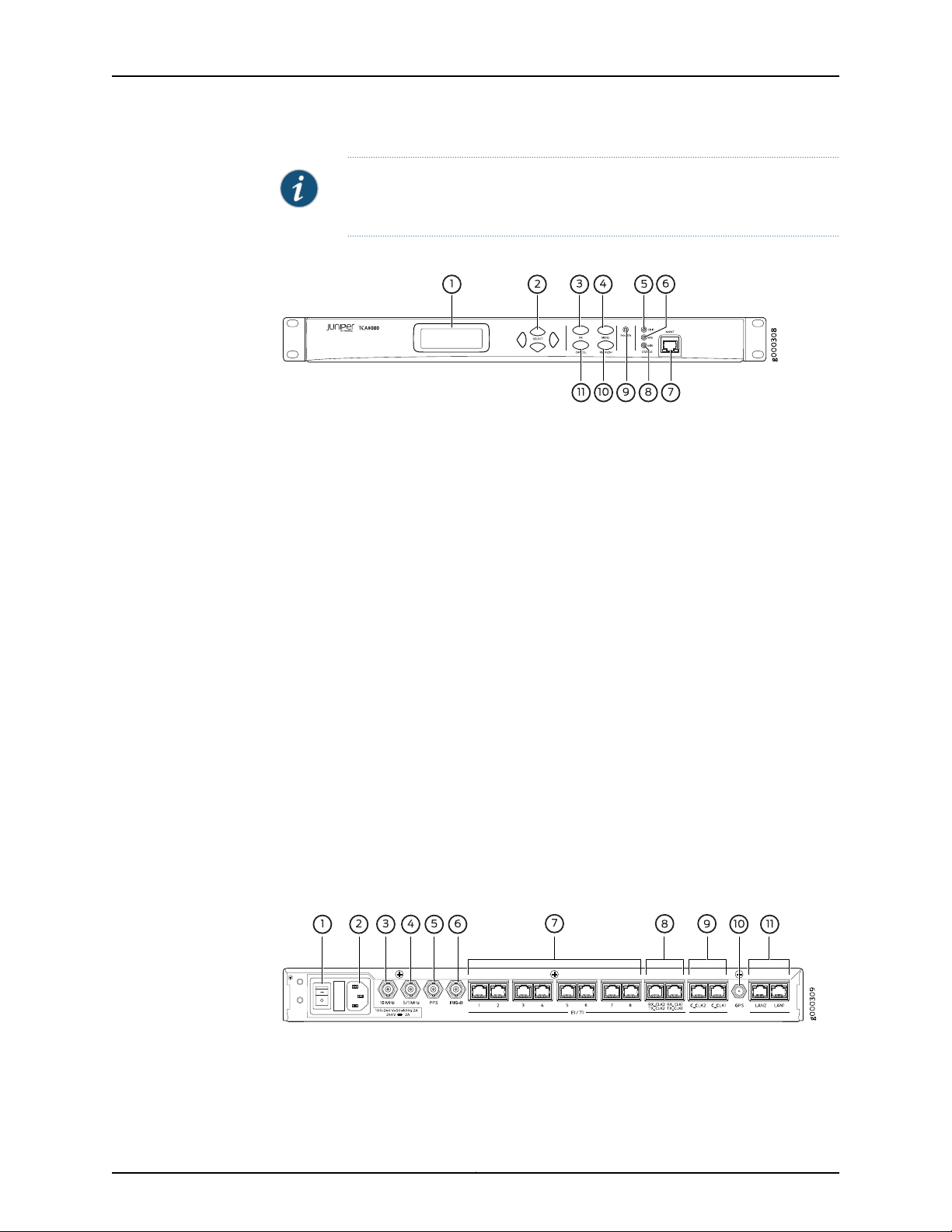
Figure 1: TCA8000 and TCA8500—AC Timing Server, Front View
The front panel of the Timing Server with AC power connector contains the following
components as shown in the Figure 1 on page 4:
•
1–LCD screen
•
2–Selection buttons
•
3–OK button
•
4–MENU button
•
5–Critical alarm LED
•
6–Major alarm LED
•
7–Craft MGMT port
•
8–Minor alarm LED
•
9–Power LED
•
10–REFRESH button
•
11–CANCEL button
The LCD screen displays the applicable menus and the hostname as “Juniper Networks”.
You can change the default IP address of the Timing Server through the craft MGMT port
or by using the buttons. The LEDs display the power status and alarm statusof the Timing
Server.
Figure 2: TCA8000 and TCA8500—AC Timing Server, Rear View
The rear panel of the Timing Server with AC power connector contains the following
components as shown in the Figure 2 on page 4:
Copyright © 2017, Juniper Networks, Inc.4
Page 21

Chapter 1: TCA8000 and TCA8500 Timing Server Description
•
1–Power switch
•
2–AC power connector
•
3–10 MHz timing output port
•
4–5/1 MHz timing output port
•
5–PPS timing output port
•
6–IRIG-B timing output port
•
7–T1/E1 timing output ports (BITS)
•
8–T1/E1 timing input/output ports (BITS)
•
9–CClock timing output ports
•
10–GPS antenna port
•
11–LAN ports
The power switch is used to switch on or switch off the power of the Timing Server. The
AC power connector is used to supply power to the Timing Server. Timing output ports
are used to deliver 5/1 MHz output signal, 10 MHz output signal, Pulse-per-Second(PPS)
output signal, Inter-Range Instrumentation Group – B (IRIG-B) output signal, T1/E1 output
signal, and CClock output signal. Timing input/output ports are used to receive input
from external T1/E1 sources and provide a timing T1/E1 source outputs. The GPS antenna
port is used to connect the Timing Server with an appropriate GPS L1 antenna. Each LAN
port is an RJ45 connector with synch and activity LEDs. Both the LAN ports can be used
for out-of-band management network connectivity that is Telnet, web interface, and
SNMP. The LAN port “LAN1” is used for the PTP or NTP network connectivityto the Timing
Clients.
Figure 3: TCA8000 and TCA8500—DC Timing Server, Front View
The front panel of the Timing Server with DC power connectors contains the following
components as shown in the Figure 3 on page 5:
•
1–Retainer screws
•
2–LCD screen
•
3–Selection buttons
•
4–OK button
•
5–MENU button
•
6–Power LED
5Copyright © 2017, Juniper Networks, Inc.
Page 22
TCA8000 and TCA8500 Timing Server Installation and Configuration Guide
•
7–Critical alarm LED
•
8–Major alarm LED
•
9–ESD grounding point
•
10–Craft MGMT port
•
11–Minor alarm LED
•
12–ACO button
•
13–REFRESH button
•
14–CANCEL button
•
15–Card ejectors
The LCD screen displays the applicable menus and the hostname as “Juniper Networks”.
You can change the default IP address of the Timing Server through the craft MGMT port
or by using the corresponding buttons. The LEDs display the power status and alarm
status of the Timing Server. The retainer screws are used to secure the removable base
board inside the chassis and the card ejectors are used to gently remove the base board
from the chassis for service. You can clear all alarms set on the device by using the ACO
button.
CAUTION: You must loosen the retainer screws before removing the base
board from the chassis using the card ejectors for any servicing requirement.
CAUTION: To protect the device and its components from electrostatic
damage, wear an antistatic wrist strap and connect it to the ESD grounding
point while handling the device.
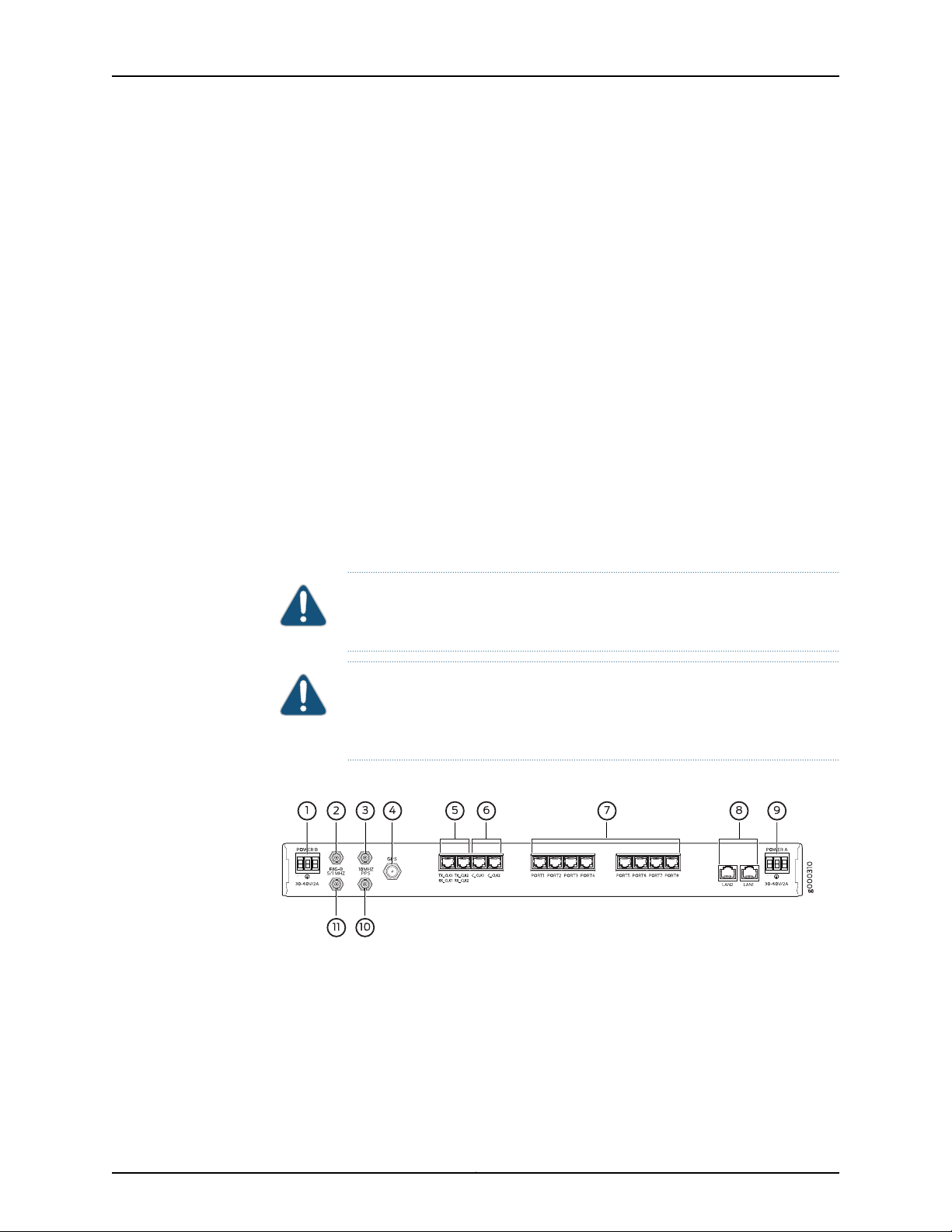
Figure 4: TCA8000 and TCA8500—DC Timing Server, Rear View
The rear panel of the Timing Server with DC power connectors contains the following
components as shown in the Figure 4 on page 6:
•
1–DC power terminal B
•
2–IRIG-B timing output port
•
3–10 MHz timing output port
•
4–GPS antenna port
Copyright © 2017, Juniper Networks, Inc.6
Page 23

Chapter 1: TCA8000 and TCA8500 Timing Server Description
•
5–T1/E1 timing input/output ports (BITS)
•
6–Cclock timing output ports
•
7–T1/E1 timing output ports (BITS)
•
8–LAN ports
•
9–DC power terminal A
•
10–PPS timing output port
•
11–5/1 MHz timing output port
Both of the DC terminals have positive, negative, and ground terminals used to connect
a DC power source to the Timing Server. All other components of the DC version Timing
Server performs the same operation as that of the AC version Timing Server.
7Copyright © 2017, Juniper Networks, Inc.
Page 24

TCA8000 and TCA8500 Timing Server Installation and Configuration Guide
Copyright © 2017, Juniper Networks, Inc.8
Page 25

PART 2
Installing and Setting Up a TCA8000 or
TCA8500 Timing Server
•
Installing and Setting Up a TCA8000 or TCA8500 Timing Server on page 11
9Copyright © 2017, Juniper Networks, Inc.
Page 26

TCA8000 and TCA8500 Timing Server Installation and Configuration Guide
Copyright © 2017, Juniper Networks, Inc.10
Page 27

CHAPTER 2
Installing and Setting Up a TCA8000 or
TCA8500 Timing Server
This chapter describes the procedure to correctly install the Juniper Networks TCA8000
and TCA8500 Timing Server. The following topics are described:
•
Unpacking the TCA8000 or TCA8500 Timing Server on page 11
•
Requirements for Installing a TCA8000 or TCA8500 Timing Server on page 11
•
Reserving an IP Address for the TCA8000 or TCA8500 Timing Server on page 12
•
Installing the TCA8000 or TCA8500 Timing Server on page 12
•
Recommendations for Mounting the Antenna (TCA8000 or TCA8500 Timing
Server) on page 12
•
Changing the Password of Admin User Account on page 14
•
Assigning an IP Address to the TCA8000 or TCA8500 Timing Server on page 16
•
Visually Testing the TCA8000 or TCA8500 Timing Server With GPS on page 17
•
Verifying the Product T1/E1 Interface Support on page 18
Unpacking the TCA8000 or TCA8500 Timing Server
The Timing Server is shipped with the following items to ensure an optimum installation:
•
TCA8000 or TCA8500 Timing Server
Requirements for Installing a TCA8000 or TCA8500 Timing Server
This section describes the requirements to correctly install and use the TCA8000 or
TCA8500 Timing Server. Table 2 on page 12 lists the items needed to install the Timing
Server.
You must use an appropriate GPS L1 antenna (1575.42 MHz) to receive a minimum GPS
signal from the Timing Server. The antenna must allow a minimum signal input level of
20 dB with respect to the antenna output for the Timing Server.
11Copyright © 2017, Juniper Networks, Inc.
Page 28
TCA8000 and TCA8500 Timing Server Installation and Configuration Guide
NOTE: To calculate whether the external antenna, cable type, and length
meets the minimum TCA GPS antenna input, use the following formula:
TCA GPS signal input = antenna gain – [(cable length) * (cable loss / Meter
or Feet)]
Table 2: Antenna Mounting Requirements
Customer Supplied
•
GPS L1 antenna with a frequency band of 1575.42 +/-10 MHz 3 dB bandwidth.
•
Antenna mount
•
Mounting area clear for at least two meters of any metal or other material that could act as a
shield and block the GPS signal
•
160 degree clear view of the sky
•
Clamps, cable ties, and so on, to secure cable
Reserving an IP Address for the TCA8000 or TCA8500 Timing Server
The TCA8000 and TCA8500 Timing Servers support both dynamic and static IP
addressing. If a static address is required, an IP address must be reserved and assigned
for the Timing Server by a network administrator. The DHCP server will always assign a
unique address.
Installing the TCA8000 or TCA8500 Timing Server
Install the Timing Server in a 19-in. or 23-in. rack using the supplied rack mount kit. The
AC system is shipped with the appropriate country power cord and should be connected
to the input plug on the back of the unit. For the DC system the -48 V DC on the back of
unit should be connected to the 48 V DC source.
CAUTION:
For the -48 V DC option:
•
Ground cable—Make a ground cable using 8-gauge wire with the supplied
ground lug. This should attachto your building’s earth ground infrastructure.
•
Power— Route powerconnection using 18-22 gaugewire to a 48-volt circuit
breaker panel.
Recommendations for Mounting the Antenna (TCA8000 or TCA8500 Timing Server)
This section describes mounting the antenna for the Timing Server at a location where
the unit will receive a GPS signal from several satellites. A site survey is highly
recommended prior to any installation activity. This will determine the best method and
location for mounting the antenna. A site survey will also provide additional information
Copyright © 2017, Juniper Networks, Inc.12
Page 29

including cable lengths and required mounting materials in order to perform a secure
and reliable installation.
•
Optimal GPS Antenna Mounting Conditions on page 13
•
Minimal TCA8000 or TCA8500 Timing Server Installation Conditions on page 13
•
Mounting the Antenna on page 13
Optimal GPS Antenna Mounting Conditions
Ideally, the GPS antenna should be mounted where a 160° clear view of the sky (a 10°
angle from horizontal) is available to enable a connection to visible GPS satellites. The
ideal mounting location is a roof, tower or an antenna mast, high above any obstruction
or any device that may cause signal interference. We recommend a location that has the
following characteristics:
•
Clear view of the sky in all directions—at least 270°
•
Away from high-power transmitters and radar antennas
•
At least 3 meters away and at least 1 meter below the highest point of a lightning rod
Chapter 2: Installing and Setting Up a TCA8000 or TCA8500 Timing Server
•
Convenient path for running the outdoor coax cable from the GPS antenna to the
network
Minimal TCA8000 or TCA8500 Timing Server Installation Conditions
The TCA8000 or TCA8500 Timing Server can still maintain accurate time when an
antenna is mounted in a location that has limited visibility of GPS satellites; however, it
is recommended any obstructions should be minimized. Limitations to satellite visibility
for an antenna include overhanging foliage or tall structures. Such structures can block
the GPS signal from the antenna and cause gaps in the GPS satellite signal reception. In
locations where satellite visibility is limited, it is suggested the following be considered:
•
Position the antenna for the Timing Server on the side of the structure with good visibility
toward the equator where more satellites are visible. For example, if you are in the
northern hemisphere, place the unit on the southern side of the structure unless that
view is restricted or blocked. If that view is restricted or blocked, place the unit on the
east or west side of the structure. Avoid the polar side where there are fewer visible
satellites.
•
Ensure that the GMT time zone parameter is set while you configure the Timing Server.
Mounting the Antenna
Follow the manufacturer’s guidelines for the installation of the GPS antenna.
Route the coax cable from the newly installed antenna into the building following the
manufacturer’s antenna safety guidelines.
Route the coax from the building’s ingress to the server’s installation site, and connect
to the GPS server.
13Copyright © 2017, Juniper Networks, Inc.
Page 30

TCA8000 and TCA8500 Timing Server Installation and Configuration Guide
WARNING:
•
Locate the TCA8000 or TCA8500 Timing Server away from power lines,
electric lights, and power circuits.
•
When installing the Timing Server,do not touch powerlines, or other sources
of live power.
•
Have a qualified technician and or certified electrician perform the
installation.
•
Observe all local and regulatory standards and ordinances.
•
Grounding the unit (metal mast or ground cable to the unit’s base) is
required for the lightning protection to work properly.
Changing the Password of Admin User Account
Juniper Networks assigns a default user account (admin/admin) with login class as
Admin to a TCA8000 or TCA8500 Timing Server for logging in to the Timing Server. You
can create and manage Read-Only or Read/Write user accounts in the TCA8000 or
TCA8500 Timing Server by logging in as admin. For more information about TCA user
account management, see “Managing TCA User Accounts” on page 49 and “TCA User
Accounts Overview” on page 21.
BEST PRACTICE: Before installing the Timing Server on an active network,
change the default password (admin) of the Admin user to maintain secure
access to the Timing Server.
NOTE: You can reset passwords of the Admin user and the enable mode to
factory defaults through the CLI, GUI, or hardware mechanism. For more
informationabout resettingof passwords,see “Changing/Resetting the Login
Password for Admin User” on page 28 and “Resetting the Passwords of Both
Admin User Account and Enable Mode to Factory Defaults” on page 165.
To change the password of the Admin user, one of the following methods may be used:
•
Configuration through the craft MGMT port on the front panel:
1. Login as admin.
a. >admin<cr>
b. >password: admin<cr>
2. Enable privileged commands.
a. >enable<cr>
Copyright © 2017, Juniper Networks, Inc.14
Page 31

Chapter 2: Installing and Setting Up a TCA8000 or TCA8500 Timing Server
b. >password: enable<cr>
3. Execute the following command to change the Admin user password:
# config password
Please input old password: admin<cr>
Please input new password: admin123<cr>
Please re-type new password: admin123<cr>
•
Configuration from the management interface through the Ethernet port on the back
panel:
1. Connect a standard Ethernet cable between the Timing Client, LAN1/LAN2, and the
network port of the PC.
2. Launch an Internet browser on your PC.
3. In the URL field, type the following default IP address:
LAN1–http://192.168.0.200
LAN2–http://192.168.1.200
The Timing Server login page appears.
4. In the Login field, enter the following:
admin (Case sensitive—use all “lower” case)
5. In the password field, enter the following:
admin (Case sensitive—use all “lower” case)
6. Click the Login button.
7. Click the Admin tab and locate the Password tab across the top tabs of the Admin
page.
8. In the Hostname field, enter the name assigned to the Timing Server.
9. In the Old Password field, enter the current password of the Admin user.
10. In the New Password field, enter the new password to replace the old password.
11. In the Retype New Password field, reenter the new password.
12. Click the Apply button to save hostname and password changes to the memory.
15Copyright © 2017, Juniper Networks, Inc.
Page 32

TCA8000 and TCA8500 Timing Server Installation and Configuration Guide
NOTE: All the examples in this guide use the default password (admin) for
the Admin user.
Assigning an IP Address to the TCA8000 or TCA8500 Timing Server
Juniper Networks assigns a default IP address to a TCA8000 or TCA8500 Timing Server
to allow access to the user interface. The default IP address must be changed before
installing the Timing Server on an active network. To change the IP address, one of the
following methods may be used:
•
Manual entry from the keypad on the front panel.
•
Configuration through the craft MGMT port on the front panel.
•
Configuration from the management interface through the Ethernet port.
To change the IP address through the Ethernet port:
1. Connect the standard Ethernet cable between the Timing Server,LAN 1/LAN 2 ports
and the network port of the PC.
2. Apply power to the Timing Server.
3. Launch an Internet browser on your PC.
4. In the URL field, type the following default IP address:
LAN1—http://192.168.0.200
LAN2—http://192.168.1.200
The Timing Server login page appears.
5. In the Login field, enter the following:
admin (Case sensitive–use all “lower” case)
6. In the password field, enter the following:
admin (Case sensitive–use all “lower” case)
7. Click the Login button.
8. Click the Config tab if it not already displayed (default).
Copyright © 2017, Juniper Networks, Inc.16
Page 33

Chapter 2: Installing and Setting Up a TCA8000 or TCA8500 Timing Server
9. Select the LAN1 option button.
10. Locate Mode in the Network section, and select the Static or DHCP button that will
be used to assign the Timing Server an IP address, and perform one of the following:
a. Select the Static button and enter the following information in the fields above
the Mode selection:
•
In the IP Addressfield, enter the IP address to be assigned to the Timing Server.
•
In the Mask field, enter the subnet mask to be assigned to the Timing Server.
•
In the Gateway field, enter the IP address of the gateway to be assigned to
the Timing Server.
•
In the Primary DNS field,enter the IP address of the primary DNS to be assigned
to the Timing Server.
NOTE: Leave blank, if not required.
•
In the Secondary DNS field, enter the IP address of the secondary DNS to be
assigned to the Timing Server.
NOTE: Leave blank, if not required.
Apply, save.
b. If the DHCP button is selected, the DHCP server will automatically provide the
Timing Server with IP address information.
Apply, save.
Connect to the network.
c. Contact a network administratorto enable appropriatesettings for the following:
•
Speed (100 Mbps, recommended)
•
Duplex (Full-duplex, recommended)
•
Auto negotiation (Disabled, recommended)
Visually Testing the TCA8000 or TCA8500 Timing Server With GPS
1. Connect the Timing Server and computer to the local network segment and launch
the web browser.
2. Open the Timing Server webpage by using the new IP address (from above), enter
login/password.
17Copyright © 2017, Juniper Networks, Inc.
Page 34

TCA8000 and TCA8500 Timing Server Installation and Configuration Guide
3. Click the Status button and observe the System page. The following information
should be present:
•
Model
•
Board S/N
•
System S/N
•
Software version
•
Hardware version
•
FPGA version
•
Temperature
•
MAC addresses for LAN 1 and LAN 2 ports
4. Click the GPS page, and observe the following information:
•
Receiver status = Good
•
Antenna status = Good
•
Satellite status = Acquired
Verifying the Product T1/E1 Interface Support
The TCA8000 or TCA8500 Timing Server ship with both T1 and E1 software images
installed in the two internal non-volatile memory partitions. By default, the TCA8000 or
TCA8500 Timing Server use the E1 interface type. To select the T1 interface type, see
“Upgrading the TCA8000 and TCA8500 Software” on page 67.
Copyright © 2017, Juniper Networks, Inc.18
Page 35

PART 3
Configuring and Upgrading the TCA8000
or TCA8500 Timing Server
•
Configuring a TCA8000 or TCA8500 Timing Server on page 21
•
Upgrading the TCA8000 and TCA8500 Software on page 67
19Copyright © 2017, Juniper Networks, Inc.
Page 36

TCA8000 and TCA8500 Timing Server Installation and Configuration Guide
Copyright © 2017, Juniper Networks, Inc.20
Page 37

CHAPTER 3
Configuring a TCA8000 or TCA8500
Timing Server
This chapter describes the procedure to configure the Juniper Networks TCA8000 and
TCA8500 Timing Servers. The following topics are described in this chapter:
•
TCA User Accounts Overview on page 21
•
Dynamic SSL Certificate Overview on page 23
•
Accessing the User Interface on page 23
•
Requirements for Using the Graphical User Interface on page 24
•
Accessing the Graphical User Interface on page 24
•
Changing/Resetting the Login Password for Admin User on page 28
•
Changing the IP Address on page 30
•
Setting Precision Time Protocol (PTP) Parameters on page 33
•
Setting NTP Parameters on page 37
•
Configuring Alarms on page 42
•
Configuring Traps on page 44
•
Managing TCA User Accounts on page 49
•
Changing the Login Password for Read/Write User on page 51
•
Configuring User Authentication through RADIUS on page 53
•
Configuring RADIUS Accounting on page 57
•
Specifying Recipients for Alarm E-Mail Notifications on page 60
•
Resetting Factory Defaults on page 63
•
Stopping and Restarting the TCA8000 or TCA8500 Timing Server on page 64
TCA User Accounts Overview
Juniper Networks assigns a default user account (admin/admin) with login class as
Admin to a TCA8000 or TCA8500 Timing Server for logging in to the Timing Server. The
user logging in to the Timing Server using the Admin user account can configure the
Timing Server and create, delete or modify user accounts with login class as Read-Only
or Read/Write.
21Copyright © 2017, Juniper Networks, Inc.
Page 38

TCA8000 and TCA8500 Timing Server Installation and Configuration Guide
The TCA software supports three predefined login classes to define the access privileges
for the user accounts in your Timing Server. Table 3 on page 22 defines the login classes
predefined in the TCA software.
Table 3: Login Classes for TCA User Accounts
DescriptionAccess PrivilegeLogin Class
Admin
Create, Delete, or
Modify
ModifyRead/Write
Show viewRead-Only
User can:
•
Configure all Timing Server features or parameters through CLI or WEB.
•
View all Timing Server configuration or log details through CLI or WEB.
User can:
•
Configure Timing Server features or parameters through CLI or WEB except
Admin user functionalities such as creation, deletion, and modifying of user
accounts.
•
View Timing Server configurationor log details through CLI or WEB exceptsome
of the Admin user functionalities such as viewing command history of other
user accounts.
User can:
•
View Timing Server configurationor log details through CLI or WEB exceptsome
of the Admin user functionalities such as viewing command history of other
user accounts.
The TCA software creates a separate log file for each user account to store the commands
executed by the corresponding user. The software stores the session ID and timestamp
in the log file to identify the various sessions for that particular user.The software deletes
the log file created for the user account, when the Admin user deletes any Read-Only or
Read/Write user account.
NOTE: The software can store only a maximum of 150 commands in a log
file.
Guidelines for User Account Management
Keep in mind the following considerations when you (Admin) configure user accounts:
•
The software supports only five user accounts.
•
You cannot delete the default Admin user account assigned by Juniper Networks.
•
You cannot create another Admin user account.
•
The username should be 4 to 12 characters long. The characters can only include
alphanumeric and underscore. No other special characters are allowed.
•
The username should be unique.
•
The password should be 4 to 12 characters long. The characters can include
alphanumeric and special characters (that is, !@#$_).
Copyright © 2017, Juniper Networks, Inc.22
Page 39

Dynamic SSL Certificate Overview
The TCA 8000 or 8500 Timing Server enables you to access the GUI through Hypertext
Transfer Protocol (HTTP) or Hypertext Transfer Protocol over Secure Sockets Layer
(HTTPS) based on the web mode configured by the Admin user. The Admin user can
configure the Timing Server to use the customized key and certificate instead of the
default key and certificate, when the GUI is accessed through HTTPS. By default, the
Timing Server uses the default key and certificate when the GUI is accessed through
HTTPS.
The Admin user can download the customized key and certificate files of .pem format
in the Timing Server through CLI or GUI. The downloaded key file is stored as an
ssl_key.pem file in the etc/config path. The downloaded certificate file is stored as an
ssl_cert.pem file in the etc/config path. The Admin user can generate the customized
files by using OpenSSL or FIPS 140-2 capable OpenSSL as trusted certification authority.
For complete information and source of OpenSSL utility, see http://www.openssl.org/.
When you access the GUI through HTTPS, the Timing Server checks for the ssl_key.pem
and ssl_cert.pem files in the etc/config path. If any one of the files is not available, the
Timing Server uses the default key and certificate. If the files are available, the Timing
Server checks the BEGIN header and the END footer in both the files. If the header and
footer are valid in both the files, the Timing Server compares the key file with the certificate
file. On successful match, the Timing Server loads the GUI and generates a syslog.
Chapter 3: Configuring a TCA8000 or TCA8500 Timing Server
The Timing Server does not load the GUI but generates a syslog during the following
scenarios:
•
Mismatch identified between the key and certificate files.
•
Invalid header or footer identified in one of the files.
•
Validity of any file got expired.
The Admin user must keep the following conditions in mind when uploading the
customized files:
•
After uploading both the files, you must reboot the Timing Server for the changes to
take effect.
•
The Timing Server uses the default key and certificate if both or any one of the
customized files is unavailable.
•
You cannot modify the downloaded files but you can replace them with another ones.
•
You should use only Secure HashAlgorithm (SHA-1) and RSA (1024 bits) cryptographic
algorithms while generating the customized key and certificate files.
Accessing the User Interface
You can configure the TCA8000 or TCA8500 Timing Server using one of the following
methods:
23Copyright © 2017, Juniper Networks, Inc.
Page 40

TCA8000 and TCA8500 Timing Server Installation and Configuration Guide
•
Graphical user interface (GUI)
•
Telnet
•
Secured shell (SSH)
This chapter describes how to access the GUI. Accessing the Timing Server using Telnet
and SSH is described in
“Using Telnet with the TCA8000 and TCA8500 Timing Servers” on page 163.
Requirements for Using the Graphical User Interface
To use the TCA8000 or TCA8500 GUI, log in to the embedded Web server with an
Internet browser. The following browsers and versions are supported:
•
Internet Explorer version 11.x or later
•
Firefox version 1.5.0.7 or later (Firefox 3.0 is currently not supported)
The Web GUI is optimized to work and appear better in a 1280*1024 display resolution.
Accessing the Graphical User Interface
To access the GUI:
1. Open an Internet browser.
2. In the address or URL field enter the IP address assigned to the Timing Server to be
accessed, using the following command:
http://ip_address
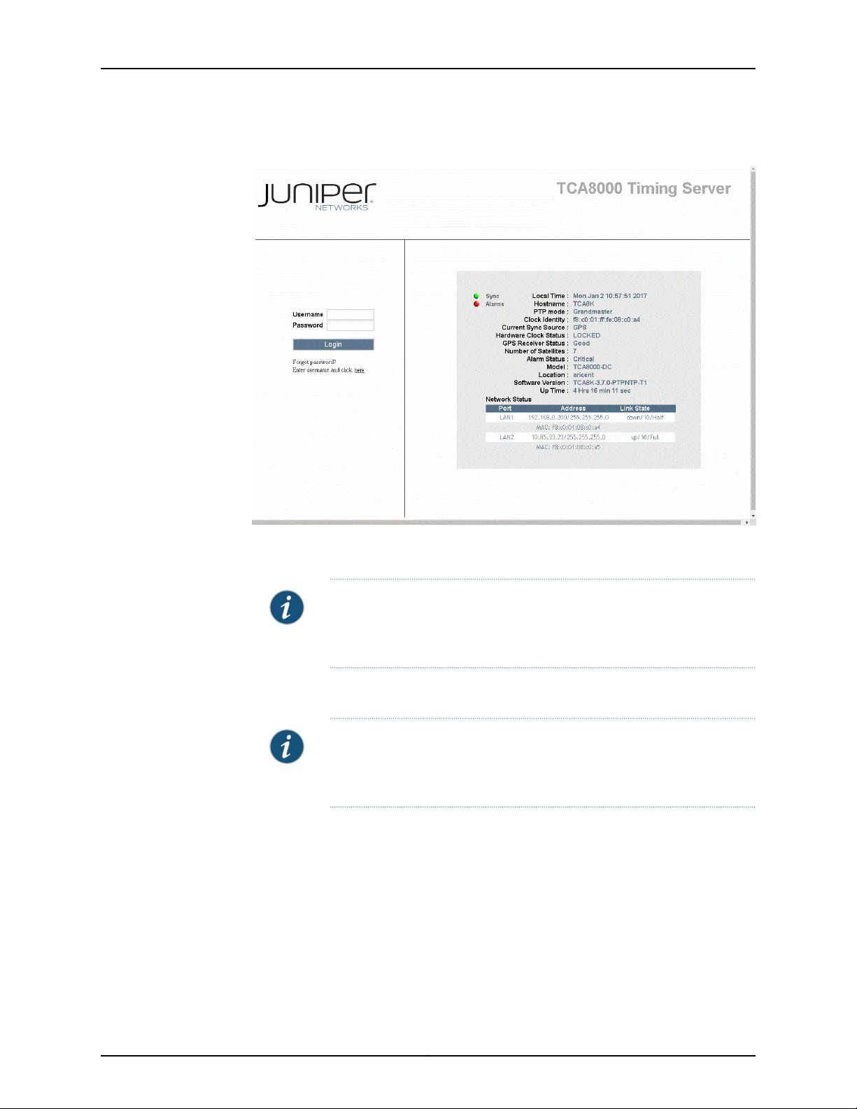
The Login page appears. See Figure 5 on page 25.
Copyright © 2017, Juniper Networks, Inc.24
Page 41
Chapter 3: Configuring a TCA8000 or TCA8500 Timing Server
Figure 5: TCA8000 or TCA8500 Timing Server Login Page
3. In the Username field enter the username that you want to use to log in to the server.
NOTE: The default username assigned by the Juniper Networks is admin.
You cannot change the default username. You can create new user
accounts from the config page by logging in as Admin user.
4. In the Password field enter the password required to log in to the server.
NOTE: The default password assigned by the Juniper Networks is admin.
You can change the log in password of the Admin user from the Admin
page.
5. Click the Login button. The Status page appears. See Figure 6 on page 26.
25Copyright © 2017, Juniper Networks, Inc.
Page 42

TCA8000 and TCA8500 Timing Server Installation and Configuration Guide
Figure 6: Timing Server Status Page—System Pane
The Timing Server GUI will automatically time out after the timeout period configured
using the config web-timeout command. The login and password will have to be
reentered to gain access to the unit.
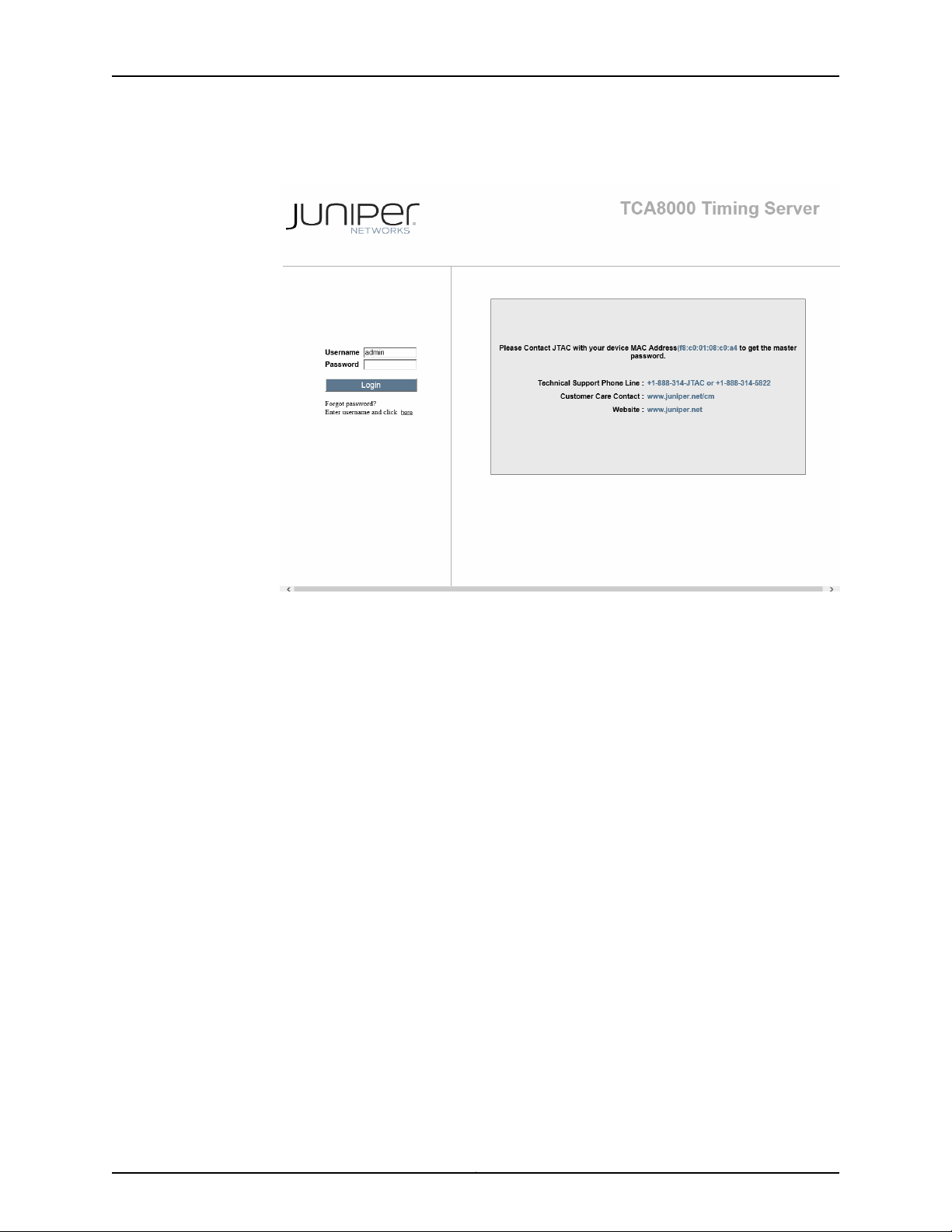
6. If you have forgottenthe password, enter the username and click the Forgot Password
link.
For Admin user accounts, you will be prompted to contact JTAC with the MAC address
to get the master password. See Figure 7 on page 27.
Copyright © 2017, Juniper Networks, Inc.26
Page 43
Chapter 3: Configuring a TCA8000 or TCA8500 Timing Server
Figure 7: Admin Users—Resetting the Forgotten Password
Upon logging in with the master password, the Admin user has to set a new password.
For non-admin user accounts, you will be prompted to enter the username and e-mail
ID. Upon successful authentication, you will get the new password in your e-mail. See
Figure 8 on page 28.
27Copyright © 2017, Juniper Networks, Inc.
Page 44

TCA8000 and TCA8500 Timing Server Installation and Configuration Guide
Figure 8: Non-Admin Users—Resetting the Forgotten Password
Changing/Resetting the Login Password for Admin User
We recommend that the TCA8000 or TCA8500 Timing Server login password of the
Admin user be changed from the manufacturer set default to maintain secure access to
the server.
Copyright © 2017, Juniper Networks, Inc.28
Page 45

Chapter 3: Configuring a TCA8000 or TCA8500 Timing Server
To change the login password of the Admin user:
1. Click the Admin tab.
The Admin page—Password pane appears. See Figure 9 on page 29.
NOTE: The Admin tab is visible only to the Admin user.
Figure 9: Timing Server Admin Page—Password Pane
2. In the Hostname field of the System Name & Password section, enter the hostname
to be assigned to the Timing Server.
3. In the Old Password field, enter the current admin password.
4. In the New Password field, enter the password that you want to use.
NOTE: Passwords are casesensitive and accept alphanumeric characters.
Passwords must contain a minimum of four characters.
5. In the Retype New Password field, enter the password that you want to use.
6. Click the Apply button.
29Copyright © 2017, Juniper Networks, Inc.
Page 46

TCA8000 and TCA8500 Timing Server Installation and Configuration Guide
To reset passwords of the Admin user and the enable mode to factory defaults:
1. Click the Admin tab.
The Admin page—Password pane appears. See Figure 9 on page 29.
NOTE: The Admin tab is visible only to the Admin user.
2. Select the Default Password check box.
3. Click the Apply button to reset passwords of the Admin user and the enable mode to
factory defaults.
NOTE: If you have forgotten the password of the Admin user, you can
reset the password to factory default through hardware mechanism. For
more information about resetting the password through hardware
mechanism, see “Resetting the Passwords of Both Admin User Account
and Enable Mode to Factory Defaults” on page 165.
Changing the IP Address
The TCA8000 and TCA8500 Timing Servers are configured to use the manufacturer’s
default static IP addresses assigned to the Ethernet ports. Use the user interface to
manually change the IP addresses of the Ethernet ports and configure or change VLAN
settings for the Ethernet ports.
To change the address information for Ethernet ports:
1. Click the Config tab. The Config page appears. See Figure 10 on page 32.
2. In the Mode field, click the Static button to activate the address fields.
3. In the IP Address field, enter the IP address that you want the Timing Server to use.
NOTE: You cannot configure Ethernet and VLAN port addresses to be in the
same subnet (that is, all logical and physical interfaces should be configured
to be in different subnets).
NOTE: After you save the IP address change, you must launch the Timing
Server user interface using the new IP address to view and configure the
current settings.
Copyright © 2017, Juniper Networks, Inc.30
Page 47

Chapter 3: Configuring a TCA8000 or TCA8500 Timing Server
4. In the Mask field, enter the subnet mask that you want the Timing Server to use.
5. In the Gateway field, enter the IP address of the gateway with which you want the
Timing Server to register.
6. In the Primary DNS field, enter the IP address of the Primary DNS with which you want
to register the Timing Server.
7. In the Secondary DNS field, enter the IP address of the Secondary DNS with which
you want to register the Timing Server.
8. To determine whether an IP address is currently assigned, enter the IP address in the
Ping field and click Go. If the ping goes through, then the IP address is already taken.
Otherwise, it is not assigned, and can be used by the Timing Server.
9. Click the Apply button to save and implement the changes.
To configure or change VLAN settings for the Ethernet ports:
1. Click the Config tab. The Config page appears. See Figure 10 on page 32.
2. In the LAN field,select a LAN (LAN1 or LAN2) for which VLAN settings to be configured.
3. In the Mode field, select the Static option button to activate the VLAN address fields.
4. In the Static Route field, select an option button to add a static route that defines a
gateway IP address for reaching the destination network or delete the static route.
5. In the VLAN field, select a VLAN (VLAN1 or VLAN2) for which settings should be
configured.
6. In the IP Address field, enter the IP address for the selected VLAN.
7. In the Mask field, enter the subnet mask assigned to the selected VLAN.
8. In the Id field, enter a unique identifier in the range 2 through 4095 that is used to
identify the VLAN encapsulation packet.
NOTE: If the ID you have entered is already being used by any other VLAN,
a warning message is displayed.
9. In the Priority field, enter a priority value for the VLAN header to be used for differential
services transporting the packet.
31Copyright © 2017, Juniper Networks, Inc.
Page 48
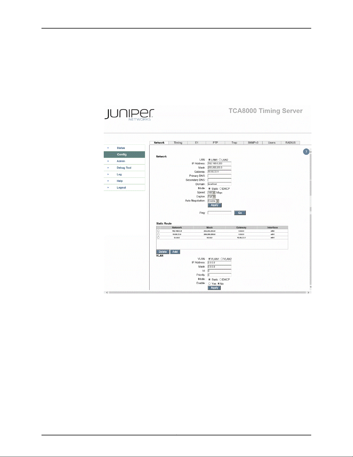
TCA8000 and TCA8500 Timing Server Installation and Configuration Guide
10. In the Enable field, select the Yes option button to enable VLAN encapsulation for IP
packets, or select the No option button to disable VLAN encapsulation for IP packets.
11. Click Apply to save and implement the changes.
Figure 10: Timing Server Config Page—Network Pane
Copyright © 2017, Juniper Networks, Inc.32
Page 49

Chapter 3: Configuring a TCA8000 or TCA8500 Timing Server
Setting Precision Time Protocol (PTP) Parameters
Figure 11: Timing Server Config Page—PTP Pane
NOTE: You can view this pane only if the PTP support is enabled in the Timing
Server.
The PTP pane on the Configuration page allows you to set parameters to be part of a
distributed synchronous network using Precision Time Protocol (PTP). To configure the
TCA8000 or TCA8500 Timing Server to provide time synchronization:
1. Click the Config tab. The Config page appears.
2. Locate the PTP tab across the top of the Config page. See Figure 11 on page 33.
3. In the Profile field, select “Default” profile to use multicast PTP messages only, or
“Juniper Type 1” profile to use multicast PTP messages for Announce and Sync, and
unicast messages for Delay Request and Delay Response.
33Copyright © 2017, Juniper Networks, Inc.
Page 50

TCA8000 and TCA8500 Timing Server Installation and Configuration Guide
When you select Telecom Profile, you will get the option to configure Unicast
parameters. See Figure 12 on page 35. The unicast parameters include the following:
•
Delay Range—Range for delay request or response event message rate. Options
are:
•
1 packet/64sec
•
1 packet/32sec
•
1 packet/16sec
•
1 packet/8sec
•
1 packet/4sec
•
1 packet/2sec
•
1 packet/sec
•
2 packet/sec
•
4 packet/sec
•
8 packet/sec
•
16 packet/sec
•
32 packet/sec
•
64 packet/sec
•
128 packet/sec
•
Announce Range—Range for announce interval message rate. Options are:
•
1 packet/1sec
•
1 packet/2sec
•
1 packet/4sec
•
1 packet/8sec
•
2 packet/1sec
•
4 packet/1sec
•
8 packet/1sec
•
Sync Interval— Range for sync event message rate. Options are:
•
1 packet/sec
•
2 packet/sec
•
4 packet/sec
•
8 packet/sec
•
16 packet/sec
Copyright © 2017, Juniper Networks, Inc.34
Page 51

Chapter 3: Configuring a TCA8000 or TCA8500 Timing Server
•
32 packet/sec
•
64 packet/sec
•
Unicast Continuous—Enable or disable unicast continuos option.
Figure 12: Timing Server Config Page—PTP Pane—Telecom Profile
4. In the Priority 1 and Priority 2 fields, enter a value within the range of 0 through 254
to configure the priorities of each master for proper Best MasterClock (BMC) algorithm
operation.
5. The Domain Number field specifies the domain number which the TCA8000 or
TCA8500 Timing Server has been assigned to. Enter a value within the range of 0
through 254 to configure the PTP domain for the Timing Server, which then becomes
a synchronization reference source to all the slave clocks within the same domain
using the PTP protocol.
35Copyright © 2017, Juniper Networks, Inc.
Page 52

TCA8000 and TCA8500 Timing Server Installation and Configuration Guide
6. In the Two Step field, select “no” to enable One-Step clock, or select “yes” to enable
Two-Step clock.
7. In the Log Mean Delay Req Interval field, select a minimum mean time interval at
which you want the Timing Server to respond to successive Delay Request packets
from a slave clock. The default value is 8 pps.
8. In the Log Mean Announce Interval field, select a mean time interval between
successive Announce messages. The default value is 1 pps.
9. In the Log Mean Sync Interval field, select a mean time interval between successive
Sync messages. The default value is 32 pps.
10. Announce Receipt Timeout. The default value is 3.
11. In the DSCP field, enter the Differential Service (DiffServ) value for the IP packet.
12. In the Telecom Standard field, select a telecom standard to be implemented with
the telecom profile for advertising the announce message. The default value is
Telecom-IEEE1588.
13. In the Announce Start Timeout field, enter a value within the range of 0 through 120
minutes. On rebooting, the TCA Timing Server delays the transmission of announce
messageseither until any configured synchronizationsource is locked to the frequency
within the configured timeout value or until the expiry of the configured timeout value.
14. Click the Apply button to save the PTP parameter changes.
When you select Telecom Profile, you will get the option to configure unicast related
parameters. See Figure 12 on page 35. To configure the unicast related parameters:
1. From the Delay Range lists, select the range (minimum and maximum) of delay
request or response event message rate from the options: 1 packet/64sec, 1
packet/32sec, 1 packet/16sec, 1 packet/8sec, 1 packet/4sec, 1 packet/2sec, 1
packet/sec, 2 packets/sec, 4 packets/sec, 8 packets/sec, 16 packets/sec, 32
packets/sec, 64 packets/sec, and 128 packets/sec.
2. From the Announce Range lists, select the range (minimum and maximum) of
announce interval message rate from the options: 1 packet/1sec, 1 packet/2sec, 1
packet/4sec, 1 packet/8sec, 2 packet/1sec, 4 packet/1sec, and 8 packet/1sec.
3. From the Sync Interval lists, select the range (minimum and maximum) of sync event
message rate from the options: 1 packet/sec, 2 packet/sec, 4 packet/sec, 8
packet/sec, 16 packet/sec, 32 packet/sec, and 64 packet/sec.
Copyright © 2017, Juniper Networks, Inc.36
Page 53

Chapter 3: Configuring a TCA8000 or TCA8500 Timing Server
4. From the Unicast Continuous lists, enable or disable unicast continuos option.
5. Click the Apply button to save the unicast parameter changes.
To add the Timing Clients (Slaves) for the Timing Server:
1. In the IP Address field,enter the IP address of the Timing Client (Slave) through which
the Grandmaster sends or receives event messages.
2. Click the Add button to add the Timing Client entry in the Slave List window.
To delete the Timing Client entry:
1. Select the Timing Client entry that you want to delete from the Slave List window.
2. Click the Delete button to delete the entry or click the Clear All button to delete all
the entries from the Slave List window.
Setting NTP Parameters
The TCA8000 and TCA8500 Timing Servers support using the NTP to synchronize time.
You can define the NTP association details and the MD5 key list to configure NTP.
•
Enabling the NTP Support on page 37
•
Creating an NTP Association Entry on page 38
•
Modifying an Existing NTP Association Entry on page 40
•
Adding an NTP Association Entry on page 40
•
Deleting an Existing NTP Association Entry on page 41
•
Configuring the MD5 Key List on page 41
Enabling the NTP Support
The Config pane on the Admin page enables you to configure the protocol (NTP or PTP)
to be used for time synchronization. By default, the PTP support is enabled in the Timing
Server.
To enable the NTP support in the Timing Server:
1. Log in to the Timing Server as Admin user.
2. Click the Admin tab.
3. Locate the Config tab across the top tabs of the Admin page.See Figure 13 on page 38.
37Copyright © 2017, Juniper Networks, Inc.
Page 54

TCA8000 and TCA8500 Timing Server Installation and Configuration Guide
Figure 13: Timing Server Admin Page—Config Pane
4. In the PTP/NTP Config field, select the NTP option button.
5. Click the Apply button.
A dialog box stating “System reboot is required to make changes effective. Do you
want to reboot?” is displayed.
6. Click Yes to reboot the Timing Server with the NTP support.
NOTE:
•
•
Creating an NTP Association Entry
To create a new NTP association entry:
If you reject the rebooting of the Timing Server, the protocol change is
not saved and the Timing Server continues to use the PTP.
After rebooting, you cannot use the PTP commands and panes for
configuring PTP functionalities. To configure PTP functionalities by
using the PTP panes and CLI commands, you must enable the PTP
support and reboot the Timing Server.
Copyright © 2017, Juniper Networks, Inc.38
Page 55
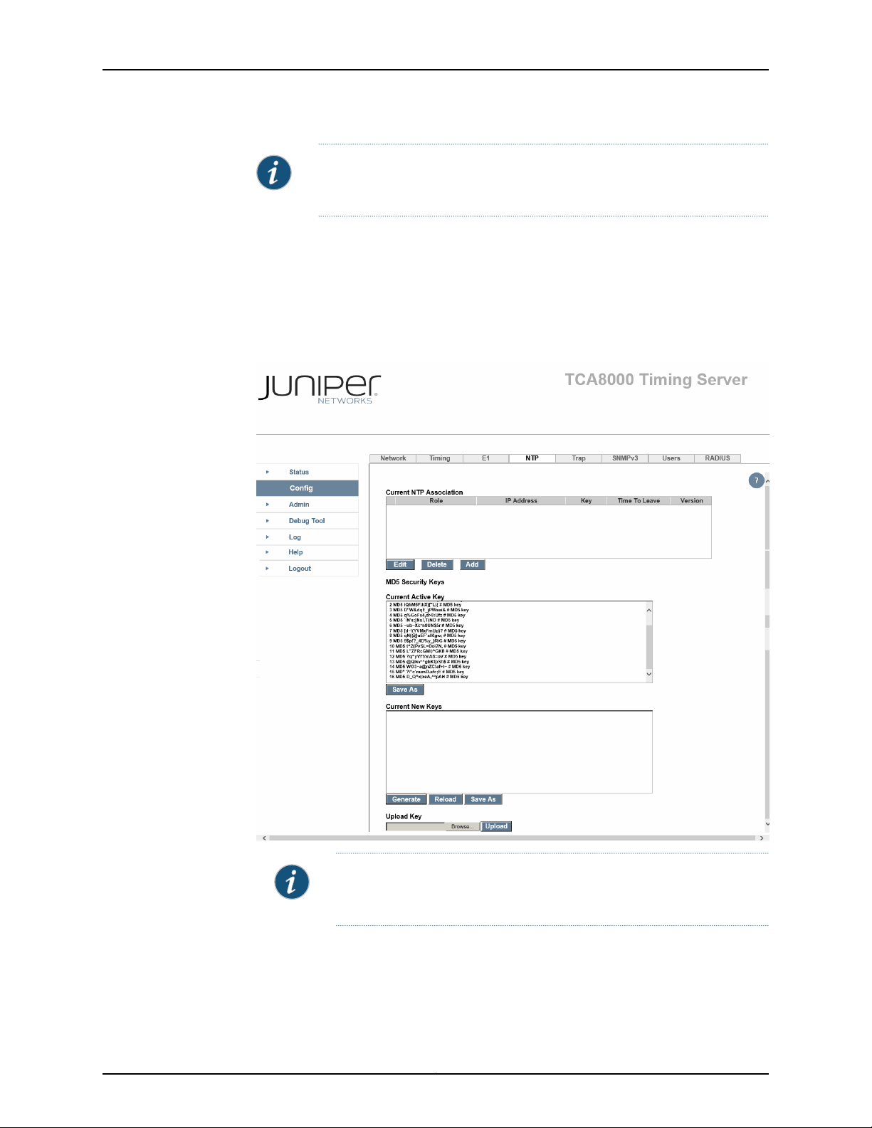
Chapter 3: Configuring a TCA8000 or TCA8500 Timing Server
NOTE: You can add only a maximum of 20 NTP association entries. Each
NTP association entry should have a unique IPv4 address configured.
1. Log in to the Timing Server as Admin or Read/Write user.
2. Click the Config tab.
3. Locate the NTP tab across the top tabs of the Config page. See Figure 14 on page 39.
Figure 14: Timing Server Config Page—NTP Pane
NOTE: You can view this pane only if the NTP support is enabled in the
Timing Server.
4. From the Mode list, select the NTP operation mode for the association entry.
39Copyright © 2017, Juniper Networks, Inc.
Page 56

TCA8000 and TCA8500 Timing Server Installation and Configuration Guide
5. In the Address field,enter the IPv4 address for the associationentry. The IPv4 address
depends on the value selected from the Mode list.
Valid IPv4 AddressMode
Class D or broadcast address of a local interface.Broadcast
Class DManycast Server
6. From the Version list, select the version to be used for the outgoing NTP packets. This
list appears dimmed if you have selected the Manycast Server mode.
7. From the Key list, select the key identifier used for encryption.
8. In the Time to live field, enter the number of hops for the NTP packets. This field
appears dimmed if you have selected the Manycast Server mode.
9. Click the Save button to create a new NTP association entry.
Modifying an Existing NTP Association Entry
To modify an existing NTP association entry:
1. Log in to the Timing Server as Admin or Read/Write user.
2. Click the Config tab.
3. Locate the NTP tab across the top tabs of the Config page. See Figure 14 on page 39.
4. In the Current NTP Association window, select the association entry to be modified.
5. Click the Edit button to modify an existing entry.
6. Modify the applicable parameters for the selected association entry.
7. Click the Save button to save the changes.
Adding an NTP Association Entry
To add a new NTP association entry:
1. Log in to the Timing Server as Admin or Read/Write user.
2. Click the Config tab.
Copyright © 2017, Juniper Networks, Inc.40
Page 57

3. Locate the NTP tab across the top tabs of the Config page. See Figure 14 on page 39.
4. Click the Add button to add a new NTP association entry.
5. Click the Save button to save the changes.
Deleting an Existing NTP Association Entry
To delete an existing NTP association entry:
1. Log in to the Timing Server as Admin or Read/Write user.
2. Click the Config tab.
3. Locate the NTP tab across the top tabs of the Config page. See Figure 14 on page 39.
4. In the Current NTP Association window, select the association entry to be deleted.
Chapter 3: Configuring a TCA8000 or TCA8500 Timing Server
5. Click the Delete button to delete the selected association entry.
Configuring the MD5 Key List
To configure the MD5 key list:
1. Log in to the Timing Server as Admin or Read/Write user.
2. Click the Config tab.
3. Locate the NTP tab across the top tabs of the Config page. See Figure 14 on page 39..
4. Configure the MD key list:
•
Click the Generate button to generate MD5 key list by using the system command
ntp-keygen.
or
•
Click the Browse button to locate a file containing new MD5 keys and click the
Upload button to upload the new keys.
NOTE: You can view this pane only if the NTP support is enabled in the
Timing Server.
41Copyright © 2017, Juniper Networks, Inc.
Page 58

TCA8000 and TCA8500 Timing Server Installation and Configuration Guide
Configuring Alarms
You can specify how you want the TCA8000 or TCA8500 Timing Serverto handle alarms
that occur during operation. To configure the alarms:
1. Click the Admin tab. The Admin page appears.
2. Click the Alarm Profile tab. See Figure 15 on page 43 and Figure 16 on page 44.
3. For each alarm, the following parameters can be configured:
a. Select the Clear Now check box to clear the alarm right away.
b. Select the Auto Clear check box to clear the alarm after it happens for 24 hours.
c. In the Severity field, select the flag to accompany this alarm. Select:
•
Critical—Indicates this alarm needs immediate attention, and is affecting the
normal operation of the Timing Server.
•
Major—Indicates this alarm needs immediate attention.
•
Minor—Indicates this alarm needs attention but is not urgent.
•
None—Indicates this alarm is for information only.
d. Select the Send Trap check box. The Timing Server will send the alarm to the Trap
destinations identified on the Config page.
e. Select the Write Log check box. The Timing Server will send the alarm to the local
log file.
f. Selectthe Send to Email check box. The Timing Serverwill send an e-mail message
about this alarm to the users identified in the Alarm E-mail Recipients section of
the Alarm tab.
Copyright © 2017, Juniper Networks, Inc.42
Page 59
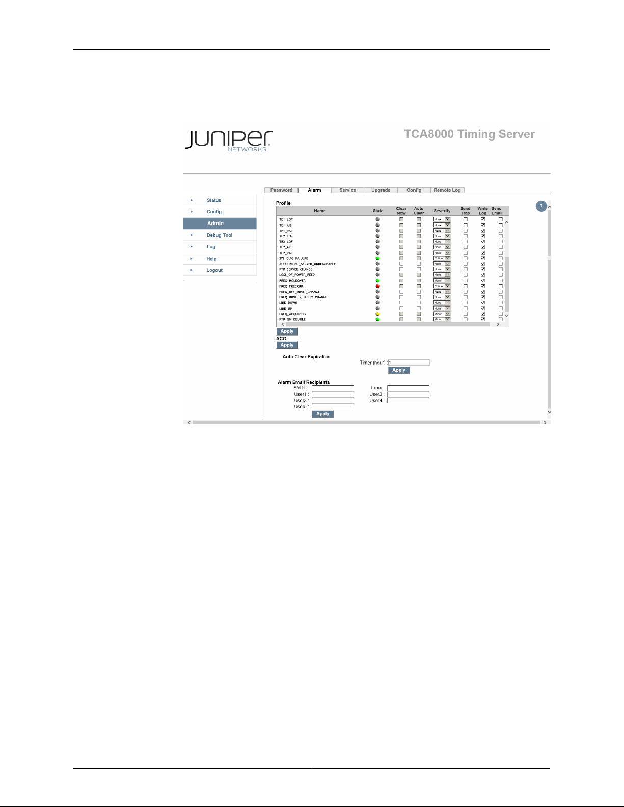
Chapter 3: Configuring a TCA8000 or TCA8500 Timing Server
Figure 15: Timing Server Admin Page—Alarm Pane (PTP)
43Copyright © 2017, Juniper Networks, Inc.
Page 60

TCA8000 and TCA8500 Timing Server Installation and Configuration Guide
Figure 16: Timing Server Admin Page—Alarm Pane (NTP)
Configuring Traps
The TCA8000and TCA8500 Timing Serverscan be configuredtosend event information
to trap destinations on a network.
•
Specifying SNMPv3 Contacts on page 45
•
Creating Trap Targets on page 46
•
Editing Trap Targets on page 46
•
Deleting Trap Targets on page 46
•
Creating SNMPv3 Users on page 47
•
Editing SNMPv3 Users on page 48
•
Deleting SNMPv3 Users on page 48
Copyright © 2017, Juniper Networks, Inc.44
Page 61

Specifying SNMPv3 Contacts
You can configure the TCA8000 or TCA8500 Timing Server to send alarm information
to SNMP community files. To configure the Timing Server to send information to
community files:
1. Click the Config tab. The Config page appears.
2. Locate the Trap tab at the top right of the page. See Figure 17 on page 45.
3. In the sysLocation field, enter the location of the Timing Server.
4. In the sysName field, enter the name used to identify the Timing Server.
5. In the sysContact field, enter the X-address of the manager that you want the Timing
Server to use.
Chapter 3: Configuring a TCA8000 or TCA8500 Timing Server
6. In the ReadOnlyComm field, enter the string that you want the Timing Server to use
to access the local SNMP read community.
7. In the RWriteComm field, enter the string that you want the Timing Server to use to
access the local SNMP write community.
8. Click Apply to save changes.
Figure 17: Timing Server Config Page—Trap Pane
45Copyright © 2017, Juniper Networks, Inc.
Page 62

TCA8000 and TCA8500 Timing Server Installation and Configuration Guide
Creating Trap Targets
To create a Trap destination (see Figure 17 on page 45):
1. Click the Config tab.
2. Locate the Trap tab across the top of the Config page.
3. Click the Add button.
4. In the Address field, enter the IP address where the Timing Server sends event
information.
5. In the Port field, enter the port number through which the Timing Server sends event
information. The default port number is 161.
6. Click the Save button to save your changes.
Editing Trap Targets
Deleting Trap Targets
To edit a Trap destination:
1. Click the Config tab.
2. Locate the Trap tab across the top tabs of the Config screen.
3. Click the Trap address entry to be modified.
4. Click the Edit button to make any changes to the entry from the Trap window and
from memory.
5. Click the Save button to save changes.
To delete a Trap destination:
1. Click the Config tab.
2. Locate the Trap tab across the top tabs of the Config page.
3. Click the Trap address that you want deleted.
4. Click the Delete button to remove the entry from the Trap pane.
Copyright © 2017, Juniper Networks, Inc.46
Page 63

Creating SNMPv3 Users
The TCA8000 and TCA8500 Timing Servers support security measures in SNMPv3. To
create SNMPv3 users:
1. Click the Config tab. The Config page appears.
2. Click the SNMPv3 section across the top of the Config page.See Figure 18 on page 48.
3. Click the Add button.
4. In the Name field, enter the username that will be used to log into SNMPv3 log files.
5. In the Auth Phrase field, enter the authentication phrase you want this user to use.
6. In the Auth Crypt area, select the encryption method that you want this user to use.
Chapter 3: Configuring a TCA8000 or TCA8500 Timing Server
7. In the Pri Phrasefield, enter the privatephrase that you want this user to use if required.
8. In the Pri Protocol field, select the privilege level that you want this user to use. Select:
•
DES—The user must use the authentication phrase to log in.
•
AES—The user is not required to use the authentication phrase to log in.
•
No Privacy—The user is required to use the authentication phrase and the private
phrase to log in.
9. Click the Save button to save the user information in the V3User window.
47Copyright © 2017, Juniper Networks, Inc.
Page 64
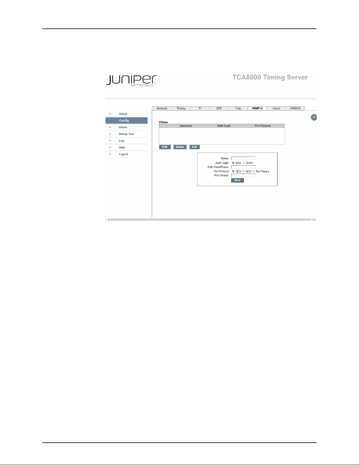
TCA8000 and TCA8500 Timing Server Installation and Configuration Guide
Figure 18: Timing Server Config Page—SNMPv3 Pane
Editing SNMPv3 Users
To edit SNMPv3 users:
1. Click the Config tab. The Config page appears.
2. Click the SNMPv3 tab. See Figure 18 on page 48.
3. Click the V3User entry to be modified.
4. Click the Edit button to modify the user information of any entry from the window.
5. Click the Save button to save the changes to memory.
Deleting SNMPv3 Users
To delete SNMPv3 users:
1. Click the Config tab. The Config page appears.
2. Click the SNMPv3 tab. See Figure 18 on page 48.
Copyright © 2017, Juniper Networks, Inc.48
Page 65

3. Click the V3User entry to be deleted.
4. Click the Delete button to remove the entry.
Managing TCA User Accounts
The TCA8000 and TCA8500Timing Servers support multiple user accounts to be created
and managed by the Admin user. Juniper Networks assigns a default user account
(admin/admin) with login class as Admin to a TCA8000 or TCA8500 Timing Server for
logging in to the Timing Server. This Admin user account allows the administrator to
create and manage multiple user accountswith login class as Read-Onlyand Read/Write.
The TCA user accounts can be managed by:
•
Creating an User Account on page 49
•
Modifying an Existing User Account on page 50
•
Deleting an Existing User Account on page 51
Chapter 3: Configuring a TCA8000 or TCA8500 Timing Server
Creating an User Account
To create a new user account:
1. Log in to the Timing Server as Admin user.
2. Click the Config tab.
3. Locate the Users tab across the top tabs of the Config page. See Figure 19 on page 50.
NOTE: You can create only a maximum of five user accounts.
49Copyright © 2017, Juniper Networks, Inc.
Page 66
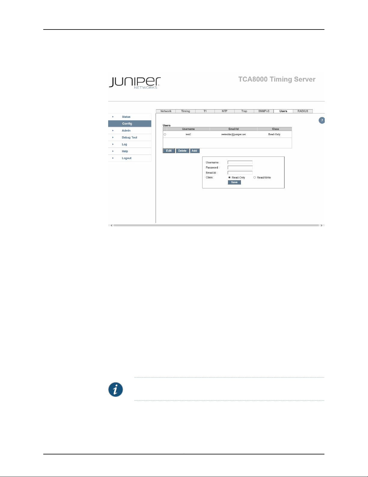
TCA8000 and TCA8500 Timing Server Installation and Configuration Guide
Figure 19: Timing Server Config Page—Users Pane
4. Click the Add button.
5. In the Username field, enter the username for the new user account.
6. In the Password field, enter the password for the new user account.
7. In the Email-Id field, enter the e-mail address for the new user account.
8. In the Class field, selectan option button to set the login class for the new user account
as Read-Only or Read/Write.
9. Click the Save button to create a new user account.
Modifying an Existing User Account
To modify an existing user account:
NOTE: You cannot modify the username.
1. Log in to the Timing Server as Admin user.
2. Click the Config tab.
Copyright © 2017, Juniper Networks, Inc.50
Page 67

Chapter 3: Configuring a TCA8000 or TCA8500 Timing Server
3. Locate the Users tab across the top tabs of the Config page. See Figure 19 on page 50.
4. In the Users window, select the user account to be modified.
5. Click the Edit button to populate the details of the selected user account in the
Username, Password, Email-Id, and Class fields.
6. Modify the password or class for the selected user account.
NOTE:
•
If you change the password, all the activesessions for the corresponding
user are not logged out. The user must use the new password for new
sessions.
•
If you change the class, all active sessions for the corresponding user
are logged out.
7. Click the Save button to save the changes done.
Deleting an Existing User Account
To delete an existing user account:
1. Log in to the Timing Server as Admin user.
2. Click the Config tab.
3. Locate the Users tab across the top tabs of the Config page. See Figure 19 on page 50.
4. In the Users window, select the user account to be deleted.
5. Click the Delete button to delete the selected user account.
NOTE: All active sessions for the deleted user are logged out.
Changing the Login Password for Read/Write User
The TCA8000 and TCA8500 timing servers allow Read/Write users to change their
password configured and shared by the TCA Admin user.
51Copyright © 2017, Juniper Networks, Inc.
Page 68

TCA8000 and TCA8500 Timing Server Installation and Configuration Guide
To change your (Read/Write user) password:
1. Log in to the Timing Server as Read/Write user.
2. Click the Config tab.
3. Locate the Profile tab across the top tabs of the Config page. See Figure 20 on page 52.
Figure 20: Timing Server Config Page—Profile Pane
4. In the Old Password field, enter your current password.
5. In the New Password field, enter the new password to replace the old password.
6. In the Retype New Password field, reenter the new password.
7. Click Save button to change your password and save the changes.
NOTE: The new password will be effective from next login onwards. The
current session is not affected.
Copyright © 2017, Juniper Networks, Inc.52
Page 69

Chapter 3: Configuring a TCA8000 or TCA8500 Timing Server
Configuring User Authentication through RADIUS
The TCA 8000 and TCA 8500 Timing Servers support RADIUS server authentication,
local authentication, or both based on the configured authentication order to authenticate
the user logging in to the Timing Server.
When you configure the authentication order as RADIUS server authentication followed
by the local authentication, the Timing Server passes the information about the logging
user to the configured RADIUS servers for authentication. If any one of the RADIUS server
successfully authenticates the user, then the Timing Server allows the user to log in. If
all the configured RADIUS servers fail to authenticate the user or configured RADIUS
servers are not available, then the Timing Server performs the local authentication and
allows the user to log in after successful local authentication. The Timing Server blocks
the logging user if both RADIUS and local authentication fails.
When you configure the authentication order as local authentication followed by the
RADIUS server authentication, the Timing Server performs the local authentication to
grant access to the logging user. If the local authentication fails to authenticate the user,
then the Timing Server passes the information about the logging user to the configured
RADIUS servers for authentication. If any one of the RADIUS server successfully
authenticates the user, then the Timing Server allows the user to log in. If all configured
RADIUS servers fail to authenticate the user, then the Timing Server denies access to
the logging user.
When you configure the authentication order as RADIUS server authentication only, the
Timing Server passes the information about the logging user to the configured RADIUS
servers for authentication. If any one of the RADIUS server successfully authenticates
the user, then the Timing Server allows the user to log in. If all configured RADIUS servers
fail to authenticate the user, then the Timing Server denies access to the logging user. If
all configured RADIUS servers are not available, then the Timing Server performs local
authentication and allows the user to log in after successful local authentication.
When you configure the authentication order as local authentication only, the Timing
Server performs the local authentication to grant or deny access to the user logging in
to the Timing Server.
NOTE:
•
The selection of RADIUS authenticationserver to authenticateuser is based
on the order in the RADIUS authentication server list.
•
The user authentication process is implemented only for the Access
Request, Access Reject, and Access Accept messages.
•
The user authentication process is not supported for shell users.
The user authentication process protects the Timing Server from being accessed by
unauthorized persons. The usage of RADIUS authentication servers providesthe following
advantages:
53Copyright © 2017, Juniper Networks, Inc.
Page 70
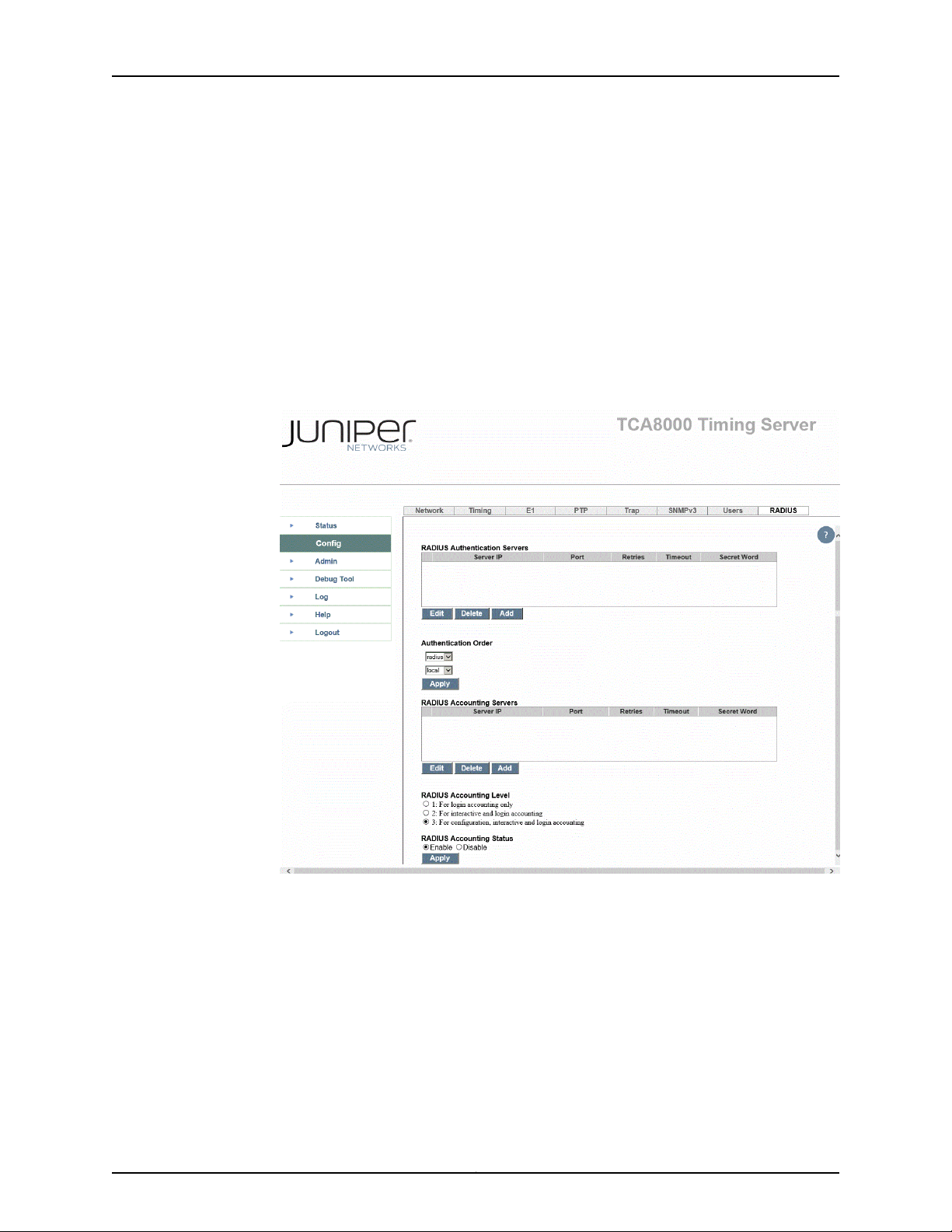
TCA8000 and TCA8500 Timing Server Installation and Configuration Guide
•
Management of multiple user credentials on remote machine for detailed logging.
•
Centralized user information and authentication process at one server.
•
No loss of user information due to Timing Server damage.
To configure user authentication process:
1. Click the Config tab.
2. Locate the RADIUS tab across the top tabs of the Config page. See
Figure 21 on page 54.
Figure 21: Timing Server Config Page—RADIUS Pane (Authentication)
3. Configure the RADIUS authentication server details.
4. Click the Save button to save the authentication server configuration.
Copyright © 2017, Juniper Networks, Inc.54
Page 71

5. Select the authentication order.
6. Click the Apply button to apply the configured authentication order.
The following sections describe RADIUS authentication server configuration and
authentication order configuration:
•
Adding a New RADIUS Authentication Server Entry on page 55
•
Deleting a RADIUS Authentication Server Entry on page 56
•
Modifying RADIUS Authentication Server Entry Details on page 56
•
Configuring Authentication Order on page 56
Adding a New RADIUS Authentication Server Entry
To add a new RADIUS authentication server entry to the authentication server list:
1. Click the Config tab.
Chapter 3: Configuring a TCA8000 or TCA8500 Timing Server
2. Locate the RADIUS tab across the top tabs of the Config page. See
Figure 21 on page 54.
3. In the Server IP field, enter the IP address of the RADIUS authentication server to be
used for user authentication.
4. In the Port field, enter the port through which the specified RADIUS authentication
server is contacted for user authentication.
5. In the Retry field, enter the number of attempts should be made for contacting the
specified RADIUS authentication server.
6. In the Timeout field, enter the time in seconds till which the Timing Server waits for
a response from the specified RADIUS authentication server.
7. In the Secret Word field, enter the password shared with the specified RADIUS
authentication server.
8. Click the Save button to add the RADIUS authentication server entry in the RADIUS
Authentication Servers window and memory.
55Copyright © 2017, Juniper Networks, Inc.
Page 72

TCA8000 and TCA8500 Timing Server Installation and Configuration Guide
Deleting a RADIUS Authentication Server Entry
To delete a RADIUS authentication server entry from the authentication server list:
1. Click the Config tab.
2. Locate the RADIUS tab across the top tabs of the Config page. See
Figure 21 on page 54.
3. In the RADIUS Authentication Servers window, click the RADIUS authentication
server entry to be deleted.
4. Click the Delete button to remove the entry from the RADIUS Authentication Server
window and memory.
Modifying RADIUS Authentication Server Entry Details
To modify the details of a RADIUS authentication server entry existing in the authentication
server list:
1. Click the Config tab.
2. Locate the RADIUS tab across the top tabs of the Config page. See
Figure 21 on page 54.
3. In the RADIUS Authentication Servers window, select the RADIUS authentication
server entry to be modified.
4. Click the Edit button to populate the values of the selected RADIUS authentication
server entry in the Server IP, Port, Retry, Timeout, and Secret Word fields.
5. Modify the populated values.
6. Click the Save button to save the changes done in the selected RADIUS authentication
server entry.
Configuring Authentication Order
To configure the authentication order:
1. Click the Config tab.
2. Locate the RADIUS tab across the top tabs of the Config page. See
Figure 21 on page 54.
3. In the first drop box, select the type of authentication to be performed initially. Select:
Copyright © 2017, Juniper Networks, Inc.56
Page 73

•
radius—To authenticate the user using the configured RADIUS authentication
servers.
•
local—To authenticate the user using local settings.
4. In the second drop box, select the type of authentication to be performed on failure
or unavailability of initial authentication. Select:
•
radius—To authenticate the user using the configured RADIUS authentication
servers.
•
local—To authenticate the user using local settings.
5. Click the Apply button to save the authentication order.
Configuring RADIUS Accounting
The TCA 8000 and TCA 8500 Timing Servers support RADIUS accounting for the user
logged in to the Timing Server. Once the user is logged in to the Timing Server, the Timing
Server passes the accounting information to the configured RADIUS accounting servers.
The Timing Server stops the accounting process when the user session is closed either
voluntarily or involuntarily. The Timing Server waits for acknowledgment from the
accounting servers for each accounting packet.
Chapter 3: Configuring a TCA8000 or TCA8500 Timing Server
When the RADIUS accounting is enabled, the Timing Server tries to log the accounting
information in any one of the configured RADIUS accounting server based on the
configured timeout period and number of retries. When the logging of accounting
information fails for all configured accounting server, the Timing Server raises an
ACCOUNTING_SERVER_UNAVAILABLE alarm.
When the RADIUS accounting server is unavailable, the accounting information (latest
15 commands) is buffered. The Timing Server sends the buffered information to the
RADIUS accounting server after the server becomes available.
The accounting process supports login accounting, interactive commands accounting,
and configuration commands accounting.
NOTE:
•
The selection of RADIUS accounting server to log the accounting
information is based on the order in the RADIUS accounting server list.
•
The accounting process is implemented only for the Accounting Request
and Accounting Response messages.
•
The RADIUS accounting is not supported for shell users.
•
The accounting process does not support immediate accounting and
accounting of web configurations.
The usage of RADIUS accounting servers provides the following advantages:
•
Centralized usage history of all users on one server.
57Copyright © 2017, Juniper Networks, Inc.
Page 74

TCA8000 and TCA8500 Timing Server Installation and Configuration Guide
•
No loss of usage history of users due to Timing Server damage.
To configure RADIUS accounting:
1. Click the Config tab.
2. Locate the RADIUS tab across the top tabs of the Config page. See
Figure 22 on page 58.
Figure 22: Timing Server Config Page—RADIUS Pane (Accounting)
3. In the RADIUS Accounting Status field, select the Enable option to enable RADIUS
accounting.
4. Click the Apply button to apply RADIUS accounting status configuration.
5. Configure the RADIUS accounting server details
6. Click the Save button to save the accounting server configuration.
Copyright © 2017, Juniper Networks, Inc.58
Page 75

7. In the RADIUS Accounting Level field, select the type of accounting information to
be logged in the RADIUS accounting server.
8. Click the Apply button to apply the configured RADIUS accounting level.
The following section describe RADIUS accounting server configuration:
•
Adding a New RADIUS Accounting Server Entry on page 59
•
Deleting a RADIUS Accounting Server Entry on page 59
•
Modifying RADIUS Accounting Server Entry Details on page 60
Adding a New RADIUS Accounting Server Entry
To add a new RADIUS accounting server entry to the accounting server list:
1. Click the Config tab.
2. Locate the RADIUS tab across the top tabs of the Config page. See
Figure 22 on page 58.
Chapter 3: Configuring a TCA8000 or TCA8500 Timing Server
3. In the Server IP field, enter the IP address of the RADIUS accounting server to be used
for accounting.
4. In the Port field, enter the port through which the specified RADIUS accounting server
is contacted for accounting.
5. In the Retry field, enter the number of attempts should be made for contacting the
specified RADIUS accounting server.
6. In the Timeout field, enter the time in seconds till which the Timing Server waits for
a response from the specified RADIUS accounting server.
7. In the Secret Word field, enter the password shared with the specified RADIUS
accounting server.
8. Click the Save button to add the RADIUS accounting server entry in the RADIUS
Accounting Servers window and memory.
Deleting a RADIUS Accounting Server Entry
To delete a RADIUS accounting server entry from the accounting server list:
1. Click the Config tab.
2. Locate the RADIUS tab across the top tabs of the Config page. See
Figure 22 on page 58.
59Copyright © 2017, Juniper Networks, Inc.
Page 76

TCA8000 and TCA8500 Timing Server Installation and Configuration Guide
3. In the RADIUS Accounting Servers window, click the RADIUS accounting server entry
to be deleted.
4. Click the Delete button to remove the entry from the RADIUS Accounting Servers
window and memory.
Modifying RADIUS Accounting Server Entry Details
To modify the details of a RADIUS accounting server entry existing in the accounting
server list:
1. Click the Config tab.
2. Locate the RADIUS tab across the top tabs of the Config page. See
Figure 22 on page 58.
3. In the RADIUS Accounting Servers window, select the RADIUS accounting server
entry to be modified.
4. Click the Edit button to populatethe values of the selected RADIUS accounting server
entry in the Server IP, Port, Retry, Timeout, and Secret Word fields.
5. Modify the populated values.
6. Click the Save button to save the changes done in the selected RADIUS accounting
server entry.
Specifying Recipients for Alarm E-Mail Notifications
The TCA8000 and TCA8500 Timing Servers can e-mail alarm event messages directly
to users.
•
Adding a User to the E-Mail List on page 60
•
Removing a User from the Alarm Event Recipient List on page 62
Adding a User to the E-Mail List
To add a user to the list of e-mail recipients to whom the Timing Server sends alarm
events:
1. Click the Admin tab.
2. Locate the Alarm section across the top of the Admin page. See Figure 23 on page 61
and Figure 24 on page 62.
Copyright © 2017, Juniper Networks, Inc.60
Page 77

Chapter 3: Configuring a TCA8000 or TCA8500 Timing Server
3. In the Alarm Email Recipients section:
a. In the SMTP field, enter the IP Address or domain name of the e-mail server the
Timing Server will use to send e-mail messages.
b. In the User x field, enter the IP address or domain name of the user to which the
Timing Server will send alarm event information.
c. In the From field, enter the IP address or domain name of the from address which
the Timing Server will use to send e-mail messages.
4. Click the Apply button to save your changes.
Figure 23: Timing Server Admin Page—Alarm Pane (PTP)
61Copyright © 2017, Juniper Networks, Inc.
Page 78

TCA8000 and TCA8500 Timing Server Installation and Configuration Guide
Figure 24: Timing Server Admin Page—Alarm Pane (NTP)
Removing a User from the Alarm Event Recipient List
To remove a user from the list of recipients who receive alarm events:
1. Click the Admin tab.
2. Locate the Alarm section across the top of the Admin page. See Figure 23 on page 61
and Figure 24 on page 62.
3. In the Alarm Email Recipient section, locate the User field that contains the address
of the recipient you want to remove.
4. Highlight all addresses, and press the Delete key.
5. Click the Apply button to save your changes.
Copyright © 2017, Juniper Networks, Inc.62
Page 79

Resetting Factory Defaults
The TCA8000 and TCA8500 Timing Server parameters can be set to the factory default
parameters. To reset the unit to the factory default parameters:
1. Click the Admin tab.
2. Locate the Config tab across the top of the Config pane. See Figure 25 on page 63.
3. In the Configuration Operation section, click the Reset button next to the text “Reset
to manufacture configuration” to reset the parameters.
Figure 25: Timing Server Admin Page—Config Pane
Chapter 3: Configuring a TCA8000 or TCA8500 Timing Server
63Copyright © 2017, Juniper Networks, Inc.
Page 80
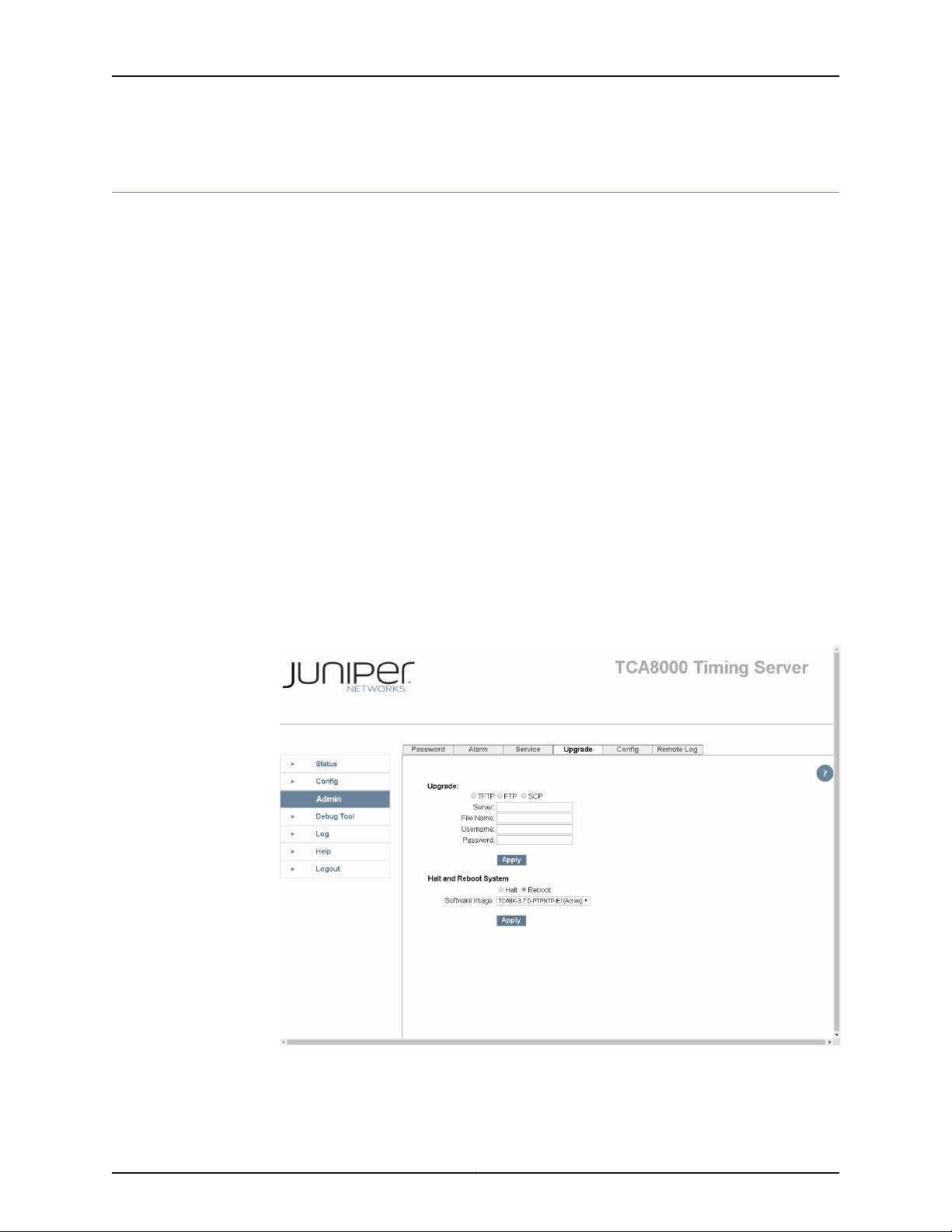
TCA8000 and TCA8500 Timing Server Installation and Configuration Guide
Stopping and Restarting the TCA8000 or TCA8500 Timing Server
You can reboot the TCA8000 or TCA8500 Timing Server, or perform a clean power
down by halting all the processes running on the Timing Server. To reboot or halt the
Timing Server:
1. Click the Admin tab.
2. Select the Upgrade tab at the top of the page.
3. Click the Reboot or Halt button.
4. Click Apply to reboot or halt the Timing Server.
The TCA8000 and TCA8500 Timing Servers provide carrier-class upgrade capability.
Two flash partitions are allocated to store software images. All upgrade or downgrade
images go to volatile RAM first, and are written to the inactive flash partition. The active
or non-active images can be selected to run on the Timing Server by selecting the image
using the drop-down arrow. After the unit has been rebooted, the new selected image
will be running.
Figure 26: Timing Server Admin Page—Upgrade Pane Showing the Current
Image
Copyright © 2017, Juniper Networks, Inc.64
Page 81
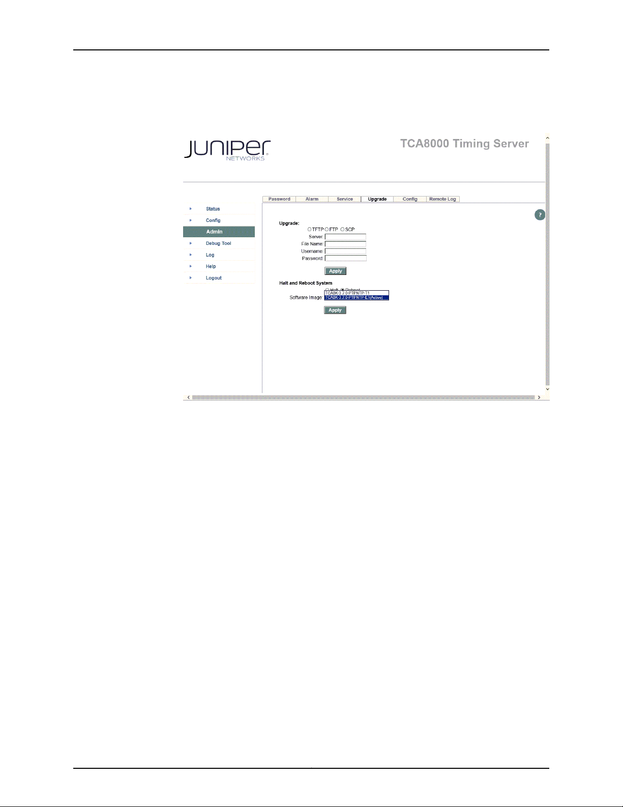
Chapter 3: Configuring a TCA8000 or TCA8500 Timing Server
Figure 27: Timing Server Admin Page—Upgrade Pane Showing the New
Image
65Copyright © 2017, Juniper Networks, Inc.
Page 82

TCA8000 and TCA8500 Timing Server Installation and Configuration Guide
Copyright © 2017, Juniper Networks, Inc.66
Page 83

CHAPTER 4
Upgrading the TCA8000 and TCA8500
Software
This chapter describes the processes for upgrading software on Juniper Networks
TCA8000 and TCA8500 Timing Servers. The following topics are discussed:
•
Upgrade Requirements on page 67
•
SelectingBetweenthe Pre-Installed Software Images Using a GUI/Browseron page 68
•
Upgrading the Software Using a GUI/Browser on page 69
•
Selecting Between the Pre-Installed Software Images Using the CLI on page 71
•
Upgrading the Software Using the CLI on page 72
•
Selecting Between the Pre-Installed Software Images Using the Hardware
Mechanism on page 73
Upgrade Requirements
The TCA8000 and TCA8500 Timing Servers are shipped with software pre-installed
and ready to be configured when the Timing Server is powered on. To upgrade the
software you must connect to the Timing Server using the GUI or a Telnet connection.
Upgrades affect service and cause the Timing Server to reboot. The Timing Server must
reboot to load the new software version. All timing outputs are interrupted during this
period (approximately 1-3 minutes). After the new version is loaded, frequency and time
lock can take up to 50 minutes to resume normal status (LOCKED) for PTP or NTP
features.
Gather the following information before upgrading the Timing Server:
•
Admin password
•
Name of the TFTP, FTP, or SCP server
•
IP address of the TFTP, FTP, or SCP server
•
Username and password of the FTP or SCP server
•
Filename of the software upgrade or downgrade image
67Copyright © 2017, Juniper Networks, Inc.
Page 84

TCA8000 and TCA8500 Timing Server Installation and Configuration Guide
Selecting Between the Pre-Installed Software Images Using a GUI/Browser
The TCA8000 and TCA8500 Timing Servers ship with both a T1 and E1 software image
installed in the two internal non-volatile memory partitions. By default, the TCA8000
and TCA8500 Timing Serversuse the E1 interfacetype. Youcan view the softwareimages
from the Timing Server Admin web interface page (see Figure 28 on page 71). The active
softwareimage is displayedas (Active) in the Halt and Reboot System drop-down menu.
To select an alternate software image using the Web-based GUI:
1. Verify that the Timing Server is powered on.
2. Enter the IP address of the Timing Server into a web browser.
For example, https://10.1.0.42.
3. Log in to the Timing Server as admin.
Login: admin
Password: admin
4. Select the Admin tab from the menu on the left.
5. Select the required interface from the drop-down menu.
6. Select the Reboot option.
7. Click Apply to reboot the Timing Server.
8. Select Yes when prompted with the dialog box stating “Do you confirm a system
reboot system?” The Timing Server reboots and loads the selected software image.
NOTE: If the appropriate software image interface is not shown in either
softwareimage partitions, upgrade the in-active partition with the appropriate
software image, and then perform the reboot as described in “Upgrading the
Software Using a GUI/Browser” on page 69.
Copyright © 2017, Juniper Networks, Inc.68
Page 85

Upgrading the Software Using a GUI/Browser
To upgrade the TCA8000 and TCA8500 Timing Server using the Web-based GUI:
1. Verify that the Timing Server is powered on.
NOTE: Ensure that you have cleared the browser cache history.
2. Enter the IP address of the Timing Server into a web browser.
For example, https://10.1.0.42.
3. Log in to the Timing Server as admin.
Login: admin
Password: admin
Chapter 4: Upgrading the TCA8000 and TCA8500 Software
4. Select the Admin tab from the menu on the left.
5. Select the network protocol to be used for transferring the software upgrade or
downgrade image.
•
Select TFTP to download the software image from the server supporting TFTP.
•
Select FTP to download the software image from the server supporting FTP.
•
Select SCP to download the software image from the server supporting SCP.
6. In the server field, enter the IP address of the server that contains the softwareupgrade
or downgrade image.
For example, 10.1.0.52.
7. In the file name field:
•
Enter the name of the software image file supplied by Juniper Customer Support if
the image is to be downloaded from the TFTP or FTP server.
For example, TCA8K-Fridaytel3-PTP-E1.
•
Enter the name of the Juniper supplied software image file with the file path if the
image is to be downloaded from the SCP server.
For example, /build/tca/images/TCA8K-Fridaytel3-PTP-E1.
69Copyright © 2017, Juniper Networks, Inc.
Page 86

TCA8000 and TCA8500 Timing Server Installation and Configuration Guide
NOTE: Two flash partitions are allocated to store software images. These
can be used to store the same images or two different images should you
wish to revert to a previous version.
All upgrade or downgrade images are written in volatile RAM first, and are
loaded to the inactive flash partition. You can select active or non-active
images to run on the Timing Server by selecting the image using the
drop-down arrow. After the unit has been rebooted, the new selected
image will be running on the appliance.
8. In the user name field, enter a valid server username.
NOTE: The user name field is applicable only if the image is to be
downloaded from the SCP or FTP server.
9. In the password field, enter the password of the server username.
NOTE: The password field is applicable only if the image is to be
downloaded from the SCP or FTP server.
10. Select the Apply button. The browser status (bottom of webpage) shows the
download progress. After the image file is completely downloaded (typically 1-3
minutes), a dialog box appears with the message, “Upgrade successful. The new
software image will take effect after the system reboots!”
11. Select OK to acknowledge the upgrade message.
12. Select the Reboot option.
13. Click Apply to reboot the Timing Server.
14. Select Yes when prompted with the dialog box stating “Do you confirm a system
reboot system?” The Timing Server reboots and loads the new software image.
Copyright © 2017, Juniper Networks, Inc.70
Page 87

Chapter 4: Upgrading the TCA8000 and TCA8500 Software
Figure 28: Timing Server Admin Page—Upgrade Pane
Rebooting the Timing Server will invoke an upgrade if it completes successfully. If the
upgrade fails in a detectable manner, the upgrade or downgrade image is discarded, and
the Timing Server boots from the previous image. If the upgrade failed in a manner
detectable only during the booting sequence, the hardware recovery cycle interrupts the
process and the system reverts back to the previous image; the upgrade or downgrade
image is discarded.
Selecting Between the Pre-Installed Software Images Using the CLI
The TCA8000 and TCA8500 Timing Servers ship with both T1 and E1 software images
installed in the two internal non-volatile memory partitions. By default, the TCA8000
and TCA8500Timing Servers use the E1 interface type. Use the show partition command
to display the active and backup software images. The CLI displays the current software
image as Active.
To select an alternate software image using the CLI:
1. Verify that the Timing Server is powered on.
2. Connect to the Timing Server over a Telnet application.
>telnet 10.1.0.42
3. Enter the login and password.
>login: admin
Password: admin
71Copyright © 2017, Juniper Networks, Inc.
Page 88

TCA8000 and TCA8500 Timing Server Installation and Configuration Guide
4. Issue the en command, and then enter enable as the password.
>en
Password: enable
5. Issue the show partition command to verify that the software image appears in
Partition 1.
# show partition
Partition 1: cern-2.1.2-2-PTP-E1 (Active)
Partition 2: cern-2.1.2-2-PTP-T1
6. To initiate the reboot, issue the reboot partition-number command where
partition-number is the number of the partition you want to load. Type Y to confirm.
# reboot 2
Are you sure you want> to reboot? y/n
>Y
The appliance will reboot resulting in a “no service” condition.
NOTE: If the appropriate software image interface is not shown in either
softwareimage partitions, upgrade the in-active partition with the appropriate
software image, and then perform the reboot as described in “Upgrading the
Software Using the CLI” on page 72
Upgrading the Software Using the CLI
To upgrade the software using the CLI:
1. Verify that the TCA8000 and TCA8500 Timing Server is powered on.
2. Connect to the Timing Server over a Telnet application.
>telnet 10.1.0.42
3. Enter the login and password.
>login: admin
Password: admin
4. Issue the en command, and then enter enable as the password.
>en
Password: enable
5. Issue the corresponding CLI command to load the software into the partition, then
confirm the upgrade.
•
Issue the tftp tftp-ip-address filename command if you want to download the
software image from the TFTP server.
Copyright © 2017, Juniper Networks, Inc.72
Page 89

Chapter 4: Upgrading the TCA8000 and TCA8500 Software
# tftp 10.0.122.10 TCA8K-Fridaytel3-PTP-E1
Are you sure you want to upgrade? y/n
>Y
Please wait during file transfer...
upgrade successful!
The new software will take effective after the reboot
•
Issue the ftp ftpserverip filename username password command if you want to
download the software image from the TFTP server.
# ftp 10.0.122.10 TCA8K-Fridaytel3-PTP-E1 user_1 user123
Are you sure you want to upgrade? y/n
>Y
Please wait during file transfer...
upgrade successful!
The new software will take effective after the reboot
•
Issue the scp username scpserverip filename command if you want to download the
software image from the SCP server.
# scp user_1 10.209.164.21 /build/tca/images/TCA8K-Fridaytel3-PTP-E1
Password: ******
Are you sure you want to upgrade? y/n
>Y
Please wait during file transfer...
upgrade successful!
The new software will take effective after the reboot
6. Issue the show partition command to verify that the software image appears in
Partition 1.
# show partition
Partition 1: TCA8K-Fridaytel3-PTP-E1
Partition 2: TCA8k-3.3.0-3-PTP-E1(Active)
7. Issue the reboot 1 command to initiate the reboot, and then type Y to confirm.
# reboot 1
Are you sure you want> to reboot? y/n
>Y
The appliance will reboot resulting in a “no service” condition.
Rebooting the Timing Server will invoke an upgrade if it completes successfully. If the
upgrade fails in a detectable manner, the upgrade or downgrade image is discarded, and
the Timing Server boots from the previous image. If the upgrade failed in a manner
detectable only during the booting sequence, the hardware recovery cycle interrupts the
process and the system reverts back to the previous image; the upgrade or downgrade
image is discarded.
SelectingBetween the Pre-Installed SoftwareImages Using the Hardware Mechanism
The TCA8000 and TCA8500 Timing Servers are shipped with both T1 and E1 software
images installed in the two internal non-volatile memory partitions. By default, the
73Copyright © 2017, Juniper Networks, Inc.
Page 90

TCA8000 and TCA8500 Timing Server Installation and Configuration Guide
TCA8000and TCA8500 Timing Serversuse the E1 interfacetype and the active software
image is present in the partition 1. The LCD screen displays the partition 1 as Primary and
the partition 2 as Secondary under the Admin menu.
To select an alternate software image using the hardware mechanism:
1. Press the Menu button in the front panel of the Timing Server to display menus in the
LCD screen.
2. Press the appropriate SELECT buttons in the front panel to select the Admin menu
from the displayed menus.
3. Press the OK button in the front panel to display sub-menus for the selected Admin
menu in the LCD screen.
4. Press the appropriate SELECT buttons in the front panel to select the
Reboot-Secondary sub-menu for rebooting the Timing Server with the software
image present in the partition 2.
5. Press the OK button in the front panel to reboot the Timing Server with the selected
image.
NOTE: If the appropriate software image interface is not shown in either
software image partitions, upgrade the inactive memory partition with the
appropriate software image, and then perform the reboot as described in
“Upgrading the Software Using a GUI/Browser” on page 69 or “Upgrading
the Software Using the CLI” on page 72.
If the LCD configuration change functionality is disabled, the system does
not display the Admin menu in the LCD screen. In such scenario, you cannot
use the hardware mechanism for rebooting the Timing Server.
Copyright © 2017, Juniper Networks, Inc.74
Page 91

PART 4
Understanding the TCA8000 and
TCA8500 Graphical User Interface (GUI)
•
Understanding the TCA8000 and TCA8500 Login Page on page 77
•
Understanding the TCA8000 and TCA8500 System Status Page on page 81
•
Understanding the TCA8000 and TCA8500 Config Page on page 99
•
Understanding the TCA8000 and TCA8500 Admin Page on page 129
•
Understanding the TCA8000 and TCA8500 Debug Tool Page on page 143
•
Understanding the TCA8000 and TCA8500 Log Page on page 147
75Copyright © 2017, Juniper Networks, Inc.
Page 92

TCA8000 and TCA8500 Timing Server Installation and Configuration Guide
Copyright © 2017, Juniper Networks, Inc.76
Page 93

CHAPTER 5
Understanding the TCA8000 and
TCA8500 Login Page
This chapter describes the Login page for the Juniper Networks TCA8000 and TCA8500
Timing Servers. The following topics are discussed:
•
Login Page Description on page 77
•
Accessing the Login Page on page 77
•
Understanding the Login Page on page 78
Login Page Description
The Login page appears when the TCA8000 or TCA8500 Timing Server is accessed.
The Login page provides information about the Timing Server configuration and other
relevant details.
Accessing the Login Page
To access the TCA8000 or TCA8500 Timing Server Login page:
1. Open an Internet browser on a computer.
2. In the address field, enter the IP address that has been assigned to the Timing Server,
and select Go.
The Login page appears. See Figure 29 on page 78.
77Copyright © 2017, Juniper Networks, Inc.
Page 94
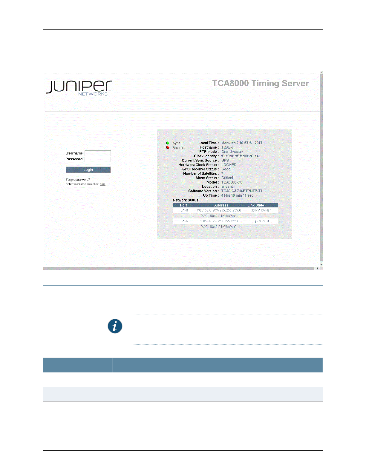
TCA8000 and TCA8500 Timing Server Installation and Configuration Guide
Figure 29: TCA8000 or TCA8500 Login Page
Understanding the Login Page
Table 4 on page 78 describes the elements that appear in the Login page of the TCA8000
and TCA8500 Timing Servers.
NOTE: After the Login page opens, select the Refresh button in the browser
to update the page.
Table 4: Elements on the Timing Server Login Page
DescriptionElement
Enter the name to be used as a login to the Timing Server.Username
Enter the user password.Password
Click to access the Timing Server pages.Login button
Copyright © 2017, Juniper Networks, Inc.78
Page 95

Chapter 5: Understanding the TCA8000 and TCA8500 Login Page
Table 4: Elements on the Timing Server Login Page (continued)
DescriptionElement
Forgot password
Sync LED
Alarms LED
Local Time
Admin users will be prompted to contact JTAC with the MAC address to get the master password.
Upon logging in with the master password, the Admin user has to set a new password.
For non-admin users, click to get the new password in your e-mail by authenticating with your
username and e-mail ID.
Indicateswhether the Timing Server is providing time synchronizationto a device on the network.
•
Green—Indicates that the Timing Server is in the PTP or NTP lock state.
•
Amber—Indicates that the Timing Server is receiving PTP or NTP timing packets from the
TCA6000 or TCA6500 Timing Client and is in the Timing acquire state.
Indicates whether there are active alarms present on the Timing Server.
•
Green—Indicates that there are no active alarms on the Timing Server.
•
Red—Indicates that there is one or more active alarms on the Timing Server.
The time kept by the Timing Server clock.
NOTE: You must click the Refresh button in your browser to update the time.
The name assigned to the Timing Server.Hostname
Indicates that the Timing Server is a PTP grandmaster.PTP Mode
A unique 64-bit value identifies the clock.Clock Identity
Hardware Clock Status
GPS Receiver Status
Number of Satellites
Indicates the current sync source type.Current Sync Source
Indicates the synchronization status of the hardware clock.
•
Acquiring—Indicates hardware clock is in process to lock to a provisioned reference.
•
Locked—Indicates hardware clock is synchronized to the reference source.
•
Freerun—Indicates no reference is available.
•
Holdover—Indicates hardware clock is in holdover state after all references are disqualified.
Indicates the GPS receiver status of the Timing Server clock. States are as follows:
•
No GPS Time
•
Good—GPS receiver is tracking minimum of three satellites for position solution.
•
No Usable Satellites
•
Survey-in Progress—GPS board is in self-survey mode and waiting to complete 100%. Do
not move unit.
•
Position is Questionable—Saved stored position does not track to the GPS location while
tracking present moment.
•
Almanac not Complete—GPS constellation information not completely downloaded. Upon
initial power-on, can take up to 12.5 minutes.
Indicates the number of GPS satellites the Timing Server has located. All satellites may not be
visible.
79Copyright © 2017, Juniper Networks, Inc.
Page 96

TCA8000 and TCA8500 Timing Server Installation and Configuration Guide
Table 4: Elements on the Timing Server Login Page (continued)
DescriptionElement
Indicates whether there are active alarms in effect.Alarm Status
Specifies the Juniper Networks Timing Server model.Model
Displays the location of the Timing Server.Location
Indicates the software version of the Timing Server.Software Version
Indicate the uptime since the most recent power up.Up Time
This window provides network connection information of the Timing Server.Network Status Window
Indicates the port the Timing Server is using.Port
Address
Lists the IP address assigned to the Timing Server.
Lists the MAC address assigned to the Timing Server by the manufacturer.
Displays the status of the connection—up or down.State
Copyright © 2017, Juniper Networks, Inc.80
Page 97

CHAPTER 6
Understanding the TCA8000 and
TCA8500 System Status Page
This chapter describes the information provided on the TCA8000 or TCA8500 Status
page. The following topics are addressed:
•
Understanding System LEDs on page 81
•
Status Page Description on page 82
•
Accessing the Status Page on page 82
•
Understanding the Status Page on page 83
Understanding System LEDs
The TCA8000 and TCA8500 Timing Servers have four LEDs, which indicate:
Power (PWR)—Indicates that the Timing Server is receiving power
Critical (CRT)—Indicates that the Timing Server has generated a CRITICAL alarm
Major (MAJ)—Indicates that the Timing Server has generated a MAJOR alarm
Minor (MIN)—Indicates that the Timing Server has generated a MINOR alarm
•
Port LEDs on page 81
•
IEEE 1588-2008 Sync LED on page 81
Port LEDs
The network Ethernet port—LAN—has integrated Sync and Activity LEDs embedded in
the RJ45 connector.
IEEE 1588-2008 Sync LED
The SYNC LED provides a status indication of the IEEE 1588-2008 Link:
Yellow—Acquire State
Green—Frequency & Phase Lock State
81Copyright © 2017, Juniper Networks, Inc.
Page 98
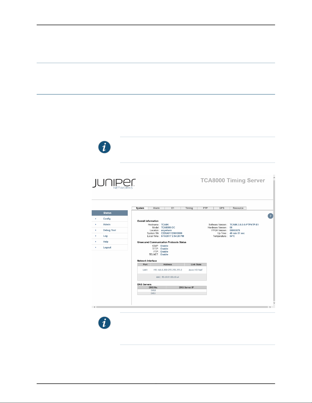
TCA8000 and TCA8500 Timing Server Installation and Configuration Guide
Status Page Description
The Status page provides operational and connectivity information for TCA8000 and
TCA8500 Timing Servers.
Accessing the Status Page
To access the Status page:
1. Log into a TCA8000 or TCA8500 Timing Server.
2. Click the Status tab. The Status page appears. See Figure 30 on page 82.
NOTE: Afterthe Status page opens, click the Refresh button in the browser
to update the page.
Figure 30: Timing Server Status Page—System Pane
NOTE: If the NTP support is enabled in the Timing Server, the Status page
displays the NTP tab instead of the PTP tab. By default, the PTP support
is enabled in the Timing Server.
Copyright © 2017, Juniper Networks, Inc.82
Page 99
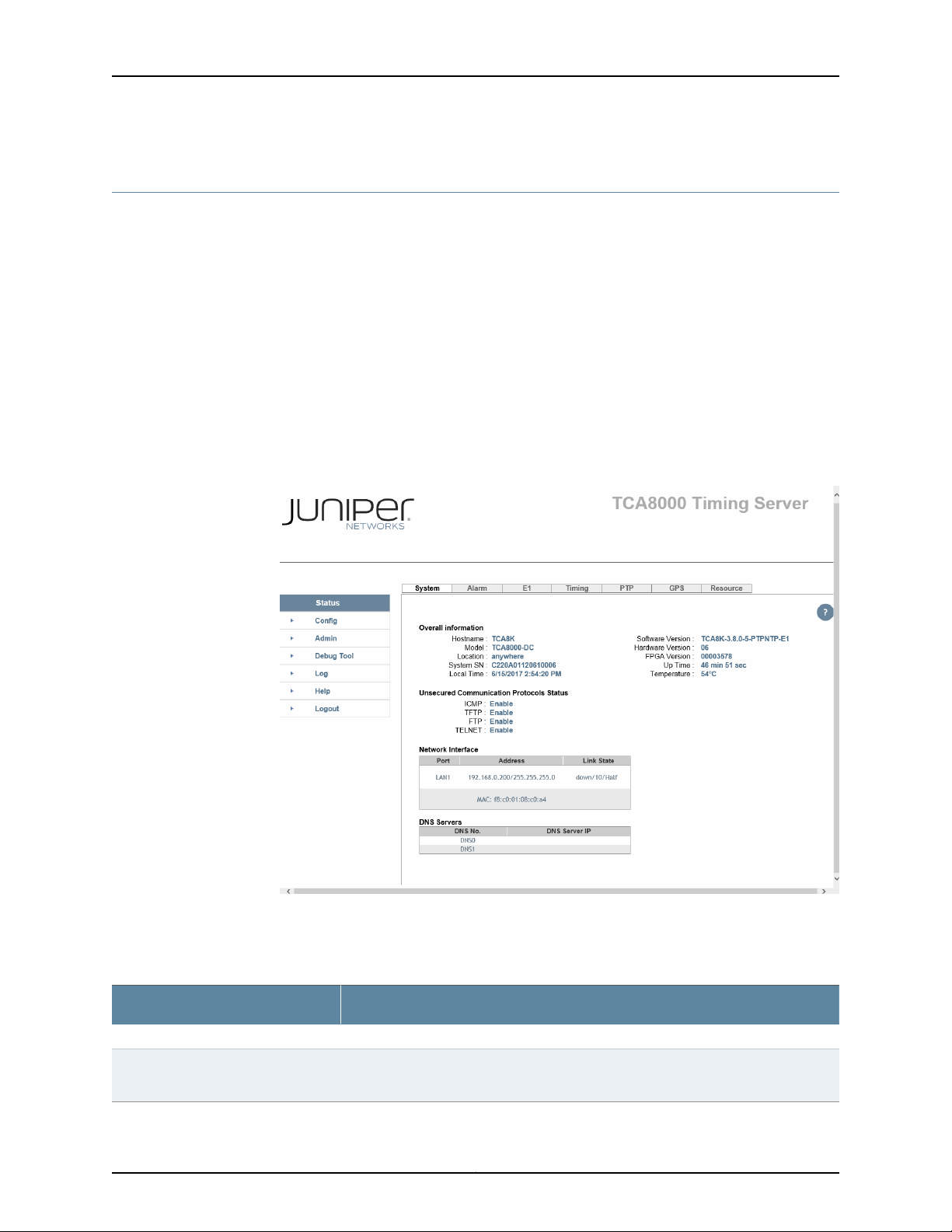
Understanding the Status Page
•
The Status Page–System Pane on page 83
•
The Status Page—Alarm Pane on page 85
•
The Status Page—E1 Pane on page 86
•
The Status Page—Timing Pane on page 88
•
The Status Page—PTP Pane on page 90
•
The Status Page—NTP Pane on page 93
•
The Status Page—GPS Pane (When GPS Option Is Connected) on page 95
•
The Status Page—Resource Pane on page 97
The Status Page–System Pane
Figure 31: Timing Server Status Page—System Pane
Chapter 6: Understanding the TCA8000 and TCA8500 System Status Page
Table 5 on page 83 describes the elements that appear on the Status page—System
Pane of the TCA8000 and TCA8500 Timing Servers.
Table 5: Elements on the Timing Server Status Page—System Pane
DescriptionElement
This section provides general information about the Timing Server.Overall Information Section
Hostname
The name assigned to the Timing Server. You can use the Admin page to assign a name
to the server.
83Copyright © 2017, Juniper Networks, Inc.
Page 100

TCA8000 and TCA8500 Timing Server Installation and Configuration Guide
Table 5: Elements on the Timing Server Status Page—System Pane (continued)
DescriptionElement
The model name of your Timing Server.Model
Indicates the physical location where the Timing Server is installed.Location
The serial number of the Timing Server motherboard.Board SN
The serial number of the Timing Server system assembly.System SN
Local Time
Unsecured Communication
Protocols Status Section
The time set on the clock of the Timing Server. Move your cursor over the date and
time, click and edit to change the date and time.
Indicates whether the LCD configuration change functionality is enabled or disabled.LCD Config Status
The version of software installed on the Timing Server.Software Version
The version of the Timing Server hardware.Hardware Version
The version of FPGA installed on the Timing Server.FPGA Version
Indicates how long the Timing Server has run since the last power up.Up Time
Shows the temperature of the Timing Server.Temperature
This section displays the status of unsecured transfer or communication
protocols.
Indicateswhether the Internet Control Message Protocol (ICMP) is enabled or disabled.ICMP
Indicates whether the Trivial File Transfer Protocol (TFTP) is enabled or disabled.TFTP
Indicates whether the FTP is enabled or disabled.FTP
Indicates whether the Telnet protocol is enabled or disabled.TELNET
This section provides information about the Timing Server network connections.Network Interface Section
Indicates the Timing Server port to which the address and state information pertains.Port
The IP address and MAC address used by the Timing Server port.Address
The connectivity state of the port with the network.State
This window lists the DNS servers the Timing Server is accessing.DNS Servers Window
Copyright © 2017, Juniper Networks, Inc.84
 Loading...