

Page 1

T640 Core Router Quick Start
January 2015
Part Number: 530-062015
Revision 01
This document describes how to install the Juniper Networks®T640 Core Router.
Contents
T640 Quick Start Description . . . . . . . . . . . . . . . . . . . . . . . . . . . . . . . . . . . . . . . . . . 3
Step 1: Preparing the Site . . . . . . . . . . . . . . . . . . . . . . . . . . . . . . . . . . . . . . . . . . . . . . 4
Rack-Mounting Requirements . . . . . . . . . . . . . . . . . . . . . . . . . . . . . . . . . . . . . . 4
Tools Required to Unpack and Prepare the T640 Router for Installation . . . . . 5
Step 2: Installing the Mounting Hardware . . . . . . . . . . . . . . . . . . . . . . . . . . . . . . . . . 7
Installing the Mounting Hardware for a Four-Post Rack or Cabinet . . . . . . . . . 7
Installing Cage Nuts, If Needed . . . . . . . . . . . . . . . . . . . . . . . . . . . . . . . . . . 8
Installing the Large Mounting Shelf and Spacer Bars . . . . . . . . . . . . . . . . 8
Installing the Small Mounting Shelf . . . . . . . . . . . . . . . . . . . . . . . . . . . . . . 9
Removing the Center-Mounting Brackets . . . . . . . . . . . . . . . . . . . . . . . . . . 9
Installing the Mounting Hardware in an Open-Frame Rack . . . . . . . . . . . . . . . 9
Installing Cage Nuts if Needed . . . . . . . . . . . . . . . . . . . . . . . . . . . . . . . . . . 11
Installing the Large Mounting Shelf . . . . . . . . . . . . . . . . . . . . . . . . . . . . . . 11
Removing the Spacer Bars and Center-Mounting Brackets . . . . . . . . . . . 11
Step 3: Installing the Router . . . . . . . . . . . . . . . . . . . . . . . . . . . . . . . . . . . . . . . . . . . 12
Installing the Router Using a Lift . . . . . . . . . . . . . . . . . . . . . . . . . . . . . . . . . . . . 12
Installing the Router Without a Mechanical Lift . . . . . . . . . . . . . . . . . . . . . . . . 13
Removing Components . . . . . . . . . . . . . . . . . . . . . . . . . . . . . . . . . . . . . . . 13
Lifting the Router into the Rack . . . . . . . . . . . . . . . . . . . . . . . . . . . . . . . . . 16
Reinstalling Components . . . . . . . . . . . . . . . . . . . . . . . . . . . . . . . . . . . . . . 18
Step 4: Connecting the Grounding Cable . . . . . . . . . . . . . . . . . . . . . . . . . . . . . . . . 18
Step 5: Connecting External Devices and PIC Cables . . . . . . . . . . . . . . . . . . . . . . . 20
Connecting a Management Device . . . . . . . . . . . . . . . . . . . . . . . . . . . . . . . . . 20
Connecting to a Network for Out-of-Band Management . . . . . . . . . . . . . . . . 21
Connecting the PIC Cables . . . . . . . . . . . . . . . . . . . . . . . . . . . . . . . . . . . . . . . . 21
1Copyright © 2015, Juniper Networks, Inc.
Page 2

T640 Core Router Quick Start
Step 6: Connecting Power . . . . . . . . . . . . . . . . . . . . . . . . . . . . . . . . . . . . . . . . . . . . 22
Connecting Power to a T640 Router with Two-Input 160-A DC Power
Supplies . . . . . . . . . . . . . . . . . . . . . . . . . . . . . . . . . . . . . . . . . . . . . . . . . . . 22
Connecting Power to a T640 Router with Three-Input 240-A DC Power
Supplies . . . . . . . . . . . . . . . . . . . . . . . . . . . . . . . . . . . . . . . . . . . . . . . . . . . 24
Setting the Input Mode Switch on a Three-Input 240-A DC Power
Supply . . . . . . . . . . . . . . . . . . . . . . . . . . . . . . . . . . . . . . . . . . . . . . . . . 24
Replacingthe Cable Restrainton a Three-Input 240-A DC Power Supply
(Optional) . . . . . . . . . . . . . . . . . . . . . . . . . . . . . . . . . . . . . . . . . . . . . . 25
Connecting the DC Power Cables . . . . . . . . . . . . . . . . . . . . . . . . . . . . . . . 27
Connecting Power to a T640 Router with Four-Input 160-A DC Power
Supplies . . . . . . . . . . . . . . . . . . . . . . . . . . . . . . . . . . . . . . . . . . . . . . . . . . . 28
Connecting Power to a T640 Router with Six-Input DC Power Supplies . . . . 30
Connecting Power to a T640 Router with Three-Phase Delta AC Power
Supplies . . . . . . . . . . . . . . . . . . . . . . . . . . . . . . . . . . . . . . . . . . . . . . . . . . . 34
Connecting Power to a T640 Router with Three-Phase Wye AC Power
Supplies . . . . . . . . . . . . . . . . . . . . . . . . . . . . . . . . . . . . . . . . . . . . . . . . . . . 36
Step 7: Powering On the T640 Router . . . . . . . . . . . . . . . . . . . . . . . . . . . . . . . . . . 39
Powering On the DC-Powered Router . . . . . . . . . . . . . . . . . . . . . . . . . . . . . . . 39
Powering On the AC-Powered Router . . . . . . . . . . . . . . . . . . . . . . . . . . . . . . . . 41
Step 8: Performing the Initial Software Configuration . . . . . . . . . . . . . . . . . . . . . . 42
Entering Configuration Mode . . . . . . . . . . . . . . . . . . . . . . . . . . . . . . . . . . . . . . 42
Configuring User Accounts and Passwords . . . . . . . . . . . . . . . . . . . . . . . . . . . 42
Configuring System Attributes . . . . . . . . . . . . . . . . . . . . . . . . . . . . . . . . . . . . . 43
Committing the Configuration . . . . . . . . . . . . . . . . . . . . . . . . . . . . . . . . . . . . . 44
Safety Warnings . . . . . . . . . . . . . . . . . . . . . . . . . . . . . . . . . . . . . . . . . . . . . . . . . . . . 47
Compliance Statements for NEBS . . . . . . . . . . . . . . . . . . . . . . . . . . . . . . . . . . . . . 49
Compliance Statements for EMC Requirements . . . . . . . . . . . . . . . . . . . . . . . . . . 49
Canada . . . . . . . . . . . . . . . . . . . . . . . . . . . . . . . . . . . . . . . . . . . . . . . . . . . . . . . 49
European Community . . . . . . . . . . . . . . . . . . . . . . . . . . . . . . . . . . . . . . . . . . . . 49
Israel . . . . . . . . . . . . . . . . . . . . . . . . . . . . . . . . . . . . . . . . . . . . . . . . . . . . . . . . . 50
Japan . . . . . . . . . . . . . . . . . . . . . . . . . . . . . . . . . . . . . . . . . . . . . . . . . . . . . . . . . 50
United States . . . . . . . . . . . . . . . . . . . . . . . . . . . . . . . . . . . . . . . . . . . . . . . . . . 50
Junos OS Documentation and Release Notes . . . . . . . . . . . . . . . . . . . . . . . . . . . . . 51
Requesting Technical Support . . . . . . . . . . . . . . . . . . . . . . . . . . . . . . . . . . . . . . . . . 51
Self-Help Online Tools and Resources . . . . . . . . . . . . . . . . . . . . . . . . . . . . . . . 51
Opening a Case with JTAC . . . . . . . . . . . . . . . . . . . . . . . . . . . . . . . . . . . . . . . . 52
Revision History . . . . . . . . . . . . . . . . . . . . . . . . . . . . . . . . . . . . . . . . . . . . . . . . . . . . 52
Copyright © 2015, Juniper Networks, Inc.2
Page 3

T640 Quick Start Description
This Quick Start contains information you need to install and configure the router quickly.
For complete installation instructions, see the T640 Core Router Hardware Guide at
http://www.juniper.net/techpubs/hardware/.
WARNING: This Quick Start contains a summary of safetywarningsin “Safety
Warnings” on page47. For a complete list of warnings for this router, including
translations, see the T640 Core Router Hardware Guide at
http://www.juniper.net/techpubs/hardware/.
The router is shipped in a wooden crate. A wooden pallet forms the base of the crate.
The router chassis is bolted to this pallet. The shipping crate also contains an accessory
box and a Quick Start (this document).
T640 Quick Start Description
3Copyright © 2015, Juniper Networks, Inc.
Page 4

T640 Core Router Quick Start
Step 1: Preparing the Site
Before installing the router, make sure that the site meets all the power, environmental,
and clearance requirements. See the site preparation guidelines in the T640 Core Router
Hardware Guide.
•
Rack-Mounting Requirements on page 4
•
Tools Required to Unpack and Prepare the T640 Router for Installation on page 5
Rack-Mounting Requirements
•
You can install the router in many types of racks, including a four-post rack or cabinet
or an open-frame rack.
•
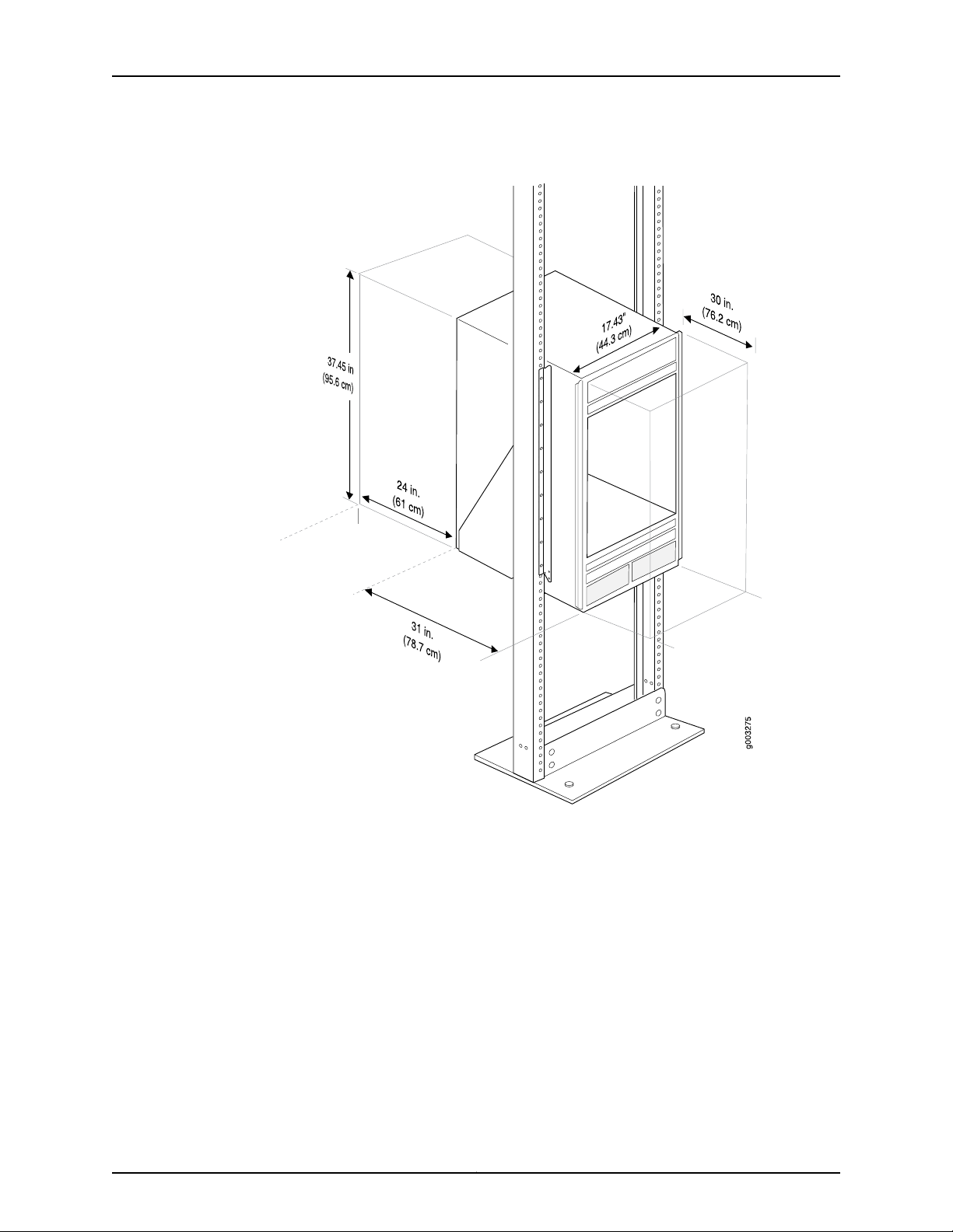
The rack rails must be spaced widely enough to accommodate the router chassis's
external dimensions: 37.45 in. (95.6 cm) high, 31 in. (78.7 cm) deep, and 17.43 in. (44.3
cm) wide. The mounting brackets extend the width to fit into standard 19-in. (48.3
cm) racks.
•
The rack must be strong enough to support the weight of the fully configured router,
up to about 565 lb (256.3 kg). If you mount two routers in one rack, it must be capable
of supporting a combined weight of over 1100 lb (499 kg).
•
For service personnel to remove and install hardware components, there must be
adequate space at the front and back of the router. Allow at least 24 in. (61.0 cm) both
in front of and behind the router.
•
The rack or cabinet must have an adequate supply of cooling air.
•
In a closed cabinet, there must be a minimum of 6 in. (15.2 cm) of unobstructed airflow
behind the router, or airflow baffles must be installed to prevent recirculation of hot
air and overheating.
•
If the router is the only unit in the rack, mount it at the bottom.
•
When mounting the router in a partially filled rack, load the rack from the bottom to
the top, with the heaviest component at the bottom of the rack.
Copyright © 2015, Juniper Networks, Inc.4
Page 5
Tools Required to Unpack and Prepare the T640 Router for Installation
Figure 1: Rack Clearances and Router Dimensions
Tools Required to Unpack and Prepare the T640 Router for Installation
•
A mechanical lift—recommended
•
1/2-in. or 13-mm open-end or socket wrench to remove bracket bolts from the shipping
pallet
•
Phillips screwdrivers, numbers 1 and 2
•
DC-powered routers: 7/16-in. (11 mm) hexagonal-head external drive nut driver, with
a torque range between 23 lb-in. (2.6 Nm) and 25 lb-in. (2.8 Nm), for tightening nuts
to terminal studs on each power supply on a DC-powered router
•
AC-powered router:
•
Phillips (+) screwdriver, number 2 to access the metal AC wiring compartment
5Copyright © 2015, Juniper Networks, Inc.
Page 6

T640 Core Router Quick Start
•
1/4-in. slotted screwdriver to attach the ground wire and input terminal wires of the
AC power cord.
•
Wire cutters
•
Cage nuts, if needed for your rack or cabinet
•
Electrostatic discharge wrist strap
•
Antistatic mat
•
Blank panels to cover any slots not occupied by a component
Copyright © 2015, Juniper Networks, Inc.6
Page 7
Step 2: Installing the Mounting Hardware
To install the mounting hardware:
•
Installing the Mounting Hardware for a Four-Post Rack or Cabinet on page 7
•
Installing the Mounting Hardware in an Open-Frame Rack on page 9
Installing the Mounting Hardware for a Four-Post Rack or Cabinet
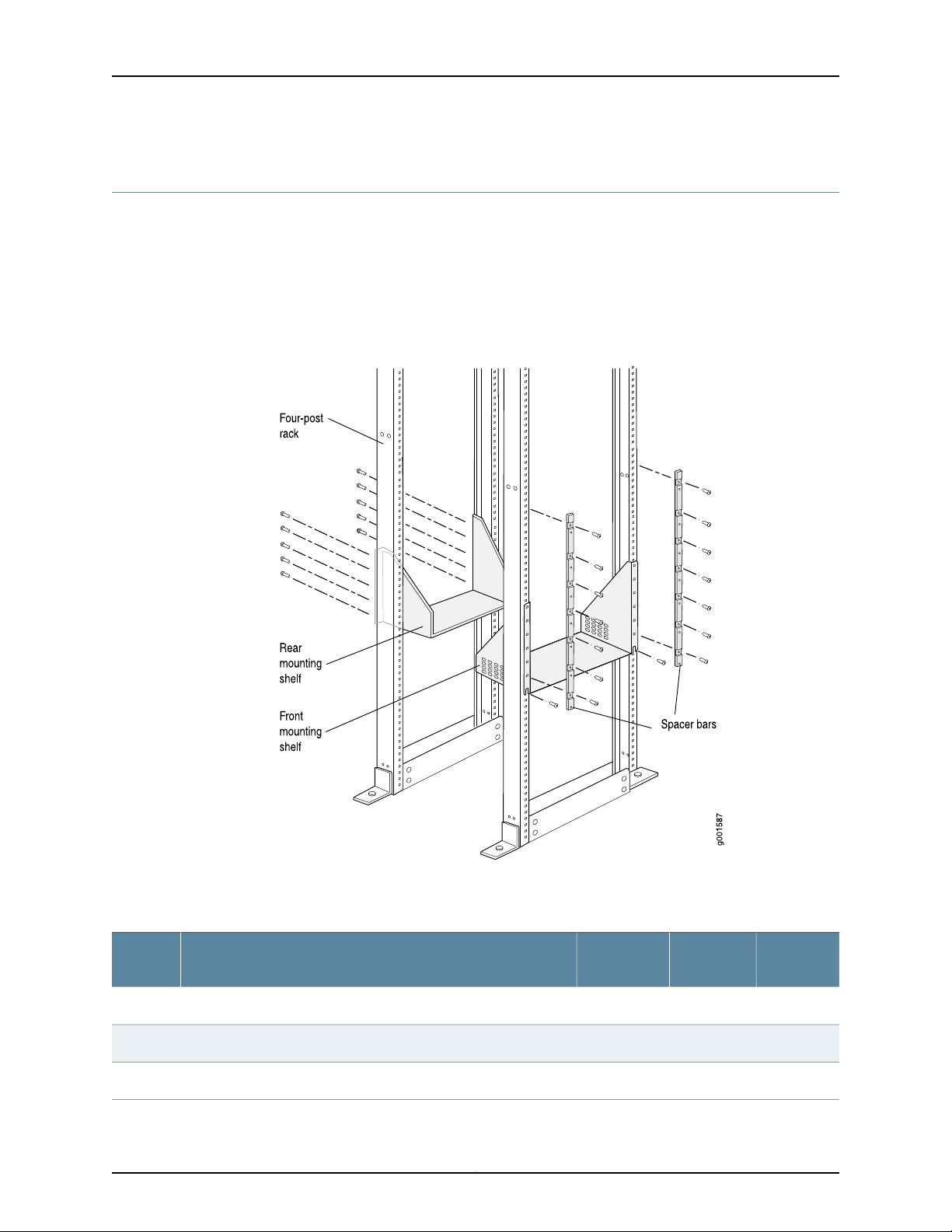
Figure 2: Mounting Hardware for a Four-Post Rack or Cabinet
Step 2: Installing the Mounting Hardware
An x in Table 1 on page 7 indicates a mounting hole location.
Table 1: Four-Post Rack and Cabinet Mounting Hole Locations
Spacer
BarsLarge ShelfDistance Above “U” DivisionHole
Small
Shelf
–x–19.86 U34.75 in. (88.3 cm)60
–x–16.86 U24.26 in. (61.6 cm)51
–x–13.86 U24.26 in. (61.6 cm)42
7Copyright © 2015, Juniper Networks, Inc.
Page 8

T640 Core Router Quick Start
Table 1: Four-Post Rack and Cabinet Mounting Hole Locations (continued)
To install the mounting hardware for a four-post rack or cabinet:
•
Installing Cage Nuts, If Needed on page 8
•
Installing the Large Mounting Shelf and Spacer Bars on page 8
•
Installing the Small Mounting Shelf on page 9
•
Removing the Center-Mounting Brackets on page 9
Spacer
BarsLarge ShelfDistance Above “U” DivisionHole
Small
Shelf
–x–10.86 U19.01 in. (48.3 cm)33
–x–7.86 U13.76 in. (34.9 cm)24
xx–4.86 U8.51 in. (21.6 cm)15
x––3.86 U6.76 in. (17.1 cm)12
x––4.86 U5.01 in. (12.7 cm)9
xx–1.86 U3.26 in. (8.3 cm)6
x––0.86 U1.51 in. (3.8 cm)3
––x0.5 U0.88 in. (2.2 cm)2
Installing Cage Nuts, If Needed
For racks without threaded holes, you must install cage nuts in the locations specified in
Table 1 on page 7:
•
On each front rack rail, install cage nuts for the large shelf and spacer bars.
•
On each rear rack rail, install cage nuts for the small shelf.
Installing the Large Mounting Shelf and Spacer Bars
1. On the front side of each front rail, partially insert a mounting screw into the lowest
hole specified in Table 1 on page 7 for the large shelf.
2. Install the large shelf on the front side of the front rack rails. Rest the bottom slot in
each flange on one of the mounting screws.
3. Tighten all the screws completely.
4. Place one spacer bar over a flange of the large shelf.
5. Partially insert a mounting screw into each of the nonthreaded holes in the recesses
of the spacer bar.
Copyright © 2015, Juniper Networks, Inc.8
Page 9

Installing the Small Mounting Shelf
6. Repeat Step 4 and Step 5 for the other spacer bar.
7. Tighten all the screws completely.
Installing the Small Mounting Shelf
The small shelf installs on the back of the rear rails, extending toward the center of the
rack. See Table 1 on page 7.
1. Partially insert a mounting screw into the lowest hole specified in Table 1 on page 7.
2. Install the small shelf on the back of the rear rack rails. Rest the bottom slot on each
flange on one of the mounting screws.
3. Partially insert screws into the open holes in the ears of the small shelf.
4. Tighten all the screws completely.
Removing the Center-Mounting Brackets
The router is shipped with a spacer bar attached to the back of each front-mounting
flange, and two center-mounting brackets attached to the chassis. Remove the center
mounting brackets from the chassis by loosening the screws at the top and bottom of
each bracket.
Installing the Mounting Hardware in an Open-Frame Rack
To install the mounting hardware for an open frame rack:
•
Front-mount: Attach the large mounting shelf on the back of the rails. Remove the
center-mounting brackets from the chassis.
•
Center mount: Attach the large mounting shelf on the back of the rails. You do not
have to remove the center-mounting brackets from the chassis.
The small mounting shelf is not needed for open-frame racks.Table 2 on page 10 specifies
the holes in which you insert mounting screws, and cage nuts if needed.
9Copyright © 2015, Juniper Networks, Inc.
Page 10

T640 Core Router Quick Start
Figure 3: Mounting Hardware for an Open-Frame Rack
An x in Table 2 on page 10 indicates a mounting hole location.
Table 2: Open-Frame Rack Mounting Hole Locations
Large ShelfDistance Above U DivisionHole
x19.5 U34.13 in. (86.7 cm)59
x17.5 U30.63 in. (77.8 cm)53
x16.5U28.88 in. (73.3 cm)50
x14.5 U25.38 in. (64.5 cm)44
x13.5 U23.63 in. (60.0 cm)41
x11.5 U20.13 in. (51.1 cm)35
x10.5 U18.38 in. (46.7 cm)32
Copyright © 2015, Juniper Networks, Inc.10
Page 11

Installing Cage Nuts if Needed
Table 2: Open-Frame Rack Mounting Hole Locations (continued)
Large ShelfDistance Above U DivisionHole
x10.14 U17.75 in. (45.1 cm)31
•
Installing Cage Nuts if Needed on page 11
•
Installing the Large Mounting Shelf on page 11
•
Removing the Spacer Bars and Center-Mounting Brackets on page 11
Installing Cage Nuts if Needed
Install cage nuts, if needed. On the back of the rack rails, install cage nuts for the large
shelf in the mounting holes specified in Table 2 on page 10.
Installing the Large Mounting Shelf
1. On the rear of each rack rail, partially insert a mounting screw in the lowest hole
specified in Table 2 on page 10.
2. Install the shelf on the rack. Rest the bottom slot in each flange on one of the installed
mounting screws.
3. Partially insert screws into the open holes in the flanges of the large shelf.
4. Tighten all the screws completely.
Removing the Spacer Bars and Center-Mounting Brackets
The router is shipped with a spacer bar attached to the back of each front-mounting
flange, and two center-mounting brackets attached to the chassis.
•
If you plan to front-mount the router in an open-frame rack:
1. Remove the spacer bars by loosening the screws that fasten the spacer bars to the
front-mounting flanges.
2. Remove the center-mounting brackets from the chassis by loosening the screws
at the top and bottom of each bracket.
•
If you plan to center-mount the router in an open-frame rack, leave the center-mounting
brackets attached to the chassis. Optionally, you can remove the spacer bars.
11Copyright © 2015, Juniper Networks, Inc.
Page 12

T640 Core Router Quick Start
Step 3: Installing the Router
Because of the router's size and weight, we recommend that you install the router using
a mechanical lift. If a lift is unavailable, see the instructions for installing the rack without
a mechanical lift.
•
Installing the Router Using a Lift on page 12
•
Installing the Router Without a Mechanical Lift on page 13
Installing the Router Using a Lift
CAUTION: Do not lift the router using the installation handle or the handles
on the sides of the chassis. Use these handles only to help position the router.
1. Make sure the rack is properly secured to the building in its permanent location.
2. Remove the power supplies from the router as described in the T640 Core Router
Hardware Guide.
3. Insert the captive screws of the installation handle into the holes previously occupied
by the captive screws of the power supplies. Attach the installation handle, tightening
the captive screws firmly to secure it to the chassis.
4. Load the router onto the lift, making sure it rests securely on the lift platform.
5. Using the lift, position the router in front of the rack or cabinet, centering it in front of
the large mounting shelf.
6. Carefully lower the router onto the shelf. The shelf ensures that the holes in the
mounting brackets align with the holes in the rack rails.
7. With one person pulling on the installation handle from the rear of the rack or cabinet
while another person pushes on the front-mounting flanges:
•
Four-post rack or cabinet: Slide the chassis onto the mounting shelves until the
front-mounting flanges contact the spacer bars.
•
Front-mounting in an open-frame rack: Slide the chassis onto the large mounting
shelf until the front-mounting flanges contact the rack rails.
•
Center-mounting in an open-frame rack: Slide the chassis onto the large mounting
shelf until the center-mounting brackets contact the rack rails.
8. Move the lift away from the rack.
9. Install the mounting screws:
•
Four-post rack or cabinet: Install a mounting screw into each of the holes aligned
with the threaded holes in the spacer bars.
•
Open-frame rack: Install a mounting screw into each of the open mounting holes
aligned with the rack, starting from the bottom.
10. Reinstall the power supplies as described in the T640 Core Router Hardware Guide.
Copyright © 2015, Juniper Networks, Inc.12
Page 13
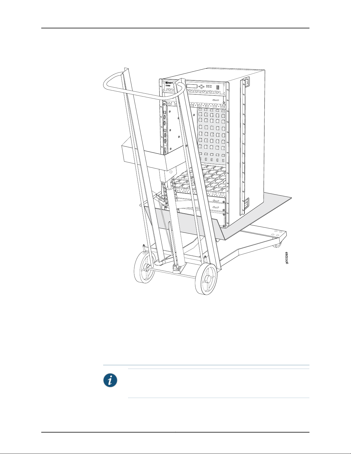
Figure 4: Loading the Router onto the Lift
Installing the Router Without a Mechanical Lift
Installing the Router Without a Mechanical Lift
To install the router without a mechanical lift:
•
Removing Components on page 13
•
Lifting the Router into the Rack on page 16
•
Reinstalling Components on page 18
Removing Components
NOTE: For complete instructions on removing router components, see the
T640 Core Router Hardware Guide.
13Copyright © 2015, Juniper Networks, Inc.
Page 14

T640 Core Router Quick Start
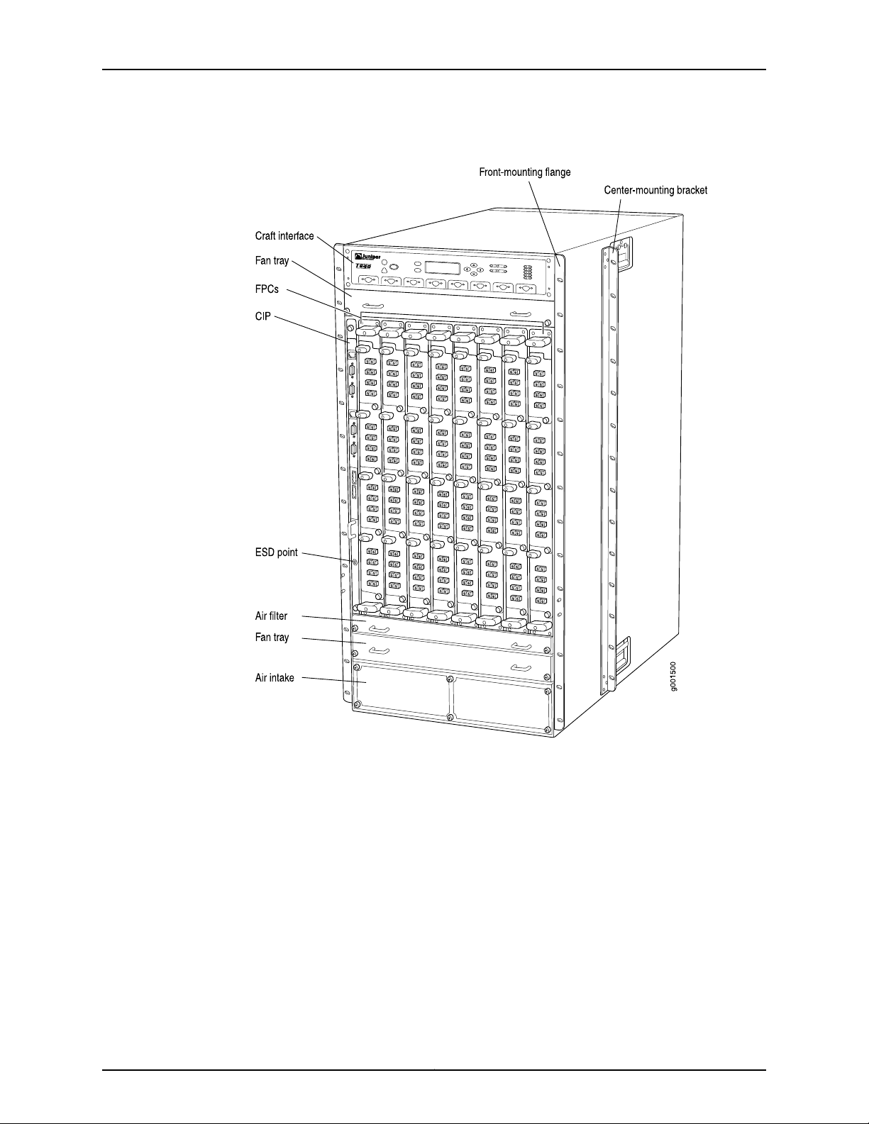
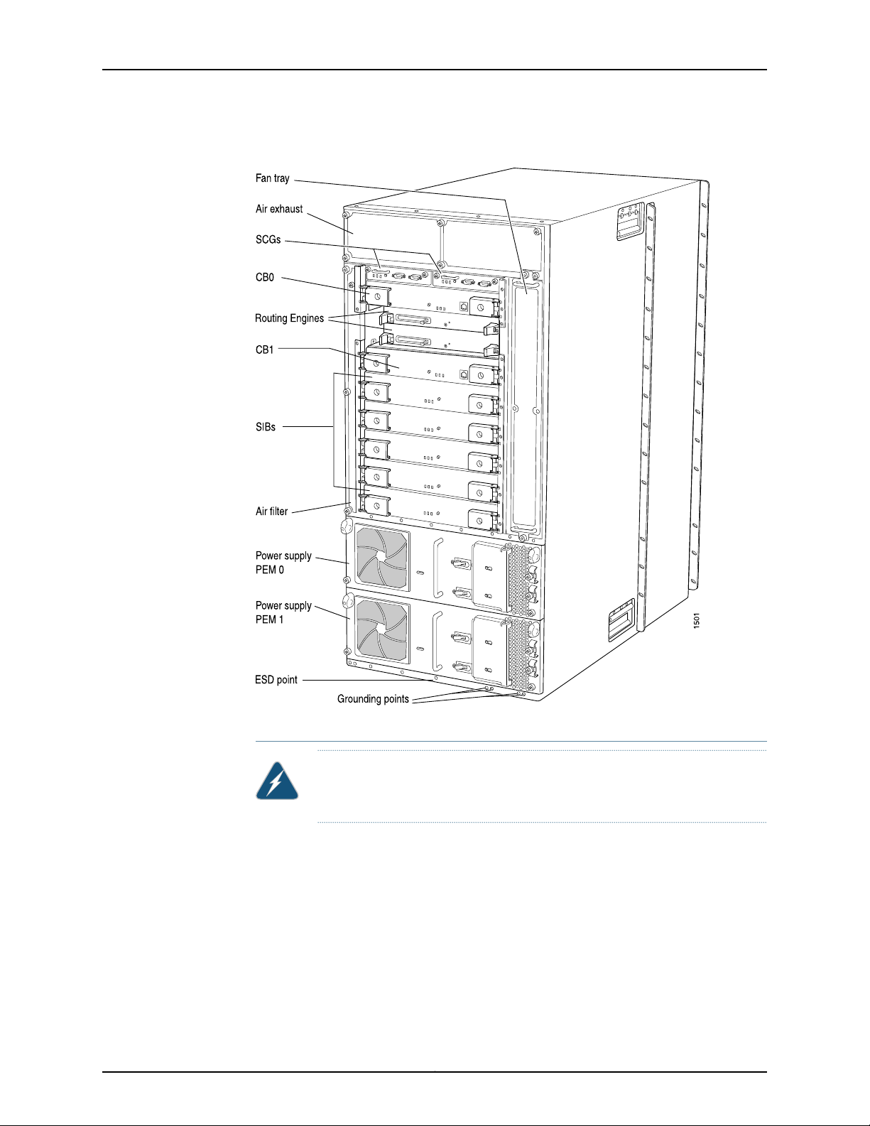
Before lifting the router, you must remove the following components (see
Figure 5 on page 15 and Figure 6 on page 16:
•
Power supplies
•
Cable management system
•
Switch Interface Boards (SIBs)
•
Control Boards (CBs)
•
SONET Clock Generators (SCGs)
•
Fan trays
•
Flexible PIC Concentrators (FPCs)
To remove the components from the router:
1. Slide each component out of the chassis evenly so that it does not become stuck or
damaged.
2. Label each component as you remove it so you can reinstall it in the correct location.
3. Immediately store each removed component in an electrostatic bag.
4. Do not stack removed components. Lay each one on a flat surface.
Copyright © 2015, Juniper Networks, Inc.14
Page 15
Removing Components
Figure 5: Components to Remove from the Front of the Router
15Copyright © 2015, Juniper Networks, Inc.
Page 16
T640 Core Router Quick Start
Figure 6: Components to Remove from the Rear of the Router
Lifting the Router into the Rack
WARNING: Do not lift the router using the installation handle or the handles
on the sides of the chassis. Use these handles only to help position the router.
Lifting the chassis and mounting it into a rack requires four people to lift and a fifth person
to secure the mounting screws. The empty chassis weighs over 205 lbs (64.7 kg).
1. Make sure the rack is in its permanent location and is secured to the building.
2. Insert the captive screws of the installation handle into the holes previously occupied
by the captive screws of the power supplies.
3. Move the router as close as possible to the rack. Use a pallet jack if one is available.
4. With two people in the front and two people in the back, hold the bottom of the chassis
and carefully lift it onto the large and small (if installed) mounting shelves.
Copyright © 2015, Juniper Networks, Inc.16
Page 17

Lifting the Router into the Rack
5. With one person pulling on the installation handle from the back of the rack or cabinet
while two people push on the front-mounting flanges, slide the router onto the
mounting shelf or shelves:
•
Four-post rack or cabinet: Slide the router onto the mounting shelves until the
front-mounting flanges contact the spacer bars.
•
Front-mounting in an open-frame rack: Slide the router onto the large mounting
shelf until the front-mounting flanges contact the rack rails.
•
Center-mounting in an open-frame rack: Slide the router onto the large mounting
shelf until the center-mounting brackets contact the rack rails.
6. If you are installing the router in a four-post rack or cabinet, install a mounting screw
and a cage nut into each of the holes aligned with the threaded holes in the spacer
bars. If you are installing the router into an open-frame rack, install a mounting screw
into each of the open mounting holes aligned with the rack, starting from the bottom.
Figure 7: Lifting the Router into the Rack
17Copyright © 2015, Juniper Networks, Inc.
Page 18

T640 Core Router Quick Start
Reinstalling Components
NOTE: For complete instructions on reinstalling router components after
you have installed the router without a mechanical lift, see the T640 Core
Router Hardware Guide.
1. Slide each component into the chassis evenly so that it does not become stuck or
damaged.
2. Tighten the captive screws for each component.
3. Make sure that all empty slots are covered with a blank panel before operating the
router.
Step 4: Connecting the Grounding Cable
You ground the router by connecting a grounding cable to earth ground and then attaching
it to the chassis grounding points with two screws. You must provide the grounding cable
(a cable lug is supplied with the router). To connect the grounding cable (see
Figure 8 on page 19):
1. Attachan electrostatic discharge (ESD) grounding strap to your bare wrist, and connect
the strap to an approved site ESD grounding point. See the instructions for your site.
2. Make sure that grounding surfaces are clean and brought to a bright finish before
grounding connections are made.
3. Connect the grounding cable to a proper earth ground.
4. Verify that a licensed electrician has attached the cable lug provided with the router
to the grounding cable.
5. Attach an electrostaticdischarge(ESD)grounding strap to your bare wrist, and connect
the strap to one of the ESD points on the chassis.
6. Place the grounding cable lug over the grounding points. The left pair is sized for M6
screws, and the right pair is sized for UNC 1/4-20 screws.
7. Secure the grounding cable lug to the grounding points, first with the washers, then
with the screws.
8. Verify that the grounding cabling is correct, that the grounding cable does not touch
or block access to router components, and that it does not drape where people could
trip on it.
Copyright © 2015, Juniper Networks, Inc.18
Page 19

Figure 8: Connecting the Grounding Cable
g006254
Grounding points
(on chassis)
Step 4: Connecting the Grounding Cable
19Copyright © 2015, Juniper Networks, Inc.
Page 20

T640 Core Router Quick Start
Step 5: Connecting External Devices and PIC Cables
Figure 9: Connecting External Devices and PIC Cables
To connect external devices and PIC cables:
•
Connecting a Management Device on page 20
•
Connecting to a Network for Out-of-Band Management on page 21
•
Connecting the PIC Cables on page 21
Connecting a Management Device
1. Locate the appropriate cable and connector.
2. Turn off the power switch on the management device.
Copyright © 2015, Juniper Networks, Inc.20
Page 21

3. Plug the female end of the RS-232 serial connector into the CONSOLE port or AUX
port on the Connector Interface Panel (CIP).
4. Plug the other end of the cable into the management device.
5. Tighten the screws on the connector.
Connecting to a Network for Out-of-Band Management
NOTE: Before you can use the Ethernet management port to connect to a
network for out-of-band management, you must perform the initial Junos
OS configuration after the router has been powered on. See “Step 8:
Performing the Initial Software Configuration” on page 42
1. Locate the appropriate cable and connector.
2. Plug one end of the Ethernet cable into the ETHERNET port on the CIP.
3. Plug the other end into the networking device.
Connecting to a Network for Out-of-Band Management
Connecting the PIC Cables
1. Identify the appropriate cable to be connected to each PIC.
WARNING: Do not look directly into the fiber-optic transceivers or into the
ends of fiber-optic cables.Fiber-optic transceiverscontainlaser light sources
that can damage your eyes.
CAUTION: To prevent damage to fiber-optic transceivers and fiber-optic
cables, observe the following precautions:
•
Do not leave a fiber-optic transceiver uncovered except when inserting or
removing cable. The safety cap keeps the port clean and prevents
accidental exposure to laser light.
•
Do not bend fiber-optic cable beyond its maximum bend radius. An arc
smaller than a few inches in diameter can damage the cable and cause
problems that are difficult to diagnose.
•
Do not let fiber-optic cable hang free from the connector. Do not allow
fastenedloopsof cable to dangle which stresses the cable at the fastening
point.
2. Insert the appropriate cable connector into the PIC cable receptacle.
3. Drape the cable over the bobbins of the cable management system to protect them
from bending past their recommended bend radius.
21Copyright © 2015, Juniper Networks, Inc.
Page 22

T640 Core Router Quick Start
Step 6: Connecting Power
For all other power supplies and connecting six 60-A input feeds to six inputs, see the
following topics for connection procedures.
•
Connecting Power to a T640 Router with Two-Input 160-A DC Power
Supplies on page 22
•
Connecting Power to a T640 Router with Three-Input 240-A DC Power
Supplies on page 24
•
Connecting Power to a T640 Router with Four-Input 160-A DC Power
Supplies on page 28
•
Connecting Power to a T640 Router with Six-Input DC Power Supplies on page 30
•
Connecting Power to a T640 Router with Three-Phase Delta AC Power
Supplies on page 34
•
Connecting Power to a T640 Router with Three-Phase Wye AC Power
Supplies on page 36
CAUTION:
See the T640 Core Router Hardware Guide for special considerations and
connection proceduresforthe followingpowerconfigurations for the six-input
power supply:
•
Five 60-A input feeds connecting to five inputs
•
Four 60-A input feeds connecting to four inputs
Connecting Power to a T640 Router with Two-Input 160-A DC Power Supplies
To connect DC power cables to the router:
1. Attachan electrostatic discharge (ESD) grounding strap to your bare wrist, and connect
the strap to an approved site ESD grounding point. See the instructions for your site.
2. Switch off the customer site circuit breakers. Make sure that the voltage across the
DC power source cable leads is 0 V and that there is no chance that the cable leads
might become active during installation. Follow your site's instructions for safety.
3. Verify that a licensed electrician has attached the cable lugs provided with the router
to the DC power cables.
4. Verify that the router is properly grounded.
5. Detach the ESD grounding strap from the approved site ESD grounding point, and
connect the strap to one of the ESD points on the chassis.
6. Verify that the circuit breakers on the power supply faceplate are in the OFF (O)
position.
7. Remove the clear plastic cover protecting the terminal studs on the power supply
faceplate.
Copyright © 2015, Juniper Networks, Inc.22
Page 23

Connecting Power to a T640 Router with Two-Input 160-A DC Power Supplies
8. Remove the nut and washer from the power terminal studs for INPUT O and INPUT 1.
9. Attach each power cable lug to the correct terminal stud on the power supply
faceplate, and secure the cable lug first with washer, then with the nut. Use a 7/16-in.
(11 mm) nut driver or wrench to tighten the nut. Apply between 23 lb-in. (2.6 Nm) and
25 lb-in. (2.8 Nm) of torque to each nut. (See Figure 10 on page 23, Figure 14 on page 28,
or Figure 15 on page 30.
CAUTION: You must use an appropriate torque-controlled tool to tighten
the nuts. Applying excessive torque damages the terminal studs and the
power supply. The absolute maximum torque that may be applied to this
nut is 45 in-lb (5.0 Nm).
a. Attach and secure the positive (+) cable lugs to the RTN (return) terminals.
b. Attach and secure the negative (–) cable lugs to the -48V (input) terminals.
10. Verifythatthe positive and negative power cables are connected to the correctterminal
studs.
11. Route the DC power cables through the cable restraint or restraints.
12. Tighten the cable restraint captive screw or screws to hold the power cables in place.
13. Replace the clear plastic cover on the power supply.
14. Repeat the procedure for the remaining power supply.
Figure 10: Connecting Power to a Two-Input 160-A DC Power Supply
23Copyright © 2015, Juniper Networks, Inc.
Page 24

T640 Core Router Quick Start
Connecting Power to a T640 Router with Three-Input 240-A DC Power Supplies
1.
Setting the Input Mode Switch on a Three-Input 240-A DC Power Supply on page 24
2.
Replacing the Cable Restraint on a Three-Input 240-A DC Power Supply
(Optional) on page 25
3.
Connecting the DC Power Cables on page 27
Setting the Input Mode Switch on a Three-Input 240-A DC Power Supply
NOTE: Do not set the input mode switch if the power supply is installed in
the chassis. If the power supply is already installed, you must disconnect all
cables and remove the power supply before setting the input mode switch.
To set the input mode switch (see Figure 11 on page 25):
1. Using a screwdriver, loosen the captive screw holding the metal cover over the input
mode switch (see Figure 11 on page 25).
2. Rotate the metal cover away from the input mode switch to expose the switch.
3. Check the setting of the input mode switch. Use a flashlight, if necessary. In 2-INPUT
mode, the switch must be positioned all the way to the right.
4. If the input mode switch is not set correctly, use a sharp, nonconductive object to slide
the switch all the way to the right to set the power supply to 2-INPUT mode.
CAUTION: Do not use a pencil, because fragments can break off and cause
damage to the power supply.
5. Rotate the metal cover over the input mode switch, and use a screwdriver to tighten
the captive screw.
Copyright © 2015, Juniper Networks, Inc.24
Page 25

Replacing the Cable Restraint on a Three-Input 240-A DC Power Supply (Optional)
Figure 11: Three-Input 240-A DC Power Supply in 2-INPUT Mode
Replacingthe CableRestraintona Three-Input 240-A DC Power Supply (Optional)
Each three-input 240-A DC power supply is shipped with the standard cable restraint
shown in Figure 12 on page 26. Two optional cable restraints are shipped in the accessory
box.
If your DC power cables are too large or inflexible to fit into the standard cable restraint,
we recommend that you remove the standard cable restraint and install the optional
cable restraint (see Figure 13 on page 26) on each three-input 240-A DC power supply.
To replace the cable restraint on a three-input 240-A DC power supply:
•
Removing the Standard Cable Restraint from a Three-Input 240-A DC Power
Supply on page 25
•
Installing the Optional Cable Restraint on a Three-Input 240-A DC Power
Supply on page 26
Removing the Standard Cable Restraint from a Three-Input 240-A DC Power Supply
The cable restraint is located on the right edge of the power supply faceplate. To remove
the standard cable restraint:
1. Loosen the captive screw on the standard cable restraint.
2. Remove the cable restraint from the power supply.
25Copyright © 2015, Juniper Networks, Inc.
Page 26

T640 Core Router Quick Start
Figure 12: Standard Cable Restraint on a Three-Input 240-A DC Power
Supply
Installing the Optional Cable Restraint on a Three-Input 240-A DC Power Supply
To install the optional cable restraint:
1. Align the two captive screws on the optional cable restraint with the two threaded
holes located at the right edge of the power supply faceplate.
2. Fasten the captive screws.
Figure 13: Optional Cable Restraint on a Three-Input 240-A DC Power
Supply
Copyright © 2015, Juniper Networks, Inc.26
Page 27

Connecting the DC Power Cables
Connecting the DC Power Cables
To connect DC power cables to the router:
1. Attachan electrostatic discharge (ESD) grounding strap to your bare wrist, and connect
the strap to an approved site ESD grounding point. See the instructions for your site.
2. Switch off the customer site circuit breakers. Make sure that the voltage across the
DC power source cable leads is 0 V and that there is no chance that the cable leads
might become active during installation. Follow your site's instructions for safety.
3. Verify that a licensed electrician has attached the cable lugs provided with the router
to the DC power cables.
4. Verify that the router is properly grounded.
5. Detach the ESD grounding strap from the approved site ESD grounding point, and
connect the strap to one of the ESD points on the chassis.
6. Verify that the circuit breakers on the power supply faceplate are in the OFF (O)
position.
7. Remove the clear plastic cover protecting the terminal studs on the power supply
faceplate.
8. Remove the nut and washer from the power terminal studs for INPUT O and INPUT 1.
NOTE: For a three-input 240-A DC power supply,INPUT2 is not supported
for the router and should not be connected.
9. Attach each power cable lug to the correct terminal stud on the power supply
faceplate, and secure the cable lug first with washer, then with the nut. Use a 7/16-in.
(11 mm) nut driver or wrench to tighten the nut. Apply between 23 lb-in. (2.6 Nm) and
25 lb-in. (2.8 Nm) of torque to each nut. (See Figure 10 on page 23, Figure 14 on page 28,
or Figure 15 on page 30.
CAUTION: You must use an appropriate torque-controlled tool to tighten
the nuts. Applying excessive torque damages the terminal studs and the
power supply. The absolute maximum torque that may be applied to this
nut is 45 in-lb (5.0 Nm).
a. Attach and secure the positive (+) cable lugs to the RTN (return) terminals.
b. Attach and secure the negative (–) cable lugs to the -48V (input) terminals.
10. Verifythatthe positive and negative power cables are connected to the correctterminal
studs.
11. Route the DC power cables through the cable restraint or restraints.
12. Tighten the cable restraint captive screw or screws to hold the power cables in place.
27Copyright © 2015, Juniper Networks, Inc.
Page 28

T640 Core Router Quick Start
13. Replace the clear plastic cover on the power supply.
14. Repeat the procedure for the remaining power supply.
Figure 14: Connecting Power to the Three-Input 240-A DC Power Supply
Connecting Power to a T640 Router with Four-Input 160-A DC Power Supplies
To connect DC power cables to the router:
1. Attachan electrostatic discharge (ESD) grounding strap to your bare wrist, and connect
the strap to an approved site ESD grounding point. See the instructions for your site.
2. Switch off the customer site circuit breakers. Make sure that the voltage across the
DC power source cable leads is 0 V and that there is no chance that the cable leads
might become active during installation. Follow your site's instructions for safety.
3. Verify that a licensed electrician has attached the cable lugs provided with the router
to the DC power cables.
4. Verify that the router is properly grounded.
5. Detach the ESD grounding strap from the approved site ESD grounding point, and
connect the strap to one of the ESD points on the chassis.
6. Verify that the circuit breakers on the power supply faceplate are in the OFF (O)
position.
Copyright © 2015, Juniper Networks, Inc.28
Page 29

Connecting Power to a T640 Router with Four-Input 160-A DC Power Supplies
7. Remove the clear plastic cover protecting the terminal studs on the power supply
faceplate.
8. Remove the nut and washer from the power terminal studs for INPUT O, INPUT 1,
INPUT 2, and INPUT 3.
NOTE: For a four-input 240-A DC power supply, all four inputs are
connected.
9. Attach each power cable lug to the correct terminal stud on the power supply
faceplate, and secure the cable lug first with washer, then with the nut. Use a 7/16-in.
(11 mm) nut driver or wrench to tighten the nut. Apply between 23 lb-in. (2.6 Nm) and
25 lb-in. (2.8 Nm) of torque to each nut. (See Figure 10 on page 23, Figure 14 on page 28,
or Figure 15 on page 30.
CAUTION: You must use an appropriate torque-controlled tool to tighten
the nuts. Applying excessive torque damages the terminal studs and the
power supply. The absolute maximum torque that may be applied to this
nut is 45 in-lb (5.0 Nm).
a. Attach and secure the positive (+) cable lugs to the RTN (return) terminals.
b. Attach and secure the negative (–) cable lugs to the -48V (input) terminals.
10. Verifythatthe positive and negative power cables are connected to the correctterminal
studs.
11. Route the DC power cables through the cable restraint or restraints.
12. Tighten the cable restraint captive screw or screws to hold the power cables in place.
13. Replace the clear plastic cover on the power supply.
14. Repeat the procedure for the remaining power supply.
29Copyright © 2015, Juniper Networks, Inc.
Page 30

g004661
Terminal studsCable lug
Locking
washer
Nut
T640 Core Router Quick Start
Figure 15: Connecting Power to the Four-Input 240-A DC Power Supply
Connecting Power to a T640 Router with Six-Input DC Power Supplies
You connect DC power to the router by attachingpowercablesfrom the DC power sources
to the terminal studs on the power supply faceplates. You must provide power cables
(the cable lugs are supplied with the router).
CAUTION: All connected inputs on the DC power supply in slot PEM0 must
be powered by dedicatedpowerfeedsderived from feed A, and all connected
inputs on the DC power supply in slot PEM1 must be powered by dedicated
power feeds derived from feed B. This configuration provides the commonly
deployed A/B feed redundancy for the system.
NOTE: We recommend that the positive (+) DC source power cables for the
RTN (return) terminals be 2.6 in. (6.6 cm) longer than the negative (–) DC
source power cables for the –48 V (input) terminals.
CAUTION: You must use an appropriate torque-controlled tool to tighten
the nuts. Applying excessive torque damages the terminal studs and the
power supply. The absolute maximum torque that may be applied to this nut
is 45 lb-in. (5.0 Nm).
Copyright © 2015, Juniper Networks, Inc.30
Page 31

Connecting Power to a T640 Router with Six-Input DC Power Supplies
CAUTION: You must ensure that power connections maintain the proper
polarity. The power source cables might be labeled (+) and (–) to indicate
their polarity. There is no standard color coding for DC power cables. The
color coding used by the external DC power source at your site determines
the color coding for the leads on the power cables that attach to the terminal
studs on each power supply.
To connect DC source power cables to the router, follow this procedure for each DC
power supply:
1. Verify that a properly rated customer site circuit breaker for each DC power cable has
been installed. See the DC power electrical safety guidelines for your router for more
information.
2. Switch off the customer site circuit breakers. Ensure that the voltage across the DC
power source cable leads is 0 V and that there is no chance that the cable leads might
become active during installation.
3. Verify that a licensed electrician has attached appropriate cable lugs to the DC power
cables. See the DC power cable and lug specifications for your router for more
information.
4. Switch the power switch on the power supply faceplate to the standby position.
5. Remove the clear plastic cover protecting the terminal studs on the faceplate.
6. Remove the nut and washer from each power terminal stud to be connected. If no
washers and nuts are already installed, they should be in the accessory box.
7. Removethe captive screws on all three cable restraints on the right edge of the power
supply faceplate (using a Phillips (+) screwdriver, number 2).
8. Route the negative (–) DC source power cables for INPUT 0, INPUT 1, INPUT 3, and
INPUT 4 over the smallest cable restraint on the far right. The cable restraint is marked
as follows top to bottom: INPUT 0, INPUT 1, INPUT 3, and INPUT 4.
NOTE: You must route the cables in the locations as marked to be able
to replace the clear plastic cover over the terminal studs.
Attach the negative (–) DC source power cable lugs INPUT 0, INPUT 1, INPUT 3, and
INPUT 4 to the –48 V (input) terminals on the right. Secure the cable lugs to the
terminal studs, first with the washers, then with the nuts. Using a 7/16-in. (11 mm) nut
driver, tighten the nuts. Apply between 23 lb-in. (2.6 Nm) and 25 lb-in. (2.8 Nm) of
torque to each nut.
31Copyright © 2015, Juniper Networks, Inc.
Page 32

g006353
Terminal studs
Cable lug
Locking
washer
Nut
g006358
T640 Core Router Quick Start
Figure 16: Connecting DC Power Cables
Figure 17: Connecting Negative(–) DC Power Cables to INPUT 0, INPUT 1,
INPUT 3, and INPUT 4
9. Replace the smallest cable restraint on the far right, and tighten the captive screw to
hold the power cables for INPUT 0, INPUT 1, INPUT 3, and INPUT 4 in place.
10. Route the negative (–) DC source power cables for INPUT 2 and INPUT 5 through the
middle cable restraint. The middle cable restraint is marked as follows from top to
bottom: INPUT 2, RTN 2, RTN 5, and INPUT 5.
NOTE: You must route the cables in the locations as marked to be able
to replace the clear plastic cover over the terminal studs.
Attach the negative (–) DC source power cable lugs to the –48 V (input) terminals
on the right. Secure the cable lugs to the terminal studs, first with the washers, then
with the nuts. Using a 7/16-in. (11 mm) nut driver, tighten the nuts. Apply between 23
lb-in. (2.6 Nm) and 25 lb-in. (2.8 Nm) of torque to each nut.
Copyright © 2015, Juniper Networks, Inc.32
Page 33

g006354
Connecting Power to a T640 Router with Six-Input DC Power Supplies
Figure 18: Connecting Negative (–) DC Power Cables to INPUT 2 and
INPUT 5
11. Route the positive (+) DC source power cables for RTN 2 and RTN 5 over the middle
cable restraint. The middle cable restraint is marked as follows from top to bottom:
INPUT 2, RTN 2, RTN 5, and INPUT 5.
NOTE: You must route the cables as marked to be able to replace the
clear plastic cover over the terminal studs.
Attach the positive (+) DC source power cable lugs RTN 2 and RTN 5 to the RTN
(return) terminals on the left. Secure the cable lugs to the terminal studs, first with
the washers, then with the nuts. Using a 7/16-in. (11 mm) nut driver, tighten the nuts.
Apply between 23 lb-in. (2.6 Nm) and 25 lb-in. (2.8 Nm) of torque to each nut.
12. Replace the middle cable restraint, and tighten the captive screw to hold the power
cables for INPUT 2, INPUT 5, RTN 2, and RTN 5 in place.
13. Route the positive (+) DC source power cables for RTN 0, RTN 1, RTN 3, and RTN 4
over the largest cable restraint on the left. The left cable restraint is marked as follows
from top to bottom: RTN 0, RTN 1, RTN 3, and RTN 4.
NOTE: You must route the cables as marked to be able to replace the
clear plastic cover over the terminal studs.
Attach the positive (+) DC source power cable lugs to the RTN 0, RTN 1, RTN 3, and
RTN 4 terminals on the left. Secure the cable lugs to the terminal studs, first with the
washers, then with the nuts. Using a 7/16-in. (11 mm) nut driver, tighten the nuts. Apply
between 23 lb-in. (2.6 Nm) and 25 lb-in. (2.8 Nm) of torque to each nut.
14. Replacethe left cable restraint,and tighten the captive screw to hold the power cables
for RTN 0, RTN 1, RTN 3, and RTN 4 in place.
33Copyright © 2015, Juniper Networks, Inc.
Page 34

g006355
T640 Core Router Quick Start
Figure 19: Connecting Positive (+) DC Power Cables to RTN 2, RTN 5,
RTN 0, RTN 1, RTN 3, and RTN 4
15. Verify that the power cabling is correct, that the power cables are not touching or
blocking accessto router components, and that they do not drape where people could
trip on them.
16. Replace the clear plastic cover over the terminal studs on the faceplate.
Connecting Power to a T640 Router with Three-Phase Delta AC Power Supplies
You connect AC power to the router with three-phase delta AC power supplies by
connecting the AC power cord from an AC power supply to an AC power source.
To connect an AC power cord to an AC power source:
1. Attachan electrostatic discharge (ESD) grounding strap to your bare wrist, and connect
the strap to an approved site ESD grounding point. See the instructions for your site.
2. Switch off the customer site circuit breakers. Ensure that the voltage across the AC
power source is 0 V and that there is no chance that the voltage might become active
during installation.
3. Detach the ESD grounding strap from the approved site ESD grounding point, and
connect the strap to one of the ESD points on the chassis.
4. Switch the power switch on the power supply faceplate to the standby position.
5. Using a number 2 Phillips (+) screwdriver, unscrew the two captive screws located
on the right side of the metal AC wiring compartment.
6. Open the metal door of the metal AC wiring compartment.
7. Unscrew the retaining nut from the AC power cord.
8. Place the retaining nut inside the metal wiring compartment.
9. Put the wires of the AC power cord through the hole of the metal wiring compartment.
10. Screw the retaining nut onto the AC power cord to secure it to the metal wiring
compartment.
Copyright © 2015, Juniper Networks, Inc.34
Page 35

L1 L2 L3
g004951
L1 L2 L3
Connecting Power to a T640 Router with Three-Phase Delta AC Power Supplies
11. Connect the wires to the AC terminal block on the three-phase delta AC power supply
(Figure 20 on page 35). Loosen the input terminal or grounding point screw, insert
each wire into the grounding point or input terminal, and tighten the screw.
NOTE: The terminal connections have either slottedscrewsor hex screws.
Use a 1/4-in. slotted screwdriver for the slotted screws. Use a 5/32-in
(4-mm) Allen wrench for the 5/ 16-in hex screws.
a. Insert the wire labeled GND into the grounding point labeled GND.
b. Insert the wire labeled L1 into the L1 input terminal.
c. Insert the wire labeled L2 into the L2 input terminal.
d. Insert the wire labeled L3 into the L3 input terminal.
Figure 20: Connecting Power to a Three-Phase Delta AC Power Supply
NOTE: The color of each AC power wire might vary.
12. Verify that the power cable connections are correct.
13. Using a number 2 Phillips (+) screwdriver, tighten the two captive screws on the metal
AC wiring compartment.
14. Use the provided plastic cable tie to fasten the AC power cord to the power supply.
35Copyright © 2015, Juniper Networks, Inc.
Page 36

T640 Core Router Quick Start
15. Verify that the AC power cord is not touching or blocking accessto router components,
and that it does not drape where people could trip on it.
16. Repeat the procedure for the other three-phase delta AC power supply.
Connecting Power to a T640 Router with Three-Phase Wye AC Power Supplies
To connect an AC power cord:
1. Attachan electrostatic discharge (ESD) grounding strap to your bare wrist, and connect
the strap to an approved site ESD grounding point. See the instructions for your site.
2. Switch off the customer site circuit breakers. Ensure that the voltage across the AC
power source is 0 V and that there is no chance that the voltage might become active
during installation.
3. Detach the ESD grounding strap from the approved site ESD grounding point, and
connect the strap to one of the ESD points on the chassis.
4. Switch the power switch on the power supply faceplate to the standby position.
5. Using a number 2 Phillips (+) screwdriver, loosen the two captive screws on the metal
AC wiring compartment.
6. Open the metal door of the metal AC wiring compartment.
7. Unscrew the retaining nut from the AC power cord.
8. Place the retaining nut inside the metal wiring compartment.
9. Put the wires of the AC power cord through the hole of the metal wiring compartment.
10. Screw the retaining nut onto the AC power cord to secure it to the metal wiring
compartment.
Copyright © 2015, Juniper Networks, Inc.36
Page 37

L1 L2 L3 N
g004950
g004953
Connecting Power to a T640 Router with Three-Phase Wye AC Power Supplies
11. Connect the wires to the AC terminal block on the three-phase wye AC power supply
(Figure 21 on page 37). Loosen each of the input terminals or grounding point screws,
insert each wire into the grounding point or input terminal, and tighten the screw.
NOTE: The terminal connections have either slottedscrewsor hex screws.
Use a 1/4-in. slotted screwdriver for the slotted screws. Use a 5/32-in
(4-mm) Allen wrench for the 5/ 16-in hex screws.
a. Insert the wire labeled GND into the grounding point labeled GND.
b. Insert the wire labeled L1 into the L1 input terminal.
c. Insert the wire labeled L2 into the L2 input terminal.
d. Insert the wire labeled L3 into the L3 input terminal.
e. Insert the wire labeled N into the N input terminal
Figure 21: Connecting Power to the Three-Phase Wye AC Power Supply
12. Verify that the power cable connections are correct.
13. Using a number 2 Phillips (+) screwdriver, tighten the two captive screws on the metal
AC wiring compartment.
14. Use the provided plastic cable tie to fasten the AC power cord to the power supply.
Figure 22: Fastening the AC Power Cord to the Power Supply
37Copyright © 2015, Juniper Networks, Inc.
Page 38

T640 Core Router Quick Start
15. Verify that the AC power cord is not touching or blocking accessto router components,
and that it does not drape where people could trip on it.
16. Repeat the procedure for the other three-phase wye AC power supply.
Copyright © 2015, Juniper Networks, Inc.38
Page 39

Step 7: Powering On the T640 Router
•
Powering On the DC-Powered Router on page 39
•
Powering On the AC-Powered Router on page 41
Powering On the DC-Powered Router
To power on the router:
1. Verify that the power supplies are fully inserted in the chassis and that the captive
screws on their faceplates are tightened.
2. Verify that the DC power cables are connected to the appropriate terminal —the
positive (+) source cable to the return terminal (labeled RTN) and the negative (–)
source cable to the input terminal (labeled -48V).
3. Verify that an external management device is connected to one of the Routing Engine
ports on the CIP (AUXILIARY or CONSOLE).
Step 7: Powering On the T640 Router
NOTE: The management Ethernet port will not be functional until you
have completed the initial configuration.
4. Turn on the power to the external management device.
5. Switch on the customer site circuit breakers to provide power to the DC power source
cable leads.
6. For a three-input 240-A DC power supply and six-input DC power supply, verify that
the INPUT PRESENT LED is lit steadily, indicating that the power supply is receiving
power.
NOTE: The two-input 160-A power supply does not have an INPUT
PRESENT LED.
7. For two-input 160-A DC power supplies, three-input 240-A DC power supplies, or
four-input 240-A DC power supplies, switch the circuit breakers on one of the power
supplies to the on position (|).
For six-input power supplies, switch the power switch on one of the power supplies
to the ON position (—). The DC OK LED blinks momentarily, then lights steadily.
NOTE: The Routing Engine boots as the power supply completesitsstartup
sequence.
8. For a two-input 160-A DC power supply, three-input 240-A DC power supply, or
four-input 240-A DC power supply, verify that the CB ON LED is lit steadily.
39Copyright © 2015, Juniper Networks, Inc.
Page 40

T640 Core Router Quick Start
NOTE: The six-input DC power supply does not have a CB ON LED.
9. Verify that the DC OK LED lights steadily, indicating that the power supply is correctly
installed and is functioning properly, The DC OK LED blinks momentarily after the
power switch or circuit breakers are switched to the on position, then lights steadily.
NOTE: After a power supply is powered on, it can take up to 60 seconds
for status indicators—suchasthe output status LEDs on the power supply,
the show chassis commands display output, and the messages on the
LCDon the craft interface—to indicatethat the power supply is functioning
normally. Ignore status indicators that appear during the first 60 seconds.
If any of the output status LEDs do not light steadily after a few minutes,
verify that the DC power cables are connected correctly. For three-input
240-A power supplies, verify that the input mode switch is correctly set
to two-input mode (see “Setting the Input Mode Switch on a Three-Input
240-A DC Power Supply” on page 24) and that the DC power cables are
connected to INPUT 0 and INPUT 1 only. If you are unable to correct the
problem, repeat the installation and cabling procedures.
10. Repeat Step 5 through Step 9 for the other power supply.
11. On the external management device connected to the Routing Engine, monitor the
startup process to verify that the system has booted properly.
NOTE: After powering on a power supply, wait at least 60 seconds before
turning it off. If the Routing Engine finishes booting and you need to power
down the router again, first issue the CLI request system haltcommand,
then wait for the following message:
Halt the system ? [yes,no] (no) yes
*** FINAL System shutdown message from root@section2 ***
System going down IMMEDIATELY
Terminated
...
syncing disks... 11 8 done
The operating system has halted.
Please press any key to reboot.
Copyright © 2015, Juniper Networks, Inc.40
Page 41

Powering On the AC-Powered Router
You can use this procedure for a router with either three-phase delta AC power supplies
or three-phase wye AC power supplies. To power on the AC-powered router:
1. Verify that the power supplies are fully inserted in the chassis and that the captive
screws on their faceplates are tightened.
2. Verify that the AC power cords are connected correctly.
3. Verify that an external management device is connected to one of the Routing Engine
ports on the CIP (AUXILIARY or CONSOLE).
NOTE: The management Ethernet port will not be functional until you
have completed the initial configuration.
4. Turn on the power to the external management device.
5. Switch on the dedicated customer site circuit breakers to provide power to the AC
power cables. Follow your site’s procedures.
Powering On the AC-Powered Router
6. Verify that the AC OK LED on both AC power supply faceplates are lit steadily green,
indicating that the power supplies are receiving power.
7. Attachan electrostatic discharge (ESD) grounding strap to your bare wrist, and connect
the strap to one of the ESD points on the chassis.
8. Switch the power switch on one of the power supplies to the ON position (|). The DC
OK LED blinks momentarily, then lights steadily.
NOTE: After a power supply is powered on, it can take up to 60 seconds
for status indicators—suchasthe output status LEDs on the power supply,
the command output, and messages on the LCD on the craft interface—to
indicate that the power supply is functioning normally. Ignore error
indicators that appear during the first 60 seconds.
9. Verify that the DC OK LED on the AC power supply faceplate is lit steadily, indicating
that power supply is correctly installed, functioning properly, and providing power to
the DC outputs.
10. On the external management device connected to the Routing Engine, monitor the
startup process to verify that the system has booted properly.
NOTE: If the systemis completely powered off when you power on the power
supply, the Routing Engine boots as the power supply completes its startup
sequence. If the Routing Engine finishes booting, you must power off the
router before powering it on again. After powering on a power supply, wait
at least 60 seconds before turning it off. After powering off a power supply,
wait at least 60 seconds before turning it back on.
41Copyright © 2015, Juniper Networks, Inc.
Page 42

T640 Core Router Quick Start
Step 8: Performing the Initial Software Configuration
The T640 Core Router is shipped with the Junos OS preinstalled and ready to be
configured when the T640 router is powered on. These procedures connect a router to
the network but do not enable it to forward traffic. For complete information about
enabling the router to forward traffic, including examples, see the Junos OS configuration
guides.
For the initial software configuration, issue Junos OS command-line interface (CLI)
commands on a console device attached to the CONSOLE port on the CIP.
NOTE: These procedures enable you to use the management Ethernet port.
For more information about the commands in this procedure see the Junos OS
Administration Library for Routing Devices.
1.
Entering Configuration Mode on page 42
2.
Configuring User Accounts and Passwords on page 42
3.
Configuring System Attributes on page 43
4.
Committing the Configuration on page 44
Entering Configuration Mode
1. Verify that the network device is powered on.
2. Log in as the root user. There is no password.
Amnesiac <ttyd0>
login: root
3. Start the CLI.
root@% cli
root>
4. Enter configuration mode.
root> configure
Entering configuration mode.
[edit]
root#
Configuring User Accounts and Passwords
For information about using an encrypted password or an SSH public key string (DSA or
RSA), see authentication.
1. Add a password to the root administration user account. Enter a clear-text password.
[edit]
root# set system root-authentication plain-text-password
New password: password
Copyright © 2015, Juniper Networks, Inc.42
Page 43

Retype new password: password
2. Create a management console user account.
[edit]
root# set system login user user-name authentication plain-text-password
New Password: password
Retype new password: password
3. Set the user account class to super-user.
[edit]
root@# set system login user user-name class super-user
Configuring System Attributes
For more information on configuring the backup routing and static routes, see the Junos
OS Administration Library for Routing Devices.
1. Configure the name of the router. If the name includes spaces, enclose the name in
quotation marks (“ ”).
Configuring System Attributes
[edit]
root@host# set system host-name host-name
NOTE: The DNS server does not use the hostname to resolvetothe correct
IP address. This hostname is used to display the name of the routing engine
in the CLI. For example, this hostname shows on the command-line prompt
when the user is logged on to the CLI:
user-name@host-name>
2. Configure the IP address of the DNS server.
[edit]
root# set system name-server address
3. Configure the router’s domain name.
[edit]
root@# set system domain-name domain-name
4. Configure the IP address and prefix length for the router’s management Ethernet
interface.
NOTE: The RE-C1800 Routing Engine (RE-DUO-1800) does not support
the fxp0 interface or the fxp1 and fxp2 internal Ethernet interfaces. Use
the em0 interface for the RE-C1800 Routing Engine, and fxp0 interface
for all other Routing Engines supported for the router.
[edit]
root@# set interfaces fxp0 unit 0 family inet address address/prefix-length
[edit]
root@# set interfaces em0 unit 0 family inet address address/prefix-length
43Copyright © 2015, Juniper Networks, Inc.
Page 44

T640 Core Router Quick Start
5. Configure the IP address of a backup routing engine. The backup routing engine is
used while the local router is booting and if the routing process fails to start. After the
routing process starts, the backup routing engine address is removed from the local
routing and forwarding tables.
[edit]
root# set system backup-router address
6. (Optional) Configure the static routes to remote subnets with access to the
management port. Access to the management port is limited to the local subnet. To
access the management port from a remote subnet, you must add a static route to
that subnet within the routing table.
[edit]
root# set routing-options static route remote-subnet next-hop destination-IP retain
no-readvertise
7. Configure the telnet service at the [edit system services] hierarchy level.
[edit]
set system services telnet
Committing the Configuration
For a chassis with two Routing Engines, commit the configuration changes to both Routing
Engines. When you issue the commit synchronize command, the configuration is shared
between both Routing Engines and committed on both Routing Engines simultaneously.
For a chassis with only one Routing Engine, use the commit command instead of the
commit synchronize command.
1. Display the configuration to verify that it is correct.
root# show
## Last changed: 2008-10-17 18:32:25 UTC
version 9.1R1.8;
groups {
re0 {
system {
host-name spice-re0;
}
interfaces {
fxp0 {
unit 0 {
family inet {
address 192.168.69.155/21;
}
}
}
}
}
re1 {
system {
host-name spice-re1;
}
interfaces {
fxp0 {
Copyright © 2015, Juniper Networks, Inc.44
Page 45

unit 0 {
family inet {
address 192.168.70.72/21;
}
}
}
}
}
global;
}
apply-groups [ re0 re1 ];
system {
domain-name englab.juniper.net;
backup-router 192.168.71.254;
root-authentication {
encrypted-password "xxxxxxxxxxx"; ## SECRET-DATA
}
name-server {
192.168.1.1;
}
login {
user regress {
uid 2001;
class super-user;
authentication {
encrypted-password "xxxxxxxxxxx"; ## SECRET-DATA
}
}
}
services {
telnet;
}
syslog {
user * {
any emergency;
}
file messages {
any notice;
authorization info;
}
file interactive-commands {
interactive-commands any;
}
}
}
routing-options {
static {
/* corporate office */
route 172.16.0.0/12 {
next-hop 192.168.71.254;
retain;
no-readvertise;
}
}
}
Committing the Configuration
45Copyright © 2015, Juniper Networks, Inc.
Page 46

T640 Core Router Quick Start
2. Commit the configuration to activate it, and synchronize the configuration. The commit
synchronize command commits this new configuration on both Routing Engines
simultaneously.
[edit]
root# commit synchronize
re0:
configuration check succeeds
re1:
commit complete
re0:
commit complete
If you receive an error message after you issue the commit statement, you can review
the configuration using the show command to find the errors in your configuration.
You can delete incorrect entries using the delete command. For example, to delete a
hostname from the configuration, issue the following command:
[edit]
root# delete system host-name hostname
3. (Optional) Configure additional properties by adding the necessary configuration
statements. Then commit the changes to activate them.
[edit]
root@host# commit synchronize
4. Exit configuration mode.
[edit]
root@host# exit
Exiting configuration mode
root>
Copyright © 2015, Juniper Networks, Inc.46
Page 47

Safety Warnings
Safety Warnings
WARNING: See installation instructions before connecting the router. This
is a summary of safety warnings. For a complete list of warnings for this
router, including translations, see the T640 Core Router Hardware Guide at
http://www.juniper.net/techpubs/hardware/.
WARNING: The intrabuilding port(s) of the router is suitable for connection
to intrabuilding or unexposed wiring or cabling only.The intrabuilding port(s)
of the router MUST NOT be metallically connected to interfacesthat connect
to the OSP or its wiring. These interfacesare designed for use as intrabuilding
interfaces only (Type 2 or Type 4 ports as described in GR-1089-CORE, Issue
4) and require isolation from the exposed OSP cabling. The addition of primary
protectors is not sufficient protection to connect these interfaces metallically
to OSP wiring.
CAUTION: Before removing or installing components of a router, attach an
ESD strap to an ESD point, and place the other end of the strap around your
bare wrist. Failure to use an ESD strap could result in damage to the router.
CAUTION: Use an external surge protective device (SPD) at the AC input of
the router.
•
Only trained and qualified personnel should install or replace the router.
•
Perform only the procedures described in this Quick Start or the T640 Core Router
Hardware Guide. Other services should be performed by authorized service personnel
only.
•
Incorporate an easily accessible disconnect device into the facility wiring. In the United
States and Canada, the –48 VDC facility should be equipped with a circuit breaker
rated a minimum of 125% of the power provisioned for the input in accordance with
the National Electrical Code in the US and the Canadian Electrical Code in Canada.
WARNING: For six-input DC power supplies, failure to provide the required
circuit breaker or current-limiting fuse for each DC power cable can cause
injury or damage to equipment.
For six-input DC power supplies, each 48 VDC facility DC source input power cable
must be equipped with a current-limiting fuse or circuit breaker external to the Juniper
Networksequipment rated at 100 A (–48 VDC) maximum, or as required by local code.
47Copyright © 2015, Juniper Networks, Inc.
Page 48

T640 Core Router Quick Start
The voltage rating of the facility DC source circuit breaker must be 80 V minimum. We
recommend an 80 A circuit breaker or current-limiting fuse rated for each 60 A DC
power cable. We recommend a 100 A circuit breaker or current-limiting fuse rated for
each 80 A DC power cable.
•
Read the installation instructions before you connect the router to a power source.
•
Before installing the router, read the guidelines for site preparation in the T640 Core
Router Hardware Guide to make sure that the site meets power, environmental, and
clearance requirements for the router.
•
For the cooling system to function properly, the airflow around the chassis must be
unrestricted.
•
When installing the router, do not use a ramp inclined more than 10 degrees.
•
Manually installing the router requires four people to lift the chassis. Before lifting the
chassis, remove components as described in the T640 Core Router Hardware Guide.
To prevent injury, keep your back straight and lift with your legs, not your back. Do not
attempt to lift the chassis by the power supply handles.
•
The router should be mounted at the bottom of the rack if it is the only unit in the rack.
•
When mounting the router in a partially filled rack, load the rack from the bottom to
the top with the heaviest component at the bottom of the rack.
•
If the rack is provided with stabilizing devices, install the stabilizers before mounting
or servicing the router in the rack.
•
When removing or installing an electrical component, always place it component-side
up on a flat antistatic surface or in an electrostatic bag.
•
When you install the router, always make the ground connection first and disconnect
it last.
•
Wire the DC power supply using the appropriate lugs. When connecting power, the
proper wiring sequence is ground to ground, +RTN to +RTN, then –48 V to –48 V. When
disconnecting power, the proper wiring sequence is –48 V to –48 V, +RTN to +RTN,
then ground to ground. Always connect the ground wire first and disconnect it last.
•
Do not work on the system or connect or disconnect cables during electrical storms.
•
Beforeworking on equipment that is connected to power lines, remove jewelry, including
rings, necklaces, and watches. Metal objects heat up when connected to power and
ground and can cause serious burns or become welded to the terminals.
•
Failure to observe these safety warnings can result in serious physical injury.
•
AC power cable warning (Japan):
Copyright © 2015, Juniper Networks, Inc.48
Page 49

WARNING: The attached power cable is only for this product. Do not use
the cable for another product.
Compliance Statements for NEBS
•
The equipment is suitable for installation as part of the Common Bonding Network
(CBN).
•
The equipment is suitable for installation in locations where the National Electrical
Code (NEC) applies.
Compliance Statements for NEBS
•
The battery return connection is to be treated as an isolated DC return (i.e. DC-I), as
defined in GR-1089-CORE.
•
For Juniper systems with AC power supplies, an external surge protective device (SPD)
must be used at the AC power source.
Compliance Statements for EMC Requirements
•
Canada on page 49
•
European Community on page 49
•
Israel on page 50
•
Japan on page 50
•
United States on page 50
Canada
This Class A digital apparatus complies with Canadian ICES-003.
Cet appareil numérique de la classe A est conforme à la norme NMB-003 du Canada.
European Community
This is a Class A product. In a domestic environment this product may cause radio
interference in which case the user may be required to take adequate measures.
49Copyright © 2015, Juniper Networks, Inc.
Page 50

T640 Core Router Quick Start
Israel
Japan
Translation from Hebrew—Warning: This product is Class A. In residential environments,
the product may cause radio interference,and in such a situation, the user may be required
to take adequate measures.
United States
Translation from Japanese—This is a Class A product. In a domestic environment this
product may cause radio interference in which case the user may be required to take
adequate measures. VCCI-A
The hardware equipment has been tested and found to comply with the limits for a Class
A digital device, pursuant to Part 15 of the FCC Rules. These limits are designed to provide
reasonable protection against harmful interference when the equipment is operated in
a commercial environment. This equipment generates, uses, and can radiate radio
frequency energy and, if not installed and used in accordance with the instruction manual,
may cause harmful interference to radio communications. Operation of this equipment
in a residential area is likely to cause harmful interference in which case the user will be
required to correct the interference at his own expense.
Copyright © 2015, Juniper Networks, Inc.50
Page 51

Junos OS Documentation and Release Notes
For a list of related Junos OS documentation, see
http://www.juniper.net/techpubs/software/junos/.
If the information in the latest release notes differs from the information in the
documentation, follow the Junos OS Release Notes.
To obtain the most current version of all Juniper Networks®technical documentation,
see the product documentation page on the Juniper Networks website at
http://www.juniper.net/techpubs/.
Requesting Technical Support
Technical product support is availablethroughthe Juniper NetworksTechnicalAssistance
Center (JTAC). If you are a customer with an active J-Care or JNASC support contract,
or are covered under warranty, and need postsales technical support, you can access
our tools and resources online or open a case with JTAC.
Junos OS Documentation and Release Notes
•
JTAC policies—For a complete understanding of our JTAC procedures and policies,
review the JTAC User Guide located at
http://www.juniper.net/us/en/local/pdf/resource-guides/7100059-en.pdf.
•
Product warranties—For product warranty information, visit
http://www.juniper.net/support/warranty/.
•
JTAC Hours of Operation —The JTAC centers have resources available 24 hours a day,
7 days a week, 365 days a year.
Self-Help Online Tools and Resources
For quick and easy problem resolution, Juniper Networks has designed an online
self-service portal called the Customer Support Center (CSC) that provides you with the
following features:
•
Find CSC offerings: http://www.juniper.net/customers/support/
•
Find product documentation: http://www.juniper.net/techpubs/
•
Find solutions and answer questions using our Knowledge Base: http://kb.juniper.net/
•
Download the latest versions of software and review release notes:
http://www.juniper.net/customers/csc/software/
•
Search technical bulletins for relevant hardware and software notifications:
http://kb.juniper.net/InfoCenter/
•
Join and participate in the Juniper Networks Community Forum:
http://www.juniper.net/company/communities/
•
Open a case online in the CSC Case Management tool: http://www.juniper.net/cm/
51Copyright © 2015, Juniper Networks, Inc.
Page 52

T640 Core Router Quick Start
To verify service entitlement by product serial number,use our Serial Number Entitlement
(SNE) Tool: https://tools.juniper.net/SerialNumberEntitlementSearch/
Opening a Case with JTAC
You can open a case with JTAC on the Web or by telephone.
•
Use the Case Management tool in the CSC at http://www.juniper.net/cm/.
•
Call 1-888-314-JTAC (1-888-314-5822 toll-free in the USA, Canada, and Mexico).
For international or direct-dial options in countries without toll-free numbers, visit us at
http://www.juniper.net/support/requesting-support.html
Revision History
January 2015—530-062015. Revision 1. Minor updates.
April 2012—530-046044. Revision 1. Added the six-input DC power supply.
August 2011—530-036372. Revision 1. Updated the initial configuration procedure.
Corporate rebranding.
April 2010—530-035229. Revision 1. Added the four-input 240-A DC power supply, and
the three-phase delta and wye AC power supplies. Moved the grounding procedure before
the procedures to connect external devices.
December 2008—530-026108. Revision 1. Added the three-input 240-A DC power supply
in 2–INPUT mode. Updated the washer type on the DC power supply, and the procedures
for the initial configuration and connecting to external devices.
April 2007—530-017647. Revision 2. Added NEBS requirements and safety statements.
Updated the DC power connection procedure.
January 2007—530-017647. Revision 1. Added EMC compliance statements. Updated
mounting hardware procedures.
March 2005—530-010960. Revision 1. Revised to change DC power information.
April 2004—Initial release.
Copyright © 2015, Juniper Networks, Inc. All rights reserved.
Juniper Networks, Junos, Steel-Belted Radius, NetScreen, and ScreenOS are registered trademarks of Juniper Networks, Inc. in the United
States and other countries. The Juniper Networks Logo, the Junos logo, and JunosE are trademarks of Juniper Networks, Inc. All other
trademarks, service marks, registered trademarks, or registered service marks are the property of their respective owners.
Juniper Networks assumes no responsibility for any inaccuracies in this document. Juniper Networks reserves the right to change, modify,
transfer, or otherwise revise this publication without notice.
Copyright © 2015, Juniper Networks, Inc.52
 Loading...