

Page 1
SRX4600 Services Gateway Quick Start
See the complete SRX4600 Services Gateway Platform documentation at
https://www.juniper.net/techpubs/a077.html .
To mount, connect power to, and perform initial configuration on the Juniper Networks
®
SRX4600 Services Gateway, you need:
z Electrostatic discharge (ESD) grounding strap (not provided)
z Four-post rack-mounting kit (provided)
z Twelve screws to secure the mounting rails and mounting blades to the chassis
(provided)
z Eight screws to secure the chassis to the rack (not provided)
z Screwdriver appropriate for your rack-mounting screws (not provided)
z Two AC power cords with plugs appropriate for your geographical location (provided)
z RJ-45 cable and RJ-45 to DB-9 serial port adapter (provided)
z Management host, such as a PC or laptop, with a serial port (not provided)
z A grounding cable (minimum 14 AWG (2 mm²), minimum 90°C wire), a grounding lug
(Panduit LCD10-10A-L or equivalent) (not provided).
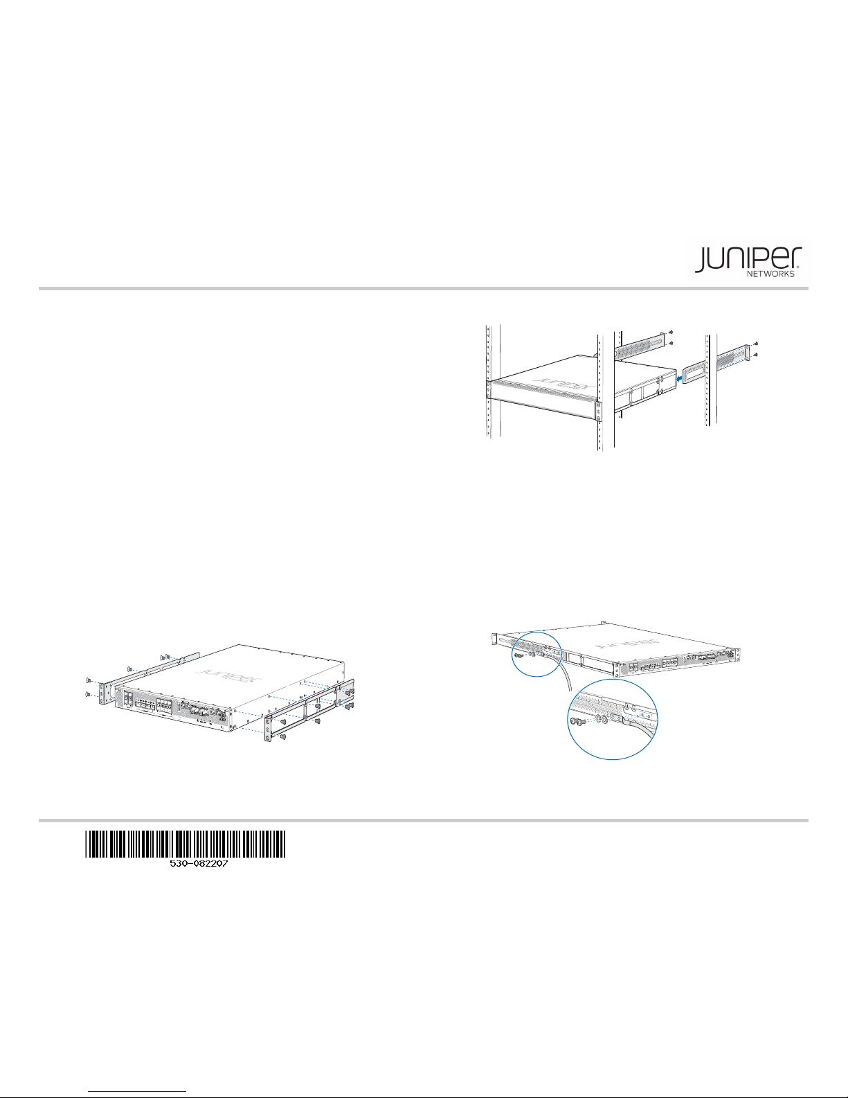
Part 1: Mount the Services Gateway
You can mount an SRX4600 Services Gateway in a 19-inch four-post rack configuration.
An AC device weighs approximately 38 lb (17.23 kg) and a DC device weighs
approximately 40 lb (18.14 kg). Two persons are required for mounting the device.
1. Attach the ESD grounding strap to your bare wrist and to a site ESD point.
NOTE: If you are mounting multiple units in the rack, mount the heaviest unit at the
bottom and mount the others from bottom to top in order of decreasing weight.
2. Place the rack in its permanent location, allowing adequate clearance for airflow and
maintenance, and secure it to the building structure.
3. Attach the front-mounting brackets to the side mounting rails by using the Phillips
4-40 flat-head mounting screws.
4. Align the holes in the side mounting rails with the holes on the side of the chassis and
attach the side mounting rails to the chassis by using the mounting screws.
5. Have one person grasp both sides of the device, lift it, and position it in the rack so
that the front bracket is aligned with the rack holes and the second person secure the
front of the device to the rack by using four mounting screws.
6. Have the second person use the mounting screws (and cage nuts and washers if
your rack requires them) to screw the mounting bracket to the rack.
7. Continue to support the device and slide the rear mounting blades into the channel of
the side mounting rails and securing the blades to the rack. Use the four mounting
screws (cage nuts and washers if the rack requires) to attach each blade to the rack.
8. Attach a grounding cable to earth ground and then to the chassis grounding points.
Part 2: Connect the Grounding Cable
1. Attach an ESD grounding strap to your bare wrist, and connect the strap to the ESD
point on the chassis.
2. Connect one end of the grounding cable to a proper earth ground, such as the rack in
which the services gateway is mounted.
3. Place the grounding lug attached to the grounding cable over the protective earthing
terminal on the protective earthing terminal bracket.
4. Secure the grounding lug to the protective earthing terminal with the washers and
screws.
5. Dress the grounding cable and ensure that it does not touch or block access to other
device components and that it does not drape where people could trip over it.
g009541
g009539
g009510
Page 2
Juniper Networks, Junos, Steel-Belted Radius, NetScreen, and ScreenOS are registered trademarks of Juniper Networks, Inc. in the United States and other countries. The Juniper Networks Logo, the Junos logo, and JunosE are
trademarks of Juniper Networks, Inc. All other trademarks, service marks, registered trademarks, or registered service marks are the property of their respective owners. Junip er Networks assumes no responsibility for any inaccuracies
in this document. Juniper Networks reserves the right to change, modify, transfer, or otherwise revise this publication without notice. Products made or sold by Juniper Netw orks or components thereof might be covered by one or more
of the following patents that are owned by or licensed to Juniper Networks: U.S. Patent Nos. 5,473,599, 5,905,725, 5,909,440, 6,192,051, 6,333,650, 6,359,479, 6,406,312, 6,429, 706, 6,459,579, 6,493,347, 6,538,518, 6,538,899,
6,552,918, 6,567,902, 6,578,186, and 6,590,785. Copyright © 2016, Juniper Networks, Inc. All rights reserved. Part Number: 530-082207, Revision 01, December 2017
Part 3: Connect Power to the Device
NOTE: Check if the power supplies AC or DC are fully inserted into the chassis.
If you are using the AC model, perform the following steps:
NOTE: An AC-powered device gets additional grounding when you connect the power
supply in the device to a grounded AC power outlet by using the power cord.
1. Insert the coupler end of the power cord into the AC power cord inlet on the AC
power supply faceplate. Push the power cord retainer onto the power cord.
2. Insert the power cord plug into an AC power source outlet:
− If the AC power source outlet has a power switch, set it to on (|) position and the
services gateway will power on.
− If there is no power switch on the AC power source outlet, the services gateway
will power on instantly.
3. Verify that the OK/FAIL LED is lit green and on steadily.
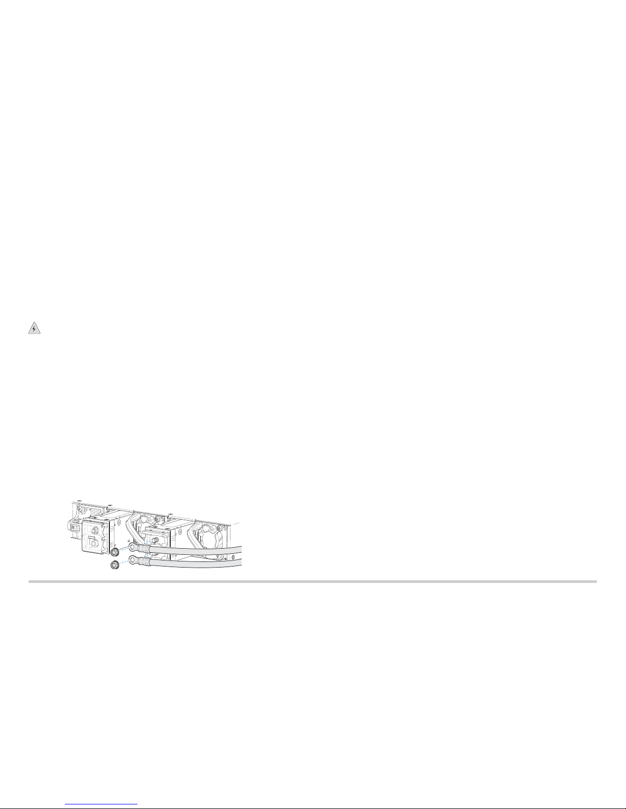
If you are using the DC model, perform the following steps:
WARNING: Before performing the following procedure, ensure that there is no
power in the DC circuit. To ensure that all power is cut off, locate the circuit breaker
on the panel board that services the DC circuit, switch the circuit breaker to the off
(0) position, and tape the switch handle of the circuit breaker in the off position.
1. Ensure that the voltage across the DC power source cable leads is 0 V and that the
cable leads do not become active while you are connecting DC power.
2. Verify that the DC power cables are correctly labeled before connecting them to the
power supply. In a typical power distribution scheme where the return is connected to
chassis ground at the battery plant, you can use a multimeter to verify the resistance
of the –48V and RTN DC cables to chassis ground:
− The cable with very high resistance (indicating an open circuit) to chassis ground
is negative (–) and is installed on the –48V (input) DC power input terminal.
− The cable with very low resistance (indicating a closed circuit) to chassis ground is
positive (+) and is installed on the RTN (return) DC power input terminal.
3. Remove the protective cover from the DC power input terminal block. Save this cover
for future use.
4. Remove the M5 K-nuts from each DC power input terminal.
5. Attach DC terminal rings (TYCO 2-36161-2 Terminal Ring, number 10, not provided)
to the ends of the DC power cables. Crimp tightly.
6. Insert the DC terminal rings into the DC power input terminals and secure the DC
terminal rings with M5 K-nuts. Do not overtighten.
7. Replace the protective cover over the input terminal block.
8. Remove the tape from the switch handle of the circuit breaker on the panel board that
services the DC circuit, and switch the circuit breaker to the ON (|) position.
9. Verify that the OK/FAIL LED is lit green and on steadily.
Part 4: Perform Initial Configuration
You must perform the initial configuration of the device through the console port. Before
you begin, set the following parameter values in the console server or the management
host: baud rate—9600; flow control—none; data—8; parity—none; stop bits—1; DCD
state—disregard
To configure the device from the console:
1. Connect the console port (CON), located on the front panel of the services gateway
to a laptop or PC by using the provided RJ-45 cable and RJ-45 to DB-9 serial port
adapter.
2. Log in as the root user. There is no password.
login: root
3. Start the CLI:
root#cli
root@>
4. Enter configuration mode:
root@> configure
Entering configuration mode
[edit]
root@#
5. Set the root authentication password by entering either a cleartext password, an
encrypted password, or an SSH public key string (DSA or RSA):
[edit]
root@#set system root-authentication plain-text-password
New password: password
Retype new password: password
6. Configure an administrator account on the device. When prompted, enter the
password for the administrator account:
[edit]
root@#set system login user admin class super-user
authentication plain-text-password
New password: password
Retype new password: password
7. Commit the configuration to activate it on the device:
[edit]
root@# commit
8. Log in as the administrative user you configured in Step 6.
g009524
Page 3

SRX4600 Services Gateway Quick Start
9. (Optional) Configure the name of the device. If the name includes spaces, enclose
the name in quotation marks (“ ”):
[edit]
admin@# set system host-name host-name
10. Configure the IP address and prefix length for the management interface on the
device:
[edit]
admin@# set interfaces fxp0 unit 0 family inet address
address/prefix-length
11. Configure the default route:
[edit]
admin@# set routing-options static route 0.0.0.0/0 next-hop
gateway
12. Check the configuration for validity:
[edit]
admin@# commit check
13. Commit the configuration to activate it on the device:
[edit]
admin@# commit
Safety Warnings Summary
This is a summary of safety warnings. For a complete list of warnings, including
translations, see the SRX4600 Services Gateway documentation at
https://www.juniper.net/techpubs/a077.html .
WARNING: Failure to observe these safety warnings can result in personal injury
or death.
z Permit only trained and qualified personnel to install or replace device components.
z Perform only the procedures described in this quick start and the SRX4600 Services
Gateway documentation. Other services must be performed only by authorized service
personnel.
z Before installing the device, read the planning instructions in the SRX4600 Services
Gateway documentation to make sure that the site meets power, environmental, and
clearance requirements for the device.
z Before connecting the device to a power source, read the installation instructions in the
SRX4600 Services Gateway documentation.
z The services gateway weighs approximately 22 lb (9.97 kg). Manually installing the
device in a rack at a height above 60 in. (152.4 cm) requires two persons; one to lift the
device and the second to install the mounting screws. To prevent injury while lifting,
keep your back straight and lift with your legs, not your back.
z If the rack has stabilizing devices, install them in the rack before mounting or servicing
the device in the rack.
z Before installing or after removing an electrical component, always place it
component-side up on an antistatic mat placed on a flat, stable surface or in an
antistatic bag.
z Do not work on the device or connect or disconnect cables during electrical storms.
z Before working on equipment that is connected to power lines, remove jewelry,
including rings, necklaces, and watches. Metal objects heat up when connected to
power and ground and can cause serious burns or become welded to the terminals.
Power Cable Warning (Japanese)
The attached power cable is only for this product. Do not use this cable for another
product.
Contacting Juniper Networks
For technical support, see http://www.juniper.net/support/requesting-support.html .
g017253
 Loading...