

Page 1

SRX3400 Services Gateway
Hardware Guide
Published: 2013-12-30
Copyright © 2013, Juniper Networks, Inc.
Page 2

Juniper Networks, Inc.
1194 North Mathilda Avenue
Sunnyvale, California 94089
USA
408-745-2000
www.juniper.net
Juniper Networks, Junos, Steel-Belted Radius, NetScreen, and ScreenOS are registered trademarks of Juniper Networks, Inc. in the United
States and other countries. The Juniper Networks Logo, the Junos logo, and JunosE are trademarks of Juniper Networks, Inc. All other
trademarks, service marks, registered trademarks, or registered service marks are the property of their respective owners.
Juniper Networks assumes no responsibility for any inaccuracies in this document. Juniper Networks reserves the right to change, modify,
transfer, or otherwise revise this publication without notice.
SRX3400 Services Gateway Hardware Guide
Copyright © 2013, Juniper Networks, Inc.
All rights reserved. Printed in USA.
Revision History
August 2012—Revision 08
December 2012—Revision 09 Added NP-IOC, moved CFM and module content into SRX1400, SRX3400, and SRX3600 Services Gateway
Module Guide
June 2013—Revision 10 Incorporated additional warnings that the chassis must be connected to earth ground
December 2013—Revision 11 Minor revisions.
The information in this document is current as of the date on the title page.
SOFTWARE LICENSE
The terms and conditions for using this software are described in the software license contained in the acknowledgment to your purchase
order or, to the extent applicable, to any reseller agreement or end-user purchase agreement executed between you and Juniper Networks.
By using this software, you indicate that you understand and agree to be bound by those terms and conditions.
Generally speaking, the software license restricts the manner in which you are permitted to use the software and may contain prohibitions
against certain uses. The software license may state conditions under which the license is automatically terminated. You should consult
the license for further details.
For complete product documentation, please see the Juniper Networks Web site at www.juniper.net/techpubs.
END USER LICENSE AGREEMENT
The Juniper Networks product that is the subject of this technical documentation consists of (or is intended for use with) Juniper Networks
software. Use of such software is subject to the terms and conditions of the End User License Agreement (“EULA”) posted at
http://www.juniper.net/support/eula.html. By downloading, installing or using such software, you agree to the terms and conditions of
that EULA.
Copyright © 2013, Juniper Networks, Inc.ii
Page 3

Table of Contents
About This Guide . . . . . . . . . . . . . . . . . . . . . . . . . . . . . . . . . . . . . . . . . . . . . . . . . . ix
Objectives . . . . . . . . . . . . . . . . . . . . . . . . . . . . . . . . . . . . . . . . . . . . . . . . . . . . . . ix
Audience . . . . . . . . . . . . . . . . . . . . . . . . . . . . . . . . . . . . . . . . . . . . . . . . . . . . . . . ix
Documentation Conventions . . . . . . . . . . . . . . . . . . . . . . . . . . . . . . . . . . . . . . . ix
SRX Series Documentation and Release Notes . . . . . . . . . . . . . . . . . . . . . . . . xi
Obtaining Documentation . . . . . . . . . . . . . . . . . . . . . . . . . . . . . . . . . . . . . . . . . xi
Documentation Feedback . . . . . . . . . . . . . . . . . . . . . . . . . . . . . . . . . . . . . . . . . xii
Requesting Technical Support . . . . . . . . . . . . . . . . . . . . . . . . . . . . . . . . . . . . . xii
Part 1 SRX3400 Services Gateway Overview
Chapter 1 Introduction to the SRX3400 Services Gateway . . . . . . . . . . . . . . . . . . . . . . . 3
SRX3400 Services Gateway Description . . . . . . . . . . . . . . . . . . . . . . . . . . . . . . . . . 3
SRX3400 Services Gateway Performance and Features . . . . . . . . . . . . . . . . . . . . . 4
SRX3400 Services Gateway Physical Specifications . . . . . . . . . . . . . . . . . . . . . . . . 4
Chapter 2 SRX3400 Services Gateway Hardware Components . . . . . . . . . . . . . . . . . . . 7
SRX3400 Services Gateway Chassis . . . . . . . . . . . . . . . . . . . . . . . . . . . . . . . . . . . . . 7
SRX3400 Services Gateway Component Basics . . . . . . . . . . . . . . . . . . . . . . . . . . . 9
SRX3400 Services Gateway CFMs . . . . . . . . . . . . . . . . . . . . . . . . . . . . . . . . . . 9
Available Components for the SRX3400 Services Gateway . . . . . . . . . . . . . . 9
Hardware Component Locations in the SRX3400 Services Gateway
Chassis . . . . . . . . . . . . . . . . . . . . . . . . . . . . . . . . . . . . . . . . . . . . . . . . . . . . . 11
Data Flow in the SRX3400 Services Gateway . . . . . . . . . . . . . . . . . . . . . . . . . 13
SRX3400 Services Gateway Midplane . . . . . . . . . . . . . . . . . . . . . . . . . . . . . . . . . . 13
SRX3400 Services Gateway Switch Fabric Board . . . . . . . . . . . . . . . . . . . . . . . . . 14
SRX3400 Services Gateway NPCs . . . . . . . . . . . . . . . . . . . . . . . . . . . . . . . . . . . . . 20
SRX3400 Services Gateway SPCs . . . . . . . . . . . . . . . . . . . . . . . . . . . . . . . . . . . . . 20
SRX3400 Services Gateway IOCs . . . . . . . . . . . . . . . . . . . . . . . . . . . . . . . . . . . . . . 21
SRX3400 Services Gateway NP-IOCs . . . . . . . . . . . . . . . . . . . . . . . . . . . . . . . . . . . 22
SRX3400 Services Gateway Routing Engine . . . . . . . . . . . . . . . . . . . . . . . . . . . . . 23
SRX3400 Services Gateway SRX Clustering Module . . . . . . . . . . . . . . . . . . . . . . . 24
SRX3400 Services Gateway Power Supplies . . . . . . . . . . . . . . . . . . . . . . . . . . . . . 25
SRX3400 Services Gateway AC Power Supply Overview . . . . . . . . . . . . . . . . 25
SRX3400 Services Gateway AC Power Supply Electrical Specifications . . . . 26
SRX3400 Services Gateway DC Power Supply Overview . . . . . . . . . . . . . . . . 27
SRX3400 Services Gateway DC Power Supply Electrical Specifications . . . 28
SRX3400 Services Gateway Fan Tray . . . . . . . . . . . . . . . . . . . . . . . . . . . . . . . . . . . 29
SRX3400 and SRX5600 Services Gateways Air Deflector Kits . . . . . . . . . . . . . . . 31
iiiCopyright © 2013, Juniper Networks, Inc.
Page 4

SRX3400 Services Gateway Hardware Guide
Part 2 Setting Up the SRX3400 Services Gateway
Chapter 3 Preparing the Site for SRX3400 Services Gateway Installation . . . . . . . . . 37
Site Preparation Checklist for the SRX3400 Services Gateway . . . . . . . . . . . . . . . 37
SRX3400 Services Gateway Cabinet Requirements . . . . . . . . . . . . . . . . . . . . . . . 38
SRX3400 Services Gateway Cabinet Size and Clearance Requirements . . . 38
SRX3400 Services Gateway Cabinet Airflow Requirements . . . . . . . . . . . . . 39
SRX3400 Services Gateway Rack Requirements . . . . . . . . . . . . . . . . . . . . . . . . . 39
SRX3400 Services Gateway Rack Size and Strength Requirements . . . . . . . 40
SRX3400 Services Gateway Spacing of Mounting Bracket Holes . . . . . . . . . 41
Connecting the SRX3400 Services Gateway to the Building Structure . . . . . 42
Clearance Requirements for Airflow and Hardware Maintenance ofthe SRX3400
Services Gateway . . . . . . . . . . . . . . . . . . . . . . . . . . . . . . . . . . . . . . . . . . . . . . . 42
Chapter 4 Unpacking the SRX3400 Services Gateway . . . . . . . . . . . . . . . . . . . . . . . . . . 45
Required Tools and Parts for Unpacking the SRX3400 Services Gateway . . . . . . 45
Unpacking the SRX3400 Services Gateway . . . . . . . . . . . . . . . . . . . . . . . . . . . . . . 45
Verifying Parts Received with the SRX3400 Services Gateway . . . . . . . . . . . . . . . 47
Chapter 5 Installing the SRX3400 Services Gateway . . . . . . . . . . . . . . . . . . . . . . . . . . . 49
Installation Overview for the SRX3400 Services Gateway . . . . . . . . . . . . . . . . . . 49
SRX3400 Services Gateway Safety Requirements, Warnings, and Guidelines . . 50
Required Tools for Installing the SRX3400 Services Gateway . . . . . . . . . . . . . . . 50
Preparing the SRX3400 Services Gateway for Rack-Mount or Cabinet
Installation . . . . . . . . . . . . . . . . . . . . . . . . . . . . . . . . . . . . . . . . . . . . . . . . . . . . . 51
Installing the Mounting Hardware for the SRX3400 Services Gateway . . . . . . . . . 51
Installing the SRX3400 Services Gateway in a Rack or Cabinet Using a
Mechanical Lift . . . . . . . . . . . . . . . . . . . . . . . . . . . . . . . . . . . . . . . . . . . . . . . . . 53
Installing the SRX3400 Services Gateway in a Rack or Cabinet Without a
Mechanical Lift . . . . . . . . . . . . . . . . . . . . . . . . . . . . . . . . . . . . . . . . . . . . . . . . . 55
Required Tools for Installing the SRX3400 Services Gateway Without a
RemovingComponents from theChassis for ManualLifting of the SRX3400
Lifting the SRX3400 Services Gateway Chassis into the Rack . . . . . . . . . . . . 57
Reinstalling Components in the SRX3400 Services Gateway Chassis . . . . . 58
Chapter 6 Installing Additional Components in the SRX3400 Services Gateway . . . 59
Installing CFM Cards in the SRX3400 Services Gateway . . . . . . . . . . . . . . . . . . . 59
Installing SPCs in an Operating SRX3400 Services Gateway Chassis Cluster . . . 62
Installing an SCM in the SRX3400 Services Gateway . . . . . . . . . . . . . . . . . . . . . . 65
Installing an AC Power Supply in the SRX3400 Services Gateway . . . . . . . . . . . . 66
Installing a DC Power Supply in the SRX3400 Services Gateway . . . . . . . . . . . . . 69
Chapter 7 Connecting the SRX3400 Services Gateway . . . . . . . . . . . . . . . . . . . . . . . . . . 71
Required Tools and Parts for Connecting the SRX3400 Services Gateway . . . . . . 71
Connecting the SRX3400 Services Gateway to Management Devices . . . . . . . . . 71
Connecting the SRX3400 Services Gateway to a Network for Out-of-Band
Connecting the SRX3400 Services Gateway to a Management Console or
Mechanical Lift . . . . . . . . . . . . . . . . . . . . . . . . . . . . . . . . . . . . . . . . . . . . . 55
Services Gateway . . . . . . . . . . . . . . . . . . . . . . . . . . . . . . . . . . . . . . . . . . . 55
Management . . . . . . . . . . . . . . . . . . . . . . . . . . . . . . . . . . . . . . . . . . . . . . . 72
an Auxiliary Device . . . . . . . . . . . . . . . . . . . . . . . . . . . . . . . . . . . . . . . . . . . 72
Copyright © 2013, Juniper Networks, Inc.iv
Page 5

Table of Contents
Chapter 8 Grounding and Providing Power to the SRX3400 Services Gateway . . . . . 75
Required Tools and Parts for Grounding and Providing Power to the SRX3400
Services Gateway . . . . . . . . . . . . . . . . . . . . . . . . . . . . . . . . . . . . . . . . . . . . . . . 75
Grounding the SRX3400 Services Gateway . . . . . . . . . . . . . . . . . . . . . . . . . . . . . . 76
Connecting the SRX3400 Services Gateway to an AC Power Source . . . . . . . . . . 77
Connecting the SRX3400 Services Gateway to a DC Power Source . . . . . . . . . . . 79
Powering On the SRX3400 Services Gateway . . . . . . . . . . . . . . . . . . . . . . . . . . . . 81
Powering Off the SRX3400 Services Gateway . . . . . . . . . . . . . . . . . . . . . . . . . . . . 82
Chapter 9 Performing Initial Software Configuration on the SRX3400 Services
Gateway . . . . . . . . . . . . . . . . . . . . . . . . . . . . . . . . . . . . . . . . . . . . . . . . . . . . . . . . . 85
SRX3400 Services Gateway Software Configuration Overview . . . . . . . . . . . . . . 85
Performing Initial Software Configuration on the SRX3400 Services
Gateway . . . . . . . . . . . . . . . . . . . . . . . . . . . . . . . . . . . . . . . . . . . . . . . . . . . . . . 86
Part 3 SRX3400 Services Gateway Hardware Maintenance,
Replacement, and Troubleshooting Procedures
Chapter 10 Maintaining the SRX3400 Services Gateway Hardware Components . . . 93
Required Tools and Parts for Maintaining the SRX3400 Services Gateway
Hardware Components . . . . . . . . . . . . . . . . . . . . . . . . . . . . . . . . . . . . . . . . . . 93
Routine Maintenance Procedures for the SRX3400 Services Gateway . . . . . . . . 94
Maintaining the Air Filter on the SRX3400 Services Gateway . . . . . . . . . . . . . . . . 94
Maintaining the Fan Tray on the SRX3400 Services Gateway . . . . . . . . . . . . . . . . 95
Maintaining the Routing Engine on the SRX3400 Services Gateway . . . . . . . . . . 96
Maintaining the Power Supplies on the SRX3400 Services Gateway . . . . . . . . . . 97
Chapter 11 Troubleshooting the SRX3400 Services Gateway . . . . . . . . . . . . . . . . . . . . . 99
Troubleshooting Hardware Components on the SRX3400 Services Gateway . . 99
Troubleshooting with the CLI on the SRX3400 Services Gateway . . . . . . . . 99
Troubleshooting with LEDs on the SRX3400 Services Gateway . . . . . . . . . 100
Troubleshooting with Chassis and Interface Alarm Messages on the
SRX3400 Services Gateway . . . . . . . . . . . . . . . . . . . . . . . . . . . . . . . . . . 101
Juniper Networks Technical Assistance Center . . . . . . . . . . . . . . . . . . . . . . . . 101
Troubleshooting the Cooling System on the SRX3400 Services Gateway . . . . . . 101
Troubleshooting IOCs and NP-IOCs on the SRX3400 Services Gateway . . . . . . 102
Troubleshooting NPCs on the SRX3400 Services Gateway . . . . . . . . . . . . . . . . . 104
Troubleshooting SPCs on the SRX3400 Services Gateway . . . . . . . . . . . . . . . . . 105
Troubleshooting the Power System on the SRX3400 Services Gateway . . . . . . 106
Chapter 12 Replacing Hardware Components on the SRX3400 Services Gateway . . 109
Field-Replaceable Units on the SRX3400 Services Gateway . . . . . . . . . . . . . . . 109
RequiredTools and Parts for Replacing Hardware Components onthe SRX3400
Services Gateway . . . . . . . . . . . . . . . . . . . . . . . . . . . . . . . . . . . . . . . . . . . . . . . 110
Replacing Cooling System Components on the SRX3400 Services Gateway . . . 111
Replacing the Fan Tray on the SRX3400 Services Gateway . . . . . . . . . . . . . 112
Replacing the Air Filter on the SRX3400 Services Gateway . . . . . . . . . . . . . . 114
Replacing Host Subsystem Components on the SRX3400 Services Gateway . . 115
Replacing the SFB on the SRX3400 Services Gateway . . . . . . . . . . . . . . . . . 116
Replacing a Routing Engine on the SRX3400 Services Gateway . . . . . . . . . . 118
vCopyright © 2013, Juniper Networks, Inc.
Page 6

SRX3400 Services Gateway Hardware Guide
Replacing an SCM on the SRX3400 Services Gateway . . . . . . . . . . . . . . . . . 120
Replacing a CFM Card on the SRX3400 Services Gateway . . . . . . . . . . . . . . 121
Replacing SFP, SFP+, and XFP Transceivers on the SRX3400 Services
Replacing Power System Components on the SRX3400 Services Gateway . . . . 127
Replacing an AC Power Supply on the SRX3400 Services Gateway . . . . . . 128
Replacing AC Power Supply Cables on the SRX3400 Services Gateway . . . 130
Replacing a DC Power Supply on the SRX3400 Services Gateway . . . . . . . 132
Replacing DC Power Supply Cables on the SRX3400 Services Gateway . . . 135
Part 4 Appendixes
Appendix A Safety and Regulatory Compliance Information . . . . . . . . . . . . . . . . . . . . . . 139
SRX3400 Services Gateway Definition of Safety Warning Levels . . . . . . . . . . . . 139
SRX3400 Services Gateway General Safety Guidelines and Warnings . . . . . . . . 141
Additional SRX3400 Services Gateway Warnings . . . . . . . . . . . . . . . . . . . . . . . . 142
Qualified Personnel Warning . . . . . . . . . . . . . . . . . . . . . . . . . . . . . . . . . . . . . . 142
Restricted Access Area Warning . . . . . . . . . . . . . . . . . . . . . . . . . . . . . . . . . . . 143
Preventing Electrostatic Discharge Damage to the SRX3400 Services
Gateway . . . . . . . . . . . . . . . . . . . . . . . . . . . . . . . . . . . . . . . . . . . . . . . . . . . . . . 145
SRX3400 Services Gateway Fire Safety Requirements and Fire Suppression
Equipment . . . . . . . . . . . . . . . . . . . . . . . . . . . . . . . . . . . . . . . . . . . . . . . . . . . . 146
SRX3400 Services Gateway Installation Safety Guidelines and Warnings . . . . . 148
Chassis Lifting Guidelines . . . . . . . . . . . . . . . . . . . . . . . . . . . . . . . . . . . . . . . . 148
Installation Instructions Warning . . . . . . . . . . . . . . . . . . . . . . . . . . . . . . . . . . 148
Rack-Mounting Requirements and Warnings . . . . . . . . . . . . . . . . . . . . . . . . 149
Ramp Warning . . . . . . . . . . . . . . . . . . . . . . . . . . . . . . . . . . . . . . . . . . . . . . . . . 153
SRX3400 Services Gateway Laser and LED Safety Guidelines and Warnings . . 153
General Laser Safety Guidelines . . . . . . . . . . . . . . . . . . . . . . . . . . . . . . . . . . . 154
Class 1 Laser Product Warning . . . . . . . . . . . . . . . . . . . . . . . . . . . . . . . . . . . . 154
Class 1 LED Product Warning . . . . . . . . . . . . . . . . . . . . . . . . . . . . . . . . . . . . . . 155
Laser Beam Warning . . . . . . . . . . . . . . . . . . . . . . . . . . . . . . . . . . . . . . . . . . . . 155
Radiation from Open Port Apertures Warning . . . . . . . . . . . . . . . . . . . . . . . . 156
SRX3400 Services Gateway Maintenance and Operational Safety Guidelines
and Warnings . . . . . . . . . . . . . . . . . . . . . . . . . . . . . . . . . . . . . . . . . . . . . . . . . . 157
Battery Handling Warning . . . . . . . . . . . . . . . . . . . . . . . . . . . . . . . . . . . . . . . . 157
Jewelry Removal Warning . . . . . . . . . . . . . . . . . . . . . . . . . . . . . . . . . . . . . . . . 158
Lightning Activity Warning . . . . . . . . . . . . . . . . . . . . . . . . . . . . . . . . . . . . . . . 160
Operating Temperature Warning . . . . . . . . . . . . . . . . . . . . . . . . . . . . . . . . . . . 161
Product Disposal Warning . . . . . . . . . . . . . . . . . . . . . . . . . . . . . . . . . . . . . . . . 162
SRX3400 Services Gateway Electrical Safety Guidelines and Warnings . . . . . . . 163
In Case of Electrical Accident . . . . . . . . . . . . . . . . . . . . . . . . . . . . . . . . . . . . . 163
General Electrical Safety Guidelines and Warnings . . . . . . . . . . . . . . . . . . . . 163
DC Power Electrical Safety Guidelines and Warnings . . . . . . . . . . . . . . . . . . 168
SRX3400 Services Gateway Agency Approvals . . . . . . . . . . . . . . . . . . . . . . . . . . 174
SRX3400 Services Gateway Compliance Statements for EMC Requirements . . 175
Canada . . . . . . . . . . . . . . . . . . . . . . . . . . . . . . . . . . . . . . . . . . . . . . . . . . . . . . . 175
European Community . . . . . . . . . . . . . . . . . . . . . . . . . . . . . . . . . . . . . . . . . . . 175
Japan . . . . . . . . . . . . . . . . . . . . . . . . . . . . . . . . . . . . . . . . . . . . . . . . . . . . . . . . 175
Gateway . . . . . . . . . . . . . . . . . . . . . . . . . . . . . . . . . . . . . . . . . . . . . . . . . . 124
Copyright © 2013, Juniper Networks, Inc.vi
Page 7

Table of Contents
United States . . . . . . . . . . . . . . . . . . . . . . . . . . . . . . . . . . . . . . . . . . . . . . . . . . 175
SRX3400 Services Gateway NEBS and ETSI Compliance . . . . . . . . . . . . . . . . . . 176
SRX3400 Services Gateway NEBS and ETSI Standards . . . . . . . . . . . . . . . . 176
SRX3400 Services Gateway NEBS and ETSI Configuration
Requirements . . . . . . . . . . . . . . . . . . . . . . . . . . . . . . . . . . . . . . . . . . . . . . 176
Appendix B SRX3400 Services Gateway Environmental Specifications . . . . . . . . . . . . 179
SRX3400 Services Gateway Environmental Specifications . . . . . . . . . . . . . . . . . 179
Appendix C SRX3400 Services Gateway Power Guidelines, Requirements, and
Specifications . . . . . . . . . . . . . . . . . . . . . . . . . . . . . . . . . . . . . . . . . . . . . . . . . . . . 181
SRX3400 Services Gateway Grounding Specifications . . . . . . . . . . . . . . . . . . . . . 181
SRX3400 Services Gateway Chassis Grounding Point . . . . . . . . . . . . . . . . . . 181
SRX3400 Services Gateway Grounding-Cable Lug Specification . . . . . . . . 182
SRX3400 Services Gateway Grounding Cable Specification . . . . . . . . . . . . 183
SRX3400 Services Gateway DC Power Specifications and Requirements . . . . . 183
SRX3400 Services Gateway DC Power System Electrical Specifications . . 183
SRX3400 Services Gateway DC Power Supply Electrical Specifications . . . 184
Power Requirements for DC-Powered SRX3400 Services Gateways . . . . . 184
SRX3400 Services Gateway DC Power Cable Specifications . . . . . . . . . . . . 186
SRX3400 Services Gateway AC Power Specifications and Requirements . . . . . 188
SRX3400 Services Gateway AC Power System Electrical Specifications . . 188
SRX3400 Services Gateway AC Power Supply Electrical Specifications . . . 188
Power Requirements for AC-Powered SRX3400 Services Gateways . . . . . 189
SRX3400 Services Gateway AC Power Cord Specifications . . . . . . . . . . . . . 191
Appendix D Cable and Wire Guidelines for the SRX3400 Services Gateway
Hardware . . . . . . . . . . . . . . . . . . . . . . . . . . . . . . . . . . . . . . . . . . . . . . . . . . . . . . . 195
SRX3400 Services Gateway Electrical Wiring Guidelines . . . . . . . . . . . . . . . . . . 195
Distance Limitations for Signaling for the SRX3400 Services Gateway . . . . 195
Radio Frequency Interference for the SRX3400 Services Gateway . . . . . . . 195
Electromagnetic Compatibility for the SRX3400 Services Gateway . . . . . . 196
SRX3400 Services Gateway Network Cable Guidelines . . . . . . . . . . . . . . . . . . . 196
Signal Loss in Multimode and Single-Mode Fiber-Optic Cable for the
SRX3400 Services Gateway . . . . . . . . . . . . . . . . . . . . . . . . . . . . . . . . . . 196
Attenuation and Dispersion in Fiber-Optic Cable for the SRX3400 Services
Gateway . . . . . . . . . . . . . . . . . . . . . . . . . . . . . . . . . . . . . . . . . . . . . . . . . . 197
Calculating the Power Budget for Fiber-Optic Cable for the SRX3400
Services Gateway . . . . . . . . . . . . . . . . . . . . . . . . . . . . . . . . . . . . . . . . . . . 198
Calculating the Power Margin for Fiber-Optic Cable for the SRX3400
Services Gateway . . . . . . . . . . . . . . . . . . . . . . . . . . . . . . . . . . . . . . . . . . . 198
Console Port Cable and Wire Specifications for the SRX3400 Services
Gateway . . . . . . . . . . . . . . . . . . . . . . . . . . . . . . . . . . . . . . . . . . . . . . . . . . . . . 200
Appendix E Contacting Customer Support and Returning the SRX3400 Services
Gateway Hardware . . . . . . . . . . . . . . . . . . . . . . . . . . . . . . . . . . . . . . . . . . . . . . . 201
Return Procedure for the SRX3400 Services Gateway . . . . . . . . . . . . . . . . . . . . . 201
Locating SRX3400 Services Gateway Component Serial Numbers . . . . . . . . . . 202
Listing the SRX3400 Services Gateway Component Serial Numbers with
the CLI . . . . . . . . . . . . . . . . . . . . . . . . . . . . . . . . . . . . . . . . . . . . . . . . . . . 202
Locating the SRX3400 Services Gateway Chassis Serial Number Label . . 203
viiCopyright © 2013, Juniper Networks, Inc.
Page 8

SRX3400 Services Gateway Hardware Guide
Locating the SRX3400 Services Gateway SFB Serial Number Label . . . . . 204
Locating the SRX3400 Services Gateway Power-Supply Serial Number
Contacting Customer Support to Obtain Return Materials Authorization for the
SRX3400 Services Gateway . . . . . . . . . . . . . . . . . . . . . . . . . . . . . . . . . . . . . 204
Information You Might Need to Supply to JTAC . . . . . . . . . . . . . . . . . . . . . . . 205
Contacting Customer Support . . . . . . . . . . . . . . . . . . . . . . . . . . . . . . . . . . . . 205
Packing an SRX3400 Services Gateway or a Component for Shipment . . . . . . 205
Required Tools and Parts for Packing the SRX3400 Services Gateway . . . 206
Packing the SRX3400 Services Gateway for Shipment . . . . . . . . . . . . . . . . 206
Packing SRX3400 Services Gateway Components for Shipment . . . . . . . . 207
Appendix F Product Recycling . . . . . . . . . . . . . . . . . . . . . . . . . . . . . . . . . . . . . . . . . . . . . . . 209
Removingthe Battery fromthe Routing Engineof anSRX3400 Services Gateway
for Recycling . . . . . . . . . . . . . . . . . . . . . . . . . . . . . . . . . . . . . . . . . . . . . . . . . . 209
Part 5 Index
Index . . . . . . . . . . . . . . . . . . . . . . . . . . . . . . . . . . . . . . . . . . . . . . . . . . . . . . . . . . . . 213
Label . . . . . . . . . . . . . . . . . . . . . . . . . . . . . . . . . . . . . . . . . . . . . . . . . . . . 204
Copyright © 2013, Juniper Networks, Inc.viii
Page 9

About This Guide
•
Objectives on page ix
•
Audience on page ix
•
Documentation Conventions on page ix
•
SRX Series Documentation and Release Notes on page xi
•
Obtaining Documentation on page xi
•
Documentation Feedback on page xii
•
Requesting Technical Support on page xii
Objectives
This guide describes hardware components and installation, basic configuration, and
basic troubleshooting procedures for the Juniper Networks SRX3400 Services Gateway.
It explains how to prepare your site for services gateway installation, unpack and install
the hardware, power on the services gateway, perform initial software configuration, and
perform routine maintenance. After completing the installation and basic configuration
procedures covered in this guide, see the Junos OS configuration guides for information
about further Junos OS configuration.
Audience
This guide is designed for network administrators who are installing and maintaining a
Juniper Networks SRX3400 Services Gateway or preparing a site for services gateway
installation. To use this guide, you need a broad understanding of networks in general
and the Internet in particular, networking principles, and network configuration. Any
detailed discussion of these concepts is beyond the scope of this guide.
Documentation Conventions
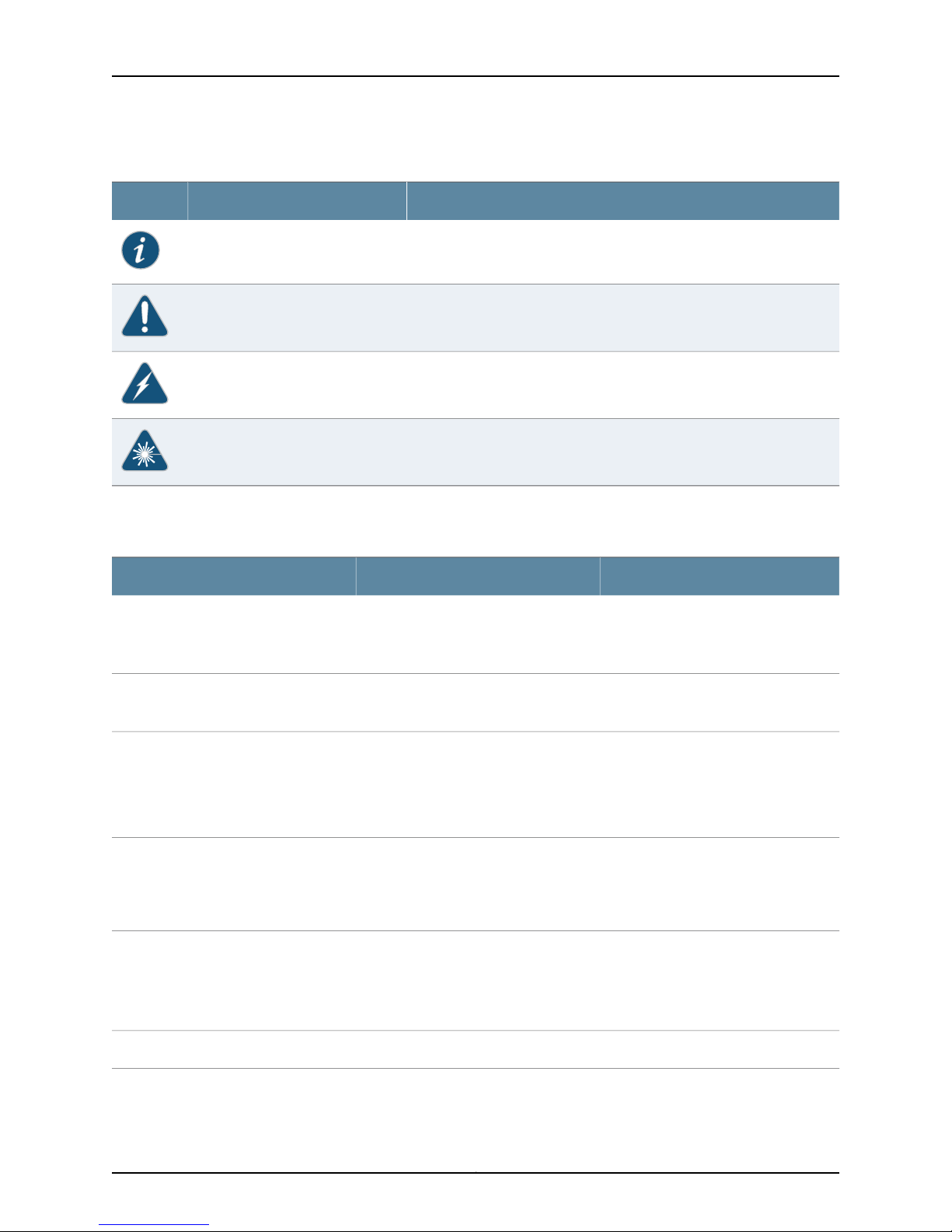
Table 1 on page x defines the notice icons used in this guide.
ixCopyright © 2013, Juniper Networks, Inc.
Page 10
SRX3400 Services Gateway Hardware Guide
Table 1: Notice Icons
Table 2 on page x defines the text and syntax conventions used in this guide.
DescriptionMeaningIcon
Indicates important features or instructions.Informational note
Indicates a situation that might result in loss of data or hardware damage.Caution
Alerts you to the risk of personal injury or death.Warning
Alerts you to the risk of personal injury from a laser.Laser warning
Table 2: Text and Syntax Conventions
Represents text that you type.Bold text like this
Fixed-width text like this
Italic text like this
Italic text like this
Text like this
Represents output that appears on the
terminal screen.
•
Introduces or emphasizes important
new terms.
•
Identifies guide names.
•
Identifies RFC and Internet draft titles.
Represents variables (options for which
you substitute a value) in commands or
configuration statements.
Represents names of configuration
statements, commands, files, and
directories;configurationhierarchylevels;
or labels on routing platform
components.
ExamplesDescriptionConvention
To enter configuration mode, type the
configure command:
user@host> configure
user@host> show chassis alarms
No alarms currently active
•
A policy term is a named structure
that defines match conditions and
actions.
•
Junos OS CLI User Guide
•
RFC 1997, BGP Communities Attribute
Configure the machine’s domain name:
[edit]
root@# set system domain-name
domain-name
•
To configure a stub area, include the
stub statement at the [edit protocols
ospf area area-id] hierarchy level.
•
The console portis labeled CONSOLE.
stub <default-metric metric>;Encloses optional keywords or variables.< > (angle brackets)
Copyright © 2013, Juniper Networks, Inc.x
Page 11
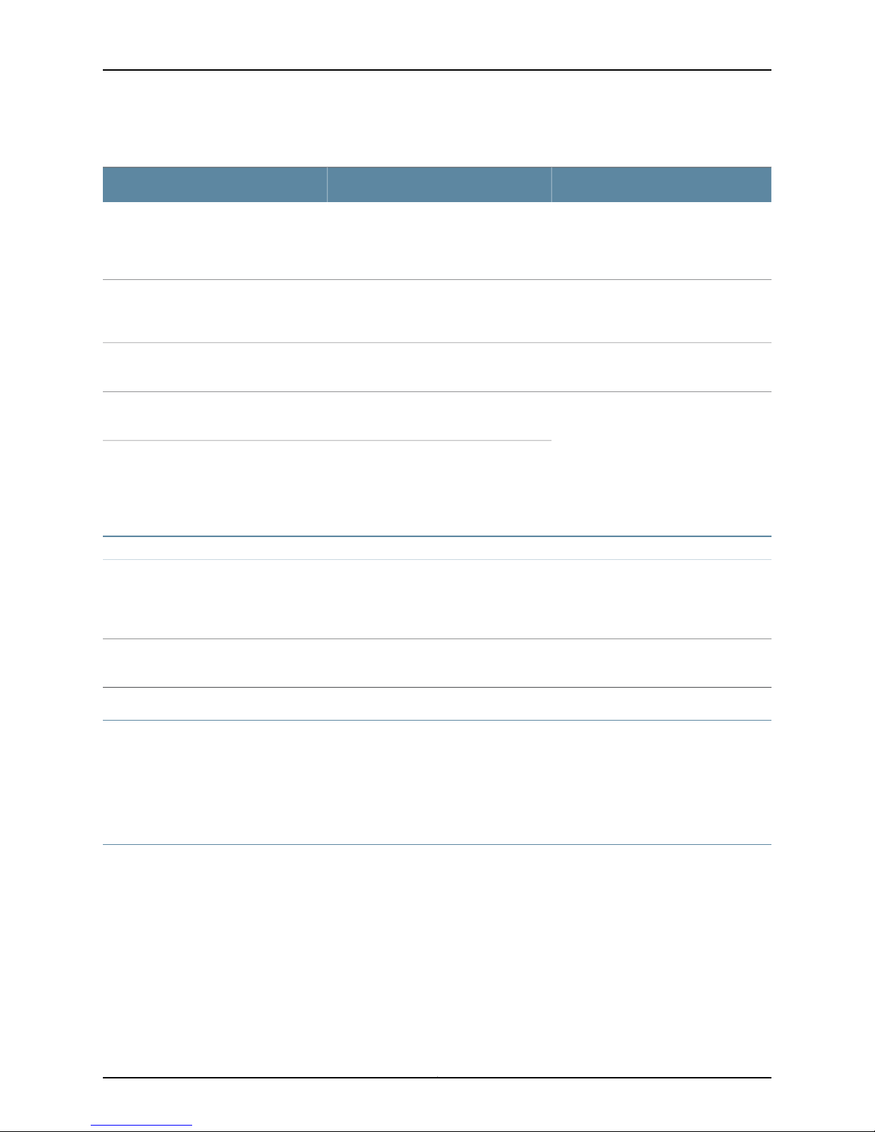
Table 2: Text and Syntax Conventions (continued)
About This Guide
ExamplesDescriptionConvention
| (pipe symbol)
# (pound sign)
[ ] (square brackets)
Indention and braces ( { } )
; (semicolon)
GUI Conventions
Bold text like this
Indicates a choice between the mutually
exclusivekeywords or variables on either
side of the symbol. The set of choices is
often enclosed in parentheses for clarity.
same lineas the configuration statement
to which it applies.
Encloses a variable for which you can
substitute one or more values.
Identifies a level in the configuration
hierarchy.
Identifies a leaf statement at a
configuration hierarchy level.
Representsgraphicaluser interface (GUI)
items you click or select.
broadcast | multicast
(string1 | string2 | string3)
rsvp { # Required for dynamic MPLS onlyIndicates a comment specified on the
community name members [
community-ids ]
[edit]
routing-options {
static {
route default {
nexthop address;
retain;
}
}
}
•
In the Logical Interfaces box, select
All Interfaces.
•
To cancel the configuration, click
Cancel.
> (bold right angle bracket)
Separates levels in a hierarchy of menu
selections.
SRX Series Documentation and Release Notes
For a list of related SRX Series documentation, see
http://www.juniper.net/techpubs/hardware/srx-series-main.html . If the information in
the latest SRX Series Release Notes differs from the information in the documentation,
follow the SRX Series Release Notes.
Obtaining Documentation
To obtain the most current version of all Juniper Networks technical documentation, see
the products documentation page on the Juniper Networks website at
www.juniper.net/techpubs/ .
To order printed copies of this guide and other Juniper Networks technical documents,
contact your sales representative.
Copies of the Management Information Bases (MIBs) available in a software release are
available at http://www.juniper.net .
In the configuration editor hierarchy,
select Protocols>Ospf.
xiCopyright © 2013, Juniper Networks, Inc.
Page 12

SRX3400 Services Gateway Hardware Guide
Documentation Feedback
We encourage you to provide feedback, comments, and suggestions so that we can
improve the documentation. You can send your comments to
[email protected] , or fill out the documentation feedback form at
http://www.juniper.net/techpubs/docbug/docbugreport.html . If you are using e-mail, be
sure to include the following information with your comments:
•
Document name
•
Document part number
•
Page number
•
Software release version (not required for Network Operations Guides [NOGs])
Requesting Technical Support
Technical product support is available through theJuniper Networks Technical Assistance
Center (JTAC). If you are a customer with an active J-Care or JNASC support contract,
or are covered under warranty, and need postsales technical support, you can access
our tools and resources online or open a case with JTAC.
•
JTAC policies—For a complete understanding of our JTAC procedures and policies,
review the JTAC User Guide located at
www.juniper.net/customers/support/downloads/710059.pdf.
•
Product warranties—For product warranty information, visit
www.juniper.net/support/warranty.
•
JTAC Hours of Operation—The JTAC centers have resources available 24 hours a day,
7 days a week, 365 days a year.
Self-Help Online Tools and Resources
For quick and easy problem resolution, Juniper Networks has designed an online
self-service portal called the Customer Support Center (CSC) that provides you with the
following features:
•
Find CSC offerings: www.juniper.net/customers/support
•
Find product documentation: www.juniper.net/techpubs/
•
Download the latest versions of software and review release notes:
www.juniper.net/customers/csc/software
•
Find solutions and answer questions using our Knowledge Base: kb.juniper.net
•
Search technical bulletins for relevant hardware and software notifications:
https://www.juniper.net/alerts
Copyright © 2013, Juniper Networks, Inc.xii
Page 13

About This Guide
•
Join and participate in the Juniper Networks Community Forum:
www.juniper.net/company/communities
•
Open a case online in the CSC Case Manager: www.juniper.net/cm
To verify service entitlement by productserial number, use our Serial NumberEntitlement
(SNE) Tool located at https://tools.juniper.net/SerialNumberEntitlementSearch.
Opening a Case with JTAC
You can open a case with JTAC on the Web or by telephone.
•
Use the Case Manager tool in the CSC at www.juniper.net/cm.
•
Call 1-888-314-JTAC (1-888-314-5822 toll-free in the USA, Canada, and Mexico).
For international or direct-dial options in countries without toll-free numbers, visit us at
www.juniper.net/support/requesting-support.html.
xiiiCopyright © 2013, Juniper Networks, Inc.
Page 14

SRX3400 Services Gateway Hardware Guide
Copyright © 2013, Juniper Networks, Inc.xiv
Page 15

PART 1
SRX3400 Services Gateway Overview
•
Introduction to the SRX3400 Services Gateway on page 3
•
SRX3400 Services Gateway Hardware Components on page 7
1Copyright © 2013, Juniper Networks, Inc.
Page 16

SRX3400 Services Gateway Hardware Guide
Copyright © 2013, Juniper Networks, Inc.2
Page 17
CHAPTER 1
Cooling
air exhaust
ESD
point
IOC in
slot 1
SFB
USB
ports
Console
port
g036122
Slot
number
guide
CFM slots
for SPCs, IOCs,
or NP-IOCs
Management
Ethernet port
Introduction to the SRX3400 Services
Gateway
This section includes the following topics:
•
SRX3400 Services Gateway Description on page 3
•
SRX3400 Services Gateway Performance and Features on page 4
•
SRX3400 Services Gateway Physical Specifications on page 4
SRX3400 Services Gateway Description
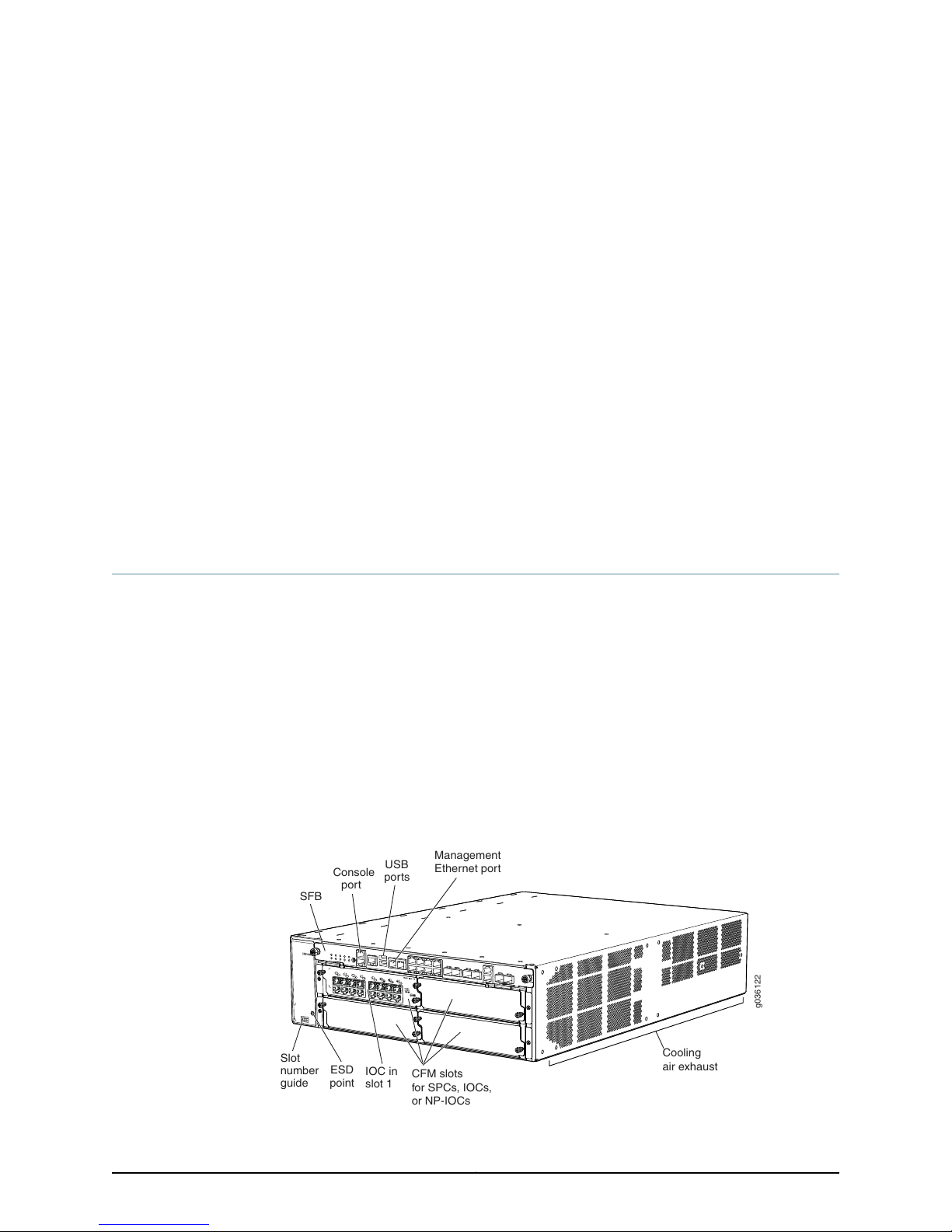
The SRX3400 Services Gateway is a high-performance, scalable, carrier-class security
device with multi-processor architecture. The services gateway has a capacity of up to
20 gigabits per second (Gbps) in full duplex and is three rack units (U) tall. Sixteen
services gateways can be stacked in a single floor-to-ceiling rack, for increased port
density per unit of floorspace.The services gatewayprovidesseven common form-factor
module (CFM) slots that can be populated with up to four Services Processing Cards
(SPCs), up to two Network Processing Cards (NPCs), up to four I/O cards (IOCs), and
up to six Network Processing I/O cards (NP-IOCs). The services gateway also has one
dedicated slot for the Switch Fabric Board (SFB), one slot for a Routing Engine, one slot
for an SRX Clustering Module (SCM), two slots for power supplies, and one slot for the
fan tray and air filter.
Figure 1: SRX3400 Services Gateway
3Copyright © 2013, Juniper Networks, Inc.
Page 18

SRX3400 Services Gateway Hardware Guide
Related
Documentation
SRX3400 Services Gateway Performance and Features on page 4•
• SRX3400 Services Gateway Physical Specifications on page 4
• SRX3400 Services Gateway Physical Specifications on page 4SRX3400 Services
Gateway Chassis on page 7
SRX3400 Services Gateway Performance and Features
Table 3 on page 4 summarizes the performance and basic features of the SRX3400
Services Gateway.
Table 3: Summary of SRX3400 Services Gateway Features
3 U (5.25 in.)Chassis height
Base configuration (built-in ports) 12 x 10/100/1000 Mbps
Plus up to four IOCs of the available types.
•
1 for nonredundant configuration
•
2 for redundant configuration
Related
Documentation
Physical ports
Power supplies
Available Components for the SRX3400 Services Gateway on page 9•
• SRX3400 Services Gateway Physical Specifications on page 4
• SRX3400 Services Gateway Chassis on page 7
SRX3400 Services Gateway Physical Specifications
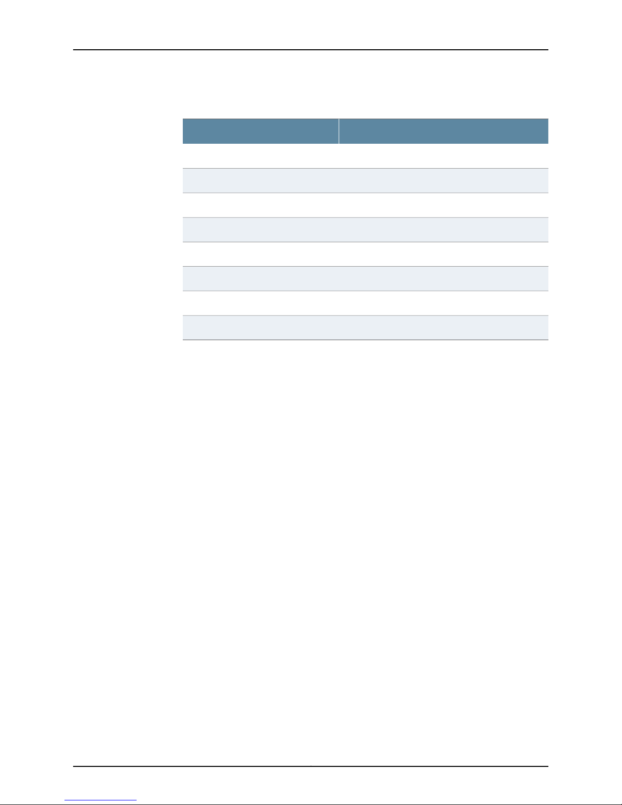
Table 4 on page 4 summarizes the physical specifications for the services gateway
chassis.
Table 4: Physical Specifications
ValueDescription
Chassis dimensions
Services gateway weight
5.25 in. (13.3 cm) high
17.5 in. (44.5 cm) wide
25.5 in. (64.8 cm) deep (from front-mounting bracket
to chassis rear)
Chassis with midplane, SFB, Routing Engine, fan tray,
air filter, and AC power module: 51 lb (23 kg)
Maximum configuration: 77 lb (35 kg)
2.9 lb (1.3 kg)Routing Engine weight
2.0 lb (0.9 kg)SCM weight
Copyright © 2013, Juniper Networks, Inc.4
Page 19
Chapter 1: Introduction to the SRX3400 Services Gateway
Table 4: Physical Specifications (continued)
ValueDescription
5.1 lb (2.3 kg)SFB weight
2.2 lb (1.0 kg)NPC weight
3.7 lb (1.7 kg)SPC weight
2.4 lb (1.1 kg)IOC weight
4.2 lb (1.9 kg)Fan tray weight
0.2 lb (0.09 kg)Air filter weight
2.9 lb (1.3 kg)DC power supply weight
3.1 lb (1.4 kg)AC power supply weight
Related
Documentation
• Available Components for the SRX3400 Services Gateway on page 9
• Hardware Component Locations in the SRX3400 Services Gateway Chassis on page 11
• SRX3400 Services Gateway Chassis on page 7
5Copyright © 2013, Juniper Networks, Inc.
Page 20

SRX3400 Services Gateway Hardware Guide
Copyright © 2013, Juniper Networks, Inc.6
Page 21

CHAPTER 2
SRX3400 Services Gateway Hardware
Components
Nearly all components of the SRX3400 Services Gateway are field-replaceable units
(FRUs), including the Switch Fabric Board (SFB), Routing Engine, Network Processing
Cards (NPCs), Service Processing Cards (SPCs), and I/O cards (IOCs), power supply,
fan tray, filter, and air deflector kits. To replace any of these components in your services
gateway, see “Field-Replaceable Units on the SRX3400 Services Gateway” on page 109.
This section includes the following topics:
•
SRX3400 Services Gateway Chassis on page 7
•
SRX3400 Services Gateway Component Basics on page 9
•
SRX3400 Services Gateway Midplane on page 13
•
SRX3400 Services Gateway Switch Fabric Board on page 14
•
SRX3400 Services Gateway NPCs on page 20
•
SRX3400 Services Gateway SPCs on page 20
•
SRX3400 Services Gateway IOCs on page 21
•
SRX3400 Services Gateway NP-IOCs on page 22
•
SRX3400 Services Gateway Routing Engine on page 23
•
SRX3400 Services Gateway SRX Clustering Module on page 24
•
SRX3400 Services Gateway Power Supplies on page 25
•
SRX3400 Services Gateway Fan Tray on page 29
•
SRX3400 and SRX5600 Services Gateways Air Deflector Kits on page 31
SRX3400 Services Gateway Chassis
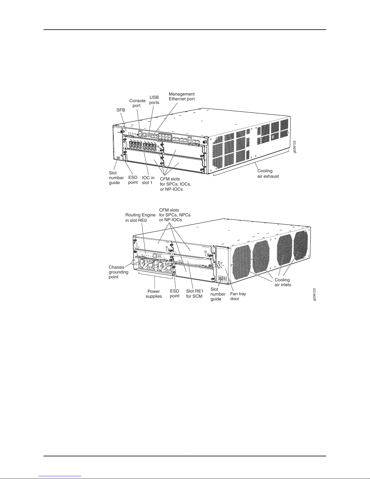
The SRX3400 Services Gateway chassis, shown in Figure 2 on page 8 and
Figure 3 on page 8, is a rigid sheet metal structure that houses all of the other services
gateway components. The chassis measures 5.25 in. (13.3 cm) high, 17.5 in. (44.5 cm)
wide, and 25.5 in. (64.8 cm) deep (from the front to the rear of the chassis). The chassis
installs in standard 800–mm (or larger) enclosed cabinets, 19 in. equipment racks, or
telecommunications open-frame racks. Up to 16 services gateways can be installed in
7Copyright © 2013, Juniper Networks, Inc.
Page 22
Cooling
air exhaust
ESD
point
IOC in
slot 1
SFB
USB
ports
Console
port
g036122
Slot
number
guide
CFM slots
for SPCs, IOCs,
or NP-IOCs
Management
Ethernet port
ESD
point
Power
supplies
Routing Engine
in slot RE0
Chassis
grounding
point
Fan tray
door
Cooling
air inlets
Slot
number
guide
Slot RE1
for SCM
g036123
CFM slots
for SPCs, NPCs
or NP-IOCs
SRX3400 Services Gateway Hardware Guide
one standard (48-U) rack if the rack can handle their combined weight, which can be
greater than 1,232 lb (560 kg).
Figure 2: Front View of the SRX3400 Services Gateway
Related
Documentation
Figure 3: Rear View of the SRX3400 Services Gateway
SRX3400 Services Gateway Description on page 3•
• SRX3400 Services Gateway Common Form-Factor Modules on page 9
• Available Components for the SRX3400 Services Gateway on page 9
• Grounding the SRX3400 Services Gateway on page 76
• SRX3400 Services Gateway General Safety Guidelines and Warnings on page 141
Copyright © 2013, Juniper Networks, Inc.8
Page 23

Chapter 2: SRX3400 Services Gateway Hardware Components
SRX3400 Services Gateway Component Basics
This section describesthe cardform factors, the servicesgateway components available,
and where they can be installed in the SRX3400 Services Gateway. It also describes the
flow of data through the services gateway. This section includes the following topics:
•
SRX3400 Services Gateway CFMs on page 9
•
Available Components for the SRX3400 Services Gateway on page 9
•
Hardware Component Locations in the SRX3400 Services Gateway Chassis on page 11
•
Data Flow in the SRX3400 Services Gateway on page 13
SRX3400 Services Gateway CFMs
The services gateway chassis supports common form-factor modules (CFMs). A
single-wide module format and a double-wide module format are available. I/O card
(IOC), Services Processing Card (SPC), and Network Processing Card (NPC) modules
are in single-wide CFM format. The Switch Fabric Board (SFB), Routing Engine, and SRX
Clustering Module (SCM) are not in CFM format, and thus have assigned slots within the
chassis. With the interchangeability among the IOCs, SPCs, and NPCs, you have more
flexibility and scalability when deploying your networks based on the requirements in
the field. For example, if you need more ports and bigger oversubscription ratio, then you
can load more slots with IOCs; on the other hand, if you need smaller oversubscription
ratio for better QoS behavior, or you need more security services, then you can load more
slots with SPCs and only use the on-board network interface ports.
Related
Documentation
Installing CFM Cards in the SRX3400 Services Gateway on page 59•
• SRX3400 Services Gateway Description on page 3
• Hardware Component Locations in the SRX3400 Services Gateway Chassis on page 11
• Available Components for the SRX3400 Services Gateway on page 9
• Data Flow in the SRX3400 Services Gateway on page 13
Available Components for the SRX3400 Services Gateway
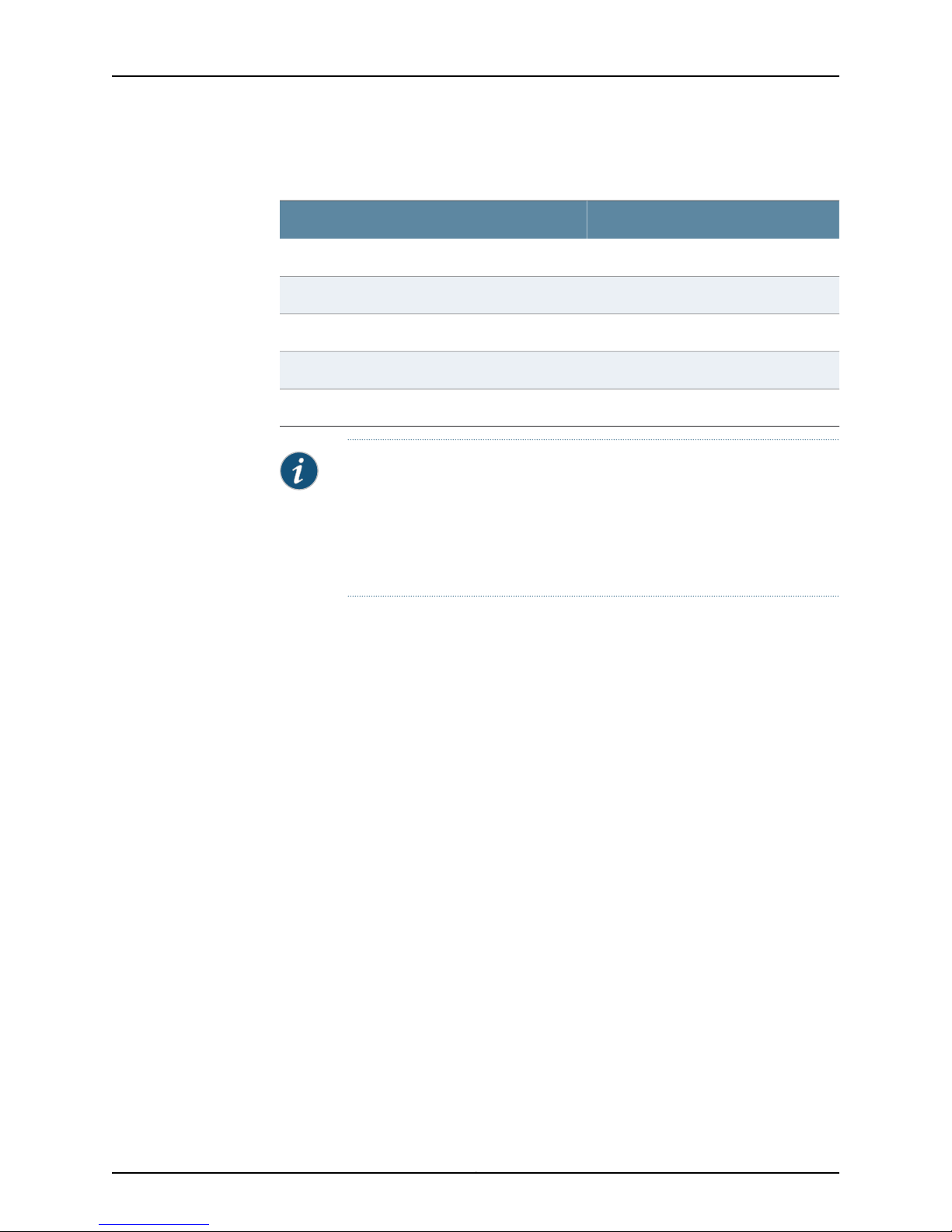
Table 5 on page 9 lists the various components, and the number of each, that can be
installed in the SRX3400 Services Gateway.
Table 5: Available SRX3400 Services Gateway Hardware Components
Minimum/MaximumHardware Component
1 requiredSwitch Fabric Board (SFB)
1 requiredRouting Engine
1 allowedSRX Clustering Module (SCM)
Up to 4 allowedI/O cards (IOCs)
9Copyright © 2013, Juniper Networks, Inc.
Page 24
SRX3400 Services Gateway Hardware Guide
Table 5: Available SRX3400 Services Gateway Hardware
Components (continued)
Minimum/MaximumHardware Component
Up to 6 allowed (see note below)Network Processing I/O Cards (NP-IOCs)
1 required, 2 allowedNetwork Processing Cards (NPCs)
1 required, up to 4 allowedServices Processing Cards (SPCs)
1 required, up to 2 allowedPower supply
1 requiredFan tray (containing multiple fans)
NOTE: A minimum configuration must include one SPC and either one NPC
or one NP-IOC. However, if there are no NPCs in the chassis, the Ethernet
ports on the SFB will not be functional. See “SRX3400 Services Gateway
Network Processing Cards” on page 20, “SRX3400 Services Gateway
NP-IOCs” on page 22, and “SRX3400 Services GatewayServices Processing
Cards” on page 20 for details about these cards.
Copyright © 2013, Juniper Networks, Inc.10
Page 25
Chapter 2: SRX3400 Services Gateway Hardware Components
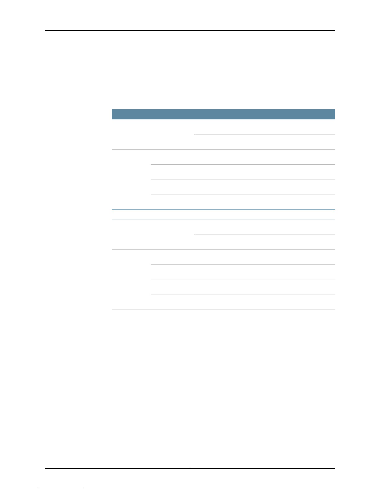
Table 6 on page 11 shows the supported combinations of SPCs, NPCs, and IOCs that
can be installed in the SRX3400 Services Gateway. The support is different between
standard and enhanced DC-powered services gatewaysbecause the standard DC power
supplies have a lower power rating.
Table 6: Supported Combinations of SPCs, NPCs, and IOCs
AC Power Supplies or Enhanced DC Power Supplies
NPCs
21
4 IOCs4 IOCs1SPCs
3 IOCs4 IOCs2
2 IOCs3 IOCs3
1 IOC2 IOCs4
Standard DC Power Supplies
NPCs
21
4 IOCs4 IOCs1SPCs
3 IOCs4 IOCs2
1 IOCs2 IOCs3
Not supported0 IOCs4
Related
Documentation
SRX3400 Services Gateway Chassis on page 7•
• Hardware Component Locations in the SRX3400 Services Gateway Chassis on page 11
• Data Flow in the SRX3400 Services Gateway on page 13
Hardware Component Locations in the SRX3400 Services Gateway Chassis
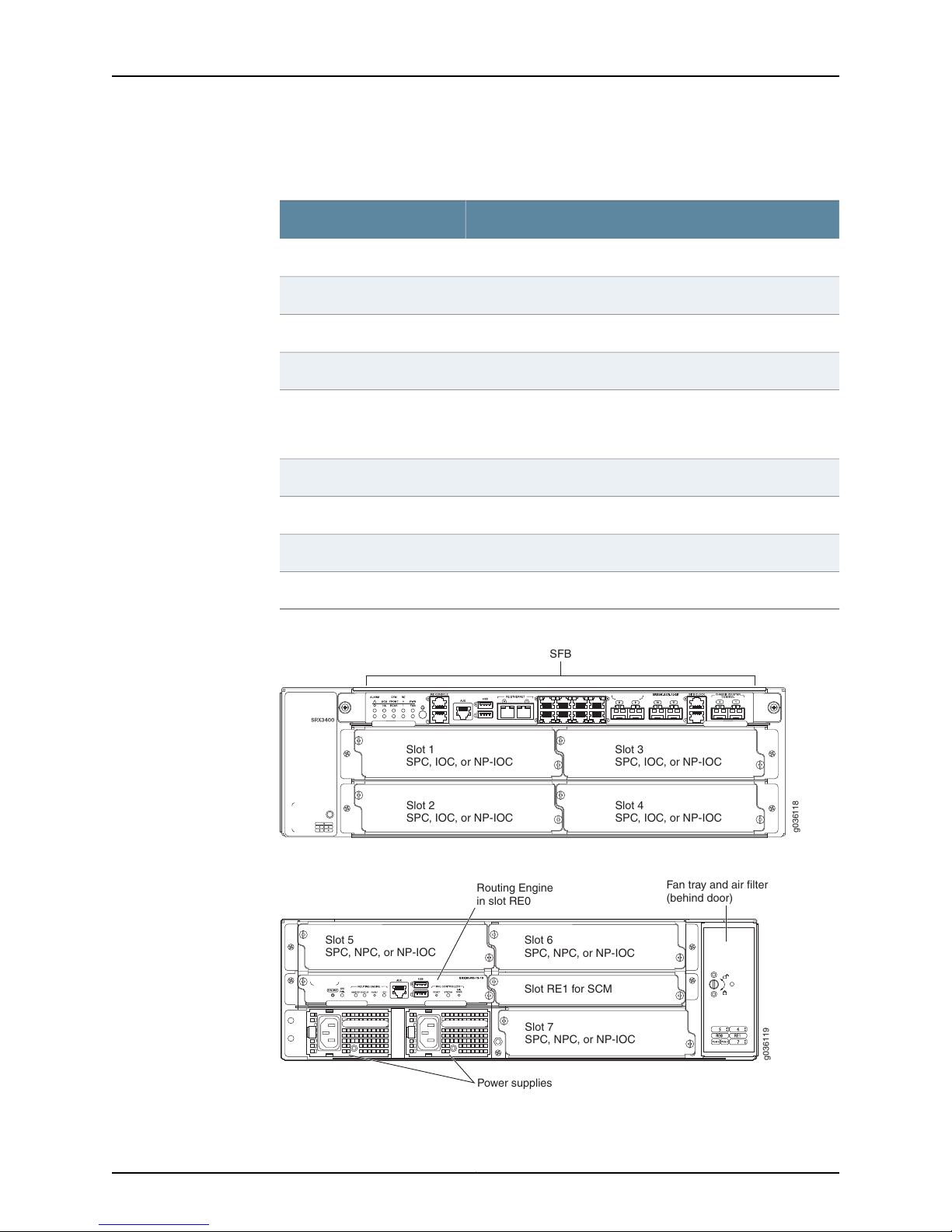
The SRX3400 Services Gateway is populated with one SFB, one Routing Engine, one
power supply, and a fan tray plus air filter at the factory. You must install all other cards
required to meet your configuration needs. Table 7 on page 12 lists the possible locations
of the various hardware components in the SRX3400 Services Gateway.
Figure 4 on page 12 and Figure 5 on page 12 show the locations of the slots and the
applicable modules.
11Copyright © 2013, Juniper Networks, Inc.
Page 26
g036118
SFB
Slot 1
SPC, IOC, or NP-IOC
Slot 3
SPC, IOC, or NP-IOC
Slot 2
SPC, IOC, or NP-IOC
Slot 4
SPC, IOC, or NP-IOC
g036119
Routing Engine
in slot RE0
Power supplies
Slot 5
SPC, NPC, or NP-IOC
Slot 6
SPC, NPC, or NP-IOC
Slot 7
SPC, NPC, or NP-IOC
Fan tray and air filter
(behind door)
Slot RE1 for SCM
SRX3400 Services Gateway Hardware Guide
Table 7: Allowed Slot Locations for the SRX3400 Services Gateway
Components
Allowed Slot LocationsModule Name
Front slot labeled 0.SFB
Rear slot labeled RE0.Routing Engine
Rear slot labeled RE1.SCM
Front slots labeled 1-4.IOCs
NP-IOCs
Front slots labeled 1-4 and rearslotslabeled5-7. We recommend
that you install NP-IOCs in front panel slots to simplify cable
management.
Rear slots labeled 5-7.NPCs
Front slots labeled 1-4 and rear slots labeled 5-7.SPCs
Rear slots (two) on bottom left of chassis.Power supplies
Rear, vertical slot on far right of chassis.Fan tray and air filter
Figure 4: Front Slots on the SRX3400 Services Gateway
Figure 5: Rear Slots on the SRX3400 Services Gateway
Copyright © 2013, Juniper Networks, Inc.12
Page 27

Chapter 2: SRX3400 Services Gateway Hardware Components
NOTE: A minimum configuration must include one SPC and either one NPC
or one NP-IOC. However, if there are no NPCs in the chassis, the Ethernet
ports in the SFB will not be functional. See “SRX3400 Services Gateway
NetworkProcessingCards” on page20, “SRX3400 Services Gateway Services
Processing Cards” on page 20 for details about these cards.
Related
Documentation
SRX3400 Services Gateway Chassis on page 7•
• Available Components for the SRX3400 Services Gateway on page 9
• Installing CFM Cards in the SRX3400 Services Gateway on page 59
• Data Flow in the SRX3400 Services Gateway on page 13
• Installation Overview for the SRX3400 Services Gateway on page 49
Data Flow in the SRX3400 Services Gateway
The services gateway receives data from the various physical interfaces on the I/O cards
(IOCs). Incoming data is passed through the Switch Fabric Board (SFB) to a Network
Processing Card (NPC), back to the SFB and on to a Services Processing Card (SPC).
The data is then passed out of the services gateway in reverse order—to the SFB, NPC,
SFB, and out to the IOC.
Related
Documentation
SRX3400 Services Gateway Chassis on page 7•
• Available Components for the SRX3400 Services Gateway on page 9
• Hardware Component Locations in the SRX3400 Services Gateway Chassis on page 11
• Installation Overview for the SRX3400 Services Gateway on page 49
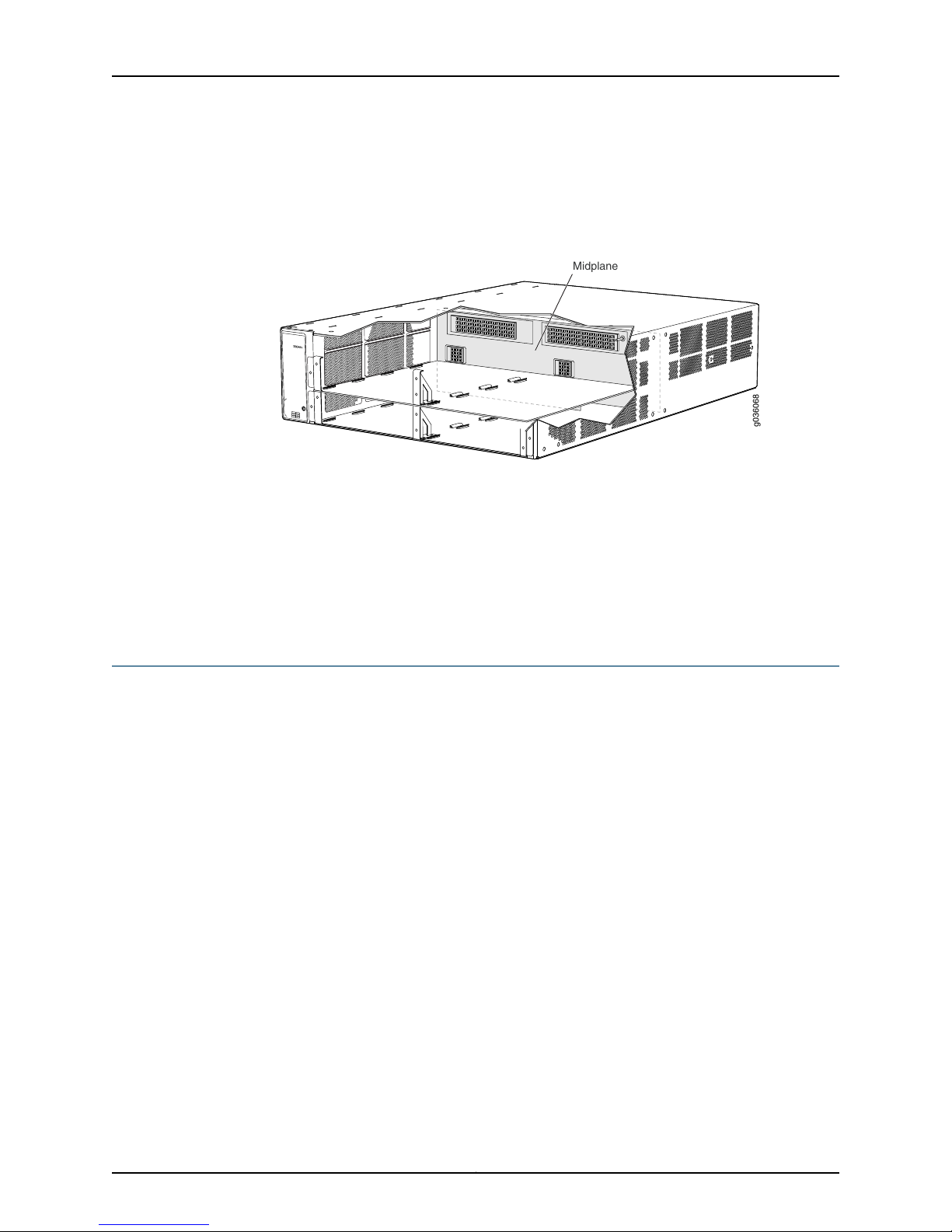
SRX3400 Services Gateway Midplane
The midplane in the SRX3400 Services Gateway is in the center of the chassis and
provides connections for installing up to four common form-factor modules (CFMs)
through the front of the chassis and up to three CFMs through the rear of the chassis.
See “Hardware Component Locations in the SRX3400 Services Gateway Chassis” on
page 11 for details about where the individual modules can be installed. The power
supplies install into the midplane from the rear of the chassis. The cooling system
components also connect to the midplane.
The midplane performs the following major functions:
•
Data path—Data packets are transferred across the midplane between the IOCs and
SPCs through the fabric ASICs on the SFBs.
•
Power distribution—The services gateway power supplies are connected to the
midplane, which distributes power to all of the services gateway components.
13Copyright © 2013, Juniper Networks, Inc.
Page 28
Midplane
g036068
SRX3400 Services Gateway Hardware Guide
•
Signal path—The midplane provides the signal path to the IOCs, SFBs, SPCs, Routing
Engine, and other services gateway components for monitoring and control of the
system.
Figure 6: Midplane
Related
Documentation
SRX3400 Services Gateway Chassis on page 7•
• Available Components for the SRX3400 Services Gateway on page 9
• SRX3400 Services Gateway Switch Fabric Board on page 14
• SRX3400 Services Gateway Network Processing Cards on page 20
• SRX3400 Services Gateway Services Processing Cards on page 20
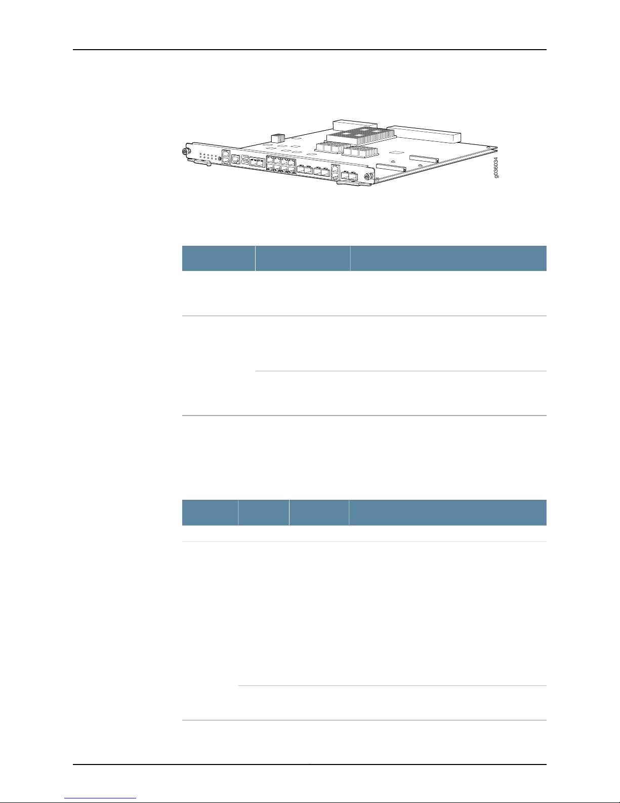
SRX3400 Services Gateway Switch Fabric Board
The Switch Fabric Board (SFB) is the data plane for the subsystems in the chassis. The
SFB performs the following functions:
•
Powers the services gateway on and off
•
Controls clocking and distribution
•
Provides eight copper Gigabit Ethernet ports and four fiber Gigabit Ethernet ports
•
Provides two high availability (HA) Control ports
•
Provides interconnections to all the IOCs within the chassis through integrated switch
fabrics
•
Handles arbitration among the CFMs
•
Handles switching among multiple SPCs if present
•
Provides service ports, system LEDs, and operational buttons on the front panel
Copyright © 2013, Juniper Networks, Inc.14
Page 29
g036034
Chapter 2: SRX3400 Services Gateway Hardware Components
Figure 7: Switch Fabric Board
Table 8 on page 15 describes the behavior of the Power button near the left end of the
SFB front panel.
Table 8: Power Button Behavior
ResultActionCondition
Services
gateway
powered off
Services
gateway
powered on
Short push (3 to 5
seconds)
Short push (3 to 5
seconds)
Long push (15 seconds
or more)
Powers the services gateway on. The PWR LED
blinks to show you that the Routing Engine is
initializing.
Initiates a graceful shutdown that preserves the
services gateway state information. The PWR LED
blinks to show you that the services gateway is
shutting down.
Initiates an immediate shutdown. The services
gateway state information will be lost. Avoid using
immediate shutdown unless necessary.
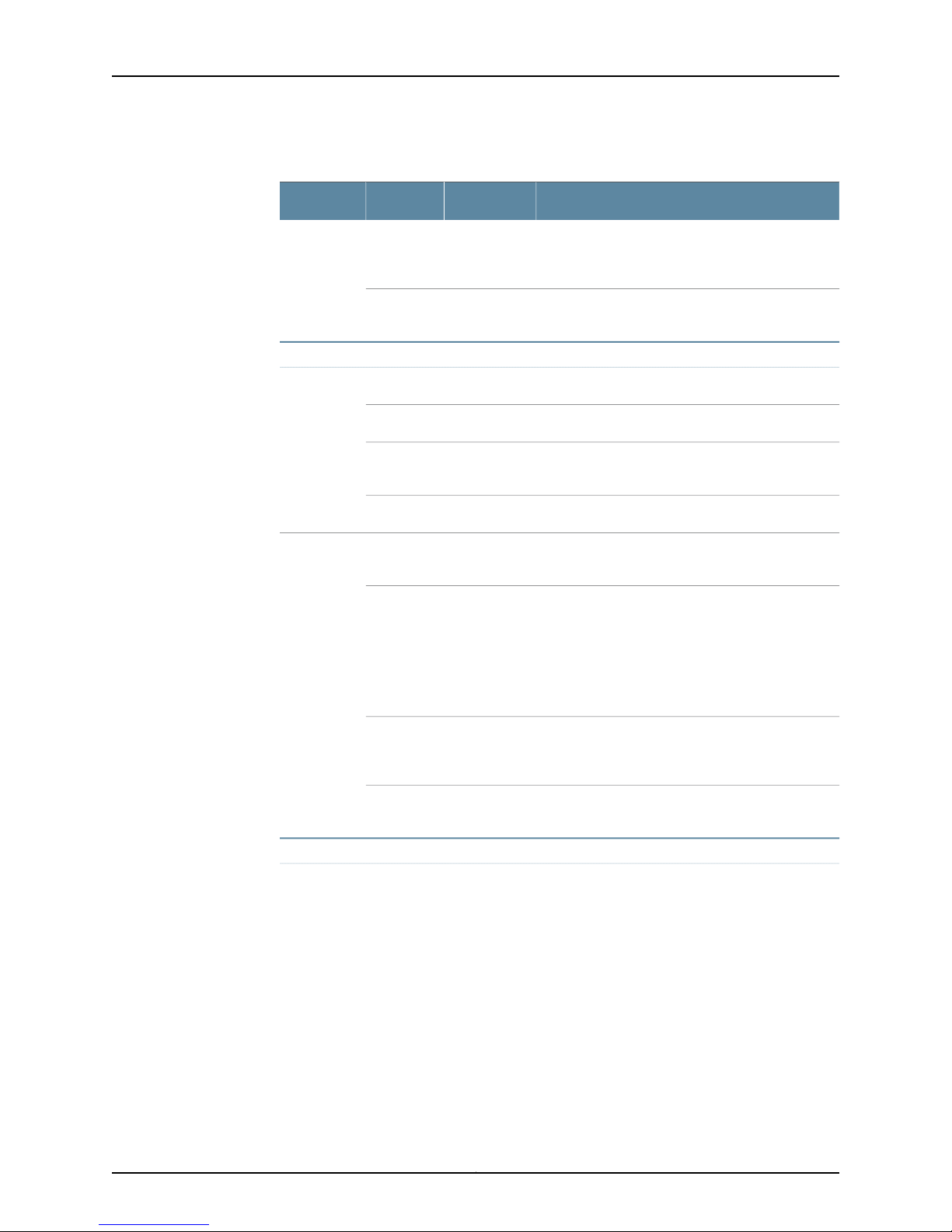
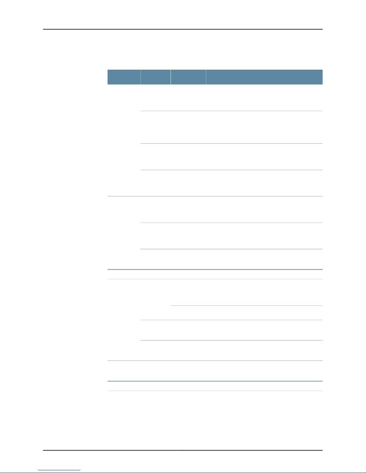
Table 9 on page 15 describes the system behavior indicated by the various LEDs on the
front panel of the SFB. LEDs are listed based on their location on the services gateway,
from left to right. Table 10 on page 18 describes the ports/connections available on the
front panel of the SFB.
Table 9: Switch Fabric Board LED Indicators
Indicated BehaviorStatusColorLabel
Alarm (pair)
On steadilyYellowNon-Critical
(Top)
A noncritical alarm is present in the system.
Examples of noncritical alarms include:
(unlit)
•
Memory usageis high onthe ServicesProcessing
Unit (SPU); less than 10% available.
•
The maximum number of sessions has been
reached.
•
The maximum number of tunnels has been
reached.
•
HA status has changed.
•
Services gateway temperature is too warm.
No alarms are present in the system.OffDark
15Copyright © 2013, Juniper Networks, Inc.
Page 30
SRX3400 Services Gateway Hardware Guide
Table 9: Switch Fabric Board LED Indicators (continued)
Indicated BehaviorStatusColorLabel
(Bottom)
(unlit)
SFB and HA (pair)
On steadilyRedCritical
On steadilyAmber
On steadilyGreenHA
On steadilyAmber
A criticalalarm ispresent inthe system. A hardware
component or software module has failed, or the
network management interface is down.
No critical alarms are present in the system.OffDark
The SFB is operating normally.On steadilyGreenSFB
The SFB is initializing.BlinkingGreen
The switch fabric is operating normally, but the
Ethernet interfaces are not operating normally.
The SFB has failed and is not operating normally.On steadilyRed
High availability is operating normally. All cluster
members and all HA links are available.
An alarm is present on the HA link. All cluster
members are present, but some HA links are down.
There are still enough links for full functionality, but
performancecouldbe impaired (reducedbandwidth
could cause packets to get dropped, or reduced
resiliency as a single point of failure might now
exist).
(unlit)
CFM Status (pair)
On steadilyRed
OffDark
A critical alarm is present on the HA. One or more
cluster members are missing or unreachable; or
active when secondary-path is engaged.
HA is disabled—Services gateway is not configured
for clustering or HA is disabled by secondary path.
Copyright © 2013, Juniper Networks, Inc.16
Page 31
Chapter 2: SRX3400 Services Gateway Hardware Components
Table 9: Switch Fabric Board LED Indicators (continued)
Indicated BehaviorStatusColorLabel
(top)
(bottom)
(unlit)
(unlit)
On steadilyGreenSERVICE
On steadilyAmber
On steadilyRed
OffDark
On steadilyGreenOK/FAIL
On steadilyRed
OffDark
The SFB and all installed CFM cards are operating
normally. The SERVICE LEDs on all installed CFM
cards are green.
The SFB or one or more of the installed CFM cards
has reported a minor error condition. The SERVICE
LEDs on the CFM cards reporting the error are
amber.
The SFB or one or more of the installed CFM cards
has failed. The SERVICE LEDs on the failed CFM
cards are red.
One ormore ofthe installed CFMcards are disabled.
The SERVICE LEDs on the disabled CFM cards are
dark.
The SFB and all installed CFM cards are operating
normally. The OK/FAIL LEDs on all installed CFM
cards are green.
The SFB or one or more of the installed CFM cards
has failed. The OK/FAIL LEDs on the failed CFM
cards are red.
One or more of the installed CFM cards are offline.
The OK/FAIL LEDs on the offline CFM cardsare dark.
Routing Engine Status (pair)
On steadilyGreenRE0 (top)
On steadilyRed
(unlit)
Unused.RE1
(bottom)
Power and Fan (pair)
The Routing Engine in RE0 is functioning as the
master Routing Engine. Only one Routing Engine
can be installed.
The Routing Engine in slot RE0 is initializing.Blinking
Either the Routing Engine orControl Board function
on RE0 has failed and is not operating normally.
The RE0 slot is empty.OffDark
17Copyright © 2013, Juniper Networks, Inc.
Page 32
SRX3400 Services Gateway Hardware Guide
Table 9: Switch Fabric Board LED Indicators (continued)
Indicated BehaviorStatusColorLabel
(bottom)
(unlit)
On steadilyGreenPWR (top)
Blinking
On steadilyAmber
On steadilyRed
On steadilyRed
The services gateway is receiving power. The Power
Good signalfor allinstalled powersupplies has been
received after Routing Engine initialization.
The services gateway is in one of two states:
•
Services gateway is receiving power and is in the
process of booting up but has not yet initialized
the Routing Engine.
•
Services gateway is in the process of graceful
shutdown.
One of the power supplies has failed, but the power
available from the remaining power supplies is
sufficient to power all the installed components.
One or more of the power supplies have failed, and
the power available from the remaining power
supplies is not sufficient to power all the installed
components.
The services gateway is shut down.OffDark
The cooling system is operating normally.On steadilyGreenFAN
The cooling system has failed (one or more fans in
the fan tray are not operating normally).
NOTE: All SFB status LEDs remain unlit until Routing Engine initialization is
complete. The PWR LED blinks green until Routing Engine initialization is
complete, at which point the LED becomes solid green.
Table 10: Switch Fabric Board Front Panel Ports and Connectors
DescriptionPanel Label
RE CONSOLE 0
USB0 (top),
USB1 (bottom)
RJ-45 console port used to connect to the Routing Engine
inserted in slot RE0.
Unused.RE CONSOLE 1
Unused.AUX
Universal serial bus connectors that can be managed and
accessed by the master Routing Engine.
RJ-45 port used to manage the Routing Engine in slot RE0.RE ETHERNET 0
Copyright © 2013, Juniper Networks, Inc.18
Page 33

Chapter 2: SRX3400 Services Gateway Hardware Components
Table 10: Switch Fabric Board Front Panel Ports and
Connectors (continued)
DescriptionPanel Label
Unused.RE ETHERNET 1
Related
Documentation
(On-board copper Ethernet
ports)
(On-boardfiber Ethernetports)
BITSCLK1 (bottom)
CHASSIS CLUSTER CONTROL
0 (left),
CHASSIS CLUSTER CONTROL 1
(right)
Eight 10/100/1000 Ethernetovercopper media ports. The ports
use RJ-45 connectors and are numbered from 0-7, top to
bottom, left to right.
Four Ethernet over fiber media ports. The ports use small
form-factor connectors and are numbered8-11 from leftto right.
Also supports copper SFPs.
Unused.BITSCLK0 (top),
SFP high availability ports. CHASSIS CLUSTER CONTROL 0
connects to the control functions on the Routing Engine in slot
RE0. CHASSIS CLUSTER CONTROL 1 connects to the SRX
Clustering Module (SCM), if any, in slot RE1.
NOTE: We strongly recommend the use of Juniper Networks
SFP and XFP transceivers. We cannot guarantee correct
operation if other transceivers are used. The transceiver type
can bedifferentin eachport, as longas a supportedpart number
is used.
SRX3400 Services Gateway Chassis on page 7•
• Available Components for the SRX3400 Services Gateway on page 9
• SRX3400 Services Gateway Network Processing Cards on page 20
• SRX3400 Services Gateway Services Processing Cards on page 20
• SRX3400 Services Gateway NP-IOCs on page 22
19Copyright © 2013, Juniper Networks, Inc.
Page 34
g036033
S
R
X3K-NPC
SRX3400 Services Gateway Hardware Guide
SRX3400 Services Gateway NPCs
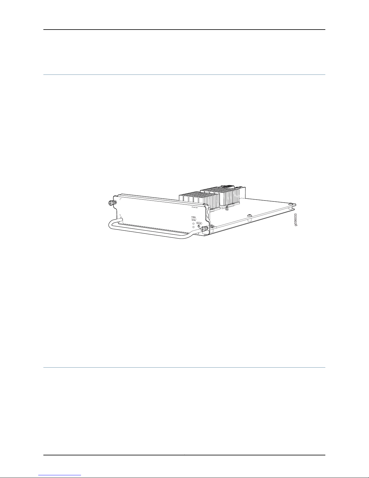
Network Processing Cards (NPCs) are common form-factor module (CFM) cards that
receive inbound traffic from I/O cards (IOCs) and direct it to the appropriate Services
Processing Card (SPC) for processing. Once services processing is complete, the NPC
receives outbound traffic from the SPC(s) and directs it back to the appropriate IOC.
Additionally, the NPC performs the following functions:
•
Buffers incoming traffic and queues outgoing traffic.
•
Performs advanced traffic management, including DoS/DDoS protective measures.
For example, it can drop traffic to or from a particular IP address, protecting from ICMP,
UDP, and TCP SYN flooding, and buffering bursty traffic to protect the Services
Processing Card (SPC).
Figure 8: Typical NPC
For detailed information about the NPCs supported by the services gateway, see the
SRX1400, SRX3400, and SRX3600 Services Gateway Module Guide at
www.juniper.net/techpubs/.
Related
Documentation
SRX3400 Services Gateway Chassis on page 7•
• Installing CFM Cards in the SRX3400 Services Gateway on page 59
• Available Components for the SRX3400 Services Gateway on page 9
• SRX3400 Services Gateway Switch Fabric Board on page 14
• SRX3400 Services Gateway Services Processing Cards on page 20
• SRX3400 Services Gateway IOCs on page 21
• SRX3400 Services Gateway NP-IOCs on page 22
SRX3400 Services Gateway SPCs
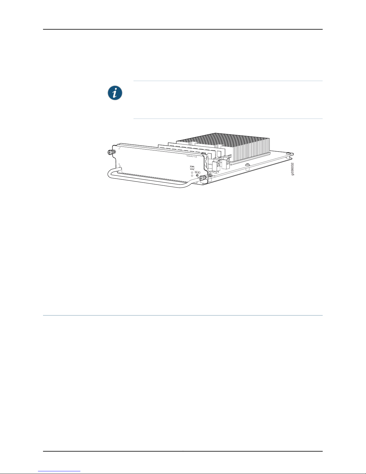
Services Processing Cards (SPCs) are common form-factor module (CFM) cards that
provide the processing power to run integrated services such as firewall, IPsec and IDP.
All traffic traversing the services gateway is passed to an SPC to have service processing
applied to it. Traffic is intelligently distributed by Network Processing Cards (NPCs) to
SPCs for service processing, including session setup based on policies, fast packet
processing for packets that match a session, encryption and decryption, and IKE
negotiation.
Copyright © 2013, Juniper Networks, Inc.20
Page 35
g036032
S
R
X3K-SPC-1-10-40
Chapter 2: SRX3400 Services Gateway Hardware Components
The services gateway must have at least one SPC installed. You can install additional
SPCs to increase services processing throughput.
NOTE: If a CFM slot is not occupied by a card, you must install a blank panel
to shield the empty slot and to allow cooling air to circulateproperly through
the services gateway.
Figure 9: Typical Services Processing Card
For detailed information about the SPCs supported by the services gateway, see the
SRX1400, SRX3400, and SRX3600 Services Gateway Module Guide at
www.juniper.net/techpubs/.
Related
Documentation
SRX3400 Services Gateway Chassis on page 7•
• Installing CFM Cards in the SRX3400 Services Gateway on page 59
• Available Components for the SRX3400 Services Gateway on page 9
• SRX3400 Services Gateway Switch Fabric Board on page 14
• SRX3400 Services Gateway Network Processing Cards on page 20
• SRX3400 Services Gateway IOCs on page 21
• SRX3400 Services Gateway NP-IOCs on page 22
SRX3400 Services Gateway IOCs
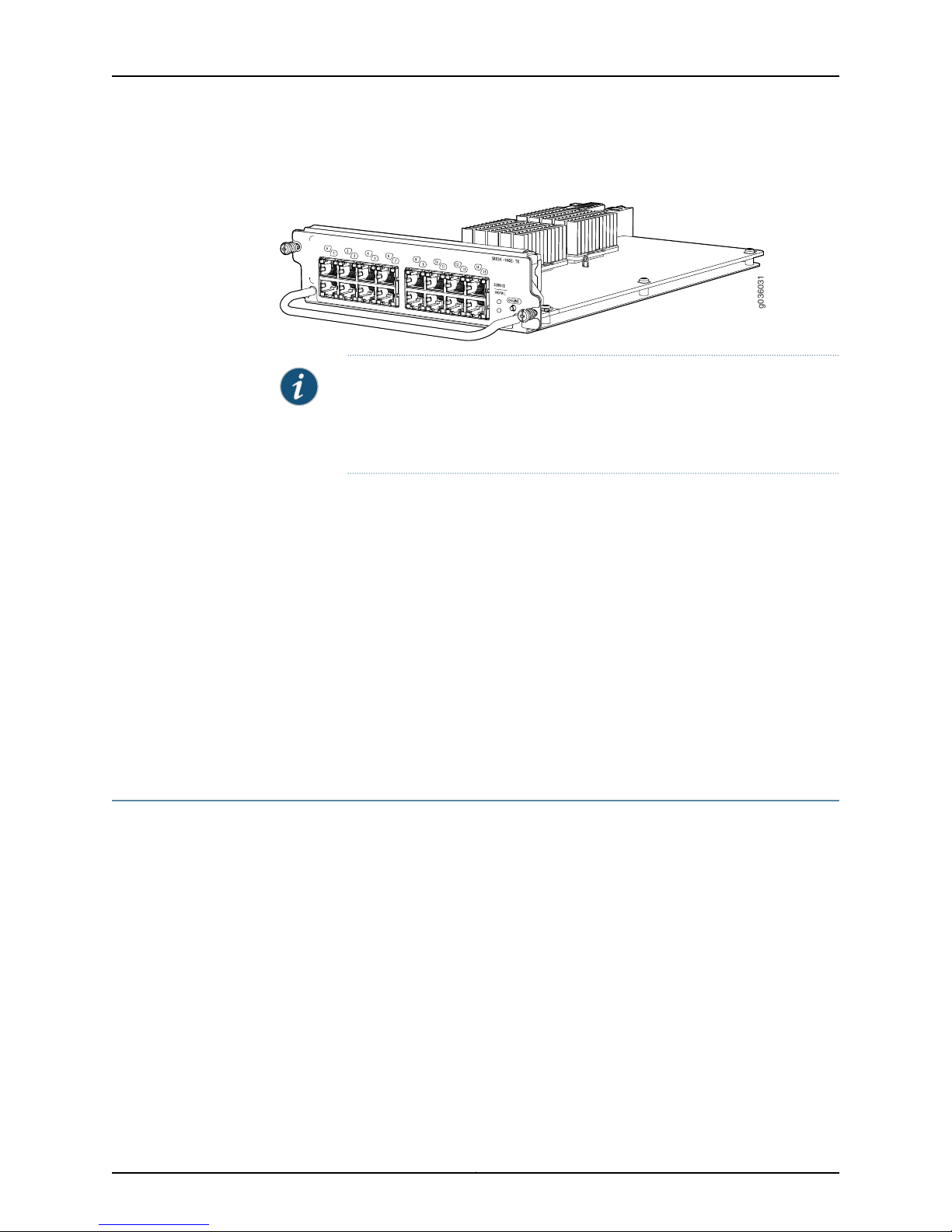
I/O cards (IOCs) are common form-factor module (CFM) cards that provide additional
physical network connections to the services gateway to supplement the Ethernet ports
on theSwitch Fabric Board(SFB). Theirprimary functionis todeliver data packets arriving
on the physical portsto the Network Processing Card (NPC) and to forward data packets
out the physical ports after services processing. The SRX3400 Services Gateway has
four slots in the front of the chassis where you can install IOCs. You can install any
combination of IOCs in the slots. Figure 10 on page 22 shows a typical IOC.
21Copyright © 2013, Juniper Networks, Inc.
Page 36
g036031
SRX3400 Services Gateway Hardware Guide
Figure 10: Typical IOC (16-Port Copper 10/100/1000 IOC Shown, Other
IOCs Similar)
For detailed information about the IOCs supported by the services gateway, see the
SRX1400, SRX3400, and SRX3600 Services Gateway Module Guide at
www.juniper.net/techpubs/.
NOTE: When the services gatewayis in the services offload mode supported
in Junos OS release 12.1X44-D10 and later, IOCs are only supported in front
panel slots 1 through 3. See the Junos OS documentationfor moreinformation
about services offload mode.
Related
Documentation
SRX3400 Services Gateway Chassis on page 7•
• Installing CFM Cards in the SRX3400 Services Gateway on page 59
• Available Components for the SRX3400 Services Gateway on page 9
• SRX3400 Services Gateway Switch Fabric Board on page 14
• SRX3400 Services Gateway Network Processing Cards on page 20
• SRX3400 Services Gateway Services Processing Cards on page 20
• SRX3400 Services Gateway NP-IOCs on page 22
SRX3400 Services Gateway NP-IOCs
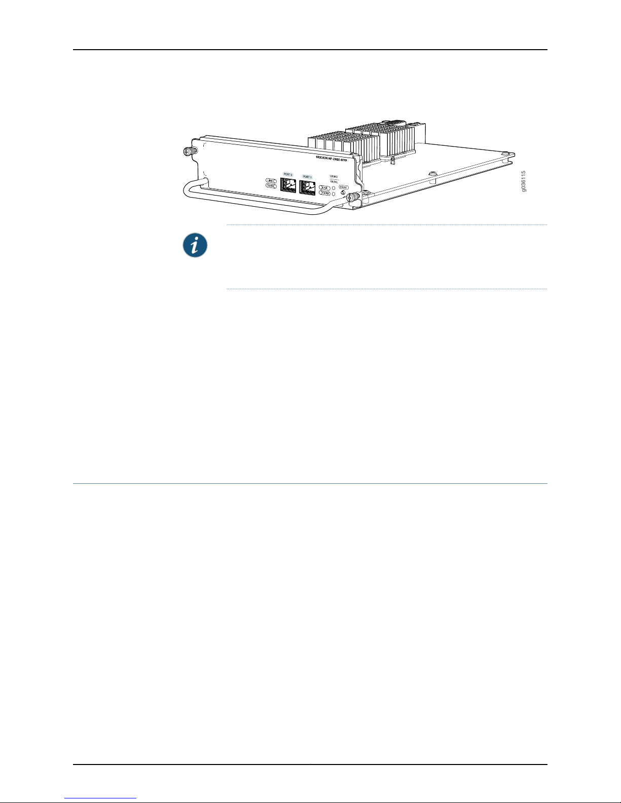
Network Processing I/O Cards (NP-IOCs) are IOCs designed specifically for low-latency
applications. Each NP-IOC has its own network processing unit (NPU), so that traffic
traversing the NP-IOC does not have to traverse the services gateway bus to a remote
network processing card (NPC).It is inserted horizontally into the midplane of the services
gateway to communicate with the Switch Fabric Board (SFB) and to receive power.
Figure 11 on page 23 shows a typical NP-IOC.
Copyright © 2013, Juniper Networks, Inc.22
Page 37
g036115
Chapter 2: SRX3400 Services Gateway Hardware Components
Figure 11: Typical NP-IOC
NOTE: You can install NP-IOCs instead of NPCs and IOCs in the services
gateway. However,if no NPCs are present, the Ethernet ports on the SFB will
not be functional.
For detailed information about the NP-IOCs supported by the services gateway, see the
SRX1400, SRX3400, and SRX3600 Services Gateway Module Guide at
www.juniper.net/techpubs/.
Related
Documentation
SRX3400 Services Gateway Chassis on page 7•
• Installing CFM Cards in the SRX3400 Services Gateway on page 59
• Available Components for the SRX3400 Services Gateway on page 9
• SRX3400 Services Gateway Switch Fabric Board on page 14
• SRX3400 Services Gateway Network Processing Cards on page 20
• SRX3400 Services Gateway Services Processing Cards on page 20
SRX3400 Services Gateway Routing Engine
The Routing Engine is a PowerPC platform that runs the Junos operating system (Junos
OS). Software processes that run on the Routing Engine maintain the routing tables,
manage the routing protocols used on theservices gateway, control the services gateway
interfaces, control some chassis components, and provide the interface for system
management and user access to the services gateway.
Two USB ports on the Routing Engine accept USB memory cards that allow you to load
Junos OS and perform file transfers.
The Routing Engine also provides the following integrated services:
•
Central Packet Forwarding Engine Processing (CPP)—This service manages all CFM
cards.
•
SystemControl—This servicehandles Routing Enginearbitration and switchingbetween
multiple control planes and acts as the host for the Switch Fabric Board (SFB) and
midplane components.
23Copyright © 2013, Juniper Networks, Inc.
Page 38
g036064
g036098
SRX3400 Services Gateway Hardware Guide
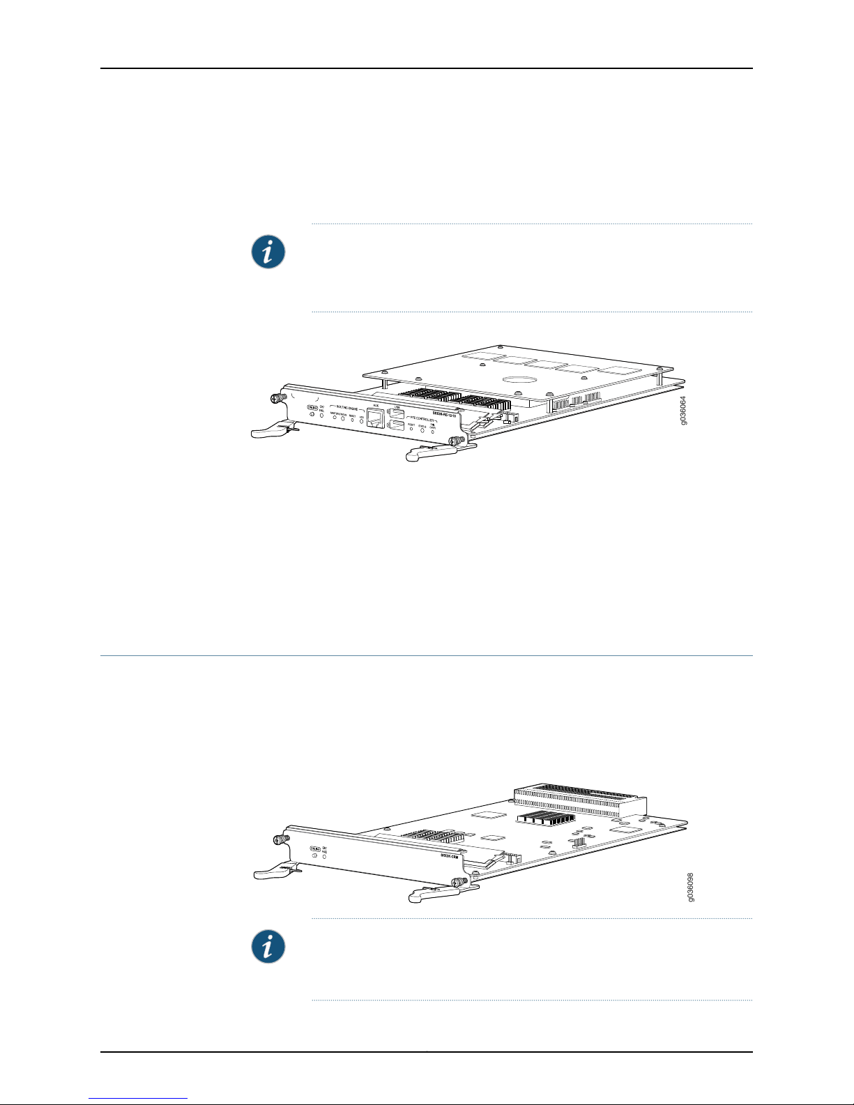
The services gateway must have one Routing Engine installed in slot RE0. A Gigabit
Ethernet port on the front panel of the Switch Fabric Board (SFB) is connected directly
to the processors on the REs for management purposes. The SFB port labeled RE
ETHERNET 0 connects to the Routing Engine in slot RE0.
Figure 12: Routing Engine
NOTE: Unless you have installed an SRX Clustering Module (SCM) in slot
RE1, the empty RE1 slot should have a blank panel installed to shield it and
to allow cooling air to circulate properly through the services gateway.
For detailed information about the Routing Engines supported by the services gateway,
see the SRX1400, SRX3400, and SRX3600 Services Gateway Module Guide at
www.juniper.net/techpubs/.
Related
Documentation
SRX3400 Services Gateway Chassis on page 7•
• Available Components for the SRX3400 Services Gateway on page 9
• Hardware Component Locations in the SRX3400 Services Gateway Chassis on page 11
SRX3400 Services Gateway SRX Clustering Module
The SRX Clustering Module (SCM) is a card that you can install in the services gateway
to enable the dual control link feature for chassis cluster supported in Junos OS Release
10.2 and later. Youinstall theSCM in the RE1 slot onthe rear panel of the services gateway.
The SCM is shown in Figure 13 on page 24.
Figure 13: SRX Clustering Module
NOTE: The services gatewaymust be running Junos OS Release 10.2 or later
touse the SCM. When running earlier Junos OS Releases,the services gateway
does not properly recognize it.
Copyright © 2013, Juniper Networks, Inc.24
Page 39

Chapter 2: SRX3400 Services Gateway Hardware Components
For more information about configuring and managing chassis clusters, see the chapter
“Chassis Cluster” in the Junos OS Security Configuration Guide.
For detailed information about the SCMs supported by the services gateway, see the
SRX1400, SRX3400, and SRX3600 Services Gateway Module Guide at
www.juniper.net/techpubs/.
Related
Installing an SRX Clustering Module in the SRX3400 Services Gateway on page 65•
Documentation
SRX3400 Services Gateway Power Supplies
The SRX3400 Services Gateway uses either one AC or one DC power supply. A second
AC or DC power supply can be used with its matching type of power supply to offer
redundancy. The power supplies connect tothe midplane,which distributes the different
output voltages produced by the power supplies to the services gateway components,
depending on their voltage requirements.
All power supplies are hot-removable and hot-insertable. Each power supply is cooled
by its own internal cooling system. The power supplies are described in the following
topics:
•
SRX3400 Services Gateway AC Power Supply Overview on page 25
•
SRX3400 Services Gateway AC Power Supply Electrical Specifications on page 26
•
SRX3400 Services Gateway DC Power Supply Overview on page 27
•
SRX3400 Services Gateway DC Power Supply Electrical Specifications on page 28
SRX3400 Services Gateway AC Power Supply Overview
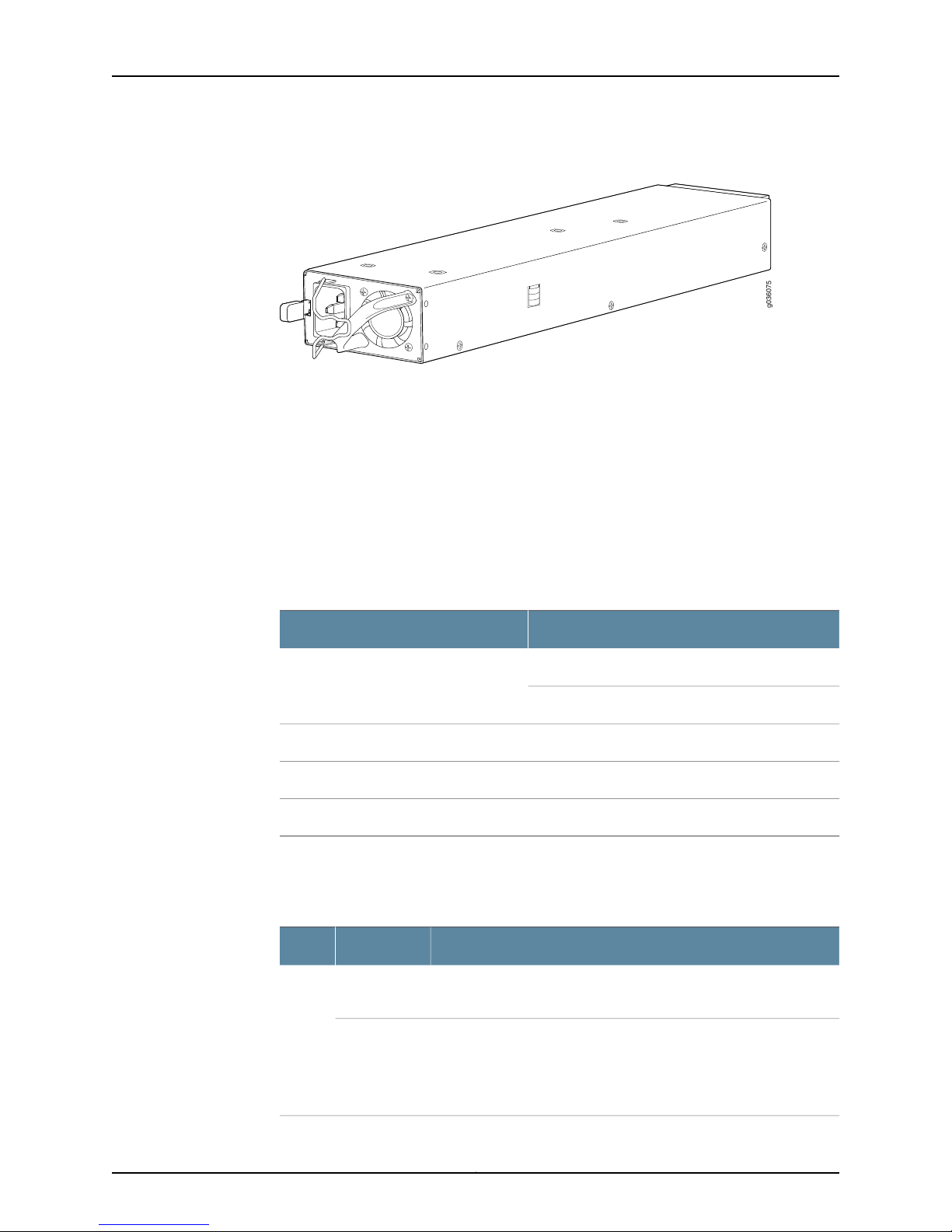
In an AC power configuration, the SRX3400 Services Gateway contains one or two AC
power supplies, located at the rear of the chassis in slots PEM0 and PEM1. Each power
supply provides power to all components in the services gateway. When two power
supplies are present, they share power almost equally within a fully populated system.
One AC power supply can meet the services gateway power requirements. Installing a
second AC power supply provides full power redundancy. If one power supply fails or is
removed, the remaining power supply assumes the electrical load without interruption.
The services gateway reassesses the power required to support its configuration and
issues errors if the available power is insufficient.
25Copyright © 2013, Juniper Networks, Inc.
Page 40
g036075
SRX3400 Services Gateway Hardware Guide
Figure 14: AC Power Supply
Related
Documentation
SRX3400 Services Gateway Chassis on page 7•
• Hardware Component Locations in the SRX3400 Services Gateway Chassis on page 11
• SRX3400 Services Gateway AC Power Supply Electrical Specifications on page 26
• Installing an AC Power Supply in the SRX3400 Services Gateway on page 66
SRX3400 Services Gateway AC Power Supply Electrical Specifications
Table 11 on page 26 lists the AC power supply electrical specifications.
Table 11: AC Power Supply Electrical Specifications
SpecificationParameter
1000 W (110 VAC input)Maximum output power
1200 W (220 VAC input)
100-127 V / 200-240 VAC input voltage
50 / 60 HzAC input line frequency
12.0 A @ 100-127 V / 7 A @ 200-240 VAC input current rating
Each AC power supply faceplate displays a single LED to indicate the status of the power
supply (see Table 12 on page 26).
Table 12: AC Power Supply LED
On steadilyGreen
Blinking
Condition IndicatedStatusColor
AC input voltage is present, and both main 12V output and standby
3.3V output are enabled and healthy.
AC input voltage is present, standby 3.3V output is on, but the main
12V outputis disabled. Thiscondition usually indicates thatthe services
gateway has been powered off at the Power button on the SFB front
panel. It might also indicate that either the SFB or the Routing Engine
has been removed from the services gateway.
Copyright © 2013, Juniper Networks, Inc.26
Page 41
Chapter 2: SRX3400 Services Gateway Hardware Components
Table 12: AC Power Supply LED (continued)
Condition IndicatedStatusColor
The power supply has detected one or more of the following faults:
•
Power supply fan failure
•
Power supply over-temperature condition
•
Over-current or under-voltage condition on the standby3.3V output
The power supply has detected one or more of the following faults:
•
Under-voltage condition on the 12V output
•
Over-voltage condition on the 12V output
•
Over-current condition on the 12V output
Related
Documentation
On steadilyAmber
Blinking
SRX3400 Services Gateway Chassis on page 7•
• Hardware Component Locations in the SRX3400 Services Gateway Chassis on page 11
• SRX3400 Services Gateway AC Power Supply Overview on page 25
SRX3400 Services Gateway DC Power Supply Overview
In a DC power configuration, the SRX3400 Services Gateway contains one or two DC
power supplies, located at the rear of the chassis in slots PEM0 and PEM1. Each power
supply provides power to all components in the services gateway. When two power
supplies are present, they share power almost equally within a fully populated system.
One DC power supply can meet the services gateway power requirements. Installing a
second DC power supply provides full power redundancy. If one power supply fails or is
removed, the remaining power supply assumes the electrical load without interruption.
The services gateway reassesses the power required to support its configuration and
issues errors if the available power is insufficient.
Two types of DC power supply are available. The standard DC power supply has a
maximum power output of 850 W. The enhanced DC power supply has a maximum
power output of 1200 W, and also has additional filters required to meet NEBS and ETSI
requirements. The two types of DC power supply are identical in all other respects.
NOTE: Mixing standard and enhanced DC power supplies within the same
chassis is not supported. All installed DC power supplies must be either of
standard or enhanced types.
27Copyright © 2013, Juniper Networks, Inc.
Page 42
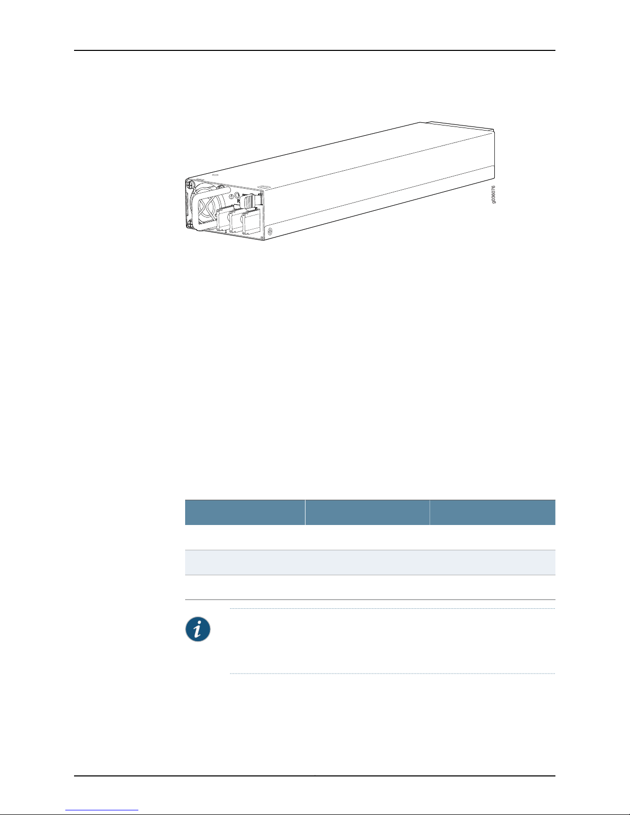
g036076
SRX3400 Services Gateway Hardware Guide
Figure 15: DC Power Supply
Related
Documentation
SRX3400 Services Gateway Chassis on page 7•
• SRX3400 Services Gateway NEBS and ETSI Compliance on page 176
• Hardware Component Locations in the SRX3400 Services Gateway Chassis on page 11
• SRX3400 Services Gateway DC Power Supply Electrical Specifications on page 28
• Installing a DC Power Supply in the SRX3400 Services Gateway on page 69
SRX3400 Services Gateway DC Power Supply Electrical Specifications
Two types of DC power supply are available. The standard DC power supply has a
maximum power output of 850 W. The enhanced DC power supply has a maximum
power output of 1200 W, and also has additional filters required to meet NEBS and ETSI
requirements. The two types of DC power supply are identical in all other respects. Each
DC power supply has a single DC input (-48 VDC and return) that requires a dedicated
40 A (-48 VDC) circuit breaker. Table 13 on page 28 lists the DC power supply electrical
specifications.
Table 13: DC Power Supply Electrical Specifications
Enhanced DC Power SupplyStandard DC Power SupplyItem
1200 W850 WMaximum output power
Each DC power supply faceplate displays a singleLED to indicate the status of the power
supply (see Table 14 on page 29).
–40.5 to –72 VDC–40.5 to –72 VDCDC input voltage
31.3 A @ -48 VDC22.2 A @ -48 VDCDC input current rating
NOTE: Mixing standard and enhanced DC power supplies within the same
chassis is not supported. All installed DC power supplies must be either of
standard or enhanced types.
Copyright © 2013, Juniper Networks, Inc.28
Page 43

Table 14: DC Power Supply LED
Indicated ConditionLED StatusColor
Chapter 2: SRX3400 Services Gateway Hardware Components
On steadilyGreen
Blinking
On steadilyRed
Blinking
Related
Documentation
DC input voltage is present, and both main 12V output and standby 3.3V output are enabled
and healthy.
DC input voltage is present, standby 3.3V output is on, but the main 12V output is disabled.
This conditionusually indicates thatthe servicesgateway has been poweredoff at the Power
button onthe SFB front panel. It might also indicate that either the SFB or theRouting Engine
has been removed from the services gateway.
The power supply has detected one or more of the following faults:
•
Power supply fan failure
•
Power supply over-temperature condition
•
Over-current or under-voltage condition on the standby 3.3V output
The power supply has detected one or more of the following faults:
•
Under-voltage condition on the 12V output
•
Over-voltage condition on the 12V output
•
Over-current condition on the 12V output
SRX3400 Services Gateway Chassis on page 7•
• Hardware Component Locations in the SRX3400 Services Gateway Chassis on page 11
• SRX3400 Services Gateway DC Power Supply Overview on page 27
SRX3400 Services Gateway Fan Tray
The cooling system consists of a fan tray containing four fans and an air filter. These
components work together to keep all services gateway components within the
acceptable temperature range. The SRX3400 Services Gateway has one fan traylocated
in the rear of the services gateway that installs vertically to the right of the card cage.
The fan tray is hot-insertable and hot-removable.
29Copyright © 2013, Juniper Networks, Inc.
Page 44
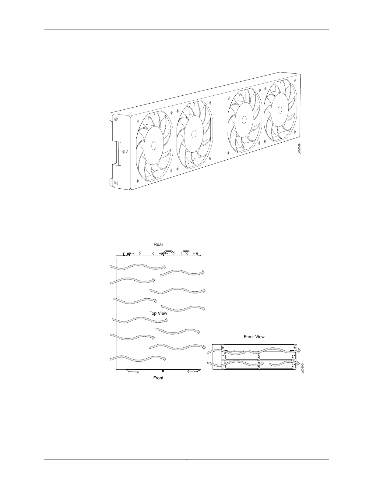
g036069
g036004
Top View
Front View
Front
Rear
SRX3400 Services Gateway Hardware Guide
Figure 16: Fan Tray
From the front of the chassis, there is a single air intake on the left side of the services
gateway. Air is pushed from the fan tray through the air filter and then to the card cage.
The air is exhausted out the right of the system. Figure 17 on page 30 illustrates the air
flow from the top of the chassis and the front of the chassis.
Figure 17: Airflow Through the Chassis
At startup, the Routing Engine runs the fans at full speed until it can obtain reliable
temperature data from its temperature sensors. After it finishes booting and has reliable
temperature data,the Routing Engine monitors thetemperature of certain criticalservices
gateway components and adjusts the speed of the fans accordingly.
The fans have three speeds: low, intermediate, and high. Table 15 on page 31 shows the
correlations between fan speed and critical component temperature. Note that there is
Copyright © 2013, Juniper Networks, Inc.30
Page 45

Chapter 2: SRX3400 Services Gateway Hardware Components
hysteresis built into the correlation, so that the fans are not subject to spurious speed
changes. Also, if one of the fans in the fan tray fails, the speeds of the remaining fans are
automatically adjusted to keep the temperature within the acceptable range.
Table 15: Critical Component Temperatures and Fan Speed Transitions
Fan Speed ResponseCritical Component Temperature
Increase from Low to MediumIncrease to 60°C
Increase from Medium to HighIncrease to 75°C
Decrease from High to MediumDecrease to 65°C
Decrease from Medium to LowDecrease to 55°C
If the maximum internal temperature specification is exceeded and the system cannot
be adequately cooled, the Routing Engine shuts down the system by disabling output
power from each power supply.
Related
Documentation
SRX3400 Services Gateway Chassis on page 7•
• Hardware Component Locations in the SRX3400 Services Gateway Chassis on page 11
• Available Components for the SRX3400 Services Gateway on page 9
• Replacing the Fan Tray on the SRX3400 Services Gateway on page 112
SRX3400 and SRX5600 Services Gateways Air Deflector Kits
Optional air deflector kits are available that let you install the SRX3400 and SRX5600
Services Gateways in a hot aisle/cold aisle ventilation environment. These kits convert
the services gateway from side-to-side ventilation into front-to-back ventilation. The air
deflectors contain no additional fans, so they require no additional electrical power. Air
deflector kits are not available for the SRX3600 Services Gateway.
For more information about the hot aisle/cold aisle air deflector kits, send an e-mail to
The air deflector kits consist of four main components: two intake/exhaust boxes and
two side plenums. The two intake/exhaust boxes are identical to each other, as are the
side plenums.
The intake/exhaust boxes are installed above and below the services gateway to direct
intake air from the air space in front of the services gateway intothe side plenum mounted
on theintake sideof the device. The intake air plenum directsair intothe services gateway,
and the exhaust air plenum collects the exhaust air on the opposite side of the device.
The exhaust plenum directs the exhausted air into the intake/exhaust boxes above and
below the unit, where it is expelled into the air space behind the services gateway.
The air deflector kit requires additional space around the services gateway, increasing
its overall height and width as described in Table 16 on page 32.
31Copyright © 2013, Juniper Networks, Inc.
Page 46
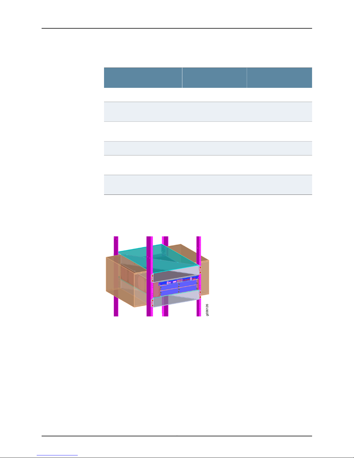
g036126
SRX3400 Services Gateway Hardware Guide
Table 16: Services Gateway and Air Deflector Dimensions
SRX5600 Services
Gateway
8 U (14 in. or 35.6 cm)3 U (5.25 in. or 13.3 cm)Services gateway height
6 U (10.5 in. or 26.7 cm)4 U (7 in. or 17.8 cm)Additional height required for air
14 U (24.5 in. or 62.2 cm)7 U (12.25 in. or 31.1 cm)Total height of services gateway
17.5 in. (44.5 cm)17.5 in. (44.5 cm)Services gateway chassis width
5.6 in. (14.2 cm) per side
11.2 in. (28.4 cm) total
28.7 in. (72.9 cm)28.7 in. (72.9 cm)Total width of services gateway
deflector kit
and air deflector kit
Additional width required for air
deflector kit
and air deflector kit
SRX3400 Services
GatewaySpecification
5.6 in. (14.2 cm) per side
11.2 in. (28.4 cm) total
Figure 18 on page 32and Figure 19on page 33show theSRX3400 andSRX5600 Services
Gateways, respectively, installed intypicalfour-post mounting rackswith the air deflector
kit parts in place.
Figure 18: SRX3400 Services Gateway Air Deflector Kit
Copyright © 2013, Juniper Networks, Inc.32
Page 47
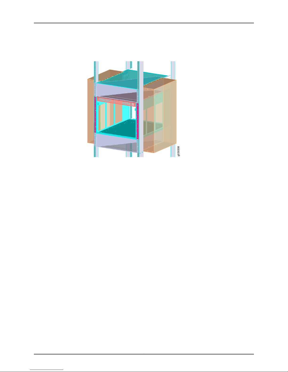
g030308
Chapter 2: SRX3400 Services Gateway Hardware Components
Figure 19: SRX5600 Services Gateway Air DeflectorKit (Services Gateway
Chassis Contents Omitted for Clarity)
Related
Documentation
• SRX3400 Services Gateway Chassis on page 7
• SRX5600 Services Gateway Chassis
33Copyright © 2013, Juniper Networks, Inc.
Page 48

SRX3400 Services Gateway Hardware Guide
Copyright © 2013, Juniper Networks, Inc.34
Page 49

PART 2
Setting Up the SRX3400 Services
Gateway
•
Preparing the Site for SRX3400 Services Gateway Installation on page 37
•
Unpacking the SRX3400 Services Gateway on page 45
•
Installing the SRX3400 Services Gateway on page 49
•
Installing Additional Components in the SRX3400 Services Gateway on page 59
•
Connecting the SRX3400 Services Gateway on page 71
•
Grounding and Providing Power to the SRX3400 Services Gateway on page 75
•
PerformingInitial Software Configuration on the SRX3400 ServicesGateway onpage 85
35Copyright © 2013, Juniper Networks, Inc.
Page 50

SRX3400 Services Gateway Hardware Guide
Copyright © 2013, Juniper Networks, Inc.36
Page 51
CHAPTER 3
Preparing the Site for SRX3400 Services
Gateway Installation
This section includes the following topics:
•
Site Preparation Checklist for the SRX3400 Services Gateway on page 37
•
SRX3400 Services Gateway Cabinet Requirements on page 38
•
SRX3400 Services Gateway Rack Requirements on page 39
•
Clearance Requirements for Airflow and Hardware Maintenance of the SRX3400
Services Gateway on page 42
Site Preparation Checklist for the SRX3400 Services Gateway
The checklist in Table 17 on page 37 summarizes the tasks you need to perform when
preparing a site for SRX3400 Services Gateway installation.
Table 17: Site Preparation Checklist
Verify that environmental factors such as
temperature and humidity do not exceed
Services Gateway tolerances.
Select the type of rack or cabinet.
Plan rack or cabinet location, including required
space clearances.
If a rack is used, secure rack to floor and
building structure.
Acquire cables and connectors.
Locate sites for connection of system
grounding.
“SRX3400 Services Gateway Environmental
Specifications” on page 179
“SRX3400 Services Gateway Cabinet Size and
Clearance Requirements” on page 38 and “SRX3400
Services Gateway Rack Size and Strength
Requirements” on page 40
“SRX3400 Services Gateway Cabinet Airflow
Requirements” on page 39
“Connecting the SRX3400 Services Gateway to the
Building Structure” on page 42
“DC Power Electrical Safety Guidelines and Warnings”
on page 168
Performed
ByFor More Information ...Item or Task
Date
37Copyright © 2013, Juniper Networks, Inc.
Page 52
SRX3400 Services Gateway Hardware Guide
Table 17: Site Preparation Checklist (continued)
Measure distance between external power
sources and services gateway installation site.
Performed
ByFor More Information ...Item or Task
Date
Calculate theoptical power budgetand optical
power margin.
Related
Documentation
Installation Overview for the SRX3400 Services Gateway on page 49•
• Unpacking the SRX3400 Services Gateway on page 45
“Calculating the Power Budget for Fiber-Optic Cable
for the SRX3400 Services Gateway” on page 198 and
“Calculating the Power Margin for Fiber-Optic Cable
for the SRX3400 Services Gateway” on page 198
SRX3400 Services Gateway Cabinet Requirements
The services gateway can be installed in an enclosed cabinet. The cabinet requirements
are described in the following topics:
•
SRX3400 Services Gateway Cabinet Size and Clearance Requirements on page 38
•
SRX3400 Services Gateway Cabinet Airflow Requirements on page 39
SRX3400 Services Gateway Cabinet Size and Clearance Requirements
The minimum size cabinet that can accommodate the services gateway is 27.5 in.
(69.8 cm) wide and 31.5 in. (80.0 cm) deep. The cabinet must allow at least 5 in. (13
cm) of clearance on each side of the chassis to allow for cooling air to flow through the
vents on eachside ofthe device. Acabinet larger than theminimum requirement provides
better airflow and reduces the chance of overheating.
Allow at least 3 in. (7.6 cm) of vertical clearance between the top and bottom of the
services gateway and other devices in the cabinet.
The minimum front and rear clearance requirements depend on the mounting
configuration you choose. The minimum total clearance inside the cabinet is 30.7 in.
(78 cm) between the inside of the front door and the inside of the rear door.
The device has not been tested for NEBS and ETSI compliance when mounted inside an
enclosed cabinet. NEBS certification only applies if the device is mounted in a two-post
or four-post rack.
Related
Documentation
SRX3400 Services Gateway Cabinet Airflow Requirements on page 39•
• SRX3400 Services Gateway Rack Size and Strength Requirements on page 40
• SRX3400 Services Gateway Spacing of Mounting Bracket Holes on page 41
• Clearance Requirements for Airflow and Hardware Maintenance of the SRX3400
Services Gateway on page 42
Copyright © 2013, Juniper Networks, Inc.38
Page 53

Chapter 3: Preparing the Site for SRX3400 Services Gateway Installation
• SRX3400 Services Gateway NEBS and ETSI Compliance on page 176
SRX3400 Services Gateway Cabinet Airflow Requirements
When you mount the services gateway in a cabinet, you must ensure that ventilation
through the cabinetis sufficientto prevent overheating. Following isa list of requirements
to consider when planning for chassis cooling:
•
Ensure that thecool airsupply you provide throughthe cabinetcan adequatelydissipate
the thermal output of the services gateway.
•
Allow at least 3 in. (7.6 cm) of vertical clearance between the top and bottom of the
services gateway and other devices in the cabinet.
•
Ensure that the cabinet allows the chassis hot exhaust air to exit from the cabinet
without recirculating into the services gateway. An open cabinet (without a top or
doors) that employs hot air exhaust extraction from the top allows the best airflow
through the chassis.
•
Ensure that the cabinet provides at least 13 cm (5 in) of clearance on each side of the
chassis for cooling airflow.
•
If the cabinet contains a top or doors, you must provide perforations in these elements
to allow adequate airflow through the cabinet to dissipate the heat generated by all
of the devices in the cabinet.
•
Route and dress all cables to minimize the blockage of airflow to and from the chassis.
Related
Documentation
SRX3400 Services Gateway Environmental Specifications on page 179•
• Clearance Requirements for Airflow and Hardware Maintenance of the SRX3400
Services Gateway on page 42
• SRX3400 Services Gateway Cabinet Size and Clearance Requirements on page 38
• SRX3400 Services Gateway Rack Size and Strength Requirements on page 40
• SRX3400 Services Gateway Spacing of Mounting Bracket Holes on page 41
SRX3400 Services Gateway Rack Requirements
The SRX3400 Services Gateway can be installed in a rack. Many types of racks are
acceptable, includingfour-post (telco)racks and open-frameracks. The rack requirements
are described in the following topics:
•
SRX3400 Services Gateway Rack Size and Strength Requirements on page 40
•
SRX3400 Services Gateway Spacing of Mounting Bracket Holes on page 41
•
Connecting the SRX3400 Services Gateway to the Building Structure on page 42
39Copyright © 2013, Juniper Networks, Inc.
Page 54

SRX3400 Services Gateway Hardware Guide
SRX3400 Services Gateway Rack Size and Strength Requirements
The services gateway is designed for installation into a 19 in. rack as defined in Cabinets,
Racks, Panels, and Associated Equipment (document number EIA-310–D) published by
the electronics Industry Association (http://www.eia.org).
With the use of adapters, the services gateway is designed to fit into a 600-mm-wide
rack or cabinet, as defined in the four-part Equipment Engineering (EE); European
telecommunications standard for equipment practice (document numbers ETS 300 119-1
through 119-4) published by the European Telecommunications Standards Institute
(http://www.etsi.org). Use approved wing devices to narrow the opening between the
rails.
The rack rails must be spaced widely enough to accommodate the services gateway
chassis's external dimensions: 5.25 in. (13.3 cm) high, 25.5 in. (64.8 cm) deep, and
17.5 in. (44.5 cm) wide. The spacing of rails and adjacent racks must also allow for the
clearances around the services gateway and rack.
The chassis height of 5.25 in. (13.3 cm) is approximately 3 U. A U is the standard rack unit
defined in Cabinets, Racks, Panels, and Associated Equipment (document number
EIA-310-D) published by the Electronics Industry Association. You can stack eight
SRX3400 Services Gateways in a rack that has at least 40 U (70 in. or 1.78 m) of usable
vertical space.
The rack must be strong enough to support the weight of the fully configured services
gateway, up to 77 lb (35 kg). If you stack eight fully configured services gateways in one
rack, it must be capable of supporting up to 616 lb (280 kg).
Copyright © 2013, Juniper Networks, Inc.40
Page 55
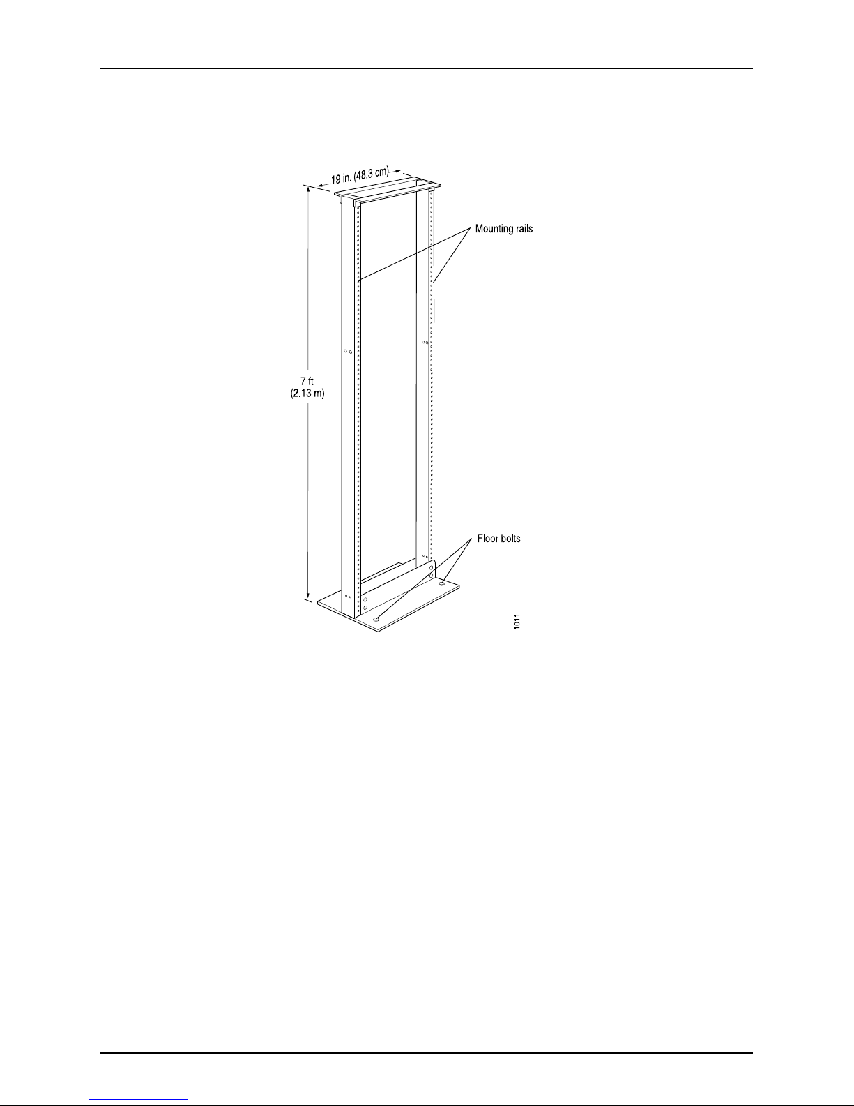
Chapter 3: Preparing the Site for SRX3400 Services Gateway Installation
Figure 20: Typical Open-Frame Rack
Related
Documentation
SRX3400 Services Gateway Spacing of Mounting Bracket Holes on page 41•
• Clearance Requirements for Airflow and Hardware Maintenance of the SRX3400
Services Gateway on page 42
• Connecting the SRX3400 Services Gateway to the Building Structure on page 42
SRX3400 Services Gateway Spacing of Mounting Bracket Holes
The services gateway can be mounted in any rack that provides holes or hole patterns
spaced at 1 U (1.75 in.) increments. The mounting brackets used to attach the chassis to
a rack are designed to fasten to holes spaced at those distances.
Related
Documentation
SRX3400 Services Gateway Rack Size and Strength Requirements on page 40•
• Clearance Requirements for Airflow and Hardware Maintenance of the SRX3400
Services Gateway on page 42
• Connecting the SRX3400 Services Gateway to the Building Structure on page 42
41Copyright © 2013, Juniper Networks, Inc.
Page 56

SRX3400 Services Gateway Hardware Guide
Connecting the SRX3400 Services Gateway to the Building Structure
Always securethe rackto thestructure of the building. If your geographical area is subject
to earthquakes, bolt the rack to the floor. For maximum stability, also secure the rack to
ceiling brackets.
Related
Documentation
Rack-Mounting Requirements and Warnings on page 149•
• SRX3400 Services Gateway Rack Size and Strength Requirements on page 40
• Clearance Requirements for Airflow and Hardware Maintenance of the SRX3400
Services Gateway on page 42
• SRX3400 Services Gateway Spacing of Mounting Bracket Holes on page 41
Clearance Requirements for Airflow and Hardware Maintenance of the SRX3400
Services Gateway
When planning the installation site, you need to allow sufficient clearance around the
rack (see Figure 21 on page 43):
•
For the cooling system to function properly, the airflow around the chassis must be
unrestricted. Allow at least 6 in. (15.2 cm) of clearance between services gateways.
Allow5 in. (13 cm) between theside ofthe chassisand anynon-heat-producing surface
such as a wall.
•
For service personnel to remove and install hardware components, there must be
adequate space at the front and back of the services gateway. At least 24 in. (61 cm)
is required both in front of and behind the services gateway. NEBS GR-63 recommends
that you allow at least 30 in. (76 cm) in front of the rack and 24 in. (61 cm) behind the
rack.
Copyright © 2013, Juniper Networks, Inc.42
Page 57
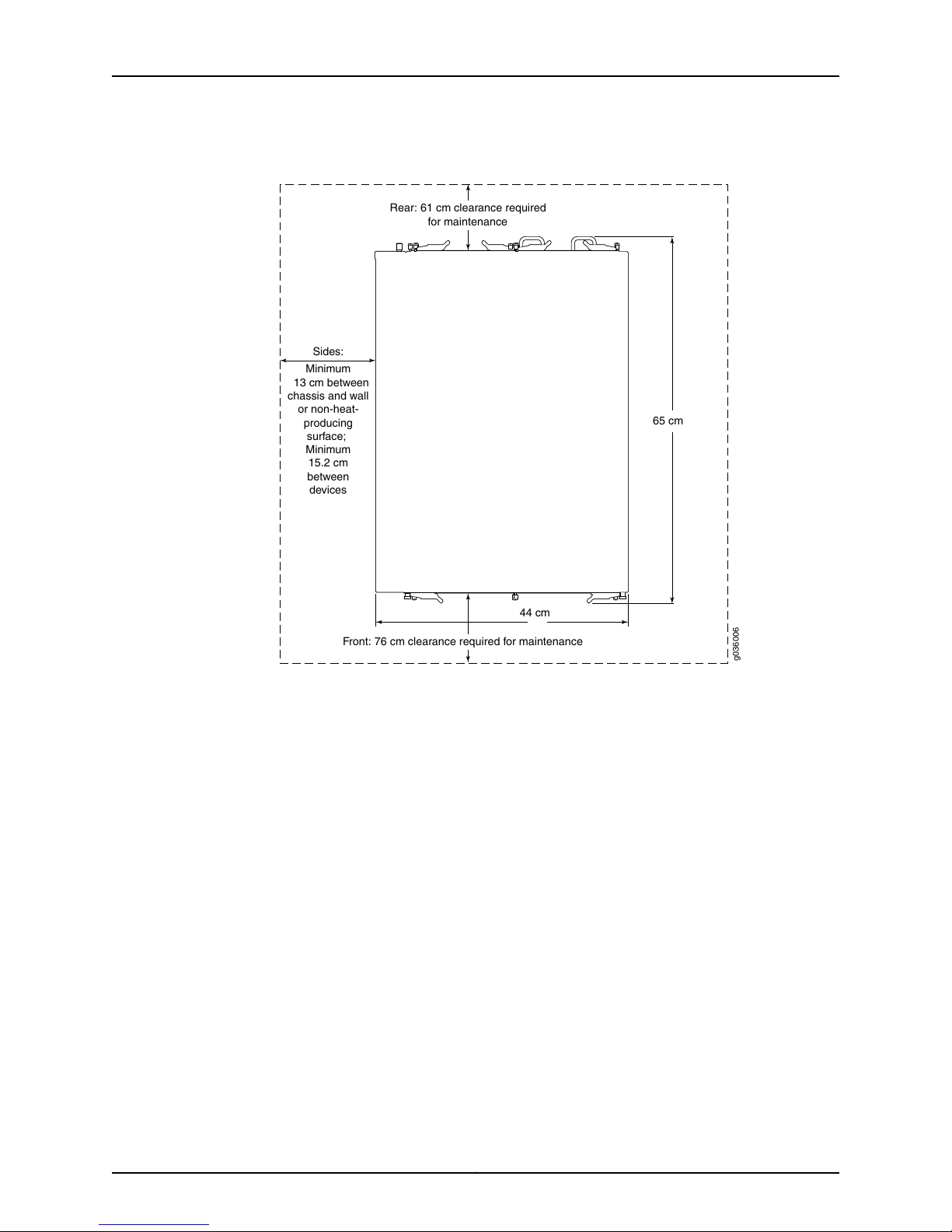
g036006
65 cm
Front: 76 cm clearance required for maintenance
44 cm
Minimum
13 cm between
chassis and wall
or non-heat-
producing
surface;
Minimum
15.2 cm
between
devices
Sides:
Rear: 61 cm clearance required
for maintenance
Chapter 3: Preparing the Site for SRX3400 Services Gateway Installation
Figure 21: Clearance Requirements
Related
Documentation
• SRX3400 Services Gateway Rack Size and Strength Requirements on page 40
• Connecting the SRX3400 Services Gateway to the Building Structure on page 42
• SRX3400 Services Gateway Spacing of Mounting Bracket Holes on page 41
43Copyright © 2013, Juniper Networks, Inc.
Page 58

SRX3400 Services Gateway Hardware Guide
Copyright © 2013, Juniper Networks, Inc.44
Page 59

CHAPTER 4
Unpacking the SRX3400 Services
Gateway
This section includes the following topics:
•
Required Tools and Parts for Unpacking the SRX3400 Services Gateway on page 45
•
Unpacking the SRX3400 Services Gateway on page 45
•
Verifying Parts Received with the SRX3400 Services Gateway on page 47
Required Tools and Parts for Unpacking the SRX3400 Services Gateway
To unpack the SRX3400 Services Gateway and prepare for installation, you need the
following tools:
•
Phillips (+) screwdriver, number 2
•
Blank panels to cover any slots not occupied by a component
Related
Documentation
Unpacking the SRX3400 Services Gateway on page 45•
• Verifying Parts Received with the SRX3400 Services Gateway on page 47
Unpacking the SRX3400 Services Gateway
The services gateway is shipped in a cardboard carton. The SRX3400 Services Gateway
Getting Started Guide and an accessory box are also included in the shipping carton.
The shipping container measures 11 in. (28 cm) high, 24.1 in. (61 cm) wide, and
33.6 in. (85 cm) deep.The system and its packaging have atotal weight of62 lb(42.2 kg).
NOTE: The services gateway is maximally protected inside the shipping
carton. Do not unpack it until you are ready to begin installation.
45Copyright © 2013, Juniper Networks, Inc.
Page 60
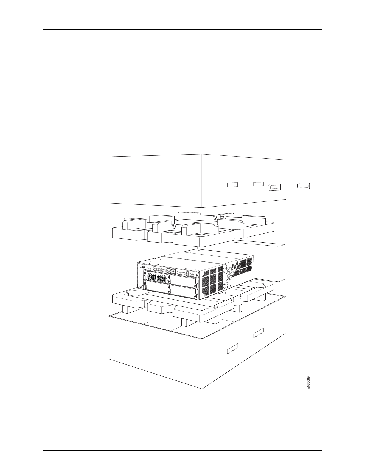
98
0630g
SRX3400 Services Gateway Hardware Guide
To unpack the services gateway:
1. Move the shipping carton to a staging area as close to the installation site as possible,
where you have enough room to remove the components from the chassis.
2. Position the shipping carton with the arrows pointing up.
3. Remove theplastic handle insertsand liftthe cardboard cover offthe servicesgateway.
4. Remove the foam covering the top of the services gateway.
5. Remove the accessory box, the mounting shelf, and the SRX3400 Services Gateway
Getting Started Guide.
Figure 22: Unpacking the SRX3400 Services Gateway
6. With a person on each side of the carton, carefully lift the services gateway from the
carton and place on lift. Remove the bag covering the services gateway.
7. Verify the parts received against thelists in “Verifying Parts Received with the SRX3400
Services Gateway” on page 47.
Copyright © 2013, Juniper Networks, Inc.46
Page 61
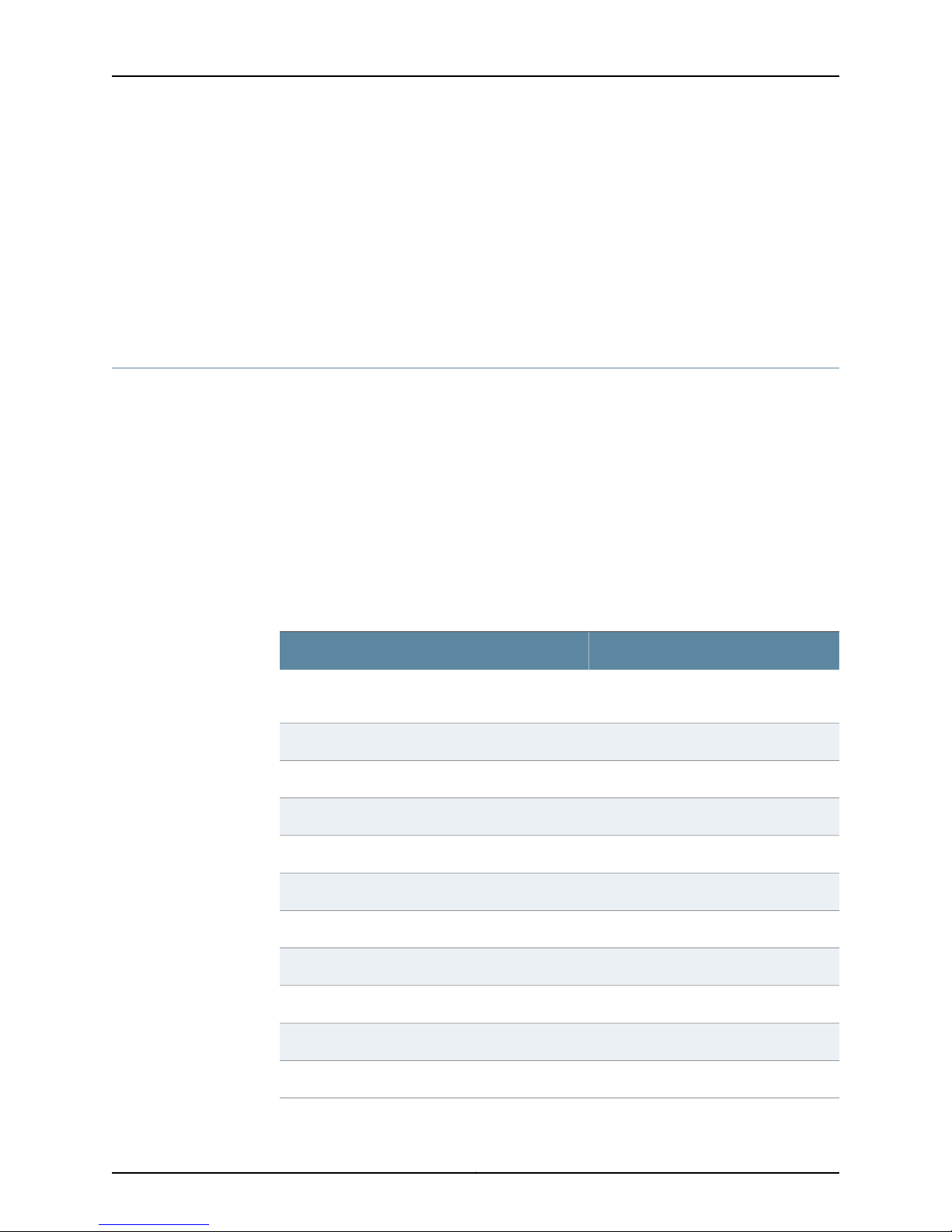
Chapter 4: Unpacking the SRX3400 Services Gateway
8. Save the shipping carton and packing materials in case you need to move or ship the
services gateway at a later time.
9. To proceed with the installation, see “Installing the SRX3400 Services Gateway in a
Rack or Cabinet Using a Mechanical Lift” on page 53.
Related
Documentation
Required Tools and Parts for Unpacking the SRX3400 Services Gateway on page 45•
• Verifying Parts Received with the SRX3400 Services Gateway on page 47
Verifying Parts Received with the SRX3400 Services Gateway
A packing list is included in each shipment. Check the parts in the shipment against the
items on the packing list. The packing list specifies the part numbers and descriptions of
each part in your order. Note that feature and service cards are shipped in separate boxes
from the chassis.
If any part is missing, contact a customer service representative.
A fully configured services gateway contains the chassis with installed components,
listed in Table 18 on page 47, and an accessory box, which contains the parts listed in
Table 19 on page 48. The parts shipped with your services gateway can vary depending
on the configuration you ordered.
Table 18: Parts List for a Fully Configured SRX3400 Services Gateway
QuantityComponent
1Chassis, including midplane, and rack-mounting
brackets
Up to 4IOCs
Up to 6NP-IOCs
At least one, and up to 4SPCs
At least one, and up to 2NPCs
1Routing Engine
0 or 1SCM
1SFB
At least 1 and up to 2Power supplies
1Fan tray
1Air filter
47Copyright © 2013, Juniper Networks, Inc.
Page 62
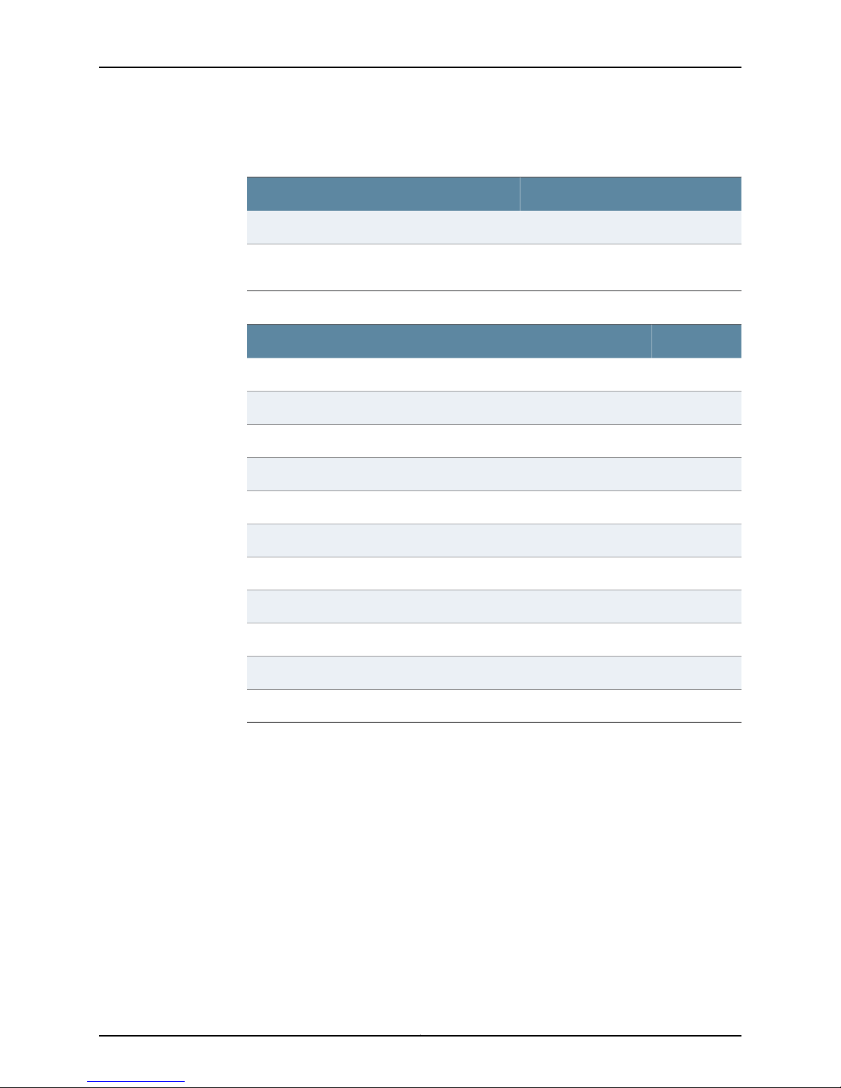
SRX3400 Services Gateway Hardware Guide
Table 18: Parts List for a Fully Configured SRX3400 Services
Gateway (continued)
QuantityComponent
1SRX3400 Services Gateway Getting Started Guide
Blank panelsfor slots without componentsinstalled
Table 19: Accessory Box Parts List
One blankpanel for each slotnot occupied
by a component
QuantityPart
1Rack mount kit
1RJ-45-to-DB-9 cable to connect the services gateway through the serial port
1Juniper Networks Product Warranty
1End User License Agreement
1SRX3400 Services Gateway Getting Started Guide
1Documentation Information Card
1Product Registration
1Juniper Compliance Form Letter; RoHS
1Declaration of Conformity
Related
Documentation
1Document sleeve
1ESD wrist strap with cable
• Required Tools and Parts for Unpacking the SRX3400 Services Gateway on page 45
• Unpacking the SRX3400 Services Gateway on page 45
Copyright © 2013, Juniper Networks, Inc.48
Page 63

CHAPTER 5
Installing the SRX3400 Services Gateway
This section provides instructions for installing the services gateway in a rack or cabinet.
Because of the size and weight of the services gateway—up to 77 lb (35 kg) depending
on the configuration—we strongly recommend that you install it using a mechanical lift.
The services gateway should not be installed in a front-mounted position.
This section includes the following topics:
•
Installation Overview for the SRX3400 Services Gateway on page 49
•
SRX3400 Services GatewaySafetyRequirements,Warnings, and Guidelines onpage 50
•
Required Tools for Installing the SRX3400 Services Gateway on page 50
•
Preparing the SRX3400 Services Gateway for Rack-Mount or Cabinet
Installation on page 51
•
Installing the Mounting Hardware for the SRX3400 Services Gateway on page 51
•
Installing the SRX3400 Services Gateway in a Rack or Cabinet Using a Mechanical
Lift on page 53
•
Installing the SRX3400 Services Gateway in a Rack or Cabinet Without a Mechanical
Lift on page 55
Installation Overview for the SRX3400 Services Gateway
After you have prepared your installation site, as described in “Site Preparation Checklist
for the SRX3400 Services Gateway” on page 37, you are ready to unpack and install the
services gateway. It is important to proceed through the installation process in the
following order:
1. Review the safety guidelines explained in “SRX3400 Services Gateway Definition of
Safety Warning Levels” on page 139.
2. Install the services gateway, as described in “Installing the SRX3400 ServicesGateway
in a Rack or Cabinet Using a Mechanical Lift” on page 53.
3. Connect cables toexternal devices, as describedin “Connecting the SRX3400 Services
Gateway to a Management Console or an Auxiliary Device” on page 72 or “Connecting
the SRX3400 Services Gateway to a Network for Out-of-Band Management” on
page 72.
49Copyright © 2013, Juniper Networks, Inc.
Page 64

SRX3400 Services Gateway Hardware Guide
4. Connect the grounding cable, as described in “Grounding the SRX3400 Services
Gateway” on page 76.
5. Connect thepower cables, as describedin “Connecting theSRX3400 Services Gateway
to a DC Power Source” on page 79 or “Connecting the SRX3400 Services Gateway
to an AC Power Source” on page 77.
6. Power on the services gateway, as described in “Powering On the SRX3400 Services
Gateway” on page 81.
7. Perform the initial system startup, as described in “Performing Initial Software
Configuration on the SRX3400 Services Gateway” on page 86.
Related
Documentation
SRX3400 Services Gateway Chassis on page 7•
• Routine Maintenance Procedures for the SRX3400 Services Gateway on page 94
SRX3400 Services Gateway Safety Requirements, Warnings, and Guidelines
To avoid harm to yourself or the services gateway as you install and maintain it, follow
the guidelines for working with and near electrical equipment, as well as the safety
procedures for working with networking devices. However, providing an exhaustive set
of guidelines for working with electrical equipment is beyond the scope of this guide.
Related
Documentation
Site Preparation Checklist for the SRX3400 Services Gateway on page 37•
• SRX3400 Services Gateway Definition of Safety Warning Levels on page 139
• General Electrical Safety Guidelines and Warnings on page 163
Required Tools for Installing the SRX3400 Services Gateway
To install the services gateway, you need the following tools:
•
Mechanical lift
•
Phillips (+) screwdriver, number 2
Related
Documentation
Preparing the SRX3400 Services Gateway for Rack-Mount or Cabinet Installation on
•
page 51
• Installing the Mounting Hardware for the SRX3400 Services Gateway on page 51
• Installing the SRX3400 Services Gateway in a Rack or Cabinet Using a Mechanical Lift
on page 53
Copyright © 2013, Juniper Networks, Inc.50
Page 65

Chapter 5: Installing the SRX3400 Services Gateway
Preparing the SRX3400 Services Gateway for Rack-Mount or Cabinet Installation
Before you begin the installation, verify the following:
•
Your site has been properly prepared for the services gateway. See “Site Preparation
Checklist for the SRX3400 Services Gateway” on page 37 for a summary of the tasks
you need to perform.
•
The services gateway has been removed from the shipping container. See “Unpacking
the SRX3400 Services Gateway” on page 45.
•
You have read the safety information in “Chassis Lifting Guidelines” on page 148.
•
Ensure the rack is in its permanent location and is secured to the building. Ensure that
the installation site allows adequate clearance for both airflow and maintenance. For
details, see “Clearance Requirements for Airflow and Hardware Maintenance of the
SRX3400 Services Gateway” on page 42.
Related
Documentation
SRX3400 Services Gateway Definition of Safety Warning Levels on page 139•
• Installing the Mounting Hardware for the SRX3400 Services Gateway on page 51
• Installing the SRX3400 Services Gateway in a Rack or Cabinet Using a Mechanical Lift
on page 53
Installing the Mounting Hardware for the SRX3400 Services Gateway
The specific mounting hardware used depends on the type of rack being utilized. Use the
appropriate procedure steps to install the mounting hardware for your situation.
To install the mounting hardware:
1. Locate the rack mount brackets in the accessory kit.
2. Use the screws provided to secure the rack mount brackets to the sides of the chassis:
•
For a two-post rack, mount the brackets at the mid-mount holes, as shown in
Figure 23 on page 52.
WARNING: When you install the services gateway in a two-post rack,
you must attach the mounting brackets at the middle of each chassis
side, as shown in Figure 23 on page 52. Do not attempt to install the
servicesgatewayina two-postrack with the mounting brackets attached
at the front of the chassis. Such an installation might overstress either
the brackets or the rack, causing the chassis to fall and inflict injury.
51Copyright © 2013, Juniper Networks, Inc.
Page 66
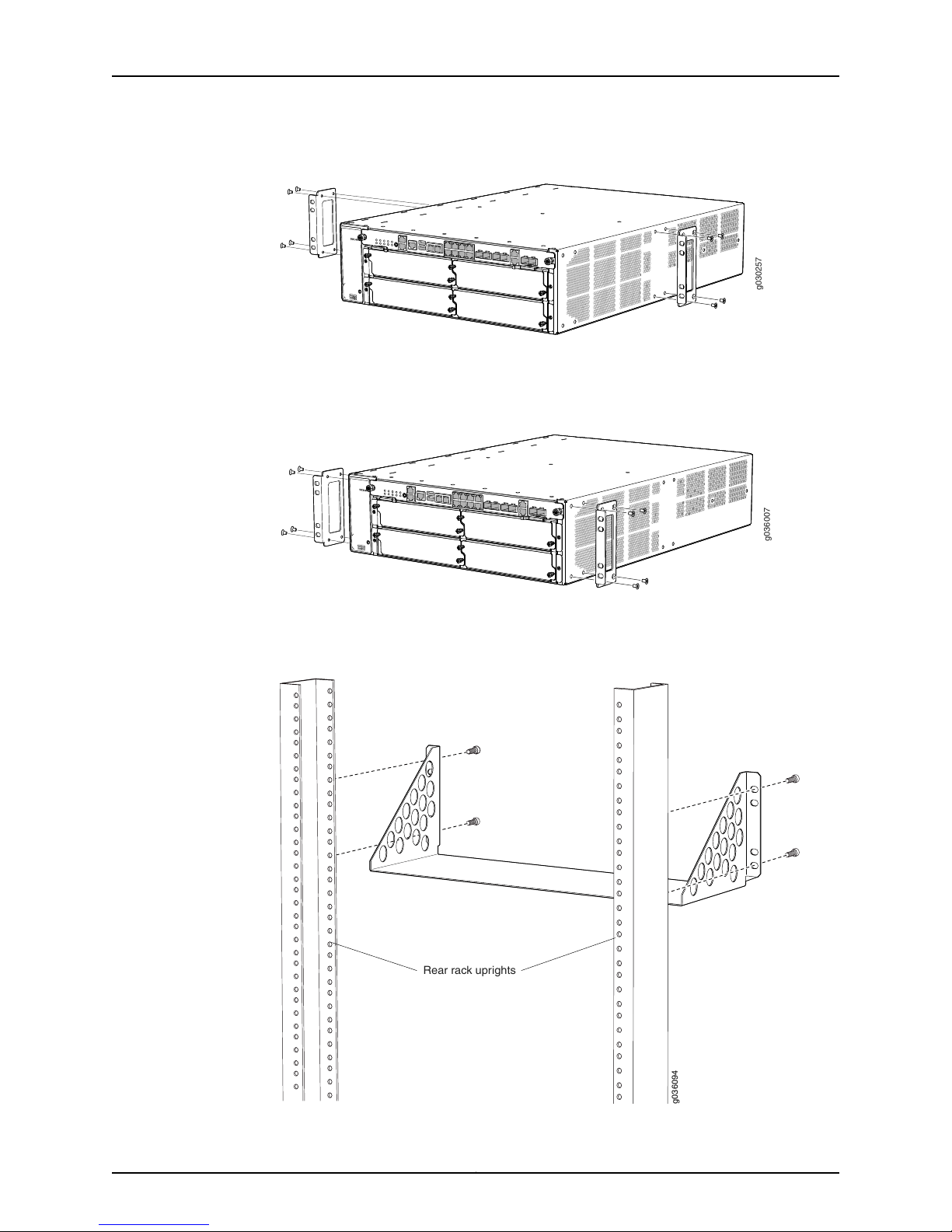
g030257
0
1
2
3
4
g036007
Rear rack uprights
g036094
SRX3400 Services Gateway Hardware Guide
Figure 23: Attaching Mounting Hardware for Two-Post Rack
•
For afour-post rack, mountthe brackets nearthe front edgeof the chassis, asshown
in Figure 24 on page 52.
Figure 24: Attaching Mounting Hardware for Cabinet or Four-Post Rack
3. For installation in a cabinet or a four-post rack, install the support shelf on the rear
posts, as shown in Figure 25 on page 52.
Figure 25: Attaching Four-Post and Cabinet Support Shelf
Copyright © 2013, Juniper Networks, Inc.52
Page 67
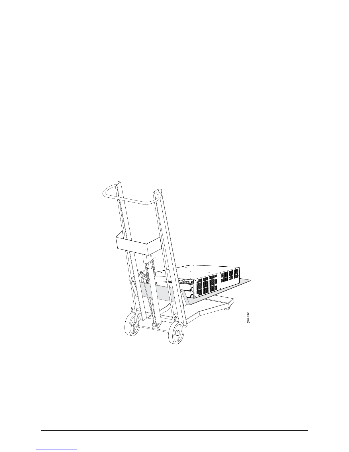
0
1
2
3
4
g030261
Chapter 5: Installing the SRX3400 Services Gateway
Related
Documentation
SRX3400 Services Gateway Definition of Safety Warning Levels on page 139•
• Preparing the SRX3400 Services Gateway for Rack-Mount or Cabinet Installation on
page 51
• Installing the SRX3400 Services Gateway in a Rack or Cabinet Using a Mechanical Lift
on page 53
Installing the SRX3400 Services Gateway in a Rack or Cabinet Using a Mechanical Lift
1. Ensure the rack is in its permanent location and is secured to the building. Ensure that
the installation site allows adequate clearance for both airflow and maintenance. For
details, see “SitePreparationChecklist for theSRX3400 Services Gateway” onpage 37.
2. Load the servicesgateway ontothe lift, making sure it restssecurely on the lift platform
(see Figure 26 on page 53).
Figure 26: Load the Services Gateway onto the Lift
3. Using the lift, position the services gateway in the rack:
•
For two-post rack mounting, align the bottom hole in each mounting bracket with
a hole in each rack rail.
•
For four-post rack or cabinet mounting, position the services gateway so that the
bottom rear edge of the chassis rests on the support shelf you installed earlier, as
described in “Installingthe MountingHardwarefor the SRX3400Services Gateway”
on page 51.
53Copyright © 2013, Juniper Networks, Inc.
Page 68
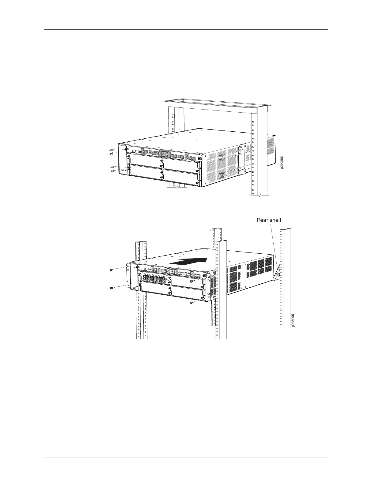
0
1
2
3
4
g030258
0
1
2
3
4
g036095
Rear shelf
SRX3400 Services Gateway Hardware Guide
4. Install a mounting screw into each of the two aligned holes, as shown in
Figure 27 on page 54 (two-post rack) or Figure 28 on page 54 (four-post rack). Use a
number-2 Phillips screwdriver to tighten the screws.
Figure 27: Installing the Services Gateway in a Two-Post Rack
Figure 28: Installing the Services Gateway in a Four-Post Rack
5. Install the remaining screws in each mounting bracket.
6. Move the lift away from the rack.
7. Visually inspect the alignment of the services gateway. If the services gateway is
installed properly in the rack, all the mounting screws on one side of the rack should
be aligned with the mounting screws on the opposite side and the services gateway
should be level.
Related
Documentation
SRX3400 Services Gateway Definition of Safety Warning Levels on page 139•
• Preparing the SRX3400 Services Gateway for Rack-Mount or Cabinet Installation on
page 51
Copyright © 2013, Juniper Networks, Inc.54
Page 69

Chapter 5: Installing the SRX3400 Services Gateway
Installing the SRX3400 Services Gateway in a Rack or Cabinet Without a Mechanical
Lift
If you cannotuse amechanical lift to install the services gateway(the preferred method),
you can install it manually. Before installing the services gateway manually, you must
first remove components from the chassis, and you must reinstall the components once
the services gateway is installed in the rack. At least two people are needed to safely lift
the chassis into the rack or cabinet. With components removed, the chassis weighs
approximately 32.3 lb (14.7 kg).
Before installing the services gateway in the rack, read the safety information in “Chassis
Lifting Guidelines”on page 148. Remove the servicesgateway fromthe shippingcontainer,
as described in “Unpacking the SRX3400 Services Gateway” on page 45. Install the
mounting hardware, as described in “Installing the Mounting Hardware for the SRX3400
Services Gateway” on page 51.
•
Required Tools for Installing the SRX3400 Services Gateway Without a Mechanical
Lift on page 55
•
Removing Components from the Chassis for Manual Lifting of the SRX3400 Services
Gateway on page 55
•
Lifting the SRX3400 Services Gateway Chassis into the Rack on page 57
•
Reinstalling Components in the SRX3400 Services Gateway Chassis on page 58
Required Tools for Installing the SRX3400 Services Gateway Without a Mechanical Lift
To install the services gateway, you need the following tools and parts:
•
Phillips (+) screwdrivers, numbers 1 and 2
•
ESD grounding wrist strap
Related
Documentation
Removing Components from the Chassis for Manual Lifting of the SRX3400 Services
•
Gateway on page 55
• Lifting the SRX3400 Services Gateway Chassis into the Rack on page 57
• Reinstalling Components in the SRX3400 Services Gateway Chassis on page 58
Removing Components from the Chassis for Manual Lifting of the SRX3400 Services Gateway
To make the services gateway light enough to install manually, you first remove the
following components from the chassis, as shown in Figure 29 on page 56 and
Figure 30 on page 56:
•
Power supplies
•
SFB
•
IOCs
•
NP-IOCs
55Copyright © 2013, Juniper Networks, Inc.
Page 70
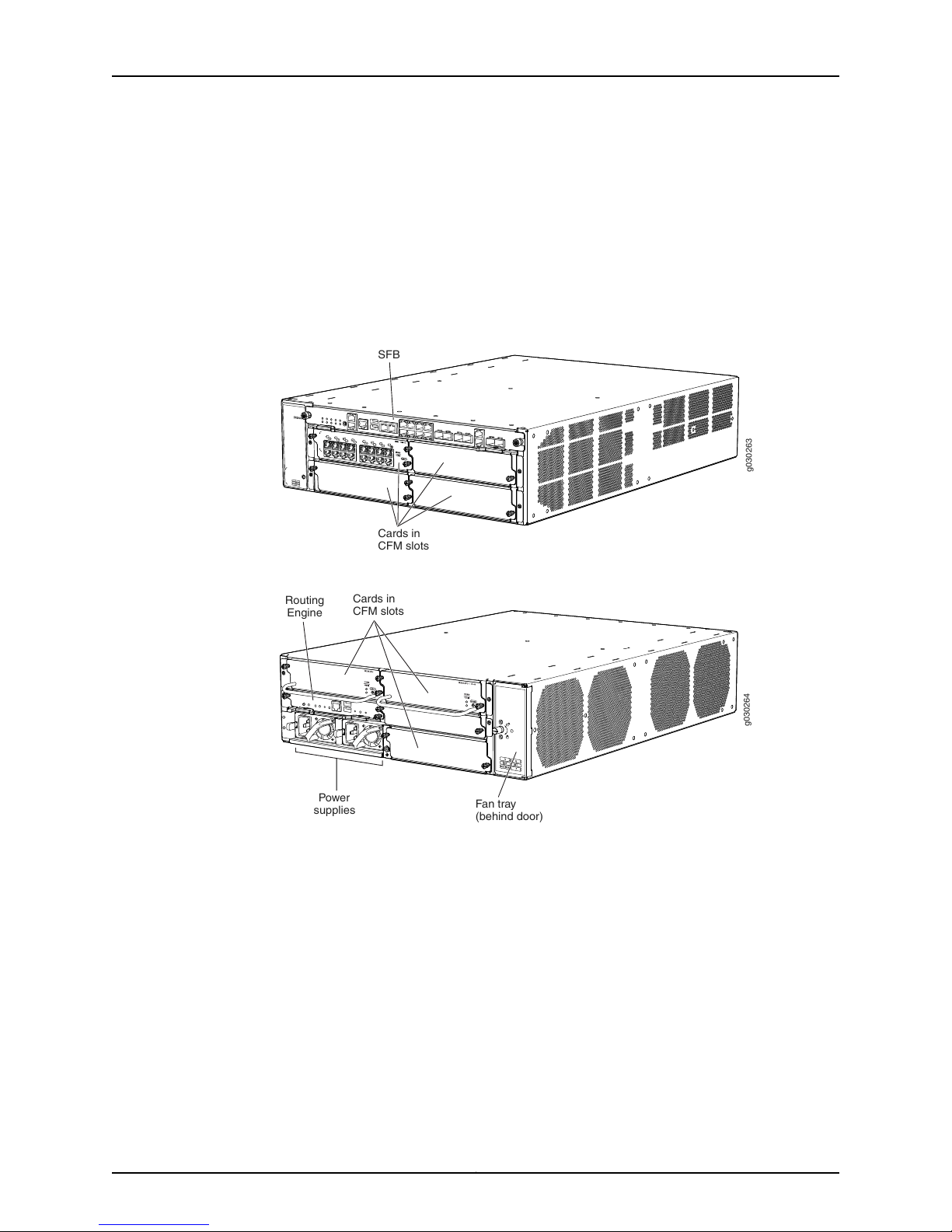
0
1
2
3
4
g030263
Cards in
CFM slots
SFB
g030264
Power
supplies
Routing
Engine
Fan tray
(behind door)
Cards in
CFM slots
SRX3400 Services Gateway Hardware Guide
•
NPCs
•
SPCs
•
Fan tray
The procedure in this section for removing components from the chassis is for initial
installation only, and assumes that you have not connected power cables to the services
gateway.
Figure 29: Components to Remove from the Front of the Services Gateway
Figure30: Components to Removefrom the Rear of the Services Gateway
To remove the components from the services gateway:
1. Attach an ESD grounding strap to your bare wrist and connect the strap to one of the
ESD points on the chassis. For more information about ESD, see “Preventing
Electrostatic Discharge Damage to the SRX3400 Services Gateway” on page 145.
2. If you have not already done so, power off the services gateway by pressing the Power
button on the front panel of the SFB for three to five seconds. The PWR LED blinks to
show you that the services gateway is shutting down. Wait for the services gateway
to shut down before you proceed to the next step.
3. Release each component by loosening its retaining screws and unlatching its ejector
handles as appropriate.
Copyright © 2013, Juniper Networks, Inc.56
Page 71

Chapter 5: Installing the SRX3400 Services Gateway
4. Slide each component out of the chassis evenly so that it does not become stuck or
damaged.
5. Label each component as you remove it so you can reinstall it in the correct location.
6. Immediately store each removed component in an electrostatic bag.
7. Do not stack removed components. Lay each one on a flat surface.
Related
Documentation
Required Tools for Installing the SRX3400 Services Gateway Without a Mechanical
•
Lift on page 55
• Lifting the SRX3400 Services Gateway Chassis into the Rack on page 57
• Reinstalling Components in the SRX3400 Services Gateway Chassis on page 58
Lifting the SRX3400 Services Gateway Chassis into the Rack
Lifting the chassis and mounting it in a rack requires two people. The empty chassis
weighs approximately 32.3 lb (14.7 kg).
1. Ensure the rack is in its permanent location and is secured to the building.
2. Position the chassis in front of the rack or cabinet. Use a pallet jack if one is available.
3. With one person on each side, lift the chassis into position in the rack:
•
For two-post rack mounting, align the bottom hole in each mounting bracket with
a hole in each rack rail.
•
For four-post rack or cabinet mounting, position the services gateway so that the
bottom rear edge of the chassis rests on the support shelf you installed earlier, as
described in “Installingthe MountingHardwarefor the SRX3400Services Gateway”
on page 51.
WARNING: Do not attemptto lift the chassis by the handles on the power
supplies or on the common form-factor modules (CFMs). The handles
might break off and cause the chassis to fall and inflict injury.
57Copyright © 2013, Juniper Networks, Inc.
Page 72
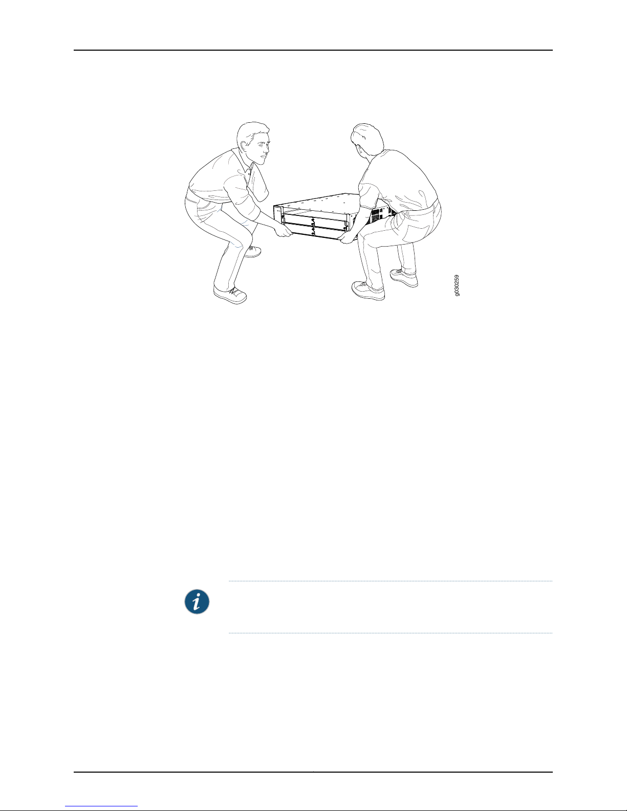
0
1
2
3
4
g030259
SRX3400 Services Gateway Hardware Guide
Figure 31: Lifting the Chassis into the Rack
4. Use the screws to attach the left and right brackets to the rack.
5. Visually inspect the alignment of the chassis. If the chassis is installed properly in the
rack, all the mounting screws on one side of the rack should be aligned with the
mounting screws on the opposite side and the chassis should be level.
Related
Documentation
Installing the Mounting Hardware for the SRX3400 Services Gateway on page 51•
• Required Tools for Installing the SRX3400 Services Gateway Without a Mechanical
Lift on page 55
• Removing Components from the Chassis for Manual Lifting of the SRX3400 Services
Gateway on page 55
• Reinstalling Components in the SRX3400 Services Gateway Chassis on page 58
Reinstalling Components in the SRX3400 Services Gateway Chassis
1. Slide each component into the chassis evenly so that it does not become stuck or
damaged.
2. Tighten the latching levers and captive screws for each component as appropriate.
NOTE: Make sure that all empty slots are covered with blank panels before
operating the services gateway.
Related
Documentation
• Required Tools for Installing the SRX3400 Services Gateway Without a Mechanical
Lift on page 55
• Removing Components from the Chassis for Manual Lifting of the SRX3400 Services
Gateway on page 55
• Lifting the SRX3400 Services Gateway Chassis into the Rack on page 57
Copyright © 2013, Juniper Networks, Inc.58
Page 73

CHAPTER 6
Installing Additional Components in the
SRX3400 Services Gateway
This section provides instructions for installing the supported cards and subsystem
components that are not pre-installed at the factory. Note that the services gateway
requires one NPC or NP-IOC and one SPC forproper operation. Additional IOCs,NP-IOCs,
NPCs, SPCs, and power suppliesare optional.For detailed information aboutthe modules
supported by the services gateway, see the SRX1400, SRX3400, and SRX3600 Services
Gateway Module Guide at www.juniper.net/techpubs/.
This section includes the following topics:
•
Installing CFM Cards in the SRX3400 Services Gateway on page 59
•
Installing SPCs inan Operating SRX3400 ServicesGateway Chassis Cluster onpage 62
•
Installing an SCM in the SRX3400 Services Gateway on page 65
•
Installing an AC Power Supply in the SRX3400 Services Gateway on page 66
•
Installing a DC Power Supply in the SRX3400 Services Gateway on page 69
Installing CFM Cards in the SRX3400 Services Gateway
The most common modules for the services gateway use the common form-factor
module (CFM) format:
•
IOCs
•
NP-IOCs
•
SPCs
•
NPCs
59Copyright © 2013, Juniper Networks, Inc.
Page 74

SRX3400 Services Gateway Hardware Guide
To install a CFM card in the services gateway:
1. Locate an eligible slot for the CFM in the services gateway. For information about the
slot eligibility of various CFM types, see “Hardware Component Locations in the
SRX3400 Services Gateway Chassis” on page 11. For information about the slot
eligibility of specific CFMs, see the SRX1400, SRX3400, and SRX3600 Services Gateway
Module Guide at www.juniper.net/techpubs/.
NOTE: If your services gateway is part of an operating chassis cluster, you
might be able to install additional SPCs in the clustered devices without
shutting down both of the devices at the same time. This process, called
in-service hardware upgrade (ISHU), eliminates the network downtime you
wouldotherwise incur while adding SPCs. For more information,see “Installing
Services Processing Cards in an Operating SRX3400 Services Gateway
Chassis Cluster” on page 62.
NOTE: For the services gateway to meet NEBS and ETSI standards, it
must not have any two SPCs installed side by side in the CFM slots in the
front of the chassis (CFM slots 1 through 4). You can install SPCs side by
side in the CFM slots in the rear of the chassis (CFM slots 5 through 7).
See“SRX3400 ServicesGatewayNEBSand ETSICompliance” on page176
for more information.
2. Attach an ESD grounding strap to your bare wrist and connect the strap to one of the
ESD points on the chassis. For more information about ESD, see “Preventing
Electrostatic Discharge Damage to the SRX3400 Services Gateway” on page 145.
3. If you are installing a cold-swap-only CFM, power off the services gateway. See
Field-Replaceable Units on the SRX3600 Services Gateway for a list of hot-swappable
and cold-swap-only components.
To power off the services gateway, press the Power button on the front panel of the
Switch Fabric Board (SFB) for three to five seconds.
The PWR LED blinks to show you that the services gateway is shutting down. Wait for
the services gateway to shut down before you proceed to the next step.
4. Place the CFM on an antistatic mat or remove it from its electrostatic bag.
5. If the slot is covered by a blank panel, loosen the screws at each end of the blank
panel and remove the blank panel from the services gateway.
NOTE: If a slot is not occupied by a card, you must install a blank panel
to shield the empty slot and to allow cooling air to circulate properly
through the services gateway.
6. Orient the CFM so that the faceplate faces you. Slide the CFM all the way into the
card cage until you feel resistance (Figure 32 on page 61).
Copyright © 2013, Juniper Networks, Inc.60
Page 75
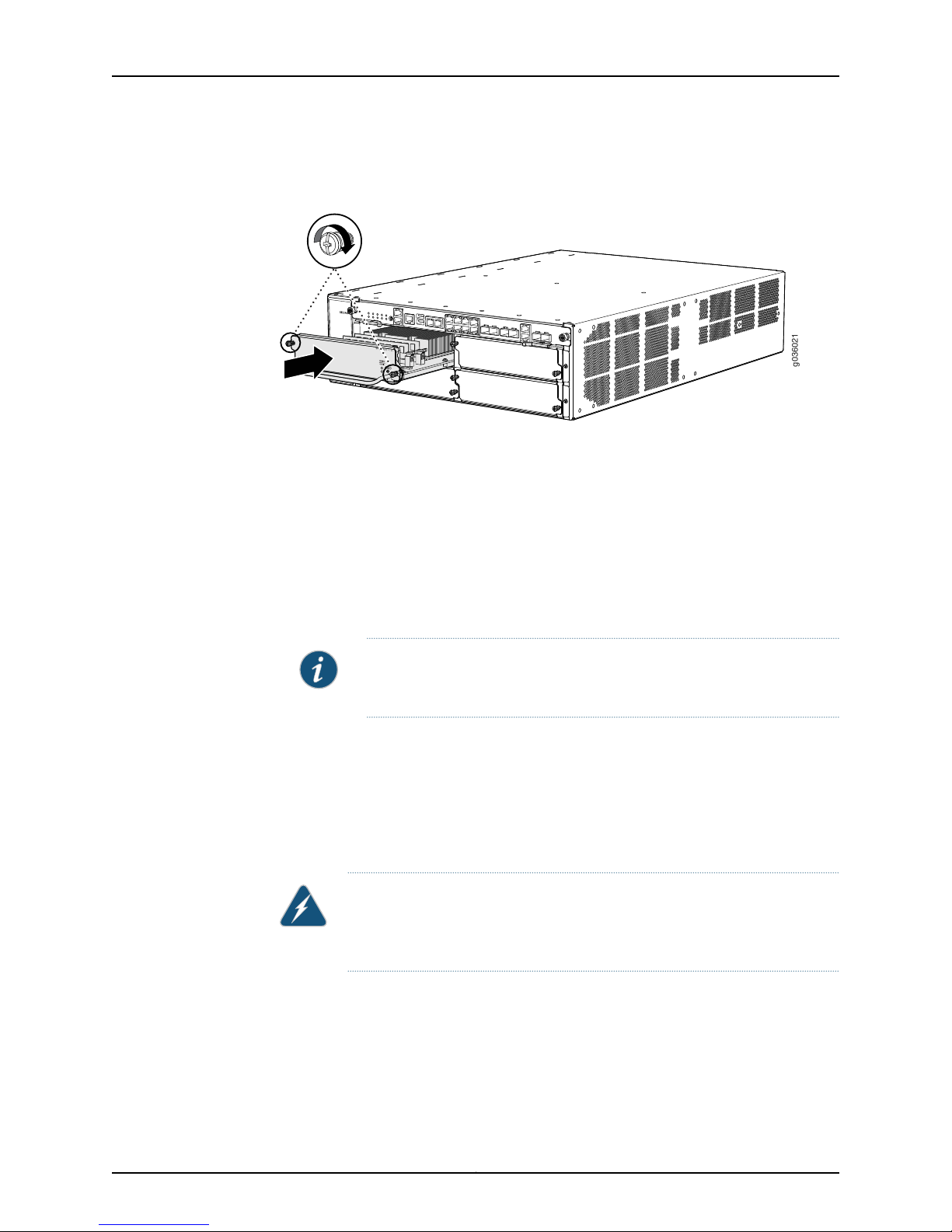
0
1
2
3
4
g036021
S
R
X3 K-SPC -1-10 -4 0
Chapter 6: Installing Additional Components in the SRX3400 Services Gateway
7. Tighten the screws on either side of the card (Figure 32 on page 61).
Figure 32: Installing a CFM (SPC Shown, Other CFMs Similar)
8. If you are installing additional CFMs at this time, repeat steps 4 through 7, and then
continue with the following steps to connect the appropriate cables.
9. Insert theappropriatecables into thecable connector portson each CFM as applicable.
Securethe cables sothat they arenot supportingtheir ownweight. Place excess cable
out of the way in a neatly coiled loop. Placing fasteners on a loop helps to maintain
its shape.
Related
Documentation
10. If you insertedhot-swappableCFMs suchas NP-IOCs without powering offthe services
gateway, bring each new CFM online and power it on by pressing its ONLINE button
for five or more seconds.
NOTE: You may find it easiest to use a pen, screwdriver, or other tool to
press the button.
11. If you powered off the services gatewayto installCFMs, power onthe servicesgateway,
as described in Powering On the SRX3600 Services Gateway.
12. Check the OK/FAIL LED on each new CFM. The OK/FAIL LED on the CFM faceplate
should blink green, then light steadily. If it is red, remove and reinstall the CFM. If the
OK/FAIL LED remains red, the CFM is not functioning properly. Contact your customer
support representative.
WARNING: Never lift the services gateway using the handles on the front
panels of the CFM cards. The handles might come off, causing the chassis
to drop and inflicting possible grave injury.
Preventing Electrostatic Discharge Damage to the SRX3400 Services Gateway on
•
page 145
• SRX3400 Services Gateway NEBS and ETSI Compliance on page 176
• Installing Services Processing Cards in an Operating SRX3400 Services Gateway
Chassis Cluster on page 62
61Copyright © 2013, Juniper Networks, Inc.
Page 76

SRX3400 Services Gateway Hardware Guide
• Hardware Component Locations in the SRX3400 Services Gateway Chassis on page 11
Installing SPCs in an Operating SRX3400 Services Gateway Chassis Cluster
If your SRX3600 Services Gateway is part of a chassis cluster, you can install additional
SPCs inthe servicesgateways inthe clusterwithout incurring downtime on your network.
This process is sometimes called in-service hardware upgrade (ISHU).
To perform such an installation, it must meet the following conditions:
•
If the chassis cluster is operating in active-active mode, you must transition it to
active-passive mode before using this procedure. You transition the cluster to
active-passive mode by making one node primary for all redundancy groups.
•
Both of the services gateways inthe cluster mustbe running JunosOS Release11.4R2S1,
12.1R2, or later.
•
You must install SPCs of the same type in both of the services gateways in the cluster.
•
You must install the SPCs in the same slots in each chassis.
•
You must install the SPCs so that they are not the SPCs with the lowest-numbered
slots in the chassis. For example, if the chassis already has two SPCs with one SPC
each in slots 2 and 3, you cannot install additional SPCs in slots 0 or 1 using this
procedure.
If yourinstallationdoes not meet thesecriteria, usethe procedure in “Installing CFM Cards
in the SRX3400 Services Gateway” on page 59 to install SPCs in your services gateway.
NOTE: During this installation procedure, you must shut down both devices,
one at a time. During the period when one device is shut down, the remaining
deviceoperateswithout a backup. If that remaining devicefails for any reason,
you incur network downtime until you restart at least one of the devices.
NOTE: If the services gateway only has one SPC installed, you must make
sure that the full-cp-key license that enables large central point mode is not
installed. If the license is installed when you upgrade from a single SPC to
multiple SPCs, it changes the mode of the SPC in the lowest numbered slot
from combo mode to large central point. After that change, the run time
objects (RTOs) do not synchronize properly between the two devices in the
cluster, and you incur network downtime while the devices discard their
existing RTOs and rebuild their RTO tables.
Copyright © 2013, Juniper Networks, Inc.62
Page 77

Chapter 6: Installing Additional Components in the SRX3400 Services Gateway
To install SPCs in an SRX3400 Services Gateway cluster without incurring downtime:
1. Use the console port on the Routing Engine to establish a command-line interface
(CLI) session with one of the devices in the cluster.
2. Use the show chassis cluster status command to determine which services gateway
is currently primary, and which services gateway is secondary, within the cluster.
In the example below, all redundancy groups are primary on node 0, and secondary
on node 1:
admin@cluster> show chassis cluster status
Cluster ID: 1
Node Priority Status Preempt Manual failover
Redundancy group: 0 , Failover count: 5
node0 1 primary no no
node1 100 secondary no no
Redundancy group: 1 , Failover count: 1
node0 200 primary no no
node1 100 secondary no no
Redundancy group: 2 , Failover count: 1
node0 200 primary no no
node1 100 secondary no no
Redundancy group: 3 , Failover count: 1
node0 100 primary no no
node1 200 secondary no no
Redundancy group: 4 , Failover count: 1
node0 200 primary no no
node1 100 secondary no no
3. If the device with which you established the CLI session in Step 2 is not the secondary
node in the cluster, use the console port on the device that is the secondary node to
establish a CLI session.
4. If the services gateway has only one SPC installed in it, in the CLI session for the
secondary services gateway, use the show system license command to make sure
the device does not have the full-cp-key license installed:
admin@node1_device> show system license
License usage:
Licenses Licenses Licenses Expiry
Feature name used installed needed
full-cp-key 0 1 0 permanent
logical-system 1 1 0 permanent
Licenses installed:
License identifier: JUNOS274930
License version: 2
Valid for device: AB3210AA0016
Features:
full-cp-key - Expanded CP performance and capacity
permanent
63Copyright © 2013, Juniper Networks, Inc.
Page 78

SRX3400 Services Gateway Hardware Guide
5. If the services gateway has only one SPC installed and the full-cp-key license is also
installed, record the identifier of the full-cp-key license from the command output of
the previous step. Then use the following command to remove the license:
admin@node1_device> request system license delete identifier
6. In the CLI session for the secondary services gateway, use the request system power
off command to shut down the services gateway.
7. Wait for the secondary services gateway to completely shut down.
8. Install the new SPC or SPCs in the powered-off services gateway using the procedure
in “Installing CFM Cards in the SRX3400 Services Gateway” on page 59.
9. Power on the secondary services gateway and wait for it to finish starting.
10. Reestablish the CLI session with the secondary node device.
11. Use the show chassis fpc pic-status command to make sure that all of the cards in
the secondary node chassis are back online.
In the example below, the second column shows that all of the cards are online. This
example is for an SRX3400 Services Gateway; for other devices the output will be
similar.
admin@node1_device> show chassis fpc pic-status
node0:
-------------------------------------------------------------------------Slot 0 Online SRX3k SFB 12GE
PIC 0 Online 8x 1GE-TX 4x 1GE-SFP
Slot 1 Online SRX3k SPC
PIC 0 Online SPU Cp-Flow
Slot 2 Online SRX3k SPC
PIC 0 Online SPU Flow
Slot 3 Online SRX3k 2x10GE XFP
PIC 0 Online 2x 10GE-XFP
Slot 5 Online SRX3k SPC
PIC 0 Online SPU Flow
Slot 6 Online SRX3k NPC
PIC 0 Online NPC PIC
node1:
-------------------------------------------------------------------------Slot 0 Online SRX3k SFB 12GE
PIC 0 Online 8x 1GE-TX 4x 1GE-SFP
Slot 1 Online SRX3k SPC
PIC 0 Online SPU Cp-Flow
Slot 2 Online SRX3k SPC
PIC 0 Online SPU Flow
Slot 3 Online SRX3k 2x10GE XFP
PIC 0 Online 2x 10GE-XFP
Slot 5 Online SRX3k SPC
PIC 0 Online SPU Flow
Slot 6 Online SRX3k NPC
PIC 0 Online NPC PIC
{secondary:node1}
Copyright © 2013, Juniper Networks, Inc.64
Page 79

Chapter 6: Installing Additional Components in the SRX3400 Services Gateway
12. Use the show chassis cluster status command to make sure that the priority for all
redundancy groups is greater than zero.
13. Use the console port on the device that is the primary node to establish a CLI session.
14. In the CLIsession forthe primary node device,use the request chassis cluster failover
command to fail over each redundancy group that has an ID number greater than
zero.
For example:
admin@node0_device> request chassis cluster failover redundancy-group 1 node 1
admin@node0_device> request chassis cluster failover redundancy-group 2 node 1
admin@node01_device> request chassis cluster failover redundancy-group 3 node
1
admin@node0_device> request chassis cluster failover redundancy-group 4 node 1
15. If the services gateway has only one SPC in it and the full-cp-key license is installed,
remove the full-cp-key license as described in Step 5.
16. In the CLI session for the primary node device, use the request system power off
command to shut down the services gateway. This action causes redundancy group
0 to fail over onto the other services gateway, making it the active node in the cluster.
17. Install the new SPC or SPCs in the powered-off services gateway using the procedure
in “Installing CFM Cards in the SRX3400 Services Gateway” on page 59.
18. Power on the services gateway and wait for it to finish starting.
19. Use the show chassis fpc pic-status command on each node toconfirm that allcards
are online and both services gateways are operating correctly.
20. Use the show chassis cluster status command to make sure that the priority for all
redundancy groups is greater than zero.
Related
Installing CFM Cards in the SRX3400 Services Gateway on page 59•
Documentation
Installing an SCM in the SRX3400 Services Gateway
You install the SRX Clustering Module (SCM) in the RE1 slot on the rear panel of the
services gateway. To install the SCM:
1. Attach an ESD grounding strap to your bare wrist and connect the strap to one of the
ESD points on the chassis. For more information about ESD, see “Preventing
Electrostatic Discharge Damage to the SRX3400 Services Gateway” on page 145.
2. If you have not already done so, power off the services gateway by pressing the Power
button on the front panel of the SFB for three to five seconds.
The PWR LED blinks to show you that the services gateway is shutting down. Wait for
the services gateway to shut down before you proceed to the next step.
65Copyright © 2013, Juniper Networks, Inc.
Page 80
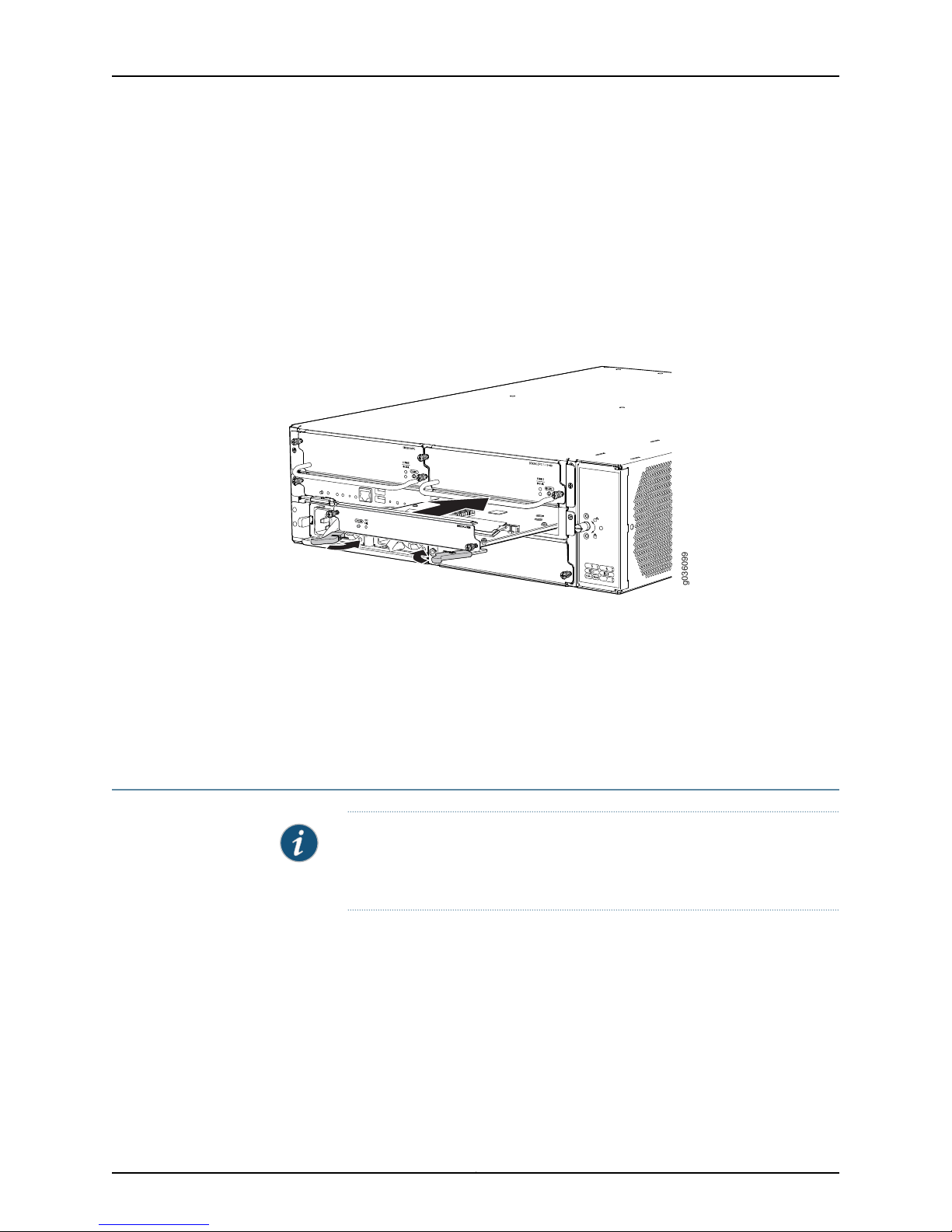
g036099
SRX3400 Services Gateway Hardware Guide
3. Loosen the captive screws at each end of the blank faceplate over the RE1 slot and
remove the faceplate.
4. Place the SCM on an antistatic mat or remove it from its electrostatic bag and place
it on the bag.
5. Press both of the ejector handles on the SCM faceplate outward to release them.
6. Orient the SCM so that its faceplate faces you. Slide the SCM all the way into the card
cage until you feel resistance. See Figure 33 on page 66.
Figure 33: Installing the SCM in the SRX3400 Services Gateway
7. Press both of the ejector handles inward to seat the SCM.
8. Tighten the screws on either side of the SCM faceplate.
Related
Documentation
SRX3400 Services Gateway SRX Clustering Module on page 24•
• Replacing an SRX Clustering Module on the SRX3400 Services Gateway on page 120
Installing an AC Power Supply in the SRX3400 Services Gateway
NOTE: For the services gateway to meet NEBS and ETSI standards, both AC
powersupplies mustbe Revision09 or later.See“SRX3400 ServicesGateway
NEBS and ETSI Compliance” on page 176 for more information.
Copyright © 2013, Juniper Networks, Inc.66
Page 81
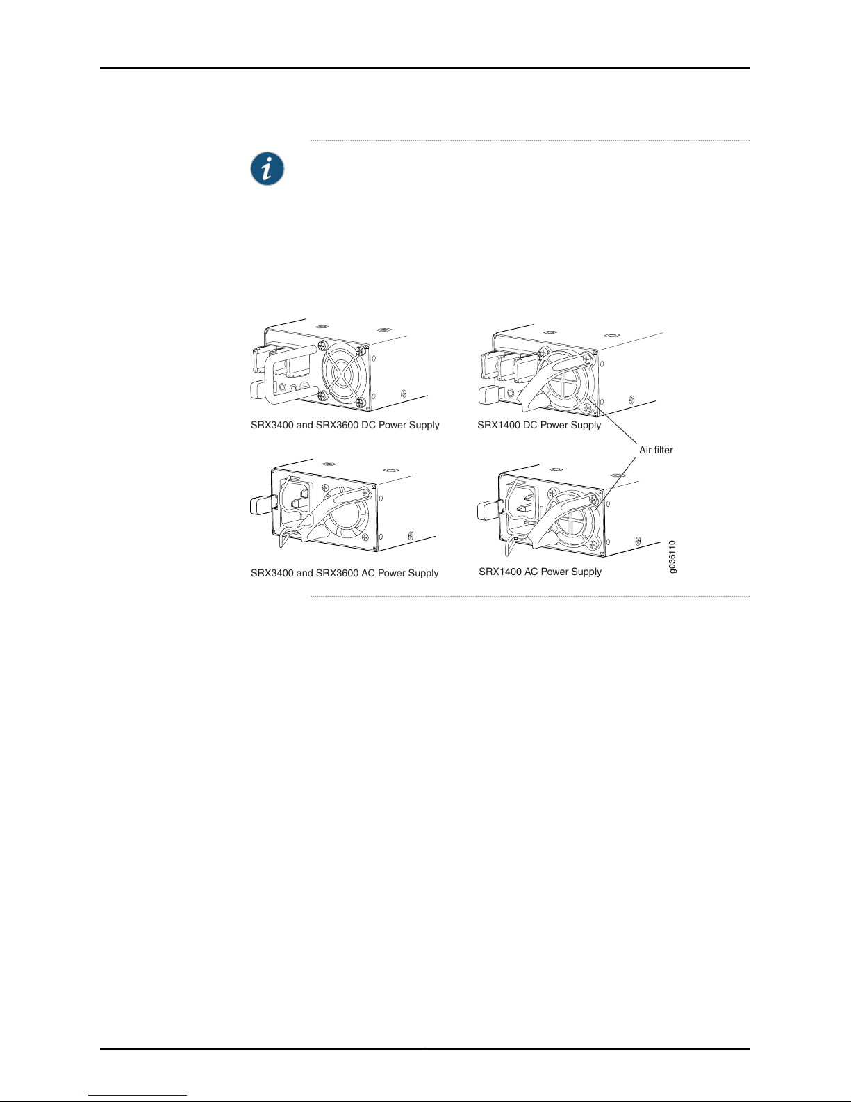
g036110
Air filter
SRX3400 and SRX3600 DC Power Supply
SRX3400 and SRX3600 AC Power Supply
SRX1400 DC Power Supply
SRX1400 AC Power Supply
Chapter 6: Installing Additional Components in the SRX3400 Services Gateway
NOTE: Thesame ACpowersupply is used in both the SRX3400 and SRX3600
Services Gateways. However, this power supply is not interchangeable with
thatused in the SRX1400 ServicesGateway. The SRX1400 Services Gateway
power supply will fit into the SRX3400 Services Gateway, but will not work
properly. You can identify the SRX1400 Services Gateway power supply by
the plastic air filter assembly installed over the cooling air inlet as shown in
Figure 34 on page 67.
Figure 34: Identifying Power Supply Types
To install an AC power supply:
1. Attach an ESD grounding strap to your bare wrist and connect the strap to one of the
ESD points on the chassis. For more information about ESD, see “Preventing
Electrostatic Discharge Damage to the SRX3400 Services Gateway” on page 145.
2. Orient the power supply so that the locking lever is on the left, as shown in
Figure 35 on page 68.
67Copyright © 2013, Juniper Networks, Inc.
Page 82
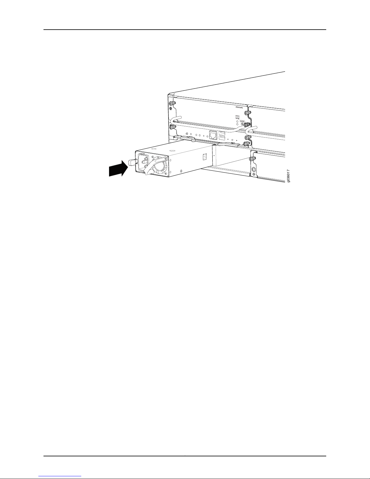
g036017
SRX3400 Services Gateway Hardware Guide
Figure 35: Installing an AC Power Supply
3. Using both hands, slide the power supply straight into the chassis until the power
supply is fully seated in the chassis slot. The power supply faceplate should be flush
with any adjacent power supply faceplate or blank installed in the power supply slot.
Related
Documentation
See “Connecting the SRX3400 Services Gateway to an AC Power Source” on page 77
for information on connecting the power supply to AC power.
Installing CFM Cards in the SRX3400 Services Gateway on page 59•
• Installing a DC Power Supply in the SRX3400 Services Gateway on page 69
Copyright © 2013, Juniper Networks, Inc.68
Page 83
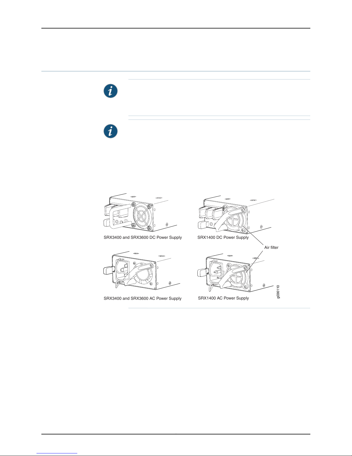
g036110
Air filter
SRX3400 and SRX3600 DC Power Supply
SRX3400 and SRX3600 AC Power Supply
SRX1400 DC Power Supply
SRX1400 AC Power Supply
Chapter 6: Installing Additional Components in the SRX3400 Services Gateway
Installing a DC Power Supply in the SRX3400 Services Gateway
NOTE: For the services gateway to meet NEBS and ETSI standards, both DC
powersupplies must be enhancedDC power supplies.See “SRX3400Services
Gateway NEBS and ETSI Compliance” on page 176 for more information.
NOTE: Thesame DC power supply is used in both the SRX3400 and SRX3600
Services Gateways. However, this power supply is not interchangeable with
thatused in the SRX1400 ServicesGateway. The SRX1400 Services Gateway
power supply will fit into the SRX3400 Services Gateway, but will not work
properly. You can identify the SRX1400 Services Gateway power supply by
the plastic air filter assembly installed over the cooling air inlet as shown in
Figure 36 on page 69.
Figure 36: Identifying Power Supply Types
To install a DC power supply:
1. Ensure that the voltage across the DC power source cable leads is 0 V and that there
is no chance that the cable leads might become active during installation.
2. Attach an ESD grounding strap to your bare wrist and connect the strap to one of the
ESD points on the chassis. For more information about ESD, see “Preventing
Electrostatic Discharge Damage to the SRX3400 Services Gateway” on page 145.
3. Orient the power supply so that the locking lever is on the left, as shown in
Figure 37 on page 70.
69Copyright © 2013, Juniper Networks, Inc.
Page 84
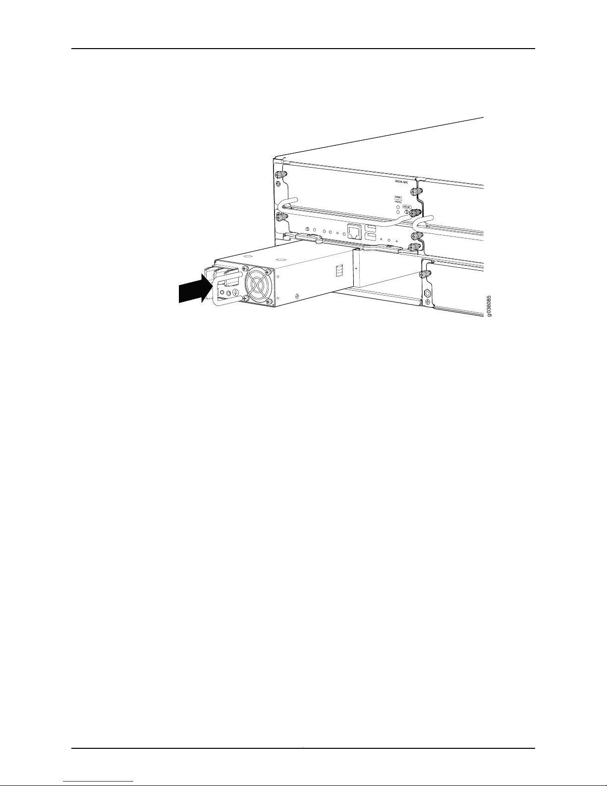
g036085
SRX3400 Services Gateway Hardware Guide
Figure 37: Installing a DC Power Supply
Related
Documentation
4. Using both hands, slide the power supply straight into the chassis until the power
supply is fully seated in the chassis slot. The power supply faceplate should be flush
with any adjacent power supply faceplate.
See “Connecting the SRX3400 Services Gateway to a DC Power Source” on page 79 for
information on connecting the power supply to DC power.
• Installing CFM Cards in the SRX3400 Services Gateway on page 59
• Installing an AC Power Supply in the SRX3400 Services Gateway on page 66
Copyright © 2013, Juniper Networks, Inc.70
Page 85

CHAPTER 7
Connecting the SRX3400 Services
Gateway
This section includes the following topics:
•
Required Tools and Parts for Connecting the SRX3400 Services Gateway on page 71
•
Connecting the SRX3400 Services Gateway to Management Devices on page 71
Required Tools and Parts for Connecting the SRX3400 Services Gateway
To connect the services gateway to management devices and to power on the services
gateway, you need the following tools and parts:
•
Phillips (+) screwdrivers, numbers 1 and 2
•
2.5-mm flat-blade (–) screwdriver
•
Wire cutters
•
Pliers
•
Electrostatic discharge (ESD) grounding wrist strap
Related
Documentation
Connecting the SRX3400Services Gatewayto a Networkfor Out-of-Band Management
•
on page 72
• Connecting the SRX3400 Services Gateway to a Management Console or an Auxiliary
Device on page 72
• Grounding the SRX3400 Services Gateway on page 76
Connecting the SRX3400 Services Gateway to Management Devices
After you have installed the services gateway into the rack, attach one or more external
devices to the ports on the SFB that connect to the installed Routing Engine for
management and service operations.
71Copyright © 2013, Juniper Networks, Inc.
Page 86

SRX3400 Services Gateway Hardware Guide
To connect external devices to the SFB management ports, perform the procedures
described in the following topics:
•
Connecting the SRX3400 Services Gateway to a Network for Out-of-Band
Management on page 72
•
Connecting the SRX3400 Services Gateway to a Management Console or an Auxiliary
Device on page 72
Connecting the SRX3400 Services Gateway to a Network for Out-of-Band Management
To connect the Routing Engine to a network for out-of-band management:
1. Plug one end of an Ethernet cable with RJ-45 connectors (Figure 38 on page 72 shows
the connector) into the RE ETHERNET 0 port on the front of the SFB.
Figure 38: SFB Ethernet Cable Connector
One Ethernet cable is provided with the services gateway.
2. Plug the other end of the cable into the network device.
Related
Documentation
Required Tools and Parts for Connecting the SRX3400 Services Gateway on page 71•
• Connecting the SRX3400 Services Gateway to a Management Console or an Auxiliary
Device on page 72
• Grounding the SRX3400 Services Gateway on page 76
• Console Port Cable and Wire Specifications for the SRX3400 Services Gateway on
page 200
• SRX3400 Services Gateway Switch Fabric Board on page 14
Connecting the SRX3400 Services Gateway to a Management Console or an Auxiliary Device
To use a system console to configure and manage the Routing Engine, connect it to one
of the RE CONSOLE ports on the SFB using the RJ-45 cable.
To connect a management console or an auxiliary device:
1. Plug the RJ-45 end of the cable (Figure 40 on page 73 shows the connector) into the
RE CONSOLE 0 port on the SFB.
2. Plug the female DB-9 end into the device's serial port.
Copyright © 2013, Juniper Networks, Inc.72
Page 87

g036011
Chapter 7: Connecting the SRX3400 Services Gateway
Figure 39: Connecting to the Console Port
Figure 40: Console and Auxiliary Cable Connector
Related
Documentation
NOTE:
For console devices, configure the serial port to the following values:
•
Baud rate—9600
•
Parity—N
•
Data bits—8
•
Stop bits—1
•
Flow control—none
• Required Tools and Parts for Connecting the SRX3400 Services Gateway on page 71
• Connecting the SRX3400 Services Gateway to aNetworkfor Out-of-BandManagement
on page 72
• Grounding the SRX3400 Services Gateway on page 76
• Console Port Cable and Wire Specifications for the SRX3400 Services Gateway on
page 200
• SRX3400 Services Gateway Switch Fabric Board on page 14
73Copyright © 2013, Juniper Networks, Inc.
Page 88

SRX3400 Services Gateway Hardware Guide
Copyright © 2013, Juniper Networks, Inc.74
Page 89

CHAPTER 8
Grounding and Providing Power to the
SRX3400 Services Gateway
This section includes the following topics:
•
Required Tools and Parts for Grounding and Providing Power to the SRX3400 Services
Gateway on page 75
•
Grounding the SRX3400 Services Gateway on page 76
•
Connecting the SRX3400 Services Gateway to an AC Power Source on page 77
•
Connecting the SRX3400 Services Gateway to a DC Power Source on page 79
•
Powering On the SRX3400 Services Gateway on page 81
•
Powering Off the SRX3400 Services Gateway on page 82
RequiredTools and Parts for Grounding and Providing Power to the SRX3400 Services
Gateway
Related
Documentation
To ground and provide power to the services gateway, you need the following tools and
parts:
•
Phillips (+) screwdrivers, numbers 1 and 2
•
2.5-mm flat-blade (–) screwdriver
•
Wire cutters
•
Electrostatic discharge (ESD) grounding wrist strap
Grounding the SRX3400 Services Gateway on page 76•
• Connecting the SRX3400 Services Gateway to an AC Power Source on page 77
• Connecting the SRX3400 Services Gateway to a DC Power Source on page 79
• Powering On the SRX3400 Services Gateway on page 81
• Powering Off the SRX3400 Services Gateway on page 82
75Copyright © 2013, Juniper Networks, Inc.
Page 90
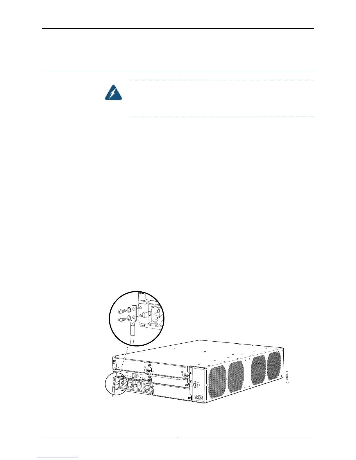
g036091
SRX3400 Services Gateway Hardware Guide
Grounding the SRX3400 Services Gateway
WARNING: To meet safety and electromagnetic interference (EMI)
requirements and to ensure proper operation, you must properly ground the
services gateway chassis before connecting power.
You ground the services gateway by connecting a grounding cable to earth ground and
then attaching it to the chassis grounding point using two M5 screws. You must provide
the grounding cable (the cable lug is supplied with the services gateway). For grounding
cable specifications, see “SRX3400 Services Gateway Grounding Cable Specification”
on page 183.
1. Verify that a licensed electricianhas attached the cable lug provided with the services
gateway to the grounding cable.
2. Attachan ESDgrounding strap toyour bare wrist and connectthe strap toan approved
site ESD grounding point. See the instructions for your site.
3. Ensure that all grounding surfaces are clean and brought to a bright finish before
grounding connections are made.
4. Connect the grounding cable to a proper earth ground.
5. Detach the ESD grounding strap from the site ESD grounding point.
6. Attach an ESD grounding strap to your bare wrist and connect the strap to one of the
ESD points on the chassis. For more information about ESD, see “Preventing
Electrostatic Discharge Damage to the SRX3400 Services Gateway” on page 145.
7. Place the grounding cable lug over the grounding point—a pair of M5 holes to the left
of the power supply slots. See Figure 41 on page 76.
Figure 41: Connecting the Grounding Cable
Copyright © 2013, Juniper Networks, Inc.76
Page 91
Chapter 8: Grounding and Providing Power to the SRX3400 Services Gateway
8. Secure the grounding cable lug to the chassis, first with the washers, then with the
screws.
9. Dress the grounding cable and verify that it does not touch or block access to services
gateway components, and that it does not drape where people could trip on it.
Related
Documentation
Required Tools and Parts for Grounding and Providing Power to the SRX3400 Services
•
Gateway on page 75
• Connecting the SRX3400 Services Gateway to an AC Power Source on page 77
• Connecting the SRX3400 Services Gateway to a DC Power Source on page 79
• Powering On the SRX3400 Services Gateway on page 81
• Powering Off the SRX3400 Services Gateway on page 82
Connecting the SRX3400 Services Gateway to an AC Power Source
You connect AC power to the services gateway by attaching power cords from the AC
power sources to the AC appliance inlets located on the power supplies.
WARNING: To meet safety and electromagnetic interference (EMI)
requirements and to ensure proper operation, you must properly ground the
services gateway chassis before connecting power. See “Grounding the
SRX3400 Services Gateway” on page 76 for instructions.
CAUTION: Do not mix AC and DC power supplies within the same services
gateway. Damage to the services gateway might occur.
To connect the AC power cords to the services gateway for each power supply:
1. Locate the power cord or cords you will use to connect the services gateway to AC
power. The services gateway is not shipped with AC power cords. You must order
them separately using the model numbers shown in “SRX3400 Services Gateway AC
Power Cord Specifications” on page 191.
2. Insert the appliance coupler end of the power cord into the appliance inlet on the
power supply, as shown in Figure 42 on page 78.
77Copyright © 2013, Juniper Networks, Inc.
Page 92
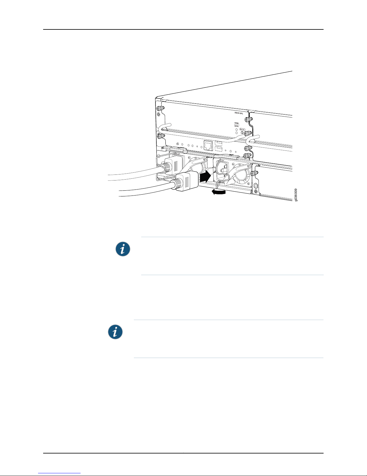
g036009
SRX3400 Services Gateway Hardware Guide
Figure 42: Connecting to AC Power
Related
Documentation
3. Snap the wire bailon the power supply over the power cord to prevent the power cord
from accidentally disengaging.
4. Insert the power cord plug into an external AC power source receptacle.
NOTE: Each power supply must be connected to a dedicated AC power
feed and a dedicated external circuit breaker. We recommend that you
use a 15 A (250 VAC) minimum, or as permitted by local code.
5. Dress the power cord appropriately. Verify that the power cord does not block the air
exhaust and access to services gateway components or drape where people could
trip on it.
6. Repeat steps 1 through 5 for the remaining power supplies.
NOTE: If power is lost to the services gateway, the Power-On/Power-Off
state is retained. For example, if the services gateway loses power while the
services gateway is on, when power returns, it will still be in the On state.
Required Tools and Parts for Grounding and Providing Power to the SRX3400 Services
•
Gateway on page 75
• SRX3400 Services Gateway AC Power Cord Specifications on page 191
• Grounding the SRX3400 Services Gateway on page 76
• Connecting the SRX3400 Services Gateway to a DC Power Source on page 79
• Powering On the SRX3400 Services Gateway on page 81
Copyright © 2013, Juniper Networks, Inc.78
Page 93
Chapter 8: Grounding and Providing Power to the SRX3400 Services Gateway
• Powering Off the SRX3400 Services Gateway on page 82
Connecting the SRX3400 Services Gateway to a DC Power Source
You connect DC power to the services gateway by attaching power cables from the
external DC power sources to the terminal studs on the power supply faceplates. You
must provide the power cables.
WARNING: Before performing the following procedure, ensure that power is
removedfrom the DC circuit. Toensure that all power is off, locate the circuit
breaker on the panel board that services the DC circuit, switch the circuit
breaker to the off position, and tape the switch handle of the circuit breaker
in the off position.
WARNING: To meet safety and electromagnetic interference (EMI)
requirements and to ensure proper operation, you must properly ground the
services gateway chassis before connecting power. See “Grounding the
SRX3400 Services Gateway” on page 76 for instructions.
CAUTION: Before services gatewayinstallationbegins, a licensed electrician
must attach appropriate cable lugs to the grounding and power cables that
you supply. A cable with an incorrectly attachedlug can damage the services
gateway.
CAUTION: Do not mix AC and DC power supplies within the same services
gateway. Damage to the services gateway might occur.
To connect the DC source power cables to the services gateway for each power supply:
1. Switch off the dedicated facility circuit breakers. Ensure that the voltage across the
DC power source cable leads is 0 V and that there is no chance that the cable leads
might become active during installation.
2. Remove the clear plastic cover protecting the terminal studs on the faceplate.
3. Verify that the DC power cables are correctly labeled before making connections to
the power supply. In a typical power distribution scheme where the returnis connected
to chassis ground at the battery plant, you can use amultimeter to verify that the ohm
output of the -48V and RTN DC cables to chassis ground. The cable with very large
resistance (indicating an open circuit) to chassis ground will be -48V and the cable
with very low resistance (indicating a closed circuit) to chassis ground will be RTN.
79Copyright © 2013, Juniper Networks, Inc.
Page 94

SRX3400 Services Gateway Hardware Guide
4. Remove the screws and square washers from the terminals. Use a number-2 Phillips
screwdriver.
5. Secure each power cable lug to the terminals, first with the square washer, then with
the screw. Apply between 23 lb-in. (2.6 Nm) and 25 lb-in. (2.8 Nm) of torque to each
screw.
•
Secure each positive (+) DC source power cable lug to a RTN (return) terminal.
•
Secure each negative (–) DC source power cable lug to a -48V (input) terminal.
6. Replace the clear plastic cover over the terminal studs on the faceplate.
CAUTION: You must ensure that power connections maintain the proper
polarity. The powersource cables might be labeled (+) and (–) to indicate
their polarity. There is no standard color coding for DC power cables. The
colorcoding used by the external DC power source at your site determines
the color coding for the leads on the power cables that attach to the
terminal studs on each power supply.
7. Verify that the power cables are connected correctly, that they are not touching or
blocking access to services gateway components, and that they do not drape where
people could trip on them.
8. If you are installing multiple power supplies, repeat steps 1 through 7 for the other
power supplies.
Copyright © 2013, Juniper Networks, Inc.80
Page 95
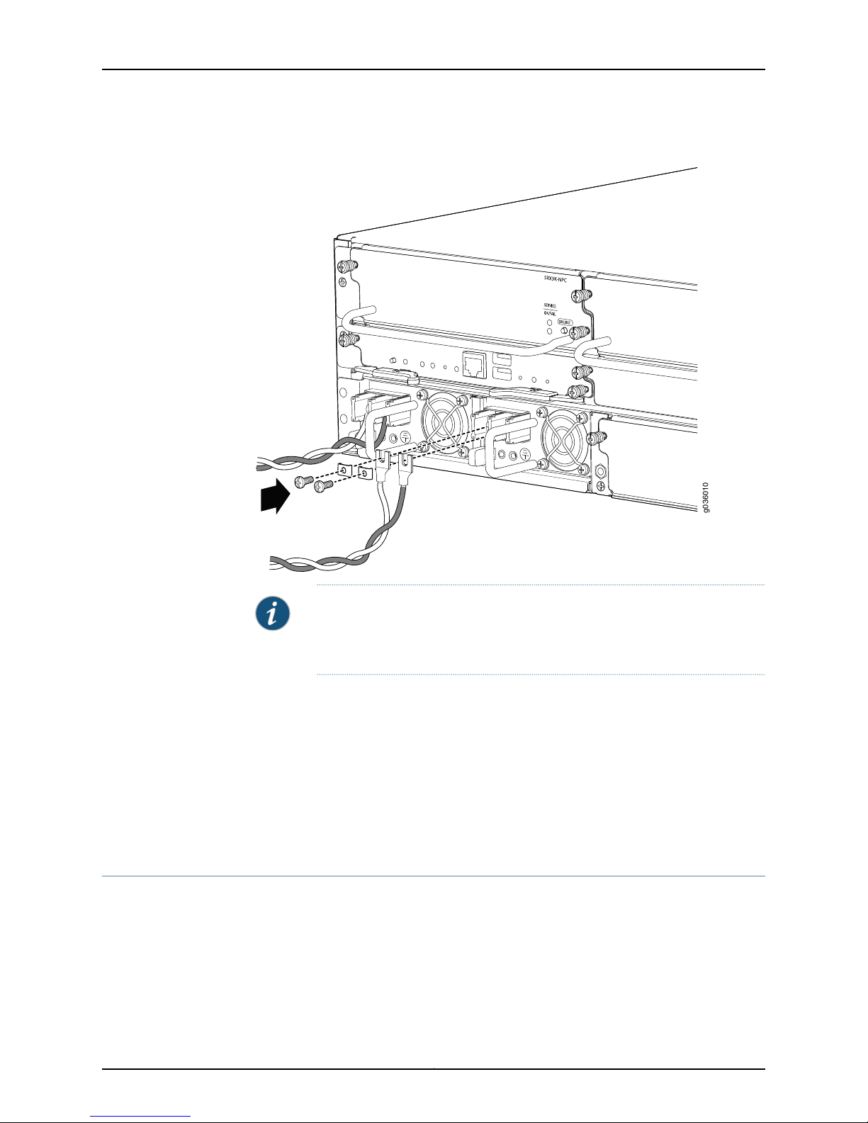
g036010
Chapter 8: Grounding and Providing Power to the SRX3400 Services Gateway
Figure 43: Connecting to DC Power
NOTE: If power is lost to the services gateway, the Power-On/Power-Off
state is retained. For example, if the services gateway loses power while the
services gateway is on, when power returns, it will still be in the On state.
Related
Documentation
Required Tools and Parts for Grounding and Providing Power to the SRX3400 Services
•
Gateway on page 75
• Grounding the SRX3400 Services Gateway on page 76
• Connecting the SRX3400 Services Gateway to an AC Power Source on page 77
• Powering On the SRX3400 Services Gateway on page 81
• Powering Off the SRX3400 Services Gateway on page 82
Powering On the SRX3400 Services Gateway
To power on the services gateway, press the Power button on the front of the SFB for
three to five seconds.
81Copyright © 2013, Juniper Networks, Inc.
Page 96
SRX3400 Services Gateway Hardware Guide
NOTE: If power is lost to the services gateway, the Power-On/Power-Off
state is retained. For example, if the services gateway loses power while it is
switched on, when power returns, the services gateway will still be in the On
state.
Related
Documentation
Required Tools and Parts for Grounding and Providing Power to the SRX3400 Services
•
Gateway on page 75
• Grounding the SRX3400 Services Gateway on page 76
• Connecting the SRX3400 Services Gateway to an AC Power Source on page 77
• Connecting the SRX3400 Services Gateway to a DC Power Source on page 79
• Powering Off the SRX3400 Services Gateway on page 82
Powering Off the SRX3400 Services Gateway
You can power off the services gateway in one of the following ways:
•
Graceful shutdown—Press and immediately release the POWER button on the front
of the SFB (for 3 to 5 seconds) to initiate graceful shutdown. The device begins
gracefully shutting down the operating system and then powers itself off.
•
Forced shutdown—Press the POWER button and hold it for 15 seconds to power down
the device immediately.
You need to press the POWER button again to power on the device.
CAUTION: Use the graceful shutdown method to power off or reboot the
services gateway whenever possible. Use the forced shutdown method as
a last resort to recover the services gateway if the services gateway
operating system is not responding to the graceful shutdown method.
•
To remove power completely from the device, unplug the AC power cord (for
AC-powered devices) or switch off the DC power source (for DC-powered devices).
After powering off the device, wait for at least 10 seconds before powering on the
device again. After powering onthe device, waitfor at least 10 seconds before powering
it off.
By default, even if you press the POWER button and hold it for 15 seconds,
the device will still do a graceful shutdown as long as the device is
responsive and operating normally. The device will resort to forced
shutdown only if it fails or does not respond to the operating system.
CAUTION: Forced shutdown can resultin data loss and corruption of the file
system.
Copyright © 2013, Juniper Networks, Inc.82
Page 97

Chapter 8: Grounding and Providing Power to the SRX3400 Services Gateway
NOTE: If power is lost to the services gateway, the Power-On/Power-Off
state is retained. For example, if the services gateway loses power it is
switched on, when power returns, the services gateway will still be in the On
state.
Related
Documentation
• Required Tools and Parts for Grounding and Providing Power to the SRX3400 Services
Gateway on page 75
• Grounding the SRX3400 Services Gateway on page 76
• Connecting the SRX3400 Services Gateway to an AC Power Source on page 77
• Connecting the SRX3400 Services Gateway to a DC Power Source on page 79
• Powering On the SRX3400 Services Gateway on page 81
83Copyright © 2013, Juniper Networks, Inc.
Page 98

SRX3400 Services Gateway Hardware Guide
Copyright © 2013, Juniper Networks, Inc.84
Page 99

CHAPTER 9
Performing Initial Software Configuration
on the SRX3400 Services Gateway
This section includes the following topics:
•
SRX3400 Services Gateway Software Configuration Overview on page 85
•
PerformingInitial Software Configuration on the SRX3400 ServicesGateway onpage 86
SRX3400 Services Gateway Software Configuration Overview
The services gateway is shipped with the Junos operatingsystem(Junos OS) preinstalled
and ready to be configured when the services gateway is powered on. There are three
copies of the software: one on a CompactFlash card (if installed) in the Routing Engine,
one on the hard disk in the Routing Engine, and one on a USB flash drive that can be
inserted into the slot in the Routing Engine faceplate.
When the services gateway boots, it first attempts to start the image on the USB flash
drive. If a USB flash drive is not inserted into the Routing Engine or the attempt otherwise
fails, the services gateway next tries the CompactFlash card (if installed), and finally the
hard disk.
You configure the services gateway by issuing Junos OS command-line interface (CLI)
commands, either on a console device attached to the RE CONSOLE 0 port on the SFB,
or over a Telnet connection to a network connected to the RE ETHERNET 0 port on the
SFB.
Gather the following information before configuring the services gateway:
•
Name the services gateway will use on the network
•
Domain name the services gateway will use
•
IP address and prefix length information for the Ethernet interface
•
IP address of a default router
•
IP address of a DNS server
•
Password for the root user
85Copyright © 2013, Juniper Networks, Inc.
Page 100

SRX3400 Services Gateway Hardware Guide
Related
Documentation
PerformingInitial Software Configuration on the SRX3400 ServicesGateway onpage 86•
• SRX3400 Services Gateway Switch Fabric Board on page 14
Performing Initial Software Configuration on the SRX3400 Services Gateway
This procedure connects the services gateway to the network but does not enable it to
forwardtraffic. For complete information aboutenabling theservices gatewayto forward
traffic, including examples, see the appropriate Junos OS configuration guides.
To configure the software:
1. Verify that the services gateway is powered on.
2. Log in as the root user. There is no password.
3. Start the CLI.
root#cli
root#
4. Enter configuration mode.
configure
[edit]
root@#
5. Set the root authentication password by entering a cleartext password, an encrypted
password, or an SSH public key string (DSA or RSA).
[edit]
root@# set system root-authentication plain-text-password
New password: password
Retype new password: password
6. Configure an administrator account on the services gateway. When prompted, enter
the password for the administrator account.
[edit]
root@# set system login user admin class super-user authentication plain-text-password
New password: password
Retype new password: password
7. Commit the configuration to activate it on the services gateway.
[edit]
root@# commit
8. Log in as the administrative user you configured in step 6.
9. Configure the name of the services gateway. If the name includes spaces, enclose the
name in quotation marks (“ ”).
configure
[edit]
admin@# set system host-name host-name
10. Configure the IP address and prefix length for the Ethernet management interface
connected to the services gateway’s Routing Engine.
[edit]
admin@# set interfaces fxp0 unit 0 family inet address address/prefix-length
Copyright © 2013, Juniper Networks, Inc.86
 Loading...