

Page 1

SRX 3400 and SRX 3600
Services Gateway DC Power Supply
Installation Instructions
February 2009
Part Number: 530-026094-01
Revision 01
This document describes how to install a DC power supply on a Juniper Networks
SRX 3400 or SRX 3600 services gateway.
Contents
DC Power Supply ............................................................................................2
DC Power Supply Electrical Specifications ................................................2
Installing a DC Power Supply ..........................................................................4
Connecting Power to a DC-Powered Services Gateway ....................................6
Preventing Electrostatic Discharge Damage ....................................................9
Electrostatic Discharge Point ...........................................................................9
List of Technical Publications ........................................................................10
Requesting Technical Support .......................................................................11
Revision History ............................................................................................12
■ 1
Page 2
g036076
SRX 3400 and SRX 3600 Services Gateway DC Power Supply Installation Instructions
DC Power Supply
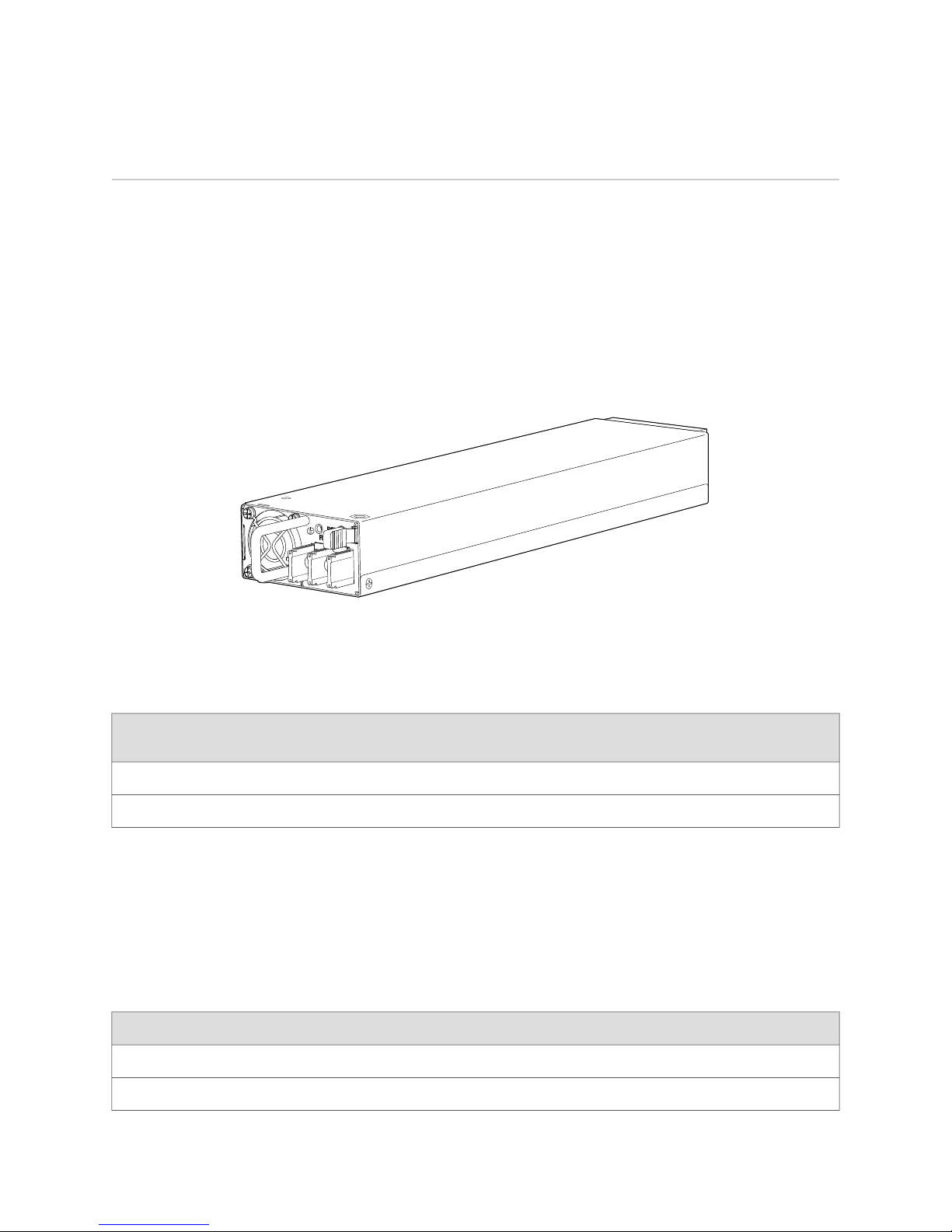
In a DC power configuration, the services gateway contains one to four DC power
supplies, located at the rear of the chassis in slots PEM0 and PEM1 (SRX 3400) or
PEM0 through PEM3 (SRX 3600). Each power supply provides power to all
components in the services gateway. When multiple power supplies are present,
they share power almost equally within a fully populated system. The multiple DC
power supplies provide power redundancy. If one power supply fails or is removed,
the remaining power supplies redistributes the electrical load without interruption.
The device reassesses the power required to support its configuration and issues
errors if the available power is insufficient.
Figure 1: DC Power Supply
Table 1 on page 2 shows the power supply support for the SRX 3400 and SRX 3600
services gateways.
Table 1: Power Supply Support
DC Power Supply Electrical Specifications
Each DC power supply has a single DC input (–48 VDC and return) that requires a
dedicated 40 A (–48 VDC) circuit breaker. Table 2 on page 2 lists the DC power
supply electrical specifications.
Table 2: DC Power Supply Electrical Specifications
SpecificationParameter
850 WMaximum output power
Minimum Number of Power
SuppliesPower Supply SlotsDevice
Maximum Number of Power
Supplies
21PEM0 and PEM1SRX 3400
42PEM0 through PEM4SRX 3600
2 ■ DC Power Supply
–40.5 to –72 VDCDC input voltage
Page 3
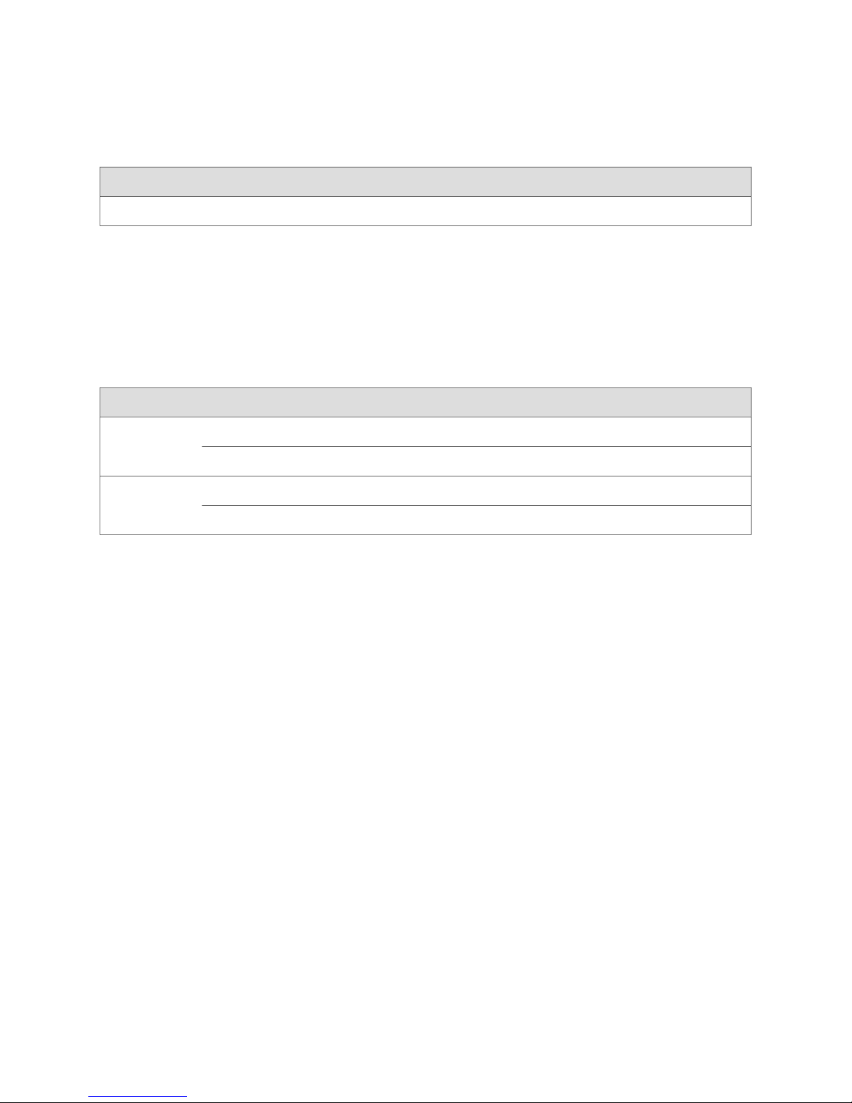
Table 2: DC Power Supply Electrical Specifications (continued)
SpecificationParameter
22.2 A @–48 VDC input current rating
For information about connecting the power supply to DC power, see “Connecting
Power to a DC-Powered Services Gateway” on page 6.
Each DC power supply faceplate displays a single LED to indicate the status of the
power supply (see Table 3 on page 3).
Table 3: DC Power Supply LED
Indicated ConditionLED StatusColor
DC Power Supply
+3V3SB is ON, +12 V
+3V3SB is ON; +12 V
FAN_FAULT, OTP, 3V3 OCP/UVPOn steadilyRed
+12 V_OCP, +12 V_UVP, +12 V OVPBlinking
OUT
OUT
is ONOn steadilyGreen
is OFF; DC is presentBlinking
DC Power Supply ■ 3
Page 4

SRX 3400 and SRX 3600 Services Gateway DC Power Supply Installation Instructions
Installing a DC Power Supply
To install a DC power supply:
4 ■ Installing a DC Power Supply
Page 5
g036085
Installing a DC Power Supply
1. Ensure that the voltage across the DC power source cable leads is 0 V and that
there is no chance that the cable leads might become active during installation.
2. Attach an electrostatic discharge (ESD) grounding strap to your bare wrist and
connect the strap to one of the ESD points on the chassis. For more information
about ESD, see “Preventing Electrostatic Discharge Damage” on page 9.
3. Orient the power supply as follows:
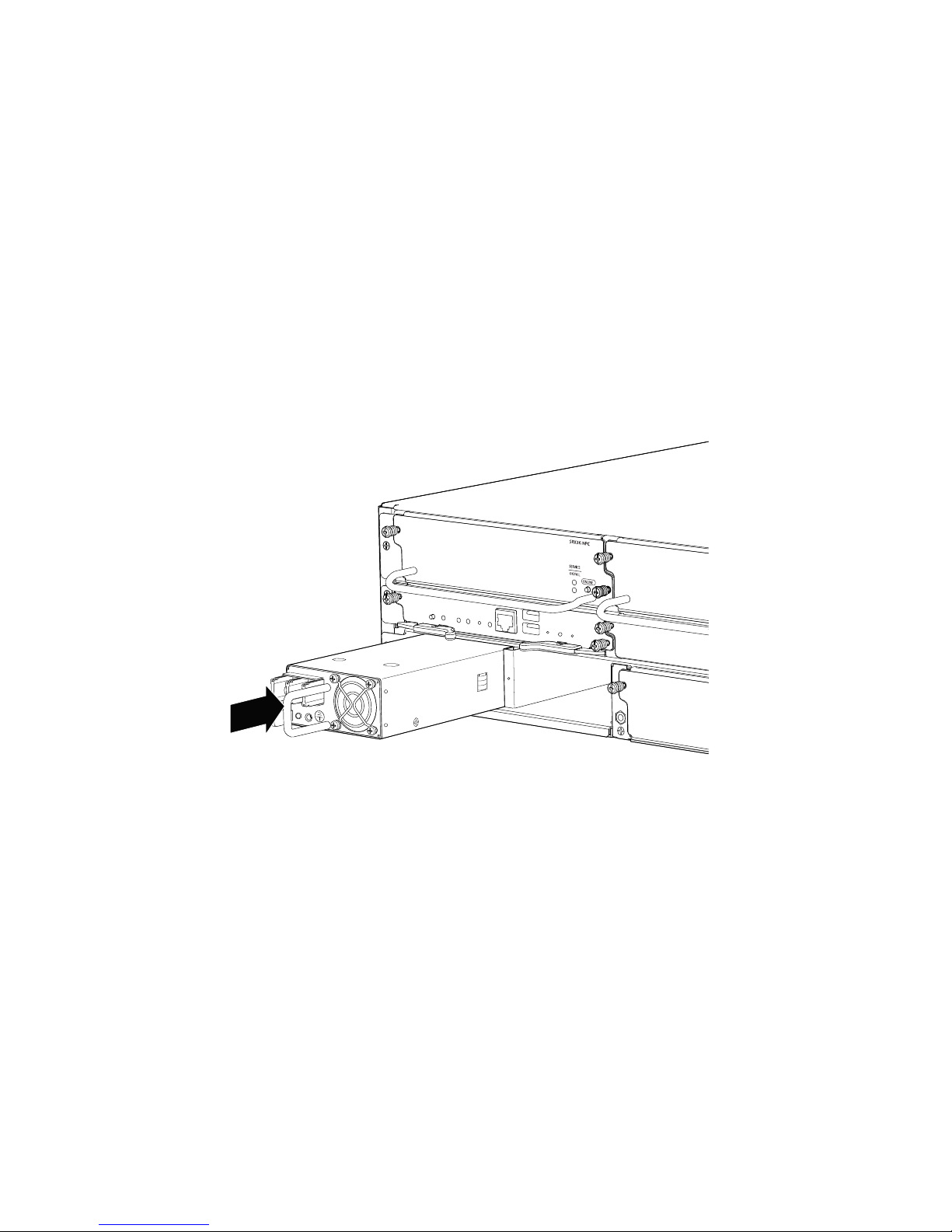
■ For SRX 3400, orient the power supply so that the locking lever is on the
left as shown in Figure 2 on page 5.
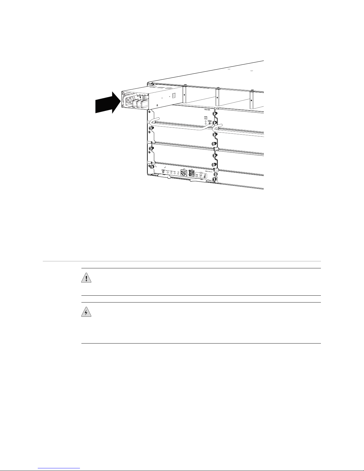
■ For SRX 3600, orient the power supply so that the locking lever is on the
right as shown in Figure 3 on page 5.
Figure 2: Installing a DC Power Supply, SRX 3400
Figure 3: Installing a DC Power Supply, SRX 3600
Installing a DC Power Supply ■ 5
Page 6
SRX 3400 and SRX 3600 Services Gateway DC Power Supply Installation Instructions
4. Using both hands, slide the power supply straight into the chassis until the power
supply is fully seated in the chassis slot. The power supply faceplate should be
flush with any adjacent power supply faceplate.
See “Connecting Power to a DC-Powered Services Gateway” on page 6 for
information on connecting the power supply to DC power.
Connecting Power to a DC-Powered Services Gateway
CAUTION: Do not mix AC and DC power supplies within the same device. Damage
to the device might occur.
WARNING: Before performing the following procedure, ensure that power is removed
from the DC circuit. To ensure that all power is off, locate the circuit breaker on the
panel board that services the DC circuit, switch the circuit breaker to the off position,
and tape the switch handle of the circuit breaker in the off position.
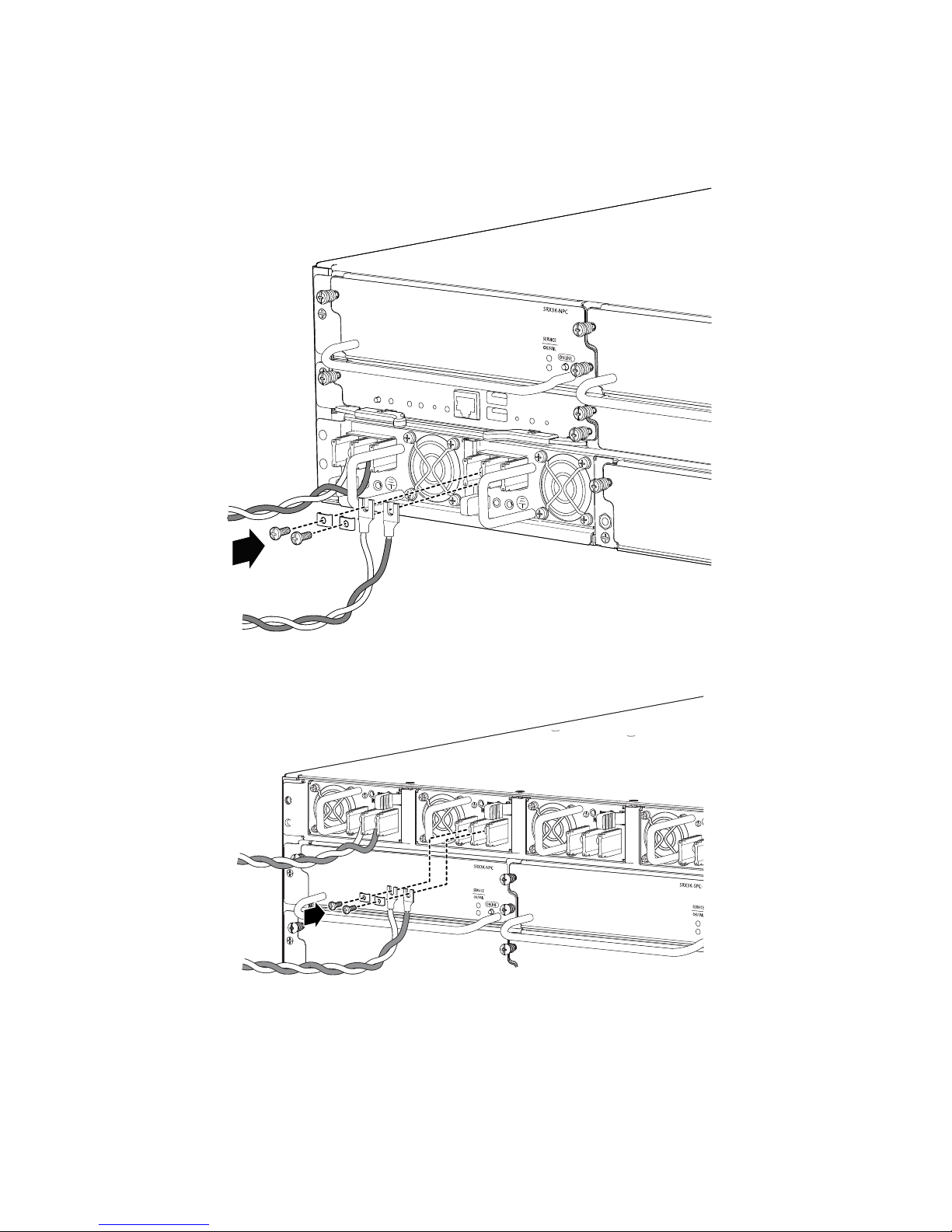
You connect DC power to the device by attaching power cables from the external
DC power sources to the terminal studs on the power supply faceplates. You must
provide the power cables (the cable lugs are supplied with the device).
To connect the DC source power cables to the device for each power supply:
1. Switch off the dedicated facility circuit breakers. Ensure that the voltage across
the DC power source cable leads is 0 V and that there is no chance that the cable
leads might become active during installation.
2. Remove the clear plastic cover protecting the terminal studs on the faceplate.
6 ■ Connecting Power to a DC-Powered Services Gateway
Page 7
Connecting Power to a DC-Powered Services Gateway
3. Verify that the DC power cables are correctly labeled before making connections
to the power supply. In a typical power distribution scheme where the return is
connected to chassis ground at the battery plant, you can use a multimeter to
verify that the ohm output of the –48V and RTN DC cables to chassis ground.
The cable with very large resistance (indicating an open circuit) to chassis ground
will be –48V and the cable with very low resistance (indicating a closed circuit)
to chassis ground will be RTN.
CAUTION: You must ensure that power connections maintain the proper polarity.
The power source cables might be labeled (+) and (–) to indicate their polarity. There
is no standard color coding for DC power cables. The color coding used by the external
DC power source at your site determines the color coding for the leads on the power
cables that attach to the terminal studs on each power supply.
4. Remove the screws and square washers from the terminals. Use a number-2
Phillips screwdriver.
5. Secure each power cable lug to the terminals, first with the square washer, then
with the screw. Apply between 23 lb-in. (2.6 Nm) and 25 lb-in. (2.8 Nm) of torque
to each screw.
■
Secure each positive (+) DC source power cable lug to a RTN (return)
terminal.
■
Secure each negative (–) DC source power cable lug to a –48V (input) terminal.
6. Replace the clear plastic cover over the terminal studs on the faceplate.
7. Verify that the power cables are connected correctly, that they are not touching
or blocking access to services gateway components, and that they do not drape
where people could trip on them.
8. If you are installing multiple power supplies, repeat steps 1 through 7 for the
other power supplies.
Connecting Power to a DC-Powered Services Gateway ■ 7
Page 8
g036010
g036045
SRX 3400 and SRX 3600 Services Gateway DC Power Supply Installation Instructions
Figure 4: Connecting to DC Power, SRX 3400
Figure 5: Connecting to DC Power, SRX 3600
8 ■ Connecting Power to a DC-Powered Services Gateway
Page 9
Preventing Electrostatic Discharge Damage
Many services gateway hardware components are sensitive to damage from static
electricity. Some components can be impaired by voltages as low as 30 V. You can
easily generate potentially damaging static voltages whenever you handle plastic or
foam packing material or if you move components across plastic or carpets. Observe
the following guidelines to minimize the potential for electrostatic discharge (ESD)
damage, which can cause intermittent or complete component failures:
■ Always use an ESD wrist strap or ankle strap, and verify that it is in direct contact
with your skin.
CAUTION: For safety, periodically check the resistance value of the ESD strap. The
measurement should be in the range of 1 to 10 Mohms.
■ When handling any component that is removed from the chassis, verify that the
equipment end of your ESD strap is attached to one of the ESD points on the
chassis, which are shown in Figure 7 on page 10 and Figure 8 on page 10.
Preventing Electrostatic Discharge Damage
■ Avoid contact between the component and your clothing. ESD voltages emitted
from clothing can still damage components.
■ When removing or installing a component, always place it component-side up
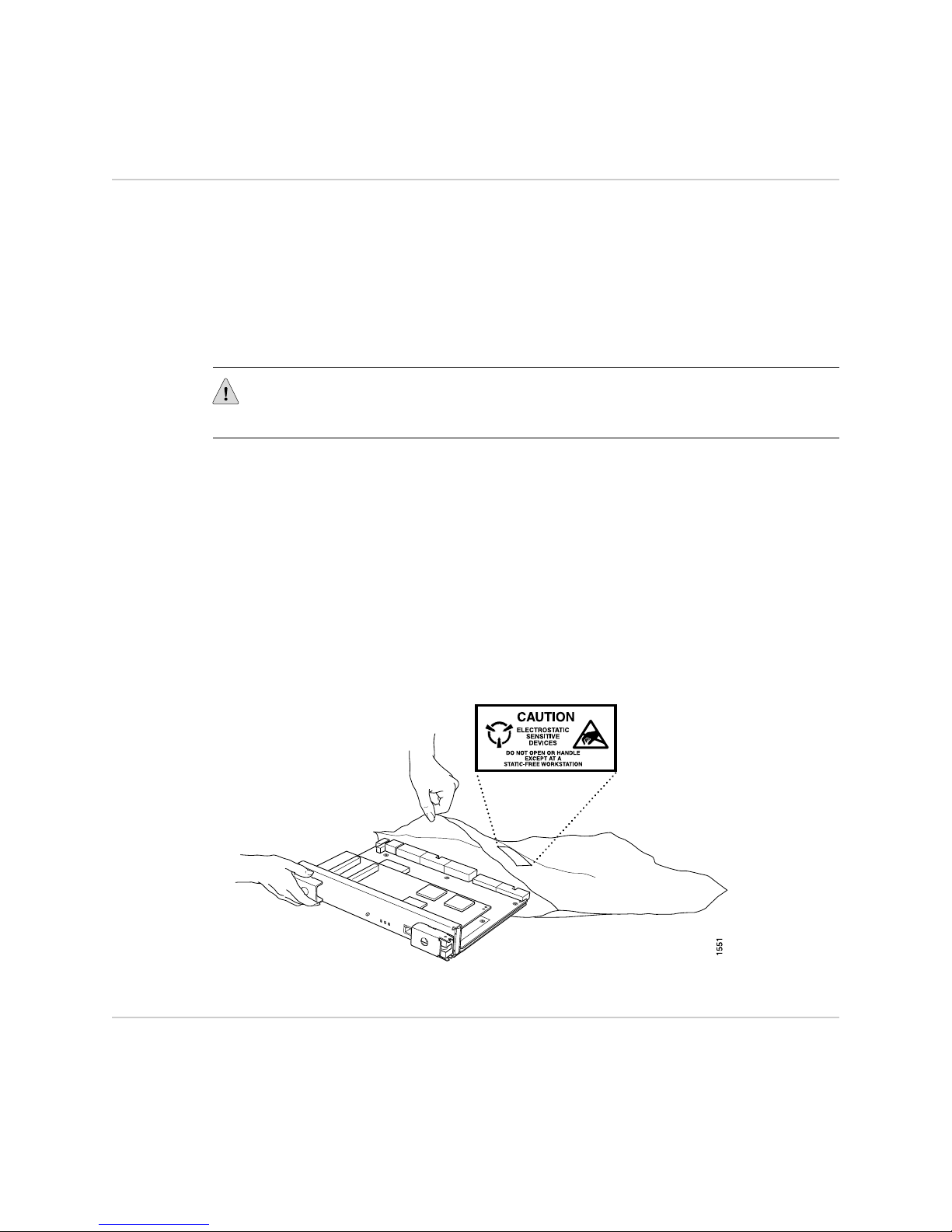
on an antistatic surface, in an antistatic card rack, or in an electrostatic bag (see
Figure 6 on page 9). If you are returning a component, place it in an electrostatic
bag before packing it.
Figure 6: Placing a Component into an Electrostatic Bag
Electrostatic Discharge Point
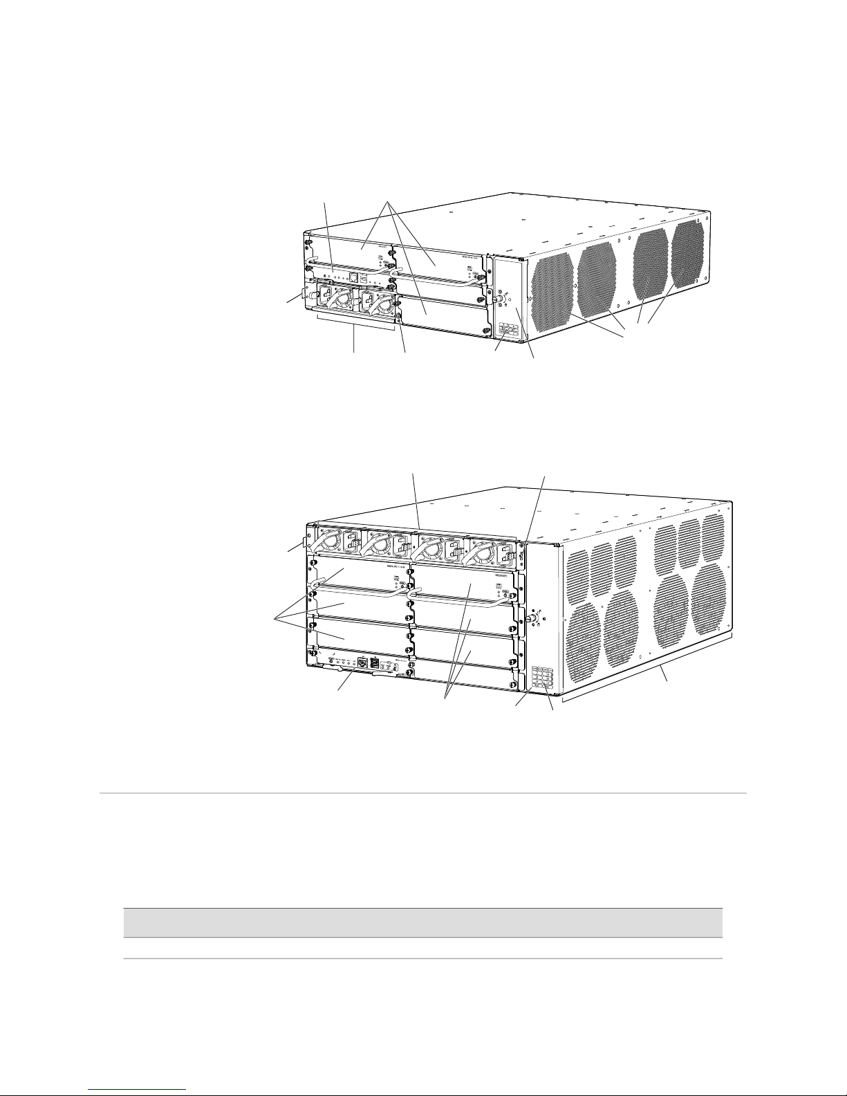
Figure 7 on page 10 and Figure 8 on page 10 show the location of the ESD point on
the rear of each chassis.
Preventing Electrostatic Discharge Damage ■ 9
Page 10
g036001
ESD
point
Power
supplies
Routing
Engine
Chassis
grounding
point
Fan tray
door
Cooling
air inlets
Slot
number
guide
CFM slots
for SPCs
and NPCs
g036036
ESD
point
Chassis
grounding
point
Fan tray
door
CFM
slots for
SPCs
Cooling
air inlets
Routing
Engine
Power
supplies
Slot
number
guide
CFM slots
for NPCs
and SPCs
SRX 3400 and SRX 3600 Services Gateway DC Power Supply Installation Instructions
Figure 7: Rear View of an SRX 3400 Services Gateway Chassis
Figure 8: Rear View of an SRX 3600 Services Gateway Chassis
List of Technical Publications
Table 4: Technical Documentation for Supported Devices
Hardware Documentation
10 ■ List of Technical Publications
Table 4 on page 10 lists the hardware guides and release notes for Juniper Networks
SRX-series services gateways and describes the contents of each document. All
documents are available at http://www.juniper.net/techpubs/.
DescriptionBook
Page 11

Table 4: Technical Documentation for Supported Devices (continued)
DescriptionBook
Requesting Technical Support
SRX 3400 Services Gateway Hardware Guide or
SRX 3600 Services Gateway Hardware Guide
Release Notes
JUNOS Software for SRX-series Services Gateway
Release Notes
Requesting Technical Support
Technical product support is available through the Juniper Networks Technical
Assistance Center (JTAC). If you are a customer with an active J-Care or JNASC support
contract, or are covered under warranty, and need postsales technical support, you
can access our tools and resources online or open a case with JTAC.
■ JTAC policies—For a complete understanding of our JTAC procedures and policies,
review the JTAC User Guide located at
http://www.juniper.net/customers/support/downloads/710059.pdf.
■ Product warranties—For product warranty information, visit
http://www.juniper.net/support/warranty/.
■ JTAC Hours of Operation —The JTAC centers have resources available 24 hours
a day, 7 days a week, 365 days a year.
Describes how to install, maintain, and troubleshoot the services
gateway and components. Each services gateway type has its own
hardware guide.
Summarizes new features and known problems for a particular
release of JUNOS software on SRX-series services gateways,
including J-Web interface features and problems. The release notes
also contain corrections and updates to the manuals and software
upgrade and downgrade procedures.
Self-Help Online Tools and Resources
For quick and easy problem resolution, Juniper Networks has designed an online
self-service portal called the Customer Support Center (CSC) that provides you with
the following features:
■
Find CSC offerings: http://www.juniper.net/customers/support/
■
Search for known bugs: http://www2.juniper.net/kb/
■
Find product documentation: http://www.juniper.net/techpubs/
■ Find solutions and answer questions using our Knowledge Base:
http://kb.juniper.net/
■ Download the latest versions of software and review release notes:
http://www.juniper.net/customers/csc/software/
■ Search technical bulletins for relevant hardware and software notifications:
https://www.juniper.net/alerts/
■ Join and participate in the Juniper Networks Community Forum:
http://www.juniper.net/company/communities/
■
Open a case online in the CSC Case Management tool: http://www.juniper.net/cm/
Requesting Technical Support ■ 11
Page 12

SRX 3400 and SRX 3600 Services Gateway DC Power Supply Installation Instructions
To verify service entitlement by product serial number, use our Serial Number
Entitlement (SNE) Tool located at https://tools.juniper.net/SerialNumberEntitlementSearch/.
Opening a Case with JTAC
You can open a case with JTAC on the Web or by telephone.
■
Use the Case Management tool in the CSC at http://www.juniper.net/cm/ .
■ Call 1-888-314-JTAC (1-888-314-5822 toll-free in the USA, Canada, and Mexico).
For international or direct-dial options in countries without toll-free numbers, visit
us at http://www.juniper.net/support/requesting-support.html.
Revision History
February 2009—530-026094-01. Revision 01 Initial Release.
Copyright © 2009, Juniper Networks, Inc. All rights reserved.
Juniper Networks, the Juniper Networks logo, JUNOS, NetScreen, ScreenOS, and Steel-Belted Radius are registered trademarks of Juniper Networks, Inc. in
the United States and other countries. JUNOSe is a trademark of Juniper Networks, Inc. All other trademarks, service marks, registered trademarks, or
registered service marks are the property of their respective owners.
Juniper Networks assumes no responsibility for any inaccuracies in this document. Juniper Networks reserves the right to change, modify, transfer, or
otherwise revise this publication without notice.
Products made or sold by Juniper Networks or components thereof might be covered by one or more of the following patents that are owned by or licensed
to Juniper Networks: U.S. Patent Nos. 5,473,599, 5,905,725, 5,909,440, 6,192,051, 6,333,650, 6,359,479, 6,406,312, 6,429,706, 6,459,579, 6,493,347,
6,538,518, 6,538,899, 6,552,918, 6,567,902, 6,578,186, and 6,590,785.
12 ■ Requesting Technical Support
 Loading...