

Page 1

SRX240 Services Gateway
Hardware Guide
Published: 2013-10-17
Copyright © 2013, Juniper Networks, Inc.
Page 2

Juniper Networks, Inc.
1194 North Mathilda Avenue
Sunnyvale, California 94089
USA
408-745-2000
www.juniper.net
Juniper Networks, Junos, Steel-Belted Radius, NetScreen, and ScreenOS are registered trademarks of Juniper Networks, Inc. in the United
States and other countries. The Juniper Networks Logo, the Junos logo, and JunosE are trademarks of Juniper Networks, Inc. All other
trademarks, service marks, registered trademarks, or registered service marks are the property of their respective owners.
Juniper Networks assumes no responsibility for any inaccuracies in this document. Juniper Networks reserves the right to change, modify,
transfer, or otherwise revise this publication without notice.
SRX240 Services Gateway Hardware Guide
Copyright © 2013, Juniper Networks, Inc.
All rights reserved. Printed in USA.
Revision History
October 2013—
The information in this document is current as of the date on the title page.
SOFTWARE LICENSE
The terms and conditions for using this software are described in the software license contained in the acknowledgment to your purchase
order or, to the extent applicable, to any reseller agreement or end-user purchase agreement executed between you and Juniper Networks.
By using this software, you indicate that you understand and agree to be bound by those terms and conditions.
Generally speaking, the software license restricts the manner in which you are permitted to use the software and may contain prohibitions
against certain uses. The software license may state conditions under which the license is automatically terminated. You should consult
the license for further details.
For complete product documentation, please see the Juniper Networks Web site at www.juniper.net/techpubs.
END USER LICENSE AGREEMENT
The Juniper Networks product that is the subject of this technical documentation consists of (or is intended for use with) Juniper Networks
software. Use of such software is subject to the terms and conditions of the End User License Agreement (“EULA”) posted at
http://www.juniper.net/support/eula.html. By downloading, installing or using such software, you agree to the terms and conditions of
that EULA.
Copyright © 2013, Juniper Networks, Inc.ii
Page 3

Table of Contents
About This Guide . . . . . . . . . . . . . . . . . . . . . . . . . . . . . . . . . . . . . . . . . . . . . . . . . . ix
Objectives . . . . . . . . . . . . . . . . . . . . . . . . . . . . . . . . . . . . . . . . . . . . . . . . . . . . . . ix
Audience . . . . . . . . . . . . . . . . . . . . . . . . . . . . . . . . . . . . . . . . . . . . . . . . . . . . . . . ix
Documentation Conventions . . . . . . . . . . . . . . . . . . . . . . . . . . . . . . . . . . . . . . . ix
SRX Series Documentation and Release Notes . . . . . . . . . . . . . . . . . . . . . . . . xi
Obtaining Documentation . . . . . . . . . . . . . . . . . . . . . . . . . . . . . . . . . . . . . . . . . xi
Documentation Feedback . . . . . . . . . . . . . . . . . . . . . . . . . . . . . . . . . . . . . . . . . xii
Requesting Technical Support . . . . . . . . . . . . . . . . . . . . . . . . . . . . . . . . . . . . . xii
Self-Help Online Tools and Resources . . . . . . . . . . . . . . . . . . . . . . . . . . . xii
Opening a Case with JTAC . . . . . . . . . . . . . . . . . . . . . . . . . . . . . . . . . . . . . xiii
Part 1 SRX240 Services Gateway Overview
Chapter 1 Introduction to the SRX240 Services Gateway . . . . . . . . . . . . . . . . . . . . . . . . . 3
SRX240 Services Gateway Description . . . . . . . . . . . . . . . . . . . . . . . . . . . . . . . . . . . 3
SRX240 Services Gateway Models . . . . . . . . . . . . . . . . . . . . . . . . . . . . . . . . . . . . . . 4
SRX240 Services Gateway Hardware Features . . . . . . . . . . . . . . . . . . . . . . . . . . . . 5
Chapter 2 SRX240 Services Gateway Hardware Components and Specifications . . . . 7
SRX240 Services Gateway Chassis . . . . . . . . . . . . . . . . . . . . . . . . . . . . . . . . . . . . . . 7
SRX240 Services Gateway Front Panel and Back Panel Views . . . . . . . . . . . . . . . . 9
SRX240 Services Gateway Front Panel . . . . . . . . . . . . . . . . . . . . . . . . . . . . . . . 9
SRX240 Services Gateway Back Panel (AC power supply models) . . . . . . . . 11
SRX240 Services Gateway Back Panel (DC Power Supply Model) . . . . . . . . . 11
SRX240 Services Gateway Built-In Interfaces . . . . . . . . . . . . . . . . . . . . . . . . . . . . . 12
SRX240 Services Gateway LEDs . . . . . . . . . . . . . . . . . . . . . . . . . . . . . . . . . . . . . . . 14
Front Panel LEDs . . . . . . . . . . . . . . . . . . . . . . . . . . . . . . . . . . . . . . . . . . . . . . . . 14
Ethernet Port LEDs . . . . . . . . . . . . . . . . . . . . . . . . . . . . . . . . . . . . . . . . . . . . . . 16
DC Power Supply Feed LEDs (SRX240 Services Gateway DC Power Supply
Model) . . . . . . . . . . . . . . . . . . . . . . . . . . . . . . . . . . . . . . . . . . . . . . . . . . . . . 17
SRX240 Services Gateway Boot Devices and Dual-Root Partitioning
Scheme . . . . . . . . . . . . . . . . . . . . . . . . . . . . . . . . . . . . . . . . . . . . . . . . . . . . . . . 18
Boot Devices . . . . . . . . . . . . . . . . . . . . . . . . . . . . . . . . . . . . . . . . . . . . . . . . . . . 18
Dual-Root Partitioning Scheme . . . . . . . . . . . . . . . . . . . . . . . . . . . . . . . . . . . . 19
SRX240 Services Gateway Power Supply . . . . . . . . . . . . . . . . . . . . . . . . . . . . . . . 20
AC Power Supply (SRX240 Services Gateway) . . . . . . . . . . . . . . . . . . . . . . . 20
DC Power Supply (SRX240 Services Gateway with DC Power Supply
Model) . . . . . . . . . . . . . . . . . . . . . . . . . . . . . . . . . . . . . . . . . . . . . . . . . . . . 20
SRX240 Services Gateway Cooling System . . . . . . . . . . . . . . . . . . . . . . . . . . . . . . 21
SRX240 Services Gateway Air Filter . . . . . . . . . . . . . . . . . . . . . . . . . . . . . . . . . . . . . 21
iiiCopyright © 2013, Juniper Networks, Inc.
Page 4

SRX240 Services Gateway Hardware Guide
Chapter 3 SRX240 Services Gateway Mini-Physical Interface Modules . . . . . . . . . . . . 23
Mini-Physical Interface Modules for the SRX240 Services Gateway . . . . . . . . . . . 23
Chapter 4 SRX240 Services Gateway Power over Ethernet Support . . . . . . . . . . . . . . 25
SRX240 Services Gateway Power over Ethernet Overview . . . . . . . . . . . . . . . . . . 25
Configuring Power over Ethernet on the SRX240 Services Gateway . . . . . . . . . . . 27
Part 2 Setting Up the SRX240 Services Gateway
Chapter 5 Preparing the Site for the SRX240 Services Gateway Installation . . . . . . . . 31
Site Preparation Checklist for the SRX240 Services Gateway . . . . . . . . . . . . . . . . 31
General Site Guidelines for Installing the SRX240 Services Gateway . . . . . . . . . . 32
SRX240 Services Gateway Rack Requirements . . . . . . . . . . . . . . . . . . . . . . . . . . . 33
Clearance Requirements forAirflow andHardware Maintenance ontheSRX240
SRX240 Services Gateway Electrical and Power Requirements . . . . . . . . . . . . . . 35
Chapter 6 Installation Overview for the SRX240 Services Gateway . . . . . . . . . . . . . . . 37
Installation Overview for the SRX240 Services Gateway . . . . . . . . . . . . . . . . . . . . 37
Chapter 7 Required Tools and Parts for Installing and Maintaining the SRX240
Services Gateway . . . . . . . . . . . . . . . . . . . . . . . . . . . . . . . . . . . . . . . . . . . . . . . . . 39
Required Tools and Parts for Installing and Maintaining the SRX240 Services
Chapter 8 Unpacking the SRX240 Services Gateway . . . . . . . . . . . . . . . . . . . . . . . . . . . . 41
Unpacking the SRX240 Services Gateway . . . . . . . . . . . . . . . . . . . . . . . . . . . . . . . 41
Verifying Parts Received with the SRX240 Services Gateway . . . . . . . . . . . . . . . . 41
Chapter 9 Installing the SRX240 Services Gateway . . . . . . . . . . . . . . . . . . . . . . . . . . . . . 43
SRX240 Services Gateway Safety Requirements, Warnings, and Guidelines . . . . 43
Preparing the SRX240 Services Gateway for Installation . . . . . . . . . . . . . . . . . . . 43
Installing the SRX240 Services Gateway . . . . . . . . . . . . . . . . . . . . . . . . . . . . . . . . 44
Replacing or Installing Mini-Physical Interface Modules in the SRX240 Services
Chapter 10 Connecting, Grounding, and Powering On the SRX240 Services
Gateway . . . . . . . . . . . . . . . . . . . . . . . . . . . . . . . . . . . . . . . . . . . . . . . . . . . . . . . . . 49
Connecting the SRX240 Services Gateway to the AC Power Source . . . . . . . . . . 49
Connecting the SRX240 Services Gateway DC Power Supply Model to a DC
Connecting and Organizing Interface Cables to the SRX240 Services
Grounding the SRX240 Services Gateway . . . . . . . . . . . . . . . . . . . . . . . . . . . . . . . 55
Powering On and Powering Off the SRX240 Services Gateway . . . . . . . . . . . . . . 57
Introduction . . . . . . . . . . . . . . . . . . . . . . . . . . . . . . . . . . . . . . . . . . . . . . . . . . . . 25
PoE Classes and Power Ratings . . . . . . . . . . . . . . . . . . . . . . . . . . . . . . . . . . . . 26
Services Gateway . . . . . . . . . . . . . . . . . . . . . . . . . . . . . . . . . . . . . . . . . . . . . . . 34
Gateway . . . . . . . . . . . . . . . . . . . . . . . . . . . . . . . . . . . . . . . . . . . . . . . . . . . . . . 39
Gateway . . . . . . . . . . . . . . . . . . . . . . . . . . . . . . . . . . . . . . . . . . . . . . . . . . . . . . . 47
Power Source . . . . . . . . . . . . . . . . . . . . . . . . . . . . . . . . . . . . . . . . . . . . . . . . . . 50
Gateway . . . . . . . . . . . . . . . . . . . . . . . . . . . . . . . . . . . . . . . . . . . . . . . . . . . . . . 54
Powering On the SRX240 Services Gateway . . . . . . . . . . . . . . . . . . . . . . . . . . 57
Powering Off the SRX240 Services Gateway . . . . . . . . . . . . . . . . . . . . . . . . . 57
Resetting the SRX240 Services Gateway . . . . . . . . . . . . . . . . . . . . . . . . . . . . 59
Copyright © 2013, Juniper Networks, Inc.iv
Page 5

Table of Contents
Chapter 11 SRX240 Services Gateway Autoinstallation . . . . . . . . . . . . . . . . . . . . . . . . . . 61
SRX240 Services Gateway Autoinstallation Overview . . . . . . . . . . . . . . . . . . . . . . 61
Chapter 12 Connecting the SRX240 Services Gateway to Management Devices . . . . 63
Connecting to the SRX240 Services Gateway Setup Wizard . . . . . . . . . . . . . . . . . 63
Connecting the SRX240 Services Gateway to the CLI . . . . . . . . . . . . . . . . . . . . . . 64
Connecting the Services Gateway to the CLI Locally . . . . . . . . . . . . . . . . . . . 65
Connecting a Services Gateway to the CLI Remotely . . . . . . . . . . . . . . . . . . . 66
Connecting the Modem at the SRX240 Services Gateway End . . . . . . . . . . . . . . . 67
Connecting the Modem to the Console Port on the SRX240 Services
Gateway . . . . . . . . . . . . . . . . . . . . . . . . . . . . . . . . . . . . . . . . . . . . . . . . . . . . . . 68
Connecting to the CLI at the User End for the SRX240 Services Gateway . . . . . . 69
Chapter 13 Performing Initial Software Configuration on the SRX240 Services
Gateway . . . . . . . . . . . . . . . . . . . . . . . . . . . . . . . . . . . . . . . . . . . . . . . . . . . . . . . . . . 71
SRX240 Services Gateway Software Configuration Overview . . . . . . . . . . . . . . . . 71
Preparing the SRX240 Services Gateway for Configuration . . . . . . . . . . . . . . 71
Understanding the Factory Default Configuration . . . . . . . . . . . . . . . . . . . . . . 72
Understanding Built-In Ethernet Ports and Initial Configuration . . . . . . . . . . . 72
Mapping the Chassis Cluster Ports . . . . . . . . . . . . . . . . . . . . . . . . . . . . . . . . . . 73
Understanding Management Access . . . . . . . . . . . . . . . . . . . . . . . . . . . . . . . . 74
Performing Initial Software Configuration on the SRX240 Services Gateway
Using the Setup Wizard . . . . . . . . . . . . . . . . . . . . . . . . . . . . . . . . . . . . . . . . . . 75
About the Setup Wizard . . . . . . . . . . . . . . . . . . . . . . . . . . . . . . . . . . . . . . . . . . 75
About the Default Setup Mode . . . . . . . . . . . . . . . . . . . . . . . . . . . . . . . . . . . . . 76
About the Guided Setup Mode . . . . . . . . . . . . . . . . . . . . . . . . . . . . . . . . . . . . . 76
Running the Setup Wizard . . . . . . . . . . . . . . . . . . . . . . . . . . . . . . . . . . . . . . . . . 77
Performing Initial Software Configuration on the SRX240 Services Gateway
Using the CLI . . . . . . . . . . . . . . . . . . . . . . . . . . . . . . . . . . . . . . . . . . . . . . . . . . . 78
Performing Initial Software Configuration on the SRX240 Services Gateway
Using the J-Web Interface . . . . . . . . . . . . . . . . . . . . . . . . . . . . . . . . . . . . . . . . 80
Establishing Basic Connectivity . . . . . . . . . . . . . . . . . . . . . . . . . . . . . . . . . . . . 81
Configuring Basic System Properties . . . . . . . . . . . . . . . . . . . . . . . . . . . . . . . . 82
SRX240 Services Gateway Secure Web Access Overview . . . . . . . . . . . . . . . . . . . 85
Part 3 Maintaining, Replacing, and Monitoring the SRX240 Services
Gateway Hardware
Chapter 14 Maintaining the SRX240 Services Gateway Hardware Components . . . . . 89
Maintaining the SRX240 Services Gateway Hardware Components . . . . . . . . . . 89
Replacing the Air Filter on the SRX240 Services Gateway . . . . . . . . . . . . . . . . . . 90
Chapter 15 Monitoring the SRX240 Services Gateway . . . . . . . . . . . . . . . . . . . . . . . . . . . 95
Monitoring Hardware Components on the SRX240 Services Gateway . . . . . . . . 95
Monitoring the SRX240 Services Gateway Chassis Using the CLI . . . . . . . . . 95
Monitoring the SRX240 Services Gateway Components Using LEDs . . . . . . 97
vCopyright © 2013, Juniper Networks, Inc.
Page 6

SRX240 Services Gateway Hardware Guide
Resetting the Configuration File When the SRX240 Services Gateway Is
Juniper Networks Technical Assistance Center . . . . . . . . . . . . . . . . . . . . . . . . . . . 106
Part 4 Appendixes
Appendix A Safety and Regulatory Compliance Information . . . . . . . . . . . . . . . . . . . . . . 109
SRX240 Services Gateway Definition of Safety Warning Levels . . . . . . . . . . . . . 109
SRX240 Services Gateway General Safety Guidelines and Warnings . . . . . . . . . . 111
SRX240 Services Gateway Fire Safety Requirements . . . . . . . . . . . . . . . . . . . . . . 115
SRX240 Services Gateway Installation Safety Guidelines and Warnings . . . . . . . 116
SRX240 Services Gateway Laser and LED Safety Guidelines and Warnings . . . . 121
SRX240 ServicesGatewayMaintenance andOperational Safety Guidelines and
SRX240 Services Gateway Electrical Safety Guidelines and Warnings . . . . . . . . 130
DC Power Electrical Safety Guidelines and Warnings . . . . . . . . . . . . . . . . . . . . . . 132
Monitoring the SRX240 Services Gateway Using Chassis Alarm
Conditions . . . . . . . . . . . . . . . . . . . . . . . . . . . . . . . . . . . . . . . . . . . . . . . . . 101
Monitoring the SRX240 Services Gateway Power System . . . . . . . . . . . . . . 103
Monitoring the SRX240 Services Gateway AC Power System . . . . . . . . 103
Monitoring the SRX240 Services Gateway DC Power System . . . . . . . . 104
Inaccessible . . . . . . . . . . . . . . . . . . . . . . . . . . . . . . . . . . . . . . . . . . . . . . . . . . . 105
Loading the Rescue Configuration on the SRX240 Services Gateway . . . . . 105
Changing the RESET CONFIG Button Behavior on the SRX240 Services
Gateway . . . . . . . . . . . . . . . . . . . . . . . . . . . . . . . . . . . . . . . . . . . . . . . . . . 106
General Safety Guidelines and Warnings . . . . . . . . . . . . . . . . . . . . . . . . . . . . . 111
Qualified Personnel Warning . . . . . . . . . . . . . . . . . . . . . . . . . . . . . . . . . . . . . . 112
Restricted Access Area Warning . . . . . . . . . . . . . . . . . . . . . . . . . . . . . . . . . . . 113
Preventing Electrostatic Discharge Damage to the Services Gateway . . . . . 114
Installation Instructions Warning . . . . . . . . . . . . . . . . . . . . . . . . . . . . . . . . . . . 116
Rack-Mounting Requirements and Warnings . . . . . . . . . . . . . . . . . . . . . . . . . 118
Laser and LED Safety Guidelines and Warnings . . . . . . . . . . . . . . . . . . . . . . . 122
General Laser Safety Guidelines . . . . . . . . . . . . . . . . . . . . . . . . . . . . . . . 122
Class 1 Laser Product Warning . . . . . . . . . . . . . . . . . . . . . . . . . . . . . . . . . 122
Class 1 LED Product Warning . . . . . . . . . . . . . . . . . . . . . . . . . . . . . . . . . . 122
Laser Beam Warning . . . . . . . . . . . . . . . . . . . . . . . . . . . . . . . . . . . . . . . . 123
Radiation from Open Port Apertures Warning . . . . . . . . . . . . . . . . . . . . 123
Warnings . . . . . . . . . . . . . . . . . . . . . . . . . . . . . . . . . . . . . . . . . . . . . . . . . . . . . 125
Safety Guidelines and Warnings . . . . . . . . . . . . . . . . . . . . . . . . . . . . . . . . . . . 125
Battery Handling Warning . . . . . . . . . . . . . . . . . . . . . . . . . . . . . . . . . . . . 125
Jewelry Removal Warning . . . . . . . . . . . . . . . . . . . . . . . . . . . . . . . . . . . . 126
Lightning Activity Warning . . . . . . . . . . . . . . . . . . . . . . . . . . . . . . . . . . . . 127
Operating Temperature Warning . . . . . . . . . . . . . . . . . . . . . . . . . . . . . . . 128
Product Disposal Warning . . . . . . . . . . . . . . . . . . . . . . . . . . . . . . . . . . . . 129
Electrical Safety Guidelines and Warnings . . . . . . . . . . . . . . . . . . . . . . . . . . . 130
In Case of Electrical Accident . . . . . . . . . . . . . . . . . . . . . . . . . . . . . . . . . 130
General Electrical Safety Guidelines and Warnings . . . . . . . . . . . . . . . . 130
Copper Conductors Warning . . . . . . . . . . . . . . . . . . . . . . . . . . . . . . . . . . . 131
DC Power Electrical Safety Guidelines . . . . . . . . . . . . . . . . . . . . . . . . . . . . . . 132
DC Power Disconnection Warning . . . . . . . . . . . . . . . . . . . . . . . . . . . . . . . . . 133
DC Power Grounding Requirements and Warning . . . . . . . . . . . . . . . . . . . . . 134
Copyright © 2013, Juniper Networks, Inc.vi
Page 7

Table of Contents
DC Power Wiring Sequence Warning . . . . . . . . . . . . . . . . . . . . . . . . . . . . . . . 135
DC Power Wiring Terminations Warning . . . . . . . . . . . . . . . . . . . . . . . . . . . . . 136
SRX240 Services Gateway Agency Approvals . . . . . . . . . . . . . . . . . . . . . . . . . . . 138
SRX240 Services Gateway Compliance Statements for EMC Requirements . . . 139
Canada . . . . . . . . . . . . . . . . . . . . . . . . . . . . . . . . . . . . . . . . . . . . . . . . . . . . . . . 139
European Community . . . . . . . . . . . . . . . . . . . . . . . . . . . . . . . . . . . . . . . . . . . 139
Japan . . . . . . . . . . . . . . . . . . . . . . . . . . . . . . . . . . . . . . . . . . . . . . . . . . . . . . . . 139
United States . . . . . . . . . . . . . . . . . . . . . . . . . . . . . . . . . . . . . . . . . . . . . . . . . . 139
SRX240 Services Gateway (DC Power Supply Model) Compliance Statements
for Network Equipment Building System (NEBS) . . . . . . . . . . . . . . . . . . . . . 140
SRX240 Services Gateway Compliance Statements for Environmental
Requirements . . . . . . . . . . . . . . . . . . . . . . . . . . . . . . . . . . . . . . . . . . . . . . . . . 140
SRX240 Services Gateway Compliance Statements for Acoustic Noise . . . . . . . 141
Appendix B SRX240 Services Gateway Power Guidelines, Requirements, and
Specifications . . . . . . . . . . . . . . . . . . . . . . . . . . . . . . . . . . . . . . . . . . . . . . . . . . . 143
SRX240 Services Gateway Site Electrical Wiring Guidelines . . . . . . . . . . . . . . . . 143
SRX240 Services Gateway AC Power Specifications and Requirements . . . . . . 145
AC Power Requirement Specifications . . . . . . . . . . . . . . . . . . . . . . . . . . . . . . 145
AC Power Cord Specifications . . . . . . . . . . . . . . . . . . . . . . . . . . . . . . . . . . . . . 145
SRX240 Services Gateway DC Power Specifications and Requirements . . . . . . 146
DC Power System Electrical Specifications . . . . . . . . . . . . . . . . . . . . . . . . . . 146
DC Power Cable Specifications . . . . . . . . . . . . . . . . . . . . . . . . . . . . . . . . . . . 146
SRX240 Services Gateway Grounding Specifications . . . . . . . . . . . . . . . . . . . . . . 147
Appendix C SRX240 Services Gateway InterfaceCable Specifications and Connector
Pinouts . . . . . . . . . . . . . . . . . . . . . . . . . . . . . . . . . . . . . . . . . . . . . . . . . . . . . . . . . 149
Interface Cable and Wire Specifications for the SRX240 Services Gateway . . . . 149
RJ-45 Connector Pinouts for the SRX240 Services Gateway Ethernet Port . . . . 149
RJ-45 Connector Pinouts for the SRX240 Services Gateway Console Port . . . . . 151
Appendix D Contacting Customer Support and Returning the SRX240 Services
Gateway Hardware . . . . . . . . . . . . . . . . . . . . . . . . . . . . . . . . . . . . . . . . . . . . . . . 153
Return Procedure for the SRX240 Services Gateway . . . . . . . . . . . . . . . . . . . . . . 153
Locating SRX240 Services Gateway Component Serial Number and Agency
Labels . . . . . . . . . . . . . . . . . . . . . . . . . . . . . . . . . . . . . . . . . . . . . . . . . . . . . . . . 154
Listing the SRX240 Services Gateway and Component Details with the
CLI . . . . . . . . . . . . . . . . . . . . . . . . . . . . . . . . . . . . . . . . . . . . . . . . . . . . . . . 154
SRX240 Services Gateway Chassis Serial Number and Agency Labels . . . . 155
SRX240 Services Gateway Mini-Physical Interface Module Serial Number
Label . . . . . . . . . . . . . . . . . . . . . . . . . . . . . . . . . . . . . . . . . . . . . . . . . . . . . 155
Contacting Customer Support to Obtain Return Materials Authorization . . . . . . 155
Information You Might Need to Supply to Juniper Networks Technical
Assistance Center . . . . . . . . . . . . . . . . . . . . . . . . . . . . . . . . . . . . . . . . . . 156
Juniper Networks Technical Assistance Center . . . . . . . . . . . . . . . . . . . . . . . 156
Packing the SRX240 Services Gateway and Components for Shipment . . . 156
Packing the Services Gateway . . . . . . . . . . . . . . . . . . . . . . . . . . . . . . . . . 157
Packing the Components for Shipment . . . . . . . . . . . . . . . . . . . . . . . . . 157
viiCopyright © 2013, Juniper Networks, Inc.
Page 8

SRX240 Services Gateway Hardware Guide
Part 5 Index
Index . . . . . . . . . . . . . . . . . . . . . . . . . . . . . . . . . . . . . . . . . . . . . . . . . . . . . . . . . . . . . 161
Copyright © 2013, Juniper Networks, Inc.viii
Page 9

About This Guide
•
Objectives on page ix
•
Audience on page ix
•
Documentation Conventions on page ix
•
SRX Series Documentation and Release Notes on page xi
•
Obtaining Documentation on page xi
•
Documentation Feedback on page xii
•
Requesting Technical Support on page xii
Objectives
This guide describes hardware components and installation, basic configuration, and
basic troubleshooting procedures for the Juniper Networks SRX240 Services Gateway.
It explains how to prepare your site for services gateway installation, unpack and install
the hardware, power on the services gateway, perform initial software configuration, and
perform routine maintenance. After completing the installation and basic configuration
procedures covered in this guide, see the Junos OS configuration guides for information
about further Junos OS configuration.
Audience
This guide is designed for network administrators who are installing and maintaining a
Juniper Networks SRX240 Services Gateway or preparing a site for device installation.
To use this guide,you needa broad understandingofnetworks ingeneral and the Internet
in particular, networking principles, and network configuration. Any detailed discussion
of these concepts is beyond the scope of this guide.
Documentation Conventions
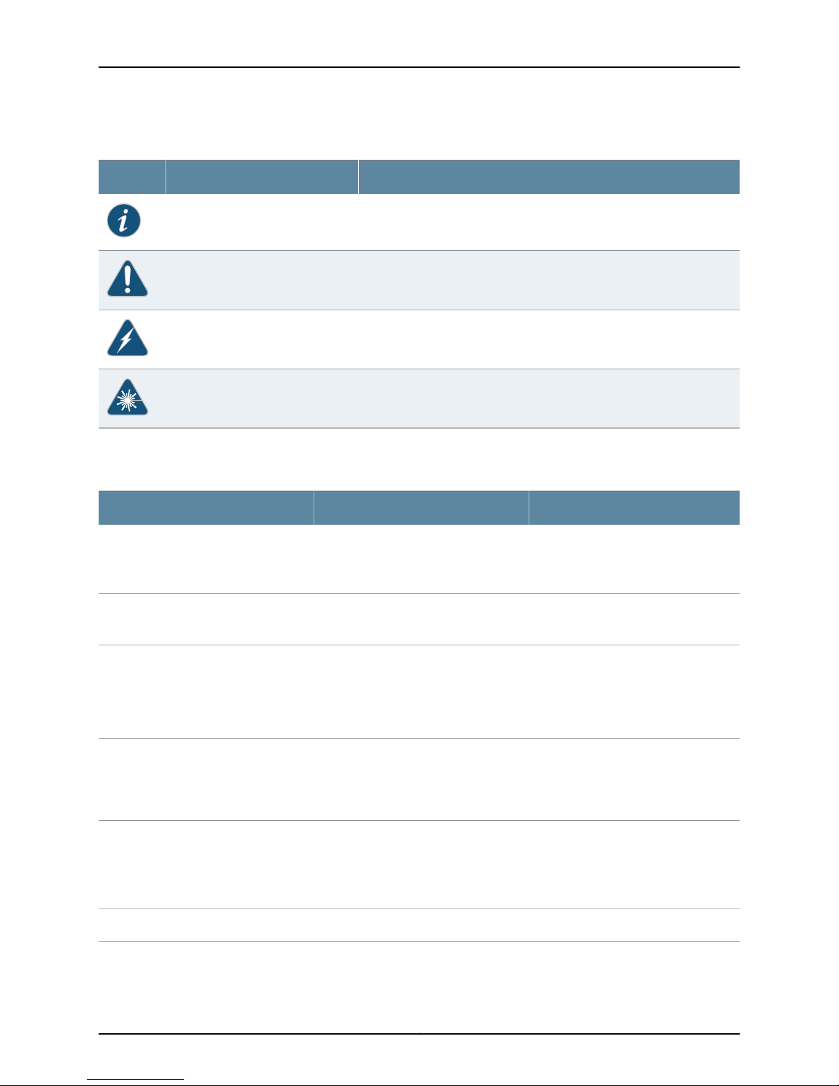
Table 1 on page x defines the notice icons used in this guide.
ixCopyright © 2013, Juniper Networks, Inc.
Page 10
SRX240 Services Gateway Hardware Guide
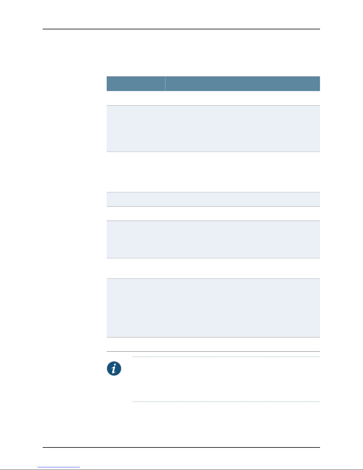
Table 1: Notice Icons
Table 2 on page x defines the text and syntax conventions used in this guide.
DescriptionMeaningIcon
Indicates important features or instructions.Informational note
Indicates a situation that might result in loss of data or hardware damage.Caution
Alerts you to the risk of personal injury or death.Warning
Alerts you to the risk of personal injury from a laser.Laser warning
Table 2: Text and Syntax Conventions
Represents text that you type.Bold text like this
Fixed-width text like this
Italic text like this
Italic text like this
Text like this
Represents output that appears on the
terminal screen.
•
Introduces or emphasizes important
new terms.
•
Identifies guide names.
•
Identifies RFC and Internetdraft titles.
Represents variables (options for which
you substitute a value) in commands or
configuration statements.
Represents names of configuration
statements, commands, files, and
directories;configurationhierarchy levels;
or labels on routing platform
components.
ExamplesDescriptionConvention
To enter configuration mode, type the
configure command:
user@host> configure
user@host> show chassis alarms
No alarms currently active
•
A policy term is a named structure
that defines match conditions and
actions.
•
Junos OS CLI User Guide
•
RFC 1997, BGP Communities Attribute
Configure the machine’s domain name:
[edit]
root@# set system domain-name
domain-name
•
To configure a stub area, include the
stub statement at the [edit protocols
ospf area area-id] hierarchy level.
•
The console portis labeled CONSOLE.
stub <default-metric metric>;Enclose optional keywords or variables.< > (angle brackets)
Copyright © 2013, Juniper Networks, Inc.x
Page 11

Table 2: Text and Syntax Conventions (continued)
About This Guide
ExamplesDescriptionConvention
| (pipe symbol)
# (pound sign)
[ ] (square brackets)
Indention and braces ( { } )
; (semicolon)
GUI Conventions
Bold text like this
Indicates a choice between the mutually
exclusivekeywords orvariables on either
side of the symbol. The set of choices is
often enclosed in parentheses for clarity.
same lineas theconfigurationstatement
to which it applies.
Enclose a variable for which you can
substitute one or more values.
Identify a level in the configuration
hierarchy.
Identifies a leaf statement at a
configuration hierarchy level.
Representsgraphical user interface (GUI)
items you click or select.
broadcast | multicast
(string1 | string2 | string3)
rsvp { # Required for dynamic MPLS onlyIndicates a comment specified on the
community name members [
community-ids ]
[edit]
routing-options {
static {
route default {
nexthop address;
retain;
}
}
}
•
In the Logical Interfaces box, select
All Interfaces.
•
To cancel the configuration, click
Cancel.
> (bold right angle bracket)
Separates levels in a hierarchy of menu
selections.
SRX Series Documentation and Release Notes
For a list of related SRX Series documentation, see
http://www.juniper.net/techpubs/hardware/srx-series-main.html.
If the information in the latest SRX Series Release Notes differs from the information in
the documentation, follow the SRX Series Release Notes.
Obtaining Documentation
To obtain the most current version of all Juniper Networks technical documentation, see
the products documentation page on the Juniper Networks website at
http://www.juniper.net/techpubs.
To order printed copies of this guide and other Juniper Networks technical documents,
contact your sales representative.
In the configuration editor hierarchy,
select Protocols>Ospf.
xiCopyright © 2013, Juniper Networks, Inc.
Page 12

SRX240 Services Gateway Hardware Guide
Copies of the Management Information Bases (MIBs) available in a software release are
included on the documentation CDs and at http://www.juniper.net.
Documentation Feedback
We encourage you to provide feedback, comments, and suggestions so that we can
improve the documentation. You can send your comments to
[email protected], or fill out the documentation feedback form at
http://www.juniper.net/techpubs/docbug/docbugreport.html. If you are using e-mail, be
sure to include the following information with your comments:
•
Document Name
•
Document part number
•
Page number
•
Software release version (not required for Network Operations Guides [NOGs])
Requesting Technical Support
Technical product support is availablethrough theJuniper Networks Technical Assistance
Center (JTAC). If you are a customer with an active J-Care or JNASC support contract,
or are covered under warranty, and need postsales technical support, you can access
our tools and resources online or open a case with JTAC.
•
JTAC policies—For a complete understanding of our JTAC procedures and policies,
review the JTAC User Guide located at
http://www.juniper.net/us/en/local/pdf/resource-guides/7100059-en.pdf.
•
Product warranties—For product warranty information, visit
http://www.juniper.net/support/warranty/.
•
JTAC Hours of Operation —The JTAC centers have resources available 24 hours a day,
7 days a week, 365 days a year.
Self-Help Online Tools and Resources
For quick and easy problem resolution, Juniper Networks has designed an online
self-service portal called the Customer Support Center (CSC) that provides you with the
following features:
•
Find CSC offerings: http://www.juniper.net/customers/support/
•
Find product documentation: http://www.juniper.net/techpubs/
•
Find solutions and answer questions using our Knowledge Base: http://kb.juniper.net/
•
Download the latest versions of software and review release notes:
http://www.juniper.net/customers/csc/software/
•
Search technical bulletins for relevant hardware and software notifications:
https://www.juniper.net/alerts/
Copyright © 2013, Juniper Networks, Inc.xii
Page 13

•
Join and participate in the Juniper Networks Community Forum:
http://www.juniper.net/company/communities/
•
Open a case online in the CSC Case Management tool: http://www.juniper.net/cm/
To verify service entitlement byproduct serial number,use ourSerial Number Entitlement
(SNE) Tool: https://tools.juniper.net/SerialNumberEntitlementSearch/
Opening a Case with JTAC
You can open a case with JTAC on the Web or by telephone.
•
Use the Case Management tool in the CSC at http://www.juniper.net/cm/.
•
Call 1-888-314-JTAC (1-888-314-5822 toll-free in the USA, Canada, and Mexico).
For international or direct-dial options in countries without toll-free numbers, visit us at
http://www.juniper.net/support/requesting-support.html
About This Guide
xiiiCopyright © 2013, Juniper Networks, Inc.
Page 14

SRX240 Services Gateway Hardware Guide
Copyright © 2013, Juniper Networks, Inc.xiv
Page 15

PART 1
SRX240 Services Gateway Overview
•
Introduction to the SRX240 Services Gateway on page 3
•
SRX240 Services Gateway Hardware Components and Specifications on page 7
•
SRX240 Services Gateway Mini-Physical Interface Modules on page 23
•
SRX240 Services Gateway Power over Ethernet Support on page 25
1Copyright © 2013, Juniper Networks, Inc.
Page 16

SRX240 Services Gateway Hardware Guide
Copyright © 2013, Juniper Networks, Inc.2
Page 17
CHAPTER 1
g037515
Introduction to the SRX240 Services
Gateway
This chapter includes the following topics:
•
SRX240 Services Gateway Description on page 3
•
SRX240 Services Gateway Models on page 4
•
SRX240 Services Gateway Hardware Features on page 5
SRX240 Services Gateway Description
The Juniper Networks SRX240 Services Gateway offers complete functionality and
flexibility for delivering secure, reliable data over IP, and provides multiple interfaces that
support WAN and LAN connectivity and Power over Ethernet (PoE).
The SRX240 ServicesGatewayprovides IP Security(IPsec), virtualprivate network (VPN),
and firewall services for small and medium-sized companies and enterprise branch and
remote offices. Additional security features include Unified Threat Management (UTM),
which consists of IPS antispam, antivirus, and Web filtering.
The SRX240 Services Gatewayruns the Juniper Networks Junos operatingsystem (Junos
OS).
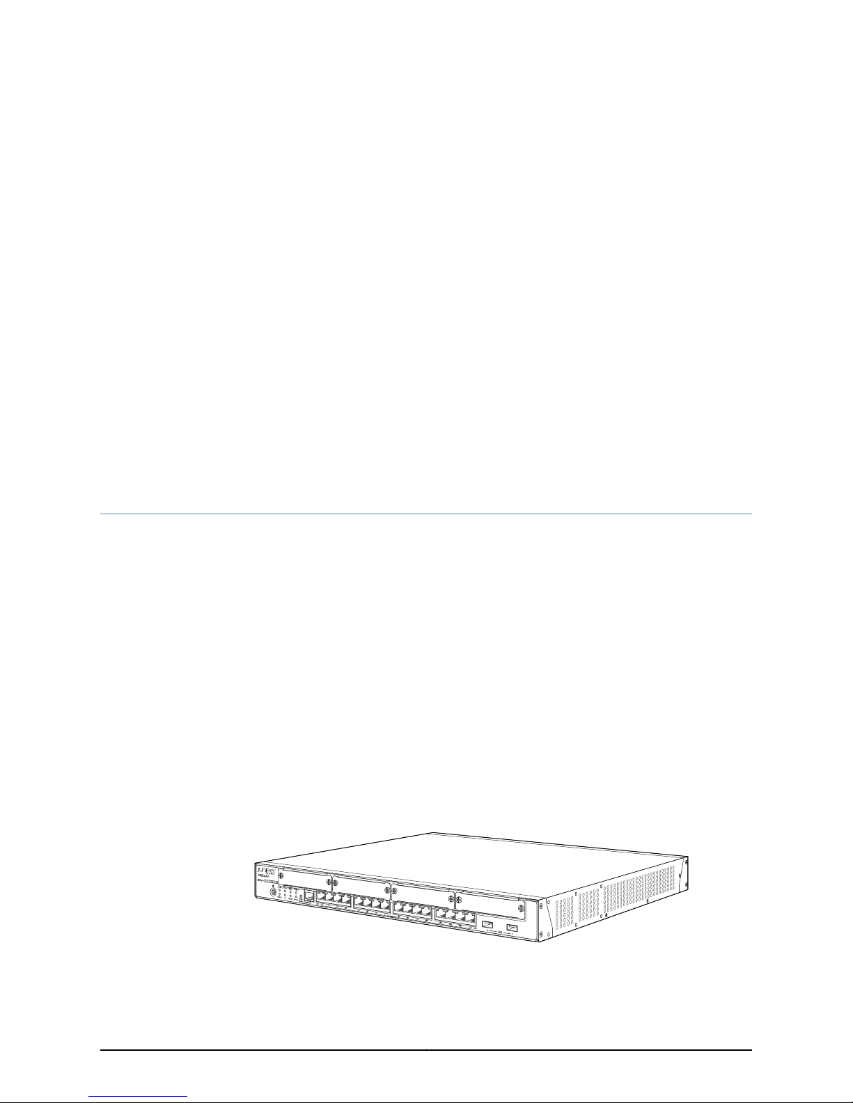
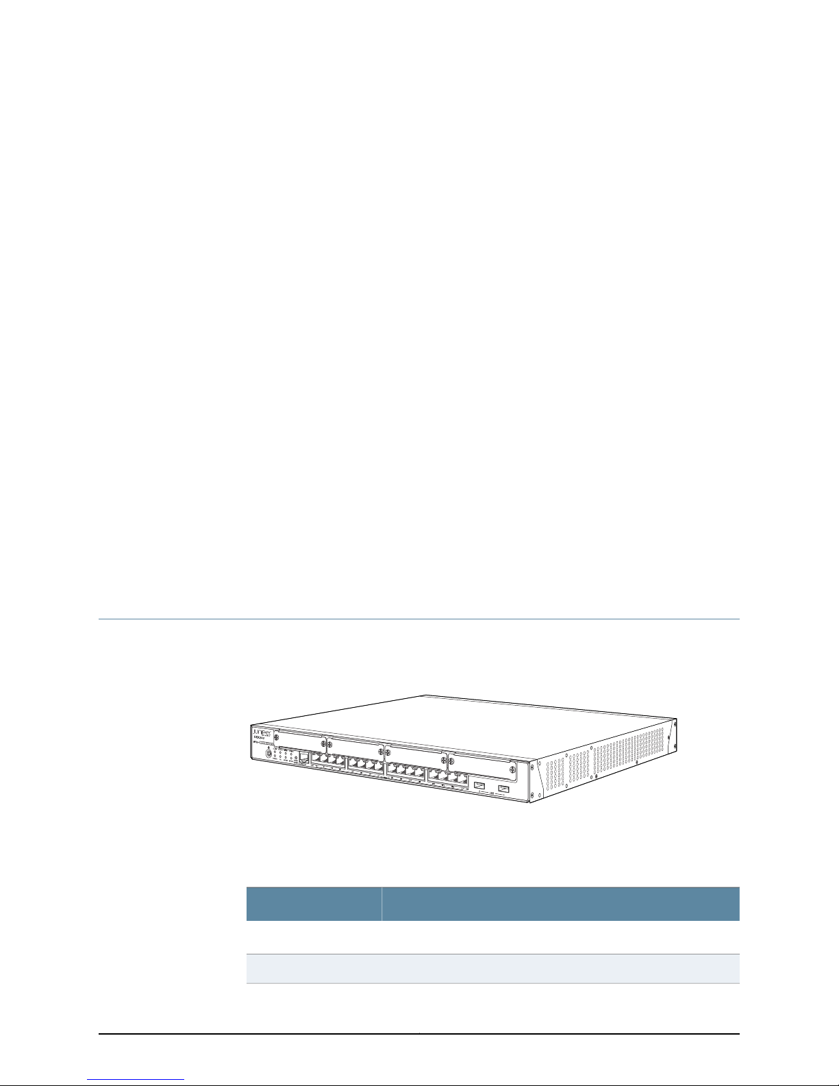
The SRX240 Services Gateway has a modular 1U chassis that fits a 19-inch rack with a
depth of approximately 17.5 in. (44.5 cm).
Figure 1 on page 3 shows the SRX240 Services Gateway.
Figure 1: SRX240 Services Gateway
3Copyright © 2013, Juniper Networks, Inc.
Page 18
SRX240 Services Gateway Hardware Guide
For information about SRX240 Services Gateway software features and licenses, see
the following guides:
•
Initial Configuration for Security Devices
•
Monitoring and Troubleshooting for Security Devices
Related
SRX240 Services Gateway Chassis on page 7•
Documentation
SRX240 Services Gateway Models
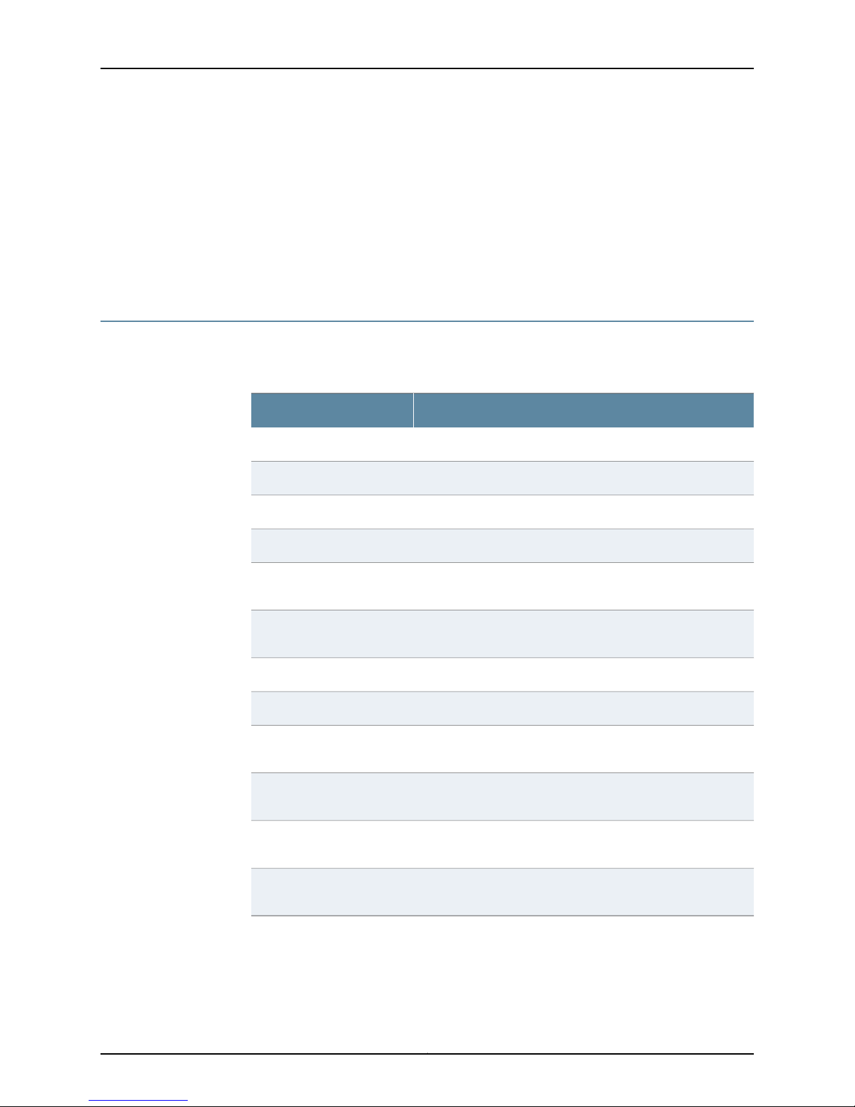
Table 3 on page 4 lists the SRX240 Services Gateway models.
Table 3: SRX240 Services Gateway Models
SRX240H-TAA
SRX240H2-TAA
Device TypeModel Name
512 MB RAM, 1 GB flash memory with AC power supplySRX240B
1 GB RAM, 2 GB flash memory with AC power supplySRX240B2
1 GB RAM, 1 GB flash memory with AC power supplySRX240H
2 GB RAM, 2 GB flash memory with AC power supplySRX240H2
1 GB RAM, 1 GB flash memory with AC power supply (TAA
compliant)
2 GB RAM, 2 GB flash memory with AC power supply (TAA
compliant)
Related
Documentation
1 GB RAM, 1 GB flash memory with DC power supplySRX240H-DC
2 GB RAM, 2 GB flash memory with DC power supplySRX240H2-DC
SRX240H-POE
SRX240H2-POE
SRX240H-POE-TAA
SRX240H2-POE-TAA
1 GB RAM, 1 GB flash memory and Power over Ethernet (PoE)
with AC power supply
2 GB RAM, 2 GB flash memory and Power over Ethernet (PoE)
with AC power supply
1 GB RAM, 1 GB flash memory and Power over Ethernet (PoE)
with AC power supply (TAA compliant)
2 GB RAM, 2 GB flash memory and Power over Ethernet (PoE)
with AC power supply (TAA compliant)
All models run Junos OS.
SRX240 Services Gateway Description on page 3•
• SRX240 Services Gateway Hardware Features on page 5
Copyright © 2013, Juniper Networks, Inc.4
Page 19

• SRX240 Services Gateway Chassis on page 7
SRX240 Services Gateway Hardware Features
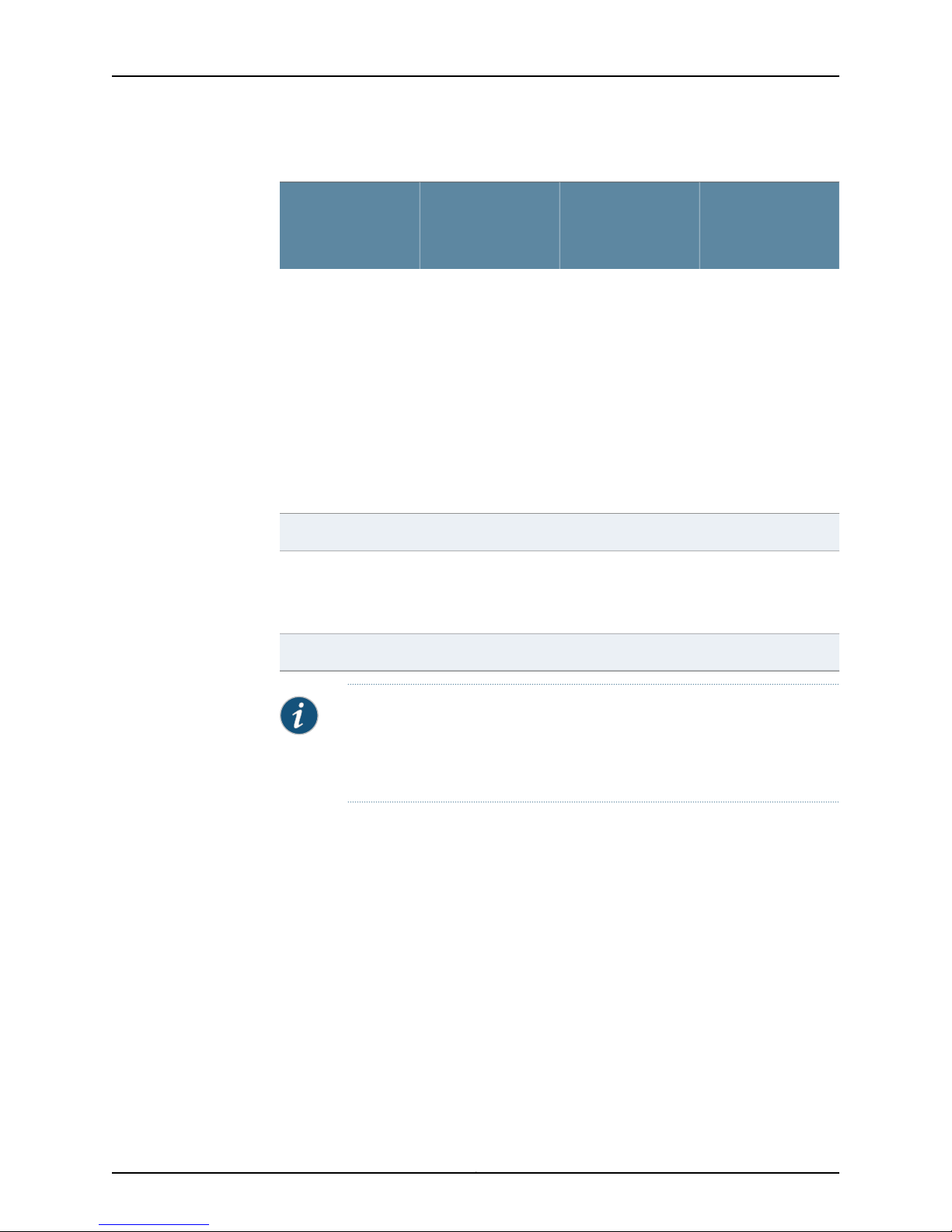
Table 4 on page 5 lists the hardware features supported on various models of the
SRX240 Services Gateway.
Table 4: SRX240 Services Gateway Hardware Features
Chapter 1: Introduction to the SRX240 Services Gateway
DDR memory
SRX240 Services
Gateway with AC
Power Supply and
No PoE SupportFeatures
•
For SRX240B:
512 MB
•
For SRX240B2:
1 GB
•
For SRX240H:
1 GB
•
For SRX240H2:
2 GB
•
For SRX240H-TAA:
1 GB
•
For
SRX240H2-TAA:
2 GB
SRX240 Services
Gateway with AC
Power Supply and
PoE Support
•
For SRX240H-POE:
1 GB
•
For
SRX240H2-POE:
2 GB
•
For
SRX240H-POE-TAA:
1 GB
•
For
SRX240H2-POE-TAA:
2 GB
100 to 240 VAC100 to 240 VACInput voltage
SRX240 Services
Gateway with DC
Power Supply
•
For SRX240H-DC:
1 GB
•
For SRX240H2-DC:
2 GB
NoYesNoPoE support
190 watts360 watts150 wattsPower supply rating
–48 VDC
Operating range:
-40.5 V to -72 V
(USB) ports
LEDs
NOTE: The PoE LED is enabled only on the PoE variant of the SRX240 Services Gateway.
Status, Alarm, HA,
Power, Mini-PIMs, and
Port (TX/RX/Link and
PoE)
Status, Alarm, HA,
Power, Mini-PIMs, and
Port (TX/RX/Link and
PoE)
161616Gigabit Ethernet ports
111Console ports
222Universal Serial Bus
444Mini-PIM slots
Status, Alarm, HA,
Power, Mini-PIMs,
Port (TX/RX/Link and
PoE), DC power feed
LEDs.
5Copyright © 2013, Juniper Networks, Inc.
Page 20
SRX240 Services Gateway Hardware Guide
Table 4: SRX240 Services Gateway Hardware Features (continued)
Internal flash
Air filters
SRX240 Services
Gateway with AC
Power Supply and
No PoE SupportFeatures
•
For SRX240B:
1 GB
•
For SRX240B2:
2 GB
•
For SRX240H:
1 GB
•
For SRX240H2:
2 GB
•
For SRX240H-TAA:
1 GB
•
For
SRX240H2-TAA:
2 GB
(Separately
orderable)
SRX240 Services
Gateway with AC
Power Supply and
PoE Support
•
For SRX240H-POE:
1 GB
•
For
SRX240H2-POE:
2 GB
•
For
SRX240H-POE-TAA:
1 GB
•
For
SRX240H2-POE-TAA:
2 GB
SRX240 Services
Gateway with DC
Power Supply
•
For SRX240H-DC:
1 GB
•
For SRX240H2-DC:
2 GB
666Fans
OneNoneOne
Related
Documentation
YesNoNoNEBS-compliant
NOTE: An air filter is not shipped with the SRX240 Services Gateway with
AC power supply models. To meet NEBS requirements, you must order the
air filter separately and install it. Contact your Juniper Networks customer
service representative for more information.
For moredetails about the chassisspecification, see “SRX240 Services Gateway Chassis”
on page 7.
• SRX240 Services Gateway Description on page 3
• SRX240 Services Gateway Chassis on page 7
Copyright © 2013, Juniper Networks, Inc.6
Page 21
CHAPTER 2
g037515
SRX240 Services Gateway Hardware
Components and Specifications
This chapter includes the following topics:
•
SRX240 Services Gateway Chassis on page 7
•
SRX240 Services Gateway Front Panel and Back Panel Views on page 9
•
SRX240 Services Gateway Built-In Interfaces on page 12
•
SRX240 Services Gateway LEDs on page 14
•
SRX240 Services Gateway Boot Devicesand Dual-RootPartitioning Scheme on page 18
•
SRX240 Services Gateway Power Supply on page 20
•
SRX240 Services Gateway Cooling System on page 21
•
SRX240 Services Gateway Air Filter on page 21
SRX240 Services Gateway Chassis
Figure 1 on page 3 shows the SRX240 Services Gateway chassis.
Figure 2: SRX240 Services Gateway
Table 5 on page 7 provides information about the physical specifications for the services
gateway.
Table 5: Physical Specifications for the SRX240 Services Gateway
ValueSpecification
1 unit (U)Chassis height
17.5 in. (44.5 cm)Chassis width
7Copyright © 2013, Juniper Networks, Inc.
Page 22
SRX240 Services Gateway Hardware Guide
Table 5: Physical Specifications for the SRX240 Services
Gateway (continued)
Chassis weight
Average Power
consumption
ValueSpecification
15 in. (38.1 cm)Chassis depth
•
SRX240 Services Gateway with AC power supply and no PoE
support models: 11.24 lb. (5.1 kg)
•
SRX240 Services Gateway with AC power supply and PoE support
models: 12.34 lb. (5.6 kg)
•
SRX240 Services Gateway with DC power supply models: 12.56 lb.
(5.7 kg)
•
SRX240 Services Gateway with AC power supply and no PoE
support models: 74 watts
•
SRX240 Services Gateway with AC power supply and PoE support:
86 watts (excluding PoE load)
•
SRX240 Services Gateway with DC power supply models: 72 watts
Temperature
Seismic
Maximum thermal
output
NOTE: Before removing or installing components of a functioning services
gateway, attach an electrostatic discharge (ESD) strap to an ESD point and
fasten the other end of the strap around your bare wrist. Failure to use an
ESD strap could result in damage to the services gateway.
No performance degradation at upto 10,000 ft (3048 m)Altitude
5% to 90%, noncondensingRelative humidity
Normal operation ensured in temperature range 32°F (0°C) through
104°F (40°C)
Nonoperating storage temperature in shipping container: -40°F
(-40°C) to 158°F (70°C)
Designed to meet Telcordia Technologies Zone 4 earthquake
requirements
•
SRX240 Services Gateway with AC power supply and no PoE
support models: 427 BTU/hour
•
SRX240 Services Gateway with AC power supply and PoE support
models: 560 BTU/hour (Excluding PoE load)
•
SRX240 Services Gateway with DC power supply models: 409
BTU/hour
NOTE: These specifications are estimates and subject to change.
Less than 70 dB(A) as per EN ISO 7779Noise level
Related
SRX240 Services Gateway Description on page 3•
Documentation
Copyright © 2013, Juniper Networks, Inc.8
Page 23
g037516
Chapter 2: SRX240 Services Gateway Hardware Components and Specifications
• SRX240 Services Gateway Hardware Features on page 5
• SRX240 Services Gateway Front Panel and Back Panel Views on page 9
• SRX240 Services Gateway Built-In Interfaces on page 12
• SRX240 Services Gateway LEDs on page 14
• SRX240 Services Gateway Power Supply on page 20
• SRX240 Services Gateway Cooling System on page 21
SRX240 Services Gateway Front Panel and Back Panel Views
This topic describes the front panel and back panel of the SRX240 Services Gateway
models. This topic includes the following sections:
•
SRX240 Services Gateway Front Panel on page 9
•
SRX240 Services Gateway Back Panel (AC power supply models) on page 11
•
SRX240 Services Gateway Back Panel (DC Power Supply Model) on page 11
SRX240 Services Gateway Front Panel
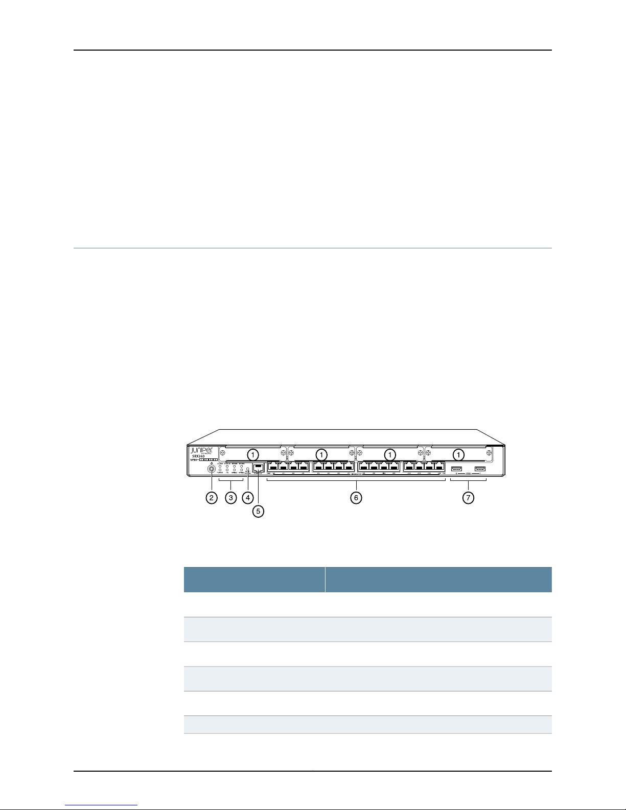
Figure 3 on page 9 shows the front panel of an SRX240 Services Gateway.
Figure 3: SRX240 Services Gateway Front Panel ( with AC Power Supply
Model, and with DC Power Supply Models)
Table 6 on page 9 lists the front panel components of the services gateway.
Table 6: SRX240 Services Gateway Front Panel
ComponentNumber
Mini-PIM slots1
Power button2
LEDs: Status, Power, Mini-PIM, Alarm, HA3
RESET CONFIG button4
Console port5
Gigabit Ethernet ports6
9Copyright © 2013, Juniper Networks, Inc.
Page 24

SRX240 Services Gateway Hardware Guide
Table 6: SRX240 Services Gateway Front Panel (continued)
For more information on the front panel components, see the following topics:
•
SRX240 Services Gateway Built-In Interfaces on page 12
•
SRX240 Services Gateway LEDs on page 14
•
SRX240 Services Gateway Boot Devicesand Dual-RootPartitioning Scheme on page 18
ComponentNumber
Universal Serial Bus (USB) ports7
Copyright © 2013, Juniper Networks, Inc.10
Page 25
g037502
g037538
1 2 3 4 5
Chapter 2: SRX240 Services Gateway Hardware Components and Specifications
SRX240 Services Gateway Back Panel (AC power supply models)
Figure 4 on page 11 shows the back panel of the SRX240 Services Gateway AC power
supply models.
Figure 4: SRX240 Services Gateway Back Panel ( with AC Power Supply
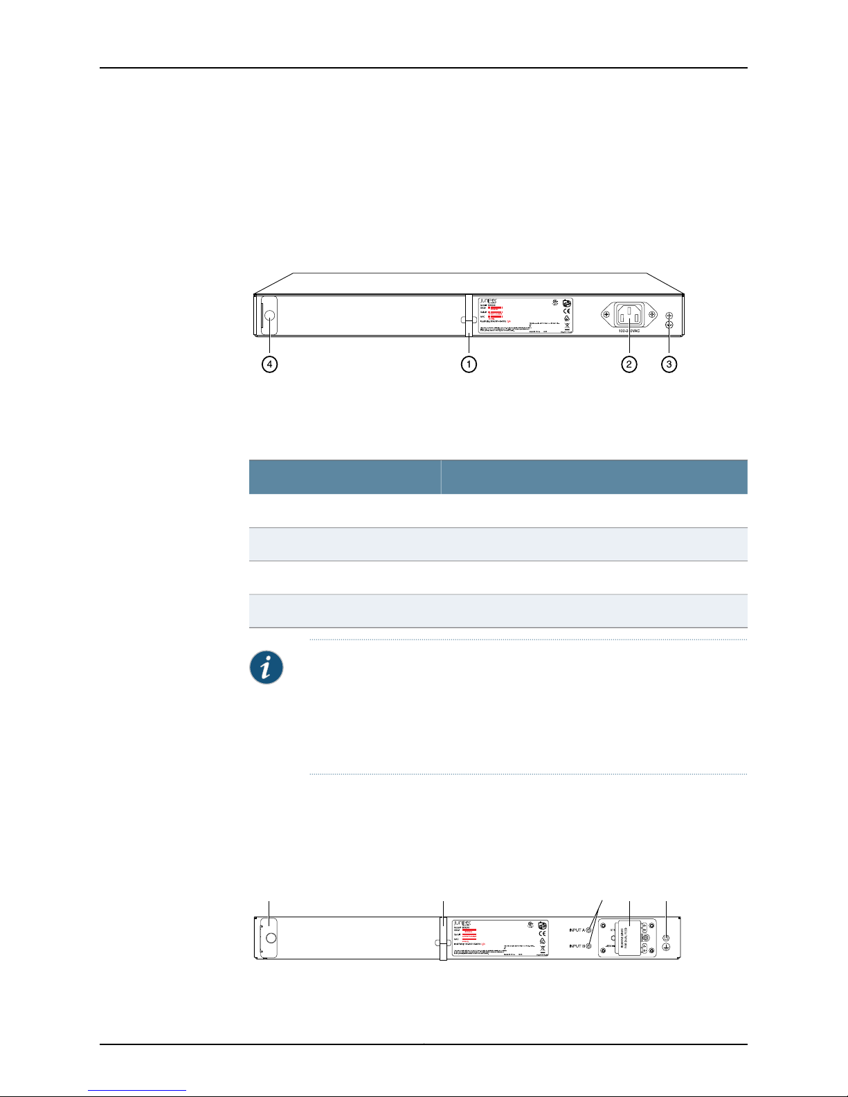
Models)
Table 7 on page 11 lists the back panel components of the SRX240 Services Gateway
AC power supply models.
Table 7: SRX240 Services Gateway Back Panel AC Power Supply Models
ComponentNumber
Cable tie holder1
Power supply point2
Grounding point3
Air filter slot4
NOTE: The air filter is shipped with SRX240 Services Gateways with DC
power supply models only.
You can order the air filter separately for the SRX240 Services Gateway with
AC power supply models. Contact your Juniper Networks customer service
representative for more information.
SRX240 Services Gateway Back Panel (DC Power Supply Model)
Figure 5on page 11 shows theback panel of an SRX240 Services Gateway with DC power
supply models.
Figure 5: SRX240 Services Gateway DC Power Supply Model
11Copyright © 2013, Juniper Networks, Inc.
Page 26
SRX240 Services Gateway Hardware Guide
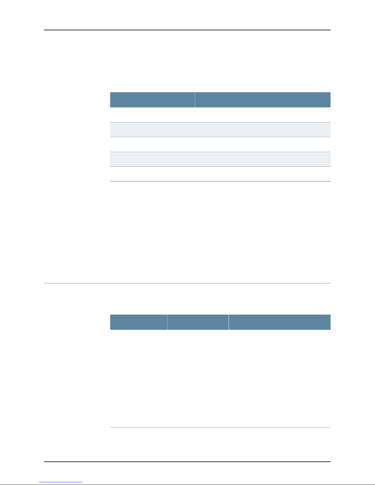
Table 8 on page 12 lists the back panel components of the SRX240 Services Gateway
DC power supply models.
Table 8: SRX240 Services Gateway Back Panel DC power supply models
ComponentNumber
Air filter slot1
Cable tie holder2
DC power feed LEDs3
DC power feed4
Grounding point5
Related
Documentation
SRX240 Services Gateway Hardware Features on page 5•
• SRX240 Services Gateway Chassis on page 7
• SRX240 Services Gateway Built-In Interfaces on page 12
• SRX240 Services Gateway LEDs on page 14
• SRX240 Services GatewayBoot Devicesand Dual-Root PartitioningScheme onpage 18
• SRX240 Services Gateway Power Supply on page 20
• SRX240 Services Gateway Cooling System on page 21
SRX240 Services Gateway Built-In Interfaces
Table 9on page12 describes the built-in interface ports on the SRX240Services Gateway.
Table 9: SRX240 Services Gateway Built-In Interfaces
•
Gigabit Ethernet
16 ports, labeled 0/0
through 0/15, built into
the chassisfront panel
•
Provide link speeds of
10/100/1000 Mbps
•
Operate in full-duplex
and half-duplex
modes
UsageDescriptionInterface Type
Function as front-end network ports and
provide LAN and WAN connectivity to hubs,
switches, local servers, and workstations.
NOTE: On the PoE
models of the SRX240
Services Gateway, all 16
Gigabit Ethernet ports
support PoE.
Copyright © 2013, Juniper Networks, Inc.12
Page 27
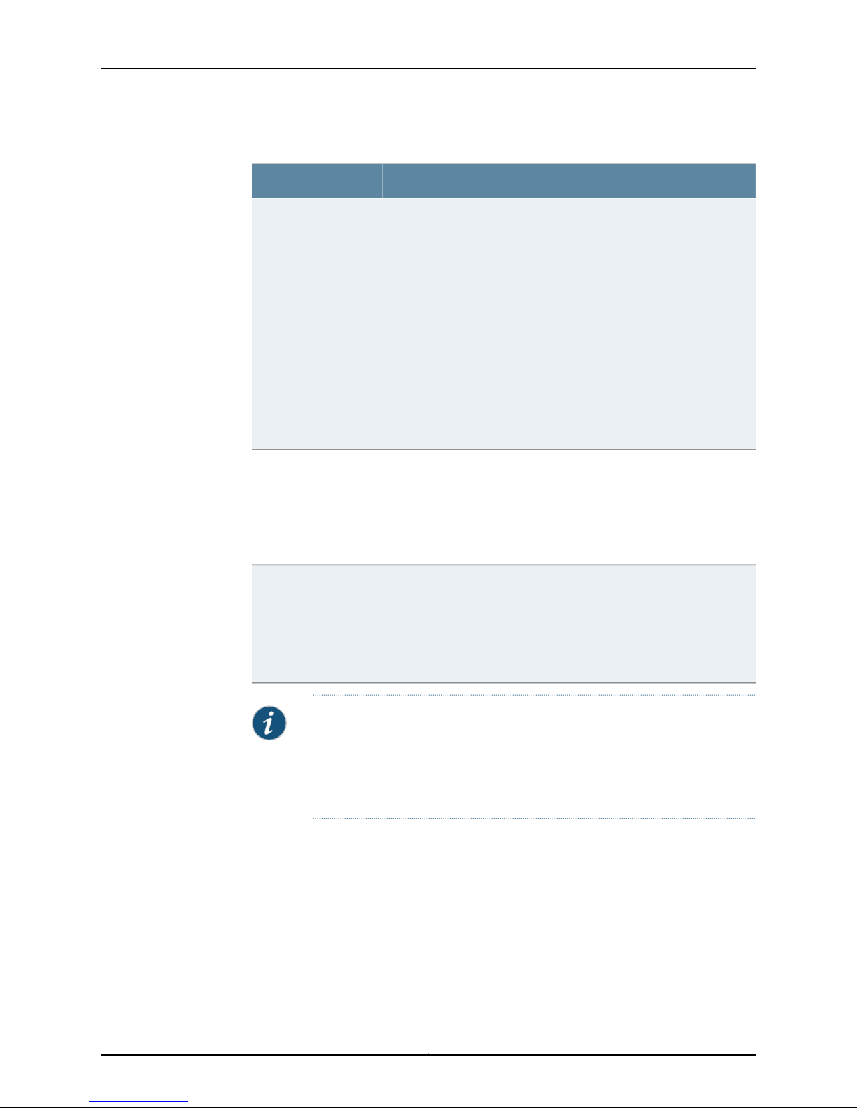
Chapter 2: SRX240 Services Gateway Hardware Components and Specifications
Table 9: SRX240 Services Gateway Built-In Interfaces (continued)
UsageDescriptionInterface Type
Universal Serial Bus
(USB)
Console
Mini-PIM slots
•
Two portslabeled,usb
0 and usb 1, built into
the chassisfront panel
•
Function in the
following modes:
•
Full speed
•
High speed
•
Compliant with USB
revision 2.0
•
One port built into the
chassis front panel
•
Uses an RJ-45 serial
cable connector
•
Supports the RS-232
(EIA-232) standard
•
Four slots built into the
chassis front panel
•
Mini-PIMs can be
plugged directly into
the slots
•
Support a USB storage device that
functions as a secondary boot device in
case of internal flash failure on startup.
NOTE: To use USB to boot your services
gateway, you must install and configure the
USB storage device on the USB port to use
it as a secondary boot device. Additionally,
the USB storage device must have Junos
OS installed.
•
Provide the USB interfaces that are used
to communicate with the various types
of Juniper Networks-supported USB
storage devices.
Contact a customer service
representative for more information.
•
Functions as a management port using
which you can log in to the services
gateway directly.
•
Provides the interface to configure the
services gateway using the CLI.
Provide LAN and WAN functionality along
with connectivity to various media types.
For more information about Mini-PIMs, see
the SRX Series Services Gateways for
the Branch Physical Interface Modules
Hardware Guide.
Related
Documentation
SRX240 Services Gateway Chassis on page 7•
• SRX240 Services Gateway Front Panel and Back Panel Views on page 9
• SRX240 Services Gateway LEDs on page 14
• SRX240 Services GatewayBoot Devicesand Dual-Root PartitioningScheme onpage 18
• SRX240 Services Gateway Power Supply on page 20
• SRX240 Services Gateway Cooling System on page 21
NOTE: We strongly recommend that only transceivers provided by Juniper
Networks be used on an SRX240 Services Gateway. We cannot guarantee
that the interface module will operate correctly if third-party transceivers
are used. Please contact Juniper Networks for the correct transceiver part
number for your device.
13Copyright © 2013, Juniper Networks, Inc.
Page 28
g037521
SRX240 Services Gateway Hardware Guide
SRX240 Services Gateway LEDs
This topic includes the following sections:
•
Front Panel LEDs on page 14
•
Ethernet Port LEDs on page 16
•
DC Power Supply Feed LEDs (SRX240 Services Gateway DC Power Supply
Model) on page 17
Front Panel LEDs
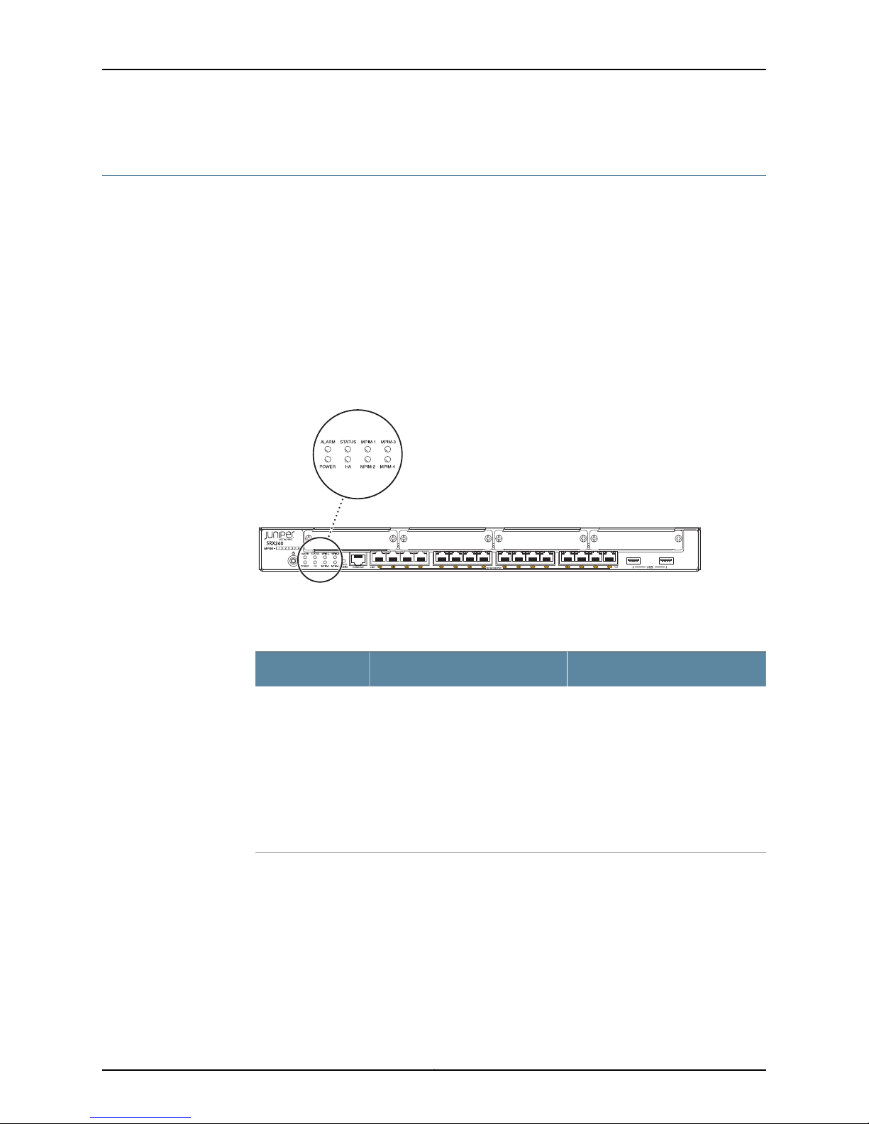
Figure 6 on page 14 shows the SRX240 Services Gateway front panel LEDs.
Figure 6: SRX240 Services Gateway Front Panel LEDs
Table 10 on page 14 lists the LED indicators onthe SRX240 Services Gateway front panel.
Table 10: SRX240 Services Gateway Front Panel Components
UsageDescriptionComponent
Status LED
The Status LED has the following
indicator colors:
•
Green and steadily on indicates
that the device is functioning
normally.
•
Amber and steadily on indicates
that the device is starting up.
•
Red and steadily on indicates that
the device has failed.
The Status LED can be used to
determine whether the device is
starting up, is functioning normally,
or has failed.
Copyright © 2013, Juniper Networks, Inc.14
Page 29

Chapter 2: SRX240 Services Gateway Hardware Components and Specifications
Table 10: SRX240 Services Gateway Front PanelComponents (continued)
UsageDescriptionComponent
Alarm LED
Power LED
HA LED
The Alarm LED has the following
indicator colors:
•
Red and steadily on indicates a
major alarm.
•
Amber and steadily on indicates
a minor alarm.
•
Off indicates that the device is
starting up.
NOTE: When the system is up and
running, if the Alarm LED is off, it
indicatesthat no alarmsare present
on the device.
The Power LED has the following
indicator colors:
•
Green and steadily on indicates
that the device is functioning
normally.
•
Amber and steadily on indicates
that the Power button has been
pressed and quickly released.
•
Off indicates that the device is
not receiving power.
The HA LED has the following
indicator colors:
•
Green and steadily on indicates
that all HA links are available.
•
Red and steadily on indicates that
the HA links are not working as
expected.
•
Amber and steadily on indicates
that some HA links are not
working as expected.
•
Off indicates that HA is not
enabled.
The Alarm LED can be used to
gatherinformation onmajor or minor
alarms or to determine whether the
device is functioning normally.
The Power LED can be used to
determine whether the device is
receiving power.
The HA LED can be used to
determine whether the chassis
clustering is enabled on the device.
Mini-PIM LED
Each Mini-Physical Interface Module
(Mini-PIM) LED has the following
indicator colors:
•
Green and steadily on indicates
that the Mini-PIM is functioning
normally.
•
Off indicates that the Mini-PIM is
not presentor not detected bythe
device.
The Mini-PIM LED can be used to
determine whether the Mini-PIM is
present and detected by the device.
15Copyright © 2013, Juniper Networks, Inc.
Page 30
g037504
SRX240 Services Gateway Hardware Guide
Ethernet Port LEDs
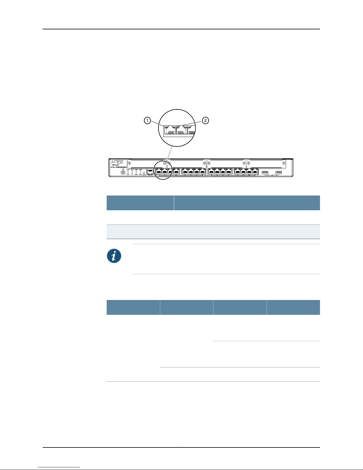
On theSRX240 Services Gateway, each Gigabit Ethernetport hasthe twoLEDs asshown
in Figure 7 on page 16.
Figure 7: SRX240 Services Gateway Port LEDs
Table 11: SRX240 Services Gateway Port LEDs
LEDNumber
TX/RX/Link LED1
PoE (Power over Ethernet) LED2
NOTE: The PoELED is enabledonly on the PoE variant of the SRX240 Services
Gateway. For non-PoE services gateways, the PoE LED remains off.
Table 12 on page 16 describes the Ethernet port LEDs.
Table 12: SRX240 Services Gateway Ethernet Port LEDs
BlinkingGreenTX/RX/Link
Steady
DescriptionStateColorFunction
Link is active. Data
communication is
taking place.
Link is active. No data
communication is
taking place.
Link is inactive.OffUnlit
Copyright © 2013, Juniper Networks, Inc.16
Page 31
g037539
LEDs
Chapter 2: SRX240 Services Gateway Hardware Components and Specifications
Table 12: SRX240 Services Gateway Ethernet Port LEDs (continued)
DescriptionStateColorFunction
SteadyGreenPoE Status
SteadyYellow
OffUnlit
PoE is activated and
the connected power
device is receiving
power.
PoE is activated, but
the connected power
device is not receiving
power (fault or not
enough power).
PoE is disabled or no
device is drawing
power.
DC Power Supply Feed LEDs (SRX240 Services Gateway DC Power Supply Model)
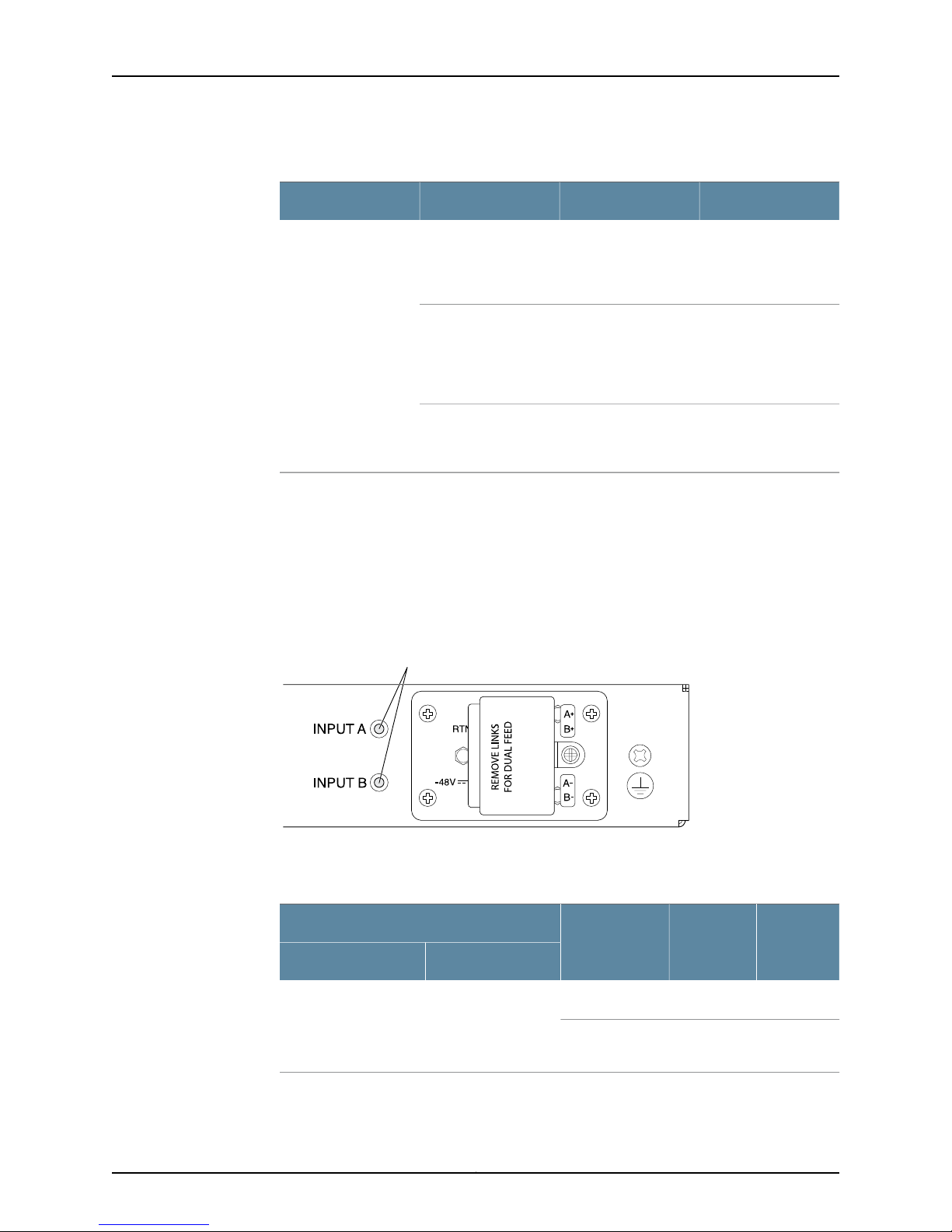
On theSRX240 Services Gatewaywith DC power supply models,the backpanel includes
two LEDs, which indicate the status of the DC power supply feed.
Figure 8 on page 17 shows the DC power supply feed LEDs on the SRX240 Services
Gateway with DC power supply model.
Figure 8: DC Power Supply Feed LEDs
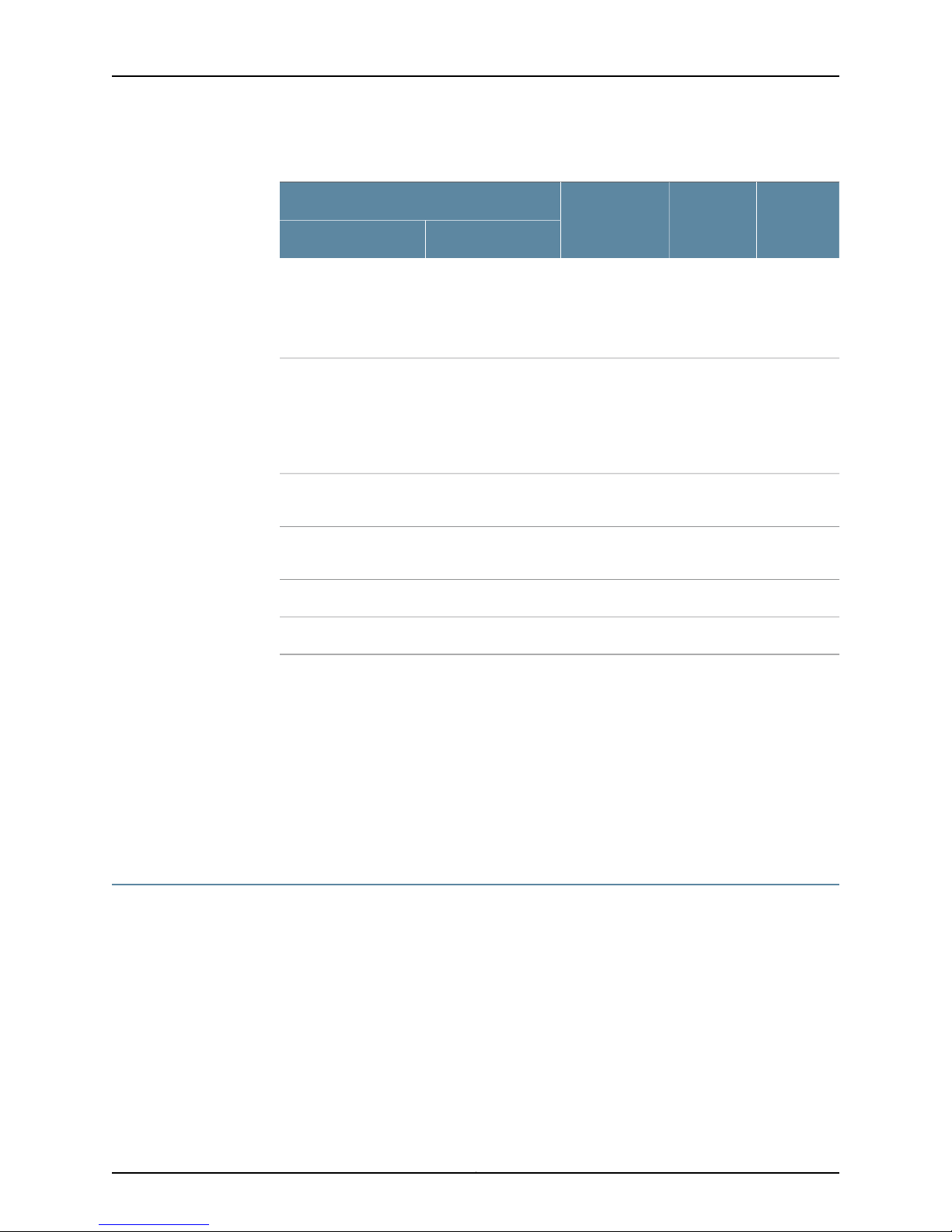
Table 13 on page 17 describes the DC power supply feed LEDs.
Table 13: DC Power Supply Feed LEDs
DC Input
Input BInput A
LED BLED ADC Output
RedRedNo output1.Input is normal.Input is normal.
GreenGreenOutput is
normal.
17Copyright © 2013, Juniper Networks, Inc.
Page 32
SRX240 Services Gateway Hardware Guide
Table 13: DC Power Supply Feed LEDs (continued)
DC Input
Related
Documentation
Input BInput A
Input is normal.Input is connected but
has failed because the
power supply fuse has
failed or input voltage
is low.
Input is normal.
no DCinput connected.
(1) No output because of output side failure or an open connection.
Input is connected
but has failed
because the power
supply fuse has failed
or input voltage is
low.
Input is normal.Input breaker open or
Output is
normal.
normal.
Output is
normal.
No output.Input has failed.Input has failed.
(blinking)
GreenOutput is
(blinking)
Red
(blinking)
SRX240 Services Gateway Chassis on page 7•
• SRX240 Services Gateway Front Panel and Back Panel Views on page 9
LED BLED ADC Output
GreenRed
Red
(blinking)
GreenRed
Red
(blinking)
OffOffNo output.No input.No input.
• SRX240 Services Gateway Built-In Interfaces on page 12
• SRX240 Services GatewayBoot Devicesand Dual-Root PartitioningScheme onpage 18
• SRX240 Services Gateway Power Supply on page 20
• SRX240 Services Gateway Cooling System on page 21
SRX240 Services Gateway Boot Devices and Dual-Root Partitioning Scheme
This topic includes the following sections:
•
Boot Devices on page 18
•
Dual-Root Partitioning Scheme on page 19
Boot Devices
The SRX240 Services Gateway can boot from the following storage media (in the given
order of priority):
•
Internal NAND flash memory (default; always present)
Copyright © 2013, Juniper Networks, Inc.18
Page 33
•
USB storage device (alternate)
Dual-Root Partitioning Scheme
Dual-root partitions allow SRX240 Services Gateways to remain functional if there is file
system corruption and facilitate easy recovery of the corrupted file system.
The dual-root partitioning scheme keeps the primary and backup Junos OS images in
two independently bootable root partitions. If the primary root partition becomes
corrupted, the system will be able to boot from the backup Junos OS image located in
the other root partition and remain fully functional.
When the services gateway powers up, it tries to boot Junos OS from the default storage
media. If the services gateway fails to boot from the default storage media, it tries to
boot from the alternate storage media. With the dual-root partitioning scheme, the
services gateway first tries to boot Junos OS from the primary root partition and then
from the backup root partition on the default storage media. The services gateway
remains fully functionaleven ifit boots Junos OS from the backup root partition of storage
media.
Chapter 2: SRX240 Services Gateway Hardware Components and Specifications
Related
Documentation
NOTE: SRX Series Services Gateways that ship with Junos OS Release 10.0
or later are formatted for the dual-root partitioning scheme.
SRX240 Services Gateways that are running Junos OS Release 9.6 or earlier use the
single-root partitioning scheme. While upgrading these services gateway to Junos OS
Release 10.0 or later, youcan choose to format the storage media with dual-root partitions
(strongly recommended) or retain the existing single-root partitioning.
For instructions on upgrading to Junos OS Release 10.0 or later, see the following guides:
•
Initial Configuration for Security Devices
•
Monitoring and Troubleshooting for Security Devices
SRX240 Services Gateway Chassis on page 7•
• SRX240 Services Gateway Front Panel and Back Panel Views on page 9
• SRX240 Services Gateway Built-In Interfaces on page 12
• SRX240 Services Gateway LEDs on page 14
• SRX240 Services Gateway Power Supply on page 20
• SRX240 Services Gateway Cooling System on page 21
19Copyright © 2013, Juniper Networks, Inc.
Page 34
SRX240 Services Gateway Hardware Guide
SRX240 Services Gateway Power Supply
This topic includes the following sections:
•
AC Power Supply (SRX240 Services Gateway) on page 20
•
DC Power Supply (SRX240Services Gatewaywith DC Power Supply Model)on page20
AC Power Supply (SRX240 Services Gateway)
The SRX240 Services Gateway AC power supply models use a fixed, internal AC power
supply. The power supply distributes the different output voltages to the device
components according to their voltage requirements. The power supply is fixed in the
chassis and is not field-replaceable.
The AC power supply has a single AC appliance inlet that requires a dedicated AC power
feed.
DC Power Supply (SRX240 Services Gateway with DC Power Supply Model)
Related
Documentation
The SRX240 Services Gateway with DC power supply models have a fixed, internal DC
power supply. The DC power supply available on the back panel of the chassis has dual
redundant power feeds and provides full power redundancy in the device. The power
supply is fixed in the chassis and is not field-replaceable.
The DC power supply feed has a terminal block that provides a single DC input (-48 VDC
and return) and requires a dedicated 10 A (-48 VDC) circuit breaker. The DC power feed
includes two LEDs that indicate the status of the power supply. For more details about
the LEDs, see “SRX240 Services Gateway LEDs” on page 14.
NOTE: Each power feed requires its own dedicated circuit breaker to be a
fully redundant DC source.
NOTE: DC-powered devices are intended for installation only in a restricted
access location.
Connecting the SRX240 Services Gateway DC Power Supply Model to a DC Power
•
Source on page 50
• SRX240 Services Gateway DC Power Specifications and Requirements on page 146
• DC Power Electrical Safety Guidelines and Warnings on page 132
• SRX240 Services Gateway Chassis on page 7
• SRX240 Services Gateway Front Panel and Back Panel Views on page 9
• SRX240 Services Gateway Built-In Interfaces on page 12
• SRX240 Services Gateway LEDs on page 14
Copyright © 2013, Juniper Networks, Inc.20
Page 35
Chapter 2: SRX240 Services Gateway Hardware Components and Specifications
SRX240 Services Gateway Cooling System
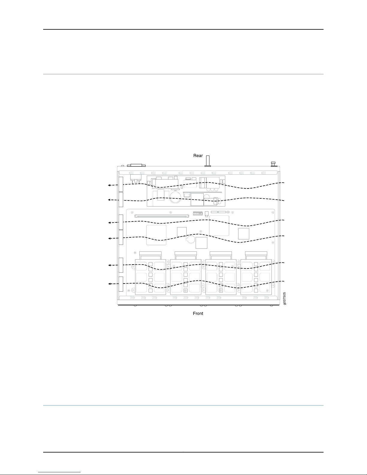
SRX240 Services Gateways have six cooling fans.
The fans draw air from the right side of the chassis (when the chassis is viewed from the
front) and exhaust the air at the left side of the chassis (when the chassis is viewed from
the front) as shown in Figure 9 on page 21.
The airflow produced by these fans keeps all components within the acceptable
temperature range.
Figure 9: Airflow Through the SRX240 Services Gateway Chassis
Related
Documentation
SRX240 Services Gateway Chassis on page 7•
• SRX240 Services Gateway Front Panel and Back Panel Views on page 9
• SRX240 Services Gateway Built-In Interfaces on page 12
• SRX240 Services Gateway LEDs on page 14
• SRX240 Services GatewayBoot Devicesand Dual-Root PartitioningScheme onpage 18
• SRX240 Services Gateway Power Supply on page 20
SRX240 Services Gateway Air Filter
The air filter for the SRX240 Services Gateway (both with AC power supply models and
with DCpower supply models) is hot-insertableand hot-removable. The airintake opening
21Copyright © 2013, Juniper Networks, Inc.
Page 36

SRX240 Services Gateway Hardware Guide
is at the right side of the chassis (when the chassis is viewed from the front side). The
air filter weighs approximately 0.2 lbs (0.09 kg). To ensure optimal operation, you must
replace the air filter periodically (every six months).
NOTE: An air filter is not shipped with the SRX240 Services Gateway with
AC power supply model. To meet NEBS requirements, you must order the air
filterseparatelyand install it. Contact your Juniper Networks customerservice
representative for more information.
Related
Documentation
• Replacing the Air Filter on the SRX240 Services Gateway on page 90
• SRX240 Services Gateway Chassis on page 7
• SRX240 Services Gateway Front Panel and Back Panel Views on page 9
• SRX240 Services Gateway LEDs on page 14
• SRX240 Services GatewayBoot Devicesand Dual-Root PartitioningScheme onpage 18
• SRX240 Services Gateway Power Supply on page 20
Copyright © 2013, Juniper Networks, Inc.22
Page 37

CHAPTER 3
SRX240 Services Gateway Mini-Physical
Interface Modules
This chapter includes the following topic:
•
Mini-Physical Interface Modules for the SRX240 Services Gateway on page 23
Mini-Physical Interface Modules for the SRX240 Services Gateway
SRX240 Services Gateway support Mini-Physical Interface Modules (Mini-PIMs).
A Mini-PIM is a network interface card (NIC) that is installed on the services gateways
to provide physical connections to a LAN or a WAN. The Mini-PIM receives incoming
packets from the network and transmits outgoing packets to the network.
The Mini-PIMs supported on SRX240 Services Gateways are field-replaceable—you can
remove and replace them. You can install a Mini-PIM in the Mini-PIM slots on the front
panel of the services gateway chassis.
Related
Documentation
CAUTION: The Mini-PIMs for SRX240 Services Gateways are not
hot-swappable. You must power off the services gateway before removing
or installing Mini-PIMs.
For more information about supported Mini-PIMs, and on how to install and configure
Mini-PIMs, refer to the SRX Series Services Gateways for the Branch Physical Interface
Modules Hardware Guide
• SRX240 Services Gateway Chassis on page 7
• SRX240 Services Gateway Front Panel and Back Panel Views on page 9
• SRX240 Services Gateway LEDs on page 14
• SRX240 Services Gateway Built-In Interfaces on page 12
• SRX240 Services Gateway Cooling System on page 21
23Copyright © 2013, Juniper Networks, Inc.
Page 38

SRX240 Services Gateway Hardware Guide
Copyright © 2013, Juniper Networks, Inc.24
Page 39

CHAPTER 4
SRX240 Services Gateway Power over
Ethernet Support
This chapter includes the following topics:
•
SRX240 Services Gateway Power over Ethernet Overview on page 25
•
Configuring Power over Ethernet on the SRX240 Services Gateway on page 27
SRX240 Services Gateway Power over Ethernet Overview
This topic includes the following sections:
•
Introduction on page 25
•
PoE Classes and Power Ratings on page 26
Introduction
Power over Ethernet (PoE) provides a device the capability to transmit both data and
electric power over a copper Ethernet LAN cable.
The PoE-capable models of the SRX240 Services Gateway (see “SRX240 Services
Gateway Models” on page 4) PoE on all Gigabit Ethernet ports. The PoE ports transfer
electrical power and data, to remote devices over a standard twisted-pair cable in an
Ethernet network. PoE ports allow you to plug in devices that require both network
connectivity and electricpower,such aswireless LAN accesspoints, and VoIP telephones.
You can configure the services gateway to act as power sourcing equipment for devices
connected to the PoE ports.
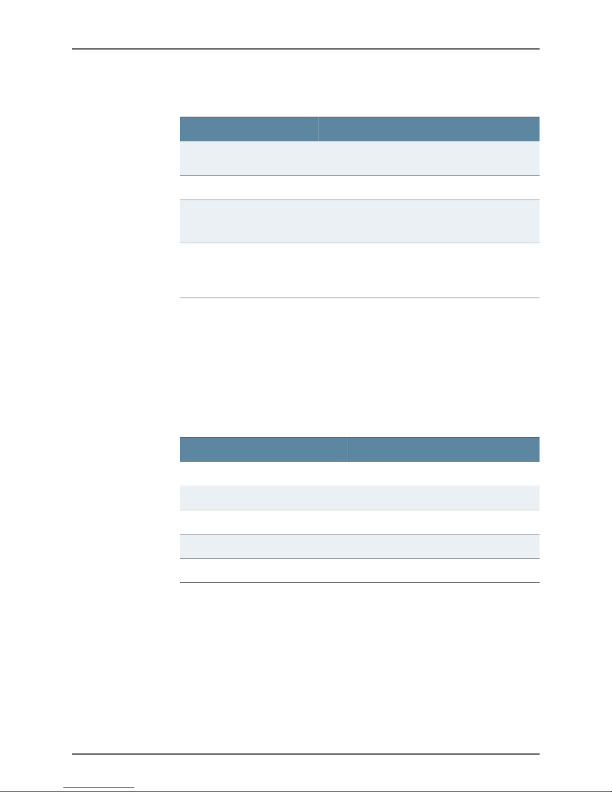
Table 14 on page 25 lists the PoE specifications for SRX240 Services Gateway.
Table 14: SRX240 Services Gateway PoE Specifications
ValuesPower Management Schemes
•
Supported standards
IEEE 802.3 AF
•
IEEE 802.3 AT (PoE+)
•
Legacy (pre-standards)
25Copyright © 2013, Juniper Networks, Inc.
Page 40
SRX240 Services Gateway Hardware Guide
Table 14: SRX240 Services Gateway PoE Specifications (continued)
ValuesPower Management Schemes
Supported ports
Per port power limit
Power management modes
PoE Classes and Power Ratings
A powered device is classified on the basis of the maximum power that it draws across
all input voltages and operational modes. When class-based power management mode
is configured onthe servicesgateway,power isallocatedtaking into account the maximum
power ratings defined for the different classes of devices.
Table 15 on page 26 lists the classes and their power ratings as specified by the IEEE
802.3 AF standard.
Table 15: PoE Classes and Power Ratings
PoE is supported on all 16 Gigabit Ethernet ports (0/0
through 0/15; interfaces ge-0/0/0 through ge-0/0/15)
150 wattsTotal PoE power sourcing capacity
30 watts
NOTE: Default value is 15.4 watts
•
Static: Power allocated for each interface can be
configured.
•
Class: Power allocated for interfaces is decided on the
basis of class of powered device connected.
Related
Documentation
Minimum Power Level Output from PoE PortClass
15.4 watts0
4.0 watts1
7.0 watts2
15.4 watts3
30.0 watts4
SRX240 Services Gateway Description on page 3•
• SRX240 Services Gateway Chassis on page 7
• SRX240 Services Gateway Front Panel and Back Panel Views on page 9
• SRX240 Services Gateway Built-In Interfaces on page 12
• SRX240 Services Gateway LEDs on page 14
• Mini-Physical Interface Modules for the SRX240 Services Gateway on page 23
Copyright © 2013, Juniper Networks, Inc.26
Page 41

Chapter 4: SRX240 Services Gateway Power over Ethernet Support
Configuring Power over Ethernet on the SRX240 Services Gateway
To enable the PoE support on your SRX240 services gateway to work properly, you must
configure the services gateway.
You can configure PoE using Junos OS CLI.
For more details on configuring the PoE, see the Interfaces for Security Devices.
Related
Documentation
• SRX240 Services Gateway Power over Ethernet Overview on page 25
• SRX240 Services Gateway Description on page 3
• SRX240 Services Gateway Built-In Interfaces on page 12
• SRX240 Services Gateway LEDs on page 14
27Copyright © 2013, Juniper Networks, Inc.
Page 42

SRX240 Services Gateway Hardware Guide
Copyright © 2013, Juniper Networks, Inc.28
Page 43

PART 2
Setting Up the SRX240 Services Gateway
•
Preparing the Site for the SRX240 Services Gateway Installation on page 31
•
Installation Overview for the SRX240 Services Gateway on page 37
•
Required Tools and Parts for Installing and Maintaining the SRX240 Services
Gateway on page 39
•
Unpacking the SRX240 Services Gateway on page 41
•
Installing the SRX240 Services Gateway on page 43
•
Connecting, Grounding, and Powering On the SRX240 Services Gateway on page 49
•
SRX240 Services Gateway Autoinstallation on page 61
•
Connecting the SRX240 Services Gateway to Management Devices on page 63
•
Performing Initial Software Configuration on the SRX240 Services Gateway on page 71
29Copyright © 2013, Juniper Networks, Inc.
Page 44

SRX240 Services Gateway Hardware Guide
Copyright © 2013, Juniper Networks, Inc.30
Page 45

CHAPTER 5
Preparing the Site for the SRX240
Services Gateway Installation
This chapter includes the following topics:
•
Site Preparation Checklist for the SRX240 Services Gateway on page 31
•
General Site Guidelines for Installing the SRX240 Services Gateway on page 32
•
SRX240 Services Gateway Rack Requirements on page 33
•
Clearance Requirements for Airflow and Hardware Maintenance onthe SRX240Services
Gateway on page 34
•
SRX240 Services Gateway Electrical and Power Requirements on page 35
Site Preparation Checklist for the SRX240 Services Gateway
The checklist in Table 16 on page 31 summarizes the tasks you need to perform when
preparing a site for installing the SRX240 Services Gateway.
Table 16: Site Preparation Checklist for Services Gateway Installation
Date
and
NotesAdditional InformationItem or Task
Environment
Verify that environmental factors such as
temperature and humidity do not exceed
device tolerances.
Power
Measure distance between external power
sources and device installation site.
Locate sites for connection of system
grounding.
Gather the AC power requirements.
“SRX240 Services Gateway Chassis”
on page 7
“SRX240 Services Gateway Electrical
and Power Requirements” on page 35
“SRX240 Services Gateway Grounding
Specifications” on page 147
“SRX240 Services Gateway AC Power
Specifications and Requirements” on
page 145
31Copyright © 2013, Juniper Networks, Inc.
Page 46

SRX240 Services Gateway Hardware Guide
Table 16: Site Preparation Checklist for Services Gateway
Installation (continued)
Date
and
NotesAdditional InformationItem or Task
Related
Documentation
Gather the DC power requirements.
“SRX240 Services Gateway DC Power
Specifications and Requirements” on
page 146
Rack Installation
•
Verify that your rack meets the minimum
requirements.
•
Plan the rack location, including required
space clearances.
•
Secure the rack to the floor and the
building structure.
“SRX240 Services Gateway Rack
Requirements” on page 33
Cables
•
Acquire cables and connectors.
•
Choose the cable length as required by
the distance between the hardware
components being connected.
•
Plan the cable routing and management.
“Interface Cable and Wire
Specificationsfor theSRX240 Services
Gateway” on page 149
SRX240 Services Gateway Chassis on page 7•
• SRX240 Services Gateway Site Electrical Wiring Guidelines on page 143
• SRX240 Services Gateway Rack Requirements on page 33
• ClearanceRequirementsfor Airflow andHardware Maintenance onthe SRX240Services
Gateway on page 34
• Interface Cable and Wire Specificationsfor the SRX240 Services Gateway on page 149
• General Site Guidelines for Installing the SRX240 Services Gateway on page 32
General Site Guidelines for Installing the SRX240 Services Gateway
The following precautions help you plan an acceptable operating environment for your
SRX240 Services Gateway and avoid environmentally caused equipment failures:
•
For the cooling system to function properly, the airflow around the chassis must be
unrestricted. Allow sufficient clearance between the front and back of the chassis and
adjacent equipment. Ensure that thereis adequate circulation inthe installation location.
•
Follow the ESD procedures to avoid damaging the equipment. Static discharge can
cause components to fail completely or intermittently over time.
•
Ensure that the blank Mini-PIM panel is installed in the empty slot to prevent any
interruption or reduction in the flow of air across internal components.
Copyright © 2013, Juniper Networks, Inc.32
Page 47
Chapter 5: Preparing the Site for the SRX240 Services Gateway Installation
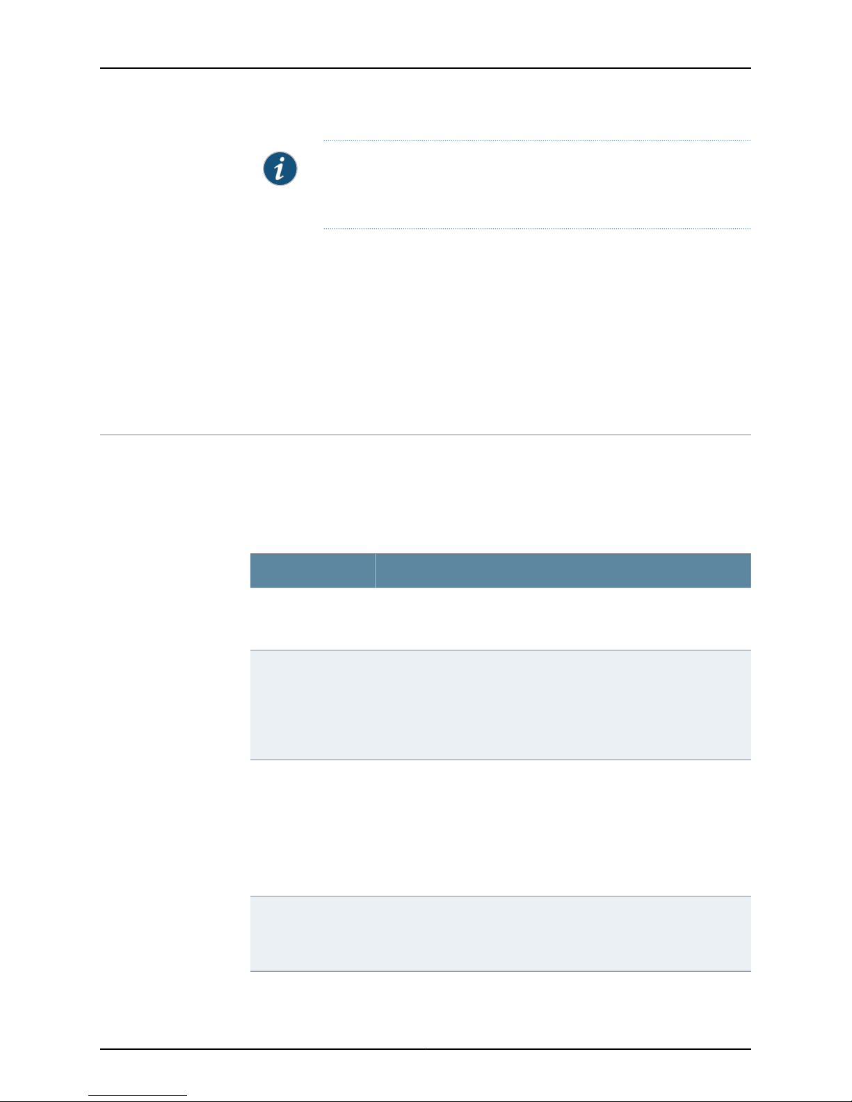
NOTE: Install the device only in restricted areas, such as dedicated
equipment rooms and equipment closets, in accordance with Articles
110-16, 110-17, and 110-18 of the National Electrical Code, ANSI/NFPA 70.
Related
Documentation
SRX240 Services Gateway Chassis on page 7•
• SRX240 Services Gateway Site Electrical Wiring Guidelines on page 143
• SRX240 Services Gateway Rack Requirements on page 33
• ClearanceRequirementsfor Airflow andHardware Maintenance onthe SRX240Services
Gateway on page 34
• Interface Cable and Wire Specificationsfor the SRX240 Services Gateway on page 149
SRX240 Services Gateway Rack Requirements
The SRX240 Services Gateway can be installed in a rack. Many types of racks are
acceptable, including front-mount racks and four-post (telco) racks.
Table 17 on page 33provides thedetails on rack size,clearance,and airflowrequirements.
Table 17: Rack Requirements for the Services Gateway
SpecificationsRack Requirements
Rack Size
A 19 in. (48.3 cm) rack as defined in Cabinets, Racks, Panels, and
Associated Equipment (document number EIA-310-D) published by the
Electronics Industry Association (http://www.eia.org).
Rack Requirements
Spacing of Mounting
Bracket and Flange
Holes
Connecting to the
Building Structure
•
The outer edges of the mounting brackets extend the width of either
chassis to 19 in. (48.3 cm).
•
The front of the chassis extends approximately0.5 in.(1.27 cm)beyond
the mounting ears.
•
Maximum permissible ambient temperature when two devices are
placed side by side in a 19 in. rack is 40οC.
•
The holes within each rack set are spaced at 1 U. The device can be
mounted in any rack that provides holes or hole patterns spaced at
1-U [1.75 in. (4.5 cm)] increments.
•
The mounting brackets and front-mount flanges used to attach the
chassis to a rack are designed to fasten to holes spaced at rack
distances of 1 U (1.75 in.).
•
The mounting holesin themounting bracketsprovided withthe device
are spaced 1.25 in. (3.2 cm) apart (top and bottom mounting hole).
Always secure the rack in which you are installing the services gateway
to the structure of the building. If your geographical area is subject to
earthquakes, bolt therack tothe floor.For maximum stability, also secure
the rack to ceiling brackets.
33Copyright © 2013, Juniper Networks, Inc.
Page 48
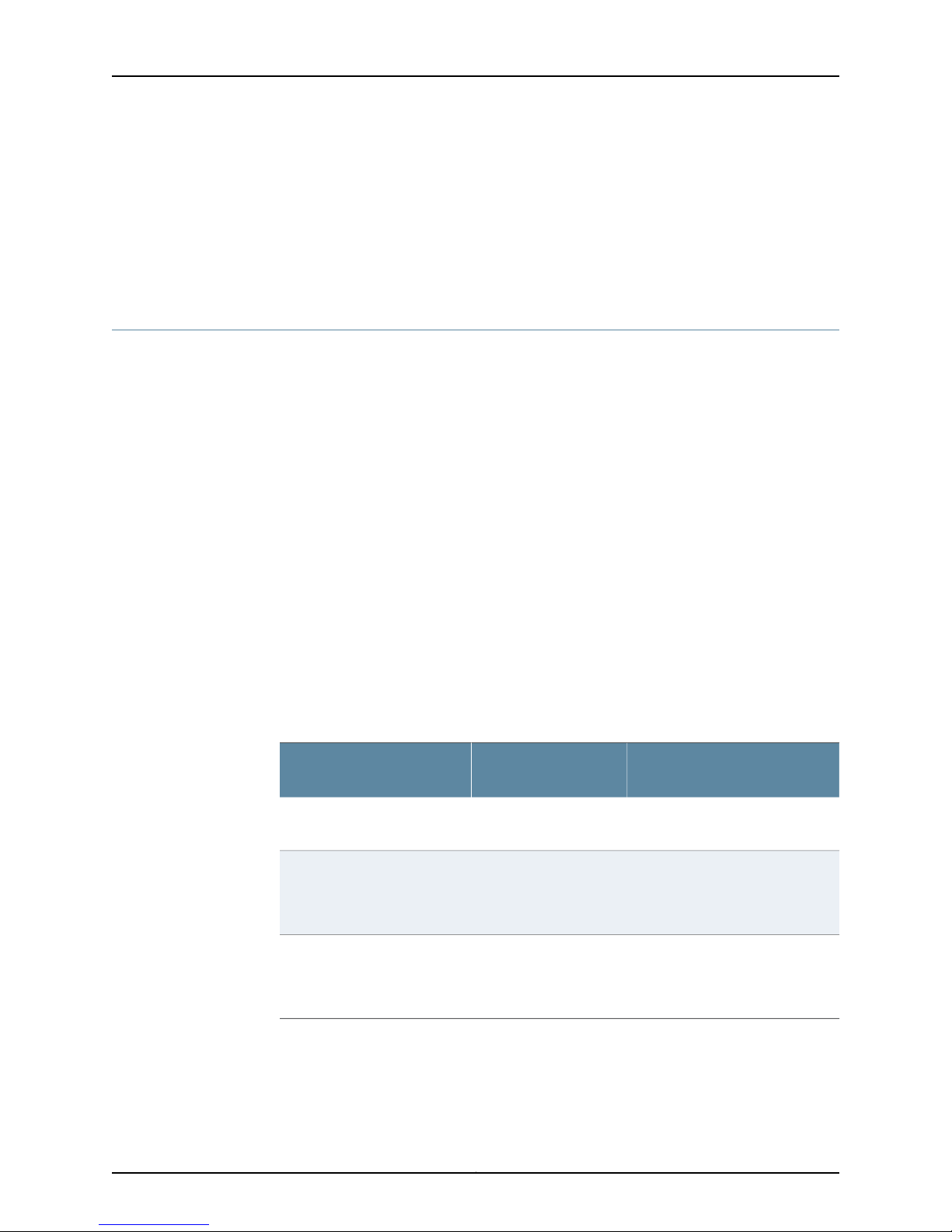
SRX240 Services Gateway Hardware Guide
Related
Documentation
General Site Guidelines for Installing the SRX240 Services Gateway on page 32•
• ClearanceRequirementsfor Airflow andHardware Maintenance onthe SRX240Services
Gateway on page 34
• SRX240 Services Gateway Electrical and Power Requirements on page 35
Clearance Requirements for Airflow and Hardware Maintenance on the SRX240
Services Gateway
When planning the installation site for the SRX240 Services Gateway, you need to allow
sufficient clearance around the rack.
When planning the installation site for the services gateway, consider the following:
•
For the cooling system to function properly, the airflow around the chassis must be
unrestricted.
•
For service personnel to remove and install hardware components, there must be
adequate space at the front and back of the device.
•
For theDC power supplymodel, ensurethat you follow theNEBS recommendation—The
NEBS GR-63 recommends that you allow at least 30 in. (72.6 cm) in front of the rack
and 24 in. (61.0 cm) behind the rack.
•
If you are mounting the device in a rack with other equipment, or if you are placing it
on the desktop near other equipment, ensure that the exhaust from other equipment
does not blow into the intake vents of the chassis.
Related
Documentation
Table 18 onpage 34 provides information onthe clearance requirements formaintaining
the optimum airflow and the distances for facilitating easy maintenance of the device.
Table 18: Clearance Requirements for the Services Gateway
Recommended
ClearanceLocation
2.5 in. (6.35 cm)Betweenfront-mounting flange
and rack or cabinet edge
2.5 in. (6.35 cm)Betweenside ofthe chassisand
any non-heat-producing
surface such as a wall or
cabinet side
2.5 in. (6.35 cm)Betweenside ofthe chassisand
devices that have fans or
blowers
General Site Guidelines for Installing the SRX240 Services Gateway on page 32•
• SRX240 Services Gateway Rack Requirements on page 33
Requirement for Clearance
Space for cable management and
organization
Space for the cooling system to
function properly and to maintain
unrestricted airflow around the
chassis
Space for the cooling system to
function properly and to maintain
unrestricted airflow around the
chassis
Copyright © 2013, Juniper Networks, Inc.34
Page 49

Chapter 5: Preparing the Site for the SRX240 Services Gateway Installation
• SRX240 Services Gateway Electrical and Power Requirements on page 35
SRX240 Services Gateway Electrical and Power Requirements
There are factors you must consider while planning the electrical wiring and power
availability at your site. These factors include the following requirements:
•
Power specifications and requirements for the device
•
Electrical wiring guidelines for the device installation site
•
Power, connection, and power cord specifications for the device
•
Grounding guidelines and specifications for the device
Related
Documentation
• General Site Guidelines for Installing the SRX240 Services Gateway on page 32
• SRX240 Services Gateway Rack Requirements on page 33
• ClearanceRequirementsfor Airflow andHardware Maintenance onthe SRX240Services
Gateway on page 34
35Copyright © 2013, Juniper Networks, Inc.
Page 50

SRX240 Services Gateway Hardware Guide
Copyright © 2013, Juniper Networks, Inc.36
Page 51
CHAPTER 6
Installation Overview for the SRX240
Services Gateway
This chapter includes the following topic:
•
Installation Overview for the SRX240 Services Gateway on page 37
Installation Overview for the SRX240 Services Gateway
After you have prepared your installation site, you are ready to unpack and install the
services gateway. It is important to proceed through the installation process as shown
in Table 19 on page 37.
Table 19: InstallationProcess Sequencefor the SRX240 Services Gateway
For More InformationProcessSteps
Review the safety guidelines.1
2
3
4
Verify that you have prepared your site
for the installation of the services
gateway using the checklist.
Unpack the services gateway andverify
that the parts are received.
Prepare the services gateway for
installation.
Install the services gateway.5
“SRX240 Services Gateway Safety
Requirements, Warnings, and
Guidelines” on page 43
“Site Preparation Checklist for the
SRX240 Services Gateway” on page 31
“Unpacking the SRX240 Services
Gateway” on page 41
“Preparing the SRX240 Services
Gateway for Installation” on page 43
“Installing the SRX240 Services
Gateway” on page 44
37Copyright © 2013, Juniper Networks, Inc.
Page 52
SRX240 Services Gateway Hardware Guide
Table 19: Installation Process Sequence for the SRX240 Services
Gateway (continued)
For More InformationProcessSteps
Related
Documentation
Connect the power supply6
“Connecting the SRX240 Services
Gateway to the AC Power Source” on
page 49
(For SRX240 Services Gatewaywith AC
power supply models)
“Connecting the SRX240 Services
Gateway DC Power Supply Model to a
DC Power Source” on page 50
(For SRX240 ServicesGateway withDC
power supply models)
Connect cables to external devices.7
“Connecting and Organizing Interface
Cables to the SRX240 Services
Gateway” on page 54
Connect the grounding cable.8
“Grounding the SRX240 Services
Gateway” on page 55
Power on the services gateway.9
“Powering On and Powering Off the
SRX240 Services Gateway” on page 57
• SRX240 Services Gateway Safety Requirements, Warnings, and Guidelineson page43
• General Site Guidelines for Installing the SRX240 Services Gateway on page 32
• Unpacking the SRX240 Services Gateway on page 41
• Preparing the SRX240 Services Gateway for Installation on page 43
• Connecting and Organizing Interface Cables to the SRX240 Services Gateway on
page 54
• Grounding the SRX240 Services Gateway on page 55
• Powering On and Powering Off the SRX240 Services Gateway on page 57
Copyright © 2013, Juniper Networks, Inc.38
Page 53

CHAPTER 7
Required Tools and Parts for Installing and
Maintaining the SRX240 Services
Gateway
This chapter includes the following topic:
•
Required Tools and Parts for Installing and Maintaining the SRX240 Services
Gateway on page 39
Required Tools and Parts for Installing and Maintaining the SRX240 Services Gateway
Table 20 on page 39 lists the tools and equipments required to install and maintain the
SRX240 Services Gateway.
Table 20: Required Tools and Parts for Installing and Maintaining the
SRX240 Services Gateway
Installing the SRX240
Services Gateway
Connecting the SRX240
Services Gateway
Connecting the SRX240
Services Gateway to a DC
power source
Grounding the SRX240
Services Gateway
•
Phillips (+) screwdrivers,
number–2 and number–3
•
Tie wrap
Electrostatic discharge (ESD)
grounding wrist strap
•
DC power source cables (12–14
AWG) with ring lug (Molex
190700067 or equivalent) (not
provided)
•
Phillips (+) screwdriver, number 1
Phillips (+) screwdrivers, numbers 1
and 2
Related TopicTools and PartsTask
“Installing the SRX240
Services Gateway” on
page 44
“Connecting the SRX240
Services Gateway to the AC
Power Source” on page 49
“Connecting the SRX240
ServicesGatewayDC Power
Supply Model to a DC
Power Source” on page 50
“Grounding the SRX240
Services Gateway” on
page 55
39Copyright © 2013, Juniper Networks, Inc.
Page 54
SRX240 Services Gateway Hardware Guide
Table 20: Required Tools and Parts for Installing and Maintaining the
SRX240 Services Gateway (continued)
Related TopicTools and PartsTask
Related
Documentation
Replacing the air filter on
the SRX240 Services
Gateway ( DC power
Electrostatic discharge (ESD)
grounding wrist strap
“Replacing the Air Filter on
the SRX240 Services
Gateway” on page 90
supply model)
Packing the SRX240
Services Gateway
•
Blank panels to cover empty slots
•
Electrostatic bag or antistatic mat,
for each component
•
Electrostatic discharge (ESD)
“Packing the SRX240
Services Gateway and
Components for Shipment”
on page 156
grounding wrist strap
• Unpacking the SRX240 Services Gateway on page 41
• Installing the SRX240 Services Gateway on page 44
• Grounding the SRX240 Services Gateway on page 55
• Connecting the SRX240 Services Gateway to the AC Power Source on page 49
• Packing the SRX240 Services Gateway and Components for Shipment on page 156
Copyright © 2013, Juniper Networks, Inc.40
Page 55

CHAPTER 8
Unpacking the SRX240 Services Gateway
This chapter includes the following topics:
•
Unpacking the SRX240 Services Gateway on page 41
•
Verifying Parts Received with the SRX240 Services Gateway on page 41
Unpacking the SRX240 Services Gateway
The SRX240 Services Gateway is shipped in a cardboard carton and secured with foam
packing material. The carton also contains an accessory box and the SRX240 Services
Gateway Quick Start.
NOTE: The servicesgatewayis maximallyprotectedinside the shipping crate.
Do not unpack it until you are ready to begin installation.
To unpack the services gateway:
1. Open the box in which the device is shipped.
2. Verify the parts received as in the list provided in Verifying Parts Received topic. See
Related Topics.
3. Store the shipping box and packing material in case you need to return or move the
device at a later time.
Related
Documentation
Required Tools and Parts for Installing and Maintaining the SRX240 Services Gateway
•
on page 39
• Verifying Parts Received with the SRX240 Services Gateway on page 41
• Preparing the SRX240 Services Gateway for Installation on page 43
Verifying Parts Received with the SRX240 Services Gateway
The SRX240 Services Gateway shipment package contains a packing list that includes
all parts and accessories available with the device. Check the parts in the shipment
against the items on the packing list. The packing list specifies the part numbers and
descriptions of each part in your order.
41Copyright © 2013, Juniper Networks, Inc.
Page 56
SRX240 Services Gateway Hardware Guide
A fully configured SRX240 Services Gateway contains the chassis with installed
components, listed in Table 21 on page 42 and an accessory box, which contains the
parts listed in Table 22 on page 42.
Table 21: Parts List for a Fully Configured SRX240 Services Gateway
NOTE: If any part is missing, contact your Juniper Networks customerservice
representative.
NOTE: The parts shipped with your device can vary depending on the
configuration you ordered.
QuantityComponent
1Rack Mounting Kit
Related
Documentation
13-prong power cord
[Not available for SRX240 Services Gateway with DC powersupply models]
1DB-9 to RJ-45 adapter, straight through, 7 feet
Table 22: Accessory Parts List for the SRX240 Services Gateway
QuantityPart
1Juniper Networks Product Warranty
1End User License Agreement
1SRX240 Services Gateway Quick Start.
1Security Products Safety Guide
1Juniper Networks Compliance Form Letter
1Product Registration
• Unpacking the SRX240 Services Gateway on page 41
• Preparing the SRX240 Services Gateway for Installation on page 43
• Installing the SRX240 Services Gateway on page 44
Copyright © 2013, Juniper Networks, Inc.42
Page 57
CHAPTER 9
Installing the SRX240 Services Gateway
This chapter includes the following topics:
•
SRX240 Services Gateway Safety Requirements, Warnings, and Guidelineson page 43
•
Preparing the SRX240 Services Gateway for Installation on page 43
•
Installing the SRX240 Services Gateway on page 44
•
Replacing or Installing Mini-Physical Interface Modules in the SRX240 Services
Gateway on page 47
SRX240 Services Gateway Safety Requirements, Warnings, and Guidelines
To avoid harm to yourself orthe deviceas you installand maintain it, follow the guidelines
for working with and near electrical equipment, as well as the safety procedures for
working with devices. For a discussion of how to make the installation site a safe
environment along with a list of safety warnings, see Appendix A, Safety and Regulatory
Compliance Information.
NOTE: Providing an exhaustive set of guidelines for working with electrical
equipment is beyond the scope of this guide.
Related
Documentation
Preparing the SRX240 Services Gateway for Installation on page 43•
• Installing the SRX240 Services Gateway on page 44
Preparing the SRX240 Services Gateway for Installation
You can mount an SRX240 Services Gateway in a rack. The services gateway can be
mounted on four-post (telco) racks, enclosed cabinets, and open-frame racks.
Table 23: SRX240 Services Gateway Preinstallation Checklist
Additional InformationTask
Verify that the installation site meets the
requirements.
“General Site Guidelines for Installing the SRX240
Services Gateway” on page 32
43Copyright © 2013, Juniper Networks, Inc.
Page 58
SRX240 Services Gateway Hardware Guide
Table 23: SRX240 Services Gateway PreinstallationChecklist (continued)
Additional InformationTask
Removethe services gateway chassis from
the shipping carton.
Verify the parts you have received.
Related
Documentation
General Site Guidelines for Installing the SRX240 Services Gateway on page 32•
• Unpacking the SRX240 Services Gateway on page 41
• Verifying Parts Received with the SRX240 Services Gateway on page 41
• Installing the SRX240 Services Gateway on page 44
Installing the SRX240 Services Gateway
You can front-mount or center-mount the SRX240 Services Gateway in a rack.
NOTE: If you are installing multipledevices in one rack, install the lowestone
first and proceed upward in the rack.
To install the device in a rack:
“Unpacking the SRX240 Services Gateway” on
page 41
“Verifying Parts Received with the SRX240 Services
Gateway” on page 41
Copyright © 2013, Juniper Networks, Inc.44
Page 59
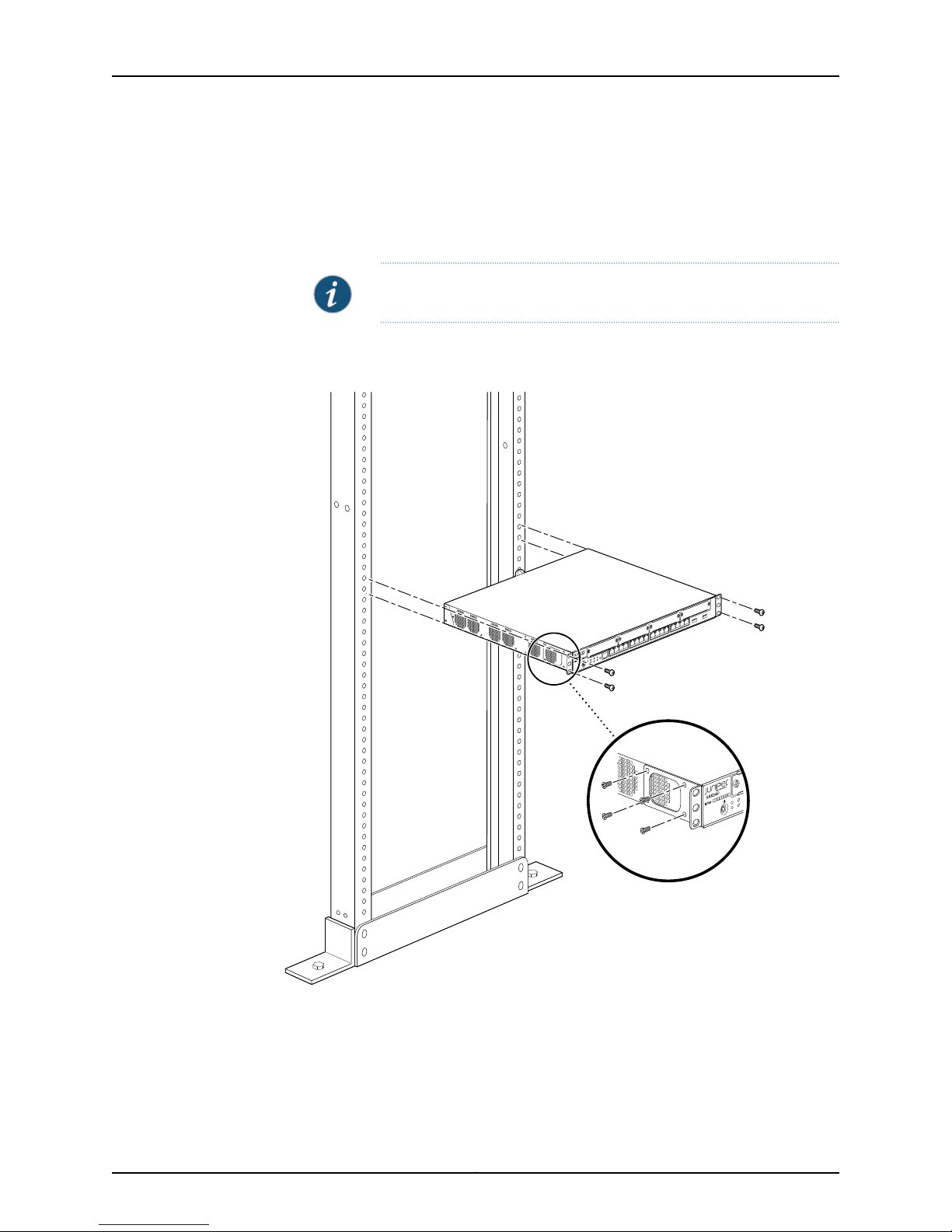
g030507
Chapter 9: Installing the SRX240 Services Gateway
1. Position a mounting bracket oneach side of the chassis. You can position the brackets
in:
•
Front-mount position as shown in Figure 10 on page 45.
•
Center-mount position as shown in Figure 11 on page 45.
NOTE: Positioning the brackets in the center offers greater stability.
Figure 10: Installing the SRX240 Services Gateway in a Rack (FrontMount)
Figure 11: Installing the SRX240 Services Gateway in a Rack (CenterMount)
45Copyright © 2013, Juniper Networks, Inc.
Page 60
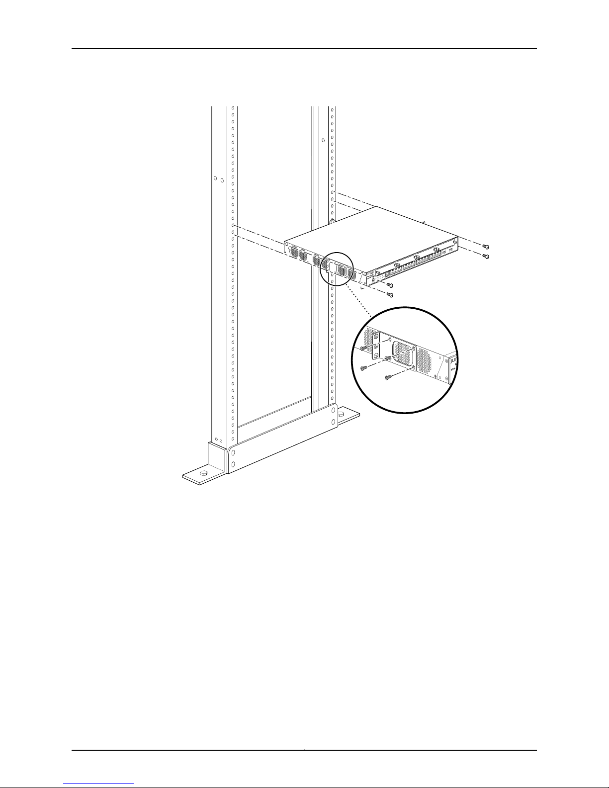
g037545
SRX240 Services Gateway Hardware Guide
2. Use a number–2 Phillips screwdriver to install the screws that secure the mounting
brackets to the chassis.
3. Have one person grasp the sides of the device, lift it, and position it in the rack.
4. Align the bottom hole in each mounting bracket with a hole in each rack rail, making
sure the chassis is level.
5. Have a second person install a mounting screw into each of the two aligned holes.
Use a number–3 Phillips screwdriver to tighten the screws.
6. Install the second screw in each mounting bracket.
7. Verify that the mounting screws on one side of the rack are aligned with the mounting
screws on the opposite side and that the device is level.
Related
Documentation
Preparing the SRX240 Services Gateway for Installation on page 43•
• Required Tools and Parts for Installing and Maintaining the SRX240 Services Gateway
on page 39
Copyright © 2013, Juniper Networks, Inc.46
Page 61
Chapter 9: Installing the SRX240 Services Gateway
• SRX240 Services Gateway Installation Safety Guidelines and Warnings on page 116
Replacingor Installing Mini-Physical InterfaceModules in the SRX240 Services Gateway
Mini-Physical Interface Modules (Mini-PIMs) are circuit boards that you can install in a
device for enhanced functionality based on your requirements. They enable you to easily
add or change physical interfaces on a device.
The Mini-Physical Interface Module (Mini-PIM) slot is covered with a blank faceplate to
maintain proper airflow through the services gateway. Before installing the Mini-PIM, you
must remove the faceplate.
See the SRX Series Services Gateways for the Branch Physical Interface Modules Hardware
Guide for information about installing the Mini-PIMs.
NOTE: The Mini-PIMs available on the SRX240 Services Gateway are not
hot-swappable.You needto power off the device beforeremoving or installing
Mini-PIMs.
Related
Documentation
• SRX240 Services Gateway Installation Safety Guidelines and Warnings on page 116
• Required Tools and Parts for Installing and Maintaining the SRX240 Services Gateway
on page 39
• Installing the SRX240 Services Gateway on page 44
47Copyright © 2013, Juniper Networks, Inc.
Page 62

SRX240 Services Gateway Hardware Guide
Copyright © 2013, Juniper Networks, Inc.48
Page 63

CHAPTER 10
g037506
Connecting, Grounding, and Powering On
the SRX240 Services Gateway
This chapter includes the following topics:
•
Connecting the SRX240 Services Gateway to the AC Power Source on page 49
•
Connecting the SRX240 Services Gateway DC Power Supply Model to a DC Power
Source on page 50
•
Connecting and Organizing Interface Cables to the SRX240 Services
Gateway on page 54
•
Grounding the SRX240 Services Gateway on page 55
•
Powering On and Powering Off the SRX240 Services Gateway on page 57
Connecting the SRX240 Services Gateway to the AC Power Source
Figure 12 on page 49 shows how the SRX240 Services Gateway is connected to an AC
power source.
Figure 12: SRX240 Services Gateway Power Supply Connection
49Copyright © 2013, Juniper Networks, Inc.
Page 64
SRX240 Services Gateway Hardware Guide
To connect the device to the power supply:
1. Attachan electrostatic discharge (ESD)grounding strap toyour barewrist, andconnect
the other end of the ESD strap to the ESD point on the rack.
2. Insert the appliance coupler end of a power cord into the appliance inlet on the power
supply faceplate.
3. Insert the plug into an AC power source receptacle.
NOTE: The services gateway must be connected to earth ground during
normal operation. The protectiveearthing terminal on the rear of the chassis
is provided to connect the services gateway to ground.
CAUTION: We recommend using a surge protectorfor the powerconnection.
NOTE: Use the cable tie holder to secure the power cord on to the power
supply point.
NOTE: We strongly recommend that you use only the 3-prong power cord
supplied with your services gateway. If you are using a 2-prong power cord,
then ensure that your services gateway is adequately grounded using the
grounding point available on the back panel of the chassis.
Related
Documentation
Installing the SRX240 Services Gateway on page 44•
• Required Tools and Parts for Installing and Maintaining the SRX240 Services Gateway
on page 39
• Connecting and Organizing Interface Cables to the SRX240 Services Gateway on
page 54
• Grounding the SRX240 Services Gateway on page 55
• Powering On and Powering Off the SRX240 Services Gateway on page 57
Connecting the SRX240 Services Gateway DC Power Supply Model to a DC Power
Source
WARNING: DC-powered SRX240 Services Gateways are intended for
installation only in a restricted access location.
Copyright © 2013, Juniper Networks, Inc.50
Page 65
Chapter 10: Connecting, Grounding, and Powering On the SRX240 Services Gateway
WARNING: Before performing the following procedure, ensure that power is
removedfrom the DC circuit. Toensure that all power is off, locate the circuit
breaker on the panel board that services the DC circuit, switch the circuit
breaker to the off position, and tape the switch handle of the circuit breaker
in the off position.
Required tools and parts:
•
DC power source cables (12–14 AWG) with ring lug (Molex 190700067 or equivalent)
(not provided)
•
Phillips (+) screwdriver, number 1
Before you begin:
•
Ensure that you have taken the necessary precautions to prevent ESD damage.
•
Ensure that you have connected the device chassis to earth ground.
CAUTION: Before you connect power to the services gateway, a licensed
electrician must attach a cable lug to the grounding and power cables that
you use. A cable with an incorrectly attached lug can damage the device (for
example, by causing a short circuit).
To meet safety and electromagnetic interference (EMI) requirements and
to ensure proper operation, you must connectthe SRX240 Services Gateway
to ground before you connect it to power.
You connect DC source power to the device by attaching power cables from the external
DC power sources to the terminal studs on the DC power feed faceplates.
To connect the DC source power to the device:
1. Ensure that the input circuit breaker is open so that the voltage across the DC power
source cable leads is 0 V and that the cable leads will not become active while you
are connecting DC power.
NOTE: The DC power feed in SRX240 Services Gateway DC power supply
model has four terminals labeled A+, B+, A–, and B– for connecting DC
power source cables labeled positive (+) and negative(–). The DC power
feed section on the SRX240 Services Gateway with DC power supply
model is shipped with jumpers from the A+ input to B+ input tied together
and links (jumpers) from the A– input to B– input tied together.
2. Remove the screw securing the terminal blockcover using the Phillips (+) screwdriver,
number 1 and remove the terminal block cover as shown in Figure 13 on page 52. Save
the screw.
51Copyright © 2013, Juniper Networks, Inc.
Page 66
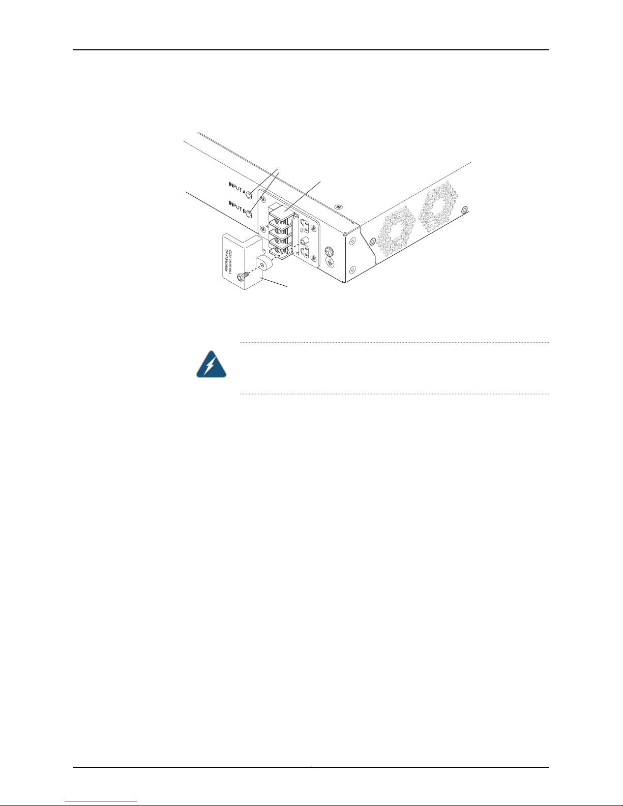
g037544
Terminal
block cover
Terminal block
LEDs
SRX240 Services Gateway Hardware Guide
Figure 13: DC Power Feed on SRX240 Services Gateway with DC Power
Supply Model
3. Remove the screws on the terminals using the Phillips (+) screwdriver,number 1. Save
the screws.
WARNING: Ensure thatthe power cables do not blockaccess to the device
or drape where people can trip on them.
4. Connect the power feed tothe power sources as shownin Figure14 onpage 53. Secure
power source cables tothe power feedon the device byscrewing thering lugs attached
to the cables to the appropriate terminals by using the screw from the terminals.
Copyright © 2013, Juniper Networks, Inc.52
Page 67
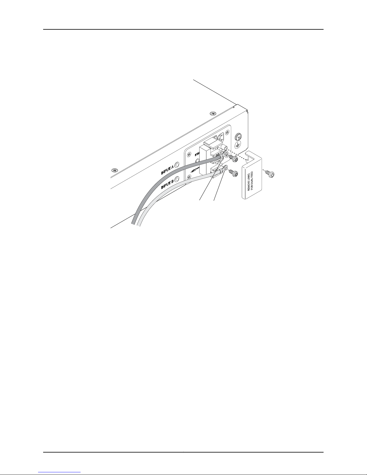
g037540
DC Ring lugs
Chapter 10: Connecting, Grounding, and Powering On the SRX240 Services Gateway
Figure 14: Connecting DC Power to the SRX240 Services Gateway with
DC Power Supply Model
To connect to a single power source:
1. Leave the links (jumpers) on the terminal blocks in place.
2. Secure the ring lug of the RETURN (+) DC power source cable to the A+ terminal
on the terminal block.
3. Secure the ring lug of the -48 VDC power source cable to the A– terminal on the
terminal block.
4. Tighten the screws on the power supply terminals until snug using the Phillips (+)
screwdriver, number–2. Do not overtighten—apply between 8 lb-in. (0.9 Nm) and
9 lb-in. (1.02 Nm) of torque to the screws.
To connect to two power sources:
1. Remove the links (jumpers) and insulator on the power supply terminal block.
2. Secure the ring lug of the RETURN (+) DC power source cable from the first DC
power source to the A+ terminal.
3. Secure the ring lug of the -48V DC power source cable from the first DC power
source to the A– terminal.
4. Secure the ring lug of the Return (+) DC power source cable from the second DC
power source to the B+ terminal.
53Copyright © 2013, Juniper Networks, Inc.
Page 68
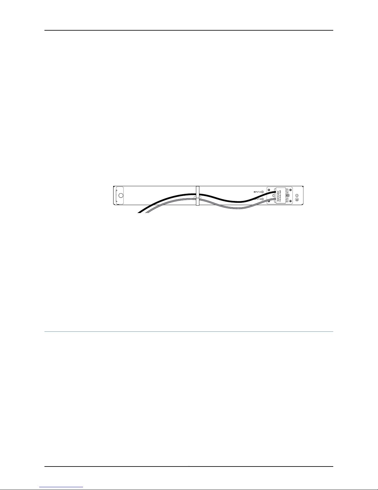
g037541
SRX240 Services Gateway Hardware Guide
5. Secure the ring lug of the -48VDC power source cable from the second DC power
source to the B– terminal.
6. Tighten thescrews onthe powersupply terminals usingthe Phillips (+) screwdriver,
number 1. Do not overtighten—apply between 8 lb-in. (0.9 Nm) and 9 lb-in. (1.02
Nm) of torque to the screws.
5. Replace the terminal block cover and secure it using the screw. Use the Phillips (+)
screwdriver, number 1 to tighten the screw.
6. Close the input circuit breaker.
7. Verifythat thepower cables donot block access torouter components ordrape where
people can trip on them. Use the cable tie holder as shown in Figure 15 on page 54 to
secure cables so that they are not supporting their own weight as they hang to the
floor
Figure 15: Organizing the Power Cables Using a Cable Tie Holder
8. Verify that the LEDs on the power supply are lit green and are on steadily.
Related
Documentation
SRX240 Services Gateway Power Supply on page 20•
• SRX240 Services Gateway DC Power Specifications and Requirements on page 146
• SRX240 Services Gateway LEDs on page 14
• Required Tools and Parts for Installing and Maintaining the SRX240 Services Gateway
on page 39
• Grounding the SRX240 Services Gateway on page 55
• Powering On and Powering Off the SRX240 Services Gateway on page 57
Connecting and Organizing Interface Cables to the SRX240 Services Gateway
You connect the interfaces installed in the services gateway to various network media.
Each type of interface on a services gateway uses a particular medium to transmit data.
You must configure each network interface before it can operate on the device.
To connect the interface cable to the device:
1. Have ready a length of the type of cable used by the interface.
2. Insert the cable connector into the cable connector port on the interface faceplate.
3. Arrange network cables as follows to prevent them from dislodging or developing
stress points:
•
Secure cables so that they are not supporting their own weight as they hang to the
floor.
Copyright © 2013, Juniper Networks, Inc.54
Page 69
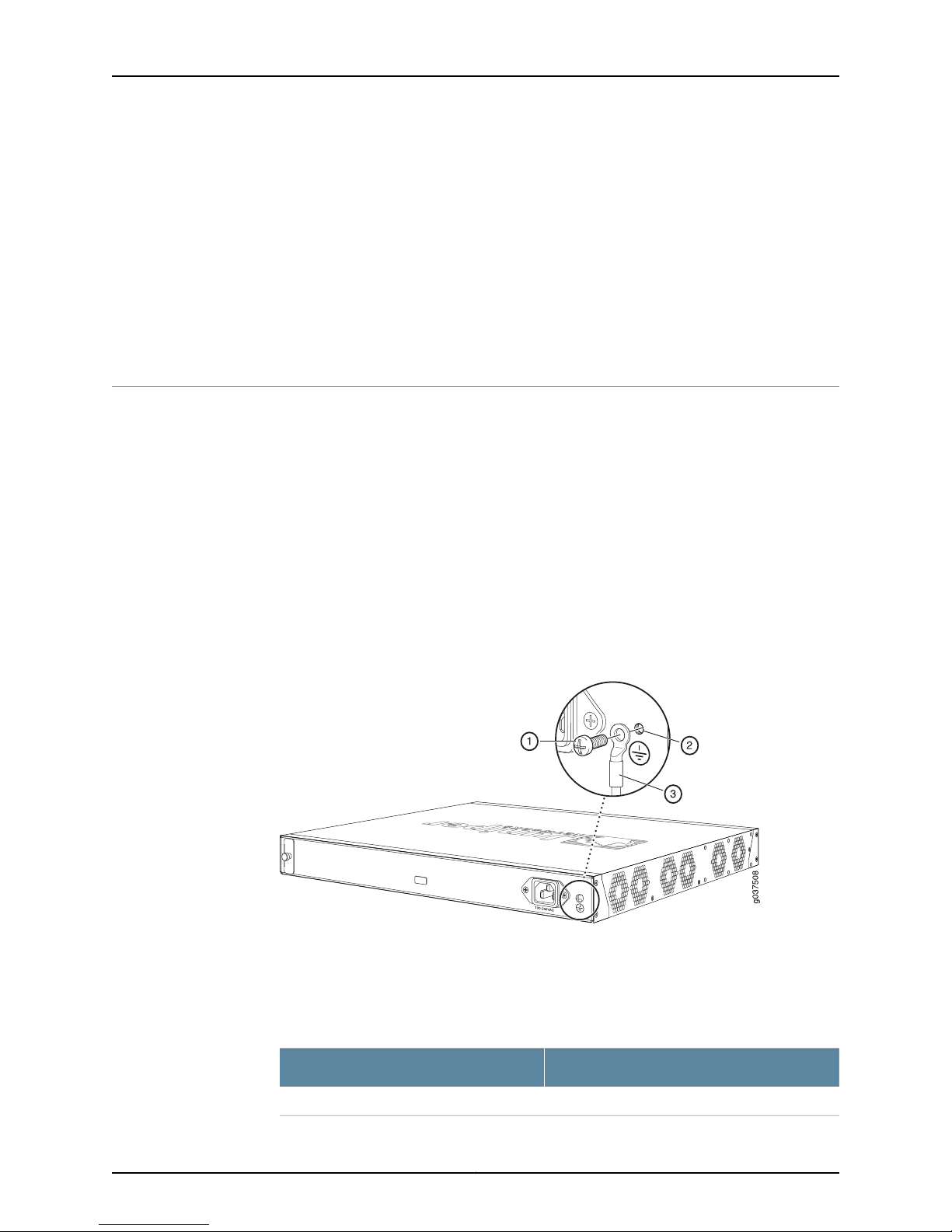
Chapter 10: Connecting, Grounding, and Powering On the SRX240 Services Gateway
•
Place excess cable out of the way in neatly coiled loops.
•
Use fasteners to maintain the shape of cable loops.
Related
Documentation
Installing the SRX240 Services Gateway on page 44•
• Grounding the SRX240 Services Gateway on page 55
• Connecting the SRX240 Services Gateway to the AC Power Source on page 49
• Powering On and Powering Off the SRX240 Services Gateway on page 57
Grounding the SRX240 Services Gateway
The following tools and parts are required for grounding the SRX240 Services Gateway:
•
Grounding cable for your services gateway—The grounding cable must be minimum
14 AWG (2 mm²), minimum 90°C wire, or as permitted by the local code.
•
Grounding lug—Ring-type, vinyl-insulatedTV14-6R lug orequivalentfor your grounding
cable
•
Washers and10-32x.25-in. screwsto secure thegrounding lugto theprotectiveearthing
terminal
•
Phillips (+) screwdrivers, numbers 1 and 2
Figure 16 on page 55 shows the SRX240 grounding point.
Figure 16: Grounding the SRX240 Services Gateway
You groundthe device byconnecting agrounding cable toearth ground and then attaching
it to the chassis grounding points using one M3 screw.
Table 24 on page 55 lists the specifications of the grounding cable used with the device.
Table 24: Grounding Cable Specifications for the Services Gateway
SpecificationGrounding Requirement
14 AWG single-strand wire cableGrounding cable
55Copyright © 2013, Juniper Networks, Inc.
Page 70
SRX240 Services Gateway Hardware Guide
Table 24: Grounding Cable Specifications for the Services
Gateway (continued)
SpecificationGrounding Requirement
Up to 4 AAmperage of grounding cable
Grounding lug
Ring-type, vinyl-insulated TV14-6R lug or
equivalent
CAUTION: Before device installation begins, a licensed electrician must
attach a cable lug to the grounding and power cables that you use. A cable
with an incorrectly attached lug can damage the device (for example, by
causing a short circuit).
To ground the device:
1. Connect the grounding cable to a proper earth ground.
2. Verify that a licensed electrician has attached the cable lug to the grounding cable.
3. Place the grounding cable lug over the grounding point onthe upper rear of the chassis.
4. Secure the grounding cable lug to the grounding point with the screw. Apply between
6 in.-lb (0.67 Nm) and 8 in.-lb (0.9 Nm) of torque to the screws.
5. Dress the grounding cable and verify that it does not touch or block access to the
services gateway components and that it does not cause create a tripping hazard.
NOTE: The deviceshould be permanently connectedto groundduring normal
operation.
Related
Documentation
Installing the SRX240 Services Gateway on page 44•
• Required Tools and Parts for Installing and Maintaining the SRX240 Services Gateway
on page 39
• Connecting and Organizing Interface Cables to the SRX240 Services Gateway on
page 54
• Connecting the SRX240 Services Gateway to the AC Power Source on page 49
• Powering On and Powering Off the SRX240 Services Gateway on page 57
Copyright © 2013, Juniper Networks, Inc.56
Page 71
Chapter 10: Connecting, Grounding, and Powering On the SRX240 Services Gateway
Powering On and Powering Off the SRX240 Services Gateway
This topic includes the following sections:
•
Powering On the SRX240 Services Gateway on page 57
•
Powering Off the SRX240 Services Gateway on page 57
•
Resetting the SRX240 Services Gateway on page 59
Powering On the SRX240 Services Gateway
To power on the services gateway:
1. Ensure that you have connected the power supply to the services gateway.
2. Insert the plug into an AC power source receptacle (for SRX240 Services Gateway
with AC power supply, and PoE).
Or
Attach the power cable to the DC power source (for SRX240 Services Gateway with
DC power supply model). Ensure that the DC power source is connected according
to the guidelines recommended in “Connecting the SRX240 Services Gateway DC
Power Supply Model to a DC Power Source” on page 50.
3. The services gateway starts up as the power supply completes its startup sequence.
The Power LED glows during startup and remains on steadily when the services
gateway is operating normally.
NOTE: After the power supply is turned on, it can take up to 60 seconds for
status indicators—such as the Status and Power LEDs on the front panel of
chassis to show that the power supply is functioning normally.
NOTE: We recommend that you issue the CLI command request system
power-off when you wantto power off the device immediately afterthe device
is powered on.
Powering Off the SRX240 Services Gateway
You can power off the services gateway in one of the following ways:
•
Graceful shutdown—Press and immediately release the Power button. The device
begins gracefully shutting down the operating system and then powers itself off.
WARNING: Use the graceful shutdown method to power off or reboot the
services gateway.
57Copyright © 2013, Juniper Networks, Inc.
Page 72
SRX240 Services Gateway Hardware Guide
•
Forced shutdown—Press the Power button and hold it for 10 seconds. The device
immediately powers itself off without shutting down the operating system.
WARNING: Use the forced shutdown method as a last resort to recover
the services gateway if the services gateway operating system is not
responding to the graceful shutdown method.
WARNING: Do not press the Power button while the services gateway is
shutting down.
CAUTION: Forced shutdown can result in data loss and corruption of the file
system.
NOTE: To remove power completely from the services gateway, unplug the
AC power cord (for SRX240 Services Gateway with AC power supply, and
PoE models) or switch off the DC power source (SRX240 Services Gateway
with DC power supply).
After powering off a power supply, wait at least 10 seconds before turning it
back on. After powering on a power supply, wait at least 10 seconds before
turning it off.
The Power button on the services gateway is a standby power switch.
If you press the Power button to power off the services gateway when it is
still connected to a power source, 12 V (for SRX240 Services Gateway with
AC and DC Power Supply models) / 52 V (SRX240 Services Gateway PoE
models) powerwill still be available in the chassis and the devicewill be fully
powered off.
TIP: When you are powering off the servicesgateway, the followingmessage
is displayed:
Turning the system power off.
You can now safely remove the power cable to completely disconnect the
power from the device.
NOTE: You can use the request systemreboot command to schedule a reboot
of the services gateway.
Copyright © 2013, Juniper Networks, Inc.58
Page 73
Chapter 10: Connecting, Grounding, and Powering On the SRX240 Services Gateway
For more information abouthalting, powering off,or rebooting theservices gatewayusing
the CLI, see the following guides:
•
Initial Configuration for Security Devices
•
Monitoring and Troubleshooting for Security Devices
Resetting the SRX240 Services Gateway
The RESET CONFIG button located at the front panel of the SRX240 Services Gateway
removes the current configuration and resets the device to the default configuration. The
button is recessed in the front panel to prevent it from being pressed accidentally.
NOTE: Pressing and holding the RESET CONFIG button for 15 seconds or
more deletes all configurations on the device and loads and commits the
factory configuration.
Related
Documentation
• Required Tools and Parts for Installing and Maintaining the SRX240 Services Gateway
on page 39
• Connecting and Organizing Interface Cables to the SRX240 Services Gateway on
page 54
• Connecting the SRX240 Services Gateway to the AC Power Source on page 49
• Connecting the SRX240 Services Gateway DC Power Supply Model to a DC Power
Source on page 50
59Copyright © 2013, Juniper Networks, Inc.
Page 74

SRX240 Services Gateway Hardware Guide
Copyright © 2013, Juniper Networks, Inc.60
Page 75

CHAPTER 11
SRX240 Services Gateway
Autoinstallation
This chapter includes the following topic:
•
SRX240 Services Gateway Autoinstallation Overview on page 61
SRX240 Services Gateway Autoinstallation Overview
The autoinstallation process begins any time a services gateway is powered on and
cannot locate a valid configuration file in the internal flash. Typically, a configuration file
is unavailable when a services gateway is powered on for the first time or if the
configuration file is deleted from the internal flash. The autoinstallation feature enables
you to deploy multiple services gateways from a central location in the network.
If you are setting up many devices, autoinstallation can help automate the configuration
process by loading configuration files onto new or existing devices automatically over
the network. You can use either the J-Web interface or the CLI to configure a device for
autoinstallation.
Related
Documentation
For the autoinstallation process to work, you must store one or more host-specific or
default configuration files on a configuration server in the network and have a service
available—typically Dynamic Host Configuration Protocol (DHCP)—to assignan IPaddress
to the services gateway.
Autoinstallation takes place automatically when you connect an Ethernet port on a new
services gateway to the network and power on the device. To simplify the process, you
can explicitly enable autoinstallation on a device and specify a configuration server, an
autoinstallation interface, and a protocol for IP address acquisition.
For more information about configuring autoinstallation, see the following topics:
•
Initial Configuration for Security Devices
•
Monitoring and Troubleshooting for Security Devices
• Connecting the SRX240 Services Gateway to the AC Power Source on page 49
• Grounding the SRX240 Services Gateway on page 55
• Powering On and Powering Off the SRX240 Services Gateway on page 57
61Copyright © 2013, Juniper Networks, Inc.
Page 76

SRX240 Services Gateway Hardware Guide
Copyright © 2013, Juniper Networks, Inc.62
Page 77

CHAPTER 12
Connecting the SRX240 Services Gateway
to Management Devices
This chapter includes the following topics:
•
Connecting to the SRX240 Services Gateway Setup Wizard on page 63
•
Connecting the SRX240 Services Gateway to the CLI on page 64
•
Connecting the Modem at the SRX240 Services Gateway End on page 67
•
Connecting the Modem to the Console Port on the SRX240 Services
Gateway on page 68
•
Connecting to the CLI at the User End for the SRX240 Services Gateway on page 69
Connecting to the SRX240 Services Gateway Setup Wizard
If you plan to use the setup wizard to configure the services gateway, you must connect
through one of the built-in Gigabit Ethernet ports. You can use any built-in Ethernet port
except port 0/0.
To enable communication between the management device and the services gateway,
ports 0/1 through 0/15 are preconfigured with the IP address 192.168.1.1. DHCP is used to
assign an IP address on the 192.168.1.0/24 network to any connected device.
To connect to the Ethernet port:
1. Ensure that the IP address for the Ethernet port on the management device is
configured in one of the following ways:
•
The IP address is assigned by DHCP.
•
The IP address is on the 192.168.1.0/24 subnetwork (but is not 192.168.1.1).
2. Turn off the management device.
3. Plug oneend ofthe CAT-5e (Ethernet cable) into the Ethernet port on the management
device.
4. Connect the other end of the Ethernet cable to the built-in Gigabit Ethernet port (any
one port between 0/1 and 0/15) on the services gateway as shown in
Figure 17 on page 64.
63Copyright © 2013, Juniper Networks, Inc.
Page 78
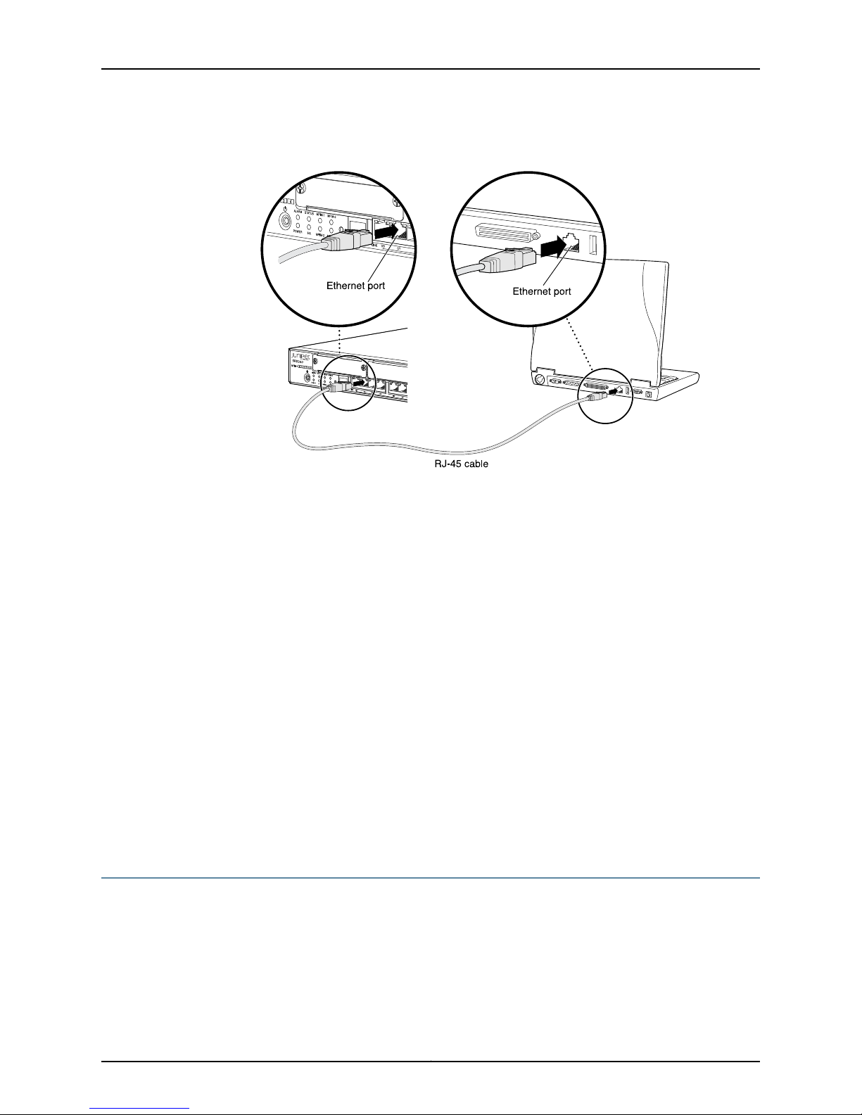
g037511
SRX240 Services Gateway Hardware Guide
Figure 17: Connecting to the Ethernet Porton an SRX240 Services Gateway
If the services gateway has not already been powered on, power it on now.
5. Wait until the Status LED on the front panel of the services gateway turns steadily
green.
6. Turn on the power to the management device. The services gateway assigns an IP
address to the management device within the 192.168.1.0/24 subnetwork if the
management device is configured to use DHCP.
7. To access the setup wizard, open a Web browser on the management device and
enter the IP address 192.168.1.1 in the address field.
Related
Documentation
Performing Initial Software Configuration on the SRX240 Services Gateway Using the
•
Setup Wizard on page 75
• Connecting the SRX240 Services Gateway to the CLI on page 64
• Connecting to the CLI at the User End for the SRX240 Services Gateway on page 69
• Connecting the Modem at the SRX240 Services Gateway End on page 67
• Connecting the Modem to the Console Port on the SRX240 Services Gateway on
page 68
Connecting the SRX240 Services Gateway to the CLI
This topic includes the following sections:
•
Connecting the Services Gateway to the CLI Locally on page 65
•
Connecting a Services Gateway to the CLI Remotely on page 66
Copyright © 2013, Juniper Networks, Inc.64
Page 79
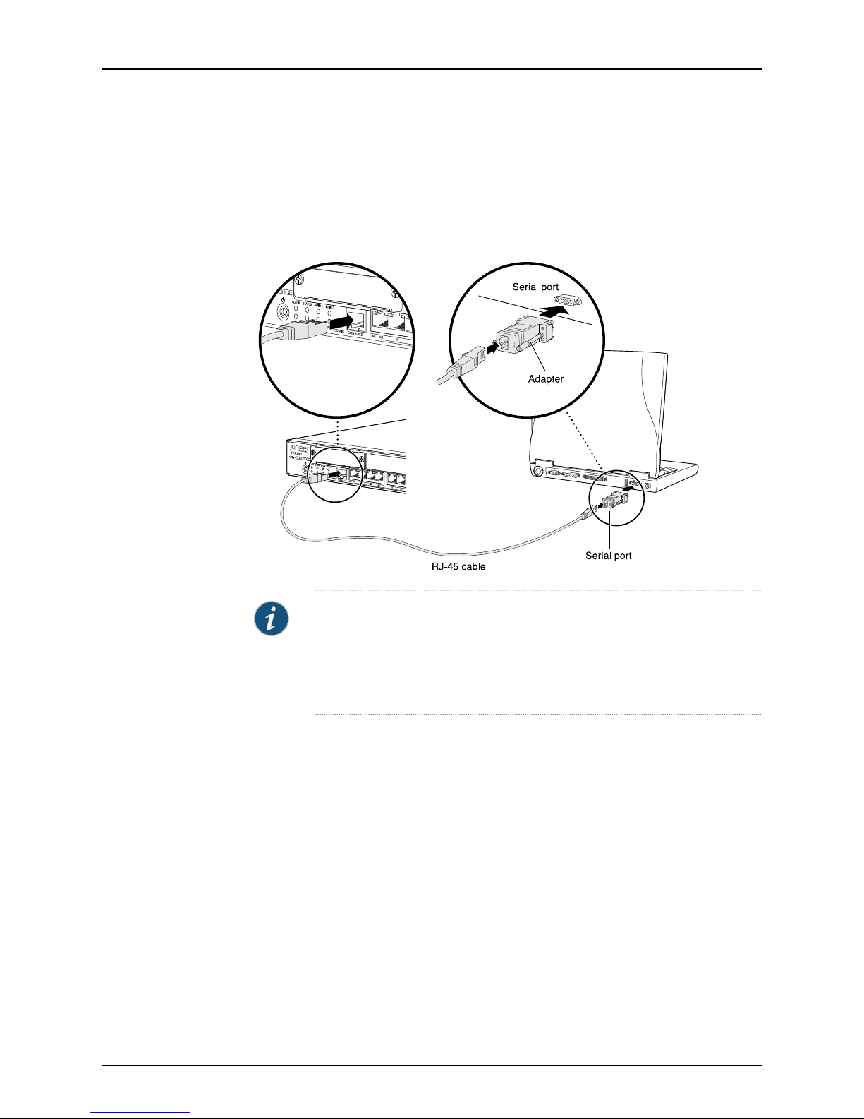
g037512
Chapter 12: Connecting the SRX240 Services Gateway to Management Devices
Connecting the Services Gateway to the CLI Locally
If you plan to use the CLI to configure the SRX240 Services Gateway, you must connect
the services gateway through the console port as shown in Figure 18 on page 65.
Figure 18: Connecting an SRX240 Services Gateway to the CLI
NOTE: Figure 18 on page 65 shows a connection to a local management
device. A remote connection to the services gateway through a modem
requires the cable and connector shown (provided in the services gateway
accessorybox), plus a DB-9 male to DB-25 male (or similar) adapter for your
modem, which you must purchase separately.
To connect to the CLI using a local management device through the console port on the
services gateway:
1. Turn off power to the services gateway.
2. Turn off power to the management device, such as a PC or laptop computer, that you
are using to access the CLI.
3. Plug one end of the CAT-5e (Ethernet cable) supplied with your services gateway
into the RJ-45 to DB-9 serial port adapter supplied with your services gateway.
4. Plug the RJ-45 to DB-9 serial port adapter into the serial port on the management
device.
5. Connect the other end of the Ethernet cable to the console port on the services
gateway.
6. Turn on the power to the management device.
65Copyright © 2013, Juniper Networks, Inc.
Page 80
SRX240 Services Gateway Hardware Guide
7. Start your asynchronous terminal emulation application (such as Microsoft Windows
HyperTerminal) and select the appropriate COM port to use (for example, COM1).
8. Configure the port settings shown in Table 25 on page 66.
Table 25: Port Settings When Connecting the Services Gateway to the
CLI Locally
ValuePort Settings
9600Bits per second
8Data bits
NoneParity
1Stop bits
NoneFlow control
9. Power onthe services gateway by pressing the Power button on thefront panel. Verify
that the Power LED on the front panel turns green.
The terminal emulation screen on your management device displays the startup
sequence. When the services gateway has finished starting up, a login prompt appears.
10. Log in as the user root. No password is required at initial connection, but you must
assign a root password before committing any configuration settings.
Connecting a Services Gateway to the CLI Remotely
You can connect the services gateway to the CLI from a remote location through two
dial-up modems:
•
A modem that is connected to the console port on the services gateway
•
A second modem connected to a remote management device
The modem connection allows you to remotely perform the same console operations
you can perform locally.
Related
Documentation
Connecting to the SRX240 Services Gateway Setup Wizard on page 63•
• Connecting to the CLI at the User End for the SRX240 Services Gateway on page 69
• Connecting the Modem at the SRX240 Services Gateway End on page 67
• Connecting the Modem to the Console Port on the SRX240 Services Gateway on
page 68
Copyright © 2013, Juniper Networks, Inc.66
Page 81

Chapter 12: Connecting the SRX240 Services Gateway to Management Devices
Connecting the Modem at the SRX240 Services Gateway End
Before you can connect a dial-up modem to the console port on the SRX240 Services
Gateway, you must configure the modem to accept a call on the first ring and accept
DTR signals. You must also disable flow control on the modem.
NOTE: These instructions use Hayes-compatible modem commands to
configure the modem. If your modem is not Hayes-compatible, refer to the
documentationfor yourmodem and enterthe equivalentmodem commands.
To configure the modem on the services gateway end:
1. Connect the modem to a PC or laptop computer.
2. Power on the modem.
3. From the PC or laptop computer, start your asynchronous terminal emulation
application (such as Microsoft Windows HyperTerminal), and select the COM port to
which the modem is connected (for example, COM1).
4. Configure the port settings as shown in Table 26 on page 67.
Table 26: Port Settings for Configuring the Modem on the Services
Gateway End
ValuePort Setting
9600Bits per second
8Data bits
NoneParity
1Stop bits
NoneFlow control
5. In the HyperTerminal window, enter AT.
For more information on the AT commands, see the following topics:
•
Initial Configuration for Security Devices
•
Monitoring and Troubleshooting for Security Devices
An OKresponse verifies thatthe modem can communicate successfully with the COM
port on the PC or laptop.
6. Configure the modem to answer a call on the first ring by entering ATS0=1.
7. Configure the modem to accept modem control DTR signals by entering AT&D1.
67Copyright © 2013, Juniper Networks, Inc.
Page 82

SRX240 Services Gateway Hardware Guide
8. Disable flow control by entering AT&K0.
9. Save modem settings by entering AT&W.
Related
Documentation
Connecting to the SRX240 Services Gateway Setup Wizard on page 63•
• Connecting the SRX240 Services Gateway to the CLI on page 64
• Connecting to the CLI at the User End for the SRX240 Services Gateway on page 69
• Connecting the Modem to the Console Port on the SRX240 Services Gateway on
page 68
Connecting the Modem to the Console Port on the SRX240 Services Gateway
To connect the dial-up modem to the console port on the services gateway:
1. Turn off power to the services gateway.
2. Turn off power to the modem.
3. Plug one end of the Ethernet cable supplied with your services gateway into the
console port.
4. Plug the other end of the CAT-5e (Ethernet cable) into the RJ-45 to DB-9 serial port
adapter supplied with your services gateway.
5. Connect the serial port adapter to a separately purchased DB-9 female to DB-25
male adapter or other adapter appropriate for your modem.
6. Plug the modem adapter into the DB-25 connector on the modem.
Related
Documentation
7. Connect the modem to your telephone network.
8. Turn on the power to the modem.
9. Power onthe services gateway by pressing the Power button on thefront panel. Verify
that the Power LED on the front panel turns green.
NOTE: Most modems have an RS-232 DB-25 connector. You must
separately purchase an adapter to connect your modem to the RJ-45 to
DB-9 adapter and Ethernet cable supplied with the services gateway.
Connecting to the SRX240 Services Gateway Setup Wizard on page 63•
• Connecting the SRX240 Services Gateway to the CLI on page 64
• Connecting the Modem at the SRX240 Services Gateway End on page 67
• Connecting to the CLI at the User End for the SRX240 Services Gateway on page 69
Copyright © 2013, Juniper Networks, Inc.68
Page 83
Chapter 12: Connecting the SRX240 Services Gateway to Management Devices
Connecting to the CLI at the User End for the SRX240 Services Gateway
To remotely connect to the CLI through a dial-up modem connected to the console port
on the services gateway:
1. Connect a modem at your remote location to a management device such as a PC or
laptop computer.
2. Start your asynchronous terminal emulation application (such as Microsoft Windows
HyperTerminal) on the PC or laptop computer.
3. Select the COM port to which the modem is connected (for example, COM1).
4. Configure the port settings shown in Table 27 on page 69.
Table 27: Port Settings for Connecting to the CLI at User End
ValuePort Setting
9600Bits per second
8Data bits
NoneParity
1Stop bits
NoneFlow control
5. In the HyperTerminal window, enter AT.
For more information on the AT commands, see the following topics:
•
Initial Configuration for Security Devices
•
Monitoring and Troubleshooting for Security Devices
An OKresponse verifies thatthe modem can communicate successfully with the COM
port on the PC or laptop.
6. Dial the modem that is connected to the console port on the services gateway by
entering ATDT remote-modem-number. For example, if the number of the modem
connectedto theconsole port on the services gatewayis 0013033033030,enter ATDT
0013033033030.
The services gateway login prompt appears.
7. Log in as the user root. No password is required at initial connection, but you must
assign a root password before committing any configuration settings.
Related
Documentation
• Connecting to the SRX240 Services Gateway Setup Wizard on page 63
• Connecting the SRX240 Services Gateway to the CLI on page 64
• Connecting the Modem at the SRX240 Services Gateway End on page 67
69Copyright © 2013, Juniper Networks, Inc.
Page 84

SRX240 Services Gateway Hardware Guide
• Connecting the Modem to the Console Port on the SRX240 Services Gateway on
page 68
Copyright © 2013, Juniper Networks, Inc.70
Page 85

CHAPTER 13
Performing Initial Software Configuration
on the SRX240 Services Gateway
This chapter includes the following topics:
•
SRX240 Services Gateway Software Configuration Overview on page 71
•
Performing Initial Software Configuration on the SRX240 Services Gateway Using the
Setup Wizard on page 75
•
Performing Initial Software Configuration on the SRX240 Services Gateway Using the
CLI on page 78
•
Performing Initial Software Configuration on the SRX240 Services Gateway Using the
J-Web Interface on page 80
•
SRX240 Services Gateway Secure Web Access Overview on page 85
SRX240 Services Gateway Software Configuration Overview
This topic includes the following sections:
•
Preparing the SRX240 Services Gateway for Configuration on page 71
•
Understanding the Factory Default Configuration on page 72
•
Understanding Built-In Ethernet Ports and Initial Configuration on page 72
•
Mapping the Chassis Cluster Ports on page 73
•
Understanding Management Access on page 74
Preparing the SRX240 Services Gateway for Configuration
The services gateway is shipped withthe Juniper Networks Junos operating system (Junos
OS) preinstalled. When the services gateway is powered on, it is ready to be configured.
You can perform the initial configuration of the services gateway by using the
browser-based setup wizard or by using the command-line interface (CLI).
Before configuring the services gateway, gather the configuration information required
to deploy the services gateway in your network. At minimum, the setup wizard requires
the following information:
•
Device name to be used on the network
71Copyright © 2013, Juniper Networks, Inc.
Page 86

SRX240 Services Gateway Hardware Guide
•
Password for the root user
•
Time information for the services gateway location:
•
Local time zone
•
Name or IP address of a Network Time Protocol (NTP) server, if NTP is used to set
the time on the services gateway
•
Local date and time if an NTP server is not used to set the time
Understanding the Factory Default Configuration
Your services gatewaycomes configured witha default configuration. This factory default
configuration sets up the following network topology:
•
Interface ge-0/0/0 (port 0/0) is configured for Internet access. A DHCP client running
on the interface enables the interface to receive its network settings—IP address,
default gateway, and DNS servers—from an Internet service provider (ISP).
•
Interfaces ge-0/0/1 through ge-0/0/15 (port 0/1 through port 0/15) are configured as
switched interfaces in a VLAN on which the IP address 192.168.1.1/24 is configured.
•
A DHCP server is active on interfaces ge-0/0/1 through ge-0/0/15. The DHCP server
assigns IP addresses in the 192.168.1.0/24 network to connected devices.
The default configuration also includes the following security configuration:
•
Two security zones are created: trust and untrust.
•
Interfacege-0/0/0 is in the untrust zone, while interfaces ge-0/0/1 through ge-0/0/15
are in the trust zone.
•
A security policy is created that permits outbound traffic from the trust zone to the
untrust zone. Inbound traffic originating in the untrust zone is blocked.
•
Source Network Address Translation (NAT) is configured on the trust zone.
Understanding Built-In Ethernet Ports and Initial Configuration
During the initial configuration of the services gateway, how you use the built-in Ethernet
ports (ports 0/0 through 0/15) depends on the initial configuration you are performing:
•
Configuration using autoinstallation—Use the built-in Ethernet port 0/0 to connect to
the DHCP server. A DHCP client is configured on this interface, allowing the services
gateway to receive its IP address from the DHCP server.
•
Configuration using the setup wizard—Use the following built-in Ethernet ports:
•
Port 0/1—Connect your management device to this port. A DHCP server running on
this interface automatically assigns your management device an IP address on the
same subnetwork as the interface, allowing your management device to
communicate with the services gateway through this interface.
Copyright © 2013, Juniper Networks, Inc.72
Page 87
Chapter 13: Performing Initial Software Configuration on the SRX240 Services Gateway
•
Port 0/0—Connect your services gateway to the Internet on this port if you plan to
download purchased software licenses through the setup wizard. A DHCP client
running on this interface allows it to receive its network settings from the ISP.
NOTE: Downloading of purchased licenses from the setup wizard is
available only in Junos OS Release 11.2R3 or later.
•
Configuration of a chassis cluster—Perform the initial configuration of the chassis
cluster using a console connection. Before youperform theinitial configuration, connect
the built-in Ethernet ports as follows:
•
Port 0/0—Connect to the out-of-band management network for management of
the services gateway. When you enable chassis clustering as part of configuring the
chassis cluster, the management interface (fxp0) is automatically created on this
port.
•
Port 0/1—Connect to the other device in the chassis cluster. When you enablechassis
clustering, the control interface between the two devices (fxp1) is automatically
created on this port.
You must also make another connection between the two devices for the fabric link.
You canuse any available Gigabit Ethernet port for this connection. You must configure
the interface you choose as thefabric link. For more information on configuring chassis
clusters, see the Security Basics.
Mapping the Chassis Cluster Ports
A chassis cluster is created by physically connecting two identical SRX240 Services
Gateways together usinga pairof the same type of Ethernetconnections. The connection
is made for both a control link and a fabric (data) link between the two services gateway.
The fxp0 port is dedicated as the out-of-band management interface for each of the
services gateway in the chassis cluster setup and the fxp1 port is dedicated as the
chassis-cluster control port.
On theSRX240 Services Gateway, the fxp1 port is not user configurable whenthe services
gateway is operating in chassis cluster mode.
Table 28 on page 73 shows the mapping of the chassis cluster ports.
Table 28: Mapping the Chassis Cluster Ports on an SRX240 Services
Gateway
Management InterfaceEthernet Ports on SRX240 Services Gateway
fxp0 (management port)0/0 (ge-0/0/0)
fxp1 (control port)0/1 (ge-0/0/1)
73Copyright © 2013, Juniper Networks, Inc.
Page 88

SRX240 Services Gateway Hardware Guide
NOTE: On SRX240 Services Gateway, the fabric link connection can be any
pair of Gigabit Ethernet interfaces.
Junos OS automatically creates the fxp0 and fxp1 interfaces on these ports when the
SRX240 Services Gateway is operating in chassis cluster mode.
For more information, see the following guides:
•
Security Basics
•
Interfaces for Security Devices
Understanding Management Access
Telnet allows you to connect to the services gateway and access the CLI to execute
commands from a remote system. Telnet CLIconnections are not encrypted and therefore
can be intercepted.
NOTE: Telnet accessto the root user is prohibited.Youmust use more secure
methods, such as SSH, to log in as root.
SSH provides the following features:
•
Allowsyou to connectto theservices gatewayand access the CLI to execute commands
from a remote system
•
Encrypts traffic so that it cannot be intercepted (unlike Telnet)
•
Can be configured so that connections are authenticated by a digital certificate
•
Uses public–private key technology for both connection and authentication
The SSH client software must be installed on the machine where the client application
runs. If the SSH private key is encrypted (for greater security), the SSH client must be
able to access the passphrase used to decrypt the key.
For information about obtaining SSH software, see http://www.ssh.com and
http://www.openssh.com.
If you are using a Junos XML protocol server to configure and monitor devices, you can
activate cleartext access on the device to allow unencrypted text to be sent directly over
a Transmission Line Protocol (TCP) connection without using any additional protocol
(such as SSH, SSL, or Telnet). For more information about the Junos XML management
protocol, see the Junos XML Management Protocol Guide.
NOTE: Information sent in cleartext is not encrypted and therefore can be
intercepted.
Copyright © 2013, Juniper Networks, Inc.74
Page 89

Chapter 13: Performing Initial Software Configuration on the SRX240 Services Gateway
If the device is operating in a Common Criteria environment, see the Configuration Guides
for Junos OS Public Sector Certifications.
Related
Documentation
Connecting to the SRX240 Services Gateway Setup Wizard on page 63•
• Connecting the SRX240 Services Gateway to the CLI on page 64
• Performing Initial Software Configuration on the SRX240 Services Gateway Using the
CLI on page 78
• Performing Initial Software Configuration on the SRX240 Services Gateway Using the
Setup Wizard on page 75
• SRX240 Services Gateway Secure Web Access Overview on page 85
Performing Initial Software Configuration on the SRX240 Services Gateway Using the
Setup Wizard
This topic describes how to perform the initial software configuration of your services
gateway using the setup wizard available in Junos OS Release 11.2R3 or later. If your
services gatewayis running anearlier version of Junos OS, see “PerformingInitial Software
Configuration on the SRX240 Services Gateway Using the J-Web Interface” on page 80.
This topic includes the following sections:
•
About the Setup Wizard on page 75
•
About the Default Setup Mode on page 76
•
About the Guided Setup Mode on page 76
•
Running the Setup Wizard on page 77
About the Setup Wizard
The setup wizard guides you step-by-step through configuring a services gateway that
can securely pass traffic. To help guide you through the process, the wizard:
•
•
•
•
You choose one of two paths through the wizard by selecting the configuration mode:
•
•
Provides recommended settings based on your previous selections. For example, the
wizard recommends security policies based on the security topology you have defined.
Determines which configuration tasks to present to you based on your selections. If a
configuration task is unnecessary given your selections, the wizard skips it.
Flags any missing required configuration when you attempt to leave a page.
Indicates which configuration elements or tasks are unavailable to you based on your
previous selections by graying them out.
Default Setup mode—This mode allows you to quickly set up a services gateway in a
default security configuration.
Guided Setup mode—This mode allows you to set up a services gateway in a custom
security configuration.
75Copyright © 2013, Juniper Networks, Inc.
Page 90

SRX240 Services Gateway Hardware Guide
About the Default Setup Mode
If you choose the Default Setup mode, the wizard takes you through the minimal
configurationneeded to set up the services gateway to securely pass trafficin the default
configuration. The resulting configuration is similar to the factory default configuration
described in “SRX240 Services Gateway Software Configuration Overview” on page 71,
except that the untrust and trust zones are renamed Internet and Internal zones.
In the Default Setup mode, you configure:
•
The device name
•
The password for the root account
•
Time information for services the gateway location:
•
Local time zone
•
Name or IP address of a Network Time Protocol (NTP) server, if NTP is used to set
the time on the services gateway
•
Local date and time if an NTP server is not used to set the time
The wizard also gives you the option ofusing the free 30-day trial licenses or downloading
purchased licenses. You cannot do additional configuration in the Default Setup
mode—you must commit your changes and exit the wizard to perform any additional
configuration. You can perform additional configuration by rerunning the wizard in the
Guided Setup mode, by using the J-Web interface, or by using the CLI.
See “SRX240 Services Gateway Software Configuration Overview” on page 71 for
step-by-stepinstructions on how to configure your services gatewayin the Default Setup
mode.
About the Guided Setup Mode
If you choose the Guided Setup mode, the wizard guides you through configuring your
services gateway in a custom security configuration. Configuration you can perform with
the setup wizard includes:
•
Specifying a static IP address, default gateway, and DNS servers for the Internet
interface
•
Creating user accounts and specifying roles for the accounts
•
Defining security zones and specifying which interfaces are in each zone
•
Enabling a DHCP server in a zone
•
Specifying what services—such as HTTP or SCP—are available in a zone
•
Creating VLANs
•
Defining security policies and Network Address Translation (NAT) rules
•
Creating a virtual private network (VPN) for remote users
Copyright © 2013, Juniper Networks, Inc.76
Page 91

Running the Setup Wizard
To run the setup wizard:
Chapter 13: Performing Initial Software Configuration on the SRX240 Services Gateway
NOTE: In the GuidedSetup mode, makesure youhave configuredthe Ethernet
interface you will be using for management access before you commit the
configuration.If you do not do so, you can lose access to the J-Web interface.
If you lose access to the J-Web interface, you can:
•
Make a console connection to the services gateway and configure access
using the CLI.
•
Resetthe servicesgatewayto its factory defaultconfigurationasdescribed
in “Loading the Rescue Configuration on the SRX240 Services Gateway”
on page105. This allowsyou to regain accessto the setup wizard and restart
the initial configuration.
Related
Documentation
1. Connect a laptop or desktop computer to any of the ports 0/1 through 0/15 as
described in“Connecting to the SRX240 ServicesGatewaySetup Wizard” on page 63.
2. If you will be using the setup wizard to download purchased licenses, connect your
services gateway to the Internet on port 0/0.
3. Open a Web browser on your laptop or desktop.
NOTE: Supported browsers are Windows Internet Explorer versions 7, 8,
and 9 and Mozilla Firefoxversions 4 and5. The minimum screen resolution
is 800 by 600 pixels.
4. Enter one of the following URLs: http://192.168.1.1 or https://192.168.1.1
When the Welcome page for the setup wizard appears, choose the setup mode you
want to use to configure the services gateway.
After you finish configuring the services gateway with the setup wizard and commit your
configuration,you are redirected to the J-Web interface.Thereafter, whenever you connect
to the services gateway, you are placed in the J-Web interface. You can access the setup
wizard from the J-Web interface and use it to reconfigure your services gateway. To do
so, select Configuration > Tasks > Run Setup Wizard.
Connecting to the SRX240 Services Gateway Setup Wizard on page 63•
• SRX240 Services Gateway Software Configuration Overview on page 71
• Performing Initial Software Configuration on the SRX240 Services Gateway Using the
CLI on page 78
• SRX240 Services Gateway Secure Web Access Overview on page 85
77Copyright © 2013, Juniper Networks, Inc.
Page 92

SRX240 Services Gateway Hardware Guide
Performing Initial Software Configuration on the SRX240 Services Gateway Using the
CLI
This procedure connects the services gateway to the network but does not enable it to
forwardtraffic. For complete information about enabling the services gateway to forward
traffic, including examples, see the appropriate Junos OS configuration guides.
To configure the software:
1. Verify that the services gateway is powered on.
2. Log in as the root user. There is no password.
3. Start the CLI:
root# cli
root@>
4. Enter configuration mode:
configure
[edit]
root@#
5. Set the root authentication password by entering a cleartext password, an encrypted
password, or an SSH public key string (DSA or RSA):
[edit]
root@# set system root-authentication plain-text-password
New password: password
Retype new password: password
6. Configure an administrator account on the services gateway:
[edit]
root@# set system login user admin class super-user authentication
plain-text-password
7. Commit the configuration to activate it on the services gateway:
[edit]
root@# commit
8. Log in as the administrative user you configured in Step 6.
9. Configure the name of the services gateway. If the name includes spaces, enclose the
name in quotation marks (“ ”) :
configure
[edit]
admin@# set system host-name host-name
10. Configure the traffic interface:
[edit]
admin@# set interfaces ge-0/0/1 unit 0 family inet address address/prefix-length
Copyright © 2013, Juniper Networks, Inc.78
Page 93

Chapter 13: Performing Initial Software Configuration on the SRX240 Services Gateway
11. Configure the default route:
[edit]
admin@# set routing-options static route 0.0.0.0/0 next-hop gateway
12. Configure basic security zones and bind them to traffic interfaces:
[edit]
admin@# set security zones security-zone untrust interfaces ge-0/0/1
13. Configure basic security policies:
[edit]
admin@# set security policies from-zone trust to-zone untrust policy policy-name
match source-address any destination-address any application any
admin@# set security policies from-zone trust to-zone untrust policy policy-name
then permit
14. Create a NAT rule for source translation of all Internet-bound traffic:
[edit]
admin@# set security nat source rule-set interface-nat from zone trust
admin@# set security nat source rule-set interface-nat to zone untrust
admin@# set security nat source rule-set interface-nat rulerule1 match source-address
0.0.0.0/0 destination-address 0.0.0.0/0
admin@# set security nat source rule-set interface-nat rule rule1 then source-nat
interface
15. Check the configuration for validity:
[edit]
admin@# commit check
configuration check succeeds
16. Commit the configuration to activate it on the services gateway:
[edit]
admin@# commit
commit complete
17. Optionally, display the configuration to verify that it is correct:
[edit]
user@host# show
system {
host-name devicea;
domain-name lab.device.net;
domain-search [ lab.device.net device.net ];
backup-device 192.168.2.44;
time-zone America/Los_Angeles;
root-authentication {
ssh-rsa "ssh-rsa [email protected]";
}
name-server {
10.148.2.32;
}
services {
}
ntp {
server 10.148.2.21;
}
79Copyright © 2013, Juniper Networks, Inc.
Page 94

SRX240 Services Gateway Hardware Guide
}
interfaces {
ge-0/0/0 {
}
lo0 {
}
}
18. Commit the configuration to activate it on the services gateway:
[edit]
admin@# commit
unit 0 {
family inet {
address 192.168.1.1/24;
}
}
unit 0 {
family inet {
address 172.16.1.24/32;
}
}
19. Optionally, configure additional properties by adding the necessary configuration
statements. Then commit the changes to activate them on the services gateway:
[edit]
admin@host# commit
20. When you have finished configuring the services gateway, exit configuration mode:
[edit]
admin@host# exit
admin@host>
Related
Documentation
Connecting the SRX240 Services Gateway to the CLI on page 64•
• Performing Initial Software Configuration on the SRX240 Services Gateway Using the
Setup Wizard on page 75
• SRX240 Services Gateway Software Configuration Overview on page 71
• SRX240 Services Gateway Secure Web Access Overview on page 85
Performing Initial Software Configuration on the SRX240 Services Gateway Using the
J-Web Interface
This topic describes how to perform the initial configuration of your services gateway
using the J-Web setup wizard that is available in Junos OS Release 11.2R2 or earlier. If
your services gateway is running Release 11.2R3 or later, see “Performing Initial Software
Configuration on the SRX240 Services Gateway Using the Setup Wizard” on page 75.
This topic includes the following sections:
•
Establishing Basic Connectivity on page 81
•
Configuring Basic System Properties on page 82
Copyright © 2013, Juniper Networks, Inc.80
Page 95
Establishing Basic Connectivity
To establish basic connectivity:
1. Connect an Ethernet cable fromany of the ports 0/1 through 0/15 to the Ethernet port
on the management device (workstation or laptop).
2. Connect the power cable to the device and a power source. (We recommend using
a surge protector.) Note the following indications:
•
Power LED (steadily green): The device is receiving power.
•
Status LED (steadily green): The device is operating normally.
3. Ensure that the management device acquires an IP address on the 192.168.1.0/24
subnetwork (other than 192.168.1.1) from the device.
Chapter 13: Performing Initial Software Configuration on the SRX240 Services Gateway
NOTE: The services gateway functions as a DHCP server and will assign
an IP address to the management device.
NOTE: If an IP address is not assigned to the management device,
manually configure an IP address in the 192.168.1.0/24 subnetwork. Do
not assign the 192.168.1.1 IP address to the management device, as this IP
address is assigned to the services gateway.
4. Access the J-Web interface:
a. Launch a Web browser from the management device.
NOTE: To access the J-Web interface, your management device
requiresa supported browser:either Microsoft InternetExplorer version
7.0 (or later) or Mozilla Firefox version 3.0 (or later).
b. Enter 192.168.1.1 in the Address box.
c. Specify the default user name as root. Do not enter any value in the Password box.
d. Press Enter. The J-Web Setup Wizard page opens.
5. Use the wizard to configure the basic settings, suchas Hostname, Domain Name, and
Root Password, for your services gateway.
The upperleft area of thewizard page shows where you are in the setup process. Click
a field in the wizard page to display information about that field in the lower left area
of the page.
81Copyright © 2013, Juniper Networks, Inc.
Page 96
SRX240 Services Gateway Hardware Guide
You can also use the wizard to configure the following settings:
•
Default gateway
•
DNS servers
•
Domain search
•
VLANs
•
Interfaces
6. Click Commit on the Review & Commit page to apply the configuration.
NOTE: All network and management access settings are optional.
See Table 29 on page 82 and Table 30 on page 83 summarize the
configuration details for the initial setup.
NOTE: After you configure the basic settings, the J-Web Setup wizard
redirects you to the J-Web pages where you can continue working in the
J-Web interface.
Configuring Basic System Properties
Table 29 on page 82 and Table 30 on page 83 summarize the configuration details for
initial setup.
Table 29: Required Setup Fields
Introduction
Configure System: Identification
Your ActionFieldSetup Wizard Page
Read the introduction page for
basic instructions on using the
setup wizard. Click Start to
continue.
Copyright © 2013, Juniper Networks, Inc.82
Page 97
Chapter 13: Performing Initial Software Configuration on the SRX240 Services Gateway
Table 29: Required Setup Fields (continued)
Your ActionFieldSetup Wizard Page
Host Name
Domain Name
Root Password (required)
(required)
Configure J-Web Preferences
J-Web starting page options
J-Web commit options
Table 30: Optional Setup Fields
Type the name of the services
gateway.
Type the name of the network
or subnetwork to which the
services gateway belongs.
Type the password that user
root will use to log in to the
device.
Retype the root password.Verify Root Password
Specify the tab you want to
appear when J-Web starts.
Specify when you want J-Web
to commit your configuration
changes.
Your ActionFunctionField
Configure System:
Identification
Interface Groups (VLANs)
Default Gateway
DNS Name Servers
Domain Search
Type the IP address of the
default gateway.
Type the IP address of each
server that maintains
databases for resolving
hostnames and IP addresses
and click Add.
Type the IP address or domain
name of each domain that
includes the services gateway
to include it in a DNS search
Use buttons to add, edit, or
delete VLANs
83Copyright © 2013, Juniper Networks, Inc.
Page 98
SRX240 Services Gateway Hardware Guide
Table 30: Optional Setup Fields (continued)
Your ActionFunctionField
Configure Interfaces
Configure System: Time
Current System Time
Time Zone
NTP Servers
Use buttons to add, edit, or
delete interfaces other than
VLANs.
NOTE: Make sure that you
have selected the required
services and protocols under
Services (Inbound) and
Protocols(Inbound). Select all
to permit all protocols and
services.
Use Reset Manually button to
reset the time.
Choose thetime zone from the
list
Add Network Time Protocol
(NTP) servers thatthe gateway
can reach to synchronize the
system time.
After you configure basic setup, the Setup wizard is no longer available, unless you reset
the device to the factory default and reboot it. To make changes to the configuration,
use the J-Web interface or the command-line interface (CLI).
Related
Documentation
You can use other wizards to configure basic firewall policies, VPN settings, and NAT
rules. Choose Configure > Wizards to use the available wizards. Use the J-Web interface
or the CLI for more extensive configuration.
For moreinstructions onmanaging users and operations, monitoring network performance,
upgrading software, anddiagnosing common problems on an SRX240 Services Gateway,
see the following guides:
•
Initial Configuration for Security Devices
•
Monitoring and Troubleshooting for Security Devices
Connecting to the SRX240 Services Gateway Setup Wizard on page 63•
• SRX240 Services Gateway Software Configuration Overview on page 71
• Performing Initial Software Configuration on the SRX240 Services Gateway Using the
CLI on page 78
• SRX240 Services Gateway Secure Web Access Overview on page 85
Copyright © 2013, Juniper Networks, Inc.84
Page 99

Chapter 13: Performing Initial Software Configuration on the SRX240 Services Gateway
SRX240 Services Gateway Secure Web Access Overview
You can manage a services gateway remotely through the J-Web interface. To
communicate with the services gateway, the J-Web interface uses Hypertext Transfer
Protocol (HTTP). HTTP allows easy Web access but no encryption. The data that is
transmitted between the Web browser and the services gateway by means of HTTP is
vulnerableto interception and attack.To enable secure Web access,the services gateway
supports HTTP over Secure Sockets Layer (HTTPS). You can enable HTTP or HTTPS
access on specific interfaces and ports as needed.
The services gateway uses the SSL protocol to provide secure management of services
gateways through the J-Web. SSL uses public-private key technology that requires a
paired private key and an authentication certificate for providing the SSL service. SSL
encrypts communication between your device and the Web browser with a session key
negotiated by the SSL server certificate.
An SSL certificate includes identifying information such as a public key and a signature
made by a certificate authority (CA). When you access the services gateway through
HTTPS, an SSL handshake authenticates the server and the client and begins a secure
session. If the information does not match or if the certificate has expired, your access
to the services gateway through HTTPS is restricted.
Related
Documentation
Without SSL encryption, communication between yourservices gateway and the browser
is sentin the open and can be intercepted.We recommend that youenable HTTPS access
on your WAN interfaces.
For more information about configuring secure Web access, see the following topics:
•
Initial Configuration for Security Devices
•
Monitoring and Troubleshooting for Security Devices
• SRX240 Services Gateway Software Configuration Overview on page 71
• Performing Initial Software Configuration on the SRX240 Services Gateway Using the
CLI on page 78
• Performing Initial Software Configuration on the SRX240 Services Gateway Using the
Setup Wizard on page 75
85Copyright © 2013, Juniper Networks, Inc.
Page 100

SRX240 Services Gateway Hardware Guide
Copyright © 2013, Juniper Networks, Inc.86
 Loading...