

Page 1

SRX 210 Services Gateway
Hardware Guide
Juniper Networks, Inc.
1194 North Mathilda Avenue
Sunnyvale, California 94089
USA
408-745-2000
www.juniper.net
Part Number: 530-025856-01, Revision 01
Page 2

This product includes the Envoy SNMP Engine, developed by Epilogue Technology, an Integrated Systems Company. Copyright © 1986-1997, Epilogue
Technology Corporation. All rights reserved. This program and its documentation were developed at private expense, and no part of them is in the public
domain.
This product includes memory allocation software developed by Mark Moraes, copyright © 1988, 1989, 1993, University of Toronto.
This product includes FreeBSD software developed by the University of California, Berkeley, and its contributors. All of the documentation and software
included in the 4.4BSD and 4.4BSD-Lite Releases is copyrighted by the Regents of the University of California. Copyright © 1979, 1980, 1983, 1986, 1988,
1989, 1991, 1992, 1993, 1994. The Regents of the University of California. All rights reserved.
GateD software copyright © 1995, the Regents of the University. All rights reserved. Gate Daemon was originated and developed through release 3.0 by
Cornell University and its collaborators. Gated is based on Kirton ’s EGP, UC Berkeley ’s routing daemon (routed), and DCN ’s HELLO routing protocol.
Development of Gated has been supported in part by the National Science Foundation. Portions of the GateD software copyright © 1988, Regents of the
University of California. All rights reserved. Portions of the GateD software copyright © 1991, D. L. S. Associates.
This product includes software developed by Maker Communications, Inc., copyright © 1996, 1997, Maker Communications, Inc.
Juniper Networks, the Juniper Networks logo, JUNOS, NetScreen, ScreenOS, and Steel-Belted Radius are registered trademarks of Juniper Networks, Inc. in
the United States and other countries. JUNOSe is a trademark of Juniper Networks, Inc. All other trademarks, service marks, registered trademarks, or
registered service marks are the property of their respective owners.
Juniper Networks assumes no responsibility for any inaccuracies in this document. Juniper Networks reserves the right to change, modify, transfer, or
otherwise revise this publication without notice.
Products made or sold by Juniper Networks or components thereof might be covered by one or more of the following patents that are owned by or licensed
to Juniper Networks: U.S. Patent Nos. 5,473,599, 5,905,725, 5,909,440, 6,192,051, 6,333,650, 6,359,479, 6,406,312, 6,429,706, 6,459,579, 6,493,347,
6,538,518, 6,538,899, 6,552,918, 6,567,902, 6,578,186, and 6,590,785.
SRX 210 Services Gateway Hardware Guide
Copyright © 2009, Juniper Networks, Inc.
All rights reserved. Printed in USA.
Revision History
February 2009 — Revision 01
The information in this document is current as of the date listed in the revision history.
SOFTWARE LICENSE
The terms and conditions for using this software are described in the software license contained in the acknowledgment to your purchase order or, to the
extent applicable, to any reseller agreement or end-user purchase agreement executed between you and Juniper Networks. By using this software, you
indicate that you understand and agree to be bound by those terms and conditions.
Generally speaking, the software license restricts the manner in which you are permitted to use the software and may contain prohibitions against certain
uses. The software license may state conditions under which the license is automatically terminated. You should consult the license for further details.
For complete product documentation, please see the Juniper Networks Web site at www.juniper.net/techpubs.
ii
Page 3

END USER LICENSE AGREEMENT
READ THIS END USER LICENSE AGREEMENT (“AGREEMENT”) BEFORE DOWNLOADING, INSTALLING, OR USING THE SOFTWARE. BY DOWNLOADING,
INSTALLING, OR USING THE SOFTWARE OR OTHERWISE EXPRESSING YOUR AGREEMENT TO THE TERMS CONTAINED HEREIN, YOU (AS CUSTOMER
OR IF YOU ARE NOT THE CUSTOMER, AS A REPRESENTATIVE/AGENT AUTHORIZED TO BIND THE CUSTOMER) CONSENT TO BE BOUND BY THIS
AGREEMENT. IF YOU DO NOT OR CANNOT AGREE TO THE TERMS CONTAINED HEREIN, THEN (A) DO NOT DOWNLOAD, INSTALL, OR USE THE SOFTWARE,
AND (B) YOU MAY CONTACT JUNIPER NETWORKS REGARDING LICENSE TERMS.
1. The Parties. The parties to this Agreement are (i) Juniper Networks, Inc. (if the Customer’s principal office is located in the Americas) or Juniper Networks
(Cayman) Limited (if the Customer’s principal office is located outside the Americas) (such applicable entity being referred to herein as “Juniper”), and (ii)
the person or organization that originally purchased from Juniper or an authorized Juniper reseller the applicable license(s) for use of the Software (“Customer”)
(collectively, the “Parties”).
2. The Software. In this Agreement, “Software” means the program modules and features of the Juniper or Juniper-supplied software, for which Customer
has paid the applicable license or support fees to Juniper or an authorized Juniper reseller, or which was embedded by Juniper in equipment which Customer
purchased from Juniper or an authorized Juniper reseller. “Software” also includes updates, upgrades and new releases of such software. “Embedded
Software” means Software which Juniper has embedded in or loaded onto the Juniper equipment and any updates, upgrades, additions or replacements
which are subsequently embedded in or loaded onto the equipment.
3. License Grant. Subject to payment of the applicable fees and the limitations and restrictions set forth herein, Juniper grants to Customer a non-exclusive
and non-transferable license, without right to sublicense, to use the Software, in executable form only, subject to the following use restrictions:
a. Customer shall use Embedded Software solely as embedded in, and for execution on, Juniper equipment originally purchased by Customer from Juniper
or an authorized Juniper reseller.
b. Customer shall use the Software on a single hardware chassis having a single processing unit, or as many chassis or processing units for which Customer
has paid the applicable license fees; provided, however, with respect to the Steel-Belted Radius or Odyssey Access Client software only, Customer shall use
such Software on a single computer containing a single physical random access memory space and containing any number of processors. Use of the
Steel-Belted Radius or IMS AAA software on multiple computers or virtual machines (e.g., Solaris zones) requires multiple licenses, regardless of whether
such computers or virtualizations are physically contained on a single chassis.
c. Product purchase documents, paper or electronic user documentation, and/or the particular licenses purchased by Customer may specify limits to
Customer’s use of the Software. Such limits may restrict use to a maximum number of seats, registered endpoints, concurrent users, sessions, calls,
connections, subscribers, clusters, nodes, realms, devices, links, ports or transactions, or require the purchase of separate licenses to use particular features,
functionalities, services, applications, operations, or capabilities, or provide throughput, performance, configuration, bandwidth, interface, processing,
temporal, or geographical limits. In addition, such limits may restrict the use of the Software to managing certain kinds of networks or require the Software
to be used only in conjunction with other specific Software. Customer’s use of the Software shall be subject to all such limitations and purchase of all applicable
licenses.
d. For any trial copy of the Software, Customer’s right to use the Software expires 30 days after download, installation or use of the Software. Customer
may operate the Software after the 30-day trial period only if Customer pays for a license to do so. Customer may not extend or create an additional trial
period by re-installing the Software after the 30-day trial period.
e. The Global Enterprise Edition of the Steel-Belted Radius software may be used by Customer only to manage access to Customer’s enterprise network.
Specifically, service provider customers are expressly prohibited from using the Global Enterprise Edition of the Steel-Belted Radius software to support any
commercial network access services.
The foregoing license is not transferable or assignable by Customer. No license is granted herein to any user who did not originally purchase the applicable
license(s) for the Software from Juniper or an authorized Juniper reseller.
4. Use Prohibitions. Notwithstanding the foregoing, the license provided herein does not permit the Customer to, and Customer agrees not to and shall
not: (a) modify, unbundle, reverse engineer, or create derivative works based on the Software; (b) make unauthorized copies of the Software (except as
necessary for backup purposes); (c) rent, sell, transfer, or grant any rights in and to any copy of the Software, in any form, to any third party; (d) remove
any proprietary notices, labels, or marks on or in any copy of the Software or any product in which the Software is embedded; (e) distribute any copy of
the Software to any third party, including as may be embedded in Juniper equipment sold in the secondhand market; (f) use any ‘locked’ or key-restricted
feature, function, service, application, operation, or capability without first purchasing the applicable license(s) and obtaining a valid key from Juniper, even
if such feature, function, service, application, operation, or capability is enabled without a key; (g) distribute any key for the Software provided by Juniper
to any third party; (h) use the Software in any manner that extends or is broader than the uses purchased by Customer from Juniper or an authorized Juniper
reseller; (i) use Embedded Software on non-Juniper equipment; (j) use Embedded Software (or make it available for use) on Juniper equipment that the
Customer did not originally purchase from Juniper or an authorized Juniper reseller; (k) disclose the results of testing or benchmarking of the Software to
any third party without the prior written consent of Juniper; or (l) use the Software in any manner other than as expressly provided herein.
5. Audit. Customer shall maintain accurate records as necessary to verify compliance with this Agreement. Upon request by Juniper, Customer shall furnish
such records to Juniper and certify its compliance with this Agreement.
■ iii
Page 4

6. Confidentiality. The Parties agree that aspects of the Software and associated documentation are the confidential property of Juniper. As such, Customer
shall exercise all reasonable commercial efforts to maintain the Software and associated documentation in confidence, which at a minimum includes
restricting access to the Software to Customer employees and contractors having a need to use the Software for Customer’s internal business purposes.
7. Ownership. Juniper and Juniper’s licensors, respectively, retain ownership of all right, title, and interest (including copyright) in and to the Software,
associated documentation, and all copies of the Software. Nothing in this Agreement constitutes a transfer or conveyance of any right, title, or interest in
the Software or associated documentation, or a sale of the Software, associated documentation, or copies of the Software.
8. Warranty, Limitation of Liability, Disclaimer of Warranty. The warranty applicable to the Software shall be as set forth in the warranty statement that
accompanies the Software (the “Warranty Statement”). Nothing in this Agreement shall give rise to any obligation to support the Software. Support services
may be purchased separately. Any such support shall be governed by a separate, written support services agreement. TO THE MAXIMUM EXTENT PERMITTED
BY LAW, JUNIPER SHALL NOT BE LIABLE FOR ANY LOST PROFITS, LOSS OF DATA, OR COSTS OR PROCUREMENT OF SUBSTITUTE GOODS OR SERVICES,
OR FOR ANY SPECIAL, INDIRECT, OR CONSEQUENTIAL DAMAGES ARISING OUT OF THIS AGREEMENT, THE SOFTWARE, OR ANY JUNIPER OR
JUNIPER-SUPPLIED SOFTWARE. IN NO EVENT SHALL JUNIPER BE LIABLE FOR DAMAGES ARISING FROM UNAUTHORIZED OR IMPROPER USE OF ANY
JUNIPER OR JUNIPER-SUPPLIED SOFTWARE. EXCEPT AS EXPRESSLY PROVIDED IN THE WARRANTY STATEMENT TO THE EXTENT PERMITTED BY LAW,
JUNIPER DISCLAIMS ANY AND ALL WARRANTIES IN AND TO THE SOFTWARE (WHETHER EXPRESS, IMPLIED, STATUTORY, OR OTHERWISE), INCLUDING
ANY IMPLIED WARRANTY OF MERCHANTABILITY, FITNESS FOR A PARTICULAR PURPOSE, OR NONINFRINGEMENT. IN NO EVENT DOES JUNIPER
WARRANT THAT THE SOFTWARE, OR ANY EQUIPMENT OR NETWORK RUNNING THE SOFTWARE, WILL OPERATE WITHOUT ERROR OR INTERRUPTION,
OR WILL BE FREE OF VULNERABILITY TO INTRUSION OR ATTACK. In no event shall Juniper’s or its suppliers’ or licensors’ liability to Customer, whether
in contract, tort (including negligence), breach of warranty, or otherwise, exceed the price paid by Customer for the Software that gave rise to the claim, or
if the Software is embedded in another Juniper product, the price paid by Customer for such other product. Customer acknowledges and agrees that Juniper
has set its prices and entered into this Agreement in reliance upon the disclaimers of warranty and the limitations of liability set forth herein, that the same
reflect an allocation of risk between the Parties (including the risk that a contract remedy may fail of its essential purpose and cause consequential loss),
and that the same form an essential basis of the bargain between the Parties.
9. Termination. Any breach of this Agreement or failure by Customer to pay any applicable fees due shall result in automatic termination of the license
granted herein. Upon such termination, Customer shall destroy or return to Juniper all copies of the Software and related documentation in Customer’s
possession or control.
10. Taxes. All license fees payable under this agreement are exclusive of tax. Customer shall be responsible for paying Taxes arising from the purchase of
the license, or importation or use of the Software. If applicable, valid exemption documentation for each taxing jurisdiction shall be provided to Juniper prior
to invoicing, and Customer shall promptly notify Juniper if their exemption is revoked or modified. All payments made by Customer shall be net of any
applicable withholding tax. Customer will provide reasonable assistance to Juniper in connection with such withholding taxes by promptly: providing Juniper
with valid tax receipts and other required documentation showing Customer’s payment of any withholding taxes; completing appropriate applications that
would reduce the amount of withholding tax to be paid; and notifying and assisting Juniper in any audit or tax proceeding related to transactions hereunder.
Customer shall comply with all applicable tax laws and regulations, and Customer will promptly pay or reimburse Juniper for all costs and damages related
to any liability incurred by Juniper as a result of Customer’s non-compliance or delay with its responsibilities herein. Customer’s obligations under this
Section shall survive termination or expiration of this Agreement.
11. Export. Customer agrees to comply with all applicable export laws and restrictions and regulations of any United States and any applicable foreign
agency or authority, and not to export or re-export the Software or any direct product thereof in violation of any such restrictions, laws or regulations, or
without all necessary approvals. Customer shall be liable for any such violations. The version of the Software supplied to Customer may contain encryption
or other capabilities restricting Customer’s ability to export the Software without an export license.
12. Commercial Computer Software. The Software is “commercial computer software” and is provided with restricted rights. Use, duplication, or disclosure
by the United States government is subject to restrictions set forth in this Agreement and as provided in DFARS 227.7201 through 227.7202-4, FAR 12.212,
FAR 27.405(b)(2), FAR 52.227-19, or FAR 52.227-14(ALT III) as applicable.
13. Interface Information. To the extent required by applicable law, and at Customer's written request, Juniper shall provide Customer with the interface
information needed to achieve interoperability between the Software and another independently created program, on payment of applicable fee, if any.
Customer shall observe strict obligations of confidentiality with respect to such information and shall use such information in compliance with any applicable
terms and conditions upon which Juniper makes such information available.
14. Third Party Software. Any licensor of Juniper whose software is embedded in the Software and any supplier of Juniper whose products or technology
are embedded in (or services are accessed by) the Software shall be a third party beneficiary with respect to this Agreement, and such licensor or vendor
shall have the right to enforce this Agreement in its own name as if it were Juniper. In addition, certain third party software may be provided with the
Software and is subject to the accompanying license(s), if any, of its respective owner(s). To the extent portions of the Software are distributed under and
subject to open source licenses obligating Juniper to make the source code for such portions publicly available (such as the GNU General Public License
(“GPL”) or the GNU Library General Public License (“LGPL”)), Juniper will make such source code portions (including Juniper modifications, as appropriate)
available upon request for a period of up to three years from the date of distribution. Such request can be made in writing to Juniper Networks, Inc., 1194
N. Mathilda Ave., Sunnyvale, CA 94089, ATTN: General Counsel. You may obtain a copy of the GPL at http://www.gnu.org/licenses/gpl.html, and
a copy of the LGPL at http://www.gnu.org/licenses/lgpl.html.
15. Miscellaneous. This Agreement shall be governed by the laws of the State of California without reference to its conflicts of laws principles. The provisions
of the U.N. Convention for the International Sale of Goods shall not apply to this Agreement. For any disputes arising under this Agreement, the Parties
hereby consent to the personal and exclusive jurisdiction of, and venue in, the state and federal courts within Santa Clara County, California. This Agreement
constitutes the entire and sole agreement between Juniper and the Customer with respect to the Software, and supersedes all prior and contemporaneous
iv ■
Page 5

agreements relating to the Software, whether oral or written (including any inconsistent terms contained in a purchase order), except that the terms of a
separate written agreement executed by an authorized Juniper representative and Customer shall govern to the extent such terms are inconsistent or conflict
with terms contained herein. No modification to this Agreement nor any waiver of any rights hereunder shall be effective unless expressly assented to in
writing by the party to be charged. If any portion of this Agreement is held invalid, the Parties agree that such invalidity shall not affect the validity of the
remainder of this Agreement. This Agreement and associated documentation has been written in the English language, and the Parties agree that the English
version will govern. (For Canada: Les parties aux présentés confirment leur volonté que cette convention de même que tous les documents y compris tout
avis qui s'y rattaché, soient redigés en langue anglaise. (Translation: The parties confirm that this Agreement and all related documentation is and will be
in the English language)).
■ v
Page 6

vi ■
Page 7

Table of Contents
About This Guide xv
Objectives ......................................................................................................xv
Audience .......................................................................................................xv
Documentation Conventions .........................................................................xv
List of Technical Publications .......................................................................xvii
Obtaining Documentation ..........................................................................xviii
Documentation Feedback ...........................................................................xviii
Requesting Technical Support ......................................................................xix
Part 1 SRX 210 Services Gateway Overview
Chapter 1 Introduction to the SRX 210 Services Gateway 3
SRX 210 Services Gateway Description ...........................................................3
Introduction ..............................................................................................3
Types of SRX 210 Services Gateways ........................................................3
Accessing the SRX 210 Services Gateway .................................................4
SRX 210 Services Gateway Features and Functions .........................................4
SRX 210 Services Gateway Software Features and Licenses ............................5
Chapter 2 SRX 210 Services Gateway Hardware Components and
Specifications 11
SRX 210 Services Gateway Chassis ...............................................................11
SRX 210 Services Gateway Front Panel .........................................................12
SRX 210 Services Gateway Back Panel ..........................................................19
SRX 210 Services Gateway Boot Devices .......................................................20
SRX 210 Services Gateway Cooling System ...................................................21
SRX 210 Services Gateway Power Supply ......................................................22
SRX 210 Services Gateway Mini-Physical Interface Modules ..........................22
Mini-Physical Interface Modules on the SRX 210 Services Gateway ........22
SRX 210 Services Gateway T1/E1 Mini-Physical Interface Module ...........23
T1/E1 Mini-Physical Interface Module ...............................................23
Table of Contents ■ vii
Page 8

SRX 210 Services Gateway Hardware Guide
SRX 210 Services Gateway 1-Port SFP Mini-Physical Interface
Module .............................................................................................26
1-Port SFP Mini-Physical Interface Module .......................................26
SRX 210 Services Gateway ADSL 2+ Mini-Physical Interface
Module .............................................................................................29
ADSL 2+ Mini-Physical Interface Module .........................................29
SRX 210 Services Gateway 3G ExpressCard ..................................................32
Using the 3G ExpressCard .......................................................................33
Key Features ...........................................................................................33
Physical Parameters ................................................................................34
Basic CLI Commands for 3G ExpressCard ...............................................34
SRX 210 Services Gateway PoE Overview .....................................................35
Introduction ............................................................................................35
PoE Classes and Power Ratings ..............................................................36
Part 2 Setting Up the SRX 210 Services Gateway
Chapter 3 Preparing the Site for the SRX 210 Services Gateway
Installation 41
Site Preparation Checklist for the SRX 210 Services Gateway ........................41
General Site Guidelines for Installing the SRX 210 Services Gateway .............43
SRX 210 Services Gateway Cabinet Requirements ........................................44
Cabinet Size and Clearance Requirements ..............................................44
Cabinet Airflow Requirements ................................................................45
SRX 210 Services Gateway Rack Requirements .............................................45
Clearance Requirements for Airflow and Hardware Maintenance of the SRX
210 Services Gateway .............................................................................46
SRX 210 Services Gateway Electrical and Power Requirements ....................47
Chapter 4 Installation Overview for the SRX 210 Services Gateway 49
Installation Overview for the SRX 210 Services Gateway ...............................49
Chapter 5 Unpacking the SRX 210 Services Gateway 51
Required Tools and Parts for Unpacking the SRX 210 Services Gateway .......51
Unpacking the SRX 210 Services Gateway ....................................................51
Verifying Parts Received with the SRX 210 Services Gateway .......................52
Chapter 6 Preparing the SRX 210 Services Gateway for Installation 55
Preparing the SRX 210 Services Gateway for Rack-Mount, Desk-Mount, and
Preparing the SRX 210 Services Gateway for Rack-Mount Installation ...........56
viii ■ Table of Contents
Wall-Mount Installation ...........................................................................55
Page 9

Table of Contents
Preparing the SRX 210 Services Gateway for Desk-Mount Installation ...........56
Preparing the SRX 210 Services Gateway for Wall-Mount Installation ...........57
Chapter 7 Installing the SRX 210 Services Gateway 59
SRX 210 Services Gateway Safety Requirements, Warnings, and
Guidelines ...............................................................................................59
Required Tools and Parts for Installing the SRX 210 Services Gateway .........59
SRX 210 Services Gateway Installation ..........................................................60
Installing the SRX 210 Services Gateway in a Rack .................................60
Installing the SRX 210 Services Gateway on a Desk ................................62
Installing the SRX 210 Services Gateway on a Wall .................................63
Removing and Installing Mini-Physical Interface Modules in the SRX 210
Services Gateway ....................................................................................66
Chapter 8 Connecting the SRX 210 Services Gateway 67
Required Tools and Parts for Connecting the SRX 210 Services Gateway ......67
Connecting the SRX 210 Services Gateway to the Power Supply ...................67
Connecting Interface Cables to the SRX 210 Services Gateway .....................69
Organizing Interface Cables on the SRX 210 Services Gateway .....................69
Chapter 9 Grounding and Powering On the SRX 210 Services Gateway 71
Required Tools and Parts for Grounding and Powering On the SRX 210
Services Gateway ....................................................................................71
Grounding the SRX 210 Services Gateway .....................................................72
Powering On and Powering Off the SRX 210 Services Gateway ....................73
Powering On the SRX 210 Services Gateway ..........................................73
Powering Off the SRX 210 Services Gateway ..........................................73
SRX 210 Services Gateway Autoinstallation Overview ...................................74
Chapter 10 Establishing Basic Connectivity for the SRX 210 Services
Gateway 77
SRX 210 Services Gateway Basic Connectivity ..............................................77
SRX 210 Services Gateway Basic Connectivity Overview ........................78
Device Identification for the SRX 210 Services Gateway .........................79
Root Password for the SRX 210 Services Gateway ..................................79
Time Zone and System Time for the SRX 210 Services Gateway ............80
Network Settings for the SRX 210 Services Gateway ...............................80
Default Gateway for the SRX 210 Services Gateway ................................82
Backup Device for the SRX 210 Services Gateway ..................................83
Loopback Address for the SRX 210 Services Gateway .............................83
Table of Contents ■ ix
Page 10

SRX 210 Services Gateway Hardware Guide
Built-In Ethernet Port for the SRX 210 Services Gateway ........................84
Management Access for the SRX 210 Services Gateway .........................85
Connecting to an SRX 210 Services Gateway ................................................86
Connecting an SRX 210 Services Gateway to the J-Web Interface ...........86
Connecting an SRX 210 Services Gateway to the CLI Locally ..................88
Connecting an SRX 210 Services Gateway to the CLI Remotely ..............90
Connecting the Modem at the SRX 210 Services Gateway End ...............90
Connecting the Modem to the Console Port on the SRX 210 Services
Connecting to the CLI at the User End for the SRX 210 Services
Configuring Basic Settings for the SRX 210 Services Gateway with J-Web
Quick Configuration ................................................................................93
Configuring Basic Settings for the SRX 210 Services Gateway with a
Configuration Editor ...............................................................................96
Displaying Basic Connectivity Configurations for the SRX 210 Services
Gateway ..................................................................................................99
Configuring the SRX 210 Services Gateway Mini-Physical Interface
Modules ................................................................................................100
Configuring the SRX 210 Services Gateway Mini-Physical Interface
Gateway ...........................................................................................91
Gateway ...........................................................................................92
Modules ..........................................................................................100
Chapter 11 Configuring Secure Web Access for the SRX 210 Services
Gateway 103
SRX 210 Services Gateway Secure Web Access Overview ...........................103
Generating SSL Certificates for the SRX 210 Services Gateway ....................104
Configuring Secure Access to the J-Web Interface for the SRX 210 Services
Gateway ................................................................................................105
Configuring Secure Access with a Configuration Editor for the SRX 210
Services Gateway ..................................................................................107
Verifying Secure Web Access for the SRX 210 Services Gateway .................108
Displaying an SSL Certificate Configuration for the SRX 210 Services
Gateway ................................................................................................109
Displaying a Secure Access Configuration for the SRX 210 Services
Gateway ................................................................................................109
Part 3 SRX 210 Services Gateway Hardware Maintenance,
Replacement, and Troubleshooting Procedures
Chapter 12 Maintaining SRX 210 Services Gateway Hardware Components 113
Required Tools and Parts for Maintaining the SRX 210 Services Gateway
Hardware Components .........................................................................113
Routine Maintenance Procedures for the SRX 210 Services Gateway ..........113
Maintaining the Cooling System Components of the SRX 210 Services
Gateway ................................................................................................114
Maintaining the SRX 210 Services Gateway Power Supply ..........................114
x ■ Table of Contents
Page 11

Table of Contents
Chapter 13 Replacing Mini-Physical Interface Modules on the SRX 210 Services
Gateway 115
Required Tools and Parts for Replacing a Mini-Physical Interface Module on
the SRX 210 Services Gateway ..............................................................115
Removing a Blank Mini-Physical Interface Module Faceplate from the SRX
210 Services Gateway ...........................................................................116
Removing a Mini-Physical Interface Module from the SRX 210 Services
Gateway ................................................................................................117
Installing a Mini-Physical Interface Module in the SRX 210 Services
Gateway ................................................................................................118
Chapter 14 Troubleshooting the SRX 210 Services Gateway 121
Troubleshooting Hardware Components on the SRX 210 Services
Gateway ................................................................................................121
CLI on the SRX 210 Services Gateway ..................................................121
Monitoring the SRX 210 Services Gateway Components using LEDs ....122
Chassis and Interface Alarm Messages on the SRX 210 Services
Gateway .........................................................................................123
Monitoring the SRX 210 Services Gateway Power System ....................125
Resetting the Configuration File When the SRX 210 Services Gateway Is
Inaccessible ..........................................................................................126
Using the Reset Config Button on the SRX 210 Services Gateway .........127
Changing the Reset Config Button Behavior on the SRX 210 Services
Gateway .........................................................................................127
Juniper Networks Technical Assistance Center ............................................128
Part 4 Appendixes
Appendix A Safety and Regulatory Compliance Information 131
SRX 210 Services Gateway Definition of Safety Warning Levels ..................131
SRX 210 Services Gateway General Safety Guidelines and Warnings ...........133
General Safety Guidelines and Warnings ...............................................133
Qualified Personnel Warning ..........................................................134
Restricted Access Area Warning .....................................................134
Preventing Electrostatic Discharge Damage to the Services
Gateway ...................................................................................136
SRX 210 Services Gateway Fire Safety Requirements ..................................137
Services Gateway Fire Suppression Procedure and Equipment .............137
SRX 210 Services Gateway Installation Safety Guidelines and Warnings .....138
Installation Safety Guidelines and Warnings .........................................138
Installation Instructions Warning ....................................................138
Rack-Mounting Requirements and Warnings ..................................138
Table of Contents ■ xi
Page 12

SRX 210 Services Gateway Hardware Guide
SRX 210 Services Gateway Laser and LED Safety Guidelines and
Warnings ..............................................................................................142
Laser and LED Safety Guidelines and Warnings ....................................142
SRX 210 Services Gateway Maintenance and Operational Safety Guidelines
and Warnings .......................................................................................145
Safety Guidelines and Warnings ............................................................145
SRX 210 Services Gateway Electrical Safety Guidelines and Warnings ........150
Electrical Safety Guidelines and Warnings ............................................150
SRX 210 Services Gateway Agency Approvals .............................................151
SRX 210 Services Gateway Compliance Statements for EMC
Requirements .......................................................................................152
Canada .................................................................................................152
European Community ...........................................................................152
Japan ....................................................................................................153
United States ........................................................................................153
SRX 210 Services Gateway Compliance Statements for Environmental
Requirements .......................................................................................153
Lithium Battery .....................................................................................153
SRX 210 Services Gateway Compliance Statements for Acoustic Noise .......154
General Laser Safety Guidelines ......................................................142
Class 1 Laser Product Warning .......................................................143
Class 1 LED Product Warning .........................................................143
Laser Beam Warning ......................................................................144
Radiation from Open Port Apertures Warning ................................144
Battery Handling Warning ..............................................................145
Jewelry Removal Warning ..............................................................146
Lightning Activity Warning .............................................................147
Operating Temperature Warning ....................................................148
Product Disposal Warning ..............................................................149
In Case of Electrical Accident .........................................................150
General Electrical Safety Guidelines and Warnings .........................150
Appendix B SRX 210 Services Gateway Environmental Specifications 155
SRX 210 Services Gateway Environmental Specifications ............................155
Appendix C SRX 210 Services Gateway Power Guidelines, Requirements, and
Specifications 157
SRX 210 Services Gateway Site Electrical Wiring Guidelines ........................157
SRX 210 Services Gateway Power Specifications and Requirements ...........158
Appendix D SRX 210 Services Gateway Interface Cable Specifications and
Connector Pinouts 161
Interface Cable and Wire Specifications for the SRX 210 Services
RJ-45 Connector Pinouts for the SRX 210 Services Gateway Ethernet
xii ■ Table of Contents
Gateway ................................................................................................161
Port .......................................................................................................162
Page 13

Table of Contents
RJ-45 Connector Pinouts for the SRX 210 Services Gateway Console Port ....163
RJ-48 Connector Pinouts for the SRX 210 Services Gateway T1/E1
Mini-Physical Interface Module .............................................................163
RJ-11 Connector Pinouts for the SRX 210 Services Gateway ADSL2 +
Mini-PIM ...............................................................................................166
Appendix E Contacting Customer Support and Returning the SRX 210 Services
Gateway Hardware 169
Return Procedure for the SRX 210 Services Gateway ..................................169
Locating an SRX 210 Services Gateway Component Serial Number and
Agency Labels .......................................................................................170
Listing the SRX 210 Services Gateway and Component Details with the
CLI ..................................................................................................170
SRX 210 Services Gateway Chassis Serial Number and Agency
Labels .............................................................................................171
SRX 210 Services Gateway Mini-Physical Interface Module Serial Number
Label ..............................................................................................172
Contacting Customer Support to Obtain Return Materials Authorization .....173
Information You Might Need to Supply to Juniper Networks Technical
Assistance Center ...........................................................................173
Contacting Customer Support ...............................................................174
Packing the SRX 210 Services Gateway or Component for Shipment ..........174
Required Tools and Parts for Packing the SRX 210 Services Gateway ....174
Packing the SRX 210 Services Gateway for Shipment ...........................175
Packing the SRX 210 Services Gateway Components for Shipment ......176
Part 5 Index
Index ...........................................................................................................179
Table of Contents ■ xiii
Page 14

SRX 210 Services Gateway Hardware Guide
xiv ■ Table of Contents
Page 15

About This Guide
This section includes the following topics:
■ Objectives on page xv
■ Audience on page xv
■ Documentation Conventions on page xv
■ List of Technical Publications on page xvii
■ Obtaining Documentation on page xviii
■ Documentation Feedback on page xviii
■ Requesting Technical Support on page xix
Objectives
This guide describes hardware components and installation, basic configuration, and
basic troubleshooting procedures for the Juniper Networks SRX 210 services gateway.
It explains how to prepare your site for services gateway installation, unpack and
install the hardware, power on the services gateway, perform initial software
configuration, and perform routine maintenance. After completing the installation
and basic configuration procedures covered in this guide, see the JUNOS software
configuration guides for information about further JUNOS software configuration.
Audience
This guide is designed for network administrators who are installing and maintaining
a Juniper Networks SRX 210 services gateway or preparing a site for device
installation. To use this guide, you need a broad understanding of networks in general
and the Internet in particular, networking principles, and network configuration. Any
detailed discussion of these concepts is beyond the scope of this guide.
Documentation Conventions
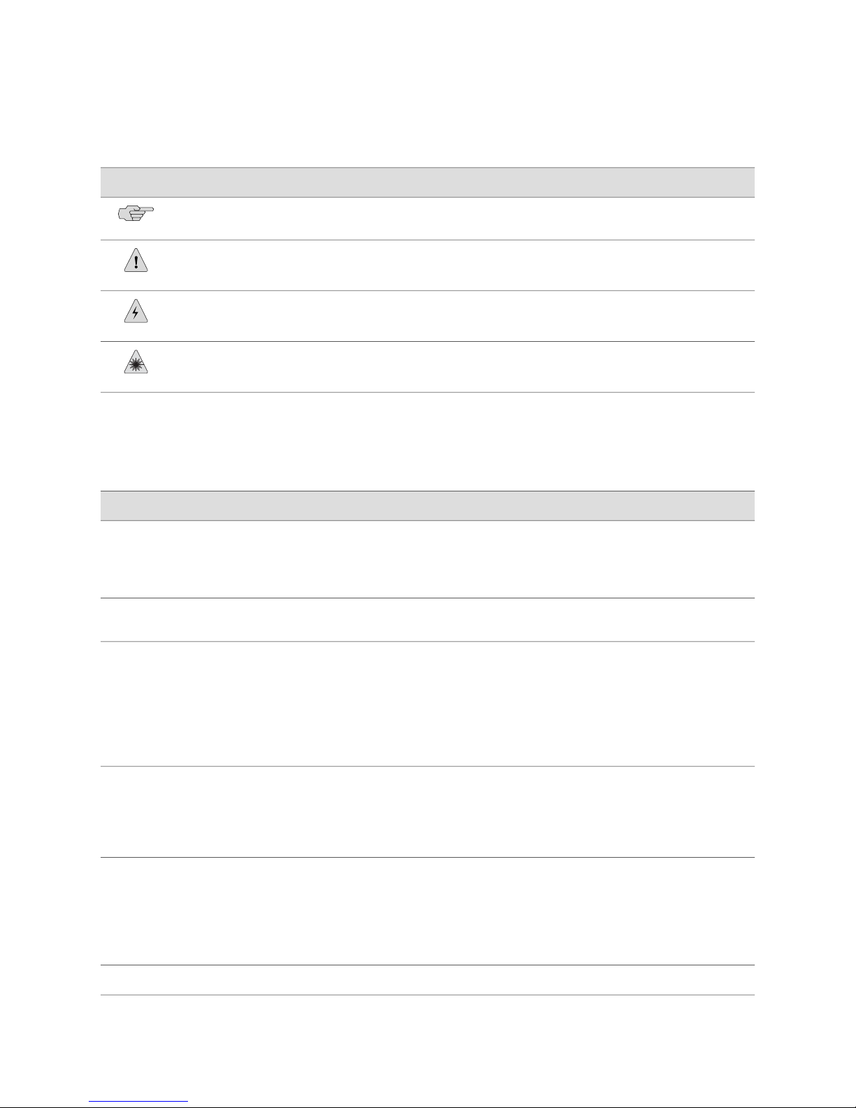
Table 1 on page xvi defines the notice icons used in this guide.
Objectives ■ xv
Page 16
SRX 210 Services Gateway Hardware Guide
Table 1: Notice Icons
Table 2 on page xvi defines the text and syntax conventions used in this guide.
DescriptionMeaningIcon
Indicates important features or instructions.Informational note
Indicates a situation that might result in loss of data or hardware damage.Caution
Alerts you to the risk of personal injury or death.Warning
Alerts you to the risk of personal injury from a laser.Laser warning
Table 2: Text and Syntax Conventions
Bold text like this
Fixed-width text like this
Italic text like this
Italic text like this
Plain text like this
Represents text that you type.
Represents output that appears on the
terminal screen.
Introduces important new terms.
■
Identifies book names.
■
Identifies RFC and Internet draft
■
titles.
Represents variables (options for which
you substitute a value) in commands or
configuration statements.
Represents names of configuration
statements, commands, files, and
directories; IP addresses; configuration
hierarchy levels; or labels on routing
platform components.
ExamplesDescriptionConvention
To enter configuration mode, type the
configure command:
user@host> configure
user@host> show chassis alarms
No alarms currently active
A policy term is a named structure
■
that defines match conditions and
actions.
JUNOS System Basics Configuration
■
Guide
RFC 1997, BGP Communities
■
Attribute
Configure the machine’s domain name:
[edit]
root@# set system domain-name
domain-name
To configure a stub area, include
■
the stub statement at the [edit
protocols ospf area area-id]
hierarchy level.
The console port is labeled
■
CONSOLE.
xvi ■ Documentation Conventions
Enclose optional keywords or variables.< > (angle brackets)
stub <default-metric metric>;
Page 17

Table 2: Text and Syntax Conventions (continued)
About This Guide
ExamplesDescriptionConvention
| (pipe symbol)
# (pound sign)
[ ] (square brackets)
Indention and braces ( { } )
; (semicolon)
J-Web GUI Conventions
Bold text like this
Indicates a choice between the mutually
exclusive keywords or variables on either
side of the symbol. The set of choices is
often enclosed in parentheses for clarity.
Indicates a comment specified on the
same line as the configuration statement
to which it applies.
Enclose a variable for which you can
substitute one or more values.
Identify a level in the configuration
hierarchy.
Identifies a leaf statement at a
configuration hierarchy level.
Represents J-Web graphical user
interface (GUI) items you click or select.
broadcast | multicast
(string1 | string2 | string3)
rsvp { # Required for dynamic MPLS only
community name members [
community-ids ]
[edit]
routing-options {
static {
route default {
nexthop address;
retain;
}
}
}
In the Logical Interfaces box, select
■
All Interfaces.
To cancel the configuration, click
■
Cancel.
> (bold right angle bracket)
Separates levels in a hierarchy of J-Web
selections.
In the configuration editor hierarchy,
select Protocols>Ospf.
List of Technical Publications
The following sections list hardware and software guides and release notes for the
SRX 210 running JUNOS software.
All documents are available at http://www.juniper.net/techpubs/.
Hardware Guides ■ SRX 210 Services Gateway Getting Started Guide—Explains how to quickly set up
an SRX 210 services gateway.
Software Guides ■ JUNOS Software Interfaces and Routing Configuration Guide—Explains how to
configure SRX-series and J-series interfaces for basic IP routing with standard
routing protocols, ISDN service, firewall filters (access control lists), and
class-of-service (CoS) traffic classification.
■ JUNOS Software Security Configuration Guide—Explains how to configure and
manage J-series and SRX-series security services such as stateful firewall policies,
IPsec VPNs, firewall screens, Network Address Translation (NAT), Public Key
Cryptography, chassis clusters, Application Layer Gateways (ALGs), and Intrusion
Detection and Prevention (IDP).
List of Technical Publications ■ xvii
Page 18

SRX 210 Services Gateway Hardware Guide
■ JUNOS Software Administration Guide—Shows how to monitor SRX-series and
J-series devices and routing operations, firewall and security services, system
alarms and events, and network performance. This guide also shows how to
administer user authentication and access, upgrade software, and diagnose
common problems.
■ JUNOS Software CLI Reference—Provides the complete configuration hierarchy
available on SRX-series and J-series devices. This guide also describes the
configuration statements and operational mode commands unique to these
devices.
■ JUNOS Network Management Configuration Guide—Describes enterprise-specific
MIBs for JUNOS software. The information in this guide is applicable to M-series,
T-series, EX-series, SRX-series, and J-series devices.
■ JUNOS System Log Messages Reference—Describes how to access and interpret
system log messages generated by JUNOS software modules and provides a
reference page for each message. The information in this guide is applicable to
M-series, T-series, EX-series, SRX-series, and J-series devices.
Release Notes ■ JUNOS Release Notes—Summarize new features and known problems for a
particular release of JUNOS software, including JUNOS software for J-series and
SRX-series devices. The release notes also contain corrections and updates to
the manuals and software upgrade and downgrade instructions for JUNOS
software.
Obtaining Documentation
To obtain the most current version of all Juniper Networks technical documentation,
see the products documentation page on the Juniper Networks Web site at
http://www.juniper.net/.
To order printed copies of this guide and other Juniper Networks technical documents,
or to order a documentation CD, which contains this guide, contact your sales
representative.
Copies of the Management Information Bases (MIBs) available in a software release
are included on the documentation CDs and at http://www.juniper.net/.
Documentation Feedback
We encourage you to provide feedback, comments, and suggestions so that we can
improve the documentation. You can send your comments to
[email protected], or fill out the documentation feedback form at
http://www.juniper.net/techpubs/docbug/docbugreport.html. If you are using e-mail, be sure
to include the following information with your comments:
■ Document Name
■ Document part number
■ Page number
■ Software release version (not required for Network Operations Guides [NOGs])
xviii ■ Obtaining Documentation
Page 19

Requesting Technical Support
Technical product support is available through the Juniper Networks Technical
Assistance Center (JTAC). If you are a customer with an active J-Care or JNASC support
contract, or are covered under warranty, and need postsales technical support, you
can access our tools and resources online or open a case with JTAC.
■ JTAC policies—For a complete understanding of our JTAC procedures and policies,
review the JTAC User Guide located at
http://www.juniper.net/customers/support/downloads/710059.pdf.
■ Product warranties—For product warranty information, visit
http://www.juniper.net/support/warranty/.
■ JTAC Hours of Operation —The JTAC centers have resources available 24 hours
a day, 7 days a week, 365 days a year.
Self-Help Online Tools and Resources
About This Guide
For quick and easy problem resolution, Juniper Networks has designed an online
self-service portal called the Customer Support Center (CSC) that provides you with
the following features:
■
Find CSC offerings: http://www.juniper.net/customers/support/
■
Search for known bugs: http://www2.juniper.net/kb/
■
Find product documentation: http://www.juniper.net/techpubs/
■ Find solutions and answer questions using our Knowledge Base:
http://kb.juniper.net/
■ Download the latest versions of software and review release notes:
http://www.juniper.net/customers/csc/software/
■ Search technical bulletins for relevant hardware and software notifications:
https://www.juniper.net/alerts/
■ Join and participate in the Juniper Networks Community Forum:
http://www.juniper.net/company/communities/
■
Open a case online in the CSC Case Manager: http://www.juniper.net/cm/
To verify service entitlement by product serial number, use our Serial Number
Entitlement (SNE) Tool located at https://tools.juniper.net/SerialNumberEntitlementSearch/.
Opening a Case with JTAC
You can open a case with JTAC on the Web or by telephone.
■
Use the Case Manager tool in the CSC at http://www.juniper.net/cm/ .
■ Call 1-888-314-JTAC (1-888-314-5822 toll-free in the USA, Canada, and Mexico).
For international or direct-dial options in countries without toll-free numbers, visit
us at http://www.juniper.net/support/requesting-support.html.
Requesting Technical Support ■ xix
Page 20

SRX 210 Services Gateway Hardware Guide
xx ■ Requesting Technical Support
Page 21

Part 1
SRX 210 Services Gateway Overview
■ Introduction to the SRX 210 Services Gateway on page 3
■ SRX 210 Services Gateway Hardware Components and Specifications on page 11
SRX 210 Services Gateway Overview ■ 1
Page 22

SRX 210 Services Gateway Hardware Guide
2 ■ SRX 210 Services Gateway Overview
Page 23

Chapter 1
Introduction to the SRX 210 Services
Gateway
This section includes the following topics:
■ SRX 210 Services Gateway Description on page 3
■ SRX 210 Services Gateway Features and Functions on page 4
■ SRX 210 Services Gateway Software Features and Licenses on page 5
SRX 210 Services Gateway Description
■ Introduction on page 3
■ Types of SRX 210 Services Gateways on page 3
■ Accessing the SRX 210 Services Gateway on page 4
Introduction
The SRX 210 services gateway can be used by the following types of networks,
provided they are connected directly to a traditional private network such as leased
lines, Frame Relay, or Multi Protocol Label Switching (MPLS) networks:
■ Branch offices
■ Small enterprises
■ Fixed telecommuters
■ Small standalone business deployments
The device can also be used for branch offices where the public Internet is used as
an alternative to a traditional private wide area network (WAN).
Types of SRX 210 Services Gateways
There are three types of SRX 210 services gateways:
■ Low Memory
■ High Memory
■ Power over Ethernet
SRX 210 Services Gateway Description ■ 3
Page 24
SRX 210 Services Gateway Hardware Guide
Accessing the SRX 210 Services Gateway
You can use two user interfaces to monitor, configure, troubleshoot, and manage
the SRX 210 services gateway:
■ J-Web interface: Web-based graphical interface that allows you to operate a
services gateway without commands. The J-Web interface provides access to all
JUNOS functionality and features.
■ JUNOS command-line interface (CLI): Juniper Networks command shell that runs
on top of a UNIX-based operating system kernel. The CLI is a straightforward
command interface. On a single line, you type commands that are executed
when you press the Enter key. The CLI provides command Help and command
completion.
The SRX 210 services gateway runs the JUNOS operating system.
Related Topics SRX 210 Services Gateway Chassis on page 11■
■ SRX 210 Services Gateway Features and Functions on page 4
■ SRX 210 Services Gateway Software Features and Licenses on page 5
SRX 210 Services Gateway Features and Functions
The SRX 210 services gateway provides the following features:
■ Stable, reliable, and efficient IP routing
■ WAN connectivity
■ LAN connectivity
The SRX 210 services gateway is a security optimized, fixed processing system that
provides the following functions for the Low Memory, High Memory, and Power over
Ethernet (PoE) types listed in Table 3 on page 4.
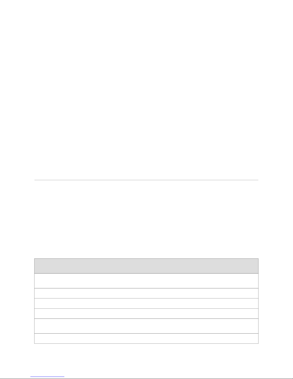
Table 3: SRX 210 Services Gateway Features
Features
(IPsec)
SRX 210 Services Gateway
Low Memory
SRX 210 Services Gateway
High Memory
SRX 210 Services Gateway
PoE
YesYesYesInternet Protocol Security
YesYesYesVirtual private network (VPN)
forwarding
4 ■ SRX 210 Services Gateway Features and Functions
YesYesYesWeb filtering
YesYesYesFirewall services
YesYesYesContiguous memory for
YesYesYesReal time clock (RTC) support
Page 25
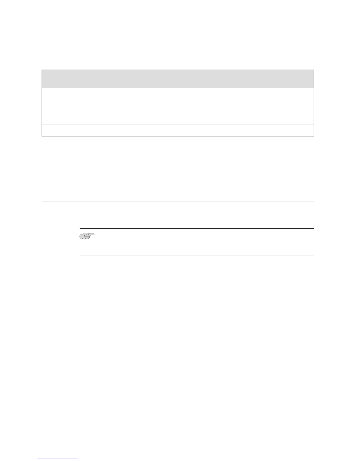
Table 3: SRX 210 Services Gateway Features (continued)
Chapter 1: Introduction to the SRX 210 Services Gateway
Features
SRX 210 Services Gateway
Low Memory
SRX 210 Services Gateway
High Memory
NoNoPoE support
Related Topics ■ SRX 210 Services Gateway Description on page 3
■ Accessing the SRX 210 Services Gateway
■ SRX 210 Services Gateway Software Features and Licenses on page 5
■ SRX 210 Services Gateway Chassis on page 11
SRX 210 Services Gateway Software Features and Licenses
The SRX 210 services gateway provides the software features listed in
Table 4 on page 6.
NOTE: You must purchase a separate software license to obtain some software
features.
SRX 210 Services Gateway
PoE
1 GB1 GB512 MBDDR memory
PoE support on 4 ports (2
Gigabit Ethernet and 2 Fast
Ethernet)
150 Watts60 Watts60 WattsPower supply adapter
SRX 210 Services Gateway Software Features and Licenses ■ 5
Page 26

SRX 210 Services Gateway Hardware Guide
Table 4: SRX 210 Services Gateway Software Features and Licenses
SRX 210 Services Gateway FeatureFeature
Category
Multicast
Open Shortest Path First (OSPF)Routing and
Border Gateway Protocol (BGP)
Routing Information Protocol version 1 (RIPv1) and version 2 (RIPv2)
Static routes
Intermediate System-to-Intermediate System (IS-IS)
Connectionless Network Services (CLNS):
NOTE: CLNS is available only in packet-based mode.
End System-to-Intermediate System (ES-IS) protocol
■
IS-IS extensions
■
BGP extensions
■
Static routes
■
Multiprotocol Label Switching (MPLS):
NOTE: MPLS is available only in packet-based mode.
Layer 2 and Layer 3 virtual private networks (VPNs)
■
VPN routing and forwarding (VRF) table labels
■
Traffic engineering protocols such as Label Distribution Protocol (LDP) and Resource Reservation
■
Protocol (RSVP)
Protocols
Management
NOTE: Security features cannot be configured when MPLS/IPv6 is used.
Multicast:
Internet Group Management Protocol (IGMP)
■
Protocol Independent Multicast (PIM)
■
Distance Vector Multicast Routing Protocol (DVMRP)
■
Single-source multicast
■
IPv4Internet
IPv6 routing and forwarding
Static addressesIP Address
Dynamic Host Configuration Protocol (DHCP)
6 ■ SRX 210 Services Gateway Software Features and Licenses
Page 27

Chapter 1: Introduction to the SRX 210 Services Gateway
Table 4: SRX 210 Services Gateway Software Features and Licenses (continued)
SRX 210 Services Gateway FeatureFeature
Category
Encapsulation
Ethernet:
Media access control (MAC) encapsulation
■
802.1p tagging
■
Point-to-Point Protocol over Ethernet (PPPoE)
■
Circuit cross-connect (CCC)
■
Translational cross-connect (TCC)
■
Synchronous Point-to-Point Protocol (PPP)
Frame Relay
High-level Data Link Control (HDLC)
802.1Q filtering and forwarding
Multilink Frame Relay (MFR)
Multilink PPP
Common CriteriaSecurity
Network attack detection
Denial-of-service (DoS) and distributed denial-of-service (DDoS) protection
Generic routing encapsulation (GRE), IP-over-IP, and IP Security (IPsec) tunnels
Advanced Encryption Standard (AES) 128-bit, 192-bit, and 256-bit
56-bit Data Encryption Standard (DES) and 168-bit 3DES encryption
MD5 and Secure Hash Algorithm (SHA-1) authentication
Stateful firewall packet filters
Network Address Translation (NAT)
Unified Threat Management (UTM)
NOTE: Separate license is required for UTM.
Intrusion Detection and Prevention (IDP)
NOTE:
Separate license is required for IDP.
■
IDP HA is not supported in this release.
■
SRX 210 Services Gateway Software Features and Licenses ■ 7
Page 28

SRX 210 Services Gateway Hardware Guide
Table 4: SRX 210 Services Gateway Software Features and Licenses (continued)
SRX 210 Services Gateway FeatureFeature
Category
Chassis
Clustering
Management
Logging and
Monitoring
Switching
Chassis clustering is supported on the device. Chassis cluster control and chassis cluster data are supported
over a single physical interface, thereby minimizing the number of chassis cluster interfaces required
on the device. One of the ports on the front panel of the base system is used as the chassis cluster port.
J-Web browser interface—for services gateway configuration and managementSystem
JUNOScript XML application programming interface (API)
JUNOS command-line interface (CLI)—for services gateway configuration and management through the
console, Telnet, SSH, or J-Web CLI terminal
Simple Network Management Protocol version 1 (SNMPv1) and SNMPv2
Network and Security Manager (NSM)
J-Flow flow monitoring and accountingTraffic Analysis
Packet capture (PCAP)
Real-time performance monitoring (RPM)
System logActivity
J-Web event viewer
Traceroute
Access switching provided by onboard Gigabit Ethernet ports
■
VLANs
■
STP/RSTP/MSTP
■
GVRP
■
LACP
■
802.1x (Port based network authentication)
■
8 ■ SRX 210 Services Gateway Software Features and Licenses
Page 29

Chapter 1: Introduction to the SRX 210 Services Gateway
Table 4: SRX 210 Services Gateway Software Features and Licenses (continued)
SRX 210 Services Gateway FeatureFeature
Category
Administration
Supports the following external administrator databases:
RADIUS
■
TACACS+
■
Autoinstallation
Configuration rollback
Button-operated configuration rescue (CONFIG)
Confirmation of configuration changes
Software upgrades
Supports the following features for automating network operations and troubleshooting:
Commit scripts
■
Operation scripts
■
Event policies
■
Related Topics ■ SRX 210 Services Gateway Description on page 3
■ SRX 210 Services Gateway Chassis on page 11
■ SRX 210 Services Gateway Features and Functions on page 4
SRX 210 Services Gateway Software Features and Licenses ■ 9
Page 30

SRX 210 Services Gateway Hardware Guide
10 ■ SRX 210 Services Gateway Software Features and Licenses
Page 31
Chapter 2
SRX 210 Services Gateway Hardware
Components and Specifications
The hardware components and specifications of the SRX 210 services gateway are
described in the following topics:
■ SRX 210 Services Gateway Chassis on page 11
■ SRX 210 Services Gateway Front Panel on page 12
■ SRX 210 Services Gateway Back Panel on page 19
■ SRX 210 Services Gateway Boot Devices on page 20
■ SRX 210 Services Gateway Cooling System on page 21
■ SRX 210 Services Gateway Power Supply on page 22
■ SRX 210 Services Gateway Mini-Physical Interface Modules on page 22
■ SRX 210 Services Gateway 3G ExpressCard on page 32
■ SRX 210 Services Gateway PoE Overview on page 35
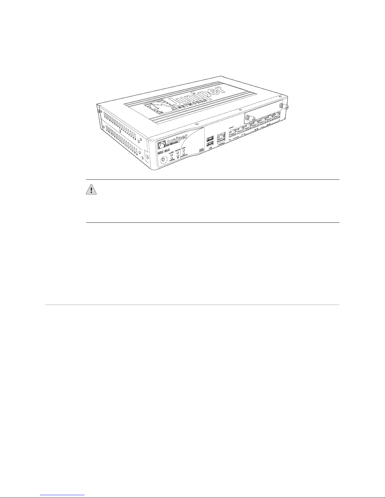
SRX 210 Services Gateway Chassis
The SRX 210 services gateway chassis is a rigid sheet metal structure that houses all
the other hardware components (see Figure 1 on page 12).
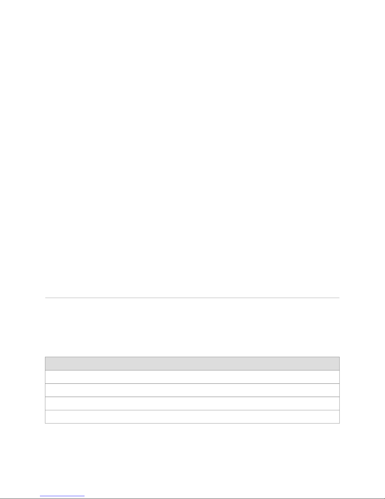
Table 5 on page 11 provides information on the physical specifications of the device.
Table 5: Physical Specifications for the SRX 210 Services Gateway
ValuePhysical Specification
1 Rack Unit (RU)Chassis height
11 in. (280 mm)Chassis width
7 in. (179 mm)Chassis depth
3.66 lb (1.66 kg)Chassis weight
SRX 210 Services Gateway Chassis ■ 11
Page 32
SRX 210 Services Gateway Hardware Guide
Figure 1: SRX 210 Services Gateway
CAUTION: Before removing or installing components of a functioning services
gateway, attach an electrostatic discharge (ESD) strap to an ESD point and place the
other end of the strap around your bare wrist. Failure to use an ESD strap could result
in damage to the services gateway.
Related Topics ■ SRX 210 Services Gateway Description on page 3
■ SRX 210 Services Gateway Front Panel on page 12
■ SRX 210 Services Gateway Back Panel on page 19
■ Monitoring the SRX 210 Services Gateway Components using LEDs on page 122
■ SRX 210 Services Gateway Electrical Safety Guidelines and Warnings on page 150
SRX 210 Services Gateway Front Panel
The front panel of the SRX 210 services gateway consists of the following components:
■ Fast Ethernet ports
■ Gigabit Ethernet ports
■ Power button
■ Reset Config button
■ Console port
■ USB ports
■ Mini-Physical Interface Module (Mini-PIM) slot
■ Front panel LEDs
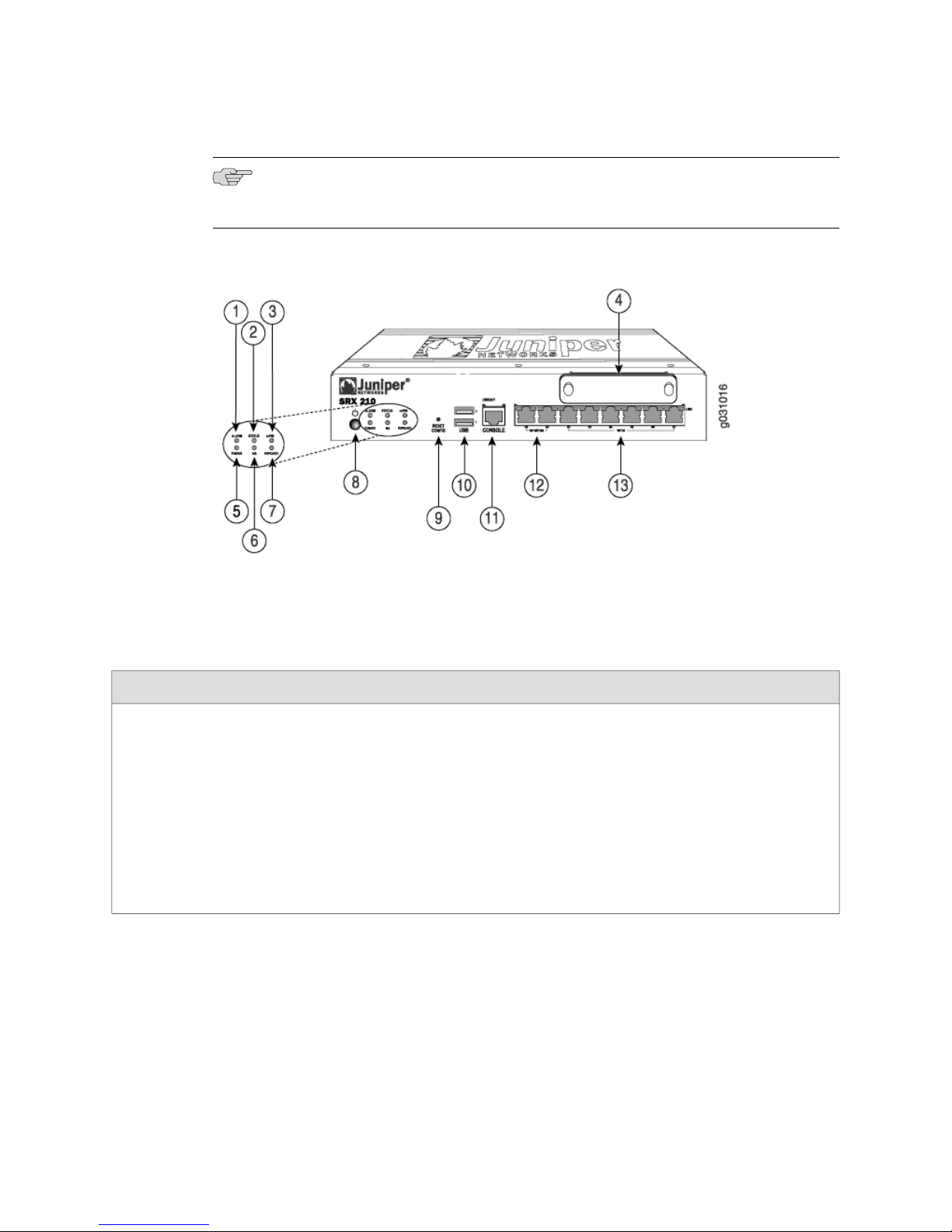
Figure 2 on page 13 shows the front panel of the SRX 210 services gateway.
12 ■ SRX 210 Services Gateway Front Panel
Page 33
Chapter 2: SRX 210 Services Gateway Hardware Components and Specifications
NOTE: The numbers in Figure 2 on page 13 correspond to the numbers in
Table 6 on page 13.
Figure 2: SRX 210 Services Gateway Front Panel Components
Table 6 on page 13 provides information about the front panel components of the
services gateway.
Table 6: SRX 210 Services Gateway Front Panel Components
Alarm LED1
Left side of the front
panel
The Alarm LED has the
following indicator colors:
■
■
■
Red and steadily on
indicates a critical
alarm.
Amber and steadily on
indicates a major
alarm.
Off indicates that there
are currently no
alarms.
UsageDescriptionLocationComponentNumber
The Alarm LED can be used
to gather information on
critical or major alarms or to
determine if the device is
functioning normally.
SRX 210 Services Gateway Front Panel ■ 13
Page 34

SRX 210 Services Gateway Hardware Guide
Table 6: SRX 210 Services Gateway Front Panel Components (continued)
UsageDescriptionLocationComponentNumber
Status LED2
Left side of the front
panel
The Status LED has the
following indicator colors:
Green and steadily on
■
indicates that the
device is functioning
The Status LED can be used
to determine whether the
device is starting up, is
functioning normally, or has
failed.
normally.
Amber and steadily on
■
indicates that the
device is starting up.
Red and steadily on
■
indicates that the
device has failed.
Mini-PIM LED3
Left side of the front
panel
The Mini-Physical Interface
Modules (Mini-PIMs) LED
has the following indicator
colors:
Green and steadily on
■
The Mini-PIM LED can be
used to determine if the
Mini-PIM is present and
detected by the device.
indicates that the
Mini-PIM is functioning
normally.
Off indicates that the
■
Mini-PIM is not present
or not detected by the
device.
Mini-PIM slot4
Right side of the front
panel
The Mini-Physical Interface
Module (Mini-PIM) slot has
the following characteristics:
Consists of one slot for
■
a Mini-PIM
Supports the T1/E1
■
Mini-PIM
Supports the 1-Port
■
SFP Mini-PIM
Supports the ADSL 2+
■
Mini-PIM
The Mini-PIM slot can be
used as follows:
To provide LAN and
■
WAN functionality
To provide connections
■
to the T1 or E1 network
media types
To provide connectivity
■
to a Gigabit Ethernet
interface
To provide connectivity
■
to the ADSL 2+
network media types
14 ■ SRX 210 Services Gateway Front Panel
Page 35

Chapter 2: SRX 210 Services Gateway Hardware Components and Specifications
Table 6: SRX 210 Services Gateway Front Panel Components (continued)
UsageDescriptionLocationComponentNumber
Power LED5
Left side of the front
panel
The Power LED has the
following indicator colors:
Green and steadily on
■
The Power LED can be used
to determine if the device is
receiving power.
indicates that the
device is functioning
normally.
Amber and steadily on
■
indicates that the
Power button has been
pressed and quickly
released. The device is
gracefully shutting
down.
Off indicates that the
■
device is not receiving
power.
HA LED6
Left side of the front
panel
The HA LED has the
following indicator colors:
Green and steadily on
■
The HA LED can be used to
determine if high availability
is enabled on the device.
indicates that all HA
links are available.
Red and steadily on
■
indicates that the HA
links are not working
as expected.
Amber and steadily on
■
indicates that some HA
links are not working
as expected.
Off indicates that HA is
■
not enabled.
SRX 210 Services Gateway Front Panel ■ 15
Page 36

SRX 210 Services Gateway Hardware Guide
Table 6: SRX 210 Services Gateway Front Panel Components (continued)
UsageDescriptionLocationComponentNumber
ExpressCard LED7
Left side of the front
panel
The ExpressCard LED has
the following indicator
colors:
Green and steadily on
■
This LED provides
information on the
functioning of the
ExpressCard slot.
indicates that the
ExpressCard is plugged
in and data call is
established.
Red and steadily on
■
Indicates that the
■
ExpressCard
plugged in is
faulty or not
detected by the
device.
Indicates that the
■
ExpressCard is
plugged in but not
registered with
the Network.
Yellow and steadily on
■
indicates that the
ExpressCard is plugged
in and registered with
the Network.
Off indicates that the
■
ExpressCard is not
plugged in.
Power button8
Left side of the front
panel
The power button powers
the device on and off.
The power button has status
indicators on the front panel
that indicate whether the
power supply is functioning
normally.
Reset Config button9
Recessed in the left side
of the front panel
The Reset Config button
returns the device to the
default configuration.
The Reset Config button is
used to remove the current
configuration and reset the
device to the default
configuration.
The button is recessed in the
front panel to prevent it from
being pressed accidentally.
Pressing and holding the
Reset Config button for 15
seconds or more deletes all
configurations on the device
and loads and commits the
factory configuration.
16 ■ SRX 210 Services Gateway Front Panel
Page 37

Chapter 2: SRX 210 Services Gateway Hardware Components and Specifications
Table 6: SRX 210 Services Gateway Front Panel Components (continued)
UsageDescriptionLocationComponentNumber
10
(USB) ports
Center of the front panelUniversal Serial Bus
The USB ports have the
following characteristics:
Consist of two ports
■
Function in the
■
following modes:
Low speed
■
Full speed
■
High speed
■
Compliant with USB
■
revision 2.0
The USB ports can be used
as follows:
To support a USB
■
storage device that
functions as a
secondary boot device
in case of the internal
flash failure on startup,
if the USB storage
device is installed and
configured.
NOTE: You must install and
configure the USB storage
device on the USB port to
use it as secondary boot
device. Also, the USB device
must have JUNOS installed.
To provide the USB
■
interfaces that are used
to communicate with
many types of Juniper
supported USB storage
devices.
Contact a customer service
representative for more
information.
Center of the front panelConsole port11
The Console port has the
following characteristics:
Consists of one port
■
Uses an RJ-45 serial
■
cable connector
Supports the RS-232
■
(EIA-232) standard
The Console port can be
used as follows:
To provide the Console
■
interface
To function as a
■
management port to log
into a device directly
To configure the device
■
using the CLI
SRX 210 Services Gateway Front Panel ■ 17
Page 38

SRX 210 Services Gateway Hardware Guide
Table 6: SRX 210 Services Gateway Front Panel Components (continued)
UsageDescriptionLocationComponentNumber
Gigabit Ethernet ports12
Right side of the front
panel
The Gigabit Ethernet ports
have the following
characteristics:
Consist of two fixed
■
ports
Labeled as port 0/0 and
■
port 0/1 on the front
panel
Use an RJ-45 connector
■
Provide link speeds of
■
10/100/1000 Mbps
Operate in full-duplex
■
and half-duplex modes
Support flow control
■
Support
■
The Gigabit Ethernet ports
can be used as follows:
To function as front-end
■
network ports
To provide LAN and
■
WAN connectivity to
hubs, switches, local
servers, and
workstations
To forward incoming
■
data packets to the
device
To receive outgoing
■
data packets from the
device
autonegotiation
Both Gigabit Ethernet ports
support PoE.
NOTE: This is applicable
only for PoE version of the
SRX 210 services gateway.
Fast Ethernet ports13
Right side of the front
panel
The Fast Ethernet ports
have the following
characteristics:
Consist of six fixed
■
ports
Labeled as port 0/2 to
■
port 0/7 on the front
panel
Provide link speeds of
■
10/100 Mbps
Operate in the
■
full-duplex and
The Fast Ethernet ports can
be used as follows:
To provide LAN
■
connectivity to hubs,
switches, local servers,
and workstations
To forward incoming
■
data packets to the
device
To receive outgoing
■
data packets from the
device
half-duplex modes
Support flow control
■
Support
■
autonegotiation
SRX 210 Services Gateway Ethernet Ports LEDs
18 ■ SRX 210 Services Gateway Front Panel
The first two Fast Ethernet
ports support PoE.
NOTE: This is applicable
only for PoE version of the
SRX 210 services gateway.
Page 39
Chapter 2: SRX 210 Services Gateway Hardware Components and Specifications
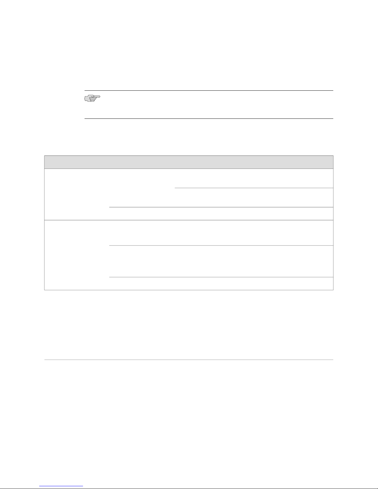
On the SRX 210 services gateway, each Ethernet port (Gigabit Ethernet port and Fast
Ethernet port) has two LEDs, a TX/RX/LINK LED on the left side and a PoE (Power
over Ethernet) LED on the right side of the chassis.
NOTE: The PoE LED is enabled only on the PoE variant of the SRX 210 services
gateway. For non-PoE gateways, the PoE LED remains off.
Table 7 on page 19 describes the built-in Ethernet port LEDs.
Table 7: SRX 210 Services Gateway Ethernet Port LEDs
DescriptionStateColorFunction
BlinkingGreenTX/RX/LINK
Steady
SteadyGreenPoE Status
SteadyYellow
Related Topics ■ SRX 210 Services Gateway Chassis on page 11
■ SRX 210 Services Gateway Back Panel on page 19
■ Monitoring the SRX 210 Services Gateway Components using LEDs on page 122
■ SRX 210 Services Gateway Boot Devices on page 20
Link is up. Data communication is
taking place.
Link is up. No data communication is
taking place.
Link is down.OffUnlit
PoE (Power over Ethernet) is on and
the connected Power Device is
receiving power.
PoE (Power over Ethernet) is on, but
the connected Power Device is not
receiving power (fault or not enough
power).
PoE is off.OffUnlit
SRX 210 Services Gateway Back Panel
The back panel of the SRX 210 services gateway consists of the following components:
■ ExpressCard slot
■ Grounding point
■ Power supply
Figure 3 on page 20 illustrates the back panel of the SRX 210 services gateway.
SRX 210 Services Gateway Back Panel ■ 19
Page 40
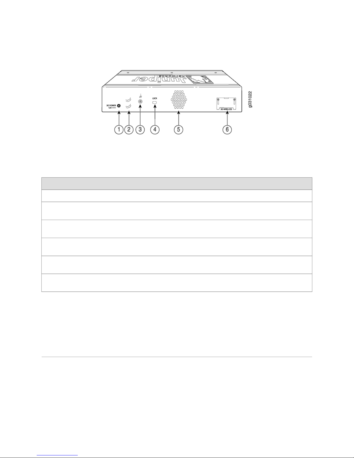
SRX 210 Services Gateway Hardware Guide
Figure 3: SRX 210 Services Gateway Back Panel
Table 8 on page 20 provides details about components available on the back panel
of the SRX 210 services gateway.
Table 8: SRX 210 Services Gateway Back Panel Components
DescriptionLocationComponentNumber
Provides the power supply for the device.Right side of back panelPower supply point1
Right side of back panelCable tie holder2
Provides the support to hold the power cord
onto the power supply point.
Right side of back panelGrounding point3
Provides the grounding-cable connection
point.
Right side of back panelLock4
Provides the option to lock and secure the
device to the installation site.
Center of back panelExhaust vents5
Provides the outlet for the fan to push the air
out of the chassis.
Left side of back panelExpressCard slot6
Provides the connection to a 3G wireless
ExpressCard.
Related Topics ■ SRX 210 Services Gateway Chassis on page 11
■ SRX 210 Services Gateway Front Panel on page 12
■ SRX 210 Services Gateway Boot Devices on page 20
■ SRX 210 Services Gateway Power Supply on page 22
SRX 210 Services Gateway Boot Devices
The SRX 210 services gateway can boot from two devices:
■ Internal flash
■ External USB storage device
Related Topics ■ SRX 210 Services Gateway Chassis on page 11
■ SRX 210 Services Gateway Front Panel on page 12
20 ■ SRX 210 Services Gateway Boot Devices
Page 41
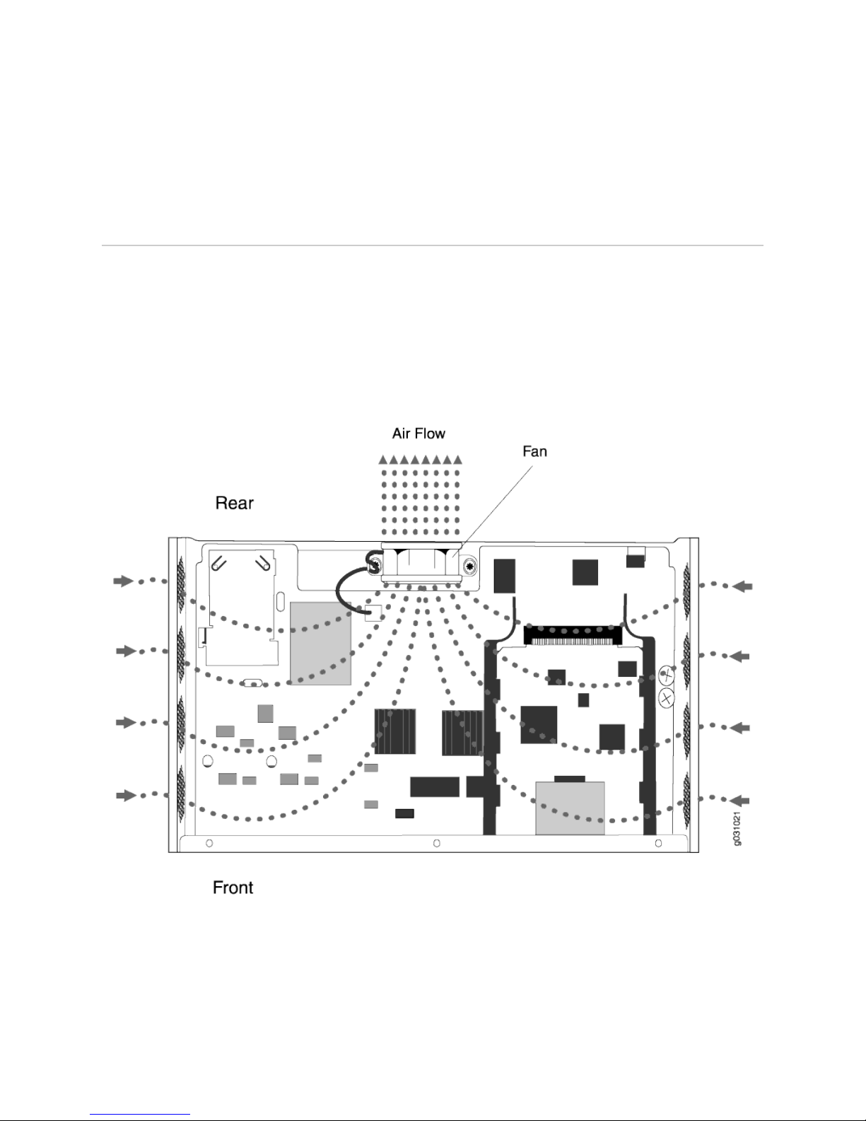
Chapter 2: SRX 210 Services Gateway Hardware Components and Specifications
■ SRX 210 Services Gateway Back Panel on page 19
■ SRX 210 Services Gateway Power Supply on page 22
SRX 210 Services Gateway Cooling System
The fan is the cooling system component provided in the SRX 210 services gateway
to keep all components within the acceptable temperature range.
The services gateway has a single fixed fan (see Figure 4 on page 21).
The fan controller monitors the temperature of the system. Under normal operating
conditions, the fan functions at lower than full speed.
Figure 4: Airflow Through the SRX 210 Services Gateway Chassis
Related Topics ■ SRX 210 Services Gateway Chassis on page 11
■ SRX 210 Services Gateway Front Panel on page 12
■ SRX 210 Services Gateway Back Panel on page 19
■ SRX 210 Services Gateway Power Supply on page 22
SRX 210 Services Gateway Cooling System ■ 21
Page 42

SRX 210 Services Gateway Hardware Guide
SRX 210 Services Gateway Power Supply
The power supply for the SRX 210 services gateway is external. You must use the
power supply provided by Juniper Networks to provide power to the services gateway.
Related Topics ■ SRX 210 Services Gateway Chassis on page 11
■ SRX 210 Services Gateway Front Panel on page 12
■ SRX 210 Services Gateway Back Panel on page 19
■ SRX 210 Services Gateway Boot Devices on page 20
■ SRX 210 Services Gateway Cooling System on page 21
■ Monitoring the SRX 210 Services Gateway Power System on page 125
SRX 210 Services Gateway Mini-Physical Interface Modules
This section includes the following topics:
■ Mini-Physical Interface Modules on the SRX 210 Services Gateway on page 22
■ SRX 210 Services Gateway T1/E1 Mini-Physical Interface Module on page 23
■ SRX 210 Services Gateway 1-Port SFP Mini-Physical Interface Module on page 26
■ SRX 210 Services Gateway ADSL 2+ Mini-Physical Interface Module on page 29
Mini-Physical Interface Modules on the SRX 210 Services Gateway
A Mini-Physical Interface Module (Mini-PIM) is a network interface card that is installed
on the SRX 210 services gateway to provide physical connections to a LAN or a WAN.
The Mini-PIM receives incoming packets from the network and transmits outgoing
packets to the network.
The SRX 210 services gateway supports the following Mini-PIMs:
■ T1/E1 Mini-PIM
■ 1-port Small Form factor Pluggable (SFP) Mini-PIM
■ ADSL 2+ Mini-PIM
The Mini-PIMs supported on the SRX 210 services gateway are field-replaceable. The
field replaceable Mini-PIMs are removable and insertable into the device. You can
install a Mini-PIM into the Mini-PIM slot available on the front panel of the services
gateway chassis.
CAUTION: The Mini-PIMs available on the SRX 210 services gateway are not
hot-swappable. You need to power off the device before removing or installing
Mini-PIMs.
Related Topics ■ SRX 210 Services Gateway T1/E1 Mini-Physical Interface Module on page 23
■ SRX 210 Services Gateway 1-Port SFP Mini-Physical Interface Module on page 26
22 ■ SRX 210 Services Gateway Power Supply
Page 43
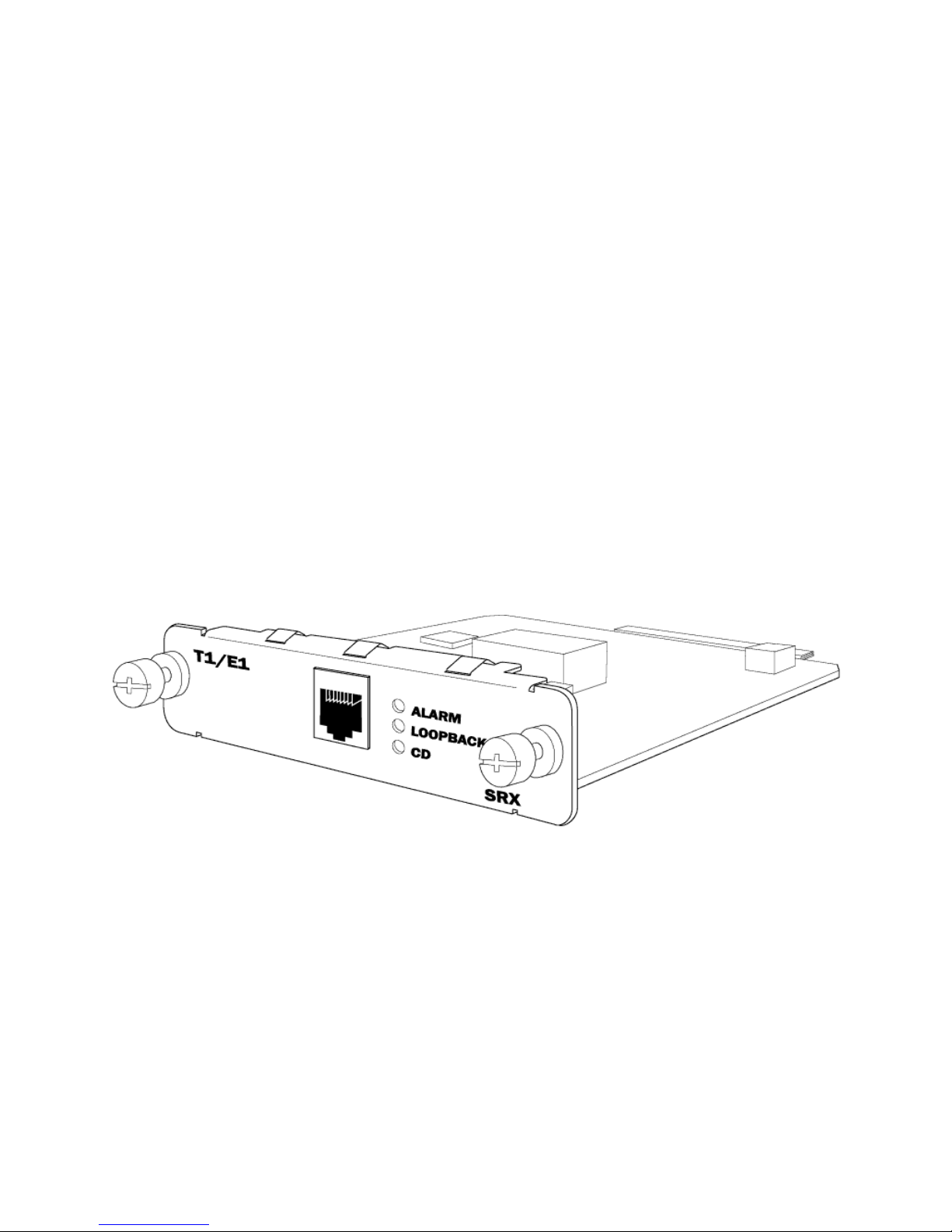
Chapter 2: SRX 210 Services Gateway Hardware Components and Specifications
■ SRX 210 Services Gateway ADSL 2+ Mini-Physical Interface Module on page 29
■ Removing a Blank Mini-Physical Interface Module Faceplate from the SRX 210
Services Gateway on page 116
■ Removing a Mini-Physical Interface Module from the SRX 210 Services
Gateway on page 117
■ Installing a Mini-Physical Interface Module in the SRX 210 Services
Gateway on page 118
SRX 210 Services Gateway T1/E1 Mini-Physical Interface Module
■ T1/E1 Mini-Physical Interface Module on page 23
T1/E1 Mini-Physical Interface Module
The T1/E1 Mini-Physical Interface Module (Mini-PIM) provides the physical connection
to T1 or E1 network media types and also performs T1 or E1 framing and line-speed
signaling.
Figure 5 on page 23 shows the T1/E1 Mini-PIM front panel.
Figure 5: T1/E1 Mini-Physical Interface Module Front Panel
Supported Standards
The T1/E1 Mini-PIM supports the following standards:
■ ANSI TI.107, TI.102
■ GR 499-core, GR 253-core
■ AT&T Pub 54014
■ ITU G.751, G.703
SRX 210 Services Gateway T1/E1 Mini-Physical Interface Module ■ 23
Page 44

SRX 210 Services Gateway Hardware Guide
Key Features
The T1/E1 Mini-PIM provides the following key features:
■ Integrated Channel Service Unit (CSU) or Data Service Unit (DSU) to eliminate
the need for a separate external device
■ 56-Kbps and 64-Kbps operating modes
■ Independent internal and external clocking option
■ Alarm reporting with a 24-hour history maintained
■ Loopback, BERT, FDL (T1 only), and Long Buildout (T1 only) diagnostics
■ Multilink Frame Relay and Multilink PPP support
■ Complete configuration and management by CLI and J-Web
LEDs
The T1/E1 Mini-PIM has three LEDs. Table 9 on page 24 shows the LED states.
Table 9: T1/E1 Mini-PIM LED States
Specifications
Table 10 on page 24 describes the physical specifications of the T1/E1 Mini-PIM.
On steadilyYellowAlarm
Off
On steadilyYellowLoopback
DescriptionStatusColor IndicationLED
Indicates that there is a local or remote
alarm; device has detected a failure
Indicates that there are no alarms or
failures
Indicates that a loopback or line state is
detected
Indicates that the loopback is not activeOff
Indicates that the Mini-PIM link is up.On steadilyGreenCarrier Detector (CD)
Indicates that carrier detect is not activeOff
Table 10: T1/E1 Mini-PIM Physical Specifications
Dimensions (H x W x L)
24 ■ SRX 210 Services Gateway T1/E1 Mini-Physical Interface Module
ValueDescription
0.80” H x 3.75” W x 5.9” L
(2.0 cm x 9.5 cm x 14.5 cm )
0.18 lb (82g)Weight
Page 45
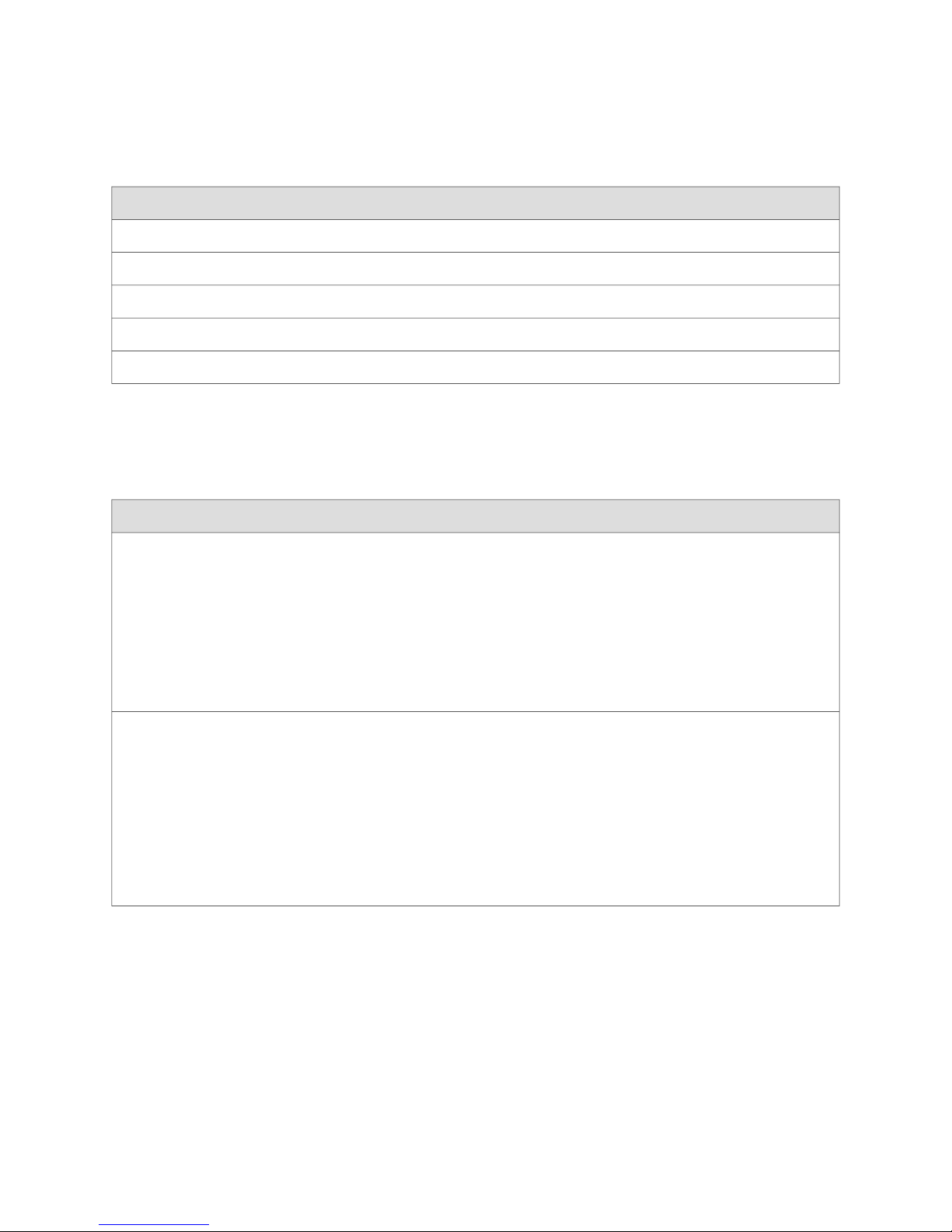
Chapter 2: SRX 210 Services Gateway Hardware Components and Specifications
Table 10: T1/E1 Mini-PIM Physical Specifications (continued)
ValueDescription
RJ-48Connector type
Mini-PIMForm factor
32°F through 104°F (0°C through 40°C)Environmental operating temperature
–40°F through 158°F (–40°C through 70°C)Storage temperature
5% to 90% noncondensingRelative humidity
Network Interface Specifications
The T1/E1 Mini-PIM has the following specifications:
Network interface
specifications
HDLC features
Transmit bit rate: 1.544 Mbps
Receive bit rate: 1.544 Mbps
Line encoding: AMI/B8ZS
Mode: Framed Clear Channel
Fractional Framing: Superframe (D4/SF) Extended
Superframe (ESF)
N x 64 Kbps or N x 56 Kbps, nonchannelized data
rates (T1:N=1 to 24)
CRC 16/32
Shared Flag
Idle flag/fill
Counters: Runts, Giants, FCS, Error, Abort Error,
Align Error
Loopback Diagnostics
E1 SpecificationsT1 SpecificationSpecification
Transmit bit rate: 2.048 Mbps
Receive bit rate: 2.048 Mbps
Line encoding: HDB3
Modes: Framed Clear Channel, Unframed Clear
Channel
Fractional Framing: G704 without CRC4 Unframed
N x 64 Kbps or N x 56 Kbps, nonchannelized data
rates (E1:n=1 to 31)
CRC 16/32
Shared Flag
Idle flag/fill
Counters: Runts, Giants, FCS, Error, Abort Error,
Align Error
■ Local, Remote, Payload
■ Test patterns (BERT)
■ All ones
■ All zeros
■ Alternating ones and zeros (AA/55)
SRX 210 Services Gateway T1/E1 Mini-Physical Interface Module ■ 25
Page 46

SRX 210 Services Gateway Hardware Guide
■ 1:3 or 1 in 4 pattern
■ 1:7 or 1 in 8 pattern
■ 3:24 - 3 bits set in every 24 bits
■ QRSS20 (Modified PRBS 2^20-1, with 14 zero suppression)
■ PRBS 2^7-1 - PRBS 2^9-1 (as specified in ITU-T O.153)
■ PRBS 2^11-1 (as specified in ITU-T O.153)/2047 pattern
■ PRBS 2^15-1 (as specified in ITU-T O.151/O.153)
■ PRBS 2^20-1 (as specified in ITU-T O.153)
■ Programmable word or 32-bit programmable pattern
■ Network (T1) alarms
■ LOS, LOF, AIS, YLW
Related Topics ■ Mini-Physical Interface Modules on the SRX 210 Services Gateway on page 22
■ SRX 210 Services Gateway 1-Port SFP Mini-Physical Interface Module on page 26
■ SRX 210 Services Gateway ADSL 2+ Mini-Physical Interface Module on page 29
■ Removing a Mini-Physical Interface Module from the SRX 210 Services
Gateway on page 117
■ Installing a Mini-Physical Interface Module in the SRX 210 Services
Gateway on page 118
SRX 210 Services Gateway 1-Port SFP Mini-Physical Interface Module
This section includes the following topic:
■ 1-Port SFP Mini-Physical Interface Module on page 26
1-Port SFP Mini-Physical Interface Module
The 1-Port Small Form factor Pluggable (SFP) Mini-Physical Interface Module
(Mini-PIM) provides connectivity to a single Gigabit Ethernet device or network.
Figure 6 on page 27 shows the front panel of 1-Port SFP Mini-PIM front panel.
26 ■ SRX 210 Services Gateway 1-Port SFP Mini-Physical Interface Module
Page 47
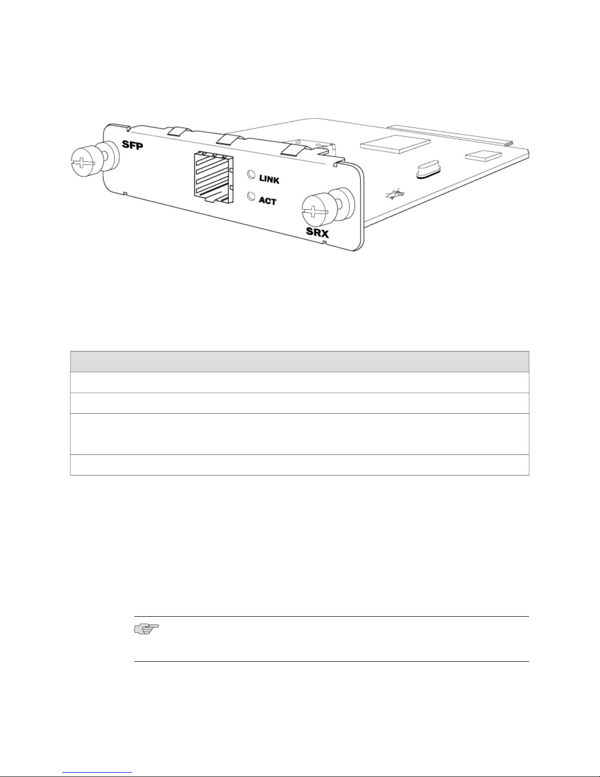
Chapter 2: SRX 210 Services Gateway Hardware Components and Specifications
Figure 6: 1-Port SFP Mini-PIM Front Panel
Supported 1-Port SFP Modules
You can customize the Ethernet interface type by using different 1-Port SFP modules.
Table 11 on page 27 shows the available 1-Port SFP modules.
Table 11: 1-Port SFP Mini-Physical Interface Modules
JX-SFP-1FE-FX
100BASE-LX
Key Features
The 1-Port SFP Mini-PIM has the following key features:
■ Enables you to install and remove transceivers without powering down the device
■ Provides real-time visual status of connectivity and traffic flows
■ Provides Link Up/Down alarm
■ Supports different transceiver types
ConnectorInterface TypeProduct Number
LCGbE SFP, LC connector, LX transceiverJX-SFP-1GE-LX
LCGbE SFP, LC connector, SX transceiverJX-SFP-1GE-SX
LC100BASE-SX
RJ-451000BASE-T SFPJX-SFP-1000BASE-T
NOTE: The 1-Port SFP Mini-PIM with Gigabit Ethernet connector provides 1000 Mbps
link speed. Actual bandwidth is limited to 100 Mbps.
SRX 210 Services Gateway 1-Port SFP Mini-Physical Interface Module ■ 27
Page 48
SRX 210 Services Gateway Hardware Guide
LEDs
The SFP socket has two LEDs located to the right of the socket. Table 12 on page 28
shows the LED states.
Table 12: 1-Port SFP Mini-PIM LED States
DescriptionStatusColor IndicationLED
Port is onlineOn steadilyGreenLINK
Port is offlineOff
Port is receiving or sending dataBlinkingGreenACT
Off
Specifications
Table 13 on page 28 describes the physical specifications of the 1-Port SFP Mini-PIM.
Table 13: 1-Port SFP Mini-PIM Physical Specifications
ValueDescription
Dimensions (H x W x L)
0.80” H x 3.75” W x 5.9” L
(2.0 cm x 9.5 cm x 14.5 cm )
0.21 lb (97 g)Weight
SFPConnector type
Mini-PIMForm factor
Network Interface Specifications
Port might be on, but is not receiving or
sending data
Network interface specifications
28 ■ SRX 210 Services Gateway 1-Port SFP Mini-Physical Interface Module
1–Port SFP SpecificationSpecification
Full-duplex and half-duplex mode
Maximum transmission units (MTUs) of up to 1518 bytes
802.1q virtual LANs (VLANs) support
Class-of-Service support
Encapsulations DIX, LLC/SNAP, CCC, TCC & VLAN-CCC
Loopback diagnostic feature
Page 49
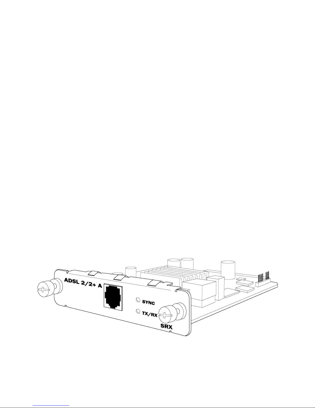
Chapter 2: SRX 210 Services Gateway Hardware Components and Specifications
Related Topics ■ SRX 210 Services Gateway T1/E1 Mini-Physical Interface Module on page 23
■ SRX 210 Services Gateway ADSL 2+ Mini-Physical Interface Module on page 29
■ Removing a Blank Mini-Physical Interface Module Faceplate from the SRX 210
Services Gateway on page 116
■ Removing a Mini-Physical Interface Module from the SRX 210 Services
Gateway on page 117
■ Installing a Mini-Physical Interface Module in the SRX 210 Services
Gateway on page 118
SRX 210 Services Gateway ADSL 2+ Mini-Physical Interface Module
This section contains the following topic:
■ ADSL 2+ Mini-Physical Interface Module on page 29
ADSL 2+ Mini-Physical Interface Module
The ADSL 2+ Mini-PIM provides a single physical interface to asymmetric digital
subscriber line (ADSL) network media types.
The ADSL Mini-PIM comprises of the following operational modes:
■ Annex A
■ Annex B
■ Annex M
Figure 7 on page 29 shows the ADSL 2+ Mini-PIM front panel.
Figure 7: ADSL 2+ Mini-PIM Front Panel
Supported Standards
The ADSL 2+ Mini-PIM supports the following standards:
SRX 210 Services Gateway ADSL 2+ Mini-Physical Interface Module ■ 29
Page 50

SRX 210 Services Gateway Hardware Guide
■ ANSI T1.413 Issue 2 (Annex A only)
■ ITU G.992.1 (G.dmt)
■ ITU G.992.3 (ADSL2)
■ ITU G.992.5 (ADSL2+)
Key Features
The ADSL 2+ Mini-PIM provides the following key features:
■ Automatic configuration of the ADSL line after negotiating with the DSLAM
■ Supports ADSL, ADSL2, and ADSL2+ protocols on the same interface card
■ Dying Gasp support
■ MLPPP over two ADSL cards
■ Asynchronous Transfer Mode (ATM) Adaptation Layer 5 (AAL5) encapsulation
■ Support of latency modes fast and interleave
■ Support for ATM AAL5 with CBR, VBR-nrt and UBR traffic types
■ Support for ten Permanent Virtual Circuits (PVCS)
LEDs
The ADSL 2+ Mini-PIM has two LEDs. Table 14 on page 30 shows the LED states.
Table 14: ADSL 2+ Mini-PIM LED States
DescriptionStatusColor IndicationLED
On steadilyGreenSYNC
Indicates that the ADSL interface is
trained
Indicates training is in progressBlinking
Indicates that the interface is idleOff
Indicates that traffic is passing throughBlinkingGreenTX/RX
Indicates that no traffic is passing throughOff
Specifications
Table 15 on page 31 describes the physical specifications of the ADSL 2+ Mini-PIM.
30 ■ SRX 210 Services Gateway ADSL 2+ Mini-Physical Interface Module
Page 51

Chapter 2: SRX 210 Services Gateway Hardware Components and Specifications
Table 15: ADSL 2+ Mini-PIM Physical Specifications
ValueDescription
Dimensions (H x W x L)
Supported operating modes
3.75” x 5.9” x 0.80”
(9.5 cm x 14.5 cm x 2.0 cm)
0.17 lb. (77.1g)Weight
RJ-11Connector type
Mini-PIMForm factor
32°F through 104°F (0°C through 40°C)Environmental operating temperature
–40°F through 158°F (–40°C through 70°C)Storage temperature
5% to 90% noncondensingRelative humidity
Network Interface Specifications
ValuesSpecifications
ADSL mode for ANNEX-A
Auto
■
ANSI-DMT(ANSI T1.413)
■
ITU-DMT(G.992.1)
■
ITU-DMT-BIS (G.992.3)
■
ADSL 2+(G.992.5)
■
ADSL mode for ANNEX-B
Auto
■
ITU-DMT(G.992.1)
■
ITU-DMT-BIS (G.992.3)
■
ADSL 2+(G.992.5)
■
ITU-ANNEXB-UR2
■
ITU-ANNEXB-NON-UR2
■
ETSI
■
ADSL mode for ANNEX-M
ITU-DMT-BIS (G.992.3)
■
ADSL 2+(G.992.5)
■
SRX 210 Services Gateway ADSL 2+ Mini-Physical Interface Module ■ 31
Page 52
SRX 210 Services Gateway Hardware Guide
ValuesSpecifications
Max Speed
Supports ATM CoS
Encapsulation supported
For ANSI DMT, 8 Mbps downstream and 896 Kbps Upstream
■
For G.992.1, 8 Mbps downstream and 1.2 Mbps Upstream
■
For G.992.3, 12 Mbps (AnnexA) or 10 Mbps (AnnexB) downstream and 1.2
■
Mbps Upstream
For G.992.5, 24 Mbps downstream and 1.2 Mbps Upstream
■
CBR
■
VBR
■
RTVBR
■
1500 bytesMTU
ATM-PVC
■
Ethernet-over-ATM
■
Loopback Diagnostics
■ OAM F4 far loopback test
■ OAM F4 near loopback test
■ OAM F5 far loopback test
■ OAM F5 near loopback test
Related Topics ■ SRX 210 Services Gateway T1/E1 Mini-Physical Interface Module on page 23
■ Removing a Blank Mini-Physical Interface Module Faceplate from the SRX 210
Services Gateway on page 116
■ Removing a Mini-Physical Interface Module from the SRX 210 Services
Gateway on page 117
■ Installing a Mini-Physical Interface Module in the SRX 210 Services
Gateway on page 118
■ Site Preparation Checklist for the SRX 210 Services Gateway on page 41
SRX 210 Services Gateway 3G ExpressCard
Wireless WAN access is becoming widely available and price-comparable to ISDN
and DSL. The SRX 210 services gateway provides support for a wireless interface as
a backup.
To facilitate wireless connectivity, the SRX 210 services gateway has a 3G port with
an ExpressCard USB interface.
32 ■ SRX 210 Services Gateway 3G ExpressCard
Page 53

Using the 3G ExpressCard
There are two types of 3G ExpressCards supported in the services gateway. The 3G
GSM/CDMA cards supports HSDPA (880EU) and EV-DO (597EU) modems. The
ExpressCard is plugged into the 3G ExpressCard slot and a wireless call is dialed to
the 3G Wireless service provider network, that acts as a gateway to the internet.
In order to use the 3G ExpressCard as a back up interface, you can make use of the
dialer feature available in the services gateway.
NOTE: Only Sierra 3G ExpressCards are supported.
Key Features
The 3G ExpressCard provides the following key features:
Chapter 2: SRX 210 Services Gateway Hardware Components and Specifications
■ On-board SIM — All GSM cards have an on-board SIM. The ISP populates this
SIM with the subscriber service parameters.
■ On-board NVRAM — The CDMA cards have an on-board NVRAM.
NOTE: Hot insertion and removal of the 3G ExpressCard is not supported.
■ Activation of new cards through the CLI — CDMA ExpressCards can be activated
from the JUNOS CLI.
■ Unlocking ExpressCards — GSM ExpressCards can be unlocked from the JUNOS
CLI. The GSM cards can be unlocked before activation.
NOTE: Locking / unlocking is supported only for GSM cards.
■ Interface support — The IP over PPP interface is supported across the USB
ExpressCard interface and from the network via the wireless link.
■ Dial-out support — The dialer interface is used to place calls and has multiple
features like dial-backup, dialer-watchlist and dialer-filter. In this case, the
ExpressCard functions as a subordinate.
NOTE: Dial-in is not supported on the 3G ExpressCard.
■ Card information availability— You can obtain information on the ExpressCard,
such as type, version, wireless status, and user profiles.
■ Security — The card supports a PIN lock to prevent unauthorized access and use
of the wireless account. You can enable or disable the SIM lock and unlock a
locked SIM using the request commands. You have the option to store the PIN
SRX 210 Services Gateway 3G ExpressCard ■ 33
Page 54

SRX 210 Services Gateway Hardware Guide
code you provide in the services gateway configuration information, so that the
SIM can be unlocked without user intervention on each reboot/reset on the box.
NOTE: Currently, PIN-protected SIMs are supported for all GSM cards.
Physical Parameters
The 3G ExpressCard has the following physical parameters:
■ Standard ExpressCard with 34 modules
■ Width — 34 mm
■ Thickness — 5 mm
■ Connector Pins — 26
■ Max power consumption — 1.3 W
■ Voltage supply — 3.3V (primary source) and 1.5V (secondary source)
Basic CLI Commands for 3G ExpressCard
Locking simcard
To enable locking in GSM sim cards, use the following command:
request modem wireless gsm sim-lock cl-0/0/8 enable pin <pin number>
NOTE: After enabling the sim lock, the 3G ExpressCard continues to be in unlock
state until it is reset either by power recycling the services gateway or by plugging
out and reinserting the card back in to the device and rebooting the device.
Unlocking sim card
To disable sim lock, i.e. to remove the security on GSM sim cards, use the following
command:
request modem wireless gsm sim-lock cl-0/0/8 disable pin <pin number>
Recovering sim card from puk state
While unlocking the sim if you continuously enter a wrong pin for 3 times, it will
enter puk state. To recover the sim back to normal, use the following command:
request modem wireless gsm sim-unblock puk <puk pin number>pin<New pin number>
NOTE: PUK needs to be obtained from the cellular service provider.
34 ■ SRX 210 Services Gateway 3G ExpressCard
Page 55

Chapter 2: SRX 210 Services Gateway Hardware Components and Specifications
Changing the PIN
To change the pin on the sim card, use the following command:
request modem wireless gsm change-pin cl-0/0/8 old-pin <current pin>new-pin <new
pin>
Checking the status of the 3G ExpressCard
To check the status of the 3G ExpressCard, use the following command:
show modem wireless interface cl-0/0/8
Related Topics Mini-Physical Interface Modules on the SRX 210 Services Gateway on page 22■
■ SRX 210 Services Gateway PoE Overview on page 35
SRX 210 Services Gateway PoE Overview
This section includes the following topics:
■ Introduction on page 35
■ PoE Classes and Power Ratings on page 36
Introduction
Power over Ethernet (PoE) is the implementation of the IEEE 802.3 AF standard,
allowing both data and electric power to pass over a copper Ethernet LAN cable.
The SRX 210 services gateway provides four PoE ports, which supply electric power
over the same ports that are used to connect network devices. PoE ports allow you
to plug in devices that require both network connectivity and electric power, such
as VOIP phones, wireless access points, and IP phones.
You can configure the gateway to act as power sourcing equipment to supply the
power to powered devices connected on the designated ports.
Table 16 on page 35 lists the SRX 210 services gateway PoE specifications.
Table 16: SRX 210 Services Gateway PoE Specifications
Supported standards
ValuesPower Management Schemes
IEEE 802.3 AF
■
Legacy (pre-standards)
■
Supported ports
PoE is supported on the following four ports:
ge-0/0/0 and ge-0/0/1
■
fe-0/0/2 and fe-0/0/3
■
50 wattsTotal PoE power sourcing capacity
SRX 210 Services Gateway PoE Overview ■ 35
Page 56
SRX 210 Services Gateway Hardware Guide
Table 16: SRX 210 Services Gateway PoE Specifications (continued)
ValuesPower Management Schemes
15.4 wattsPer port power limit
Power management modes
Static: power allocated for each interface can be
■
configured
Class: power allocation for interfaces is decided based
■
on the class of powered device connected
PoE Classes and Power Ratings
A powered device is classified based on the maximum power that it draws across
all input voltages and operational modes. When Class-based power management
mode is configured on the gateway, power is allocated taking into account the
maximum power ratings defined for the different classes of devices.
Table 17 on page 36 lists the classes and their power ratings as specified by the IEEE
802.3 AF standard.
Table 17: PoE Classes and Power Ratings on the SRX 210 Services Gateway
UsageClass
Maximum Power Levels Output from
PoE Port
15.4 WattsDefault0
4.0 WattsOptional1
7.0 WattsOptional2
15.4 WattsOptional3
Reserved4
All class-4 powered devices are treated
as class 0.
36 ■ SRX 210 Services Gateway PoE Overview
Page 57

Chapter 2: SRX 210 Services Gateway Hardware Components and Specifications
Related Topics ■ SRX 210 Services Gateway 3G ExpressCard on page 32
■ Site Preparation Checklist for the SRX 210 Services Gateway on page 41
SRX 210 Services Gateway PoE Overview ■ 37
Page 58

SRX 210 Services Gateway Hardware Guide
38 ■ SRX 210 Services Gateway PoE Overview
Page 59

Part 2
Setting Up the SRX 210 Services Gateway
■ Preparing the Site for the SRX 210 Services Gateway Installation on page 41
■ Installation Overview for the SRX 210 Services Gateway on page 49
■ Unpacking the SRX 210 Services Gateway on page 51
■ Preparing the SRX 210 Services Gateway for Installation on page 55
■ Installing the SRX 210 Services Gateway on page 59
■ Connecting the SRX 210 Services Gateway on page 67
■ Grounding and Powering On the SRX 210 Services Gateway on page 71
■ Establishing Basic Connectivity for the SRX 210 Services Gateway on page 77
■ Configuring Secure Web Access for the SRX 210 Services Gateway on page 103
Setting Up the SRX 210 Services Gateway ■ 39
Page 60

SRX 210 Services Gateway Hardware Guide
40 ■ Setting Up the SRX 210 Services Gateway
Page 61
Chapter 3
Preparing the Site for the SRX 210
Services Gateway Installation
This section provides a checklist to help you prepare your site. Before installing the
SRX 210 services gateway, read this section to make sure that your site has the
proper operating environment and equipment. This section provides information
about the following topics:
■ Site Preparation Checklist for the SRX 210 Services Gateway on page 41
■ General Site Guidelines for Installing the SRX 210 Services Gateway on page 43
■ SRX 210 Services Gateway Cabinet Requirements on page 44
■ SRX 210 Services Gateway Rack Requirements on page 45
■ Clearance Requirements for Airflow and Hardware Maintenance of the SRX 210
Services Gateway on page 46
■ SRX 210 Services Gateway Electrical and Power Requirements on page 47
Site Preparation Checklist for the SRX 210 Services Gateway
The checklist in Table 18 on page 41 summarizes the tasks you need to perform
when preparing a site for installing the SRX 210 services gateway.
Table 18: Site Preparation Checklist for the SRX 210 Services Gateway Installation
Environment
Verify that
environmental factors
such as temperature
and humidity do not
exceed device
tolerances.
Power
Measure distance
between external
power sources and
device installation site.
“SRX 210 Services Gateway
Environmental
Specifications” on page 155
“SRX 210 Services Gateway
Site Electrical Wiring
Guidelines” on page 157
Site Preparation Checklist for the SRX 210 Services Gateway ■ 41
NotesDatePerformed ByAdditional InformationItem or Task
Page 62

SRX 210 Services Gateway Hardware Guide
Table 18: Site Preparation Checklist for the SRX 210 Services Gateway Installation (continued)
NotesDatePerformed ByAdditional InformationItem or Task
Locate sites for
connection of system
grounding.
Calculate the power
consumption and
requirements.
Rack Installation
Verify that your rack
meets the minimum
requirements.
Plan rack location,
including required
space clearances.
Secure the rack to the
floor and building
structure.
Cabinet Installation
Verify that your
cabinet meets the
minimum
requirements.
Plan the cabinet
location, including
required space
clearances.
“SRX 210 Services Gateway
Power Specifications and
Requirements” on page 158
“SRX 210 Services Gateway
Rack
Requirements” on page 45
“SRX 210 Services Gateway
Cabinet
Requirements” on page 44
Wall Installation
Verify that the area
selected meets the
minimum
requirements.
Verify that you have
the required hardware
to proceed with the
installation.
Desktop Installation
Verify that the area
selected meets the
minimum
requirements.
“Preparing the SRX 210
Services Gateway for
Wall-Mount
Installation” on page 57
“Preparing the SRX 210
Services Gateway for
Desk-Mount
Installation” on page 56
42 ■ Site Preparation Checklist for the SRX 210 Services Gateway
Page 63

Chapter 3: Preparing the Site for the SRX 210 Services Gateway Installation
Table 18: Site Preparation Checklist for the SRX 210 Services Gateway Installation (continued)
NotesDatePerformed ByAdditional InformationItem or Task
Plan the installation
location, including
required space
clearances and airflow
requirements.
Cables
Acquire cables and
connectors.
Review the maximum
distance allowed for
each cable. Choose the
length of cable based
on the distance
between the hardware
components being
connected.
Plan the cable routing
and management.
“Interface Cable and Wire
Specifications for the SRX 210
Services Gateway” on page 161
Related Topics ■ SRX 210 Services Gateway Chassis on page 11
■ Installation Overview for the SRX 210 Services Gateway on page 49
■ General Site Guidelines for Installing the SRX 210 Services Gateway on page 43
■ SRX 210 Services Gateway Cabinet Requirements on page 44
■ SRX 210 Services Gateway Rack Requirements on page 45
■ Clearance Requirements for Airflow and Hardware Maintenance of the SRX 210
Services Gateway on page 46
General Site Guidelines for Installing the SRX 210 Services Gateway
Take the following precautions to help you plan an acceptable operating environment
for your SRX 210 services gateway and avoid environmentally caused equipment
failures:
■ For the cooling system to function properly, the airflow around the chassis must
be unrestricted. Allow sufficient clearance on both sides of the device and back
of the chassis where ventilation holed are located and adjacent equipment.
Ensure that there is adequate circulation in the installation location.
■ Follow the ESD procedures to avoid damaging equipment. Static discharge can
cause components to fail completely or intermittently over time. For more
information, see “SRX 210 Services Gateway General Safety Guidelines and
Warnings” on page 133.
General Site Guidelines for Installing the SRX 210 Services Gateway ■ 43
Page 64

SRX 210 Services Gateway Hardware Guide
■ Ensure that a blank Mini-PIM panel is installed in the empty slot to prevent any
interruption or reduction in the flow of air across internal components.
Related Topics ■ SRX 210 Services Gateway Chassis on page 11
■ SRX 210 Services Gateway Cabinet Requirements on page 44
■ SRX 210 Services Gateway Rack Requirements on page 45
■ Site Preparation Checklist for the SRX 210 Services Gateway on page 41
■ Clearance Requirements for Airflow and Hardware Maintenance of the SRX 210
Services Gateway on page 46
SRX 210 Services Gateway Cabinet Requirements
The SRX 210 services gateway can be installed in a standard 800 mm (31.5 in.) or
larger enclosed cabinet.
Cabinet Size and Clearance Requirements
You can install the SRX 210 services gateway in a 19 in. (48.3 cm) cabinet as defined
in Cabinets, Racks, Panels, and Associated Equipment (document number EIA-310–D)
published by the Electronics Industry Association (http://www.eia.org). You can mount
the SRX 210 services gateway horizontally in the cabinet.
NOTE: The holes for the mounting brackets chassis are spaced 1.25 in. (3.2 cm)
apart, measured from the center of the hole.
When selecting a cabinet, ensure that it meets the following specifications:
■ The cabinet is at least 1 U (1.75 in. or 4.5 cm) high and can accommodate the
device.
■ The outer edges of the mounting brackets extend the width of either chassis to
19 in. (48.2 cm), and the front of the chassis extends approximately 0.5 in. (1.27
cm) beyond the mounting brackets.
■ The minimum total clearance inside the cabinet is 30.7 in. (78 cm) between the
inside of the front door and the inside of the rear door.
NOTE: A cabinet larger than the minimum required provides better airflow and
reduces the chance of overheating.
44 ■ SRX 210 Services Gateway Cabinet Requirements
Page 65

Cabinet Airflow Requirements
When you mount the SRX 210 services gateway in a cabinet, you must ensure that
ventilation through the cabinet is sufficient to prevent overheating. Consider the
following requirements when planning for chassis cooling:
■ Ensure that the cool air supply you provide through the cabinet can adequately
dissipate the thermal output of the device.
■ Install the device as close as possible to the front of the cabinet so that the cable
management system clears the inside of the front door. Installing the chassis
close to the front of the cabinet maximizes the clearance in the rear of the cabinet
for critical airflow.
■ Route and dress all cables to minimize the blockage of airflow to and from the
chassis.
Related Topics ■ General Site Guidelines for Installing the SRX 210 Services Gateway on page 43
■ SRX 210 Services Gateway Rack Requirements on page 45
Chapter 3: Preparing the Site for the SRX 210 Services Gateway Installation
■ Site Preparation Checklist for the SRX 210 Services Gateway on page 41
■ Clearance Requirements for Airflow and Hardware Maintenance of the SRX 210
Services Gateway on page 46
SRX 210 Services Gateway Rack Requirements
The services gateway can be installed in a rack. Many types of racks are acceptable,
including front-mount racks and four-post (telco) racks.
Following are the rack requirements for your services gateway:
■ Rack Size and Strength
When installing the services gateway in a rack, you must ensure that the rack
complies with the following standard:
■ A 19 in. (45.6 cm) rack as defined in Cabinets, Racks, Panels, and Associated
Equipment (document number EIA-310-D) published by the Electronics
Industry Association (http://www.eia.org)
■ When selecting a rack, ensure that the physical characteristics of the rack
comply with the following specifications:
■ The outer edges of the mounting brackets extend the width of either
chassis to 19 in. (48.2 cm).
■ The front of the chassis extends approximately 0.5 in. (1.27 cm) beyond
the mounting ears.
SRX 210 Services Gateway Rack Requirements ■ 45
Page 66

SRX 210 Services Gateway Hardware Guide
NOTE: If you are mounting the gateway in a cabinet, be sure that ventilation is
sufficient to prevent overheating.
If a front-mount rack is used, we recommend supporting the back of the device with
a shelf or other structure
■ Spacing of Mounting Bracket and Flange Holes
The spacing of the mounting brackets and flange holes on the rack and device
mounting brackets are as follows:
■ The holes within each rack set are spaced at 1 U (1.75 in. or 4.5 cm). The
device can be mounted in any rack that provides holes or hole patterns
spaced at 1-U (1.75 in. or 4.5 cm) increments.
■ The mounting brackets and front-mount flanges used to attach the chassis
to a rack are designed to fasten to holes spaced at rack distances of 1 U (1.75
in).
■ The mounting holes in the mounting brackets provided with the device
chassis are spaced 1.25 in. (3.2 cm) apart, measured from the center of each
hole.
■ Connecting to the Building Structure
Always secure the rack in which you are installing the services gateway to the
structure of the building. If your geographical area is subject to earthquakes, bolt
the rack to the floor. For maximum stability, also secure the rack to ceiling
brackets.
Related Topics ■ General Site Guidelines for Installing the SRX 210 Services Gateway on page 43
■ SRX 210 Services Gateway Cabinet Requirements on page 44
■ Site Preparation Checklist for the SRX 210 Services Gateway on page 41
■ Clearance Requirements for Airflow and Hardware Maintenance of the SRX 210
Services Gateway on page 46
Clearance Requirements for Airflow and Hardware Maintenance of the SRX 210
Services Gateway
When planning the installation site for the SRX 210 services gateway, you need to
allow sufficient clearance around the rack.
When planning the installation site for the services gateway, consider the following:
■ For the cooling system to function properly, the airflow around the chassis must
be unrestricted.
46 ■ Clearance Requirements for Airflow and Hardware Maintenance of the SRX 210 Services Gateway
Page 67
Chapter 3: Preparing the Site for the SRX 210 Services Gateway Installation
■ For service personnel to remove and install hardware components, there must
be adequate space at the front and back of the device. Allow at least 24 in. (61
cm) both in front of and behind the device.
■ If you are mounting the device in a rack with other equipment, or if you are
placing it on the desktop near other equipment, ensure that the exhaust from
other equipment does not blow into the intake vents of the chassis.
Table 19 on page 47 provides information on the clearance requirements for
maintaining optimum airflow and the distances for facilitating easy maintenance of
the device.
Table 19: Clearance Requirements for the SRX 210 Services Gateway
Requirement for ClearanceRecommended ClearanceLocation
2.5 in. (6.35 cm)Front of the chassis
Space for service personnel to remove
and install hardware components
2.5 in. (6.35 cm)Rear of the chassis
Space for service personnel to remove
and install hardware components
or cabinet edge
2.5 in. (6.35 cm)Between front-mounting flange and rack
2.5 in. (6.35 cm)Between side of the chassis and any
non-heat-producing surface such as a
wall or cabinet side
2.5 in. (6.35 cm)Between side of the chassis and devices
that have fans or blowers
Space for cable management and
organization
Space for the cooling system to function
properly and to maintain unrestricted
airflow around the chassis
Space for the cooling system to function
properly and to maintain unrestricted
airflow around the chassis
Related Topics ■ SRX 210 Services Gateway Description on page 3
■ General Site Guidelines for Installing the SRX 210 Services Gateway on page 43
■ SRX 210 Services Gateway Cabinet Requirements on page 44
■ SRX 210 Services Gateway Rack Requirements on page 45
■ Site Preparation Checklist for the SRX 210 Services Gateway on page 41
SRX 210 Services Gateway Electrical and Power Requirements
The electrical and power requirements for the SRX 210 services gateway provide
information on the factors you must consider while planning the electrical wiring
and power availability at your site. These requirements cover the following areas:
■ Power specifications and requirements for the device
■ Electrical wiring guidelines for the device installation site
■ Power, connection, and power cord specifications for the device
■ Grounding guidelines and specifications for the device
SRX 210 Services Gateway Electrical and Power Requirements ■ 47
Page 68

SRX 210 Services Gateway Hardware Guide
Related Topics ■ SRX 210 Services Gateway Power Supply on page 22
■ Clearance Requirements for Airflow and Hardware Maintenance of the SRX 210
Services Gateway on page 46
■ SRX 210 Services Gateway Site Electrical Wiring Guidelines on page 157
■ Site Preparation Checklist for the SRX 210 Services Gateway on page 41
■ SRX 210 Services Gateway AC/DC Power, Connection, and Power Cord
Specifications
■ Interface Cable and Wire Specifications for the SRX 210 Services
Gateway on page 161
■ Installation Overview for the SRX 210 Services Gateway on page 49
48 ■ SRX 210 Services Gateway Electrical and Power Requirements
Page 69

Chapter 4
Installation Overview for the SRX 210
Services Gateway
This section includes the following topic:
■ Installation Overview for the SRX 210 Services Gateway on page 49
Installation Overview for the SRX 210 Services Gateway
After you have prepared your installation site, you are ready to unpack and install
the services gateway. It is important to proceed through the installation process in
the following order:
1. Review the safety guidelines explained in “SRX 210 Services Gateway General
Safety Guidelines and Warnings” on page 133.
2. Verify that you have prepared your site for the installation of the services gateway
using the checklist available in “Site Preparation Checklist for the SRX 210
Services Gateway” on page 41.
3. Follow the instructions in “Unpacking the SRX 210 Services Gateway” on page
51 to unpack the services gateway and verify that the parts are received.
4. Prepare the services gateway for installation as described in “Preparing the SRX
210 Services Gateway for Rack-Mount, Desk-Mount, and Wall-Mount
Installation” on page 55.
5. Install the services gateway as described in “SRX 210 Services Gateway
Installation” on page 60.
6. Connect cables to external devices as described in “Connecting Interface Cables
to the SRX 210 Services Gateway” on page 69.
7. Connect the grounding cable as described in “Grounding the SRX 210 Services
Gateway” on page 72.
8. Power on the services gateway as described in “Powering On and Powering Off
the SRX 210 Services Gateway” on page 73.
Installation Overview for the SRX 210 Services Gateway ■ 49
Page 70

SRX 210 Services Gateway Hardware Guide
50 ■ Installation Overview for the SRX 210 Services Gateway
Page 71

Chapter 5
Unpacking the SRX 210 Services Gateway
This section includes the following topics:
■ Required Tools and Parts for Unpacking the SRX 210 Services
Gateway on page 51
■ Unpacking the SRX 210 Services Gateway on page 51
■ Verifying Parts Received with the SRX 210 Services Gateway on page 52
Required Tools and Parts for Unpacking the SRX 210 Services Gateway
To unpack the SRX 210 services gateway, you need the following tools:
■ Phillips (+) screwdriver, number 2
■ 1/2 in. (13 mm) open-end or socket wrench to remove bracket bolts from the
shipping pallet
■ Blank panels to cover any slots not occupied by a component
Related Topics ■ Unpacking the SRX 210 Services Gateway on page 51
■ Verifying Parts Received with the SRX 210 Services Gateway on page 52
■ Preparing the SRX 210 Services Gateway for Rack-Mount Installation on page 56
■ Installation Overview for the SRX 210 Services Gateway on page 49
Unpacking the SRX 210 Services Gateway
The SRX 210 services gateway is shipped in a cardboard carton. The carton also
contains an accessory box and quick start instructions.
NOTE: The device is maximally protected inside the shipping carton. Do not unpack
it until you are ready to begin installation.
To unpack the SRX 210 services gateway:
1. Open the box in which the device is shipped.
2. Verify the parts received against the lists in Table 21 on page 52.
Required Tools and Parts for Unpacking the SRX 210 Services Gateway ■ 51
Page 72
SRX 210 Services Gateway Hardware Guide
3. Store the shipping box and packing material in case you need to return or move
the device at a later time.
Related Topics ■ Required Tools and Parts for Unpacking the SRX 210 Services
Gateway on page 51
■ Verifying Parts Received with the SRX 210 Services Gateway on page 52
■ Preparing the SRX 210 Services Gateway for Rack-Mount, Desk-Mount, and
Wall-Mount Installation on page 55
■ Installation Overview for the SRX 210 Services Gateway on page 49
Verifying Parts Received with the SRX 210 Services Gateway
The SRX 210 services gateway shipment package contains a packing list. Check the
parts in the shipment against the items on the packing list. The packing list specifies
the part numbers and descriptions of each part in your order.
If any part is missing, contact your Juniper Networks customer service representative.
A fully configured SRX 210 services gateway contains the chassis with installed
components, listed in Table 20 on page 52, and an accessory box, which contains
the parts listed in Table 21 on page 52.
NOTE: The parts shipped with your device can vary depending on the configuration
you ordered.
Table 20: Parts List for a Fully Configured SRX 210 Services Gateway
QuantityComponent
without Mini-PIM installed
Memory or 150W for PoE)
1Chassis, with 2xGE and 6xFE ports and a blank panel for slot
1Power supply adapter (60W for Low Memory and High
13-Prong Power Cord
1DB-9 to RJ-45 Adapter, Straight Through, 7 feet
Table 21: Accessory Parts List for the SRX 210 Services Gateway
52 ■ Verifying Parts Received with the SRX 210 Services Gateway
QuantityPart
1Juniper Networks Product Warranty
1End User License Agreement
1Getting Started Guide
Page 73
Chapter 5: Unpacking the SRX 210 Services Gateway
Table 21: Accessory Parts List for the SRX 210 Services Gateway (continued)
QuantityPart
1Security Products Safety Guide
1Juniper Compliance Form Letter
1Product Registration
1Tie Wrap
Related Topics ■ Required Tools and Parts for Unpacking the SRX 210 Services
Gateway on page 51
■ Unpacking the SRX 210 Services Gateway on page 51
■ Preparing the SRX 210 Services Gateway for Rack-Mount, Desk-Mount, and
Wall-Mount Installation on page 55
Verifying Parts Received with the SRX 210 Services Gateway ■ 53
Page 74

SRX 210 Services Gateway Hardware Guide
54 ■ Verifying Parts Received with the SRX 210 Services Gateway
Page 75

Chapter 6
Preparing the SRX 210 Services Gateway
for Installation
This section includes the following topics:
■ Preparing the SRX 210 Services Gateway for Rack-Mount, Desk-Mount, and
Wall-Mount Installation on page 55
■ Preparing the SRX 210 Services Gateway for Rack-Mount Installation on page 56
■ Preparing the SRX 210 Services Gateway for Desk-Mount Installation on page 56
■ Preparing the SRX 210 Services Gateway for Wall-Mount Installation on page 57
Preparing the SRX 210 Services Gateway for Rack-Mount, Desk-Mount, and
Wall-Mount Installation
You can mount an SRX 210 services gateway in a rack, on a desk, or on a wall. See
the topics below for more information:
■ Preparing the SRX 210 Services Gateway for Rack-Mount Installation on page 56
■ Preparing the SRX 210 Services Gateway for Desk-Mount Installation on page 56
■ Preparing the SRX 210 Services Gateway for Wall-Mount Installation on page 57
The separate, optional mounting kits are available for rack mounting, wall mounting,
and desk (vertical) mounting of the SRX 210 services gateway. Contact your Juniper
Networks customer service representative for more information.
Related Topics ■ Site Preparation Checklist for the SRX 210 Services Gateway on page 41
■ SRX 210 Services Gateway Rack Requirements on page 45
■ Clearance Requirements for Airflow and Hardware Maintenance of the SRX 210
Services Gateway on page 46
■ Unpacking the SRX 210 Services Gateway on page 51
■ Preparing the SRX 210 Services Gateway for Rack-Mount Installation on page 56
■ Preparing the SRX 210 Services Gateway for Desk-Mount Installation on page 56
■ Preparing the SRX 210 Services Gateway for Wall-Mount Installation on page 57
Preparing the SRX 210 Services Gateway for Rack-Mount, Desk-Mount, and Wall-Mount Installation ■ 55
Page 76

SRX 210 Services Gateway Hardware Guide
Preparing the SRX 210 Services Gateway for Rack-Mount Installation
You can mount an SRX 210 services gateway on four-post (telco) racks, enclosed
cabinets, and open-frame racks. Center mount racks are not supported.
Before mounting the SRX 210 services gateway in a rack:
■ Verify that the site meets the requirements described in “Site Preparation
Checklist for the SRX 210 Services Gateway” on page 41.
■ Verify that the racks or cabinets meet the specific requirements described in
“SRX 210 Services Gateway Rack Requirements” on page 45.
■ Place the rack or cabinet in its permanent location, allowing adequate clearance
for airflow and maintenance, and secure it to the building structure. For more
information, see “Clearance Requirements for Airflow and Hardware Maintenance
of the SRX 210 Services Gateway” on page 46.
■ Remove the services gateway chassis from the shipping carton. For unpacking
instructions, see “Unpacking the SRX 210 Services Gateway” on page 51.
■ Verify that you have the following parts available in your rack-mounting kit for
the SRX 210 services gateway:
■ Rack-mounting brackets
■ Screws
NOTE: The rack-mounting kit is not shipped with the device.
Related Topics ■ Site Preparation Checklist for the SRX 210 Services Gateway on page 41
■ SRX 210 Services Gateway Rack Requirements on page 45
■ Clearance Requirements for Airflow and Hardware Maintenance of the SRX 210
Services Gateway on page 46
■ Unpacking the SRX 210 Services Gateway on page 51
■ Preparing the SRX 210 Services Gateway for Rack-Mount, Desk-Mount, and
Wall-Mount Installation on page 55
■ Preparing the SRX 210 Services Gateway for Desk-Mount Installation on page 56
■ Preparing the SRX 210 Services Gateway for Wall-Mount Installation on page 57
Preparing the SRX 210 Services Gateway for Desk-Mount Installation
You can mount an SRX 210 services gateway on a desk or other level surface
horizontally or vertically. The four rubber feet attached to the chassis provide stability.
56 ■ Preparing the SRX 210 Services Gateway for Rack-Mount Installation
Page 77

Chapter 6: Preparing the SRX 210 Services Gateway for Installation
Before mounting an SRX 210 services gateway on a desk or other level surface:
■ Verify that the site meets the requirements described in “Site Preparation
Checklist for the SRX 210 Services Gateway” on page 41.
■ Place the desk in its permanent location, allowing adequate clearance for airflow
and maintenance, and secure it to the building structure.
■ Remove the services gateway chassis from the shipping carton. For unpacking
instructions, see “Unpacking the SRX 210 Services Gateway” on page 51.
■ If you are mounting the services gateway horizontally on a desk, ensure that the
chassis is attached with the rubber feet. If you are mounting the device vertically
on the desk, make sure that the following parts are available in your vertical
desk-mounting kit for the SRX 210 services gateway:
■ Vertical stand
■ Screws
NOTE: The vertical desk-mounting kit is not shipped with the device.
Related Topics ■ Site Preparation Checklist for the SRX 210 Services Gateway on page 41
■ SRX 210 Services Gateway Rack Requirements on page 45
■ Clearance Requirements for Airflow and Hardware Maintenance of the SRX 210
Services Gateway on page 46
■ Unpacking the SRX 210 Services Gateway on page 51
■ Preparing the SRX 210 Services Gateway for Rack-Mount, Desk-Mount, and
Wall-Mount Installation on page 55
■ Preparing the SRX 210 Services Gateway for Rack-Mount Installation on page 56
■ Preparing the SRX 210 Services Gateway for Wall-Mount Installation on page 57
Preparing the SRX 210 Services Gateway for Wall-Mount Installation
You can mount an SRX 210 services gateway on a wall. The four rubber feet attached
to the chassis provide stability.
Before mounting an SRX 210 services gateway on a wall:
■ Verify that the site meets the requirements described in “Site Preparation
Checklist for the SRX 210 Services Gateway” on page 41.
■ Remove the services gateway chassis from the shipping carton. For unpacking
instructions, see “Unpacking the SRX 210 Services Gateway” on page 51.
■ Verify that you have the following parts available in your wall-mounting kit for
the SRX 210 services gateway:
■ Wall-mounting brackets
■ Screws
Preparing the SRX 210 Services Gateway for Wall-Mount Installation ■ 57
Page 78

SRX 210 Services Gateway Hardware Guide
NOTE: The wall-mounting kit is not shipped with the device.
Related Topics ■ Site Preparation Checklist for the SRX 210 Services Gateway on page 41
■ SRX 210 Services Gateway Rack Requirements on page 45
■ Clearance Requirements for Airflow and Hardware Maintenance of the SRX 210
Services Gateway on page 46
■ Unpacking the SRX 210 Services Gateway on page 51
■ Preparing the SRX 210 Services Gateway for Rack-Mount, Desk-Mount, and
Wall-Mount Installation on page 55
■ Preparing the SRX 210 Services Gateway for Rack-Mount Installation on page 56
■ Preparing the SRX 210 Services Gateway for Desk-Mount Installation on page 56
58 ■ Preparing the SRX 210 Services Gateway for Wall-Mount Installation
Page 79

Chapter 7
Installing the SRX 210 Services Gateway
This section includes the following topics:
■ SRX 210 Services Gateway Safety Requirements, Warnings, and
Guidelines on page 59
■ Required Tools and Parts for Installing the SRX 210 Services Gateway on page 59
■ SRX 210 Services Gateway Installation on page 60
■ Removing and Installing Mini-Physical Interface Modules in the SRX 210 Services
Gateway on page 66
SRX 210 Services Gateway Safety Requirements, Warnings, and Guidelines
To avoid harm to yourself or the device as you install and maintain it, follow the
guidelines for working with and near electrical equipment, as well as the safety
procedures for working with devices. For a discussion of how to make the installation
site a safe environment and a list of safety warnings, see Related Topics. However,
providing an exhaustive set of guidelines for working with electrical equipment is
beyond the scope of this guide.
Related Topics ■ SRX 210 Services Gateway General Safety Guidelines and Warnings on page 133
■ SRX 210 Services Gateway Electrical Safety Guidelines and Warnings on page 150
■ Required Tools and Parts for Installing the SRX 210 Services Gateway on page 59
■ Preparing the SRX 210 Services Gateway for Wall-Mount Installation on page 57
■ General Site Guidelines for Installing the SRX 210 Services Gateway on page 43
Required Tools and Parts for Installing the SRX 210 Services Gateway
To install the device, you need the following tools and parts:
■ Phillips (+) screwdriver, number–2
■ Tie wrap
Related Topics SRX 210 Services Gateway Installation on page 60■
■ Removing and Installing Mini-Physical Interface Modules in the SRX 210 Services
Gateway on page 66
SRX 210 Services Gateway Safety Requirements, Warnings, and Guidelines ■ 59
Page 80

SRX 210 Services Gateway Hardware Guide
■ SRX 210 Services Gateway Safety Requirements, Warnings, and
Guidelines on page 59
SRX 210 Services Gateway Installation
You can install the SRX 210 services gateway in a rack, on a desk, or on a wall. The
device includes rubber feet for desk and wall mounting. The mounting brackets are
an optional accessory.
Install the device as appropriate for your site using one of the following procedures:
■ Installing the SRX 210 Services Gateway in a Rack on page 60
■ Installing the SRX 210 Services Gateway on a Desk on page 62
■ Installing the SRX 210 Services Gateway on a Wall on page 63
Installing the SRX 210 Services Gateway in a Rack
You can front-mount the SRX 210 services gateway in a rack. The mounting brackets
are an optional accessory. Many types of racks are acceptable, including four-post
(telco) racks, enclosed cabinets, and open-frame racks. For more information about
the type of rack or cabinet the SRX 210 services gateway can be installed into, see
“SRX 210 Services Gateway Rack Requirements” on page 45.
NOTE:
■ If you are installing multiple devices in one rack, install the lowest one first and
proceed upward in the rack.
■ Remove the rubber feet from the base of the chassis for rack installation.
To install the device in a rack:
60 ■ SRX 210 Services Gateway Installation
Page 81
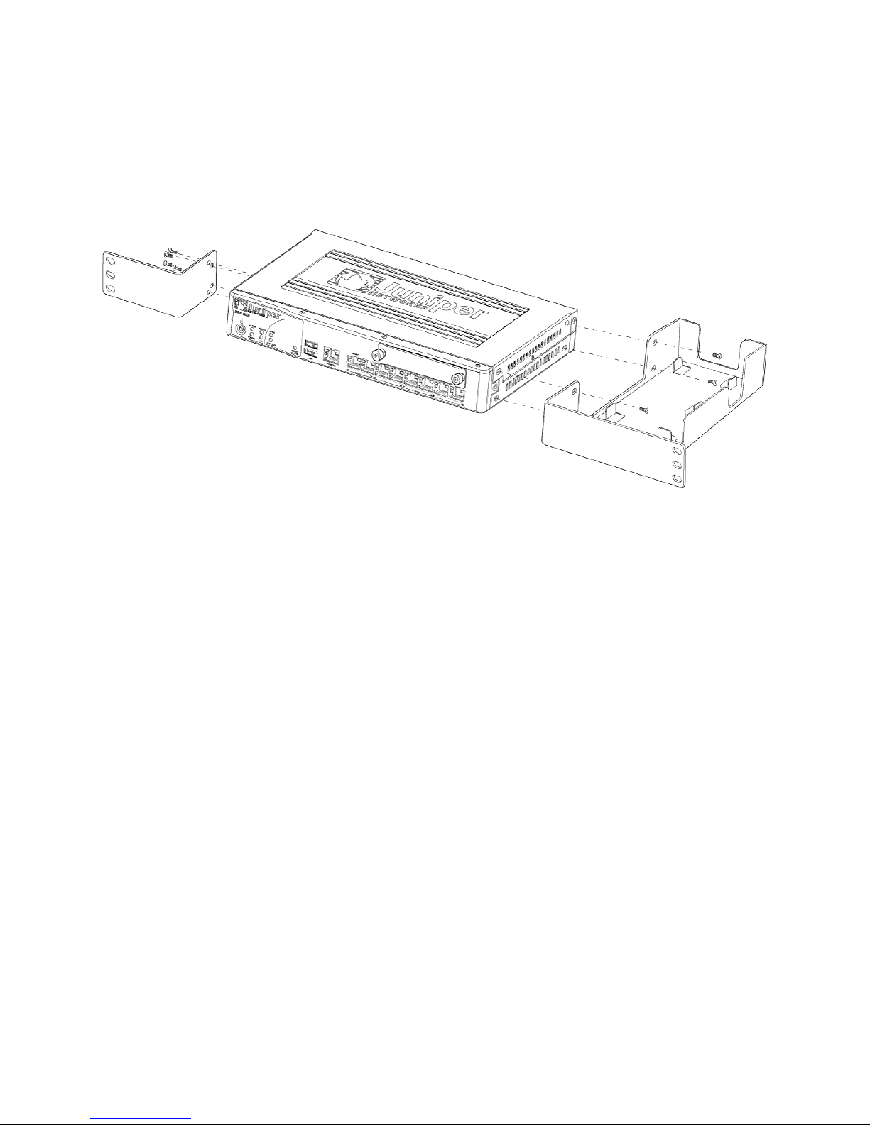
Chapter 7: Installing the SRX 210 Services Gateway
1. Position a mounting bracket on each side of the chassis as shown in
Figure 8 on page 61.
Figure 8: Installation of SRX 210 Services Gateway on a Rack
2. Use a number–2 phillips screwdriver to install the screws that secure the mounting
brackets to the chassis.
3. Have one person grasp the sides of the device, lift it, and position it in the rack.
4. Align the bottom hole in each mounting bracket with a hole in each rack rail as
shown in Figure 9 on page 62 making sure the chassis is level.
Installing the SRX 210 Services Gateway in a Rack ■ 61
Page 82
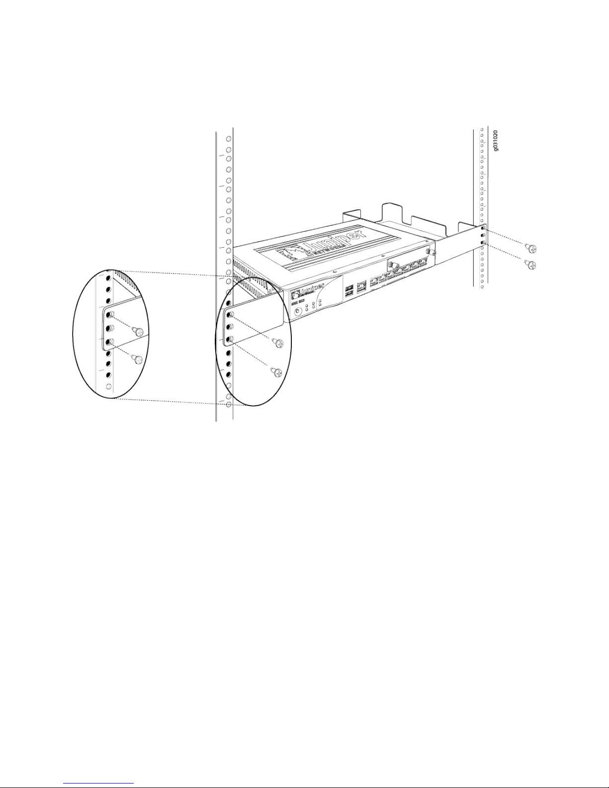
SRX 210 Services Gateway Hardware Guide
Figure 9: Hanging an SRX 210 Services Gateway in a Rack
5. Have a second person install a mounting screw into each of the two aligned
holes. Use a number–2 phillips screwdriver to tighten the screws.
6. Install the second screw in each mounting bracket.
7. Verify that the mounting screws on one side of the rack are aligned with the
mounting screws on the opposite side and that the device is level.
Installing the SRX 210 Services Gateway on a Desk
You can install the SRX 210 services gateway on a desk, table, or other level surface.
The device is shipped with the rubber feet attached. The rubber feet are necessary
to stabilize the device on the desk. You can install the device in a horizontal or vertical
position. The horizontal position is the standard installation position and does not
require the vertical installation kit. The vertical position requires the vertical installation
kit, which consists of a vertical installation stand with the rubber feet attached.
To install the device in a vertical position:
1. Attach the vertical stand to the right side of the chassis using the specified screws
as shown in Figure 10 on page 63.
62 ■ Installing the SRX 210 Services Gateway on a Desk
Page 83
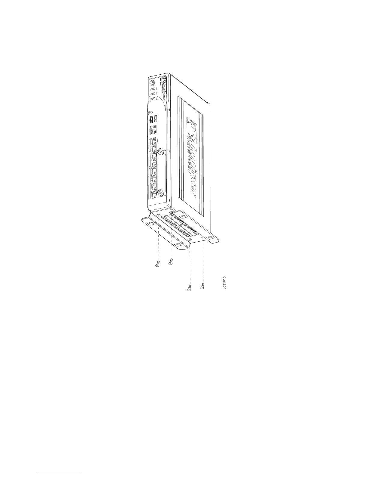
Chapter 7: Installing the SRX 210 Services Gateway
Figure 10: Vertical Installation of the SRX 210 Services Gateway on a Desk
2. Place the chassis on the desk with the stand side facing the desk.
Installing the SRX 210 Services Gateway on a Wall
You can install the SRX 210 services gateway on a wall. The device is shipped with
rubber feet in the accessory box. The rubber feet help stabilize the device on the
wall and enhance airflow. The mounting brackets are an optional accessory.
To install the device on a wall:
1. Turn the chassis upside down on a desk or work surface near where you intend
to operate the device.
2. Attach the provided rubber feet to the bottom of the chassis.
3. Position a mounting bracket on each side of the chassis as shown in
Figure 11 on page 64.
Installing the SRX 210 Services Gateway on a Wall ■ 63
Page 84
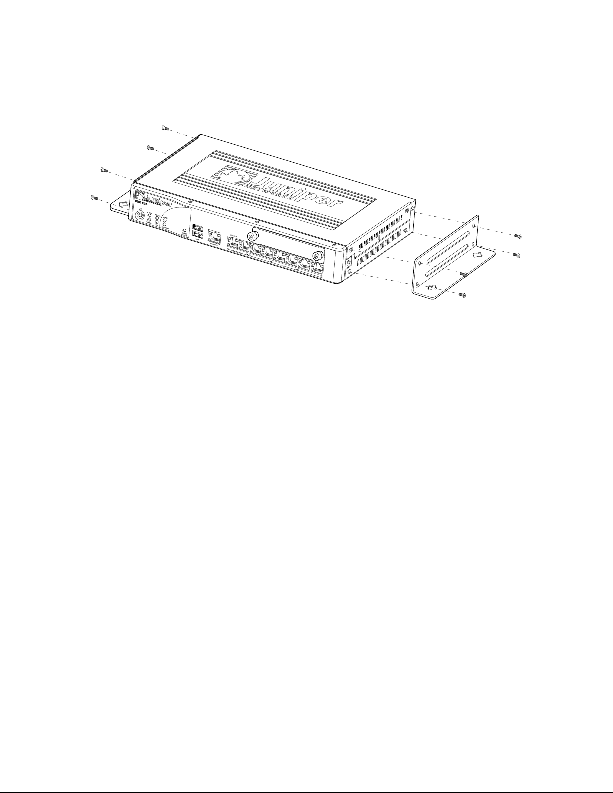
SRX 210 Services Gateway Hardware Guide
Figure 11: Installing the SRX 210 Services Gateway on a Wall
4. Use a number–2 phillips screwdriver to install the screws that secure the mounting
brackets to the chassis.
5. If you are using wall anchors to support the chassis, install two pairs of anchors
on the wall, spaced 19 in. (48.3 cm) apart.
6. Have one person grasp the sides of the device, lift it, and position it on the wall.
7. Have a second person install two pairs of mounting screws through the bracket
holes on either side of the device to secure it to the wall.
8. Verify that the mounting screws on one side are aligned with the mounting
screws on the opposite side and that the device is level (see
Figure 12 on page 65).
64 ■ Installing the SRX 210 Services Gateway on a Wall
Page 85
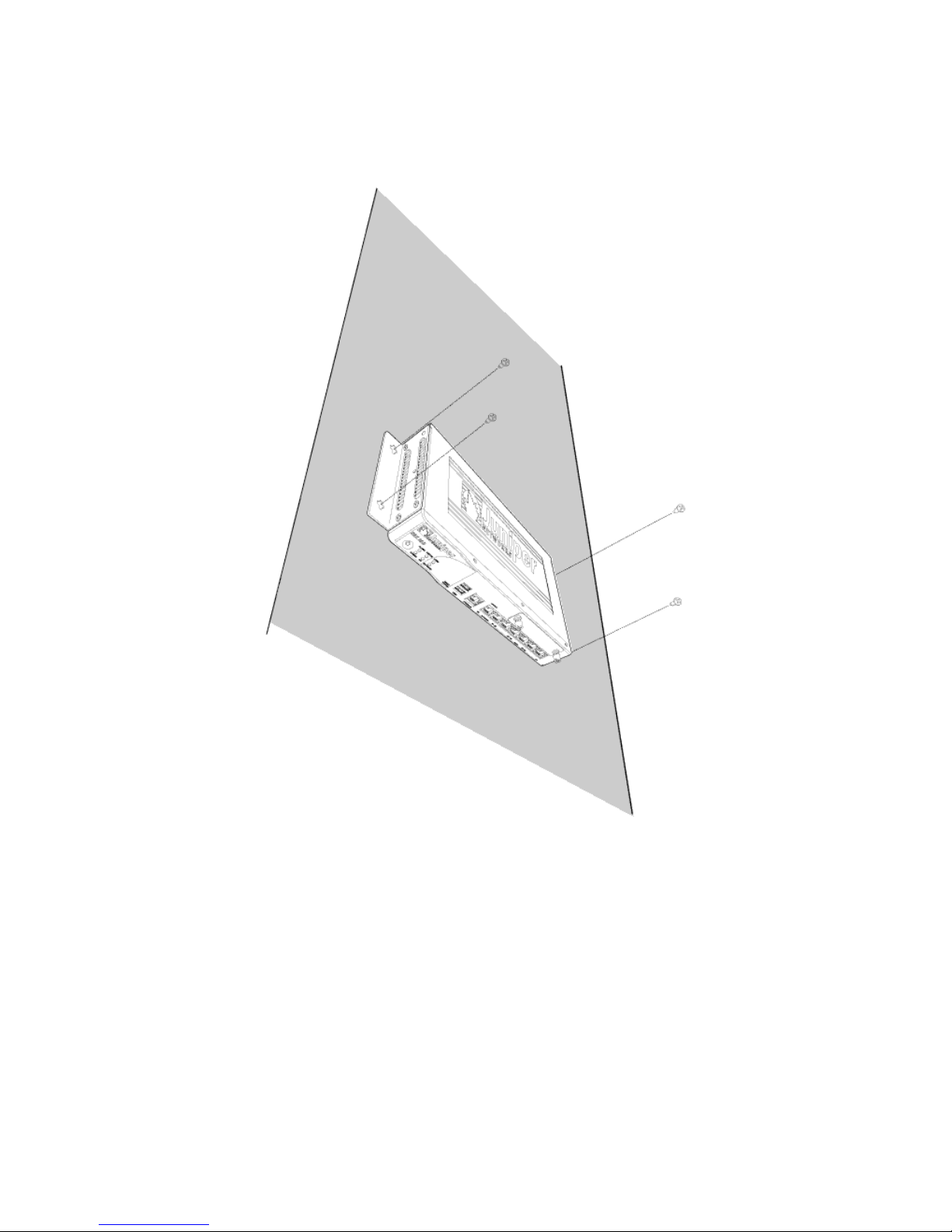
Chapter 7: Installing the SRX 210 Services Gateway
Figure 12: Hanging an SRX 210 Services Gateway on a Wall
Related Topics ■ Removing and Installing Mini-Physical Interface Modules in the SRX 210 Services
Gateway on page 66
■ Required Tools and Parts for Installing the SRX 210 Services Gateway on page 59
■ SRX 210 Services Gateway Safety Requirements, Warnings, and
Guidelines on page 59
■ Preparing the SRX 210 Services Gateway for Rack-Mount, Desk-Mount, and
Wall-Mount Installation on page 55
■ Preparing the SRX 210 Services Gateway for Rack-Mount Installation on page 56
■ Preparing the SRX 210 Services Gateway for Desk-Mount Installation on page 56
■ Preparing the SRX 210 Services Gateway for Wall-Mount Installation on page 57
Installing the SRX 210 Services Gateway on a Wall ■ 65
Page 86

SRX 210 Services Gateway Hardware Guide
Removing and Installing Mini-Physical Interface Modules in the SRX 210 Services
Gateway
Mini-Physical Interface Modules (Mini-PIMs) are circuit boards that you install in a
device. They enable you to easily add or change physical interfaces on a device.
The Mini-Physical Interface Module (Mini-PIM) slots are covered with a blank faceplate
to maintain proper airflow through the services gateway. Before installing the
Mini-PIM, you have to remove the faceplate.
See the following topics for installing the Mini-PIMs:
■ Removing a Blank Mini-Physical Interface Module Faceplate from the SRX 210
Services Gateway on page 116
■ Installing a Mini-Physical Interface Module in the SRX 210 Services
Gateway on page 118
■ Removing a Mini-Physical Interface Module from the SRX 210 Services
Gateway on page 117
Related Topics ■ Required Tools and Parts for Replacing a Mini-Physical Interface Module on the
SRX 210 Services Gateway on page 115
■ SRX 210 Services Gateway Installation Safety Guidelines and Warnings on page 138
■ SRX 210 Services Gateway Installation on page 60
■ Removing a Blank Mini-Physical Interface Module Faceplate from the SRX 210
Services Gateway on page 116
■ Installing a Mini-Physical Interface Module in the SRX 210 Services
Gateway on page 118
■ Removing a Mini-Physical Interface Module from the SRX 210 Services
Gateway on page 117
66 ■ Removing and Installing Mini-Physical Interface Modules in the SRX 210 Services Gateway
Page 87

Chapter 8
Connecting the SRX 210 Services
Gateway
This section includes the following topics:
■ Required Tools and Parts for Connecting the SRX 210 Services
Gateway on page 67
■ Connecting the SRX 210 Services Gateway to the Power Supply on page 67
■ Connecting Interface Cables to the SRX 210 Services Gateway on page 69
■ Organizing Interface Cables on the SRX 210 Services Gateway on page 69
Required Tools and Parts for Connecting the SRX 210 Services Gateway
To connect the services gateway, you need the following tools and parts:
■ Electrostatic discharge (ESD) grounding wrist strap
Related Topics Removing and Installing Mini-Physical Interface Modules in the SRX 210 Services
■
Gateway on page 66
■ Connecting the SRX 210 Services Gateway to the Power Supply on page 67
Connecting the SRX 210 Services Gateway to the Power Supply
To connect the device to the power supply:
1. Attach an electrostatic discharge (ESD) grounding strap to your bare wrist, and
connect the strap to the ESD point on the chassis.
2. Plug the DC connector end of the power cable into the power connector on the
back of the device (see Figure 13 on page 68).
3. Plug the AC adapter end of the power cable into an AC power outlet.
Required Tools and Parts for Connecting the SRX 210 Services Gateway ■ 67
Page 88
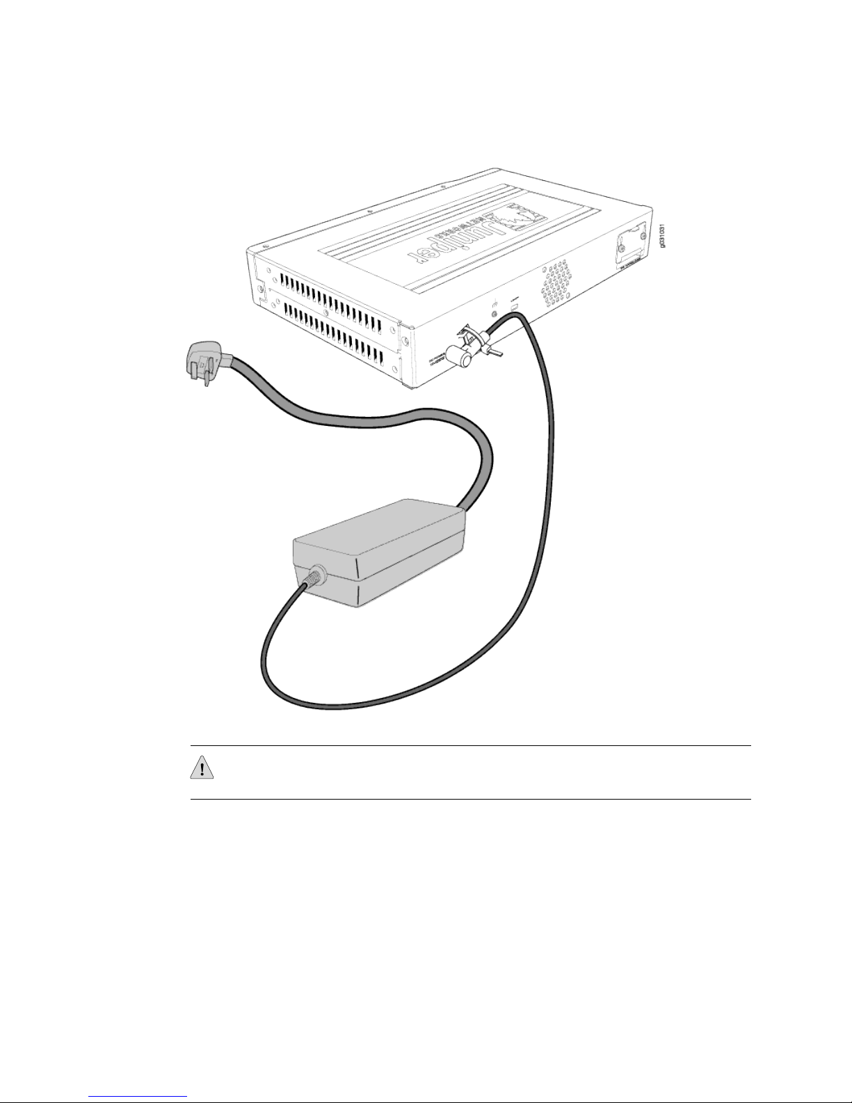
SRX 210 Services Gateway Hardware Guide
Figure 13: Connecting the Services Gateway to Power Supply
CAUTION: We recommend using a surge protector for the power connection.
Related Topics ■ Connecting Interface Cables to the SRX 210 Services Gateway on page 69
■ Organizing Interface Cables on the SRX 210 Services Gateway on page 69
■ Grounding the SRX 210 Services Gateway on page 72
■ Required Tools and Parts for Connecting the SRX 210 Services
Gateway on page 67
■ SRX 210 Services Gateway General Safety Guidelines and Warnings on page 133
68 ■ Connecting the SRX 210 Services Gateway to the Power Supply
Page 89

Chapter 8: Connecting the SRX 210 Services Gateway
Connecting Interface Cables to the SRX 210 Services Gateway
You connect the interfaces installed in the services gateway to various network media.
Each type of interface on a services gateway uses a particular medium to transmit
data. You must configure each network interface before it can operate on the device.
To connect the interface cable to the device:
1. Have ready a length of the type of cable used by the interface.
2. Insert the cable connector into the cable connector port on the interface faceplate.
NOTE: External devices can be attached to console, Ethernet, or Gigabit Ethernet
ports.
Related Topics Connecting the SRX 210 Services Gateway to the Power Supply on page 67■
■ Organizing Interface Cables on the SRX 210 Services Gateway on page 69
■ Interface Cable and Wire Specifications for the SRX 210 Services
Gateway on page 161
Organizing Interface Cables on the SRX 210 Services Gateway
Arrange network cables as follows to prevent them from dislodging or developing
stress points:
■ Secure cables so that they are not supporting their own weight as they hang to
the floor.
■ Place excess cable out of the way in neatly coiled loops.
■ Use fasteners to maintain the shape of cable loops.
Related Topics ■ Connecting Interface Cables to the SRX 210 Services Gateway on page 69
■ Required Tools and Parts for Grounding and Powering On the SRX 210 Services
Gateway on page 71
Connecting Interface Cables to the SRX 210 Services Gateway ■ 69
Page 90

SRX 210 Services Gateway Hardware Guide
70 ■ Organizing Interface Cables on the SRX 210 Services Gateway
Page 91

Chapter 9
Grounding and Powering On the SRX 210
Services Gateway
This section includes the following topics:
■ Required Tools and Parts for Grounding and Powering On the SRX 210 Services
Gateway on page 71
■ Grounding the SRX 210 Services Gateway on page 72
■ Powering On and Powering Off the SRX 210 Services Gateway on page 73
■ SRX 210 Services Gateway Autoinstallation Overview on page 74
Required Tools and Parts for Grounding and Powering On the SRX 210 Services
Gateway
To ground and to provide power to the device, you need the following tools and
parts:
■ Phillips (+) screwdrivers, numbers 1 and 2
Related Topics ■ Grounding the SRX 210 Services Gateway on page 72
■ Powering On and Powering Off the SRX 210 Services Gateway on page 73
■ Resetting the SRX 210 Services Gateway
■ Organizing Interface Cables on the SRX 210 Services Gateway on page 69
■ SRX 210 Services Gateway General Safety Guidelines and Warnings on page 133
Required Tools and Parts for Grounding and Powering On the SRX 210 Services Gateway ■ 71
Page 92
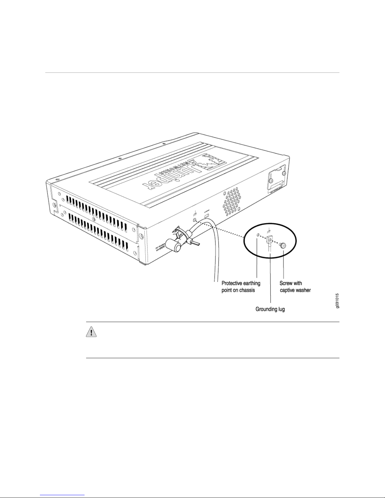
SRX 210 Services Gateway Hardware Guide
Grounding the SRX 210 Services Gateway
You ground the device by connecting a grounding cable to earth ground and then
attaching it to the chassis grounding points using two UNC 1/4-20 screws. You must
provide the grounding cables (the cable lugs are supplied with the services gateway).
Figure 14 on page 72 illustrates connecting agrounding cable to the services gateway.
Figure 14: Grounding the Services Gateway
CAUTION: Before device installation begins, a licensed electrician must attach a cable
lug to the grounding and power cables that you supply. A cable with an incorrectly
attached lug can damage the device (for example, by causing a short circuit).
To ground the device:
1. Attach an electrostatic discharge (ESD) grounding strap to your bare wrist, and
connect the strap to the ESD point on the chassis.
2. Ensure that all grounding surfaces are clean and brought to a bright finish before
grounding connections are made.
3. Connect the grounding cable to a proper earth ground.
4. Place the grounding cable lug over the grounding points on the upper rear of the
chassis. The left pair is sized for M6 bolts, and the right pair is sized for UNC
1/4-20 bolts.
72 ■ Grounding the SRX 210 Services Gateway
Page 93

Chapter 9: Grounding and Powering On the SRX 210 Services Gateway
5. Secure the grounding cable lug to the grounding points, first with the washers,
then with the screws.
6. Dress the grounding cable and verify that it does not touch or block access to
the services gateway components and that it does not drape where people could
trip on it.
Related Topics ■ Powering On and Powering Off the SRX 210 Services Gateway on page 73
■ Resetting the SRX 210 Services Gateway
■ Required Tools and Parts for Grounding and Powering On the SRX 210 Services
Gateway on page 71
■ SRX 210 Services Gateway General Safety Guidelines and Warnings on page 133
Powering On and Powering Off the SRX 210 Services Gateway
This topic describes the following procedures:
1. Powering On the SRX 210 Services Gateway on page 73
2. Powering Off the SRX 210 Services Gateway on page 73
Powering On the SRX 210 Services Gateway
To power on the services gateway, insert the DC plug into the DC jack of the device
and insert the AC adapter into the power supply faceplate. The device starts as the
power supply completes its startup sequence. The Power LED lights during startup
and remains on steadily when the device is operating normally.
Powering Off the SRX 210 Services Gateway
To power off the services gateway, you can shut it down in one of the following ways:
■ Graceful shutdown—Press and release the power button. The device begins
gracefully shutting down the operating system and then prints “press any key
to reboot.”
■ Immediate shutdown—Press the power button and hold it for ten seconds. The
device immediately shuts down. Press the button again once to power on the
device.
Powering On and Powering Off the SRX 210 Services Gateway ■ 73
Page 94

SRX 210 Services Gateway Hardware Guide
NOTE: To remove power completely from the device, unplug the AC power cord or
switch off the DC power source.
If the system is completely powered off when you turn on the power supply, the
device starts as the power supply completes its startup sequence. If the device finishes
starting and you need to power off the system again, first issue the CLI request system
halt command.
After a power supply is turned on, it can take up to 60 seconds for status
indicators—such as the Status LEDs on the power supply and the show chassis
command display—to indicate that the power supply is functioning normally. Ignore
error indicators that appear during the first 60 seconds.
For immediate restart, there is no hardware restart and the device is not powered
off. To power off the device, the command needs to be provided through the software.
The device software displays a message prompting you to remove the power cable.
When the power cable is removed, the device is completely powered off.
Related Topics Grounding the SRX 210 Services Gateway on page 72■
■ Resetting the SRX 210 Services Gateway
■ SRX 210 Services Gateway Front Panel on page 12
SRX 210 Services Gateway Autoinstallation Overview
The autoinstallation process begins any time a services gateway is powered on and
cannot locate a valid configuration file in the internal flash. Typically, a configuration
file is unavailable when a services gateway is powered on for the first time, or if the
configuration file is deleted from the internal flash. The autoinstallation feature
enables you to deploy multiple services gateways from a central location in the
network.
If you are setting up many devices, autoinstallation can help automate the
configuration process by loading configuration files onto new or existing devices
automatically over the network. You can use either the J-Web configuration editor
or CLI configuration editor to configure a device for autoinstallation. The J-Web
interface does not include Quick Configuration pages for autoinstallation
For the autoinstallation process to work, you must store one or more host-specific
or default configuration files on a configuration server in the network and have a
service available—typically Dynamic Host Configuration Protocol (DHCP)—to assign
an IP address to the services gateway.
Autoinstallation takes place automatically when you connect an Ethernet port on a
new services gateway to the network and power on the device. To simplify the
process, you can explicitly enable autoinstallation on a device and specify a
configuration server, an autoinstallation interface, and a protocol for IP address
acquisition.
74 ■ SRX 210 Services Gateway Autoinstallation Overview
Page 95

Chapter 9: Grounding and Powering On the SRX 210 Services Gateway
NOTE: The autoinstallation is enabled on all ports of the services gateway. If you do
not want to use the autoinstallation, you must delete the autoinstallation using CLI
configuration editor.
For more information about configuring autoinstallation, see Administration Guide
for J-series Services Routers and SRX-series Services Gateways
Related Topics ■ Powering the SRX 210 Services Gateway On and Off
■ SRX 210 Services Gateway Basic Connectivity Overview on page 78
SRX 210 Services Gateway Autoinstallation Overview ■ 75
Page 96

SRX 210 Services Gateway Hardware Guide
76 ■ SRX 210 Services Gateway Autoinstallation Overview
Page 97

Chapter 10
Establishing Basic Connectivity for the
SRX 210 Services Gateway
This section includes the following topics:
■ SRX 210 Services Gateway Basic Connectivity on page 77
■ Connecting to an SRX 210 Services Gateway on page 86
■ Configuring Basic Settings for the SRX 210 Services Gateway with J-Web Quick
Configuration on page 93
■ Configuring Basic Settings for the SRX 210 Services Gateway with a Configuration
Editor on page 96
■ Displaying Basic Connectivity Configurations for the SRX 210 Services
Gateway on page 99
■ Configuring the SRX 210 Services Gateway Mini-Physical Interface
Modules on page 100
SRX 210 Services Gateway Basic Connectivity
This section includes the following topics on connecting the SRX 210 services gateway
to the network and establishing basic connectivity:
■ SRX 210 Services Gateway Basic Connectivity Overview on page 78
■ Device Identification for the SRX 210 Services Gateway on page 79
■ Root Password for the SRX 210 Services Gateway on page 79
■ Time Zone and System Time for the SRX 210 Services Gateway on page 80
■ Network Settings for the SRX 210 Services Gateway on page 80
■ Default Gateway for the SRX 210 Services Gateway on page 82
■ Backup Device for the SRX 210 Services Gateway on page 83
■ Loopback Address for the SRX 210 Services Gateway on page 83
■ Built-In Ethernet Port for the SRX 210 Services Gateway on page 84
■ Management Access for the SRX 210 Services Gateway on page 85
SRX 210 Services Gateway Basic Connectivity ■ 77
Page 98

SRX 210 Services Gateway Hardware Guide
SRX 210 Services Gateway Basic Connectivity Overview
The JUNOS software is preinstalled on the services gateway. When the device is
powered on, it is ready to be configured.
If you are setting up a services gateway for the first time, you can use either J-Web
Quick Configuration or a configuration editor to configure basic connectivity.
If you are setting up many s, autoinstallation can help automate the configuration
process.
Before you configure the services gateway for the first time, you should complete
the following prerequisite tasks:
Table 22: Services Gateway Prerequisite Tasks
DetailsTask
Gather the information on:
If you are performing the initial configuration with the J-Web
interface, gather the following equipment:
If you are performing the initial configuration with the CLI,
gather the following equipment:
Device identification
■
Hostname for the device on the network
■
Domain that the device belongs to on the network
■
Password for the root user
■
Time zone information
■
System time and zone for services gateway location
■
IP address of a Network Time Protocol (NTP) server,
■
if NTP is used to set the time on the services
gateway
Network settings for the services gateway:
■
IP address of a DNS server
■
List of domains that can be appended to hostnames
■
for DNS resolution
IP address of the default gateway
■
IP address to be used for the loopback interface.
■
IP address of the built-in Ethernet port that you will use
■
for management purposes. For example, use the
ge-0/0/0 interface
Management device, such as a laptop, with an Ethernet
■
port
Ethernet cable (provided)
■
Management device, such as a PC or laptop, with a serial
■
port and an asynchronous terminal application (such as
Microsoft Windows HyperTerminal)
Ethernet cable (provided)
■
For a remote connection, gather the following equipment:
■
Two dial-up modems
■
An adapter appropriate for your modem (not
■
provided)
78 ■ SRX 210 Services Gateway Basic Connectivity Overview
Page 99

Chapter 10: Establishing Basic Connectivity for the SRX 210 Services Gateway
Related Topics ■ SRX 210 Services Gateway Autoinstallation Overview
■ Device Identification for the SRX 210 Services Gateway on page 79
■ Root Password for the SRX 210 Services Gateway on page 79
■ Time Zone and System Time for the SRX 210 Services Gateway on page 80
■ Network Settings for the SRX 210 Services Gateway on page 80
■ Default Gateway for the SRX 210 Services Gateway on page 82
■ Backup Device for the SRX 210 Services Gateway on page 83
■ Loopback Address for the SRX 210 Services Gateway on page 83
■ Built-In Ethernet Port for the SRX 210 Services Gateway on page 84
■ Management Access for the SRX 210 Services Gateway on page 85
■ Connecting an SRX 210 Services Gateway to the J-Web Interface on page 86
■ Connecting an SRX 210 Services Gateway to the CLI Locally on page 88
■ Connecting an SRX 210 Services Gateway to the CLI Remotely on page 90
Device Identification for the SRX 210 Services Gateway
The domain name defines the network or subnetwork to which the SRX 210 services
gateway belongs. The hostname refers to the specific machine, while the domain
name is shared among all devices in a given network. Together the hostname and
domain name identify the device in the network.
Related Topics SRX 210 Services Gateway Basic Connectivity Overview on page 78■
■ Root Password for the SRX 210 Services Gateway on page 79
■ Time Zone and System Time for the SRX 210 Services Gateway on page 80
Root Password for the SRX 210 Services Gateway
The root user has complete privileges to configure the SRX 210 services gateway
and manage files in the device's file system. Initially, the root password is not defined
on the device. To ensure basic security, you must define the root password during
initial configuration. If a root password is not defined, you cannot commit
configuration settings on the device.
NOTE: If you use a plaintext password, the device displays the password as an
encrypted string so that users viewing the configuration cannot see it.
The root password must meet the following conditions:
■ Must be at least six characters long.
■ Most character classes can be included in a password (alphabetic, numeric, and
special characters), except control characters.
Device Identification for the SRX 210 Services Gateway ■ 79
Page 100

SRX 210 Services Gateway Hardware Guide
■ Must contain at least one change of case or character class.
For Common Criteria environments only, the password must be between 10 and 20
characters long and must include at least 3 of the 5 character classes (uppercase
letters, lowercase letters, punctuation marks, numbers, and other special characters).
Control characters are not recommended. For more information, see the Secure
Configuration Guide for Common Criteria and JUNOS-FIPS.
Related Topics SRX 210 Services Gateway Basic Connectivity Overview on page 78■
■ Device Identification for the SRX 210 Services Gateway on page 79
■ Time Zone and System Time for the SRX 210 Services Gateway on page 80
Time Zone and System Time for the SRX 210 Services Gateway
You define the time zone for the location where you plan to operate the SRX 210
services gateway by using a designation that consists of the following information
for the location:
■ Name of the continent or ocean—For example, America or Pacific
■ Name of the major city or other geographic feature in the time zone—For
example, Boston or Azores
A Network Time Protocol (NTP) server provides accurate time across a network. The
device synchronizes the system time with the NTP server and periodically accesses
the NTP server to maintain the correct time.
The time zone and system time must be accurate so that the device schedules events
and operations as expected.
For Common Criteria compliance, you must configure NTP to provide accurate
timestamps for system log messages. For more information, see the Secure
Configuration Guide for Common Criteria and JUNOS-FIPS.
Related Topics SRX 210 Services Gateway Basic Connectivity Overview on page 78■
■ Root Password for the SRX 210 Services Gateway on page 79
■ Network Settings for the SRX 210 Services Gateway on page 80
Network Settings for the SRX 210 Services Gateway
Table 23 on page 81 provides the information on basic connectivity settings:
80 ■ Time Zone and System Time for the SRX 210 Services Gateway
 Loading...