

Page 1
V
Getting Started Guide
SRX210 Services Gateway
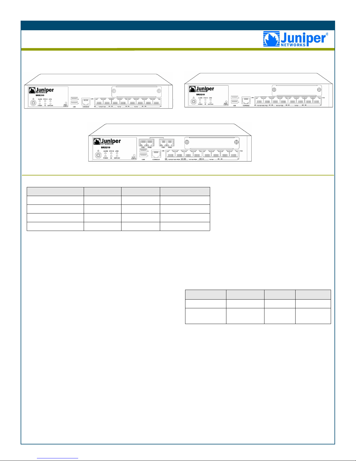
Use the instructions in this guide to help you connect the SRX210 Services Gateway to your network. For details, see the
SRX210 Services Gateway Hardware Guide at http://www.juniper.net/techpubs/a057.html.
SRX210 Services Gateway (Low Memory and High Memory)
SRX210 Services Gateway with Integrated Convergence Services
SRX210 Services Gateway (Power over Ethernet)
The following four types of SRX210 Services Gateways are available:
Device DDR Memory PoE Voice Support
SRX210B 512 MB No No
SRX210H 1 GB No No
SRX210H-POE 1 GB Yes No
SRX210-P-MGW 1 GB Yes Yes
Note: On the SRX210H-PoE and SRX210-P-MGW
models, Power over Ethernet (PoE) of 50 watts is
supported across 4 ports (ge-0/0/0, ge-0/0/1, fe-0/0/2,
and fe-0/0/3).
PART 1 - CONNECTING AND CONFIGURING THE DEVICE
Use the instructions below to connect and set up the SRX210 Services Gateway to protect your network. Refer to the LEDs on the
front panel of the device to help you determine the status of the device.
Step 1
Connect the power cable to the device and a power source. We
recommend using a surge protector. Note the following indications:
• Power LED (green): The device is receiving power.
• Status LED (green): The device is operating normally.
Note: You must allow the device between 5 and 7 minutes to boot up after
you have powered it on. Wait until the Status LED is solid green before
proceeding to the next step.
Step 2
Connect the management device to the services gateway using either of
the following methods:
• Connect an Ethernet cable from one of the following ports to the
Ethernet port on the management device (workstation or laptop):
•ge-0/0/1
• fe-0/0/2 through fe-0/0/7
We recommend this connection method. If you are using this
method to connect, proceed with Step 3.
• Connect an RJ-45 cable from the console port to the supplied DB-9
adapter, which then connects to the serial port on the management
device. (Serial port settings: 9600 8-N-1-N).
If you are using this method to connect, proceed with the CLI
configuration instructions available in the Quickstart Guide for
Branch SRX Series Services Gateways at
http://www.juniper.net/us/en/local/pdf/app-notes/3500153-en.pdf.
Step 3
Ensure that the management device acquires an IP address on the
192.168.1/24 subnetwork (other than 192.168.1.1) from the device.
The interfaces have following factory-default settings:
Interface Security Zone DHCP State IP Address
ge-0/0/0 untrust client unassigned
ge-0/0/1 and fe-0/
0/2 to fe-0/0/7
Notes:
• The services gateway functions as a DHCP server and will assign an IP
address to the management device.
• If an IP address is not assigned to the management device, manually
configure an IP address in the 192.168.1.0/24 subnetwork. Do not
assign the 192.168.1.1 IP address to the management device, as this IP
address is assigned to the device. By default, the DHCP server is
enabled on the L3 VLAN interface, (IRB) vlan.0 (ge-0/0/1 and fe-0/0/2
to fe-0/0/7), which is configured with an IP address of 192.168.1.1/24.
• When an SRX210 Series Services Gateway is powered on for the first
time, it boots using the factory default configuration.
trust server 192.168.1.1/24
Step 4
Access the J-Web interface:
1. Launch a Web browser from the management device.
2. Enter 192.168.1.1 in the URL address field.
3. Specify the default user name as root. Do not enter any value in the
Password field.
Page 2
Getting Started Guide
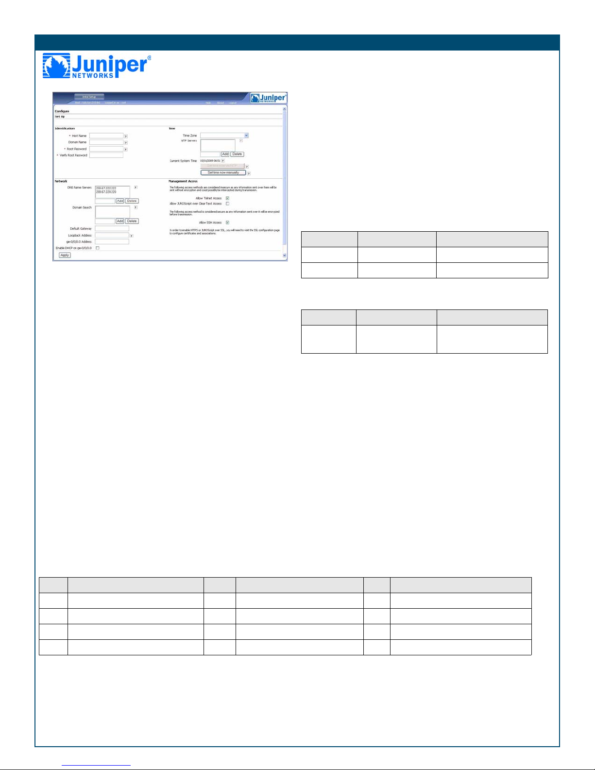
4. Press Enter. The J-Web Initial Setup page is displayed.
from the VLAN.
Note: To remove the interfaces from VLAN:
a. In the J-Web interface, under the Configure tab, navigate to Switching
> VLAN.
b. Under VLAN name, select the VLAN and click Edit to select and remove
the interfaces from VLAN.
Note: By default, Ethernet switching is enabled on the ge-0/0/1 and fe-0/0/2
to fe-0/0/7 ports.
7. Click OK to save the changes and click Commit to apply the
changes. The configured IP address is included in the Address
Prefix column.
Step 8
Security policies have the following factory-default settings:
Source Zone Destination Zone Policy Action
trust untrust permit
Step 5
Configure the basic settings such as Host Name, Domain Name, and
Root Password for your services gateway.
Important: Ensure that you have configured the root password before you
apply the configuration.
Note: All fields marked with an asterisk (*) are mandatory.
Step 6
Click Apply to apply the configuration.
Step 7
Configure an interface as follows:
1. In the J-Web interface, select the Configure tab.
2. Under the Interface Name column, click on the interface you want to
configure.
3. Click the existing logical interface.
4. Make sure that Enable Ethernet Switching is unchecked.
5. Under IPv4 Addresses and Prefixes, click Add.
6. In the IPv4 Address and Prefix field, enter an IP address and a
subnet mask.
Note: You can either configure an IPV4 address to a physical interface or
you can make it part of the L2 VLAN. By default, all ports except the ge-0/0/0
port are in the L2 VLAN.
Note: Before configuring the IPV4 address, the interface should be removed
untrust trust deny
Note: By default, the security policy is Deny-all.
The NAT rule has the following factory-default setting:
Source Zone Destination Zone Policy Action
trust untrust Source NAT to untrust zone
interface IP address
By default, ge-0/0/1 and fe-0/0/2 to fe-0/0/7 are in the trust zone and
Note:
ge-0/0/0 is in the untrust zone
To add an interface to a specific, preconfigured zone:
1. In the J-Web interface under the Configure tab, navigate to Security
> Zones.
2. Under Zones Lists, click Add and enter a name for the zone in the
Zone Name field.
3. Under Interfaces In This Zone, add an interface to a specific zone.
4. Click OK to save changes and click Commit to apply the changes.
.
Step 9
Modify the security policy as follows:
1. In the J-Web interface, under the Configure tab, navigate to
Security > Policy.
2. Select the zone direction. For more information on configuring
zones, see the JUNOS Security Configuration Guide.
PART 2 - CONNECTING AND CONFIGURING THE MEDIA GATEWAY
Use the instructions below to configure voice support on the services gateway and get started using your device to place
and receive calls.
Step Task Step Task Step Task
1 Connect the FXO and FXS ports. 5 Configure the analog station. 9 Create the dial plan.
2 Access the J-Web interface. 6 Configure the peer call server. 10 Configure the media gateway.
3 Configure the class of restriction. 7 Configure the trunk. 11 Configure the survivable call server.
4 Configure the SIP station. 8 Configure trunk groups.
Step 1
Connect the FXO and FXS ports:
1. Connect an FXS port (FXS1 or FXS2) on the device to an analog
device such as a telephone, fax, or modem through an RJ-11 cable.
2. Connect an FXO port (FXO1 or FXO2) on the device to the central
office (CO) switches or to a station port on a PSTN through an RJ11 cable.
3. Connect an Ethernet cable from any of the PoE ports (ge-0/0/0, ge0/0/1, fe-0/0/2, fe-0/0/3) to the VoIP phone.
Step 2
Access the J-Web interface:
1. Launch a Web browser from the management device.
Page 3

2. Log on using the credentials you set during the initial
configuration described in Part 1.
3. The J-Web Dashboard page is displayed.
Step 3
Configure the class of restriction to define the policy dedicated to
specifying call type permissions:
1. Select Configure > Convergence Services > Station > Class of
Restriction. The Class of Restriction Configuration page is
displayed.
2. Click Add to create a new class of restriction. The New Class of
Restriction page is displayed.
3. Enter the name in the Class of Restriction field.
4. Click Add to add a new policy to the class of restriction you are
creating. The New Policy Configuration page is displayed.
5. Perform the following actions:
Field Action
Policy Name Specify a name for the policy.
Available Call
Types
Select the call types applicable to your
setup.
Permissions Set permissions (allow or deny) on the
selected call types.
Note: By default, only intra-branch calls and emergency calls are allowed.
Step 4
Configure the SIP station:
Note: For initial configuration of the device, you do not need to configure
the station templates. You can use the default values.
1. Select Configure > Convergence Services > Station.
The Station Configuration Page is displayed.
2. Click Add to add the new station.
3. Perform the following mandatory basic actions:
Field Action
Name Specify a name for the station.
Extension Enter the extension number of the station.
Class of Restriction Select the al rea dy confi gured class of
restriction.
Template Name Select the already defined station
template.
You can configure the analog templates to be similar so that they can
share a common configuration
Step 5
Configure the analog station:
1. Select Configure > Convergence Services > Station.
The Station Configuration page is displayed.
2. Click Add to add the new station.
3. Perform the following mandatory basic actions:
Field Action
Name Specify a name for the station.
Extension Enter the extension number of the station.
Getting Started Guide
Field Action
Class of Restriction Select the already configured class of
restriction.
Template Name Select the already defined station template.
TDM Interface Specify the type of TDM interface to be
configured (FXO, FXS, or T1).
Note: You can configure the individual SIP stations similarly so that they
can share a common configuration.
Step 6
Configure the peer call server that provides call routing and call
handling services for the device:
1. Select Configure > Convergence Services > Call Server.
The Peer Call Server Configuration page is displayed.
2. Perform the following mandatory basic actions:
Field Action
Name Specify the name for the peer call server.
PSTN Access
Number
Address Type Select the address type as either fqdn or
FQDN Enter the fully qualified domain name.
IP Address Enter the IP address of the peer call
Note: For the device to authenticate itself with the peer call server, you
might need to provide the device user ID and password details as provided
by the peer call server’s administrator.
Note: You can accept the default values in the Port (5060) and Transport
(UDP) fields.
Note: For initial configuration of the device, you do not need to specify the
codec. The default set of codecs is used. By default, codecs are specified in
the following order:
711-µ, G711-A, G729AB
Step 7
Configure a trunk for a PSTN time-division multiplexing (TDM)
interface to be used by the device or the survivable call server to route
calls to the destination.
1. Select Configure > Convergence Services > Gateway > Trunks.
The New Trunk Configuration page is displayed.
2. Perform the following actions:
Field Your Action
Trunk Name Enter a name for the trunk.
Trunk Type Select the trunk type (FXO, FXS, or T1).
TDM Interface Select the type of TDM interface to be
Specify the external PSTN number for the
survivable call server to use if it must
contact the PSTN directly.
ipv4-address.
server.
configured (FXO, FXS, or T1) for routing
certain types of calls.
Page 4
Getting Started Guide
Step 8
Configure the trunk groups. A trunk group comprises multiple trunks
specified in the order of precedence in which they must be selected to
route a call.
1. Select Configure > Convergence Services > Gateway > Trunk
Groups. The Trunk Group Configuration page is displayed.
2. Click Add to create a new trunk group.
3. Perform the following mandatory actions:
Field Action
Name Specify a name for the trunk group.
Available Trunks Select the trunks applicable to your setup.
Step 9
Create the dial plan to enable the peer call server to route outbound calls
placed from SIP telephones / analog stations at the branch to its PSTN:
1. Select Configure > Convergence Services > Dia l Plan > Dial
Plan. The Dial Plan Configuration page is displayed.
2. Click Add to create a new dial plan. The New Dial Plan
Configuration page is displayed.
3. Enter a name in the Dial Plan Name field and click Add. The New
Route Pattern Configuration page opens.
4. Perform the following mandatory basic actions:
Field Action
Route Pattern Specify the route pattern name.
Call type Select the call type. The default is trunk-call.
Trunk-groups Select the preconfigured trunk groups to
include in the route pattern.
Note: You can accept the default values for the Preference and Digit
Manipulation fields.
Step 10
Configure the media gateway to enable users to place calls within the
branch and externally when the peer call server is accessible to provide
call routing and other call handling services:
1. Select Configure > Convergence Services > Media Gateway >
Gateway.
The Media Gateway Configuration page is displayed.
2. Click Add and enter the following mandatory settings:
Field Action
Media Gateway Specify the device name.
Call Server Select a peer call server to associate with.
Dial Plan Select a preconfigured dial plan.
Zone Specify the service point for the device’s zone
to enable the media gateway and survivable call
server services for the specified zone.
Note: You can accept the default values in the Port (5060) and Transport
(UDP) fields.
Step 11
Configure the survivable call server. This server assumes the
responsibilities of the peer call server when the peer call server is
unreachable.
1. Select Configure > Convergence Services > Call Service.
The Survivable Call Service Configuration page is displayed.
2. Click Add to create a new call service and perform the following
mandatory basic actions:
Field Action
Call Service Name Specify the name for the call service.
Call Server Select the peer call server name.
Dial Plan Select the preconfigured dial plan to be used
for the survivable call server.
Zone Specify the name of the zone.
Note: All other parameters required to configure the call service are optional
and you can accept the default values set for these parameters.
PART 3 - POWERING OFF THE DEVICE
You can power off the device in one of the following ways:
• Graceful shutdown—Press and immediately release the Power button. The device begins gracefully shutting down the operating system.
• Immediate shutdown—Press the Power button and hold it for 10 seconds. The device immediately shuts down. Press the Power button again to
power on the device.
Note: You can reboot or halt the system in the J-Web interface by selecting Maintain > Reboot.
For additional configuration information, see the Quickstart Guide for Branch SRX Series Services Gateways at
http://www.juniper.net/us/en/local/pdf/app-notes/3500153-en.pdf.
For detailed software configuration information, see the software documentation available at
http://www.juniper.net/techpubs/software/junos-srx/index.html.
Copyright Notice
Copyright © 2009 Juniper Networks, Inc. All rights reserved.
Juniper Networks, the Juniper Networks logo, JUNOS, NetScreen, ScreenOS, and Steel-Belted Radius are registered trademarks of Juniper Networks,
Inc. in the United States and other countries. JUNOSe is a trademark of Juniper Networks, Inc. All other trademarks, service marks, registered
trademarks, or registered service marks are th e property of their respective owners. All specifications are subject to change w ithout notice. Juniper
Networks assumes no responsibility for any inaccuracies in this document or for any obligation to update information in this document. Juniper
Networks reserves the right to change, modify, transfer, or otherwise revise this publication without notice.
P/N 530-030431-01 Rev. 01
 Loading...