

Page 1
SRX210 Services Gateway Quick Start
Use the instructions in this quick start to help you connect the SRX210 Services
Gateway to your network. For details, see the SRX210 Services Gateway Hardware
Guide at
http://www.juniper.net/techpubs/en_US/release-independent/junos/information-products/p
athway-pages/srx-series/product/index.html.
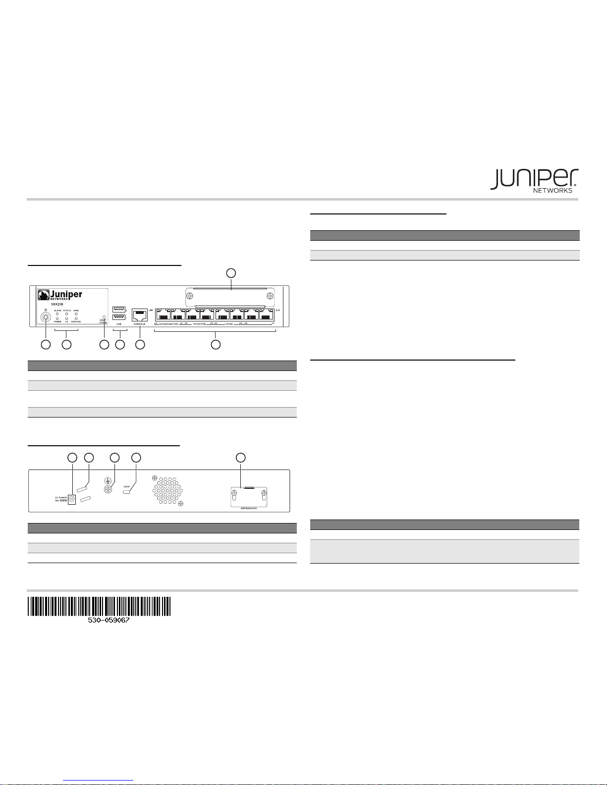
SRX210 Services Gateway Front Panel
SRX210 Services Gateway Back Panel
SRX210 Services Gateway Models
The following models of SRX210 Services Gateways are available:
On the SRX210HE2-POE model, Power over Ethernet (PoE) of 50 watts is supported
across four ports (0/0, 0/1, 0/2, and 0/3).
Note that you must use the following power supply adapters (supplied) for your services
gateway:
54V, 200 watts power supply adapters for the PoE model
12V, 60 watts power supply adapters for the non-PoE model
Connecting and Configuring the SRX Series Device
Use the instructions below to connect and set up the SRX210 Services Gateway to
protect your network. Refer to the LEDs on the front of the device to help you determine
the status of the device.
Overview
The SRX210 Services Gateway requires these basic configuration settings to function
properly:
Interfaces must be assigned IP addresses.
Interfaces must be bound to zones.
Policies must be configured between zones to permit or deny traffic.
Source NAT rules must be set.
The device has the following default configuration set when you power it on for the first
time. To use the device, you do not need to perform any initial configuration.
Factory-Default Settings:
Callout Description Callout Description
1 Mini-PIM slot 5 USB ports
2 Power button 6 Console port
3 LEDs: ALARM, POWER, STATUS,
HA, mPIM, EXPCARD
7 Gigabit Ethernet (0/0 and 0/1) and Fast
Ethernet (0/2 to 0/7) ports
4 RESET CONFIG button
Callout Description Callout Description
1 Power supply input 4 Lock for security cable
2 Cable tie holder 5 ExpressCard slot
3 Grounding point
g031132
1
5 6 723 4
g031113
52341
Device DDR Memory NAND Flash Memory
SRX210HE2 2 GB 2 GB
SRX210HE2-POE 2 GB 2 GB
Port Label Interface Security Zone DHCP State IP Address
0/0 ge-0/0/0 untrust client unassigned
0/1 and 0/2
to 0/7
ge-0/0/1 and
fe-0/0/2 to
fe-0/0/7
trust server 192.168.1.1/24
Page 2
Page 2
Factory-Default Settings for Security Policies:
Factory-Default Settings for NAT Rules:
NOTE: Source NAT translates the source address for packets coming from any number
of hosts on a private network to one public IP address.
Task 1: Connect the Power Cable to the Device
Connect the power supply adapter to the power supply point on the device and to a
power source. We recommend using a surge protector. Secure the connector to the
power supply point by wrapping a cable tie around the cable boot and the adjacent cable
tie holder. Note the following indications:
POWER LED (green): The device is receiving power.
STATUS LED (green): The device is operating normally.
ALARM LED (amber): The device is operating normally, but the LED might glow
amber if a rescue configuration has not been set. This is not a panic condition.
mPIM LED (off): The Mini-Physical Interface Module (Mini-PIM) is not present or is
not detected by the device. If this LED is solid green, it indicates that the Mini-PIM is
functioning normally.
NOTE:
After a rescue configuration has been set, an amber ALARM LED indicates a minor
alarm, and a solid red ALARM LED indicates a major problem on the services gateway.
You must allow the device between five and seven minutes to boot after you power it
on. Wait until the STATUS LED is solid green before proceeding to the next task.
Task 2: Connect the Management Device
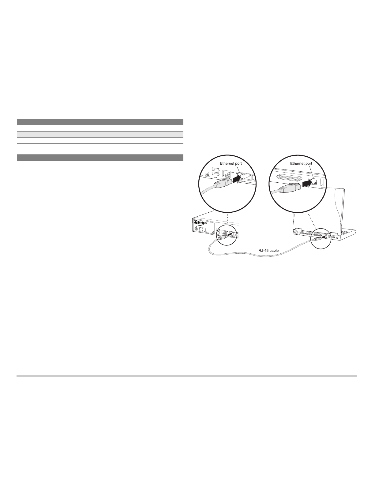
Connect the management device to the services gateway, using either of the following
methods:
Connect an RJ-45 cable (Ethernet cable) from one of the following ports on the front
panel to the Ethernet port on the management device (workstation or laptop):
0/1 (interface ge-0/0/1)
0/2 through 0/7 (interfaces fe-0/0/2 through fe-0/0/7)
We recommend this connection method. If you are using this method to connect,
proceed to Task 3.
Connect an RJ-45 cable (Ethernet cable) from the port labeled CONSOLE to the
supplied DB-9 adapter, which then connects to the serial port on the management
device (serial port settings: 9600 8-N-1).
If you are using this method to connect, proceed with the CLI configuration
instructions in the Getting Started Guide for the Branch SRX Series at
http://www.juniper.net/techpubs/en_US/release-independent/junos/
information-products/pathway-pages/srx-series/product/index.html.
See the following illustration for details about connecting the management interface by
using the Ethernet ports.
Task 3: Ensure That the Management Device Acquires an IP Address
After you connect the management device to the services gateway, the DHCP server
process on the services gateway automatically assigns an IP address to the
management device. Ensure that the management device acquires an IP address on the
192.168.1.0/24 subnetwork (other than 192.168.1.1) from the services gateway.
NOTE:
The services gateway functions as a DHCP server and will assign an IP address to
the management device.
If an IP address is not assigned to the management device, manually configure an
IP address in the 192.168.1.0/24 subnetwork. Do not assign the 192.168.1.1 IP
address to the management device because this IP address is assigned to the
services gateway. By default, the DHCP server is enabled on the L3 VLAN interface,
(IRB) vlan.0 (ge-0/0/1 and fe-0/0/2 to fe-0/0/7), which is configured with an IP
address of 192.168.1.1/24.
When an SRX210 Services Gateway is powered on for the first time, it boots using
the factory-default configuration.
Source Zone Destination Zone Policy Action
trust untrust permit
trust trust permit
untrust trust deny
Source Zone Destination Zone Policy Action
trust untrust source NAT to untrust zone interface
g031118
Page 3
Page 3
Task 4: Access the J-Web Interface
1. Launch a Web browser from the management device.
NOTE: The wizard works best with Mozilla Firefox version 15.x or later.
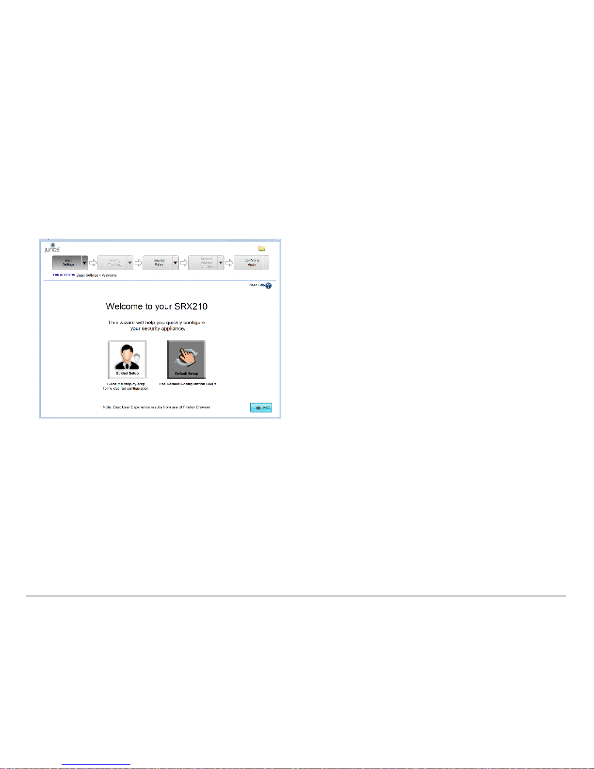
2. Type http://192.168.1.1 in the URL address field. The Welcome page appears.
Task 5: Select the Setup Mode
Use one of the following setup modes to configure the services gateway:
Guided Setup - Allows you to set up the services gateway in a custom security
configuration. In this mode, you can select either the Basic or the Expert option. If
you choose this mode, proceed to Task 7.
Default Setup - Allows you to quickly set up the services gateway in the default
configuration. In this mode, you can configure basic system settings, such as the
administrator password, and download purchased licenses. Any additional
configuration can be carried out after completing the wizard setup. If you choose this
mode, proceed to Task 6.
Task 6: Configure the Basic Settings in Default Setup Mode (Method 1)
Before you begin the configuration process, obtain a dynamic IP address. Use the port
labeled 0/0 (interface ge-0/0/0) to connect to your Internet service provider (ISP). Your
ISP will assign an IP address using the DHCP process.
NOTE: It is mandatory to configure only the device name and root password. You can
skip all the other steps by clicking Next to go directly to the Confirm & Apply page to
apply the configuration (Task 8).
1. From the Welcome page, click Default Setup. A warning message appears.
2. Click Yes to accept the default configuration mode.
3. From the Device Information page of the wizard, type the following information:
Device name of the services gateway; for example, SRX210.
Enter and confirm the root password.
NOTE: As you type in the password, the password evaluator indicates the
password strength. We recommend that you use a strong password, which
should contain 12 or more characters and include uppercase and lowercase
letters, numbers, and symbols.
To add users, click Add. Enter the username, password, and role. Click Done.
The username appears in the Administrative Accounts list box.
4. Click Next. The Device Time page appears.
5. Configure the system time by using one of the following options:
Time Server - Enter the NTP server name or IP address.
Manual - Enter the date and time.
6. Click Next. The Summary page appears.
7. Click Next. The Licenses page appears.
8. If you have purchased licenses, type your authorization code and click Download to
automatically retrieve the license. The Sign-in to License Management System page
appears.
9. If you have an existing support account, enter your e-mail address and password.
Click Next. The Licenses page appears. Select I Agree to accept the license and
click Done.
NOTE: If you do not have a support account, you can create a new account:
Enter your e-mail address and select Create New Account. Click Next.
From the Create Account page, enter your account information. Click Next. The
End User License page appears.
Select I AGREE to accept the license, and click Next.
Make a note of the new username and password. Click OK. You can change
the password by logging in to http://juniper.net/support.
After you submit an access authorization request, if your access is approved, you
will receive an e-mail in less than 24 hours. You can download the license only after
your access is approved.
Page 4

Page 4
10. Click Download Now to retrieve your licenses. A pop-up window appears displaying
the license information.
11. Review the downloaded licenses. Click OK and then Next.
12. Proceed to Task 8.
Task 7: Configure the Settings in Guided Setup Mode (Method 2)
Before you begin the configuration process, obtain a static IP address on your services
gateway. Use the port labeled 0/0 (interface ge-0/0/0) to connect to your ISP. Your ISP
will have provided a static IP address. You will not receive an IP address using the DHCP
process.
NOTE: It is mandatory to configure only the device name and root password. You can
skip all the other steps by clicking Next to go directly to the Confirm & Apply page to
apply the configuration (Task 8).
1. From the Welcome page, click Guided Setup and click Next. The Experience Level
page appears.
2. Select one of the following icons that best identifies your experience level, and click
Next:
Basic
Expert
The following table compares the Basic and Expert levels:
3. Configure the basic options:
a. Enter the device name and root password on the Device Information page.
NOTE: As you type in the password, the password evaluator indicates the
password strength. We recommend that you use a strong password, which
should contain 12 or more characters and include uppercase and lowercase
letters, numbers, and symbols.
b. To add users, click Add. Enter the username, password, and role. Click Done.
The username appears in the Administrative Accounts list box.
c. Click Next. The Device Time page appears.
d. Configure the system time by using one of the following options:
Time Server - Enter the NTP server name or IP address.
Manual - Enter the date and time.
e. Click Next. The Summary page appears displaying the basic device information
configured.
f. Click Next. The Security Topology Overview page appears.
4. Configure the security topology:
a. From the Security Topology Overview page, click Next. The Internet Zone
Setup Page appears.
b. Choose whether your internal network is connected to the Internet, and click
Next.
c. Select the device (SRX) to configure the Point-to-Point Protocol over Ethernet
(PPPoE) connection, and click Next. The Configuration page appears.
NOTE: If you select Not Applicable or DSL Modem, then a plain IP is
configured. Proceed to step e.
d. Type the username and password. Confirm the password, and click Next.
e. Configure the Internet zone. Select the Static option. Click Add IP to enter the
static IP address provided by your ISP, and click Done. Select the port to use,
and click Next. The DMZ Setup page appears.
f. If you are using the DMZ, click Ye s and configure the DMZ for your network by
following the onscreen instructions. Otherwise, click No and proceed to Step g.
g. From the Internal Zone Setup page, select the topology that best represents
your network, and click Next.
h. Configure the internal zones. Type the name for the zone, select the port to use
with this zone, and click Next.
i. Configure the DHCP server for the internal zone. Click Done. The Summary
page appears displaying the details for the security topology configuration.
j. Click Next. The Security Policy Overview page appears.
5. Configure the security policy:
The Security Policy section allows you to configure policies between the Internet,
the DMZ, and internal zones.
NOTE: The wizard recommends security policies based on the security topology
you have defined.
a. From the Security Policy Overview page, click Next. The Licenses page
appears.
b. Download the license. Refer to Step 8 through Step 11 of Task 6.
c. If you have configured the DMZ, configure the DMZ policy for the traffic
between the Internet zone and the DMZ. Click Next.
d. Configure the internal policy for the traffic between the Internet zone and the
internal zones. Click Next.
e. If you have configured the DMZ, configure the DMZ policy for the traffic
between the internal zone and the DMZ.
f. Configure the security policy for the Device Management interface by zone.
Basic Expert
Can configure only three internal zones Can configure more than three internal
zones
Can configure static and dynamic IP for the Internet
zone
Can configure static IP, static pool, and
dynamic IP for the Internet zone
Cannot configure internal zone service Can configure internal zone service
Cannot configure internal destination NAT Can configure internal destination NAT
Page 5
Page 5
g. Specify if you would like to provide remote access to your internal and DMZ
zones. If you select Yes, configure the settings for remote access. Enter the
remote client IP pool range and remote user accounts.
h. Click Next on the Summary page. The Network Address Translation Overview
page appears.
6. Configure NAT:
The Network Address Translation section allows you to enable source NAT and
destination NAT.
NOTE: The wizard recommends destination NAT rules based on the enabled zone
services in the DMZ or internal topology.
a. From the Network Address Translation Overview page, click Next. The Internal
Source NAT page appears.
b. Select the internal zones for which the source NAT must be added. Click Next.
c. Add the internal destination NAT and click Next.
NOTE: The internal destination NAT configuration option is available only for
the Expert level.
d. Add the destination NAT for the DMZ and click Next. The Summary page
appears.
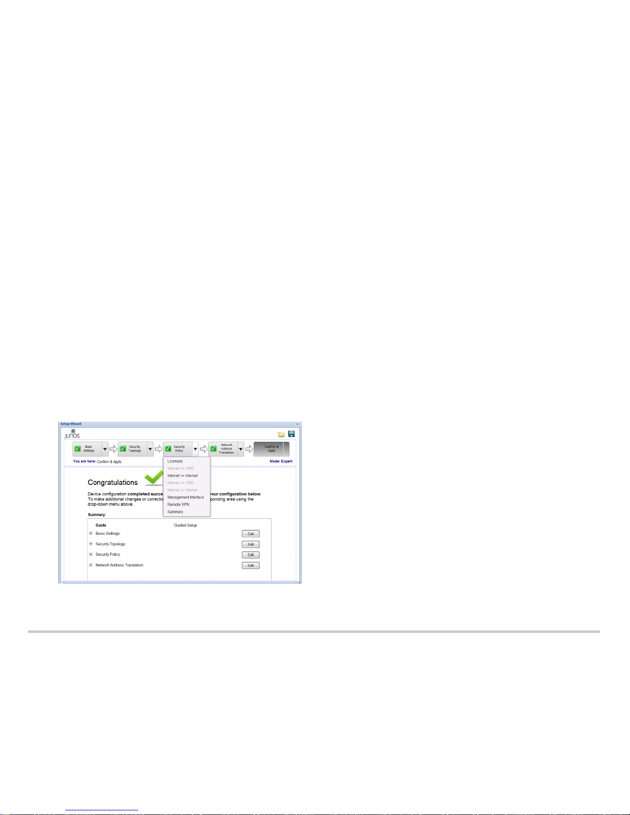
NOTE: To make any changes, click the Edit button or navigate to the
corresponding section from the drop-down menu at the top of the page.
e. Click Next. The Confirm & Apply page appears.
Task 8: Apply the Basic Configuration
To apply the configuration settings for the services gateway:
1. Review and ensure that the configuration settings are correct, and click Next. The
Commit Configuration page appears.
2. Click Apply Settings to apply the configuration changes to the services gateway.
NOTE: Check the connectivity to the services gateway, because you might lose
connectivity if you have changed the management zone IP. Click the URL for
reconnection instructions for information on how to reconnect to the device.
3. Click Done to complete the setup.
After successful completion of the setup, you are redirected to the J-Web interface.
IMPORTANT: After you complete the initial setup configuration, you can relaunch the
J-Web Setup wizard by clicking Tasks > Run Setup Wizard. You can either edit an
existing configuration or create a new configuration. Note that If you elect to create a new
configuration, then all the current configuration in the services gateway will be deleted.
NOTE: To make any changes to the interface configuration, see the Getting Started
Guide for the Branch SRX Series at
http://www.juniper.net/techpubs/en_US/release-independent/junos/information-products/
pathway-pages/srx-series/product/index.html.
Task 9: Verify the Configuration
Access http://www.juniper.net to ensure that you are connected to the Internet. This
connectivity ensures that you can pass traffic through the services gateway.
NOTE: If the http://www.juniper.net page does not load, verify your configuration settings,
and ensure that you have applied the configuration.
After you complete these steps, you can pass traffic from any trust port to the untrust
port.
Page 6

Juniper Networks, Junos, Steel-Belted Radius, NetScreen, and ScreenOS are registered trademarks of Juniper Networks, Inc. in the United States and other countries. The Juniper Networks Logo, the Junos logo, and JunosE are
trademarks of Juniper Networks, Inc. All other trademarks, service marks, registered trademarks, or registered service marks are the property of their respective owners. Juniper Networks assumes no responsibility for any inaccuracies
in this document. Juniper Networks reserves the right to change, modify, transfer, or otherwise revise this publication without notice. Products made or sold by Juniper Networks or components thereof might be covered by one or more
of the following patents that are owned by or licensed to Juniper Networks: U.S. Patent Nos. 5,473,599, 5,905,725, 5,909,440, 6,192,051, 6,333,650, 6,359,479, 6,406,312, 6,429,706, 6,459,579, 6,493,347, 6,538,518, 6,538,899,
6,552,918, 6,567,902, 6,578,186, and 6,590,785. Copyright © 2015, Juniper Networks, Inc. All rights reserved. Par
t Number: 530-059067 Rev. 01, March 2015.
Powering Off the Device
You can power off the device in one of the following ways:
Graceful shutdown—Press and immediately release the Power button. The device
begins gracefully shutting down the operating system.
Forced shutdown—Press the Power button, and hold it for 10 seconds. The device
immediately shuts down. Press the Power button again to power on the device.
You can reboot or halt the system in the J-Web interface by selecting Maintain >
Reboot.
NOTE: Use the graceful shutdown method to halt, power off, or reboot the services
gateway. Use the forced shutdown method as a last resort to recover the services
gateway if the services gateway operating system is not responding to the graceful
shutdown method.
For additional configuration information, see the Getting Started Guide for the Branch
SRX Series at
http://www.juniper.net/techpubs/en_US/release-independent/junos/information-products/
pathway-pages/srx-series/product/index.html.
For detailed software configuration information, see the software documentation
available at
http://www.juniper.net/techpubs/en_US/release-independent/junos/information-products/
pathway-pages/srx-series/product/index.html.
Using the Reset Config Button
If a configuration fails or denies management access to the services gateway, you can
use the Reset Config button to restore the device to the factory-default configuration or to
a rescue configuration. For example, if someone inadvertently commits a configuration
that denies management access to the services gateway, you can delete the invalid
configuration and replace it with a rescue configuration by pressing the Reset Config
button.
NOTE: The Reset Config button is recessed to prevent it from being pressed
accidentally.
The rescue configuration is a previously committed, valid configuration. You must have
previously set the rescue configuration through the J-Web interface or the CLI.
To press the Reset Config button, insert a small probe (such as a straightened paper clip)
into the pinhole on the front panel:
By default, pressing and quickly releasing the Reset Config button loads and
commits the rescue configuration through the J-Web interface or the CLI. The Status
LED is solid amber during this time.
By default, pressing and holding the Reset Config button for 15 seconds or
more—until the STATUS LED is solid amber—deletes all configurations on the
device, including the backup configurations and rescue configuration, and loads and
commits the factory configuration.
For details about managing and monitoring your device, see the Junos OS
Administration Guide and the Junos OS CLI Reference Guide.
Contacting Juniper Networks
For technical support, see http://www.juniper.net/support/requesting-support.html.
 Loading...