


SRX1500 Services Gateway Hardware
Published
2020-11-10
Guide

Juniper Networks, Inc.
1133 Innovation Way
Sunnyvale, California 94089
USA
408-745-2000
www.juniper.net
Juniper Networks, the Juniper Networks logo, Juniper, and Junos are registered trademarks of Juniper Networks, Inc. in
the United States and other countries. All other trademarks, service marks, registered marks, or registered service marks
are the property of their respective owners.
Juniper Networks assumes no responsibility for any inaccuracies in this document. Juniper Networks reserves the right
to change, modify, transfer, or otherwise revise this publication without notice.
SRX1500 Services Gateway Hardware Guide
Copyright © 2020 Juniper Networks, Inc. All rights reserved.
The information in this document is current as of the date on the title page.
ii
YEAR 2000 NOTICE
Juniper Networks hardware and software products are Year 2000 compliant. Junos OS has no known time-related
limitations through the year 2038. However, the NTP application is known to have some difficulty in the year 2036.
END USER LICENSE AGREEMENT
The Juniper Networks product that is the subject of this technical documentation consists of (or is intended for use with)
Juniper Networks software. Use of such software is subject to the terms and conditions of the End User License Agreement
(“EULA”) posted at https://support.juniper.net/support/eula/. By downloading, installing or using such software, you
agree to the terms and conditions of that EULA.

Table of Contents
1
About the Documentation | viii
Documentation and Release Notes | viii
Using the Examples in This Manual | viii
Merging a Full Example | ix
Merging a Snippet | x
Documentation Conventions | x
Documentation Feedback | xiii
Requesting Technical Support | xiii
Self-Help Online Tools and Resources | xiv
Creating a Service Request with JTAC | xiv
iii
Overview
SRX1500 Services Gateway Overview | 16
SRX1500 Services Gateway Overview | 16
SRX1500 Services Gateway Field Replaceable Units Overview | 17
Benefits of the SRX1500 Services Gateway | 17
SRX1500 Chassis | 18
SRX1500 Services Gateway Chassis Overview | 18
SRX1500 Services Gateway Front Panel | 18
Management Port LEDs | 22
Network Port LEDs | 22
HA Port LEDs | 23
SRX1500 Services Gateway Back Panel | 23
SRX1500 Cooling System | 24
SRX1500 Power System | 25
SRX1500 Services Gateway Power Supply | 25
SRX1500 Services Gateway Supported AC Power Cords | 27
SRX1500 Services Gateway AC Power Supply Electrical Specifications | 28
SRX1500 Services Gateway DC Power Supply Electrical Specifications | 28
SRX1500 Services Gateway DC Power Cable Specifications | 29

Site Planning, Preparation, and Specifications
2
3
Site Preparation Checklist for the SRX1500 Services Gateway | 31
SRX1500 Site Guidelines and Requirements | 33
SRX1500 Services Gateway General Site Installation Guidelines | 33
SRX1500 Services Gateway Environmental Specifications | 34
SRX1500 Services Gateway Electrical Wiring Guidelines | 34
SRX1500 Services Gateway Grounding Specifications | 36
SRX1500 Services Gateway Physical Specifications | 36
SRX1500 Services Gateway Clearance Requirements for Airflow and Hardware
Maintenance | 37
Rack Requirements | 39
Cabinet Requirements | 39
SRX1500 Transceiver Specifications and Pinouts | 40
iv
SRX1500 Transceiver Support | 40
RJ-45 Connector Pinouts for the SRX1500 Services Gateway Ethernet Port | 41
RJ-45 Connector Pinouts for the SRX1500 Services Gateway Console Port | 41
Mini-USB Connector Pinouts for the SRX1500 Services Gateway Console Port | 42
Initial Installation and Configuration
SRX1500 Services Gateway Installation Overview | 45
Unpacking and Mounting the SRX1500 | 45
Unpacking the SRX1500 Services Gateway | 46
Verifying Parts Received with the SRX1500 Services Gateway | 46
Preparing the SRX1500 Services Gateway for Rack-Mount Installation | 48
Installing the SRX1500 Services Gateway in a Rack | 48
Connecting the SRX1500 to Power | 50
Required Tools and Parts for Grounding the SRX1500 Services Gateway | 50
Connecting the SRX1500 Services Gateway Grounding Cable | 50
Installing an AC Power Supply on the SRX1500 Services Gateway | 52
Connecting the SRX1500 Services Gateway to an AC Power Supply | 53
Installing a DC Power Supply on the SRX1500 Services Gateway | 54
Connecting the SRX1500 Services Gateway to a DC Power Supply | 57

Powering On the SRX1500 Services Gateway | 58
4
Powering Off the SRX1500 Services Gateway | 59
Connecting the SRX1500 to External Devices | 60
Required Tools and Parts for Connecting the SRX1500 Services Gateway | 60
Connecting the SRX1500 Services Gateway to a Network for Out-of-Band Management | 60
Connecting the SRX1500 Services Gateway to a Management Console | 61
Configuring Junos OS on the SRX1500 | 62
SRX1500 Services Gateway Software Configuration Overview | 63
Understanding SRX1500 Services Gateway Factory-Default Settings | 63
Viewing SRX1500 Services Gateway Factory-Default Settings | 63
Accessing J-Web on the SRX1500 Services Gateway | 64
Configuring the SRX1500 Services Gateway Using J-Web | 64
Configuring Root Authentication and the Management Interface from the CLI | 65
v
Configuring Interfaces, Zones, and Policies with J-Web | 66
Accessing the CLI on the SRX1500 Services Gateway | 69
Connecting to the SRX1500 Services Gateway from the CLI Remotely | 70
Configuring the SRX1500 Services Gateway Using the CLI | 70
Maintaining Components
Maintaining the SRX1500 Components | 78
Required Tools and Parts for Maintaining the SRX1500 Services Gateway | 78
Routine Maintenance Procedures for the SRX1500 Services Gateway | 78
Maintaining the SRX1500 Power System | 79
Maintaining the SRX1500 Services Gateway Power Supply | 79
Required Tools and Parts for Replacing the SRX1500 Services Gateway Components | 79
Replacing an AC Power Supply on the SRX1500 Services Gateway | 80
Disconnecting an AC Power Cord from the SRX1500 Services Gateway | 80
Removing an AC Power Supply from the SRX1500 Services Gateway | 80
Replacing a DC Power Supply on the SRX1500 Services Gateway | 82
Removing a DC Power Supply Cable from the SRX1500 Services Gateway | 82
Removing a DC Power Supply on the SRX1500 Services Gateway | 83

Troubleshooting Hardware
5
6
7
Troubleshooting the SRX1500 | 86
Troubleshooting Resources for the SRX1500 Services Gateway Overview | 86
Troubleshooting Chassis and Interface Alarm Messages on the SRX1500 Services Gateway | 86
Troubleshooting the Power System on the SRX1500 Services Gateway | 88
Using the RESET CONFIG Button on the SRX1500 Services Gateway | 90
Contacting Customer Support and Returning the Chassis or Components
Returning the SRX1500 Chassis or Components | 92
Contacting Customer Support | 92
Returning a SRX1500 Services Gateway Component to Juniper Networks | 93
Locating the SRX1500 Services Gateway Chassis Serial Number and Agency Labels | 93
Listing the SRX1500 Services Gateway Component Details with the CLI | 94
vi
Required Tools and Parts for Packing the SRX1500 Services Gateway | 95
Packing the SRX1500 Services Gateway for Shipment | 95
Packing SRX1500 Services Gateway Components for Shipment | 96
Safety and Compliance Information
Definitions of Safety Warning Levels | 99
General Safety Guidelines and Warnings | 102
Restricted Access Warning | 104
Qualified Personnel Warning | 107
Prevention of Electrostatic Discharge Damage | 107
Fire Safety Requirements | 109
Fire Suppression | 109
Fire Suppression Equipment | 109
Laser and LED Safety Guidelines and Warnings | 110
General Laser Safety Guidelines | 110
Class 1 Laser Product Warning | 111
Class 1 LED Product Warning | 112
Laser Beam Warning | 113

Radiation from Open Port Apertures Warning | 114
Maintenance and Operational Safety Guidelines and Warnings | 115
Battery Handling Warning | 116
Jewelry Removal Warning | 117
Lightning Activity Warning | 119
Operating Temperature Warning | 120
Product Disposal Warning | 122
Action to Take After an Electrical Accident | 123
General Electrical Safety Guidelines and Warnings | 123
Safety Guidelines and Warnings | 123
Grounded Equipment Warning | 124
Backplane Energy Hazard Warning | 124
vii
Multiple Power Supplies Disconnection Warning | 125
Power Disconnection Warning | 126
TN Power Warning | 127
Copper Conductors Warning | 128
AC Power Electrical Safety Guidelines | 129
DC Power Electrical Safety Guidelines | 130
DC Power Electrical Safety Guidelines | 130
DC Power Disconnection Warning | 132
DC Power Grounding Requirements and Warning | 134
DC Power Wiring Sequence Warning | 136
DC Power Wiring Terminations Warning | 139
SRX1500 Services Gateway Agency Approvals | 141
SRX1500 Services Gateway Acoustic Noise Compliance Statements | 142
SRX1500 Services Gateway EMC Requirements | 143
Canada | 143
European Community | 143
Israel | 143
Japan | 144
United States | 144
About the Documentation
IN THIS SECTION
Documentation and Release Notes | viii
Using the Examples in This Manual | viii
Documentation Conventions | x
Documentation Feedback | xiii
Requesting Technical Support | xiii
Use this guide to install hardware and perform initial software configuration, routine maintenance, and
troubleshooting for the SRX1500 Services Gateway. After completing the installation and basic configuration
procedures covered in this guide, refer to the Junos OS documentation for information about further
software configuration.
viii
Documentation and Release Notes
To obtain the most current version of all Juniper Networks®technical documentation, see the product
documentation page on the Juniper Networks website at https://www.juniper.net/documentation/.
If the information in the latest release notes differs from the information in the documentation, follow the
product Release Notes.
Juniper Networks Books publishes books by Juniper Networks engineers and subject matter experts.
These books go beyond the technical documentation to explore the nuances of network architecture,
deployment, and administration. The current list can be viewed at https://www.juniper.net/books.
Using the Examples in This Manual
If you want to use the examples in this manual, you can use the load merge or the load merge relative
command. These commands cause the software to merge the incoming configuration into the current
candidate configuration. The example does not become active until you commit the candidate configuration.

If the example configuration contains the top level of the hierarchy (or multiple hierarchies), the example
is a full example. In this case, use the load merge command.
If the example configuration does not start at the top level of the hierarchy, the example is a snippet. In
this case, use the load merge relative command. These procedures are described in the following sections.
Merging a Full Example
To merge a full example, follow these steps:
1. From the HTML or PDF version of the manual, copy a configuration example into a text file, save the
file with a name, and copy the file to a directory on your routing platform.
For example, copy the following configuration to a file and name the file ex-script.conf. Copy the
ex-script.conf file to the /var/tmp directory on your routing platform.
system {
scripts {
commit {
file ex-script.xsl;
}
}
}
interfaces {
fxp0 {
disable;
unit 0 {
family inet {
address 10.0.0.1/24;
}
}
}
}
ix
2. Merge the contents of the file into your routing platform configuration by issuing the load merge
configuration mode command:
[edit]
user@host# load merge /var/tmp/ex-script.conf
load complete

Merging a Snippet
To merge a snippet, follow these steps:
1. From the HTML or PDF version of the manual, copy a configuration snippet into a text file, save the
file with a name, and copy the file to a directory on your routing platform.
For example, copy the following snippet to a file and name the file ex-script-snippet.conf. Copy the
ex-script-snippet.conf file to the /var/tmp directory on your routing platform.
commit {
file ex-script-snippet.xsl; }
2. Move to the hierarchy level that is relevant for this snippet by issuing the following configuration mode
command:
[edit]
user@host# edit system scripts
[edit system scripts]
x
3. Merge the contents of the file into your routing platform configuration by issuing the load merge
relative configuration mode command:
[edit system scripts]
user@host# load merge relative /var/tmp/ex-script-snippet.conf
load complete
For more information about the load command, see CLI Explorer.
Documentation Conventions
Table 1 on page xi defines notice icons used in this guide.
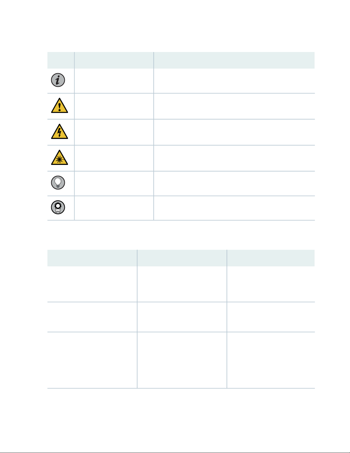
Table 1: Notice Icons
xi
DescriptionMeaningIcon
Indicates important features or instructions.Informational note
Caution
Indicates a situation that might result in loss of data or hardware
damage.
Alerts you to the risk of personal injury or death.Warning
Alerts you to the risk of personal injury from a laser.Laser warning
Indicates helpful information.Tip
Alerts you to a recommended use or implementation.Best practice
Table 2 on page xi defines the text and syntax conventions used in this guide.
Table 2: Text and Syntax Conventions
ExamplesDescriptionConvention
Fixed-width text like this
Italic text like this
Represents text that you type.Bold text like this
Represents output that appears on
the terminal screen.
Introduces or emphasizes important
•
new terms.
Identifies guide names.
•
Identifies RFC and Internet draft
•
titles.
To enter configuration mode, type
the configure command:
user@host> configure
user@host> show chassis alarms
No alarms currently active
A policy term is a named structure
•
that defines match conditions and
actions.
Junos OS CLI User Guide
•
RFC 1997, BGP Communities
•
Attribute

Table 2: Text and Syntax Conventions (continued)
xii
ExamplesDescriptionConvention
Italic text like this
Text like this
< > (angle brackets)
| (pipe symbol)
Represents variables (options for
which you substitute a value) in
commands or configuration
statements.
Represents names of configuration
statements, commands, files, and
directories; configuration hierarchy
levels; or labels on routing platform
components.
variables.
Indicates a choice between the
mutually exclusive keywords or
variables on either side of the symbol.
The set of choices is often enclosed
in parentheses for clarity.
Configure the machine’s domain
name:
[edit]
root@# set system domain-name
domain-name
To configure a stub area, include
•
the stub statement at the [edit
protocols ospf area area-id]
hierarchy level.
The console port is labeled
•
CONSOLE.
stub <default-metric metric>;Encloses optional keywords or
broadcast | multicast
(string1 | string2 | string3)
# (pound sign)
[ ] (square brackets)
Indention and braces ( { } )
; (semicolon)
GUI Conventions
Indicates a comment specified on the
same line as the configuration
statement to which it applies.
Encloses a variable for which you can
substitute one or more values.
Identifies a level in the configuration
hierarchy.
Identifies a leaf statement at a
configuration hierarchy level.
rsvp { # Required for dynamic MPLS
only
community name members [
community-ids ]
[edit]
routing-options {
static {
route default {
nexthop address;
retain;
}
}
}
Table 2: Text and Syntax Conventions (continued)
xiii
ExamplesDescriptionConvention
Bold text like this
> (bold right angle bracket)
Represents graphical user interface
(GUI) items you click or select.
Separates levels in a hierarchy of
menu selections.
In the Logical Interfaces box, select
•
All Interfaces.
To cancel the configuration, click
•
Cancel.
In the configuration editor hierarchy,
select Protocols>Ospf.
Documentation Feedback
We encourage you to provide feedback so that we can improve our documentation. You can use either
of the following methods:
Online feedback system—Click TechLibrary Feedback, on the lower right of any page on the Juniper
•
Networks TechLibrary site, and do one of the following:
Click the thumbs-up icon if the information on the page was helpful to you.
•
Click the thumbs-down icon if the information on the page was not helpful to you or if you have
•
suggestions for improvement, and use the pop-up form to provide feedback.
E-mail—Send your comments to techpubs-comments@juniper.net. Include the document or topic name,
•
URL or page number, and software version (if applicable).
Requesting Technical Support
Technical product support is available through the Juniper Networks Technical Assistance Center (JTAC).
If you are a customer with an active Juniper Care or Partner Support Services support contract, or are

covered under warranty, and need post-sales technical support, you can access our tools and resources
online or open a case with JTAC.
JTAC policies—For a complete understanding of our JTAC procedures and policies, review the JTAC User
•
Guide located at https://www.juniper.net/us/en/local/pdf/resource-guides/7100059-en.pdf.
Product warranties—For product warranty information, visit https://www.juniper.net/support/warranty/.
•
JTAC hours of operation—The JTAC centers have resources available 24 hours a day, 7 days a week,
•
365 days a year.
Self-Help Online Tools and Resources
For quick and easy problem resolution, Juniper Networks has designed an online self-service portal called
the Customer Support Center (CSC) that provides you with the following features:
Find CSC offerings: https://www.juniper.net/customers/support/
•
Search for known bugs: https://prsearch.juniper.net/
•
xiv
Find product documentation: https://www.juniper.net/documentation/
•
Find solutions and answer questions using our Knowledge Base: https://kb.juniper.net/
•
Download the latest versions of software and review release notes:
•
https://www.juniper.net/customers/csc/software/
Search technical bulletins for relevant hardware and software notifications:
•
https://kb.juniper.net/InfoCenter/
Join and participate in the Juniper Networks Community Forum:
•
https://www.juniper.net/company/communities/
Create a service request online: https://myjuniper.juniper.net
•
To verify service entitlement by product serial number, use our Serial Number Entitlement (SNE) Tool:
https://entitlementsearch.juniper.net/entitlementsearch/
Creating a Service Request with JTAC
You can create a service request with JTAC on the Web or by telephone.
Visit https://myjuniper.juniper.net.
•
Call 1-888-314-JTAC (1-888-314-5822 toll-free in the USA, Canada, and Mexico).
•
For international or direct-dial options in countries without toll-free numbers, see
https://support.juniper.net/support/requesting-support/.

1
CHAPTER
Overview
SRX1500 Services Gateway Overview | 16
SRX1500 Chassis | 18
SRX1500 Cooling System | 24
SRX1500 Power System | 25
SRX1500 Services Gateway Overview
IN THIS SECTION
SRX1500 Services Gateway Overview | 16
SRX1500 Services Gateway Field Replaceable Units Overview | 17
Benefits of the SRX1500 Services Gateway | 17
SRX1500 Services Gateway Overview
Juniper Networks SRX1500 Services Gateway expands the SRX Series family of security platforms. The
SRX1500 Services Gateway is a mid-range dynamic services gateway that consolidates security functionality
and uncompromised performance for small to medium enterprises. With advanced security and threat
mitigation capabilities, the SRX1500 Services Gateway provides campus edge Integrated Security Appliance
(ISA) support.
16
The SRX1500 Services Gateway has a modular 1U chassis with twelve 1G Ethernet ports, four 1G SFP
ports, and four 10G SFP+ ports. It contains two slots for WAN Physical Interface Modules (PIMs), one slot
for an SSD device, and two slots for power supplies.
The SRX1500 Services Gateway is available in two models:
SRX1500 (AC)–SRX1500 Services Gateway with a 120 GB SSD (with 100 GB usable space) and AC
•
power supply
SRX1500 (DC)–SRX1500 Services Gateway with a 120 GB SSD (with 100 GB usable space) and DC
•
power supply
The SRX1500 Services Gateway runs the Junos operating system (Junos OS) and supports the following
features:
Firewall support with key features such as IPsec and VPN
•
Advanced security services (IPS, AppID, UTM) and threat mitigation capabilities
•
High availability
•
QoS
•
Secure boot
•
Juniper Sky Advanced Threat Prevention (Juniper SkyATP)
•

The services gateway runs the Junos OS and can be managed using the CLI, Junos Space, and J-Web.
SRX1500 Services Gateway Field Replaceable Units Overview
Field-replaceable units (FRUs) are components that you can replace at your site. The power supplies are
the only FRUs on the SRX1500 Services Gateway. The power supplies (if redundant) are hot-swappable.
You can remove and replace the power supply without powering off the services gateway or disrupting
the services gateway functions.
SEE ALSO
Required Tools and Parts for Replacing the SRX1500 Services Gateway Components | 79
Replacing an AC Power Supply on the SRX1500 Services Gateway | 80
Replacing a DC Power Supply on the SRX1500 Services Gateway | 82
17
Benefits of the SRX1500 Services Gateway
High performance—The SRX1500 supports up to 9-Gbps of firewall throughput and is suited for enterprise
•
campus and data center edge deployments.
Simplified deployment with minimal manual intervention—The Zero Touch Provisioning (ZTP) feature
•
enables you to provision and configure the SRX1500 automatically, thereby reducing operational
complexity and simplifying the provisioning of new sites.
Advanced threat protection—The SRX1500 supports the intrusion prevention system (IPS), Juniper Sky
•
Advanced Threat Prevention (Juniper Sky ATP), antivirus, and antispam features, which protect against
potential vulnerabilities. Juniper Sky ATP protects against zero-day attacks and other unknown threats.
RELATED DOCUMENTATION
SRX1500 Services Gateway Installation Overview | 45
SRX1500 Chassis
IN THIS SECTION
SRX1500 Services Gateway Chassis Overview | 18
SRX1500 Services Gateway Front Panel | 18
SRX1500 Services Gateway Back Panel | 23
SRX1500 Services Gateway Chassis Overview
The SRX1500 Services Gateway chassis is a rigid sheet metal structure that houses all the other hardware
components. The chassis weighs 15 lb. and measures 1.75 in. high, 17.5 in. wide, and 18.2 in. deep. The
chassis installs in standard 600-mm deep (or larger) enclosed cabinets or 19-in. equipment racks.
18
CAUTION: Before removing or installing components of a functioning services
gateway, attach an electrostatic discharge (ESD) strap to an ESD point and place the
other end of the strap around your bare wrist. Failure to use an ESD strap could result
in damage to the device.
The services gateway must be connected to earth ground during normal operation. The protective earthing
terminal on the rear of the chassis is provided to connect the services gateway to ground. Additional
grounding is provided to an AC-powered services gateway when you plug its power supply into a grounded
AC power receptacle.
SRX1500 Services Gateway Front Panel
Figure 1 on page 19 shows the front panel of the SRX1500 Services Gateway. The front panel contains
LEDs, Power and Reset Config buttons, and various ports.
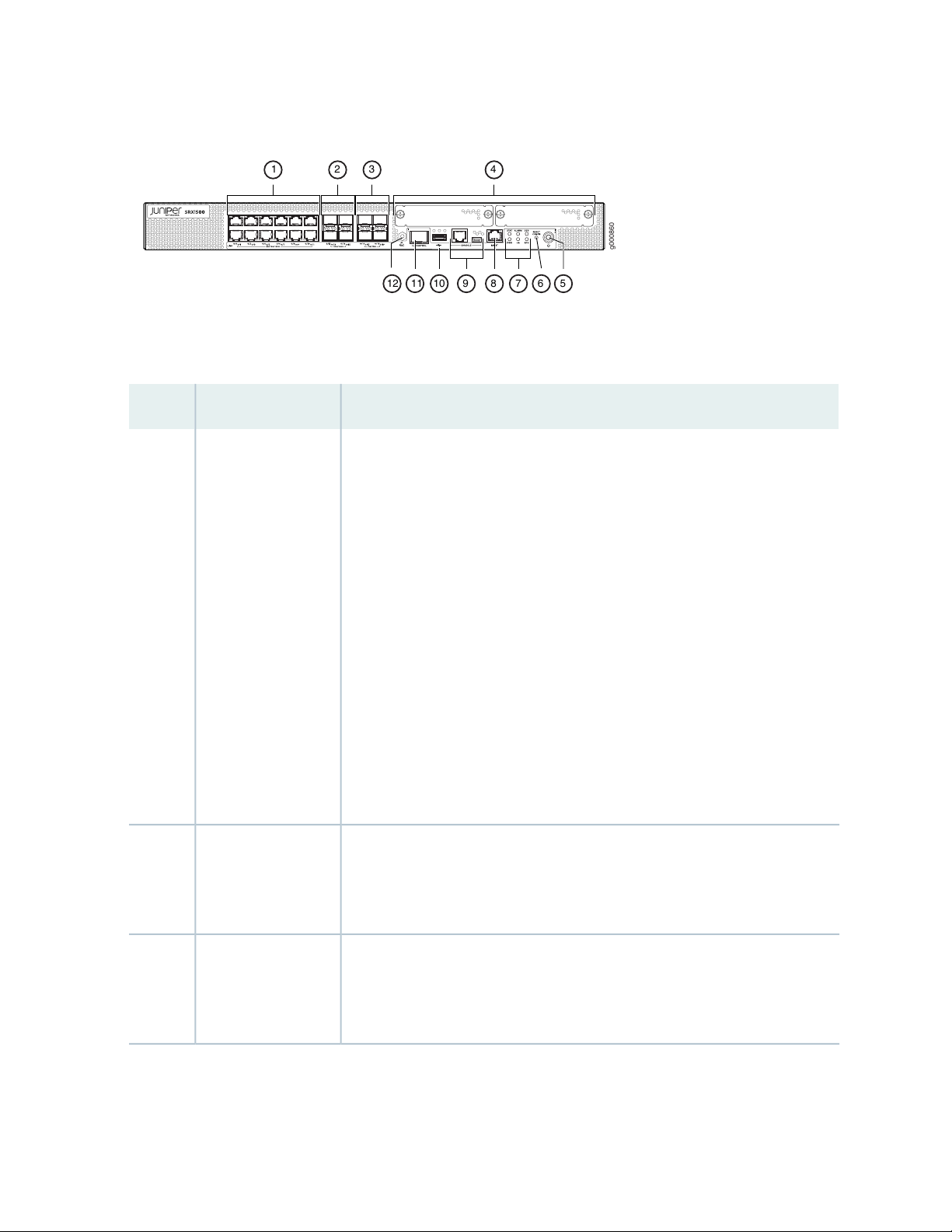
Figure 1: SRX1500 Services Gateway Front Panel
g000860
1 2 3 4
56789101112
Table 3 on page 19 provides information about the front panel components of the services gateway.
Table 3: SRX1500 Services Gateway Front Panel Components
DescriptionComponentCallout
19
1
10/100/1000 Base-T
ports
100/1000 SFP ports2
Twelve 10/100/1000 Base-T ports.
Top: 0/0, 0/2, 0/4, 0/6, 0/8, and 0/10
Bottom: 0/1, 0/3, 0/5, 0/7, 0/9, and 0/11
The ports have the following characteristics:
Use an RJ-45 connector.
•
Operate in full-duplex and half-duplex modes.
•
Support flow control.
•
Support autonegotiation.
•
The ports can be used to:
Function as front-end network ports.
•
Provide LAN and WAN connectivity to hubs, switches, local servers, and
•
workstations.
Forward incoming data packets to the services gateway.
•
Receive outgoing data packets from the services gateway
•
Four 1-Gigabit Ethernet small form-factor pluggable (SFP) ports for network
traffic
Top: 0/12 and 0/14
Bottom: 0/13 and 0/15
1G/10G SFP+ ports3
Four 1-Gigabit Ethernet/10-Gigabit Ethernet enhanced small form-factor
pluggable (SFP+) ports for network traffic
Top: 0/16 and 0/18
Bottom: 0/17 and 0/19

Table 3: SRX1500 Services Gateway Front Panel Components (continued)
DescriptionComponentCallout
20
WAN PIM slots4
Power button5
LEDs7
Console port9
Two WAN PIM slots.
WAN PIMs are used to add WAN interfaces to the services gateway.
NOTE: The WAN PIMs are currently not available for ordering.
Use the Power button to shut down the services gateway. On a services gateway
that has been previously shut down using the Power button, when the power
button is pressed again the services gateway starts up.
Returns the services gateway to the factory-default configuration.Reset config button6
Indicate component and system status and troubleshooting information at a
glance. See Table 4 on page 21.
Use the management (MGMT) port to connect to the device over the network.Management port8
Serial—Connects a laptop to the services gateway for CLI management. The
•
port uses an RJ-45 serial connection, is configured as DTE, and supports the
RS-232 (EIA-232) standard.
USB—Connects a laptop to the services gateway for CLI management through
•
a USB interface. The port accepts a Mini-B type USB cable plug. A USB cable
with Mini-B and Type A USB plugs is supplied with the services gateway. To
use the mini-USB console port, you must download a USB driver to the
management device from the Silicon Labs page.
The services gateway has one USB port that accepts a USB storage device.USB port10
HA control port11
ESD point12
Dedicated Gigabit Ethernet SFP port to synchronize data and maintain state
information in a chassis cluster setup.
For personal safety, while working on the services gateway, use the ESD outlet
to plug in an ESD grounding strap to prevent your body from sending static
charges to the services gateway.
NOTE: For information on supported transceivers, see the Hardware Compatibility Tool. Note
that the HA control port supports only the following transceivers:
EX-SFP-1GE-LH
•
EX-SFP-1GE-LX
•
EX-SFP-1GE-SX
•
EX-SFP-1GE-SX-ET
•
QFX-SFP-1GE-LX
•
QFX-SFP-1GE-SX
•
SRX-SFP-1GE-LH
•
SRX-SFP-1GE-LX
•
SRX-SFP-1GE-LX-ET
•
SRX-SFP-1GE-SX
•
21
SRX-SFP-1GE-SX-ET
•
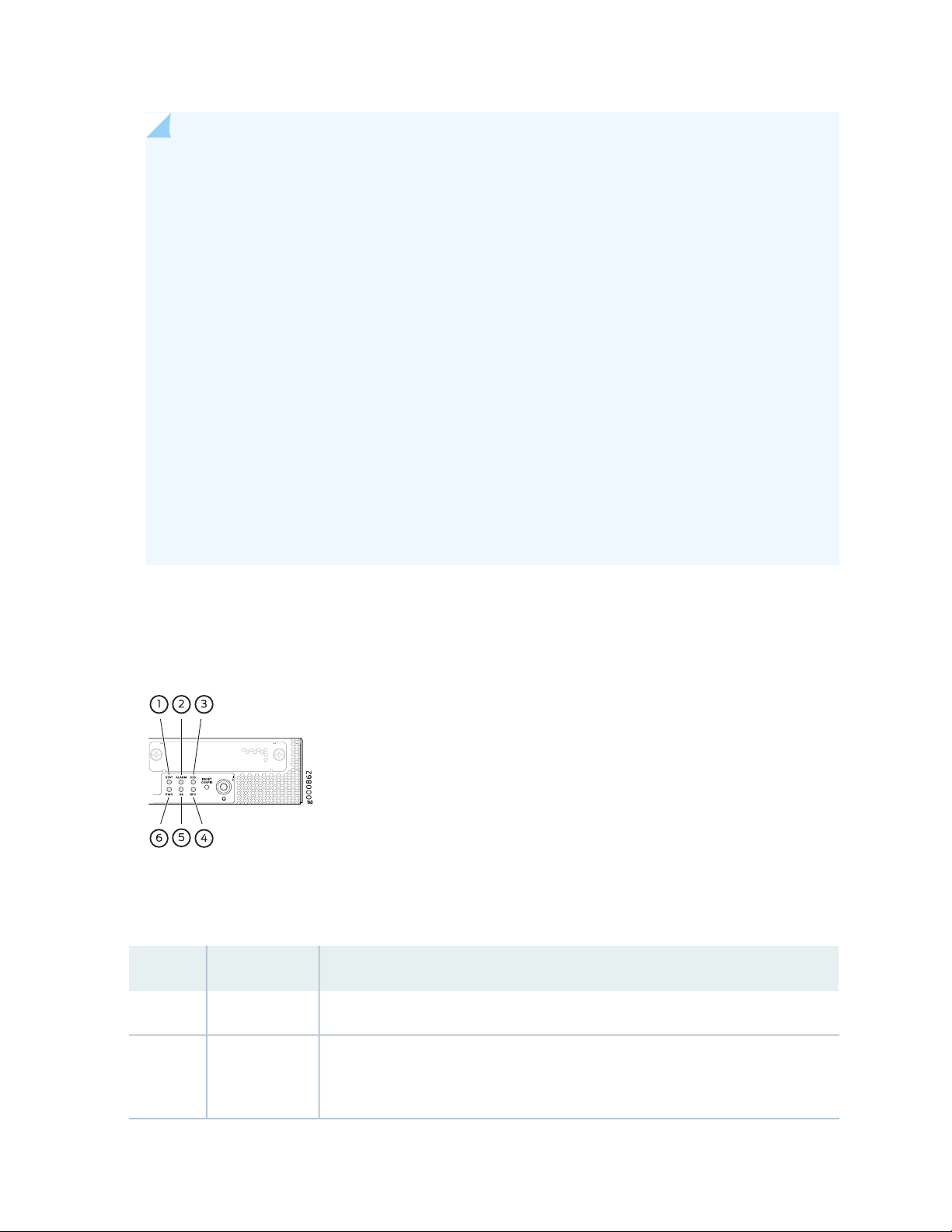
Figure 2 on page 21 shows the SRX1500 Services Gateway LEDs.
Figure 2: SRX1500 Services Gateway Front Panel LEDs
Table 4 on page 21 lists the SRX1500 Services Gateway LEDs.
Table 4: SRX1500 Services Gateway LEDs
DescriptionLEDCallout
Solid green—operating normallySTAT1
•
ALARM2
Solid amber—noncritical alarm
•
Solid red—critical alarm
•
Off—no alarms
•

Table 4: SRX1500 Services Gateway LEDs (continued)
DescriptionLEDCallout
22
SSD3
RPS4
HA5
PWR6
Management Port LEDs
Blinking green—the services gateway is transferring data to or from the SSD
•
storage device
Off—SSD storage device not present
•
Solid green—the redundant power supply is operating normally
•
Solid red—the redundant power supply is not operating normally
•
Off—no redundant power supply
•
Off—HA is disabled.
•
Solid green—all HA links are available.
•
Solid amber—some HA links are unavailable.
•
Solid red—device is inoperable due to a monitor failure
•
Solid green—receiving power
•
Blinking green—receiving power. The services gateway is in the bootup phase
•
before OS initialization.
Solid red—power supply unit failure
•
The management port has two LEDs that indicate link activity and status of the management port.
Table 5 on page 22 describes the LEDs.
Table 5: Management Port LEDs
DescriptionLED
Link (LED on the left)
Activity (LED on the
right)
Solid green—A link is established.
•
Off—There is no link established.
•
Blinking green—There is activity on the link.
•
Off—There is no link activity.
•
Network Port LEDs
The SFP and Ethernet ports have two status LEDs, LINK and ACT, located above the port.
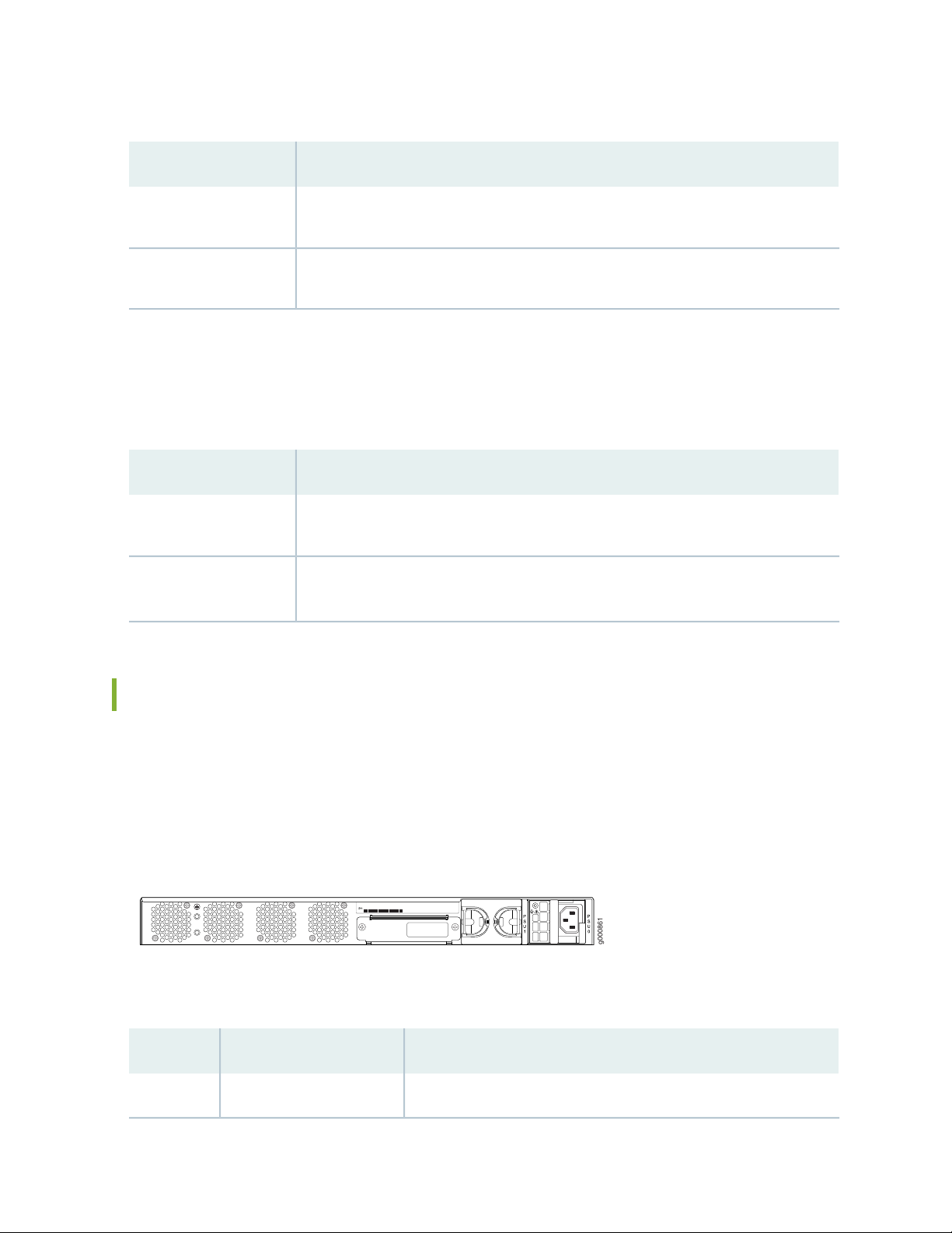
Table 6: Network Port LEDs
g000861
DescriptionLED
23
LINK (LED on the left)
ACT (LED on the right)
Solid green—A link is established.
•
Off—There is no link established.
•
Blinking green—There is activity on the 1 G link.
•
Off—There is no link activity.
•
HA Port LEDs
The HA port has two LEDs located above the port to indicate status.
Table 7: HA Port LEDs
DescriptionLED
Link (LED on the left)
Activity (LED on the
right)
Solid green—A link is established.
•
Off—There is no link established.
•
Blinking green—There is activity on the link.
•
Off—There is no link activity.
•
SRX1500 Services Gateway Back Panel
Figure 3 on page 23 shows the back panel of the SRX1500 Services Gateway and Table 8 on page 23 lists
the back panel components.
Figure 3: SRX1500 Services Gateway Back Panel
Table 8: SRX1500 Services Gateway Back Panel Components
DescriptionComponentCallout
Connects the services gateway chassis to earth ground.Grounding point1

Table 8: SRX1500 Services Gateway Back Panel Components (continued)
DescriptionComponentCallout
Contains the SSD storage device.SSD slot2
24
Power supply3
RELATED DOCUMENTATION
SRX1500 Services Gateway Installation Overview | 45
Two power supply slots. Each power supply contains a power cord
outlet. One 400 W AC or 650 W DC power supply is provided with
the services gateway.
Four fans for cooling the services gateway and its components.Fans4
SRX1500 Cooling System
The services gateway has a single fan tray that contains four fixed fans. The fan controller constantly
monitors the temperature of the services gateway and its components. Under normal operating conditions,
the fans function at lower than full speed.
If any one of the four fans fails, the services gateway generates a warning but keeps the system running.
If the temperature keeps rising, the services gateway lowers the power consumption by reducing the
performance or shutting down some of the chassis components. However, if the ambient maximum
temperature exceeds the warning level and the system cannot be adequately cooled, then the services
gateway shuts down the system and hardware components completely.
RELATED DOCUMENTATION
SRX1500 Services Gateway Clearance Requirements for Airflow and Hardware Maintenance | 37

SRX1500 Power System
IN THIS SECTION
SRX1500 Services Gateway Power Supply | 25
SRX1500 Services Gateway Supported AC Power Cords | 27
SRX1500 Services Gateway AC Power Supply Electrical Specifications | 28
SRX1500 Services Gateway DC Power Supply Electrical Specifications | 28
SRX1500 Services Gateway DC Power Cable Specifications | 29
SRX1500 Services Gateway Power Supply
25
The power supplies are located on the rear of the chassis. The SRX1500 Services Gateway uses either one
AC or one DC power supply unit.
A second AC or DC power supply can be used with its matching type of power supply to provide redundancy.
Each power supply provides power to all components in the services gateway. When two power supplies
are present, they share power almost equally within a fully populated system. The two power supplies
provide power redundancy. If one power supply fails or is removed, the remaining power supply redistributes
the electrical load without interruption. The services gateway reassesses the power required to support
its configuration and issues errors if the available power is insufficient.
Each power supply is cooled by its own internal cooling system.
NOTE: Only redundant power supplies (AC or DC) support hot-swappable functionality.
Figure 4 on page 26 shows the AC power supply.
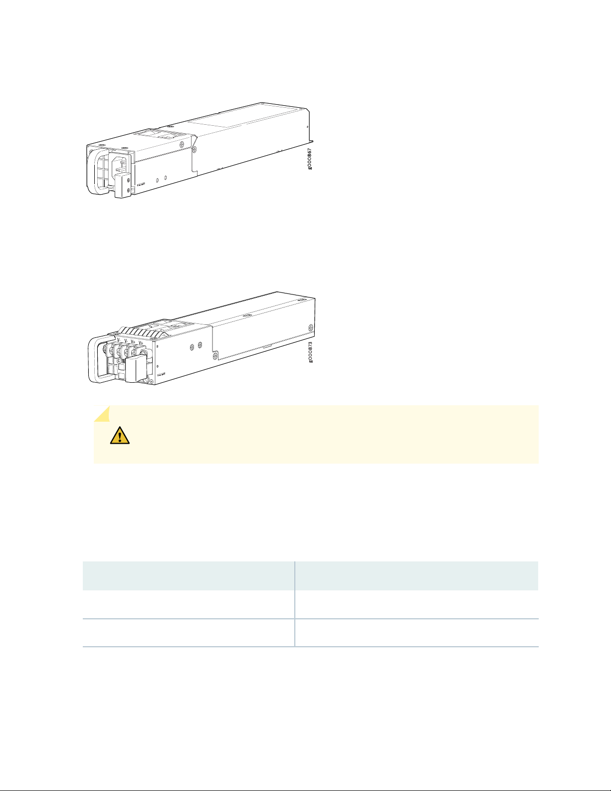
Figure 4: AC Power Supply for the SRX1500 Services Gateway
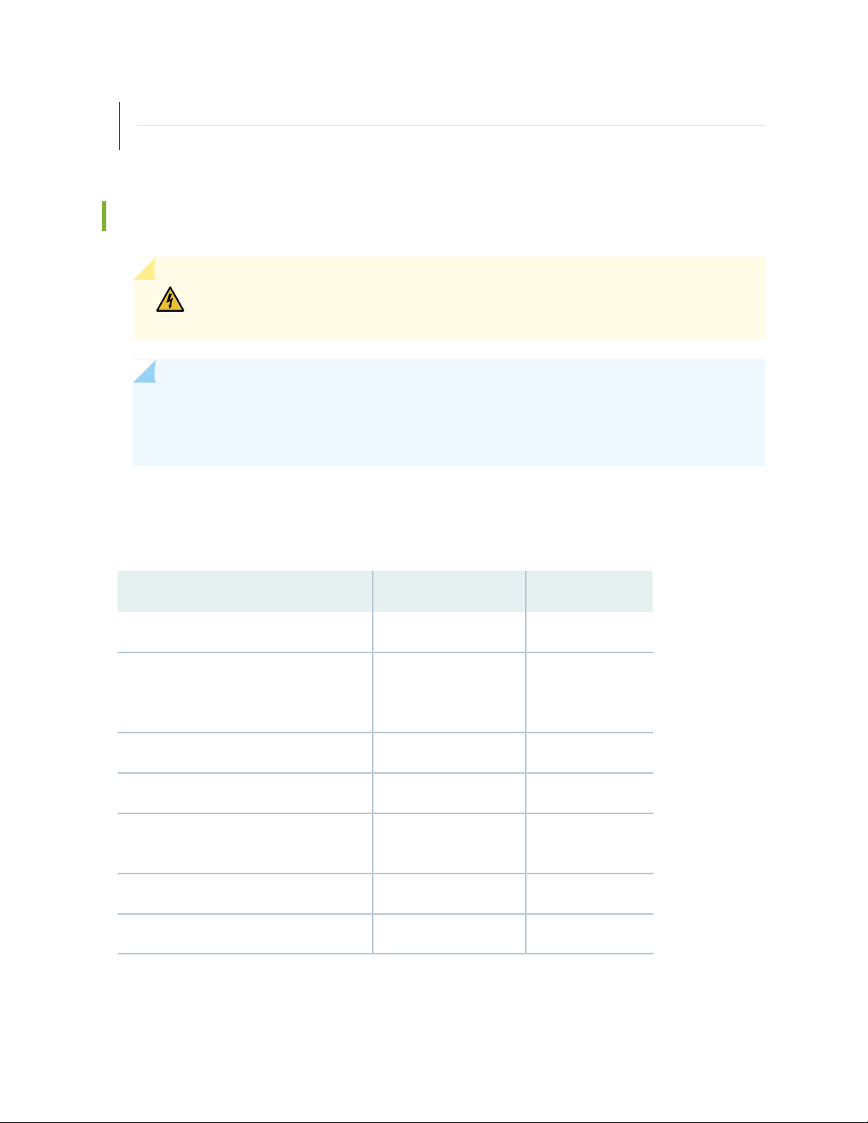
Figure 5 on page 26 shows the DC power supply.
Figure 5: DC Power Supply for the SRX1500 Services Gateway
26
CAUTION: Do not mix AC and DC power supplies within the same services gateway.
Damage to the device might occur.
The power supplies produce and distribute different output voltages to the services gateway components
according to their voltage requirements.
Table 9 on page 26 lists the power consumption values for the power supplies.
Table 9: Component Power Output/Consumption
Output/ConsumptionPower Supply
400 W @12 V400 W AC power supply
650 W @12 V650 W DC power supply
SEE ALSO
Powering On the SRX1500 Services Gateway | 58
Powering Off the SRX1500 Services Gateway | 59
SRX1500 Services Gateway Supported AC Power Cords
WARNING: The AC power cord for the services gateway is intended for use with the
services gateway only and not for any other use.
NOTE: In North America, AC power cords must not exceed 4.5 m (approximately 14.75 ft) in
length, to comply with National Electrical code (NEC) Section 400-8 (NFPA 75, 5-2.2) and 210-52,
and Canadian Electrical Code (CEC) Section 4-010(3).
27
Table 10 on page 27 provides power cord specifications, and Figure 6 on page 28 depicts the plug on the
AC power cord provided for each country or region.
Table 10: AC Power Cord Specifications
Plug StandardsElectrical SpecificationCountry
AS/NZ 3112-1993250 VAC, 10 A, 50 HzAustralia
250 VAC, 10 A, 50 HzChina
Japan
Hz
GB2099.1 1996 and
GB 1002 1996
(CH1-10P)
CEE (7) VII250 VAC, 10 A, 50 HzEurope (except Italy and United Kingdom)
CEI 23-16/VII250 VAC, 10 A, 50 HzItaly
JIS 8303125 VAC, 12 A, 50 or 60
NEMA 5-15125 VAC, 10 A, 60 HzNorth America
BS 1363A250 VAC, 10 A, 50 HzUnited Kingdom
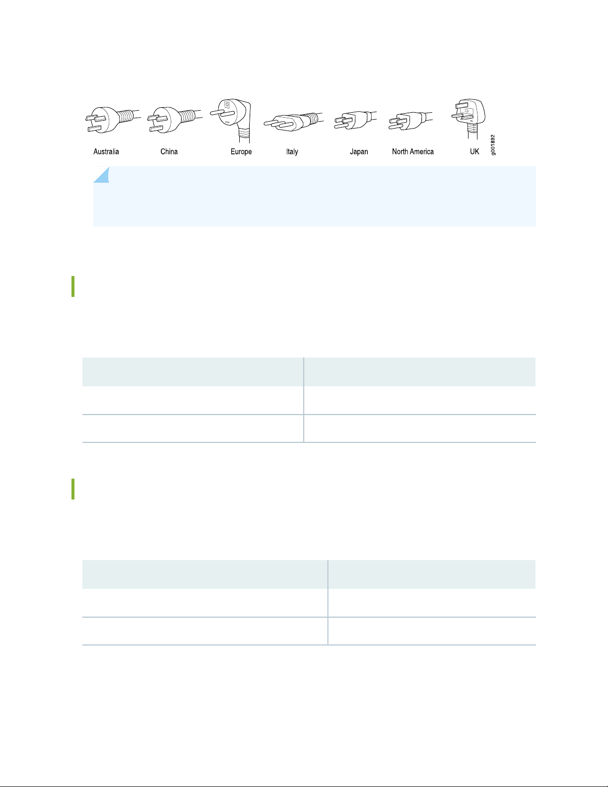
Figure 6: AC Plug Types
NOTE: Power cords and cables must not block access to services gateway components or drape
where people might trip on them.
SRX1500 Services Gateway AC Power Supply Electrical Specifications
Table 11 on page 28 lists the AC power supply electrical specifications for the SRX1500 Services Gateway.
28
Table 11: AC Power Supply Electrical Specifications for the SRX1500 Services Gateway
SpecificationPower Requirement
100 to 127 V ~ 2.5 A, 200 to 240 V ~ 1.3 AAC input voltage
47 to 63 HzAC input line frequency
SRX1500 Services Gateway DC Power Supply Electrical Specifications
Table 12 on page 28 lists the DC power supply electrical specifications for the SRX1500 Services Gateway.
Table 12: DC Power Supply Electrical Specifications for the SRX1500 Services Gateway
SpecificationPower Requirement
–44 to –72 VDCDC input voltage
6.2 A maximumDC system current rating
SRX1500 Services Gateway DC Power Cable Specifications
The DC power supply in slot 0 must be powered by dedicated power feeds derived from feed A, and the
DC power supply in slot 1 must be powered by dedicated power feeds derived from feed B. This
configuration provides the commonly deployed A/B feed redundancy for the system.
CAUTION: You must ensure that power connections maintain the proper polarity.
The power source cables might be labeled (+) and (–) to indicate their polarity. There
is no standard color coding for DC power cables. The color coding used by the external
DC power source at your site determines the color coding for the leads on the power
cables that attach to the terminal studs on each power supply.
WARNING: For field-wiring connections, use copper conductors only. For other
electrical safety information, see “SRX1500 Services Gateway Electrical Wiring
Guidelines” on page 34.
29
CAUTION: Power cords and cables must not block access to services gateway
components or drape where people could trip on them.
Table 13 on page 29 summarizes the specifications for the power cable(s), which you must supply.
Table 13: SRX1500 Services Gateway DC Power Cable Specification
Quantity and SpecificationCable Type
14-16 AWG, minimum 60° C wire, or as permitted by the local codePower
RELATED DOCUMENTATION
SRX1500 Services Gateway Electrical Wiring Guidelines | 34

2
CHAPTER
Site Planning, Preparation, and
Specifications
Site Preparation Checklist for the SRX1500 Services Gateway | 31
SRX1500 Site Guidelines and Requirements | 33
SRX1500 Transceiver Specifications and Pinouts | 40

Site Preparation Checklist for the SRX1500 Services Gateway
Table 14 on page 31 provides a checklist of tasks you need to perform when preparing a site for installing
the SRX1500 Services Gateway.
Table 14: Site Preparation Checklist for SRX1500 Services Gateway Installation
Performed
ByAdditional InformationItem or Task
Power
NotesDate
31
Measure distance between external power
sources and device installation site.
Locate sites for connection of system
grounding.
Calculate the power consumption and
requirements.
Environment
Verify that environmental factors such as
temperature and humidity do not exceed
device tolerances.
“SRX1500 Services Gateway
Electrical Wiring Guidelines” on
page 34
“Connecting the SRX1500 Services
Gateway Grounding Cable” on
page 50
“SRX1500 Services Gateway AC
Power Supply Electrical
Specifications” on page 28 and
“SRX1500 Services Gateway DC
Power Supply Electrical
Specifications” on page 28
“SRX1500 Services Gateway
Environmental Specifications” on
page 34
Rack Installation

Table 14: Site Preparation Checklist for SRX1500 Services Gateway Installation (continued)
Performed
ByAdditional InformationItem or Task
“Rack Requirements” on page 39Verify that your rack meets the minimum
requirements.
Plan rack location, including required space
clearances.
If a rack is used, secure the rack to the floor
and building structure.
Cabinet Installation
“Cabinet Requirements” on page 39Verify that your cabinet meets the
minimum requirements.
32
NotesDate
Plan the cabinet location, including required
space clearances.
Cables
Acquire cables and connectors.
Review the maximum distance allowed for
each cable. Choose the length of cable
based on the distance between the
hardware components being connected.
Plan the cable routing and management.
RELATED DOCUMENTATION
“SRX1500 Services Gateway
Supported AC Power Cords” on
page 27and “SRX1500 Services
Gateway DC Power Cable
Specifications” on page 29
SRX1500 Services Gateway Installation Overview | 45

SRX1500 Site Guidelines and Requirements
IN THIS SECTION
SRX1500 Services Gateway General Site Installation Guidelines | 33
SRX1500 Services Gateway Environmental Specifications | 34
SRX1500 Services Gateway Electrical Wiring Guidelines | 34
SRX1500 Services Gateway Grounding Specifications | 36
SRX1500 Services Gateway Physical Specifications | 36
SRX1500 Services Gateway Clearance Requirements for Airflow and Hardware Maintenance | 37
Rack Requirements | 39
Cabinet Requirements | 39
33
SRX1500 Services Gateway General Site Installation Guidelines
The following precautions help you plan an acceptable operating environment for your SRX1500 Services
Gateway and avoid environmentally caused equipment failures:
For the cooling system to function properly, the airflow around the chassis must be unrestricted. Allow
•
sufficient clearance between the front and back of the chassis and adjacent equipment. Ensure that
there is adequate circulation in the installation location.
Follow the ESD procedures to avoid damaging equipment. Static discharge can cause components to
•
fail completely or intermittently over time. For more information, see “Prevention of Electrostatic
Discharge Damage” on page 107.
Ensure that the blank panels are installed into empty slots to prevent any interruption or reduction in
•
the flow of air across internal components.
NOTE: Install the services gateway only in restricted areas, such as dedicated equipment rooms
and equipment closets, in accordance with Articles 110–16, 110–17, and 110–18 of the National
Electrical Code, ANSI/NFPA 70.

SRX1500 Services Gateway Environmental Specifications
Table 15 on page 34 provides the required environmental conditions for normal SRX1500 Services Gateway
operations. In addition, the site must be as dust-free as possible because dust can clog air intake vents,
reducing the efficiency of the cooling system.
Table 15: SRX1500 Services Gateway Environmental Specifications
ValueDescription
No performance degradation to 10,000 ft (3048 m)Altitude
34
Relative humidity
Temperature
Normal operation ensured in relative humidity range of 5% to 90%,
noncondensing
Normal operation ensured in temperature range of 32° F (0° C) to 104°
•
F (40° C)
Nonoperating storage temperature in shipping container: –40° F (–40°
•
C) to 158° F (70° C)
614 BTU/hourMaximum thermal output
512 BTU / hourAverage heat dissipation
66.5 dBANoise level
SRX1500 Services Gateway Electrical Wiring Guidelines
Table 16 on page 35 describes the factors you must consider while planning the electrical wiring for the
SRX1500 Services Gateway at your site.
CAUTION: It is particularly important to provide a properly grounded and shielded
environment and to use electrical surge-suppression devices.

Table 16: Site Electrical Wiring Guidelines for the SRX1500 Services Gateway
GuidelineSite Wiring Factor
35
Signaling limitations
Radio frequency
interference (RFI)
Electromagnetic
compatibility (EMC)
To ensure that signaling functions optimally:
Install wires correctly.
•
Improperly installed wires can emit radio interference.
Do not exceed the recommended distances or pass wires between buildings.
•
The potential for damage from lightning strikes increases if wires exceed recommended
distances or if wires pass between buildings.
Shield all conductors.
•
The electromagnetic pulse (EMP) caused by lightning can damage unshielded
conductors and destroy electronic devices.
To reduce or eliminate the emission of RFI from your site wiring:
Use twisted-pair cable with a good distribution of grounding conductors.
•
Use a high-quality twisted-pair cable with one ground conductor for each data signal
•
when applicable, if you must exceed the recommended distances.
Provide a properly grounded and shielded environment and use electrical
surge-suppression devices.
Strong sources of electromagnetic interference (EMI) can cause the following damage:
Destroy the signal drivers and receivers in the device
•
Conduct power surges over the lines into the equipment, resulting in an electrical
•
hazard
TIP: If your site is susceptible to problems with EMC, particularly from lightning or radio
transmitters, you might want to seek expert advice.
WARNING: Some ports are designed for use as intrabuilding interfaces only Type 2
or Type 4 ports, the battery return connection is to be treated as an Isolated DC return
(that is, DC-I), as defined in GR-1089-CORE and require isolation from the exposed
OSP cabling. To comply with NEBS requirements and protect against lightning surges
and commercial power disturbances, the intrabuilding port(s) of the device MUST NOT
be metallically connected to interfaces that connect to the OSP or its wiring. The
intrabuilding port(s) of the device is suitable for connection to intrabuilding or
unexposed wiring or cabling only. The addition of primary protectors is not sufficient
protection to connect these interfaces metallically to OSP wiring.

SRX1500 Services Gateway Grounding Specifications
To meet safety and electromagnetic interference (EMI) requirements and to ensure proper operation, the
SRX1500 Services Gateway must be adequately grounded before power is connected. You must provide
a grounding lug to connect the services gateway to earth ground.
WARNING: Before you connect power to the services gateway, a licensed electrician
must attach a cable lug to the grounding and power cables that you supply. A cable
with an incorrectly attached lug can damage the services gateway (for example, by
causing a short circuit).
The services gateway chassis has one grounding point on the back panel. The grounding point consists of
two threaded holes spaced 0.625 in. (15.86 mm) apart. The grounding point holes fit M5 screws.
Table 17 on page 36 lists the specifications of the grounding cable used with the device.
36
Table 17: Grounding Cable Specifications for the SRX1500 Services Gateway
SpecificationGrounding Requirement
14 AWG single-strand wire cableGrounding cable
Up to 25AAmperage of grounding cable
Ring-type, vinyl-insulated TV14-6R lug, or equivalentGrounding lug
SEE ALSO
Connecting the SRX1500 Services Gateway Grounding Cable | 50
Powering On the SRX1500 Services Gateway | 58
Powering Off the SRX1500 Services Gateway | 59
SRX1500 Services Gateway Physical Specifications
Table 18 on page 37 lists the physical specifications for the services gateway.

Table 18: Physical Specifications for the SRX1500 Services Gateway
ValuePhysical Specification of Chassis
1.75 in.Height
17.5 in.Width
18.2 in.Depth
15 lb.Weight
SEE ALSO
SRX1500 Services Gateway Overview | 16
SRX1500 Services Gateway Front Panel | 18
37
SRX1500 Services Gateway Back Panel | 23
SRX1500 Services Gateway Clearance Requirements for Airflow and Hardware Maintenance
When planning the installation site for the SRX1500 Services Gateway, you need to allow sufficient
clearance around the rack. Consider the following:
For the cooling system to function properly, the airflow around the chassis must be unrestricted. The
•
fan tray contains four fans and provides front-to-back chassis cooling. Figure 7 on page 38 shows the
direction of airflow through the chassis.
For service personnel to remove and install hardware components, there must be adequate space at the
•
front and back of the services gateway as indicated in Table 19 on page 38.
If you are mounting the services gateway in a rack with other equipment, ensure that the exhaust from
•
other equipment does not blow into the intake vents of the chassis.
Table 19 on page 38 provides information about the clearance requirements for maintaining optimum
airflow and the distances necessary to facilitate easy maintenance of the services gateway.

Table 19: Clearance Requirements for the SRX1500 Services Gateway
g000866
PortsFRUs
Top down view
Recommended
ClearanceLocation
Requirement for Clearance
38
8.7 in. (22 cm)Front of the chassis
17.4 in. (44.2 cm)Rear of the chassis
rack or cabinet edge
6.0 in. (15.24 cm)Between both sides of the chassis and
any non-heat-producing surface such
as a wall or cabinet side
Figure 7 on page 38 shows the airflow through the chassis.
Figure 7: Airflow Through the Chassis
Space for service personnel to remove and
install hardware components
Space for service personnel to remove and
install hardware components
Space for cable management and organization2.5 in. (6.35 cm)Between front-mounting flange and
Space for the cooling system to function
properly and to maintain unrestricted airflow
around the chassis

Rack Requirements
When installing the services gateway in a rack, you must ensure that the rack complies with a 1U (19 in.
or 48.7 cm) rack as defined in Cabinets, Racks, Panels, and Associated Equipment (document number
EIA-310-D), published by the Electronic Industries Alliance (http://www.ecaus.org/eia/site/index.html).
When selecting a rack, ensure that the physical characteristics of the rack comply with the following
specifications:
The outer edges of the mounting brackets extend the width of either chassis to 19 in. (48.3 cm).
•
The front of the chassis extends approximately 0.5 in. (1.27 cm) beyond the mounting ears.
•
Maximum permissible ambient temperature when two devices are placed side by side in a 19 in. rack is
•
40° C.
The spacing of the mounting brackets and flange holes on the rack and device mounting brackets are as
follows:
39
The holes within each rack set are spaced at 1 U (1.75 in. or 4.5 cm).
•
The mounting brackets and front-mount flanges used to attach the chassis to a rack are designed to
•
fasten to holes spaced at rack distances of 1 U (1.75 in.).
The mounting holes in the mounting brackets provided with the device are spaced 1.25 in. (3.2 cm) apart
•
(top and bottom mounting hole).
Always secure the rack in which you are installing the services gateway to the structure of the building. If
your geographical area is subject to earthquakes, bolt the rack to the floor. For maximum stability, also
secure the rack to ceiling brackets.
Cabinet Requirements
You can install the services gateway in a 19 in. (48.7 cm) cabinet as defined in Cabinets, Racks, Panels, and
Associated Equipment (document number EIA-310-D) published by the Electronic Industries Alliance
(http://www.ecaus.org/eia/site/index.html). You must mount the services gateway horizontally in the
cabinet using appropriate rack adapters.
When selecting a cabinet, ensure that it meets the following specifications:
The cabinet is at least 1U (3.50 in. or 8.89 cm) and can accommodate the services gateway.
•
The outer edges of the mounting brackets extend the width of either chassis to 19 in. (48.7 cm), and the
•
front of the chassis extends approximately 0.5 in. (1.27 cm) beyond the mounting brackets.
The minimum total clearance inside the cabinet is 30.7 in. (78 cm) between the inside of the front door
•
and the inside of the rear door.

NOTE: A cabinet larger than the minimum required provides better airflow and reduces the
chance of overheating.
When you mount the services gateway in a cabinet, you must ensure that ventilation through the cabinet
is sufficient to prevent overheating. Consider the following when planning for chassis cooling:
Ensure that the cool air supply you provide through the cabinet can adequately dissipate the thermal
•
output of the services gateway.
Install the services gateway as close as possible to the front of the cabinet so that the cable management
•
system clears the inside of the front door. Installing the chassis close to the front of the cabinet maximizes
the clearance in the rear of the cabinet for critical airflow.
Route and dress all cables to minimize the blockage of airflow to and from the chassis.
•
40
SRX1500 Transceiver Specifications and Pinouts
IN THIS SECTION
SRX1500 Transceiver Support | 40
RJ-45 Connector Pinouts for the SRX1500 Services Gateway Ethernet Port | 41
RJ-45 Connector Pinouts for the SRX1500 Services Gateway Console Port | 41
Mini-USB Connector Pinouts for the SRX1500 Services Gateway Console Port | 42
SRX1500 Transceiver Support
You can find information about the pluggable transceivers supported on your Juniper Networks device
by using the Hardware Compatibility Tool. In addition to transceiver and connector type, the optical and
cable characteristics—where applicable—are documented for each transceiver. The Hardware Compatibility
Tool enables you to search by product, displaying all the transceivers supported on that device, or category,
by interface speed or type. The list of supported transceivers for the SRX1500 is located at
https://apps.juniper.net/hct/product/#prd=SRX1500.

RJ-45 Connector Pinouts for the SRX1500 Services Gateway Ethernet Port
The port on the front panel labeled MGMT is an autosensing 10/100/1000-Mbps Ethernet RJ-45 receptacle
that accepts an Ethernet cable for connecting the services gateway to a management LAN (or other device
that supports out-of-band management). Table 20 on page 41 describes the RJ-45 connector pinouts for
the Ethernet port.
Table 20: RJ-45 Connector Pinouts for Services Gateway Ethernet Port
SignalPin
TX+1
TX-2
RX+3
Termination network4
41
Termination network5
RX-6
Termination network7
Termination network8
RJ-45 Connector Pinouts for the SRX1500 Services Gateway Console Port
The SRX1500 Services Gateway has two console ports: an RJ-45 Ethernet port and a mini-USB Type-B
port. The port on the front panel labeled CONSOLE is an asynchronous serial interface that accepts an
RJ-45 connector. Table 21 on page 41 describes the RJ-45 connector pinouts for the console port.
Table 21: RJ-45 Connector Pinouts for the Services Gateway Console Port
DescriptionSignalPin
Request to SendRTS1
Data Terminal ReadyDTR2
Transmit DataTXD3

Table 21: RJ-45 Connector Pinouts for the Services Gateway Console Port (continued)
DescriptionSignalPin
Signal GroundGround4
Signal GroundGround5
Receive DataRXD6
Data Set ReadyDSR/DCD7
Clear to SendCTS8
Mini-USB Connector Pinouts for the SRX1500 Services Gateway Console
42
Port
The SRX1500 Services Gateway has two console ports: an RJ-45 Ethernet port and a mini-USB Type-B
port. If your management device (laptop or PC) does not have a DB-9 plug connector pin or an RJ-45
connector pin, you can connect your management device to the Mini-USB Type-B console port of the
services gateway by using a cable that has a standard Type-A USB connector on one end and a Mini-USB
Type-B (5-pin) connector on the other end. Table 22 on page 42 describes the Mini-USB Type-B connector
pinouts for the console port.
NOTE: By design, the mini-USB console port has higher priority over the RJ-45 console port. If
both mini-USB and RJ-45 console ports are connected, then the mini-USB console port will be
active.
Table 22: Mini-USB Type-B Connector Pinouts for the Services Gateway Console Port
DescriptionCable ColorSignalPin
+5 VDCRedVCC1
Data -WhiteD-2
Data +GreenD+3

Table 22: Mini-USB Type-B Connector Pinouts for the Services Gateway Console Port (continued)
DescriptionCable ColorSignalPin
43
N/CX
RELATED DOCUMENTATION
SRX1500 Services Gateway Front Panel | 18
Could be not connected
(N/C), connected to
ground (GND), or used as
an attached device
presence indicator
GroundBlackGND4

3
CHAPTER
Initial Installation and Configuration
SRX1500 Services Gateway Installation Overview | 45
Unpacking and Mounting the SRX1500 | 45
Connecting the SRX1500 to Power | 50
Connecting the SRX1500 to External Devices | 60
Configuring Junos OS on the SRX1500 | 62

SRX1500 Services Gateway Installation Overview
After you have prepared the site for installation and unpacked the SRX1500 Services Gateway, you are
ready to install the device. It is important to proceed through the installation process in the following order:
1. Review the safety guidelines explained in “General Electrical Safety Guidelines and Warnings” on
page 123.
2. Prepare the services gateway for installation as described in “Preparing the SRX1500 Services Gateway
for Rack-Mount Installation” on page 48.
3. Install the services gateway as described in “Installing the SRX1500 Services Gateway in a Rack” on
page 48.
4. Connect cables to external devices as described in “Connecting the SRX1500 Services Gateway to a
Network for Out-of-Band Management” on page 60 and “Connecting the SRX1500 Services Gateway
to a Management Console” on page 61.
45
5. Connect the grounding cable as described in “Connecting the SRX1500 Services Gateway Grounding
Cable” on page 50.
6. Power on the services gateway as described in “Powering On the SRX1500 Services Gateway” on
page 58.
Unpacking and Mounting the SRX1500
IN THIS SECTION
Unpacking the SRX1500 Services Gateway | 46
Verifying Parts Received with the SRX1500 Services Gateway | 46
Preparing the SRX1500 Services Gateway for Rack-Mount Installation | 48
Installing the SRX1500 Services Gateway in a Rack | 48

Unpacking the SRX1500 Services Gateway
The SRX1500 Services Gateway is shipped in a cardboard carton and secured with foam packing material.
The carton also contains an accessory box and quick-start instructions.
NOTE: The services gateway is maximally protected inside the cardboard carton. Do not unpack
it until you are ready to begin installation.
To unpack the SRX1500 Services Gateway:
1. Move the cardboard carton to a staging area as close to the installation site as possible, where you
have enough room to remove the components from the chassis.
2. Position the cardboard carton with the arrows pointing up.
46
3. Carefully open the top of the cardboard carton.
4. Remove the foam covering the top of the services gateway.
5. Remove the accessory box.
6. Verify the parts received against the lists in “Verifying Parts Received with the SRX1500 Services
Gateway” on page 46.
7. Store the brackets and bolts inside the accessory box.
8. Save the shipping carton and packing materials in case you need to move or ship the services gateway
at a later time.
Verifying Parts Received with the SRX1500 Services Gateway
The SRX1500 Services Gateway shipment package contains a packing list. Check the parts in the shipment
against the items on the packing list. The packing list specifies the part numbers and carries a brief
description of each part in your order.
If any part is missing, contact a customer service representative.

A fully configured services gateway contains the chassis with installed components, listed in
Table 23 on page 47, and an accessory box, which contains the parts listed in Table 24 on page 47.
NOTE: The parts shipped with your services gateway can vary depending on the configuration
you ordered.
Table 23: Parts List for a Fully Configured SRX1500 Services Gateway
QuantityComponent
11U SRX1500 Services Gateway chassis with 12 Gigabit Ethernet LAN ports, four 1G SFP ports,
four 1G/10G SFP ports, two power supply slots, four fans, and one SSD (includes blank covers
for WAN PIM)
1Front-mount rack-mount kit
47
NOTE: The shipment includes one power cord appropriate for your geographical location.
Two power supplies must be installed in the services gateway for redundancy.
Table 24: Accessory/Upgrade Parts List for the SRX1500 Services Gateway
QuantityPart
1RoHS Card
1End User License Agreement
1CAT5E cable
1DB9-to-RJ45 adapter
1USB cable
1Documentation Roadmap and Product Warranty
1400 W AC or 650 W DC power supply

Preparing the SRX1500 Services Gateway for Rack-Mount Installation
You can mount an SRX1500 Services Gateway on four-post (telco) racks, enclosed cabinets, and open-frame
racks. Center-mount racks are not supported.
Before mounting the SRX1500 Services Gateway in a rack:
Verify that the site meets the requirements described in “Site Preparation Checklist for the SRX1500
•
Services Gateway” on page 31.
Verify that you have the following parts available in your rack-mounting kit for the SRX1500 Services
•
Gateway:
Rack-mounting brackets
•
Screws
•
Verify that the racks or cabinets meet the specific requirements described in SRX1500 Services Gateway
•
Rack Requirements.
48
Place the rack or cabinet in its permanent location, allowing adequate clearance for airflow and
•
maintenance, and secure it to the building structure. For more information, see “Cabinet Requirements”
on page 39.
Remove the gateway chassis from the shipping carton. For unpacking instructions, see “Unpacking the
•
SRX1500 Services Gateway” on page 46.
Installing the SRX1500 Services Gateway in a Rack
You can front-mount the SRX1500 Services Gateway in a rack. Many types of racks are acceptable, including
four-post (telco) racks, enclosed cabinets, and open-frame racks.
NOTE: If you are installing multiple devices in one rack, install the lowest one first and proceed
upward in the rack.
To install the services gateway in a rack:
1. Position a mounting bracket on each side of the chassis.
2. Use a number 2 Phillips screwdriver to install the screws that secure the mounting brackets to the
chassis.

Figure 8: Installing the Mounting Brackets on the SRX1500 Services Gateway
g000872
3. Have one person grasp the sides of the services gateway, lift it, and position it in the rack.
4. Align the bottom hole in each mounting bracket with a hole in each rack rail, making sure the chassis
is level.
5. Have a second person install a mounting screw into each of the two aligned holes. Use a number 2
Phillips screwdriver to tighten the screws.
49
6. Install the second screw in each mounting bracket.
Figure 9: Installing the SRX1500 Services Gateway in a Rack
7. Verify that the mounting screws on one side of the rack are aligned with the mounting screws on the
opposite side and that the services gateway is level.

Connecting the SRX1500 to Power
IN THIS SECTION
Required Tools and Parts for Grounding the SRX1500 Services Gateway | 50
Connecting the SRX1500 Services Gateway Grounding Cable | 50
Installing an AC Power Supply on the SRX1500 Services Gateway | 52
Connecting the SRX1500 Services Gateway to an AC Power Supply | 53
Installing a DC Power Supply on the SRX1500 Services Gateway | 54
Connecting the SRX1500 Services Gateway to a DC Power Supply | 57
Powering On the SRX1500 Services Gateway | 58
Powering Off the SRX1500 Services Gateway | 59
50
Required Tools and Parts for Grounding the SRX1500 Services Gateway
To ground and to provide power to the services gateway, you need the following tools:
Phillips (+) screwdrivers, numbers 1 and 2
•
Electrostatic discharge (ESD) grounding wrist strap
•
Wire cutters
•
Connecting the SRX1500 Services Gateway Grounding Cable
You ground the services gateway by connecting a grounding cable to earth ground and then attaching it
to the chassis grounding points located on the back panel of the device using two metric M5 x 0.8,
12-mm-long grounding screws.
You must provide the following items:
Two metric M5 x 0.8, 12-mm-long grounding screws
•
Grounding cables
•
Cable lugs (for example, Panduit LCC6-10A-L)
•

CAUTION: Before you connect power to the services gateway, a licensed electrician
must attach a cable lug to the grounding and power cables that you supply. A cable
with an incorrectly attached lug can damage the services gateway (for example, by
causing a short circuit).
To ground the services gateway:
1. Attach an electrostatic discharge (ESD) grounding strap to your bare wrist, and connect the strap to
the ESD point on the chassis. For more details, see “Prevention of Electrostatic Discharge Damage” on
page 107.
2. Ensure that all grounding surfaces are clean and brought to a bright finish before grounding connections
are made.
3. Connect the grounding cable to a proper earth ground.
51
4. Place the grounding cable lugs over the grounding points (sized for metric M5 x 0.8, 12-mm-long
grounding screws) on the side of the chassis.
Figure 10: Connecting the Grounding Cable to the SRX1500 Services Gateway
5. Secure the grounding cable lugs to the grounding points, first with the washers, then with the screws.
6. Dress the grounding cable and verify that it does not touch or block access to the services gateway
components and that it does not drape where people could trip on it.

Installing an AC Power Supply on the SRX1500 Services Gateway
To install an AC power supply:
1. Attach an electrostatic discharge (ESD) grounding strap to your bare wrist and connect the strap to
one of the ESD points on the chassis. For more information about ESD, see “Prevention of Electrostatic
Discharge Damage” on page 107.
2. Using both hands, slide the power supply straight into the chassis until the power supply is fully seated
in the chassis slot. The power supply faceplate should be flush with any adjacent power supply faceplate
(see Figure 11 on page 52).
Figure 11: Installing an AC Power Supply on the SRX1500 Services Gateway
52
3. Attach the power cord to the power supply. Use a power cord retainer to hold the power cord in place.
Figure 12: Connecting the AC Power Cord on the SRX1500 Services Gateway
4. Attach the power cord to the AC power source, and switch on the dedicated facility circuit breaker for
the power supply. Follow the ESD and connection instructions for your site. If the power supply is
correctly installed and functioning normally, the PWR LED glows steadily.

NOTE: If more than one power supply is being installed, ensure the following:
Connect power cords to both the power supplies.
•
Connect each power supply to a DC power feed.
•
If both power supplies are plugged in and receiving power, the RPS LED glows solid green.
Connecting the SRX1500 Services Gateway to an AC Power Supply
CAUTION: Do not mix AC and DC power supplies within the same services gateway.
Damage to the device might occur.
53
You connect AC power to the services gateway by attaching the power cord from the AC power source
to the AC appliance inlet located on the power supply.
To connect the services gateway to an AC power supply:
1. Attach an electrostatic discharge (ESD) grounding strap to your bare wrist, and connect the strap to
the ESD point on the front of the chassis.
2. Insert the appliance coupler end of the power cord into the appliance inlet on the power supply.
3. Insert the power cord plug into an external AC power source receptacle.
NOTE: Each power supply must be connected to a dedicated AC power feed and a dedicated
external circuit breaker. We recommend that you use a 15 A (250 VAC) minimum, or as
permitted by local code.
4. Dress the power cord appropriately. Verify that the power cord does not block the air exhaust and
access to services gateway components or drape where people could trip on it.

NOTE: The services gateway must be connected to earth ground during normal operation. The
protective earthing terminal on the side of the chassis is provided to connect the services gateway
to ground.
CAUTION: We recommend using a surge protector for the power connection.
Installing a DC Power Supply on the SRX1500 Services Gateway
To install a DC power supply:
54
1. Ensure that the voltage across the DC power source cable leads is 0 V and that there is no chance that
the cable leads might become active during installation. To ensure that all power is off, locate the circuit
breaker on the panel board that services the DC circuit, switch the circuit breaker to the OFF position
(O), and tape the switch handle of the circuit breaker in the OFF position.
2. Attach an electrostatic discharge (ESD) grounding strap to your bare wrist and connect the strap to
one of the ESD points on the chassis. For more information about ESD, see “Prevention of Electrostatic
Discharge Damage” on page 107.
3. Orient the power supply so that the locking lever is on the left as shown in Figure 13 on page 54.
Figure 13: Installing a DC Power Supply on an SRX1500 Services Gateway
4. Using both hands, slide the power supply straight into the chassis until the power supply is fully seated
in the chassis slot. The power supply faceplate should be flush with any adjacent power supply faceplate.

5. Tighten the captive screws on the lower edge of the power supply faceplate.
6. Remove the clear plastic cover protecting the terminal studs on the faceplate.
7. Verify that the DC power cables are correctly labeled before making connections to the power supply.
In a typical power distribution scheme where the return is connected to chassis ground at the battery
plant, you can use a multimeter to verify the ohm output of the –48V and RTN DC cables to chassis
ground. The cable with very large resistance (indicating an open circuit) to chassis ground will be –48V
and the cable with very low resistance (indicating a closed circuit) to chassis ground will be RTN.
CAUTION: You must ensure that power connections maintain the proper polarity.
The power source cables might be labeled (+) and (–) to indicate their polarity. There
is no standard color coding for DC power cables. The color coding used by the
external DC power source at your site determines the color coding for the leads
on the power cables that attach to the terminal studs on each power supply.
55
8. Using a number 2 Phillips screwdriver, remove the screws and square washers from the terminal studs.
9. Secure each power cable lug to the terminal studs, first with the square washer, then with the screw.
Apply between 23 lb-in. (2.6 Nm) and 25 lb-in. (2.8 Nm) of torque to each screw.
a. Attach the positive (+) DC source power cable lug to the RTN (return) terminal.
b. Attach the negative (–) DC source power cable lug to the –48V (input) terminal.
Figure 14: Securing the Power Cables
10. Replace the clear plastic cover over the terminal studs on the faceplate.

11. Verify that the power cables are connected correctly, that they are not touching or blocking access to
services gateway components, and that they do not drape where people could trip on them.
12. Remove the tape from the switch handle of the circuit breaker on the panel board that services the
DC circuit and switch the circuit breaker to the ON position (|). Observe the status LEDs on the power
supply faceplate. If the power supply is correctly installed and functioning normally, the POWER LED
glows solid green on the services gateway front panel.
NOTE: If more than one power supply is being installed, turn on all power supplies at the same
time.
If both power supplies are plugged in and receiving AC power, the RPS LED glows solid green.
56

Connecting the SRX1500 Services Gateway to a DC Power Supply
You connect DC power to the services gateway by attaching power cables from the external DC power
sources to the terminal studs on the power supply faceplates.
WARNING: To meet safety and electromagnetic interference (EMI) requirements and
to ensure proper operation, you must properly ground the services gateway chassis
before connecting power. See “Connecting the SRX1500 Services Gateway Grounding
Cable” on page 50 for instructions.
WARNING: Before performing the following procedure, ensure that power is removed
from the DC circuit. To ensure that all power is off, locate the circuit breaker on the
panel board that services the DC circuit, switch the circuit breaker to the OFF position
(0), and tape the switch handle of the circuit breaker in the OFF position.
57
CAUTION: Do not mix AC and DC power supplies within the same services gateway.
Damage to the services gateway might occur.
CAUTION: Before you connect power to the services gateway, a licensed electrician
must attach appropriate cable lugs to the grounding and power cables that you use.
A cable with an incorrectly attached lug can damage the device (for example, by causing
a short circuit).
To connect the DC source power cables to the services gateway for each power supply:
1. Switch off the dedicated facility circuit breakers. Ensure that the voltage across the DC power source
cable leads is 0 V and that there is no chance that the cable leads might become active during installation.
2. Remove the clear plastic cover that protects the terminal studs on the faceplate.
3. Verify that the DC power cables are correctly labeled before making connections to the power supply.
In a typical power distribution scheme where the return is connected to chassis ground at the battery
plant, you can use a multimeter to verify the ohm output of the -48V and RTN DC cables to chassis
ground. The cable with very large resistance (indicating an open circuit) to chassis ground will be -48V,
and the cable with very low resistance (indicating a closed circuit) to chassis ground will be RTN.

CAUTION: You must ensure that power connections maintain the proper polarity.
The power source cables might be labeled (+) and (–) to indicate their polarity. There
is no standard color coding for DC power cables. The color coding used by the
external DC power source at your site determines the color coding for the leads
on the power cables that attach to the terminal studs on each power supply.
4. Remove the screws and square washers from the terminals, using a Phillips (+) screwdriver, number 2.
5. Secure each power cable lug to the terminals with the square washers and the screws. Apply between
23 in.-lb (2.6 Nm) and 25 in.-lb (2.8 Nm) of torque to each screw.
Secure each positive (+) DC source power cable lug to a RTN (return) terminal.
•
Secure each negative (–) DC source power cable lug to a -48V (input) terminal.
•
6. Replace the clear plastic cover over the terminal studs on the faceplate.
58
7. Verify that the power cables are connected correctly, that they are not touching or blocking access to
services gateway components, and they do not cause a tripping hazard.
8. Repeat Steps 1 through 7 for the second power supply, if you are installing one.
NOTE: If power is lost to the services gateway, the Power-On/Power-Off state is retained. For
example, if the services gateway loses power while the device is on, when power returns, the
device will still be in the On state.
Powering On the SRX1500 Services Gateway
To power on the services gateway:
1. Ensure that you have connected the power supply to the device.
2. Insert the plug of the power supply adapter into an AC or DC power source receptacle.
a. Using AC power supply—Insert the appliance coupler end of the power cord into the appliance inlet
on the power supply and the power cord plug into an external AC power source receptacle.

b. Using DC power supply—Connect DC power cables to the A+ and A- terminals and the other ends
to an external DC power source. If you have two DC power sources and wish to deploy A/B feed
redundancy for the services gateway, also connect DC power cables to the B+ and B- terminals and
the other ends to an external DC power source.
CAUTION: You must ensure that power connections maintain the proper
polarity. The power source cables might be labeled (+) and (–) to indicate their
polarity. There is no standard color coding for DC power cables. The color coding
used by the external DC power source at your site determines the color coding
for the leads on the power cables that attach to the terminals on the power
supply.
3. Turn on the power to the AC or DC power receptacle.
The device starts automatically as the power supply completes its startup sequence. The PWR LED (on
the front panel of the chassis) lights up during startup and remains solid when the services gateway is
operating normally.
59
Powering Off the SRX1500 Services Gateway
To power off the device, press the Power button on the front of the device and hold it for 10 seconds. To
remove power completely from the services gateway, unplug the AC power cord or DC power supply
cable.
NOTE: Graceful shutdown is not supported on the SRX1500 Services Gateway.
After powering off a power supply, wait at least 60 seconds before turning it back on. After powering on
a power supply, wait at least 10 seconds before turning it off.
When the system is completely powered off and you turn on the power supply, the services gateway starts
as the power supply completes its startup sequence. If the services gateway finishes starting and you need
to power off the system again, first issue the request system halt command.
NOTE: The fans in the power supply continue to rotate even after you power off the SRX1500
Services Gateway. To stop the fans, remove the power cord from the power supply. The fans
stop in a few seconds.

After a power supply is turned on, it can take up to 60 seconds for status indicators—such as the POWER
LED (on the front panel of the chassis) and the show chassis command display—to indicate that the power
supply is functioning normally. Ignore error indicators that appear during the first 60 seconds.
Connecting the SRX1500 to External Devices
IN THIS SECTION
Required Tools and Parts for Connecting the SRX1500 Services Gateway | 60
Connecting the SRX1500 Services Gateway to a Network for Out-of-Band Management | 60
Connecting the SRX1500 Services Gateway to a Management Console | 61
60
Required Tools and Parts for Connecting the SRX1500 Services Gateway
To connect the services gateway, you need the following tools and parts:
Electrostatic discharge (ESD) grounding wrist strap
•
Phillips (+) screwdrivers, numbers 1 and 2
•
2.5-mm flat-blade (-) screwdriver
•
Connecting the SRX1500 Services Gateway to a Network for Out-of-Band Management
Use the MGMT port on the services gateway to connect to a network for out-of-band management.
To connect the management device to the SRX1500 Services Gateway:
1. Attach an electrostatic discharge (ESD) grounding strap to your bare wrist, and connect the strap to
one of the ESD points on the chassis.
2. Plug one end of the Ethernet cable into the MGMT port as shown in Figure 15 on page 61.

Figure 15: Connecting the SRX1500 Services Gateway to a Network for Out-of-Band Management
g000863
1
2
3
g000864
1
2
3
3. Plug the other end of the cable into the management device.
61
Connecting the SRX1500 Services Gateway to a Management Console
Use the CONSOLE port on the services gateway to connect to a management console.
To connect the SRX1500 Services Gateway to a management console, use an RJ-45 cable:
1. Attach an electrostatic discharge (ESD) grounding strap to your bare wrist, and connect the strap to
one of the ESD points on the chassis.
2. Plug the RJ-45 end of the cable into the CONSOLE port on the SRX1500 Services Gateway as shown
in Figure 16 on page 61.
Figure 16: Connecting the SRX1500 Services Gateway to a Management Console

3. Connect the other end of the Ethernet cable to the Ethernet port on the management device.
If the management device has a serial port, use the RJ-45 to DB-9 serial port adapter supplied with
your services gateway. Use the following values to configure the serial port:
Baud rate—9600
•
Parity—N
•
Data bits—8
•
Stop bits—1
•
Flow control—none
•
NOTE: Alternately, you can use the USB cable to connect to the mini-USB console port on
the services gateway. To use the USB console port, you must download a USB driver to the
management device from the Silicon Labs page.
62
Configuring Junos OS on the SRX1500
IN THIS SECTION
SRX1500 Services Gateway Software Configuration Overview | 63
Understanding SRX1500 Services Gateway Factory-Default Settings | 63
Viewing SRX1500 Services Gateway Factory-Default Settings | 63
Accessing J-Web on the SRX1500 Services Gateway | 64
Configuring the SRX1500 Services Gateway Using J-Web | 64
Accessing the CLI on the SRX1500 Services Gateway | 69
Connecting to the SRX1500 Services Gateway from the CLI Remotely | 70
Configuring the SRX1500 Services Gateway Using the CLI | 70

SRX1500 Services Gateway Software Configuration Overview
The SRX1500 Services Gateway is shipped with Junos OS preinstalled and ready to be configured when
the services gateway is powered on. If you are setting up the services gateway for the first time, use the
command-line interface (CLI) to perform the initial configuration.
Gather the following information before configuring the services gateway:
Root authentication
•
IP address of the management interface
•
Default route
•
Understanding SRX1500 Services Gateway Factory-Default Settings
63
Your services gateway comes configured with a factory-default configuration. The default configuration
includes the following security configuration:
Two security zones are created: trust and untrust.
•
Interface ge-0/0/0 is in the untrust zone, while interfaces ge-0/0/1 through ge-0/0/3 are in the trust
•
zone.
A security policy is created that permits outbound traffic from the trust zone to the untrust zone.
•
Source Network Address Translation (NAT) is configured on the trust zone.
•
If the current active configuration fails, you can use the load factory-default command to revert to the
factory-default configuration.
Viewing SRX1500 Services Gateway Factory-Default Settings
To view the factory-default configuration of the services gateway using the CLI:
1. Log in as the root user and provide your credentials.
2. View the list of default config files:
root@srx1500>file list /etc/config
3. View the required default config file.

root@srx1500> file show /etc/config/<config file name>
Accessing J-Web on the SRX1500 Services Gateway
The J-Web interface is a Web-based graphical interface that allows you to operate a services gateway
without commands. Before you can use J-Web to configure your device, you must access the CLI to
perform the initial configuration.
NOTE: To access the J-Web interface, your management device requires one of the following
supported browsers:
Microsoft Internet Explorer version 8.0, 9.0, or 10.0
•
Mozilla Firefox version 23+
•
64
Google Chrome version 28+
•
To access J-Web:
1. Open a Web browser on the management device and enter the device management IP address in the
address field.
2. Specify the default username as root and enter the password.
Configuring the SRX1500 Services Gateway Using J-Web
IN THIS SECTION
Configuring Root Authentication and the Management Interface from the CLI | 65
Configuring Interfaces, Zones, and Policies with J-Web | 66

Configuring Root Authentication and the Management Interface from the CLI
Before you can use J-Web to configure your device, you must access the CLI to perform the initial
configuration.
To configure root authentication and the management interface:
1. Log in as root. There is no password.
2. Start the CLI and enter configuration mode.
root@% cli
root@>configure
root@#
3. Set the root authentication password by entering a cleartext password, an encrypted password, or an
SSH public key string (DSA or RSA).
65
[edit]
root@# set system root-authentication plain-text-password
New password: password
Retype new password: password
4. Commit the configuration to activate it on the device.
[edit]
root@# commit
5. Configure the IP address and prefix length for the Ethernet management interface on the device.
[edit]
root@# set interfaces fxp0 unit 0 family inet address address/prefix-length
6. Configure the default route.
[edit]
root@# set routing-options static route 0.0.0.0/0 next-hop gateway
7. Enable Web access to launch J-Web.

[edit]
root@# set system services web-management http
8. Commit the configuration changes.
[edit]
root@# commit
Configuring Interfaces, Zones, and Policies with J-Web
IN THIS SECTION
Configuring the Hostname | 66
Configuring Interfaces | 67
66
Configuring Zones and Assigning Interfaces | 68
Configuring Security Policies | 68
You can configure hostnames, interfaces, zones, and security policies using J-Web.
Before you begin:
Ensure you have configured the IP address, root authentication, and default route. See “Configuring
•
Root Authentication and the Management Interface from the CLI” on page 65.
Enable HTTP on the device to access J-Web. See “Configuring Root Authentication and the Management
•
Interface from the CLI” on page 65.
Configure the device with J-Web using the following procedures.
Configuring the Hostname
To configure the hostname:
1. Launch a Web browser from the management device.
2. Enter the IP address of the device in the URL address field.
3. Specify the default username as root and enter the password. See “Configuring Root Authentication
and the Management Interface from the CLI” on page 65.

4. Click Log In. The J-Web Dashboard page appears.
5. Select Configure>System Properties>System Identity, and then select Edit. The Edit System Identity
dialog box appears.
6. Enter the hostname and click OK.
7. Select Commit Options>Commit to apply the configuration changes.
You have successfully configured the hostname for the system.
Configuring Interfaces
To configure two physical interfaces:
1. From the J-Web Dashboard page, select Configure>Interfaces and select a physical interface you want
to configure.
67
2. Select Add>Logical Interface. The Add interface dialog box appears.
3. Set Unit = 0.
4. Select the check box for IPv4 Address to enable IPv4 addressing.
5. Click Add and enter the IPv4 address.
6. Click OK.
A message appears after your configuration changes are validated successfully.
7. Click OK.
8. Select Commit Options>Commit to apply the configuration changes.
A message appears after your configuration changes are applied successfully.
9. Click OK.
You have successfully configured the physical interface. Repeat these steps to configure the second
physical interface for the device.

Configuring Zones and Assigning Interfaces
To assign interfaces within a trust zone and an untrust zone:
1. From the J-Web Dashboard page, select Configure>Security>Zones/Screens and click Add. The Add
Zone dialog box appears.
2. In the Main tab, enter trust for zone name and enter the description.
3. Set the zone type to Security.
4. Select the interfaces listed under Available and move them under Selected.
5. Click OK.
A message appears after your configuration changes are validated successfully.
6. Click OK.
68
7. Select Commit Options>Commit to apply the configuration changes.
A message appears after your configuration changes are applied successfully.
8. Click OK.
9. Repeat Step 1 through Step 8 and assign another interface to an untrust zone.
You have successfully configured interfaces in a trust zone and in an untrust zone.
Configuring Security Policies
To configure security policies:
1. From the J-Web Dashboard page, select Configure>Security>Security Policy and click Add. The Add
Policy dialog box appears.
2. In the Policy tab, enter the policy name and set the policy action to permit. Then select Zone and set
the From Zone to trust and the To Zone to untrust.
3. Configure the source IP address by selecting any listed under Available and moving it under Selected.
4. Configure the destination IP address by selecting any listed under Available and moving it under Selected.
5. Configure the application by selecting any listed under Available and moving it under Selected.

6. Click OK.
A message appears after your configuration changes are validated successfully.
7. Click OK.
8. Select Commit Options>Commit to apply the configuration changes.
A message appears after your configuration changes are applied successfully.
9. Click OK.
You have successfully configured the security policy.
Accessing the CLI on the SRX1500 Services Gateway
69
To access the CLI on the SRX1500 Services Gateway:
1. Plug one end of the Ethernet cable into the RJ-45 to DB-9 serial port adapter supplied with your services
gateway.
2. Plug the RJ-45 to DB-9 serial port adapter into the serial port on the management device.
3. Connect the other end of the Ethernet cable to the serial console port on the services gateway.
NOTE: Alternately, you can use the USB cable to connect to the mini-USB console port on
the services gateway. To use the USB console port, you must download a USB driver to the
management device from the Silicon Labs page.
4. Start your asynchronous terminal emulation application (such as Microsoft Windows HyperTerminal)
and select the appropriate COM port to use (for example, COM1).
5. Configure the serial port settings with the following values:
Baud rate—9600
•
Parity—N
•
Data bits—8
•

Stop bits—1
•
Flow control—none
•
6. Power on the services gateway. You can start performing initial software configuration on the services
gateway after the device is up.
Connecting to the SRX1500 Services Gateway from the CLI Remotely
To connect the services gateway to a network for out-of-band management:
1. Plug one end of an Ethernet cable with RJ-45 connectors into the MGMT port on the front panel of
the services gateway.
2. Plug the other end of the cable into the management device.
70
Configuring the SRX1500 Services Gateway Using the CLI
This sample procedure explains how you can create an initial configuration using CLI commands to connect
the SRX1500 Services Gateway to the network.
1. Verify that the device is powered on.
2. Log in as the root user. Do not enter a password.
3. Start the CLI.
root@%cli
root>
4. Enter configuration mode.
configure
[edit]
root#
5. Set the root authentication password by entering a cleartext password, an encrypted password, or an
SSH public key string (DSA or RSA).

[edit]
root# set system root-authentication plain-text-password
New password: password
Retype new password: password
6. Configure an administrator account on the device. When you are prompted, enter the password for
the administrator account.
[edit]
root# set system login user admin class super-user authentication plain-text-password
New password: password
Retype new password: password
71
7. Commit the configuration to activate it on the services gateway.
[edit]
root# commit
8. Log in as the administrative user you configured in Step 6.
9. Configure the name of the services gateway. If the name includes spaces, enclose the name in quotation
marks (“ ”).
configure
[edit]
admin# set system host-name host-name
10. Configure the IP address and prefix length for the services gateway Ethernet interface.
[edit]
admin# set interfaces fxp0 unit 0 family inet address address/prefix-length
11. Configure the traffic interface.
[edit]
admin# set interfaces ge-0/0/0 unit 0 family inet address address/prefix-length

admin# set interfaces ge-0/0/1 unit 0 family inet address address/prefix-length
NOTE: The ge-0/0/0 interface is for the LAN, and the ge-0/0/1 interface is for the ISP.
12. Configure the default route.
[edit]
admin# set routing-options static route 0.0.0.0/0 next-hop gateway
13. Configure basic security zones and bind them to traffic interfaces.
[edit]
admin# set security zones security-zone untrust interfaces ge-0/0/0
72
admin# set security zones security-zone trust interfaces ge-0/0/1
14. Configure basic security policies.
[edit]
admin# set security policies from-zone trust to-zone untrust policy policy-name match source-address
any destination-address any application any
admin# set security policies from-zone trust to-zone untrust policy policy-name then permit
admin# set security policies from-zone untrust to-zone trust policy policy-name match source-address
any destination-address any application any
admin# set security policies from-zone untrust to-zone trust policy policy-name then permit
NOTE: The actual configuration of the policies depends on your requirements.
15. Check the configuration for validity.
[edit]
admin# commit check

configuration check succeeds
16. Commit the configuration to activate it on the services gateway.
[edit]
admin# commit
commit complete
17. Optionally, display the configuration to verify that it is correct.
NOTE: This is a sample output. The actual output might vary depending on your configuration
requirements.
admin@# show
73
system {
host-name forge02;
root-authentication {
encrypted-password "$1$ZUlES4dp$OUwWo1g7cLoV/aMWpHUnC/"; ##
SECRET-DATA
}
services {
ssh;
web-management {
http {
interface fxp0.0;
}
}
}
syslog {
user * {
any emergency;
}
file messages {
any any;
authorization info;
}
file interactive-commands {
interactive-commands any;

}
}
security {
policies {
from-zone trust to-zone untrust {
policy trust-pol {
match {
source-address any;
destinataion-address any;
application any;
}
then {
permit;
}
}
}
74
from-zone untrust to-zone trust {
policy untrust-pol {
match {
source-address any;
destinataion-address any;
application any;
}
then {
permit;
}
}
}
}
zones {
security-zone trust {
interfaces {
ge-0/0/0.0;
}
}
security-zone untrust {
interfaces {
ge-0/0/1.0;
}

}
}
}
interfaces {
ge-0/0/0 {
unit 0 {
family inet {
address 9.0.0.254/8;
}
}
}
ge-0/0/1 {
unit 0 {
family inet {
address 10.0.0.254/8;
}
}
}
fxp0 {
unit 0 {
family inet {
address 10.157.80.85/19;
}
}
}
}
75
18. Commit the configuration to activate it on the services gateway.
[edit]
admin# commit
19. Optionally, configure additional properties by adding the necessary configuration statements. Then
commit the changes to activate them on the services gateway.
[edit]
admin# commit
20. When you have finished configuring the services gateway, exit configuration mode.
[edit]

admin# exit
admin>
NOTE: To access the device using J-Web for the first time, enter configuration mode in the CLI,
and set the management option using the command set system services web-management http.
Launch a Web browser from the management device and access the services gateway using the URL
http://<device management IP address>. The J-Web login page is displayed. This indicates that you have
successfully completed the initial configuration, and your SRX1500 Services Gateway is ready for use.
76

4
CHAPTER
Maintaining Components
Maintaining the SRX1500 Components | 78
Maintaining the SRX1500 Power System | 79

Maintaining the SRX1500 Components
IN THIS SECTION
Required Tools and Parts for Maintaining the SRX1500 Services Gateway | 78
Routine Maintenance Procedures for the SRX1500 Services Gateway | 78
Required Tools and Parts for Maintaining the SRX1500 Services Gateway
The following tools and parts are required to maintain the hardware components of the services gateway:
Electrostatic bag or antistatic mat
•
78
Electrostatic discharge (ESD) grounding wrist strap
•
Flat-blade screw-blade screwdriver, approximately 1/8 in. (3 mm)
•
Phillips (+) screwdrivers, numbers 1 and 2
•
Routine Maintenance Procedures for the SRX1500 Services Gateway
For optimum performance of the services gateway, perform the following preventive maintenance
procedures regularly:
Inspect the installation site for moisture, loose wires or cables, and excessive dust.
•
Make sure that airflow is unobstructed around the services gateway and into the air intake vents.
•
Check the status LEDs on the front panel of the services gateway.
•

Maintaining the SRX1500 Power System
IN THIS SECTION
Maintaining the SRX1500 Services Gateway Power Supply | 79
Required Tools and Parts for Replacing the SRX1500 Services Gateway Components | 79
Replacing an AC Power Supply on the SRX1500 Services Gateway | 80
Replacing a DC Power Supply on the SRX1500 Services Gateway | 82
Maintaining the SRX1500 Services Gateway Power Supply
79
To maintain the power supplies of the services gateway:
Make sure that all power and grounding cables are arranged so that they do not obstruct access to other
•
services gateway components.
Routinely check the PWR LED on the front panel. If this LED is solid green, the power supplies are
•
functioning normally.
Periodically inspect the site to ensure that the grounding and power cables connected to the services
•
gateway are securely in place and that there is no moisture accumulating near the services gateway.
Required Tools and Parts for Replacing the SRX1500 Services Gateway Components
The following tools and parts are required to replace hardware components.
3/8 in. nut driver or pliers
•
Blank panels (if component is not reinstalled)
•
Electrostatic bag or antistatic mat
•
Electrostatic discharge (ESD) grounding wrist strap
•
Flat-blade (–) screwdriver
•

Phillips (+) screwdrivers, numbers 1 and 2
•
Wire cutters
•
Replacing an AC Power Supply on the SRX1500 Services Gateway
IN THIS SECTION
Disconnecting an AC Power Cord from the SRX1500 Services Gateway | 80
Removing an AC Power Supply from the SRX1500 Services Gateway | 80
Disconnecting an AC Power Cord from the SRX1500 Services Gateway
80
WARNING: Before working on an AC-powered device or near power supplies, unplug
the power cord.
To disconnect the AC power cord:
1. Unplug the power cord from the power source receptacle.
2. Attach an electrostatic discharge (ESD) grounding strap to your bare wrist and connect the strap to
one of the ESD points on the chassis. For more information about ESD, see “Prevention of Electrostatic
Discharge Damage” on page 107.
3. Unplug the power cord from the appliance inlet on the power supply.
Removing an AC Power Supply from the SRX1500 Services Gateway
Up to two power supplies can be located at the rear of the chassis on the right side. Each AC power supply
weighs 2.20 lb (1 kg).

CAUTION: Do not leave a power supply slot empty for more than 30 minutes while
the services gateway is operational. For proper airflow, the power supply must remain
in the chassis, or a blank panel must be used in the empty slot.
NOTE: After powering off a power supply, wait at least 60 seconds before turning it back on.
To remove an AC power supply:
1. Switch off the dedicated facility circuit breaker for the power supply, and remove the power cord from
the AC power source. Follow the electrostatic discharge (ESD) and disconnection instructions for your
site.
2. Attach an ESD grounding strap to your bare wrist and connect the strap to one of the ESD points on
the chassis. For more information about ESD, see “Prevention of Electrostatic Discharge Damage” on
page 107.
81
3. Remove the power cord from the power supply.
4. Press the latch to the left of the power outlet (see Figure 17 on page 81).
5. Pull the power supply straight out of the chassis.
Figure 17: Removing an AC Power Supply from the SRX1500 Services Gateway
SEE ALSO
SRX1500 Services Gateway Power Supply | 25
SRX1500 Services Gateway AC Power Supply Electrical Specifications | 28

Replacing a DC Power Supply on the SRX1500 Services Gateway
IN THIS SECTION
Removing a DC Power Supply Cable from the SRX1500 Services Gateway | 82
Removing a DC Power Supply on the SRX1500 Services Gateway | 83
Removing a DC Power Supply Cable from the SRX1500 Services Gateway
To remove a power supply cable connected to a DC power supply:
1. Attach an electrostatic discharge (ESD) grounding strap to your bare wrist and connect the strap to an
approved site ESD grounding point. For more information about ESD, see “Prevention of Electrostatic
Discharge Damage” on page 107.
82
2. Switch off the external circuit breakers for all the cables attached to the power supply. Make sure that
the voltage across the DC power source cable leads is 0 V and that there is no chance that the cables
might become active during the removal process.
3. Remove the power cable from the DC power source.
4. Attach an ESD grounding strap to your bare wrist and connect the strap to one of the ESD points on
the chassis. For more information about ESD, see “Prevention of Electrostatic Discharge Damage” on
page 107.
5. Make sure the cable is not touching or in the way of any services gateway components and that it does
not drape where people could trip on it.
6. Remove the clear plastic cover protecting the terminal studs on the faceplate.
7. Attach the power cable to the DC power source.
8. Verify that the DC source power cabling is correct. If the power cable is correctly installed and the
power supply is functioning normally, the POWER LED on the front panel glows solid green.

Removing a DC Power Supply on the SRX1500 Services Gateway
Up to two power supplies can be located at the rear of the chassis on the right side. Each DC power supply
weighs approximately 2.20 lbs (1 kg).
CAUTION: Do not leave a power supply slot empty for more than 30 minutes while
the services gateway is operational. For proper airflow, the power supply must remain
in the chassis, or a blank panel must be used in the empty slot.
NOTE: After powering off a power supply, wait at least 60 seconds before turning it back on.
To remove a DC power supply:
1. Switch off the dedicated facility circuit breaker for the power supply. Follow the electrostatic discharge
(ESD) and disconnection instructions for your site.
83
2. Make sure that the voltage across the DC power source cable leads is 0 V and that there is no chance
that the cables might become active during the removal process.
3. Attach an ESD grounding strap to your bare wrist and connect the strap to one of the ESD points on
the chassis. For more information about ESD, see “Prevention of Electrostatic Discharge Damage” on
page 107.
4. Remove the clear plastic cover protecting the terminal studs on the faceplate.
5. Remove the screws and washers from the terminals. Use a number 2 Phillips screwdriver to loosen and
remove the screws.
6. Remove the cable lugs from the terminal studs.
7. Carefully move the power cables out of the way.
8. Push the Tab latch on the right edge of the power supply to the left.
9. Pull the power supply straight out of the chassis.

Figure 18: Removing a DC Power Supply from the SRX1500 Services Gateway
SEE ALSO
SRX1500 Services Gateway Power Supply | 25
SRX1500 Services Gateway DC Power Supply Electrical Specifications | 28
SRX1500 Services Gateway DC Power Cable Specifications | 29
84

5
CHAPTER
Troubleshooting Hardware
Troubleshooting the SRX1500 | 86

Troubleshooting the SRX1500
IN THIS SECTION
Troubleshooting Resources for the SRX1500 Services Gateway Overview | 86
Troubleshooting Chassis and Interface Alarm Messages on the SRX1500 Services Gateway | 86
Troubleshooting the Power System on the SRX1500 Services Gateway | 88
Using the RESET CONFIG Button on the SRX1500 Services Gateway | 90
Troubleshooting Resources for the SRX1500 Services Gateway Overview
86
To troubleshoot a services gateway, you use the Junos OS command-line interface (CLI) and LEDs on the
components:
LEDs—When the services gateway detects an alarm condition, the alarm LED on the interfaces glows
•
red or yellow.
CLI—The CLI is the primary tool for controlling and troubleshooting hardware, Junos OS, and network
•
connectivity. Use the CLI to display more information about alarms. CLI commands display information
about network connectivity derived from the ping and traceroute utilities. For information about using
the CLI to troubleshoot Junos OS, see the appropriate Junos OS configuration guide.
JTAC—If you need assistance during troubleshooting, you can contact the Juniper Networks Technical
•
Assistance Center (JTAC) by using the Web or by telephone. If you encounter software problems, or
problems with hardware components not discussed here, contact JTAC.
Troubleshooting Chassis and Interface Alarm Messages on the SRX1500 Services Gateway
Problem
Description: When the services gateway detects an alarm condition, the alarm LED on the interfaces glows
red or yellow on the front panel as appropriate. To view a more detailed description of the alarm cause,
issue the show chassis alarms command.

There are two classes of alarm messages:
Chassis alarms—Indicate a problem with a chassis component such as the cooling system or power
•
supply.
Interface alarms—Indicate a problem with a specific network interface.
•
For more information about the show chassis alarms command, see Monitoring and Troubleshooting for
Security Devices.
Diagnosis
Table 25 on page 87 describes alarms that can occur for a services gateway chassis component.
Table 25: Alarms for Services Gateway Chassis Components
Alarm SeverityActionAlarm ConditionsComponent
87
Boot media
Hardware components
on services gateway
The services gateway
boots from an alternate
boot device.
The services gateway
chassis temperature is
too warm.
startup, the services gateway
automatically boots itself from
the alternative boot device
(USB storage device).
If you configured the services
gateway to boot from an
alternative boot device, ignore
this alarm condition.
If you did not configure the
services gateway to boot from
an alternative boot device,
contact JTAC.
• Check the room
temperature. See “SRX1500
Services Gateway
Environmental
Specifications” on page 34.
• Check the air flow. See
“Cabinet Requirements” on
page 39.
Yellow (minor)If the internal flash fails at
Yellow (minor)
The services gateway fan
has failed.
Red (major)Place your hand near the
exhaust vents at the rear of
the chassis to determine
whether the fan is pushing air
out of the chassis.

NOTE: For more information about alarms, see the appropriate Junos OS Monitoring
and Troubleshooting for Security Devices Guide.
Troubleshooting the Power System on the SRX1500 Services Gateway
Problem
Description: The LEDs on the services gateway enable you to determine the performance and operation
of the power system. The PWR LED located on the front panel of the services gateway, as described in
Table 26 on page 88, indicates the different status settings with respect to the power system.
Diagnosis
Table 26: PWR LED Description
88
Possible Cause and Corrective
ActionMeaningLED StateLED Status
OnGreen
receiving power, and all
AC and/or DC power
supply units (PSUs) are
working properly.
OnRed
OnBlinking green
Indicates failure of one
or more PSUs.
receiving power - the
services gateway is in the
bootup phase before OS
initialization.
Normal indication. No action is required.The services gateway is
If you cannot determine the cause of
the problem or need additional
assistance while troubleshooting a
services gateway, open a support case
using the Case Manager link at
https://www.juniper.net/support/, or
call 1-888-314-JTAC (within the United
States) or 1-408-745-9500 (outside the
United States).
Normal indication. No action is required.The services gateway is

Table 26: PWR LED Description (continued)
89
Possible Cause and Corrective
ActionMeaningLED StateLED Status
OffOff
Indicates that the
services gateway is not
receiving power.
If a red alarm condition occurs, issue the
show chassis alarms command to
determine the source of the problem.
• Verify that the AC power cord and/or
DC power supply cable is not
damaged. If the insulation is cracked
or broken, immediately replace the
cord or cable.
• Verify that the source circuit breaker
has the proper current rating. Each
power supply must be connected to
a separate source circuit breaker.
• Ensure that the power socket you are
plugged into is in working condition.
• Connect the power supply to a
different power source with a new
power cord or power cables. If the
power supply status LEDs indicate
that the power supply is not
functioning normally, the power
supply is the source of the problem.
Replace the power supply with a
spare.
NOTE: If the system temperature
exceeds the threshold, Junos OS shuts
down all power supplies so that no
status is displayed.
Junos OS also can shut down one of the
power supplies for other reasons. In this
case, the remaining power supply
provides power to the services gateway,
and you can still view the system status
through the CLI.

Using the RESET CONFIG Button on the SRX1500 Services Gateway
If a configuration fails or denies management access to the services gateway, you can use the RESET
CONFIG button to restore the services gateway to the factory-default configuration. The button is recessed
to prevent it from being pressed accidentally.
To press the RESET CONFIG button, insert a small probe (such as a straightened paper clip) into the pinhole
on the front panel.
CAUTION: Pressing and holding the RESET CONFIG button for 5 seconds or more
deletes all configurations (backup configurations and rescue configuration) on the
device, and loads and commits the factory configuration.
You can reset the configuration to the rescue configuration by pressing and holding the Reset button for
a time interval ranging from 5 seconds to 15 seconds. The configuration is not reset If you configured
chassis config-button no-rescue or if a rescue configuration is not already set.
90
You can reset the configuration to the factory-default configuration by pressing and holding the Reset
button for more than 15 seconds. If you configured chassis config-button no-clear, then the configuration
is not reset.
For details about factory-default settings, see “Viewing SRX1500 Services Gateway Factory-Default
Settings” on page 63.
For details about performing initial software configuration, see “Configuring the SRX1500 Services Gateway
Using the CLI” on page 70.

6
CHAPTER
Contacting Customer Support and
Returning the Chassis or Components
Returning the SRX1500 Chassis or Components | 92

Returning the SRX1500 Chassis or Components
IN THIS SECTION
Contacting Customer Support | 92
Returning a SRX1500 Services Gateway Component to Juniper Networks | 93
Locating the SRX1500 Services Gateway Chassis Serial Number and Agency Labels | 93
Listing the SRX1500 Services Gateway Component Details with the CLI | 94
Required Tools and Parts for Packing the SRX1500 Services Gateway | 95
Packing the SRX1500 Services Gateway for Shipment | 95
Packing SRX1500 Services Gateway Components for Shipment | 96
92
Contacting Customer Support
Once you have located the serial numbers of the device or component, you can return the device or
component for repair or replacement. For this, you need to contact Juniper Networks Technical Assistance
Center (JTAC).
You can contact JTAC 24 hours a day, 7 days a week, using any of the following methods:
On the Web: Using the Service Request Manager link at https://support.juniper.net/support/
•
By telephone:
•
From the US and Canada: 1-888-314-JTAC
•
From all other locations: 1-408-745-9500
•
NOTE: If contacting JTAC by telephone, enter your 12-digit service request number followed
by the pound (#) key if this is an existing case, or press the star (*) key to be routed to the
next available support engineer.
When requesting support from JTAC by telephone, be prepared to provide the following information:
Your existing service request number, if you have one
•
Details of the failure or problem
•

Type of activity being performed on the services gateway when the problem occurred
•
Configuration data displayed by one or more show commands
•
Your name, organization name, telephone number, fax number, and shipping address
•
The support representative validates your request and issues a Return Materials Authorization (RMA)
number for return of the device or component.
Returning a SRX1500 Services Gateway Component to Juniper Networks
To return an SRX1500 Services Gateway or component to Juniper Networks for repair or replacement:
1. Determine the part number and serial number of the services gateway or component.
2. Obtain a Return Materials Authorization (RMA) number from JTAC.
93
NOTE: Do not return the services gateway or any component to Juniper Networks unless
you have first obtained an RMA number. Juniper Networks reserves the right to refuse
shipments that do not have an RMA. Refused shipments are returned to the customer via
collect freight.
3. Pack the SRX1500 Services Gateway or component for shipping.
For more information about return and repair policies, see the customer support webpage at
https://www.juniper.net/support/guidelines.html.
For product problems or technical support issues, open a support case using the Case Manager link at
https://www.juniper.net/support/ or call 1-888-314-JTAC (within the United States) or 1-408-745-9500
(outside the United States).
Locating the SRX1500 Services Gateway Chassis Serial Number and Agency Labels
The chassis serial number is located on the side of the chassis.

Listing the SRX1500 Services Gateway Component Details with the CLI
Before contacting Juniper Networks to request a Return Materials Authorization (RMA), you must find
the serial number on the SRX1500 Services Gateway or component.
To list all of the SRX1500 Services Gateway components and their serial numbers, enter the following
command-line interface (CLI) command:
user@host> show chassis hardware
Hardware inventory:
Item Version Part number Serial number Description
Chassis P1B_00000058 SRX1500
Midplane REV 02 750-058562 ACMH1592 SRX1500
Pseudo CB 0
Routing Engine 0 BUILTIN BUILTIN SRX Routing Engine
FPC 0 REV 05 711-053832 ACMG3290 FEB
PIC 0 BUILTIN BUILTIN 12x1G-T-4x1G-SFP-4x10G
Xcvr 16 REV 01 740-031980 183363A02054 SFP+-10G-SR
Xcvr 17 REV 01 740-031980 183363A02210 SFP+-10G-SR
Xcvr 18 REV 01 740-031980 183363A02260 SFP+-10G-SR
Xcvr 19 REV 01 740-031980 183363A02605 SFP+-10G-SR
Power Supply 0 REV 01 740-055217 1EDP42500JZ PS 400W 90-264V AC in
Fan Tray 0 SRX1500 0, Front to Back
Airflow - AFO
Fan Tray 1 SRX1500 1, Front to Back
Airflow - AFO
Fan Tray 2 SRX1500 2, Front to Back
Airflow - AFO
Fan Tray 3 SRX1500 3, Front to Back
Airflow - AFO
94
NOTE: Most components also have a serial number ID label attached to the component body.

Required Tools and Parts for Packing the SRX1500 Services Gateway
To remove the components from the SRX1500 Services Gateway or to remove the services gateway from
a rack, you need the following tools and parts:
Blank panels to cover empty slots
•
Electrostatic bag or antistatic mat for each component
•
Electrostatic discharge (ESD) grounding wrist strap
•
Flat-blade screwdriver, approximately 1/4 in. (6 mm)
•
Phillips (+) screwdrivers, numbers 1 and 2
•
Packing the SRX1500 Services Gateway for Shipment
95
To pack the SRX1500 Services Gateway for shipment:
1. Retrieve the shipping carton and packing materials in which the services gateway was originally shipped.
If you do not have these materials, contact your Juniper Networks representative about approved
packaging materials.
2. Attach an electrostatic discharge (ESD) grounding strap to your bare wrist and connect the strap to the
ESD point on the chassis or to an outside ESD point if the device is disconnected from earth ground.
For more information about ESD, see “Prevention of Electrostatic Discharge Damage” on page 107.
3. On the console or other management device connected to the services gateway, enter CLI operational
mode and issue the following command to shut down the services gateway software:
user@host> request system halt
Wait until a message appears on the console confirming that the operating system has halted.
4. Shut down power to the services gateway by pressing the Power button on the front of the services
gateway.
5. Disconnect power from the services gateway.
6. Remove the cables that connect to all external devices.
7. If the services gateway is installed in a rack, have one person support the weight of the services gateway
while another person unscrews and removes the mounting screws.

8. Place the services gateway in the shipping carton.
9. Cover the services gateway with an ESD bag, and place the packing foam on top of and around the
device.
10. Replace the accessory box on top of the packing foam.
11. Securely tape the box closed.
12. Write the Return Materials Authorization (RMA) number on the exterior of the box to ensure proper
tracking.
Packing SRX1500 Services Gateway Components for Shipment
96
Follow these guidelines for packing and shipping individual components of the services gateway:
When you return a component, make sure that it is adequately protected with packing materials and
•
packed so that the pieces are prevented from moving around inside the carton.
Use the original shipping materials if they are available.
•
Place the individual component in an electrostatic bag.
•
Write the Return Materials Authorization (RMA) number on the exterior of the box to ensure proper
•
tracking.
CAUTION: Do not stack any of the services gateway components during packing.

7
CHAPTER
Safety and Compliance Information
Definitions of Safety Warning Levels | 99
General Safety Guidelines and Warnings | 102
Restricted Access Warning | 104
Qualified Personnel Warning | 107
Prevention of Electrostatic Discharge Damage | 107
Fire Safety Requirements | 109
Laser and LED Safety Guidelines and Warnings | 110
Radiation from Open Port Apertures Warning | 114
Maintenance and Operational Safety Guidelines and Warnings | 115
Action to Take After an Electrical Accident | 123
General Electrical Safety Guidelines and Warnings | 123
AC Power Electrical Safety Guidelines | 129
DC Power Electrical Safety Guidelines | 130
SRX1500 Services Gateway Agency Approvals | 141
SRX1500 Services Gateway Acoustic Noise Compliance Statements | 142

SRX1500 Services Gateway EMC Requirements | 143

Definitions of Safety Warning Levels
The documentation uses the following levels of safety warnings (there are two Warning formats):
NOTE: You might find this information helpful in a particular situation, or you might overlook
this important information if it was not highlighted in a Note.
CAUTION: You need to observe the specified guidelines to prevent minor injury or
discomfort to you or severe damage to the device.
WARNING: This symbol alerts you to the risk of personal injury from a laser.
99

100
 Loading...