

Page 1

SRX110 Services Gateway Hardware Guide for H2
Model Numbers
Modified: 2015-06-17
Copyright © 2015, Juniper Networks, Inc.
Page 2

Juniper Networks, Inc.
1133 Innovation Way
Sunnyvale, California 94089
USA
408-745-2000
www.juniper.net
Copyright © 2015, Juniper Networks, Inc. All rights reserved.
Juniper Networks, Junos, Steel-Belted Radius, NetScreen, and ScreenOS are registered trademarks of Juniper Networks, Inc. in the United
States and other countries. The Juniper Networks Logo, the Junos logo, and JunosE are trademarks of Juniper Networks, Inc. All other
trademarks, service marks, registered trademarks, or registered service marks are the property of their respective owners.
Juniper Networks assumes no responsibility for any inaccuracies in this document. Juniper Networks reserves the right to change, modify,
transfer, or otherwise revise this publication without notice.
SRX110 Services Gateway Hardware Guide for H2 Model Numbers
Copyright © 2015, Juniper Networks, Inc.
All rights reserved.
The information in this document is current as of the date on the title page.
YEAR 2000 NOTICE
Juniper Networks hardware and software products are Year 2000 compliant. Junos OS has no known time-related limitations through the
year 2038. However, the NTP application is known to have some difficulty in the year 2036.
END USER LICENSE AGREEMENT
The Juniper Networks product that is the subject of this technical documentation consists of (or is intended for use with) Juniper Networks
software. Use of such software is subject to the terms and conditions of the End User License Agreement (“EULA”) posted at
http://www.juniper.net/support/eula.html. By downloading, installing or using such software, you agree to the terms and conditions of
that EULA.
Copyright © 2015, Juniper Networks, Inc.ii
Page 3

Table of Contents
About the Documentation . . . . . . . . . . . . . . . . . . . . . . . . . . . . . . . . . . . . . . . . . . . . xv
Documentation and Release Notes . . . . . . . . . . . . . . . . . . . . . . . . . . . . . . . . . xv
Supported Platforms . . . . . . . . . . . . . . . . . . . . . . . . . . . . . . . . . . . . . . . . . . . . . xv
Documentation Conventions . . . . . . . . . . . . . . . . . . . . . . . . . . . . . . . . . . . . . . xv
Documentation Feedback . . . . . . . . . . . . . . . . . . . . . . . . . . . . . . . . . . . . . . . . xvii
Requesting Technical Support . . . . . . . . . . . . . . . . . . . . . . . . . . . . . . . . . . . . xviii
Self-Help Online Tools and Resources . . . . . . . . . . . . . . . . . . . . . . . . . . xviii
Opening a Case with JTAC . . . . . . . . . . . . . . . . . . . . . . . . . . . . . . . . . . . . xviii
Part 1 Overview
Chapter 1 System Overview . . . . . . . . . . . . . . . . . . . . . . . . . . . . . . . . . . . . . . . . . . . . . . . . . . . 3
SRX110 Services Gateway Description . . . . . . . . . . . . . . . . . . . . . . . . . . . . . . . . . . . 3
About the SRX110 Services Gateway . . . . . . . . . . . . . . . . . . . . . . . . . . . . . . . . . 3
SRX110 Services Gateway Models . . . . . . . . . . . . . . . . . . . . . . . . . . . . . . . . . . . 4
Accessing the SRX110 Services Gateway . . . . . . . . . . . . . . . . . . . . . . . . . . . . . . 4
SRX110 Services Gateway Hardware Features . . . . . . . . . . . . . . . . . . . . . . . . . . . . . 4
SRX110 Services Gateway Integrated VDSL2 Interface Overview . . . . . . . . . . . . . . 6
SRX110 Services Gateway Integrated VDSL2 Interface Key Features . . . . . . . . . . . 6
SRX110 Services Gateway Integrated VDSL2 Interface Supported Profiles . . . . . . . 7
Chapter 2 Hardware Component Overview . . . . . . . . . . . . . . . . . . . . . . . . . . . . . . . . . . . . . 9
SRX110 Services Gateway Power Supply . . . . . . . . . . . . . . . . . . . . . . . . . . . . . . . . . 9
SRX110 Services Gateway 3G USB Modem Overview . . . . . . . . . . . . . . . . . . . . . . . 10
Introduction to the SRX110 Services Gateway 3G USB Modem . . . . . . . . . . . 10
SRX110 Services Gateway 3G USB Modem—Supported Modem Types . . . . . 10
Using the SRX110 Services Gateway 3G USB Modem . . . . . . . . . . . . . . . . . . . 10
SRX110 Services Gateway 3G USB Modem Key Features . . . . . . . . . . . . . . . . . . . . 12
Chapter 3 Chassis Description . . . . . . . . . . . . . . . . . . . . . . . . . . . . . . . . . . . . . . . . . . . . . . . . 15
SRX110 Services Gateway Front Panel and Back Panel Views with 3G and
Integrated VDSL2 . . . . . . . . . . . . . . . . . . . . . . . . . . . . . . . . . . . . . . . . . . . . . . . . 15
SRX110 Services Gateway Front Panel View with 3G and Integrated
VDSL2 . . . . . . . . . . . . . . . . . . . . . . . . . . . . . . . . . . . . . . . . . . . . . . . . . . . . . 15
SRX110 Services Gateway Back Panel View . . . . . . . . . . . . . . . . . . . . . . . . . . . 16
SRX110 Services Gateway Built-In Interfaces . . . . . . . . . . . . . . . . . . . . . . . . . . . . . . 17
SRX110 Services Gateway LEDs . . . . . . . . . . . . . . . . . . . . . . . . . . . . . . . . . . . . . . . . 19
SRX110 Services Gateway Front Panel LEDs . . . . . . . . . . . . . . . . . . . . . . . . . . 19
SRX110 Services Gateway Ethernet Port LEDs . . . . . . . . . . . . . . . . . . . . . . . . . 21
SRX110 Services Gateway Integrated VDSL2 Interface LEDs . . . . . . . . . . . . . . . . . 22
iiiCopyright © 2015, Juniper Networks, Inc.
Page 4

SRX110 Services Gateway Hardware Guide for H2 Model Numbers
SRX110 Services Gateway Boot Devices and Dual-Root Partitioning Scheme . . . 22
Boot Devices . . . . . . . . . . . . . . . . . . . . . . . . . . . . . . . . . . . . . . . . . . . . . . . . . . . 22
Dual-Root Partitioning Scheme . . . . . . . . . . . . . . . . . . . . . . . . . . . . . . . . . . . . 23
Part 2 Site Planning and Specifications
Chapter 4 Planning and Preparing the Site . . . . . . . . . . . . . . . . . . . . . . . . . . . . . . . . . . . . . 27
Site Preparation Checklist for the SRX110 Services Gateway . . . . . . . . . . . . . . . . . 27
General Site Guidelines for Installing the SRX110 Services Gateway . . . . . . . . . . . 30
SRX110 Services Gateway Specifications . . . . . . . . . . . . . . . . . . . . . . . . . . . . . . . . 30
SRX110 Services Gateway 3G-WAN USB Port Physical Specifications . . . . . . . . . 32
SRX110 Services Gateway Cabinet Requirements . . . . . . . . . . . . . . . . . . . . . . . . . 32
SRX110 Services Gateway Rack Requirements . . . . . . . . . . . . . . . . . . . . . . . . . . . . 33
Clearance Requirements for Airflow and Hardware Maintenance of the SRX110
Services Gateway . . . . . . . . . . . . . . . . . . . . . . . . . . . . . . . . . . . . . . . . . . . . . . . 34
Chapter 5 Power Requirements and Specifications . . . . . . . . . . . . . . . . . . . . . . . . . . . . . 37
SRX110 Services Gateway Site Electrical Wiring Guidelines . . . . . . . . . . . . . . . . . . 37
SRX110 Services Gateway Electrical and Power Requirements . . . . . . . . . . . . . . . 38
SRX110 Services Gateway Power Specifications and Requirements . . . . . . . . . . . 39
Chapter 6 Cable Specifications and Pinouts . . . . . . . . . . . . . . . . . . . . . . . . . . . . . . . . . . . . 41
Interface Cable and Wire Specifications for the SRX110 Services Gateway . . . . . . 41
RJ-45 Connector Pinouts for the SRX110 Services Gateway Ethernet Port . . . . . . 42
RJ-45 Connector Pinouts for the SRX110 Services Gateway Console Port . . . . . . 43
RJ-11 Connector Pinouts for the SRX110 Services Gateway . . . . . . . . . . . . . . . . . . 44
Part 3 Initial Installation and Configuration
Chapter 7 Installation Overview . . . . . . . . . . . . . . . . . . . . . . . . . . . . . . . . . . . . . . . . . . . . . . 47
Installation Overview for the SRX110 Services Gateway . . . . . . . . . . . . . . . . . . . . . 47
Required Tools and Parts for Installing and Maintaining the SRX110 Services
Gateway . . . . . . . . . . . . . . . . . . . . . . . . . . . . . . . . . . . . . . . . . . . . . . . . . . . . . . 48
SRX110 Services Gateway Autoinstallation Overview . . . . . . . . . . . . . . . . . . . . . . 49
Chapter 8 Unpacking the Services Gateway . . . . . . . . . . . . . . . . . . . . . . . . . . . . . . . . . . . . 51
Unpacking the SRX110 Services Gateway . . . . . . . . . . . . . . . . . . . . . . . . . . . . . . . . 51
Verifying Parts Received with the SRX110 Services Gateway . . . . . . . . . . . . . . . . . 51
Chapter 9 Installing the Mounting Hardware . . . . . . . . . . . . . . . . . . . . . . . . . . . . . . . . . . . 55
Preparing the SRX110 Services Gateway for Rack-Mount Installation . . . . . . . . . . 55
Preparing the SRX110 Services Gateway for Desk-Mount Installation . . . . . . . . . 56
Preparing the SRX110 Services Gateway for Wall-Mount Installation . . . . . . . . . . 57
Chapter 10 Installing the Services Gateway . . . . . . . . . . . . . . . . . . . . . . . . . . . . . . . . . . . . . 59
Installing the SRX110 Services Gateway in a Rack . . . . . . . . . . . . . . . . . . . . . . . . . 59
Adjusting the Power Supply Adapter Tray for the SRX110 Services Gateway for
Rack-Mount Installation . . . . . . . . . . . . . . . . . . . . . . . . . . . . . . . . . . . . . . . . . . 62
Installing the SRX110 Services Gateway on a Desk . . . . . . . . . . . . . . . . . . . . . . . . . 63
Copyright © 2015, Juniper Networks, Inc.iv
Page 5

Table of Contents
Installing the SRX110 Services Gateway on a Wall . . . . . . . . . . . . . . . . . . . . . . . . . 65
Installing a 3G USB Modem in the SRX110 Services Gateway USB Port . . . . . . . . 67
Connecting the 3G USB Modem on the USB Modem Extension
Cable-Mount . . . . . . . . . . . . . . . . . . . . . . . . . . . . . . . . . . . . . . . . . . . . . . . 67
Installing a 3G USB Modem on the Rear Side of the SRX110 Services
Gateway . . . . . . . . . . . . . . . . . . . . . . . . . . . . . . . . . . . . . . . . . . . . . . . . . . . 68
Chapter 11 Grounding the SRX110 Services Gateway . . . . . . . . . . . . . . . . . . . . . . . . . . . . . 71
SRX110 Services Gateway Grounding Specifications . . . . . . . . . . . . . . . . . . . . . . . . 71
Grounding the SRX110 Services Gateway . . . . . . . . . . . . . . . . . . . . . . . . . . . . . . . . 72
Chapter 12 Connecting the SRX110 Services Gateway to External Devices . . . . . . . . . . 75
Connecting and Organizing the SRX110 Services Gateway Interface Cables . . . . . 75
Connecting the Modem at the SRX110 Services Gateway End . . . . . . . . . . . . . . . 76
Connecting the Modem to the Console Port on the SRX110 Services Gateway . . . 77
Connecting to the CLI at the User End for the SRX110 Services Gateway . . . . . . . 77
Chapter 13 Providing Power to the SRX110 Services Gateway . . . . . . . . . . . . . . . . . . . . . 79
Connecting the SRX110 Services Gateway to the Power Supply . . . . . . . . . . . . . . 79
Powering On the SRX110 Services Gateway . . . . . . . . . . . . . . . . . . . . . . . . . . . . . . 80
Powering Off the SRX110 Services Gateway . . . . . . . . . . . . . . . . . . . . . . . . . . . . . . 81
Chapter 14 Performing Initial Configuration . . . . . . . . . . . . . . . . . . . . . . . . . . . . . . . . . . . . . 83
SRX110 Services Gateway Software Configuration Overview . . . . . . . . . . . . . . . . 83
Preparing the SRX110 Services Gateway for Configuration . . . . . . . . . . . . . . . 83
Understanding Built-In Ethernet Ports . . . . . . . . . . . . . . . . . . . . . . . . . . . . . . 84
Understanding Management Access . . . . . . . . . . . . . . . . . . . . . . . . . . . . . . . . 85
Connecting the SRX110 Services Gateway to the J-Web Interface . . . . . . . . . . . . 86
SRX110 Services Gateway Secure Web Access Overview . . . . . . . . . . . . . . . . . . . . 87
Connecting the Services Gateway to the CLI Locally . . . . . . . . . . . . . . . . . . . . . . . 88
Viewing Factory-Default Settings of the SRX110 Services Gateway . . . . . . . . . . . 90
PerformingInitialSoftwareConfigurationon theSRX110 Services GatewayUsing
the CLI . . . . . . . . . . . . . . . . . . . . . . . . . . . . . . . . . . . . . . . . . . . . . . . . . . . . . . . . 96
PerformingInitial Software Configurationon the SRX110 ServicesGateway Using
the Setup Wizard . . . . . . . . . . . . . . . . . . . . . . . . . . . . . . . . . . . . . . . . . . . . . . . 99
About the Setup Wizard . . . . . . . . . . . . . . . . . . . . . . . . . . . . . . . . . . . . . . . . . . 99
About the Default Setup Mode . . . . . . . . . . . . . . . . . . . . . . . . . . . . . . . . . . . 100
About the Guided Setup Mode . . . . . . . . . . . . . . . . . . . . . . . . . . . . . . . . . . . . 101
Running the Setup Wizard . . . . . . . . . . . . . . . . . . . . . . . . . . . . . . . . . . . . . . . . 101
Configuring the 3G USB Modem on the SRX110 Services Gateway . . . . . . . . . . . 102
Configuring the Integrated VDSL2 Interface on the SRX110 Services Gateway . . 103
Part 4 Maintaining and Troubleshooting Components
Chapter 15 Maintaining Components . . . . . . . . . . . . . . . . . . . . . . . . . . . . . . . . . . . . . . . . . 107
Maintaining the SRX110 Services Gateway Hardware Components . . . . . . . . . . 107
Chapter 16 Troubleshooting Components . . . . . . . . . . . . . . . . . . . . . . . . . . . . . . . . . . . . . 109
Monitoring the SRX110 Services Gateway Chassis Using the CLI . . . . . . . . . . . . . 109
Monitoring the SRX110 Services Gateway Components Using LEDs . . . . . . . . . . 110
Monitoring the SRX110 Services Gateway Using Chassis Alarm Conditions . . . . . 112
vCopyright © 2015, Juniper Networks, Inc.
Page 6

SRX110 Services Gateway Hardware Guide for H2 Model Numbers
Monitoring the SRX110 Services Gateway Power System . . . . . . . . . . . . . . . . . . . 114
Resetting the SRX110 Services Gateway . . . . . . . . . . . . . . . . . . . . . . . . . . . . . . . . 114
Using the Reset Config Button on the SRX110 Services Gateway . . . . . . . . . . . . . 115
Changing the Reset Config Button Behavior on the SRX110 Services Gateway . . 116
Juniper Networks Technical Assistance Center . . . . . . . . . . . . . . . . . . . . . . . . . . . . 117
Part 5 Replacing Components
Chapter 17 Contacting Customer Support and Returning Components . . . . . . . . . . . . 121
Contacting Customer Support . . . . . . . . . . . . . . . . . . . . . . . . . . . . . . . . . . . . . . . . 121
Return Procedure for the SRX110 Services Gateway . . . . . . . . . . . . . . . . . . . . . . . 122
Locating the SRX110 Services Gateway Component Serial Number and Agency
Labels . . . . . . . . . . . . . . . . . . . . . . . . . . . . . . . . . . . . . . . . . . . . . . . . . . . . . . . . 123
Listing the SRX110 Services Gateway and Component Details with the
CLI . . . . . . . . . . . . . . . . . . . . . . . . . . . . . . . . . . . . . . . . . . . . . . . . . . . . . . . 123
SRX110 Services Gateway Chassis Serial Number and Agency Labels . . . . . 123
InformationYou MightNeed toSupply to JuniperNetworks Technical Assistance
Center . . . . . . . . . . . . . . . . . . . . . . . . . . . . . . . . . . . . . . . . . . . . . . . . . . . . . . . . 124
Packing the SRX110 Services Gateway and Components for Shipment . . . . . . . 125
Packing the Services Gateway . . . . . . . . . . . . . . . . . . . . . . . . . . . . . . . . . . . . 125
Packing the Components for Shipment . . . . . . . . . . . . . . . . . . . . . . . . . . . . . 125
Part 6 Safety and Regulatory Compliance Information
Chapter 18 General Safety Guidelines and Warnings . . . . . . . . . . . . . . . . . . . . . . . . . . . . 129
SRX110 Services Gateway Definition of Safety Warning Levels . . . . . . . . . . . . . . 129
SRX110 Services Gateway General Safety Guidelines and Warnings . . . . . . . . . . 131
SRX110 Services Gateway Safety Requirements, Warnings, and Guidelines . . . . 135
Chapter 19 Fire Safety Requirements . . . . . . . . . . . . . . . . . . . . . . . . . . . . . . . . . . . . . . . . . . 137
SRX110 Services Gateway Fire Safety Requirements . . . . . . . . . . . . . . . . . . . . . . . 137
Chapter 20 Installation Safety Guidelines and Warnings . . . . . . . . . . . . . . . . . . . . . . . . . 139
SRX110 Services Gateway Installation Safety Guidelines and Warnings . . . . . . . 139
Chapter 21 Laser and LED Safety Guidelines and Warnings . . . . . . . . . . . . . . . . . . . . . . 145
SRX110 Services Gateway Laser and LED Safety Guidelines and Warnings . . . . . 145
General Laser Safety Guidelines . . . . . . . . . . . . . . . . . . . . . . . . . . . . . . . . . . . 145
Class 1 Laser Product Warning . . . . . . . . . . . . . . . . . . . . . . . . . . . . . . . . . . . . 145
Class 1 LED Product Warning . . . . . . . . . . . . . . . . . . . . . . . . . . . . . . . . . . . . . 146
Laser Beam Warning . . . . . . . . . . . . . . . . . . . . . . . . . . . . . . . . . . . . . . . . . . . . 146
Radiation from Open Port Apertures Warning . . . . . . . . . . . . . . . . . . . . . . . . 147
Chapter 22 Maintenance and Operational Safety Guidelines and Warnings . . . . . . . . 149
SRX110 Services Gateway Maintenance and Operational Safety Guidelines and
Warnings . . . . . . . . . . . . . . . . . . . . . . . . . . . . . . . . . . . . . . . . . . . . . . . . . . . . . 149
Safety Guidelines and Warnings . . . . . . . . . . . . . . . . . . . . . . . . . . . . . . . . . . . 149
Battery Handling Warning . . . . . . . . . . . . . . . . . . . . . . . . . . . . . . . . . . . . 149
Jewelry Removal Warning . . . . . . . . . . . . . . . . . . . . . . . . . . . . . . . . . . . . 150
Lightning Activity Warning . . . . . . . . . . . . . . . . . . . . . . . . . . . . . . . . . . . . 151
Operating Temperature Warning . . . . . . . . . . . . . . . . . . . . . . . . . . . . . . . 152
Copyright © 2015, Juniper Networks, Inc.vi
Page 7

Table of Contents
Product Disposal Warning . . . . . . . . . . . . . . . . . . . . . . . . . . . . . . . . . . . . 153
Chapter 23 Electrical Safety Guidelines and Warnings . . . . . . . . . . . . . . . . . . . . . . . . . . . 155
SRX110 Services Gateway Electrical Safety Guidelines and Warnings . . . . . . . . . 155
Electrical Safety Guidelines and Warnings In Case of Electrical Accident . . 155
General Electrical Safety Guidelines and Warnings . . . . . . . . . . . . . . . . . . . . 155
Chapter 24 Agency Approvals and Regulatory Compliance Information . . . . . . . . . . . . 157
SRX110 Services Gateway Agency Approvals . . . . . . . . . . . . . . . . . . . . . . . . . . . . 157
SRX110 Services Gateway Compliance Statements for EMC Requirements . . . . 158
Canada . . . . . . . . . . . . . . . . . . . . . . . . . . . . . . . . . . . . . . . . . . . . . . . . . . . . . . 158
European Community . . . . . . . . . . . . . . . . . . . . . . . . . . . . . . . . . . . . . . . . . . . 158
Japan . . . . . . . . . . . . . . . . . . . . . . . . . . . . . . . . . . . . . . . . . . . . . . . . . . . . . . . . 159
Korean . . . . . . . . . . . . . . . . . . . . . . . . . . . . . . . . . . . . . . . . . . . . . . . . . . . . . . . 159
United States . . . . . . . . . . . . . . . . . . . . . . . . . . . . . . . . . . . . . . . . . . . . . . . . . . 159
SRX110 Services Gateway Compliance Statements for Environmental
Requirements . . . . . . . . . . . . . . . . . . . . . . . . . . . . . . . . . . . . . . . . . . . . . . . . . 160
SRX110 Services Gateway Compliance Statements for Acoustic Noise . . . . . . . 160
Part 7 Index
Index . . . . . . . . . . . . . . . . . . . . . . . . . . . . . . . . . . . . . . . . . . . . . . . . . . . . . . . . . 163
viiCopyright © 2015, Juniper Networks, Inc.
Page 8

SRX110 Services Gateway Hardware Guide for H2 Model Numbers
Copyright © 2015, Juniper Networks, Inc.viii
Page 9

List of Figures
Part 1 Overview
Chapter 2 Hardware Component Overview . . . . . . . . . . . . . . . . . . . . . . . . . . . . . . . . . . . . . 9
Figure 1: SRX110 Services Gateway — 12 V Power Supply . . . . . . . . . . . . . . . . . . . . . 9
Figure 2: 3G USB Modem with USB Protection Cover . . . . . . . . . . . . . . . . . . . . . . . 11
Chapter 3 Chassis Description . . . . . . . . . . . . . . . . . . . . . . . . . . . . . . . . . . . . . . . . . . . . . . . . 15
Figure 3: SRX110 Services Gateway Front Panel (SRX110H2-VA) . . . . . . . . . . . . . . 15
Figure 4: SRX110 Services Gateway Front Panel (SRX110H2-VB) . . . . . . . . . . . . . 16
Figure 5: SRX110 Services Gateway Back Panel . . . . . . . . . . . . . . . . . . . . . . . . . . . 16
Figure 6: SRX110 Services Gateway Front Panel LEDs . . . . . . . . . . . . . . . . . . . . . . 19
Figure 7: SRX110 Services Gateway Ethernet Port LEDs . . . . . . . . . . . . . . . . . . . . . 21
Part 2 Site Planning and Specifications
Chapter 4 Planning and Preparing the Site . . . . . . . . . . . . . . . . . . . . . . . . . . . . . . . . . . . . . 27
Figure 8: SRX110 Services Gateway with 3G and VDSL2 (VDSL/ADSL-POTS) . . 30
Figure 9: SRX110 Services Gateway with 3G and VDSL2 (VDSL/ADSL-ISDN) . . . . 31
Chapter 6 Cable Specifications and Pinouts . . . . . . . . . . . . . . . . . . . . . . . . . . . . . . . . . . . . 41
Figure 10: Ethernet Cable Connector (RJ-45) . . . . . . . . . . . . . . . . . . . . . . . . . . . . . 42
Figure 11: Console Cable Connector . . . . . . . . . . . . . . . . . . . . . . . . . . . . . . . . . . . . . 43
Part 3 Initial Installation and Configuration
Chapter 10 Installing the Services Gateway . . . . . . . . . . . . . . . . . . . . . . . . . . . . . . . . . . . . . 59
Figure 12: SRX110 Services GatewayInstallation in a Rack — Positioning Mounting
Brackets . . . . . . . . . . . . . . . . . . . . . . . . . . . . . . . . . . . . . . . . . . . . . . . . . . . . . . 60
Figure 13: SRX110 Services Gateway Rack Installation — Securing Mounting
Brackets and Power Supply Adapter Tray . . . . . . . . . . . . . . . . . . . . . . . . . . . . 60
Figure 14: SRX110 Services GatewayRack Installation —Positioning Power Supply
Adapter Tray . . . . . . . . . . . . . . . . . . . . . . . . . . . . . . . . . . . . . . . . . . . . . . . . . . . 61
Figure 15: SRX110 Services Gateway Rack Installation — Hanging the Services
Gateway in a Rack . . . . . . . . . . . . . . . . . . . . . . . . . . . . . . . . . . . . . . . . . . . . . . . 61
Figure 16: Adjusting the Power Supply Adapter Tray to Accommodate the
60-Watt Power Supply . . . . . . . . . . . . . . . . . . . . . . . . . . . . . . . . . . . . . . . . . . . 62
Figure 17: SRX110 Services Gateway Desk Installation — Attaching the Vertical
Stand . . . . . . . . . . . . . . . . . . . . . . . . . . . . . . . . . . . . . . . . . . . . . . . . . . . . . . . . . 64
Figure 18: SRX110 Services Gateway Desk Installation — Placing the Services
Gateway on a Desk . . . . . . . . . . . . . . . . . . . . . . . . . . . . . . . . . . . . . . . . . . . . . . 64
Figure 19: SRX110 Services Gateway Wall Installation — Attaching the Mounting
Brackets . . . . . . . . . . . . . . . . . . . . . . . . . . . . . . . . . . . . . . . . . . . . . . . . . . . . . . 65
ixCopyright © 2015, Juniper Networks, Inc.
Page 10

SRX110 Services Gateway Hardware Guide for H2 Model Numbers
Figure 20: SRX110 Services Gateway Wall Installation — Attaching the Mounting
Brackets . . . . . . . . . . . . . . . . . . . . . . . . . . . . . . . . . . . . . . . . . . . . . . . . . . . . . . 66
Figure 21: 3G USB Modem with USB Protection Cover . . . . . . . . . . . . . . . . . . . . . . 67
Figure 22: Connecting the 3G USB modem to the SRX110 Services Gateway . . . . 68
Figure 23: 3G USB Modem Wall Installation—Attaching the USB Protection
Cover . . . . . . . . . . . . . . . . . . . . . . . . . . . . . . . . . . . . . . . . . . . . . . . . . . . . . . . . . 69
Figure 24: 3G USB Modem Ceiling Installation—Attaching the USB Protection
Cover . . . . . . . . . . . . . . . . . . . . . . . . . . . . . . . . . . . . . . . . . . . . . . . . . . . . . . . . . 69
Chapter 11 Grounding the SRX110 Services Gateway . . . . . . . . . . . . . . . . . . . . . . . . . . . . . 71
Figure 25: Grounding the SRX110 Services Gateway . . . . . . . . . . . . . . . . . . . . . . . . 72
Chapter 13 Providing Power to the SRX110 Services Gateway . . . . . . . . . . . . . . . . . . . . . 79
Figure 26: Connecting the SRX110 Services Gateway to the Power Supply . . . . . 80
Chapter 14 Performing Initial Configuration . . . . . . . . . . . . . . . . . . . . . . . . . . . . . . . . . . . . . 83
Figure 27: Connecting to the Ethernet Port on an SRX110 Services Gateway . . . . 86
Figure 28: Connecting to the Console Port on an SRX110 Services Gateway . . . . 88
Part 5 Replacing Components
Chapter 17 Contacting Customer Support and Returning Components . . . . . . . . . . . . 121
Figure 29: Location of SRX110 Serial Number and Agency Labels . . . . . . . . . . . . 124
Part 6 Safety and Regulatory Compliance Information
Chapter 18 General Safety Guidelines and Warnings . . . . . . . . . . . . . . . . . . . . . . . . . . . . 129
Figure 30: Placing a Component into an Electrostatic Bag . . . . . . . . . . . . . . . . . . 134
Copyright © 2015, Juniper Networks, Inc.x
Page 11

List of Tables
About the Documentation . . . . . . . . . . . . . . . . . . . . . . . . . . . . . . . . . . . . . . . . . . xv
Table 1: Notice Icons . . . . . . . . . . . . . . . . . . . . . . . . . . . . . . . . . . . . . . . . . . . . . . . . . xvi
Table 2: Text and Syntax Conventions . . . . . . . . . . . . . . . . . . . . . . . . . . . . . . . . . . xvi
Part 1 Overview
Chapter 1 System Overview . . . . . . . . . . . . . . . . . . . . . . . . . . . . . . . . . . . . . . . . . . . . . . . . . . . 3
Table 3: SRX110 Services Gateway Models . . . . . . . . . . . . . . . . . . . . . . . . . . . . . . . . 4
Table 4: SRX110 Services Gateway Hardware Features . . . . . . . . . . . . . . . . . . . . . . 5
Table 5: Profiles Supported on the Integrated VDSL2 Interface . . . . . . . . . . . . . . . . 7
Chapter 2 Hardware Component Overview . . . . . . . . . . . . . . . . . . . . . . . . . . . . . . . . . . . . . 9
Table 6: Wireless USB Modems Supported by the SRX110 Services Gateway . . . 10
Table 7: 3G USB Modem with USB Protection Cover Components . . . . . . . . . . . . . 11
Chapter 3 Chassis Description . . . . . . . . . . . . . . . . . . . . . . . . . . . . . . . . . . . . . . . . . . . . . . . . 15
Table 8: SRX110 Services Gateway Front Panel Components . . . . . . . . . . . . . . . . 16
Table 9: SRX110 Services Gateway Back Panel Components . . . . . . . . . . . . . . . . . 17
Table 10: SRX110 Services Gateway Built-In Hardware Interfaces . . . . . . . . . . . . . 18
Table 11: SRX110 Services Gateway Front Panel Components LEDs . . . . . . . . . . . 20
Table 12: SRX110 Services Gateway Built-In Ethernet Port LEDs . . . . . . . . . . . . . . . 21
Table 13: Integrated VDSL2 LEDs . . . . . . . . . . . . . . . . . . . . . . . . . . . . . . . . . . . . . . . 22
Part 2 Site Planning and Specifications
Chapter 4 Planning and Preparing the Site . . . . . . . . . . . . . . . . . . . . . . . . . . . . . . . . . . . . . 27
Table 14: Site Preparation Checklist for Services Gateway Installation . . . . . . . . . 27
Table 15: SRX110 Services Gateway Specifications . . . . . . . . . . . . . . . . . . . . . . . . . 31
Table 16: SRX110 Services Gateway 3G-WAN USB Port Physical
Specifications . . . . . . . . . . . . . . . . . . . . . . . . . . . . . . . . . . . . . . . . . . . . . . . . . . 32
Table 17: SRX110 Services Gateway Cabinet Requirements . . . . . . . . . . . . . . . . . . 32
Table 18: Rack Requirements for the Services Gateway . . . . . . . . . . . . . . . . . . . . . 34
Table 19: Clearance Requirements for the Services Gateway . . . . . . . . . . . . . . . . . 35
Chapter 5 Power Requirements and Specifications . . . . . . . . . . . . . . . . . . . . . . . . . . . . . 37
Table 20: Site Electrical Wiring Guidelines for the Services Gateway . . . . . . . . . . 37
Table 21: Power Supply Electrical Specifications for the SRX110 Services
Gateway . . . . . . . . . . . . . . . . . . . . . . . . . . . . . . . . . . . . . . . . . . . . . . . . . . . . . . 39
Chapter 6 Cable Specifications and Pinouts . . . . . . . . . . . . . . . . . . . . . . . . . . . . . . . . . . . . 41
Table 22: Cable and Wire Specifications for Ports . . . . . . . . . . . . . . . . . . . . . . . . . . 41
xiCopyright © 2015, Juniper Networks, Inc.
Page 12

SRX110 Services Gateway Hardware Guide for H2 Model Numbers
Table 23: RJ-45 Connector Pinouts for the Services Gateway Ethernet Port
(10/100 Mbps) . . . . . . . . . . . . . . . . . . . . . . . . . . . . . . . . . . . . . . . . . . . . . . . . . 42
Table 24: RJ-45 Connector Pinouts for the Services Gateway Ethernet Port (1
Gbps) . . . . . . . . . . . . . . . . . . . . . . . . . . . . . . . . . . . . . . . . . . . . . . . . . . . . . . . . . 42
Table 25: RJ-45 Connector Pinouts for the Services Gateway Console Port . . . . . 43
Table 26: RJ-11 Connector Pinouts . . . . . . . . . . . . . . . . . . . . . . . . . . . . . . . . . . . . . . 44
Part 3 Initial Installation and Configuration
Chapter 7 Installation Overview . . . . . . . . . . . . . . . . . . . . . . . . . . . . . . . . . . . . . . . . . . . . . . 47
Table 27: Installation Procedure for the SRX110 Services Gateway . . . . . . . . . . . . 47
Table 28: Required Tools and Parts for Installing and Maintaining the SRX110
Services Gateway . . . . . . . . . . . . . . . . . . . . . . . . . . . . . . . . . . . . . . . . . . . . . . . 48
Chapter 8 Unpacking the Services Gateway . . . . . . . . . . . . . . . . . . . . . . . . . . . . . . . . . . . . 51
Table 29: Parts List for a Fully Configured SRX110 Services Gateway . . . . . . . . . . 52
Table 30: Accessory Parts List for the SRX110 Services Gateway . . . . . . . . . . . . . 52
Chapter 9 Installing the Mounting Hardware . . . . . . . . . . . . . . . . . . . . . . . . . . . . . . . . . . . 55
Table 31: SRX110 Services Gateway Preinstallation Checklist for Rack-Mount
Installation . . . . . . . . . . . . . . . . . . . . . . . . . . . . . . . . . . . . . . . . . . . . . . . . . . . . 55
Table 32: SRX110 Services Gateway Preinstallation Checklist for Desk-Mount
Installation . . . . . . . . . . . . . . . . . . . . . . . . . . . . . . . . . . . . . . . . . . . . . . . . . . . . 56
Table 33: SRX110 Services Gateway Preinstallation Checklist for Wall-Mount
Installation . . . . . . . . . . . . . . . . . . . . . . . . . . . . . . . . . . . . . . . . . . . . . . . . . . . . . 57
Chapter 10 Installing the Services Gateway . . . . . . . . . . . . . . . . . . . . . . . . . . . . . . . . . . . . . 59
Table 34: SRX Services Gateway Rack Installation Parts . . . . . . . . . . . . . . . . . . . 60
Table 35: SRX110 Services Gateway Wall Installation Parts . . . . . . . . . . . . . . . . . 65
Table 36: 3G USB Modem with USB Protection Cover Components . . . . . . . . . . . 67
Chapter 11 Grounding the SRX110 Services Gateway . . . . . . . . . . . . . . . . . . . . . . . . . . . . . 71
Table 37: Grounding Cable Specifications for the Services Gateway . . . . . . . . . . . 71
Table 38: Grounding Cable Specifications for the Services Gateway . . . . . . . . . . . 72
Chapter 12 Connecting the SRX110 Services Gateway to External Devices . . . . . . . . . . 75
Table 39: Port Settings for Configuring the Modem on the Services Gateway
End . . . . . . . . . . . . . . . . . . . . . . . . . . . . . . . . . . . . . . . . . . . . . . . . . . . . . . . . . . . 76
Table 40: Port Settings for Connecting to the CLI at User End . . . . . . . . . . . . . . . . 78
Chapter 14 Performing Initial Configuration . . . . . . . . . . . . . . . . . . . . . . . . . . . . . . . . . . . . . 83
Table 41: Storage Media on the Services Gateway . . . . . . . . . . . . . . . . . . . . . . . . . 83
Table 42: Port Settings for Connecting to the Console Port . . . . . . . . . . . . . . . . . . 89
Table 43: SRX110 Services Gateway 3G USB Modem Basic CLI Commands . . . . 102
Part 4 Maintaining and Troubleshooting Components
Chapter 15 Maintaining Components . . . . . . . . . . . . . . . . . . . . . . . . . . . . . . . . . . . . . . . . . 107
Table 44: Maintenance Procedures for the Services Gateway Hardware
Chapter 16 Troubleshooting Components . . . . . . . . . . . . . . . . . . . . . . . . . . . . . . . . . . . . . 109
Components . . . . . . . . . . . . . . . . . . . . . . . . . . . . . . . . . . . . . . . . . . . . . . . . . . 107
Copyright © 2015, Juniper Networks, Inc.xii
Page 13

List of Tables
Table 45: Component LEDs on the Services Gateway . . . . . . . . . . . . . . . . . . . . . . 111
Table 46: SRX110 Services Gateway Chassis Alarm Conditions and Corrective
Actions . . . . . . . . . . . . . . . . . . . . . . . . . . . . . . . . . . . . . . . . . . . . . . . . . . . . . . . 113
Table 47: Services Gateway Power LED Status . . . . . . . . . . . . . . . . . . . . . . . . . . . 114
Part 5 Replacing Components
Chapter 17 Contacting Customer Support and Returning Components . . . . . . . . . . . . 121
Table 48: Return Procedure for SRX110 Services Gateway . . . . . . . . . . . . . . . . . . 122
xiiiCopyright © 2015, Juniper Networks, Inc.
Page 14

SRX110 Services Gateway Hardware Guide for H2 Model Numbers
Copyright © 2015, Juniper Networks, Inc.xiv
Page 15

About the Documentation
•
Documentation and Release Notes on page xv
•
Supported Platforms on page xv
•
Documentation Conventions on page xv
•
Documentation Feedback on page xvii
•
Requesting Technical Support on page xviii
Documentation and Release Notes
To obtain the most current version of all Juniper Networks®technical documentation,
see the product documentation page on the Juniper Networks website at
http://www.juniper.net/techpubs/.
If the information in the latest release notes differs from the information in the
documentation, follow the product Release Notes.
Juniper Networks Books publishes books by Juniper Networks engineers and subject
matter experts. These books go beyond the technical documentation to explore the
nuances of network architecture, deployment, and administration. The current list can
be viewed at http://www.juniper.net/books.
Supported Platforms
For the features described in this document, the following platforms are supported:
•
SRX110
Documentation Conventions
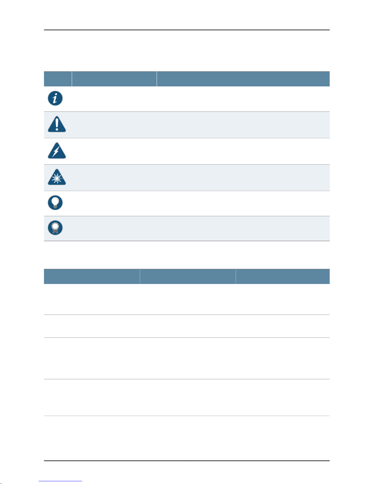
Table 1 on page xvi defines notice icons used in this guide.
xvCopyright © 2015, Juniper Networks, Inc.
Page 16
SRX110 Services Gateway Hardware Guide for H2 Model Numbers
Table 1: Notice Icons
DescriptionMeaningIcon
Indicates important features or instructions.Informational note
Indicates a situation that might result in loss of data or hardware damage.Caution
Alerts you to the risk of personal injury or death.Warning
Alerts you to the risk of personal injury from a laser.Laser warning
Indicates helpful information.Tip
Table 2 on page xvi defines the text and syntax conventions used in this guide.
Table 2: Text and Syntax Conventions
Represents text that you type.Bold text like this
Fixed-width text like this
Italic text like this
Italic text like this
Represents output that appears on the
terminal screen.
•
Introduces or emphasizes important
new terms.
•
Identifies guide names.
•
Identifies RFC and Internet draft titles.
Represents variables (options for which
you substitute a value) in commands or
configuration statements.
Alerts you to a recommended use or implementation.Best practice
ExamplesDescriptionConvention
To enter configuration mode, type the
configure command:
user@host> configure
user@host> show chassis alarms
No alarms currently active
•
A policy term is a named structure
that defines match conditions and
actions.
•
Junos OS CLI User Guide
•
RFC 1997, BGP Communities Attribute
Configure the machine’s domain name:
[edit]
root@# set system domain-name
domain-name
Copyright © 2015, Juniper Networks, Inc.xvi
Page 17
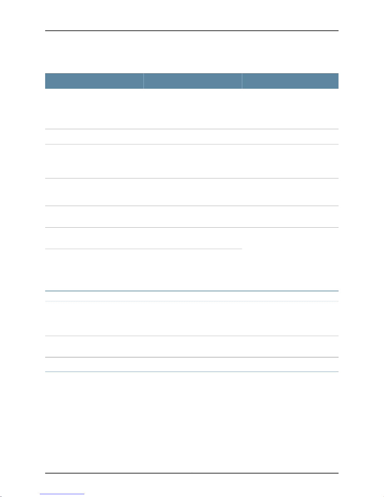
Table 2: Text and Syntax Conventions (continued)
Text like this
Represents names of configuration
statements, commands, files, and
directories;configurationhierarchylevels;
or labels on routing platform
components.
About the Documentation
ExamplesDescriptionConvention
•
To configure a stub area, include the
stub statement at the [edit protocols
ospf area area-id] hierarchy level.
•
The console port is labeled CONSOLE.
stub <default-metric metric>;Encloses optional keywords orvariables.< > (angle brackets)
| (pipe symbol)
# (pound sign)
[ ] (square brackets)
Indention and braces ( { } )
; (semicolon)
GUI Conventions
Bold text like this
Indicates a choice between the mutually
exclusivekeywords or variables on either
side of the symbol. The set of choices is
often enclosed in parenthesesfor clarity.
same lineas the configuration statement
to which it applies.
Encloses a variable for which you can
substitute one or more values.
Identifies a level in the configuration
hierarchy.
Identifies a leaf statement at a
configuration hierarchy level.
Representsgraphicaluser interface (GUI)
items you click or select.
broadcast | multicast
(string1 | string2 | string3)
rsvp { # Required for dynamic MPLS onlyIndicates a comment specified on the
community name members [
community-ids ]
[edit]
routing-options {
static {
route default {
nexthop address;
retain;
}
}
}
•
In the Logical Interfaces box, select
All Interfaces.
•
To cancel the configuration, click
Cancel.
> (bold right angle bracket)
Documentation Feedback
We encourage you to provide feedback, comments, and suggestions so that we can
improve the documentation. You can provide feedback by using either of the following
methods:
•
Online feedback rating system—On any page at the Juniper Networks Technical
Documentation site at http://www.juniper.net/techpubs/index.html, simply click the
stars to rate thecontent, and use the pop-up form toprovide uswith information about
your experience. Alternately, you can use the online feedback form at
https://www.juniper.net/cgi-bin/docbugreport/.
Separates levels in a hierarchy of menu
selections.
In the configuration editor hierarchy,
select Protocols>Ospf.
xviiCopyright © 2015, Juniper Networks, Inc.
Page 18

SRX110 Services Gateway Hardware Guide for H2 Model Numbers
•
E-mail—Sendyour comments to[email protected]. Include the document
or topic name, URL or page number, and software version (if applicable).
Requesting Technical Support
Technical product support is available through theJuniper Networks Technical Assistance
Center (JTAC). If you are a customer with an active J-Care or Partner Support Service
support contract, or are covered under warranty, and need post-sales technical support,
you can access our tools and resources online or open a case with JTAC.
•
JTAC policies—For a complete understanding of our JTAC procedures and policies,
review the JTAC User Guide located at
http://www.juniper.net/us/en/local/pdf/resource-guides/7100059-en.pdf.
•
Product warranties—For product warranty information, visit
http://www.juniper.net/support/warranty/.
•
JTAC hours of operation—The JTAC centers have resources available 24 hours a day,
7 days a week, 365 days a year.
Self-Help Online Tools and Resources
For quick and easy problem resolution, Juniper Networks has designed an online
self-service portal called the Customer Support Center (CSC) that provides you with the
following features:
•
Find CSC offerings: http://www.juniper.net/customers/support/
•
Search for known bugs: http://www2.juniper.net/kb/
•
Find product documentation: http://www.juniper.net/techpubs/
•
Find solutions and answer questions using our Knowledge Base: http://kb.juniper.net/
•
Download the latest versions of software and review release notes:
http://www.juniper.net/customers/csc/software/
•
Search technical bulletins for relevant hardware and software notifications:
http://kb.juniper.net/InfoCenter/
•
Join and participate in the Juniper Networks Community Forum:
http://www.juniper.net/company/communities/
•
Open a case online in the CSC Case Management tool: http://www.juniper.net/cm/
To verify service entitlement by product serialnumber,use ourSerial Number Entitlement
(SNE) Tool: https://tools.juniper.net/SerialNumberEntitlementSearch/
Opening a Case with JTAC
You can open a case with JTAC on the Web or by telephone.
•
Use the Case Management tool in the CSC at http://www.juniper.net/cm/.
•
Call 1-888-314-JTAC (1-888-314-5822 toll-free in the USA, Canada, and Mexico).
Copyright © 2015, Juniper Networks, Inc.xviii
Page 19

About the Documentation
For international or direct-dial options in countries without toll-free numbers, see
http://www.juniper.net/support/requesting-support.html.
xixCopyright © 2015, Juniper Networks, Inc.
Page 20

SRX110 Services Gateway Hardware Guide for H2 Model Numbers
Copyright © 2015, Juniper Networks, Inc.xx
Page 21

PART 1
Overview
•
System Overview on page 3
•
Hardware Component Overview on page 9
•
Chassis Description on page 15
1Copyright © 2015, Juniper Networks, Inc.
Page 22

SRX110 Services Gateway Hardware Guide for H2 Model Numbers
Copyright © 2015, Juniper Networks, Inc.2
Page 23

CHAPTER 1
System Overview
•
SRX110 Services Gateway Description on page 3
•
SRX110 Services Gateway Hardware Features on page 4
•
SRX110 Services Gateway Integrated VDSL2 Interface Overview on page 6
•
SRX110 Services Gateway Integrated VDSL2 Interface Key Features on page 6
•
SRX110 Services Gateway Integrated VDSL2 Interface Supported Profiles on page 7
SRX110 Services Gateway Description
This topic includes the following sections:
•
About the SRX110 Services Gateway on page 3
•
SRX110 Services Gateway Models on page 4
•
Accessing the SRX110 Services Gateway on page 4
About the SRX110 Services Gateway
The Juniper Networks SRX110 Services Gateway offers complete functionality and
flexibility for delivering secure and reliable data along with multiple integrated interfaces
that support WAN and LAN connectivity. The SRX110 Services Gateway supports
interfaces such as 3G USB modem and integrated very-high-bit-rate digital subscriber
line version 2 (VDSL2).
The VDSL2 feature enables faster data transmission.VDSL linesconnect service provider
networksand customer sites to providehigh-bandwidth applications such ashigh-speed
Internet access, telephone services such as voice over IP (VoIP), high-definition TV
(HDTV), and interactive gaming services over a single connection. On the SRX Series
Services Gateway, the integratedVDSL2 interface provides ADSLbackwardcompatibility.
The 3G USB modem enables wireless connectivity. The 3G-WAN USB port located at
the back panel of the device supports the external 3G USB modem using a Universal
Serial Bus (USB) modem extension cable.
The services gateway also provides security features such as IP Security (IPsec), virtual
privatenetwork (VPN),and firewall services forsmall and medium-sized companiesand
enterprise branch and remote offices. Additional security features also include Unified
ThreatManagement (UTM), which consists of IPS antispam, antivirus, and Web filtering.
3Copyright © 2015, Juniper Networks, Inc.
Page 24
SRX110 Services Gateway Hardware Guide for H2 Model Numbers
The SRX110 Services Gateway can be connected directly to traditional private networks
such as Multi Protocol Label Switching (MPLS) or to the public Internet.
The SRX110 Services Gateway runs the Junos operating system (Junos OS).
SRX110 Services Gateway Models
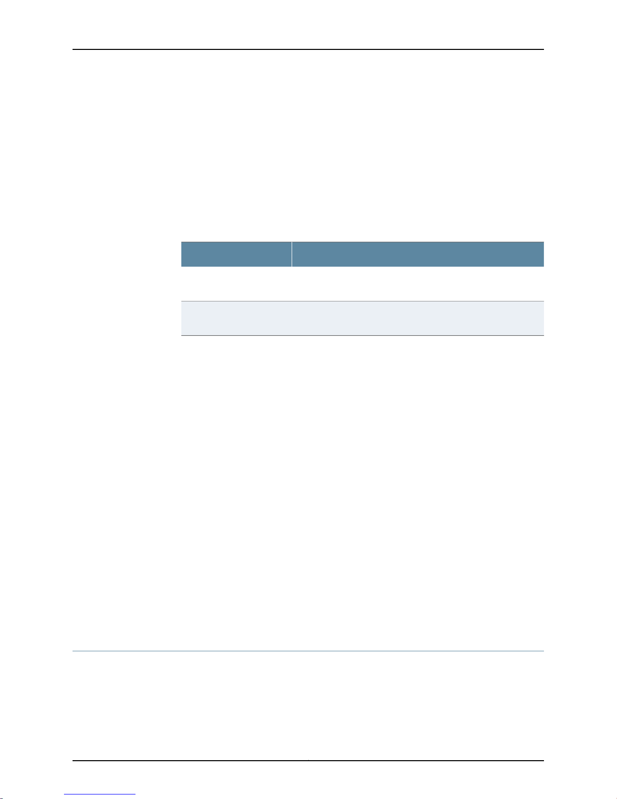
Table 3 on page 4 lists the SRX110 Services Gateway models with 2 GB memory. For
information on the models with 1 GB memory, see SRX110 Services Gateway Hardware
Guide for H Model Numbers.
Table 3: SRX110 Services Gateway Models
DescriptionModel
SRX110H2-VA
SRX110H2-VB
Accessing the SRX110 Services Gateway
Two user interfaces are available for monitoring, configuring, troubleshooting, and
managing the SRX110 Services Gateway:
•
J-Web interface: Web-based graphical interface that allows you to operate a services
gateway without commands. The J-Web interface provides access to all Junos OS
functionality and features.
•
Junos OS command-line interface (CLI): Command shell that runs on top of a
UNIX-based operating system kernel. The CLI is a straightforward command interface.
On a single line, you type commands that are executed when you press the Enter key.
The CLI provides command Help and command completion.
For more details on the SRX110 Services Gateway software features and licenses, see
the following topics:
•
Initial Configuration for Security Devices
•
Monitoring and Troubleshooting for Security Devices
SRX110 Services Gateway with 8 Fast Ethernet ports, 2 GB DRAM,
2 GB CompactFlash memory, and 1 VDSL/ADSL-POTS port
SRX110 Services Gateway with 8 Fast Ethernet ports, 2 GB DRAM,
2 GB CompactFlash memory, and 1 VDSL/ADSL-ISDN port
Related
Documentation
SRX110 Services Gateway Hardware Features on page 4•
• SRX110 Services Gateway Specifications on page 30
SRX110 Services Gateway Hardware Features
Table 4 onpage 5lists the hardware features supported on the SRX110 Services Gateway
models with 2 GB memory. For information on the models with 1 GB memory, see SRX110
Services Gateway Hardware Guide for H Model Numbers.
Copyright © 2015, Juniper Networks, Inc.4
Page 25
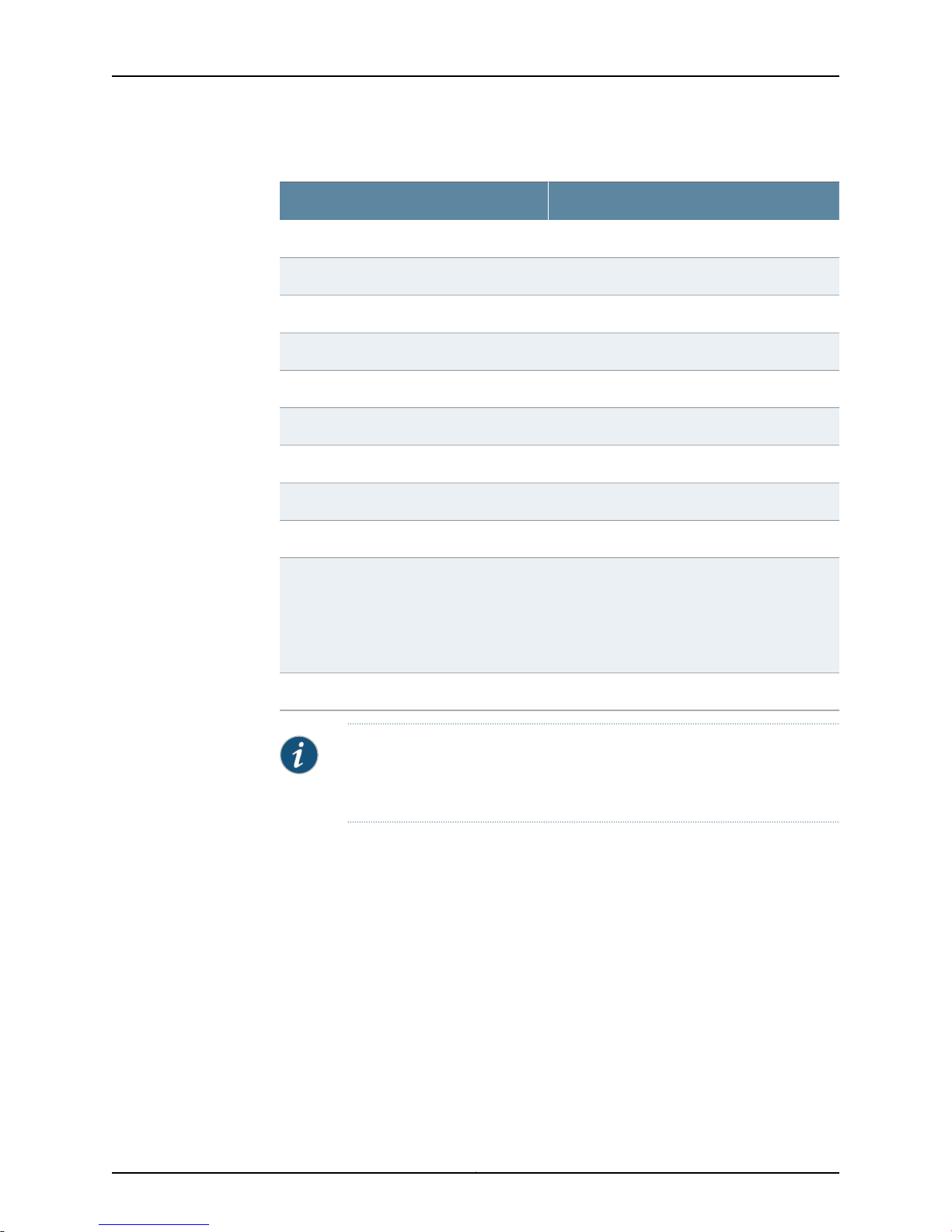
Table 4: SRX110 Services Gateway Hardware Features
DescriptionFeature
2 GBDDR Memory
60 W (12 VDC and 5 A)Power supply adapter
100 to 240 VACAC input voltage
50 to 60 HzAC input line frequency
1.5 A maximumAC adapter current rating
8Fast Ethernet ports
1Console port
1USB port
Chapter 1: System Overview
Related
Documentation
2 GBCompactFlash card
LEDs
Status, Alarm, Power, and 3G
•
For SRX110H2-VA—VDSL/ADSL-POTS (TX/RX
and SYNC)
•
For SRX110H2-VB—VDSL/ADSL-ISDN (TX/RX
and SYNC)
13G-WAN USB port (rear side)
NOTE: If there is any problem with the CompactFlash card, you must return
the services gateway for repair or replacement. For this, you need to contact
Juniper Networks Technical Assistance Center (JTAC).
For more details on Junos OS features and licenses for the SRX110 Services Gateway,
see the following topics:
•
Initial Configuration for Security Devices
•
Monitoring and Troubleshooting for Security Devices
SRX110 Services Gateway Description on page 3•
• SRX110 Services Gateway Specifications on page 30
5Copyright © 2015, Juniper Networks, Inc.
Page 26

SRX110 Services Gateway Hardware Guide for H2 Model Numbers
SRX110 Services Gateway Integrated VDSL2 Interface Overview
Very-high-bit-rate digital subscriber line (VDSL) technology is part of the xDSL family of
modem technologies. It provides fast data transmission over a single flat untwisted or
twisted pair of copper wires.
VDSL lines connect service provider networks and customer sites to provide
high-bandwidth applications (Triple Play services) such as high-speed Internet access,
telephoneservices suchas voice over IP(VoIP), high-definition TV (HDTV), andinteractive
gaming services over a singleconnection.VDSL2 is an enhancement to VDSL andpermits
the transmission of asymmetric (half-duplex).
VDSL2 uses:
•
RJ-11 connector to connect to the VDSL/ADSL-POTS port.
•
RJ-45 connector to connect to the VDSL/ADSL-ISDN port.
The services gateway supports integrated VDSL2. The integrated VDSL2 carries the
Ethernet backplane. On the SRX Series Services Gateway, integrated VDSL2 provides
ADSL backward compatibility.
Integrated VDSL2 is compatible with the ITU-T G.993.2 (VDSL2) standard.
For more information, see the Interfaces for Security Devices.
Related
Documentation
SRX110 Services Gateway Integrated VDSL2 Interface Key Features on page 6•
• SRX110 Services Gateway Integrated VDSL2 Interface Supported Profiles on page 7
• SRX110 Services Gateway Integrated VDSL2 Interface LEDs on page 22
• Configuring theIntegrated VDSL2Interface onthe SRX110Services Gatewayon page 103
SRX110 Services Gateway Integrated VDSL2 Interface Key Features
The following features are supported on integrated VDSL2:
•
ADSL/ADSL2/ADSL2+ backward compatibility with POTS supporting Annex-A
(Annex-M) and ISDN supporting Annex-B
•
Packet Mode Transfer (PTM) or Ethernet in the First Mile (EFM) (802.3ah)
•
Operation,Administration,and Maintenance (OAM) support forADSL/ADSL2/ADSL2+
mode
•
Asynchronous Transfer Mode (ATM) quality of service (QoS) (supported only when
the VDSL2 interface is operating in ADSL2 mode)
•
Multilink Point-to-Point Protocol (MLPPP) (supported only when the VDSL2 interface
is operating in ADSL2 mode)
Copyright © 2015, Juniper Networks, Inc.6
Page 27
Chapter 1: System Overview
•
Support for a maximum of 10 permanent virtual connections (PVCs) (only in
ADSL/ADSL2/ADSL2+ mode)
•
Dying Gasp support (ADSL/ADSL2/ADSL2+ and VDSL2 modes)
Related
Documentation
SRX110 Services Gateway Integrated VDSL2 Interface Overview on page 6•
• SRX110 Services Gateway Integrated VDSL2 Interface LEDs on page 22
• Configuring theIntegrated VDSL2Interface onthe SRX110Services Gatewayon page 103
SRX110 Services Gateway Integrated VDSL2 Interface Supported Profiles
A profile is a table that contains a list of preconfigured VDSL2 settings. Table 5 on page 7
lists the different profiles supported on integrated VDSL2, along with their data rates.
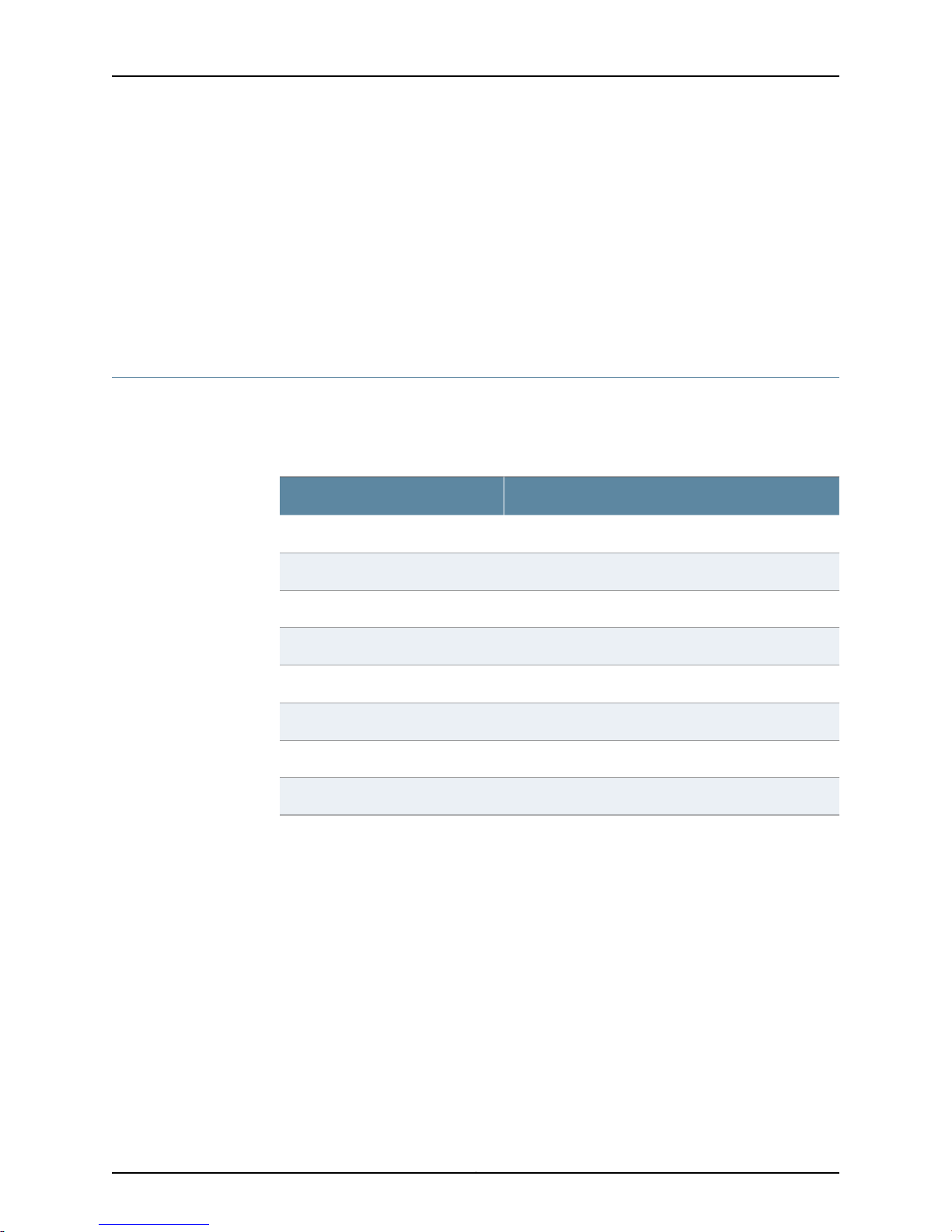
Table 5: Profiles Supported on the Integrated VDSL2 Interface
Data Rate (Mbps)Profile
508a
508b
508c
508d
6812a
Related
Documentation
6812b
10017a
Auto-negotiated (based on profile)Auto
• SRX110 Services Gateway Integrated VDSL2 Interface Overview on page 6
• SRX110 Services Gateway Integrated VDSL2 Interface LEDs on page 22
• Configuring theIntegrated VDSL2Interface onthe SRX110Services Gatewayon page 103
7Copyright © 2015, Juniper Networks, Inc.
Page 28

SRX110 Services Gateway Hardware Guide for H2 Model Numbers
Copyright © 2015, Juniper Networks, Inc.8
Page 29
CHAPTER 2
g033607
Hardware Component Overview
•
SRX110 Services Gateway Power Supply on page 9
•
SRX110 Services Gateway 3G USB Modem Overview on page 10
•
SRX110 Services Gateway 3G USB Modem Key Features on page 12
SRX110 Services Gateway Power Supply
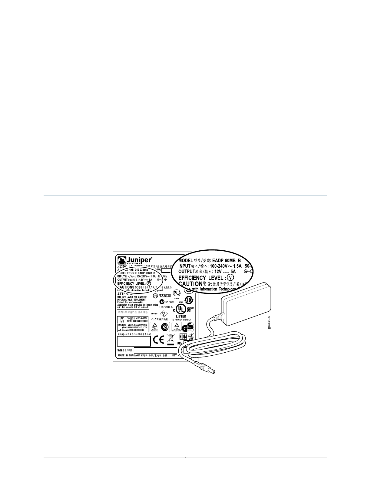
The power supply for the SRX110 Services Gateway is external. You must use the power
supply adapter provided by Juniper Networks to provide power to the services gateway.
Figure 1 on page 9 shows the label for the 12 V power supply.
Figure 1: SRX110 Services Gateway — 12 V Power Supply
Related
Documentation
Monitoring the SRX110 Services Gateway Power System on page 114•
• Powering On the SRX110 Services Gateway on page 80
• Powering Off the SRX110 Services Gateway on page 81
9Copyright © 2015, Juniper Networks, Inc.
Page 30

SRX110 Services Gateway Hardware Guide for H2 Model Numbers
SRX110 Services Gateway 3G USB Modem Overview
This topic includes the following sections:
•
Introduction to the SRX110 Services Gateway 3G USB Modem on page 10
•
SRX110 Services Gateway 3G USB Modem—Supported Modem Types on page 10
•
Using the SRX110 Services Gateway 3G USB Modem on page 10
Introduction to the SRX110 Services Gateway 3G USB Modem
WirelessWANaccess is becomingwidely available and comparably priced withIntegrated
Services Digital Network (ISDN) and Digital Subscriber Line (DSL). The SRX110 Services
Gateway supports a wireless interface as a backup for primary interfaces such as Fast
Ethernet.
To facilitate wireless connectivity, the device has a 3G-WAN USB port on the back panel
that supports the external 3G USB modem using a USB modem extension cable. For
more information on the back panel of the device, see SRX110 Services Gateway Front
Panel and Back Panel Views with 3G and Integrated VDSL2.
SRX110 Services Gateway 3G USB Modem—Supported Modem Types
Table 6 on page 10lists the wireless modemssupported on theSRX110 Services Gateway.
Table 6: Wireless USB Modems Supported by the SRX110 Services
Gateway
Release SupportedWireless USB Modem
Junos OS Release 11.2 R3 and later.Sierra Wireless Compass 888. Not available from
Juniper Networks.
Junos OS Release 11.2 R3 and later.Sierra Wireless AirCard 319U. Not available from
Juniper Networks.
Using the SRX110 Services Gateway 3G USB Modem
To use the 3G USB modem, you plug one end of the USB modem extension cable into
the 3G-WAN USB port on the rear side of the device, and then plug the 3G USB modem
into the USB modem extension cable-mount slot. This enables you to dial a wireless call
to the 3G wireless service provider network, which acts as an Internet gateway. To use
the 3G USB modem as a backup interface, you can use the dialer feature available in the
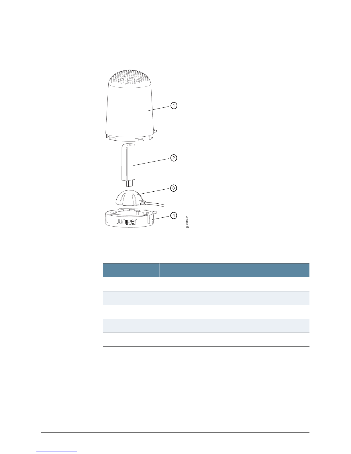
services gateway. The 3G USB modem is secured with a USB protection cover as shown
in Figure 2 on page 11.
Copyright © 2015, Juniper Networks, Inc.10
Page 31
g033622
Chapter 2: Hardware Component Overview
Figure 2: 3G USB Modem with USB Protection Cover
Related
Documentation
Table 7 on page 11 lists the components of the 3G USB modem with USB protection
cover.
Table 7: 3G USB Modem with USB Protection Cover Components
ComponentNumber
USB mount top cover1
USB modem2
USB mount (magnetic/non-magnetic)3
USB mount base4
Lock5
Installing a 3G USB Modem in the SRX110 Services Gateway USB Port on page 67•
• SRX110 Services Gateway 3G-WAN USB Port Physical Specifications on page 32
• Configuring the 3G USB Modem on the SRX110 Services Gateway on page 102
11Copyright © 2015, Juniper Networks, Inc.
Page 32
SRX110 Services Gateway Hardware Guide for H2 Model Numbers
SRX110 Services Gateway 3G USB Modem Key Features
The 3G USB modem provides the following key features:
•
Onboard Subscriber Identity Module (SIM)—All GSM cards have an onboard SIM. The
service provider populates this SIM with the subscriber service parameters.
•
Unlocking support—You can unlock GSM USB modems from the Junos OS CLI. If the
SIM is locked, you need to unlock it before making a call.
NOTE: Only GSM cards support locking and unlocking of the SIM.
•
Interface support—The 3G USB modem interface supports the IP-over-PPP interface
from the network through the wireless link.
•
Dial-out support—The dialer interface can place calls and has multiple features such
as dial-backup, dialer-watchlist, and dialer-filter. The dialer interface can use the 3G
USB modem to support the dial-out feature.
NOTE: The 3G USB modem does not support the dial-in feature.
•
Card information availability—You can use CLI commands to obtain information about
a 3G USB modem, such as type, version, wireless status, and user profiles.
Copyright © 2015, Juniper Networks, Inc.12
Page 33
Chapter 2: Hardware Component Overview
•
Security:
•
PIN lock support—GSM cards support PIN lock, which prevents unauthorized access
and use of the wireless account.
•
SIM card lock/unlock—You can use CLI request commands to lock or unlock the SIM
card.
•
PIN code storage option—You can store the PIN code you provide in the services
gateway configuration so that the SIM can be unlocked without the need for user
intervention every time the device is rebooted or reset.
NOTE: Currently, all GSM cards support PIN-protected SIMs.
Related
Documentation
• SRX110 Services Gateway 3G USB Modem Overview on page 10
• Installing a 3G USB Modem in the SRX110 Services Gateway USB Port on page 67
• SRX110 Services Gateway 3G-WAN USB Port Physical Specifications on page 32
13Copyright © 2015, Juniper Networks, Inc.
Page 34

SRX110 Services Gateway Hardware Guide for H2 Model Numbers
Copyright © 2015, Juniper Networks, Inc.14
Page 35
CHAPTER 3
g033602
1 3
4
2
5 6 87
Chassis Description
•
SRX110 Services Gateway Front Panel and Back Panel Views with 3G and Integrated
VDSL2 on page 15
•
SRX110 Services Gateway Built-In Interfaces on page 17
•
SRX110 Services Gateway LEDs on page 19
•
SRX110 Services Gateway Integrated VDSL2 Interface LEDs on page 22
•
SRX110 Services Gateway Boot Devicesand Dual-Root Partitioning Scheme onpage22
SRX110 Services Gateway Front Panel and Back Panel Views with 3G and Integrated
VDSL2
This topic includes the following sections:
•
SRX110 Services Gateway Front Panel View with 3G and Integrated VDSL2 on page 15
•
SRX110 Services Gateway Back Panel View on page 16
SRX110 Services Gateway Front Panel View with 3G and Integrated VDSL2
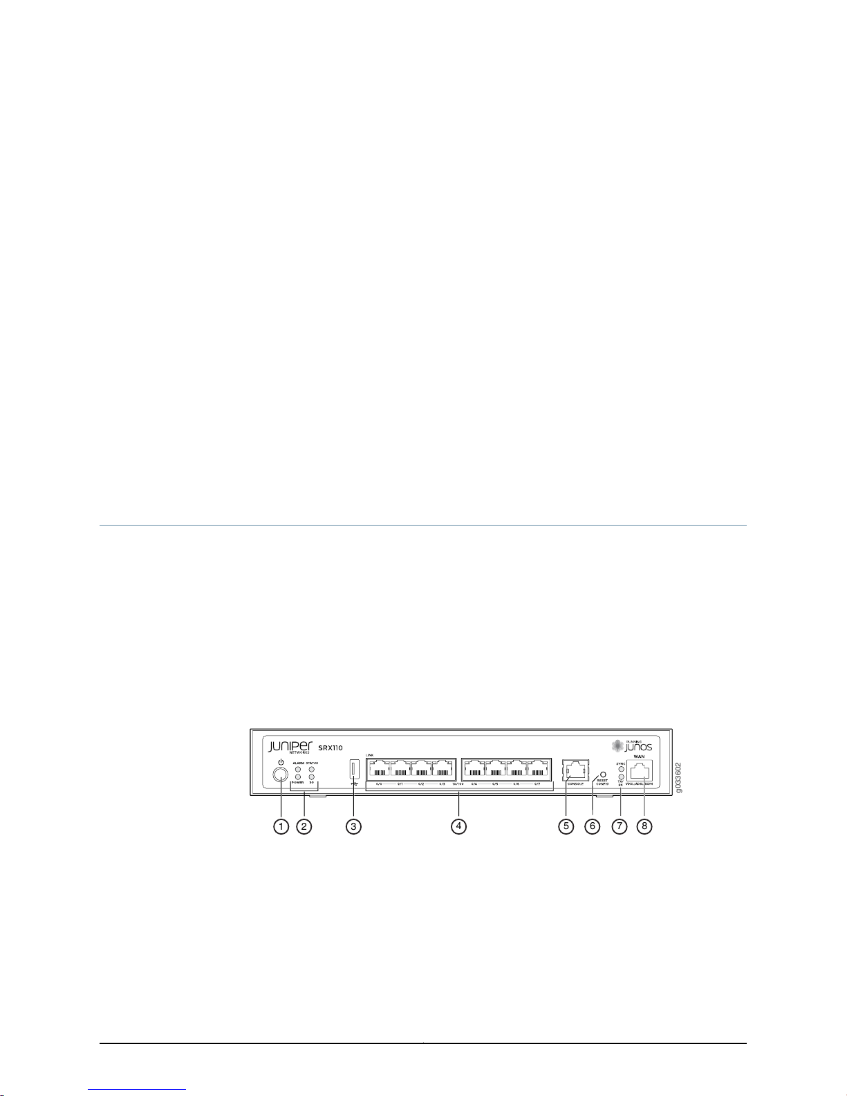
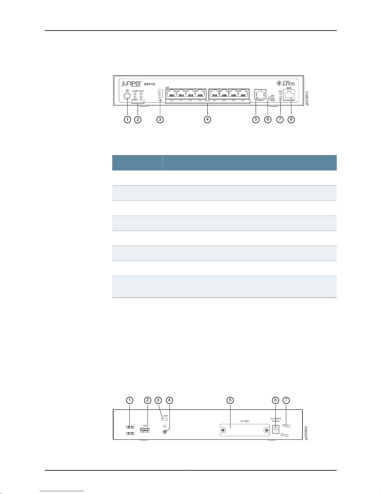
Figure 3 on page 15 and Figure 4 on page 16 show the front panels of the SRX110 Services
Gateway models SRX110H2-VA and SRX110H2-VB.
Figure 3: SRX110 Services Gateway Front Panel (SRX110H2-VA)
15Copyright © 2015, Juniper Networks, Inc.
Page 36
g033604
1 3
4
2
5 6 87
g033603
1 3 4
2 5
6 7
SRX110 Services Gateway Hardware Guide for H2 Model Numbers
Figure 4: SRX110 Services Gateway Front Panel (SRX110H2-VB)
Table 8 on page 16 lists the front panel components of the SRX110 Services Gateway.
Table 8: SRX110 Services Gateway Front Panel Components
ComponentNumber
Power button1
LEDs: Alarm, Status, Power, and 3G2
USB port3
Fast Ethernet ports4
Console port5
Reset Config button6
LEDs: SYNC and TX/RX7
•
8
For SRX110H2-VA—VDSL/ADSL-POTS
•
For SRX110H2-VB—VDSL/ADSL-ISDN
For more information on the front panel components, see the following topics:
•
SRX110 Services Gateway Built-In Interfaces on page 17
•
SRX110 Services Gateway LEDs on page 19
•
SRX110 Services Gateway Boot Devicesand Dual-Root Partitioning Scheme onpage22
SRX110 Services Gateway Back Panel View
Figure 5 on page 16 shows the back panel of the SRX110 Services Gateway.
Figure 5: SRX110 Services Gateway Back Panel
Copyright © 2015, Juniper Networks, Inc.16
Page 37
Chapter 3: Chassis Description
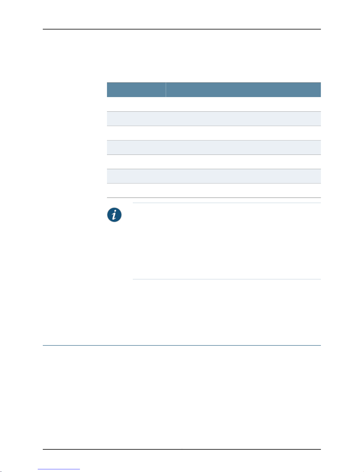
Table 9 on page 17 lists the back panel components of the SRX110 Services Gateway.
Table 9: SRX110 Services Gateway Back Panel Components
ComponentNumber
Cable tie holder1
3G-WAN USB port2
Lock3
Grounding point4
CompactFlash card5
Power supply unit6
Cable tie holder7
NOTE:
•
If there is any problem with the CompactFlash card, you must return the
services gateway for repair or replacement. For this, you need to contact
Juniper Networks Technical Assistance Center (JTAC).
•
The cable tie holder provides support for holding the power cord to the
power supply point.
•
The lock allows you to lock and secure the device to the installation site.
Related
Documentation
SRX110 Services Gateway Specifications on page 30•
• SRX110 Services Gateway Built-In Interfaces on page 17
• SRX110 Services Gateway LEDs on page 19
• SRX110 Services Gateway Power Supply on page 9
SRX110 Services Gateway Built-In Interfaces
Table 10 on page 18 summarizes the interface ports supported on the SRX110 Services
Gateway.
17Copyright © 2015, Juniper Networks, Inc.
Page 38

SRX110 Services Gateway Hardware Guide for H2 Model Numbers
Table 10: SRX110 Services Gateway Built-In Hardware Interfaces
DescriptionSpecificationInterface
Fast Ethernet
Universal Serial Bus (USB)
The Fast Ethernet ports:
•
Consist of eight fixed ports
•
Are labeled as port 0/0 to
port 0/7 on the front panel
•
Provide link speeds of
10/100 Mbps
•
Operate in full-duplex and
half-duplex modes
•
Support flow control
•
Support autonegotiation
•
Support autosensing
The USB port:
•
Consists of one port
•
Supports the following
modes:
•
Full-speed
•
High-speed
•
Complies withUSB revision
2.0
The Fast Ethernet ports can be
used:
•
To provide LAN connectivity
to hubs, switches, local
servers, and workstations.
•
To forward incoming data
packets to the device.
•
To receive outgoing data
packets from the device.
The USB port can be used:
•
To support a USB storage
device that functions as a
secondary boot device in
case of internal flash
memory device failure on
startup (if the USB storage
device is installed and
configured).
NOTE: You must install and
configure the USB storage
device on the USB port to
use it as a secondary boot
device. Additionally, theUSB
device must have Junos OS
installed.
Console
The console port:
•
Consists of one port
•
Uses an RJ-45 serial cable
connector
•
Supports the RS-232
(EIA-232) standard
•
To provide the USB
interfaces that are used to
communicate with many
types of USB storage
devicessupported by Juniper
Networks.
The console port can be used:
•
To provide the console
interface.
•
To function as a
management port for
logging in to a device
directly.
•
To configure the device
using the CLI.
Copyright © 2015, Juniper Networks, Inc.18
Page 39
g033605
Chapter 3: Chassis Description
Table 10: SRX110 Services Gateway Built-In Hardware
Interfaces (continued)
DescriptionSpecificationInterface
Integrated VDSL2 interface
3G USB modem
Related
Documentation
SRX110 Services Gateway Specifications on page 30•
• SRX110 Services Gateway Front Panel and Back Panel Views with 3G and Integrated
VDSL2 on page 15
• SRX110 Services Gateway LEDs on page 19
SRX110 Services Gateway LEDs
This topic includes the following sections:
•
SRX110 Services Gateway Front Panel LEDs on page 19
•
SRX110 Services Gateway Ethernet Port LEDs on page 21
The VDSL2 port:
•
Consists of one port
•
Uses an RJ-11 connector for
VDSL/ADSL-POTS
•
Uses anRJ-45 connectorfor
VDSL/ADSL-ISDN
The 3G-WAN USB port on the
rear side uses a USB modem
extensioncable to supportthe
external 3G USB modem.
The VDSL2 portcan beused to
provide LAN and WAN
functionality, along with
connectivity to various media
types.
The 3G USB modem provides
wireless connectivity.
SRX110 Services Gateway Front Panel LEDs
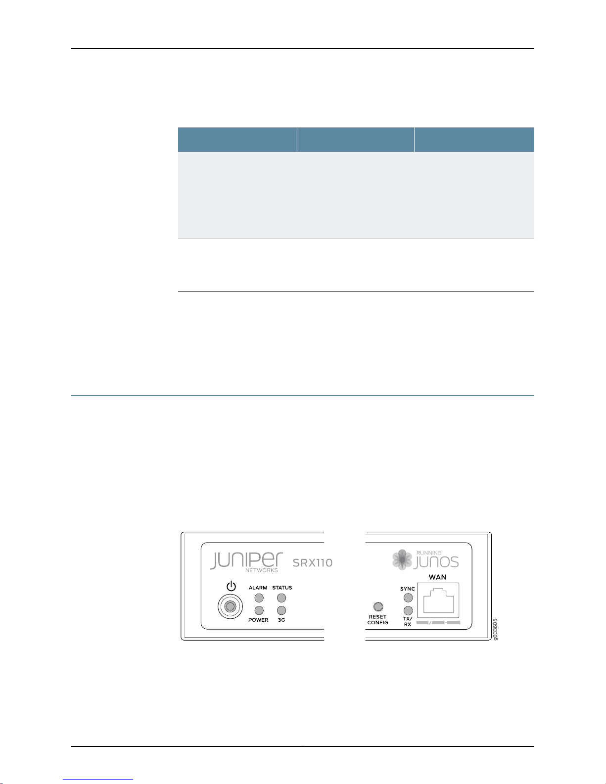
Figure 6 on page 19 shows the SRX110 Services Gateway Front Panel LEDs.
Figure 6: SRX110 Services Gateway Front Panel LEDs
Table 11 on page 20 lists the LED indicators on the SRX110 Services Gateway front panel.
19Copyright © 2015, Juniper Networks, Inc.
Page 40

SRX110 Services Gateway Hardware Guide for H2 Model Numbers
Table 11: SRX110 Services Gateway Front Panel Components LEDs
UsageDescriptionComponent
Alarm LED
Status LED
Power LED
The Alarm LED has the following indicator colors:
•
Solid red indicates a critical alarm.
•
Solid amber indicates a major alarm.
•
Green indicates that the device is functioning
normally with no alarms.
•
Off indicates thatthe device is notpoweredon.
NOTE: When the system is up and running, if
the Alarm LED is off, it indicates that no alarms
are present on the device.
The Status LEDhas thefollowingindicatorcolors:
•
Solid green indicates that the device is
functioning normally.
•
Solid amberindicatesthat the deviceis starting
up.
•
Solid red indicates that the device has failed.
•
Off indicates thatthe device is notpoweredon.
The Power LED has the following indicator colors:
•
Solid green indicates that the device is
functioning normally.
•
Solid amber indicates that the Power button
has been pressed and quickly released. The
device is gracefully shutting down.
•
Solid red indicates that there is a problem with
the power supply.
•
Off indicates that the device is not receiving
power.
The Alarm LED can be used
to gather information on
critical, major, or minor
alarms or to determineif the
device is functioning
normally.
The Status LED can be used
to determine whether the
device is starting up, is
functioning normally, or has
failed.
The Power LED can be used
to determine if the device is
receiving power.
3G LED
The 3G LED has the following indicator colors:
•
Solid green indicates that the 3G USB modem
is functioningnormallyor connected to network.
•
Solid red indicates that the 3G USB modem is
not registered with network.
•
Solid amberindicates that the 3G USB modem
is registered with network.
•
Off indicates that the 3G USB modem is not
detected.
The 3G LED can be used to
determine if the 3G USB
modem is plugged in.
NOTE: The 3G LED will be
functional only if you reboot
the services gateway after
plugging in the modem.
Copyright © 2015, Juniper Networks, Inc.20
Page 41
Chapter 3: Chassis Description
Table 11: SRX110 Services Gateway Front Panel Components
LEDs (continued)
UsageDescriptionComponent
SYNC LED
TX/RX LED
The SYNC LED for the VDSL2 interface has the
following indicator colors:
•
Solid green indicates that the VDSL2 link is up.
•
Blinking green indicates that the VDSL2 link is
in training and there is no connection to CO.
NOTE: Training refers to the negotiation of the
best mode for a DSL connection.
•
Off indicates that interface has not yet booted
up.
The TX/RX LED for the VDSL2 interface has the
following indicator colors:
•
Blinking green indicates that there is traffic.
•
Solid green indicates an invalid state.
•
Off indicates that there is no traffic.
SRX110 Services Gateway Ethernet Port LEDs
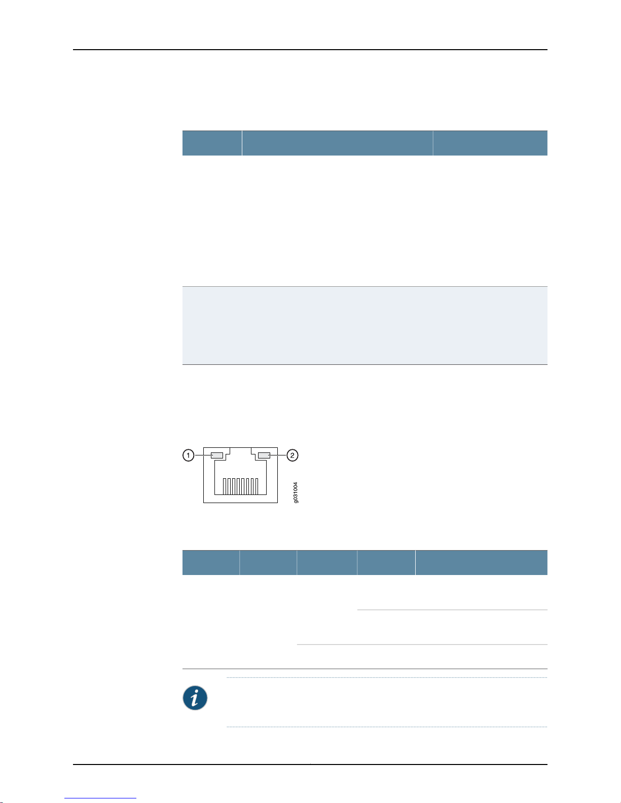
On the device, each Fast Ethernet port has two LEDs. Figure 7 on page 21 shows the
device Ethernet port LEDs.
Figure 7: SRX110 Services Gateway Ethernet Port LEDs
The SYNC LED can be used
to determine if the VDSL2
link is connected.
The TX/RX LED can be used
to determine if there is any
traffic through the VDSL
interface.
Table 12 on page 21 describes the built-in Ethernet port LEDs.
Table 12: SRX110 Services Gateway Built-In Ethernet Port LEDs
1
DescriptionStateColorFunctionNumber
On, blinkingGreenLINK/ACTIVE
LED
On, not
blinking
Link is active. Data
communication is taking place.
Link is active. No data
communication is taking place.
Link is inactive.Off
NOTE: The LED marked as 2 in Figure 7 on page 21 is not functional in this
release.
21Copyright © 2015, Juniper Networks, Inc.
Page 42
SRX110 Services Gateway Hardware Guide for H2 Model Numbers
Related
Documentation
SRX110 Services Gateway Specifications on page 30•
• SRX110 Services Gateway Front Panel and Back Panel Views with 3G and Integrated
VDSL2 on page 15
• SRX110 Services GatewayBoot Devices and Dual-Root Partitioning Schemeon page22
SRX110 Services Gateway Integrated VDSL2 Interface LEDs
The integrated VDSL2 interface has two LEDs. Table 13 on page 22 describes the LED
states.
Table 13: Integrated VDSL2 LEDs
DescriptionStateColorLED
Indicates that the VDSL2 interface link is up.OnGreenSYNC
Blinking
Off
Indicates training is in progress and there is
no connection to CO.
NOTE: Training refers to the negotiation of
the best mode for a DSL connection.
Indicates that interface has not yet booted
up.
Indicates that traffic is passing through.BlinkingGreenTX/RX
Indicates that it is an invalid state.On
Indicates that no traffic is passing through.Off
Related
Documentation
SRX110 Services Gateway Integrated VDSL2 Interface Overview on page 6•
• Configuring theIntegrated VDSL2Interface onthe SRX110Services Gatewayon page 103
SRX110 Services Gateway Boot Devices and Dual-Root Partitioning Scheme
This topic includes the following sections:
•
Boot Devices on page 22
•
Dual-Root Partitioning Scheme on page 23
Boot Devices
The SRX110 Services Gateway can boot from two devices:
•
CompactFlash (default; always present)
•
USB storage key (alternate)
Copyright © 2015, Juniper Networks, Inc.22
Page 43

Dual-Root Partitioning Scheme
Dual-root partitions allow services gateways to remain functional if the file system
becomes corrupted, and they facilitate easy recovery of the corrupted file system.
The dual-root partitioning scheme keeps the primary and backup Junos OS images in
two independently bootable root partitions. If the primary root partition becomes
corrupted,the system can boot from the backup Junos OS imagein theother rootpartition
and remain fully functional.
When the SRX110 Services Gateway powers up, it tries to boot Junos OS from the default
storage medium. If the device fails to boot from the default storage medium, it tries to
boot from the alternate storage medium. With the dual-root partitioning scheme, the
services gateway first tries to boot Junos OS from the primary root partition and then
from thebackup root partition on the defaultstoragemedium. Ifboth primary and backup
root partitions of a storage medium fail to boot, then the device tries to boot from the
next available type of storage media. The services gateway remains fully functional even
if it boots Junos OS from the backup root partition of the storage medium.
Chapter 3: Chassis Description
Related
Documentation
• SRX110 Services Gateway Front Panel and Back Panel Views with 3G and Integrated
VDSL2 on page 15
• SRX110 Services Gateway LEDs on page 19
• SRX110 Services Gateway Power Supply on page 9
• SRX110 Services Gateway Specifications on page 30
23Copyright © 2015, Juniper Networks, Inc.
Page 44

SRX110 Services Gateway Hardware Guide for H2 Model Numbers
Copyright © 2015, Juniper Networks, Inc.24
Page 45

PART 2
Site Planning and Specifications
•
Planning and Preparing the Site on page 27
•
Power Requirements and Specifications on page 37
•
Cable Specifications and Pinouts on page 41
25Copyright © 2015, Juniper Networks, Inc.
Page 46

SRX110 Services Gateway Hardware Guide for H2 Model Numbers
Copyright © 2015, Juniper Networks, Inc.26
Page 47

CHAPTER 4
Planning and Preparing the Site
•
Site Preparation Checklist for the SRX110 Services Gateway on page 27
•
General Site Guidelines for Installing the SRX110 Services Gateway on page 30
•
SRX110 Services Gateway Specifications on page 30
•
SRX110 Services Gateway 3G-WAN USB Port Physical Specifications on page 32
•
SRX110 Services Gateway Cabinet Requirements on page 32
•
SRX110 Services Gateway Rack Requirements on page 33
•
Clearance Requirements for Airflow andHardware Maintenance ofthe SRX110Services
Gateway on page 34
Site Preparation Checklist for the SRX110 Services Gateway
The checklist in Table 14 on page 27 summarizes the tasks you need to perform when
preparing a site for installing the services gateway.
Table 14: Site Preparation Checklist for Services Gateway Installation
Environment
Verify that the
environmental factors
such as temperature
and humidity do not
exceed device
tolerances.
Power
Additional
InformationItem or Task
“SRX110
Services
Gateway
Specifications”
on page 30
NotesDatePerformed By
27Copyright © 2015, Juniper Networks, Inc.
Page 48

SRX110 Services Gateway Hardware Guide for H2 Model Numbers
Table 14: Site Preparation Checklist for Services Gateway
Installation (continued)
Additional
InformationItem or Task
NotesDatePerformed By
•
Measure the distance
between the external
power sources and
the device installation
site.
•
Locate sites for
connection of system
grounding.
•
Calculate the power
consumption and
requirements.
Rack Requirements
Verify that your rack
meets the minimum
requirements.
Rack Installation
•
Plan therack location,
including therequired
space clearances.
•
Secure the rackto the
floor and the building
structure.
“SRX110
Services
Gateway Site
ElectricalWiring
Guidelines” on
page 37
“SRX110
Services
Gateway Power
Specifications
and
Requirements”
on page 39
“SRX110
Services
Gateway Rack
Requirements”
on page 33
“Preparing the
SRX110 Services
Gateway for
Rack-Mount
Installation” on
page 55
Cabinet Requirements
•
Verify that your
cabinet meets the
minimum
requirements.
•
Plan the cabinet
location,including the
required space
clearances.
Wall Installation
“SRX110
Services
Gateway
Cabinet
Requirements”
on page 32
Copyright © 2015, Juniper Networks, Inc.28
Page 49

Chapter 4: Planning and Preparing the Site
Table 14: Site Preparation Checklist for Services Gateway
Installation (continued)
Additional
InformationItem or Task
NotesDatePerformed By
•
Verify that the area
selected meets the
minimum
requirements.
•
Verify that you have
the required hardware
for proceeding with
the installation.
Desktop Installation
•
Verify that the area
selected meets the
minimum
requirements.
•
Plan the installation
location, including
required space
clearances and
airflow requirements.
Cables
•
Acquire cables and
connectors.
•
Reviewthe maximum
distance allowed for
each cable. Choose
the length of cable
based on thedistance
between the
hardware
components being
connected.
•
Plan thecable routing
and management.
“Preparing the
SRX110 Services
Gateway for
Wall-Mount
Installation” on
page 57
“Preparing the
SRX110 Services
Gateway for
Desk-Mount
Installation” on
page 56
“InterfaceCable
and Wire
Specifications
for the SRX110
Services
Gateway” on
page 41
Related
Documentation
Installation Overview for the SRX110 Services Gateway on page 47•
• General Site Guidelines for Installing the SRX110 Services Gateway on page 30
• SRX110 Services Gateway Cabinet Requirements on page 32
• SRX110 Services Gateway Rack Requirements on page 33
• Clearance Requirements for Airflow andHardware Maintenance of the SRX110Services
Gateway on page 34
29Copyright © 2015, Juniper Networks, Inc.
Page 50
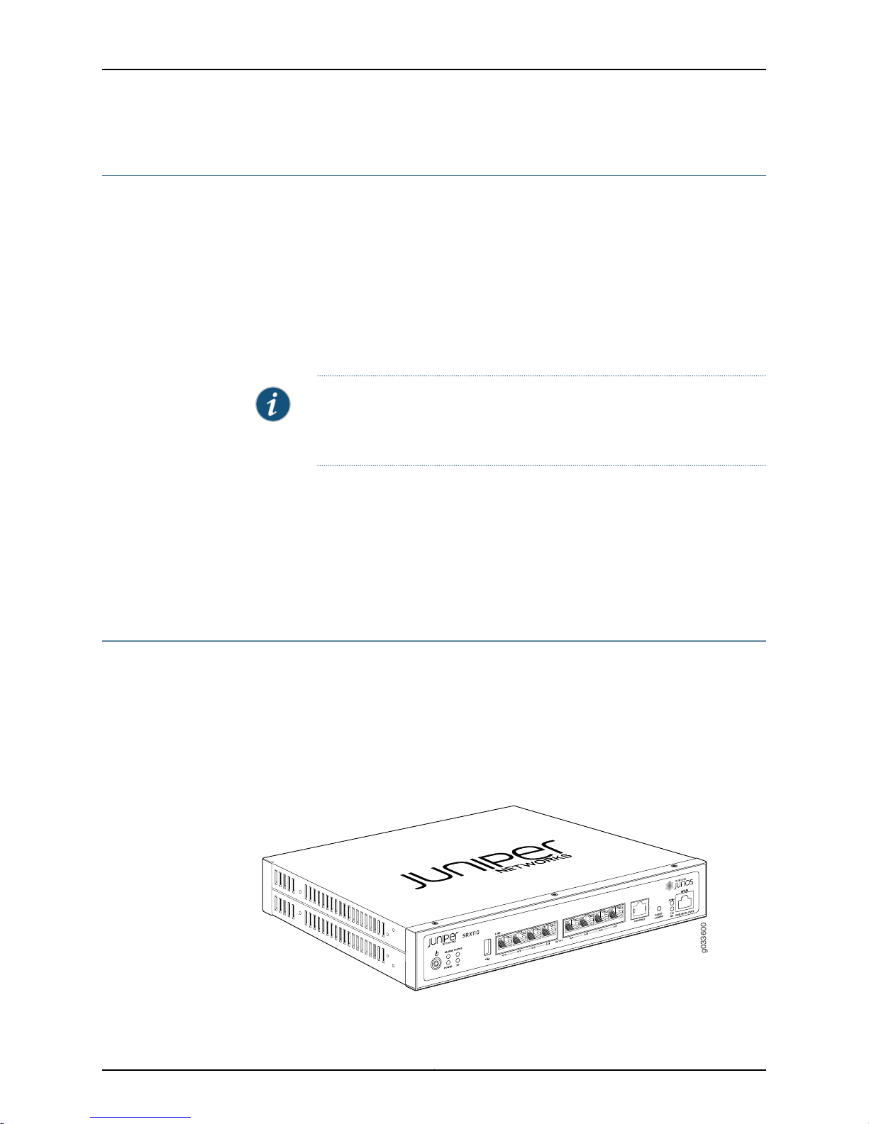
g033600
SRX110 Services Gateway Hardware Guide for H2 Model Numbers
General Site Guidelines for Installing the SRX110 Services Gateway
The following precautions help you plan an acceptable operating environment for your
services gateway and avoid environmentally caused equipment failures:
•
The SRX110 Services Gateway requires unrestricted circulation of air to maintain an
optimal operating temperature. Allow sufficient clearance between the front and back
of the chassis and adjacent equipment. Ensure that there is adequate circulation in
the installation location.
•
Followthe electrostaticdischarge (ESD) procedures to avoiddamaging theequipment.
Static discharge can cause components to fail completely or intermittently over time.
NOTE: Installthe device only in restricted areas, such as dedicatedequipment
rooms and equipment closets, in accordance with Articles 110–16, 110–17,
and 110–18 of the National Electrical Code, ANSI/NFPA 70.
Related
Documentation
SRX110 Services Gateway General Safety Guidelines and Warnings on page 131•
• SRX110 Services Gateway Rack Requirements on page 33
• SRX110 Services Gateway Cabinet Requirements on page 32
• Clearance Requirements for Airflow andHardware Maintenance of the SRX110Services
Gateway on page 34
SRX110 Services Gateway Specifications
The SRX110 Services Gateway chassis is a rigid sheet metal structure of 1 rack unit (U)
height, which houses all the other hardware components.
Figure 8 on page 30 shows the SRX110 Services Gateway with 3G and VDSL2
(VDSL/ADSL-POTS).
Figure 8: SRX110 Services Gateway with 3G and VDSL2
(VDSL/ADSL-POTS)
Copyright © 2015, Juniper Networks, Inc.30
Page 51
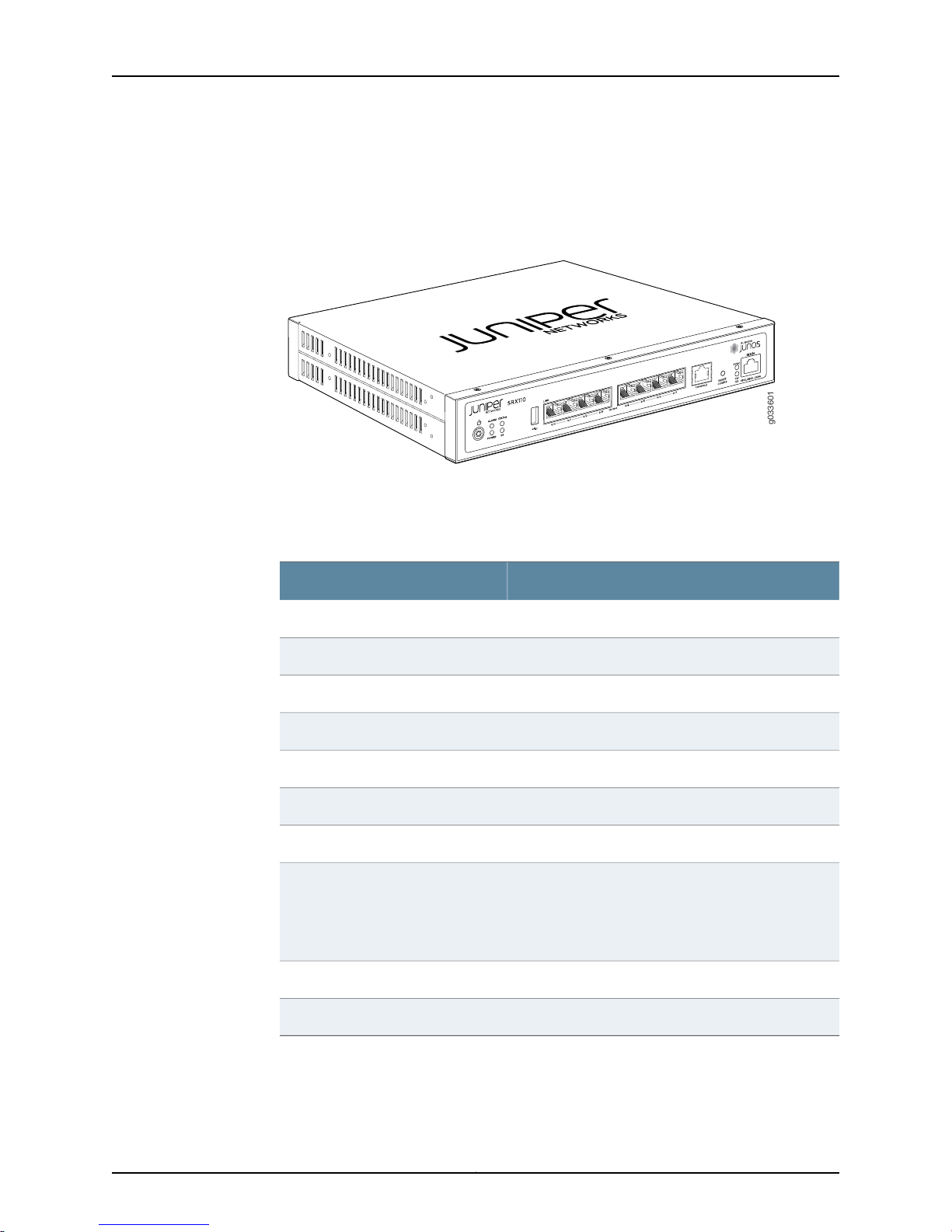
g033601
Chapter 4: Planning and Preparing the Site
Figure 9 on page 31 shows the SRX110 Services Gateway with 3G and VDSL2
(VDSL/ADSL-ISDN).
Figure 9: SRX110 Services Gateway with 3G and VDSL2
(VDSL/ADSL-ISDN)
Table 15 on page 31 provides information on the physical specifications of the SRX110
Services Gateway.
Table 15: SRX110 Services Gateway Specifications
ValueSpecification
1.7 in. (4.4 cm)Chassis height
11 in. (28 cm)Chassis width
8.4 in. (21.3 cm)Chassis depth
4.3 lb (1.962 kg)Chassis weight
24 WAverage power consumption
No performance degradation to 10,000 ft (3048 m)Altitude
5% to 90%, noncondensingRelative humidity
Temperature
Normal operation ensured in temperature range of 32°
F (0° C) to 104° F (+40° C)
Nonoperating storagetemperature inshipping container:
–40° F (–40° C) to 158° F (70° C)
99 BTU/hourMaximum thermal output
Related
SRX110 Services Gateway Description on page 3•
Documentation
< 15 dB(A) or less per EN ISO 7779Noise level
31Copyright © 2015, Juniper Networks, Inc.
Page 52
SRX110 Services Gateway Hardware Guide for H2 Model Numbers
• SRX110 Services Gateway Front Panel and Back Panel Views with 3G and Integrated
VDSL2 on page 15
• Monitoring the SRX110 Services Gateway Components Using LEDs on page 110
• SRX110 Services Gateway Electrical Safety Guidelines and Warnings on page 155
SRX110 Services Gateway 3G-WAN USB Port Physical Specifications
Table 16 on page 32 lists the physical specifications of the SRX110 Services Gateway
3G-WAN USB port.
Table 16: SRX110 Services Gateway 3G-WAN USB Port Physical
Specifications
ValueSpecification
5 VVoltage supply
Related
Documentation
Configuring the 3G USB Modem on the SRX110 Services Gateway on page 102•
• Installing a 3G USB Modem in the SRX110 Services Gateway USB Port on page 67
SRX110 Services Gateway Cabinet Requirements
The services gatewaycan be installed in a standard 31.5-in.(80.0-cm) or larger enclosed
cabinet.
Table 17 on page 32 provides the details on cabinet size, clearance, and airflow
requirements.
Table 17: SRX110 Services Gateway Cabinet Requirements
SpecificationsCabinet Requirement
Size
19 in. (48.3 cm) as defined in Cabinets, Racks, Panels, and
Associated Equipment (document number EIA-310–D)
published by the Electronics Industry Association
(http://www.eia.org).
0.5 ACurrent rating
2.5 WMaximum power consumption
You can mount the services gateway horizontally in the
cabinet.
Copyright © 2015, Juniper Networks, Inc.32
Page 53

Chapter 4: Planning and Preparing the Site
Table 17: SRX110 Services Gateway Cabinet Requirements (continued)
SpecificationsCabinet Requirement
•
Clearance
Airflow
The cabinet is at least 1 U (1.75 in. or 4.5 cm) high.
•
The outer edgesof themounting brackets extend thewidth
of either chassis to 19 in. (48.2 cm), and the front of the
chassis extends approximately 0.5 in. (1.27 cm) beyond the
mounting brackets.
•
The minimum total clearance inside the cabinet is 30.7 in.
(78 cm) between the inside of the front door and the inside
of the rear door.
NOTE: The holes for the mounting brackets for the chassis
are spaced 1.25 in. (3.2 cm) apart, measured from the center
of the hole.
•
Ensure that ventilation through the cabinet is sufficient to
prevent overheating.
•
Ensure that cool air supply is adequate to dissipate the
thermal output of the device.
•
Install the device as close as possible to the front of the
cabinet so that the cable management system clears the
inside of the front door. Installing the chassis close to the
front of the cabinet maximizes the clearance at the rear of
the cabinet for critical airflow.
•
Route and dress all cables to minimize the blockage of
airflow to and from the chassis.
NOTE: A cabinet larger than the minimum required size
provides better airflow andreduces the chance of overheating.
Related
Documentation
General Site Guidelines for Installing the SRX110 Services Gateway on page 30•
• SRX110 Services Gateway Rack Requirements on page 33
• Clearance Requirements for Airflow andHardware Maintenance of the SRX110Services
Gateway on page 34
SRX110 Services Gateway Rack Requirements
The services gateway can be installed in a rack. Many types of racks are acceptable,
including front-mount racks and four-post (telco) racks.
NOTE: The services gateway cannot be center mounted in a rack.
Table 18 on page 34 provides the details of requirements for rack size, clearance, airflow,
spacing of mounting brackets and flange holes, and connecting to the building structure.
33Copyright © 2015, Juniper Networks, Inc.
Page 54

SRX110 Services Gateway Hardware Guide for H2 Model Numbers
Table 18: Rack Requirements for the Services Gateway
SpecificationsRack Requirement
Related
Documentation
Size
Clearance
Spacing of Mounting
Bracket and Flange
Holes
Connecting to the
Building Structure
A 19in. (48.3 cm)rack as definedin Cabinets, Racks, Panels, and Associated
Equipment (document number EIA-310-D) published by the Electronics
Industry Association (http://www.eia.org).
•
The outer edges of the mounting brackets extend the width of either
chassis to 19 in. (48.3 cm).
•
The frontof the chassis extends approximately 0.5 in. (1.27 cm) beyond
the mounting ears.
•
Maximum permissible ambient temperature when two devices are
placed side by side in a 19 in. rack is 40° C.
•
The holes within each rack set are spaced at 1 U [1.75 in. (4.5 cm)]. The
device can be mounted in any rack that provides holes or hole patterns
spaced at 1-U [1.75 in. (4.5 cm)] increments.
•
The mounting brackets and front-mount flanges used to attach the
chassis to a rack are designed to fasten to holes spaced at rack
distances of 1 U (1.75 in.).
•
The mounting holes in the mounting brackets provided with the device
are spaced 1.25 in. (3.2 cm) apart (top and bottom mounting hole).
Always secure the rack in which you are installing the services gateway
to the structure of the building. If your geographical area is subject to
earthquakes, bolt the rack to the floor. For maximum stability, also secure
the rack to ceiling brackets.
General Site Guidelines for Installing the SRX110 Services Gateway on page 30•
• SRX110 Services Gateway Cabinet Requirements on page 32
• Clearance Requirements for Airflow andHardware Maintenance of the SRX110Services
Gateway on page 34
Clearance Requirementsfor Airflowand Hardware Maintenance of the SRX110 Services
Gateway
When planning the installation site for the services gateway, consider the following:
•
The SRX110 Services Gateway requires unrestricted circulation of air to maintain an
optimal operating temperature.
NOTE: The SRX110 Services Gateway does not include a fan and uses
natural convection cooling.
•
For service personnel to remove and install hardware components, there must be
adequate space at the front and back of the device. Allow at least 24 in. (61 cm) both
in front of and behind the device.
Copyright © 2015, Juniper Networks, Inc.34
Page 55
Chapter 4: Planning and Preparing the Site
•
If you are mounting the device in a rack with other equipment, or if you are placing it
on the desktop near other equipment, ensure that the exhaust from other equipment
does not blow into the intake vents of the chassis.
Table 19 on page 35 provides clearance requirements for maintaining optimum airflow
and for facilitating maintenance of the device.
Table 19: Clearance Requirements for the Services Gateway
Recommended
ClearanceLocation
Requirement for Clearance
Related
Documentation
2.5 in. (6.35 cm)Front of the chassis
2.5 in. (6.35 cm)Rear of the chassis
2.5 in. (6.35 cm)Between the front-mounting
flange and rack or cabinet edge
2.5 in. (6.35 cm)Betweenthe sideof thechassis
and any non-heat-producing
surface such as a wall or
cabinet side
2.5 in. (6.35 cm)Betweenthe sideof thechassis
and devices that have fans or
blowers
• General Site Guidelines for Installing the SRX110 Services Gateway on page 30
• SRX110 Services Gateway Cabinet Requirements on page 32
• SRX110 Services Gateway Rack Requirements on page 33
Space for service personnel to
remove and install hardware
components
Space for service personnel to
remove and install hardware
components
Space for cable management and
organization
Space for the cooling system to
function properly and to maintain
unrestricted airflow around the
chassis
Space for the cooling system to
function properly and to maintain
unrestricted airflow around the
chassis
35Copyright © 2015, Juniper Networks, Inc.
Page 56

SRX110 Services Gateway Hardware Guide for H2 Model Numbers
Copyright © 2015, Juniper Networks, Inc.36
Page 57
CHAPTER 5
Power Requirements and Specifications
•
SRX110 Services Gateway Site Electrical Wiring Guidelines on page 37
•
SRX110 Services Gateway Electrical and Power Requirements on page 38
•
SRX110 Services Gateway Power Specifications and Requirements on page 39
SRX110 Services Gateway Site Electrical Wiring Guidelines
Table 20 onpage 37 describes thefactorsyou mustconsider while planningthe electrical
wiring for the services gateway at your site.
CAUTION: It is particularly important to provide a properly grounded and
shielded environment and to use electrical surge-suppression devices.
CAUTION: For devices with AC power supplies, an external surge protective
device (SPD) must be used at the AC power source.
Table 20: Site Electrical Wiring Guidelines for the Services Gateway
GuidelineSite Wiring Factor
Signaling Limitations
To ensure that signaling functions optimally:
•
Install wires correctly.
Improperly installed wires can emit radio interference.
•
Do not exceed the recommended distances or pass wires
between buildings.
The potentialfor damage from lightningstrikes increases if wires
exceed recommended distances or if wires pass between
buildings.
•
Shield all conductors.
The electromagnetic pulse (EMP) caused by lightning can
damage unshielded conductors and destroy electronic devices.
37Copyright © 2015, Juniper Networks, Inc.
Page 58
SRX110 Services Gateway Hardware Guide for H2 Model Numbers
Table 20: Site Electrical Wiring Guidelines for the Services
Gateway (continued)
GuidelineSite Wiring Factor
Radio Frequency
Interference (RFI)
Electromagnetic
Compatibility (EMC)
CAUTION: To comply with intrabuilding lightning/surge requirements, the
intrabuilding wiring must be shielded. The shielding for the wiring must be
grounded at both ends.
To reduce or eliminate the emission of RFI from your site wiring:
•
Use twisted-pair cable with a good distribution of grounding
conductors.
•
Use a high-quality twisted-paircable withone ground conductor
for each data signal when applicable, if you must exceed the
recommended distances.
Provide a properly grounded and shielded environment and use
electrical surge-suppression devices.
Strong sources of electromagnetic interference (EMI) can cause
the following damage:
•
Destroy the signal drivers and receivers in the device
•
Conduct power surges over thelines into theequipment, resulting
in an electrical hazard
NOTE: If your site is susceptible to problems with EMC,particularly
from lightning or radio transmitters, you may want to seek expert
advice.
Related
Documentation
General Site Guidelines for Installing the SRX110 Services Gateway on page 30•
• SRX110 Services Gateway Power Specifications and Requirements on page 39
SRX110 Services Gateway Electrical and Power Requirements
You must consider the following factors while planning the electrical wiring and power
availability at your site:
•
Power specifications and requirements for the device
•
Electrical wiring guidelines for the device installation site
•
Power, connection, and power cord specifications for the device
•
Grounding guidelines and specifications for the device
Related
Documentation
SRX110 Services Gateway Site Electrical Wiring Guidelines on page 37•
• Clearance Requirements for Airflow andHardware Maintenance of the SRX110Services
Gateway on page 34
Copyright © 2015, Juniper Networks, Inc.38
Page 59
Chapter 5: Power Requirements and Specifications
SRX110 Services Gateway Power Specifications and Requirements
The AC powersystem electrical specifications for the SRX110 ServicesGateway are listed
in Table 21 on page 39.
Table 21: Power Supply Electrical Specifications for the SRX110 Services
Gateway
SpecificationPower Requirement
100 to 240 VACAC input voltage
50 to 60 HzAC input line frequency
1.5 A maximumAC system current rating
WARNING: The AC power cord for the services gateway is intended for use
with the device only and not for any other use.
Related
Documentation
• SRX110 Services Gateway Electrical Safety Guidelines and Warnings on page 155
• SRX110 Services Gateway Power Supply on page 9
• SRX110 Services Gateway Grounding Specifications on page 71
39Copyright © 2015, Juniper Networks, Inc.
Page 60

SRX110 Services Gateway Hardware Guide for H2 Model Numbers
Copyright © 2015, Juniper Networks, Inc.40
Page 61

CHAPTER 6
Cable Specifications and Pinouts
•
Interface Cable and Wire Specifications for the SRX110 Services Gateway on page 41
•
RJ-45 Connector Pinouts for the SRX110 Services Gateway Ethernet Port on page 42
•
RJ-45 Connector Pinouts for the SRX110 Services Gateway Console Port on page 43
•
RJ-11 Connector Pinouts for the SRX110 Services Gateway on page 44
Interface Cable and Wire Specifications for the SRX110 Services Gateway
Table 22 on page 41 lists the specifications for the cables that connect to ports.
Table 22: Cable and Wire Specifications for Ports
Maximum
LengthCable/Wire RequiredCableSpecificationPort
DeviceReceptacle
Related
Documentation
Console
port
Ethernet
port
VDSL2
port
RS-232 (EIA-232)
serial cable
CAT-5e (Category 5)
cable or equivalent
suitable for
100BASE-T
operation
•
For
VDSL/ADSL-POTS:
RJ-11 cable
•
For
VDSL/ADSL-ISDN:
RJ-11/RJ-45 cable
One 6 ft (1.83 m) length
with DB-9/RJ-45
connectors
One 15 ft (4.57 m)
length with RJ-45/RJ-45
connectors
•
For
VDSL/ADSL-POTS:
One 10 ft (3.048 m)
with RJ-11 connector
•
For
VDSL/ADSL-ISDN:
One 10 ft (3.048 m)
with RJ-45 connector
(1.83 m)
(100 m)
18K ft
(5.486K
m)
RJ-456 ft
RJ-45328 ft
•
For
VDSL/ADSL-POTS:
RJ-11
•
For
VDSL/ADSL-ISDN:
RJ-45
RJ-45 Connector Pinouts for the SRX110 Services Gateway Ethernet Port on page 42•
• RJ-45 Connector Pinouts for the SRX110 Services Gateway Console Port on page 43
• RJ-11 Connector Pinouts for the SRX110 Services Gateway on page 44
41Copyright © 2015, Juniper Networks, Inc.
Page 62
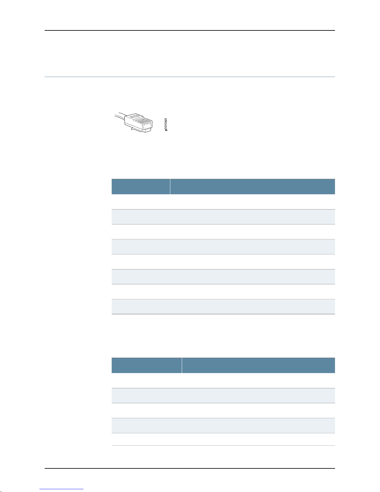
SRX110 Services Gateway Hardware Guide for H2 Model Numbers
RJ-45 Connector Pinouts for the SRX110 Services Gateway Ethernet Port
Figure 10 on page 42 shows the RJ-45 cable connector pinouts for Ethernet ports.
Figure 10: Ethernet Cable Connector (RJ-45)
Table 23 on page 42 describes the RJ-45 connector pinouts for the Ethernet port for
10/100 Mbps.
Table 23: RJ-45 Connector Pinouts for the Services Gateway Ethernet
Port (10/100 Mbps)
SignalPin
TX+1
TX-2
RX+3
Termination network4
Termination network5
RX-6
Termination network7
Termination network8
Table 24 on page 42 describes the RJ-45 connector pinouts for the Ethernet port for 1
Gbps (1000 Mbps).
Table 24: RJ-45 Connector Pinouts for the Services Gateway Ethernet
Port (1 Gbps)
SignalPin
BI_DA+1
BI_DA-2
BI_DB+3
BI_DC+4
BI_DC-5
Copyright © 2015, Juniper Networks, Inc.42
Page 63
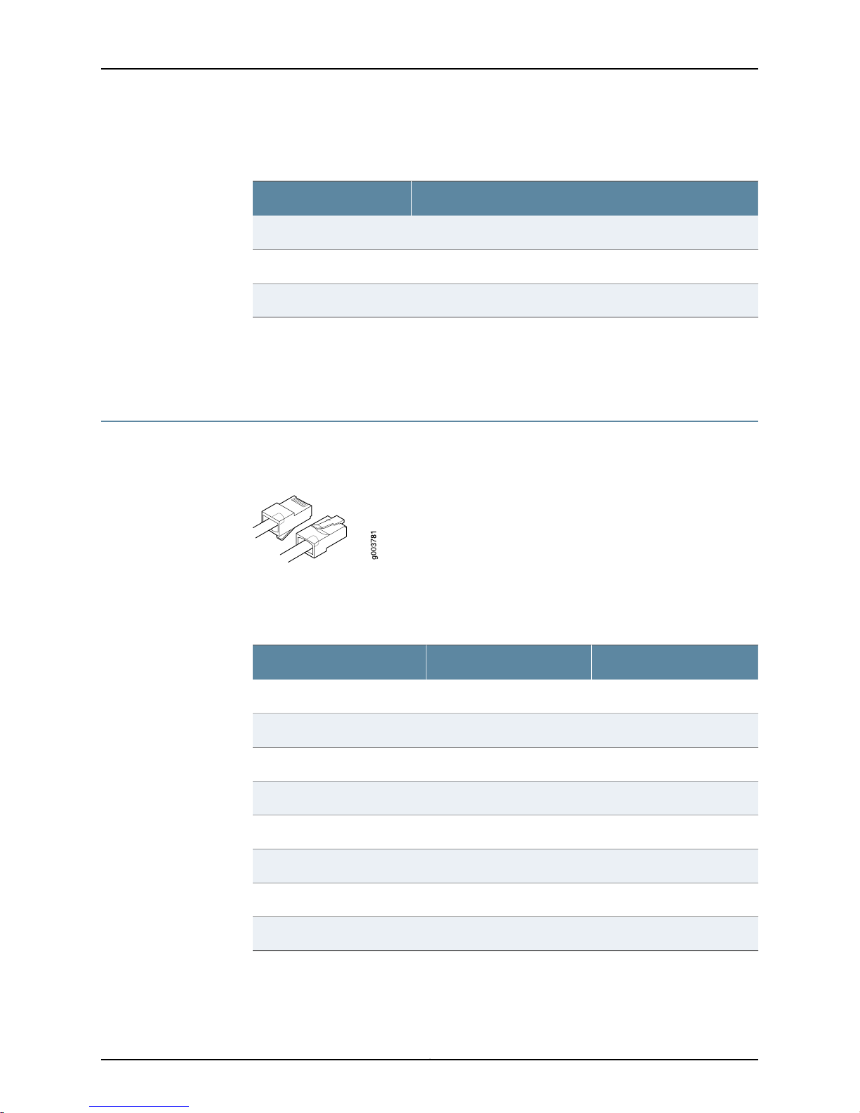
Chapter 6: Cable Specifications and Pinouts
Table 24: RJ-45 Connector Pinouts for the Services Gateway Ethernet
Port (1 Gbps) (continued)
SignalPin
BI_DB-6
BI_DD+7
BI_DD-8
Related
Documentation
Interface Cable and Wire Specifications for the SRX110 Services Gateway on page 41•
• RJ-45 Connector Pinouts for the SRX110 Services Gateway Console Port on page 43
RJ-45 Connector Pinouts for the SRX110 Services Gateway Console Port
Figure 11 on page 43 shows the RJ-45 connector pinouts for the console port.
Figure 11: Console Cable Connector
Table 25 on page 43 describes the RJ-45 connector pinouts for the console port.
Table 25: RJ-45 Connector Pinouts for the Services Gateway Console
Port
DescriptionSignalPin
Request to SendRTS1
Data Terminal ReadyDTR2
Transmit DataTXD3
Signal GroundGround4
Signal GroundGround5
Receive DataRXD6
Data Set ReadyDSR/DCD7
Clear to SendCTS8
43Copyright © 2015, Juniper Networks, Inc.
Page 64
SRX110 Services Gateway Hardware Guide for H2 Model Numbers
Related
Documentation
Connecting and Organizing the SRX110 Services Gateway Interface Cables on page 75•
• Interface Cable and Wire Specifications for the SRX110 Services Gateway on page 41
RJ-11 Connector Pinouts for the SRX110 Services Gateway
Table 26 on page 44 describes the RJ-11 connector pinouts for the VDSL2 port.
Table 26: RJ-11 Connector Pinouts
SignalPin
No connect1
No connect2
RJ P –Ring3
RJ N –Tip4
No connect5
No connect6
Related
Documentation
• Connecting and Organizing the SRX110 Services Gateway Interface Cables on page 75
• Interface Cable and Wire Specifications for the SRX110 Services Gateway on page 41
Copyright © 2015, Juniper Networks, Inc.44
Page 65

PART 3
Initial Installation and Configuration
•
Installation Overview on page 47
•
Unpacking the Services Gateway on page 51
•
Installing the Mounting Hardware on page 55
•
Installing the Services Gateway on page 59
•
Grounding the SRX110 Services Gateway on page 71
•
Connecting the SRX110 Services Gateway to External Devices on page 75
•
Providing Power to the SRX110 Services Gateway on page 79
•
Performing Initial Configuration on page 83
45Copyright © 2015, Juniper Networks, Inc.
Page 66

SRX110 Services Gateway Hardware Guide for H2 Model Numbers
Copyright © 2015, Juniper Networks, Inc.46
Page 67

CHAPTER 7
Installation Overview
•
Installation Overview for the SRX110 Services Gateway on page 47
•
Required Tools and Parts for Installing and Maintaining the SRX110 Services
Gateway on page 48
•
SRX110 Services Gateway Autoinstallation Overview on page 49
Installation Overview for the SRX110 Services Gateway
After you prepare your installation site, you are ready to unpack and install the services
gateway. It is important to perform the installation procedure as indicated in
Table 27 on page 47.
Table 27: Installation Procedure for the SRX110 Services Gateway
Additional InformationTaskStep
Review the safety guidelines.1
Verify that you have prepared your
2
site for the installation of the
services gateway in accordance
with the checklist.
Unpack the services gateway and
3
verify that all parts are received.
Prepare the services gateway for
4
installation.
Install the services gateway.5
“SRX110 Services Gateway General Safety
Guidelines and Warnings” on page 131
Site Preparation Checklist for the SRX110 Services
Gateway
“Unpacking the SRX110 Services Gateway” on
page 51
Preparing the SRX110 Services Gateway for
Rack-Mount, Desk-Mount, and Wall-Mount
Installation
“Installing the SRX110 Services Gateway in a Rack”
on page 59
“Installing theSRX110 Services Gatewayon aDesk”
on page 63
“Installing theSRX110 Services Gatewayon aWall”
on page 65
47Copyright © 2015, Juniper Networks, Inc.
Page 68

SRX110 Services Gateway Hardware Guide for H2 Model Numbers
Table 27: Installation Procedure for the SRX110 Services
Gateway (continued)
Additional InformationTaskStep
“Connecting and Organizing the SRX110 Services
Gateway Interface Cables” on page 75
“Grounding the SRX110 Services Gateway” on
page 72
“Powering On the SRX110 Services Gateway” on
page 80
“Powering Off the SRX110 Services Gateway” on
page 81
Related
Documentation
Connect cables to external devices.6
Connect the grounding cables.7
Power on the services gateway.8
Unpacking the SRX110 Services Gateway on page 51•
• General Site Guidelines for Installing the SRX110 Services Gateway on page 30
• Preparing the SRX110 Services Gateway for Rack-Mount, Desk-Mount, and Wall-Mount
Installation
Required Tools and Parts for Installing and Maintaining the SRX110 Services Gateway
Table 28 onpage 48 lists the tools and equipments required for installing and maintaining
the SRX110 Services Gateway.
Table 28: Required Tools and Parts for Installing and Maintaining the
SRX110 Services Gateway
Installing the SRX110
Services Gateway
Connecting the
SRX110 Services
Gateway
Grounding the SRX110
Services Gateway
•
Phillips (+) screwdriver,
number 1
•
Phillips (+) screwdriver,
number 3
•
Tie wrap
Electrostatic discharge (ESD)
grounding wrist strap
Phillips (+) screwdriver,
number 1
Additional InformationTools and PartsTask
“Installing the SRX110 Services
Gateway in a Rack” on page 59
“Installing the SRX110 Services
Gateway on a Desk” on page 63
“Installing the SRX110 Services
Gateway on a Wall” on page 65
“Connecting the SRX110 Services
Gateway to the Power Supply” on
page 79
“Grounding the SRX110 Services
Gateway” on page 72
Copyright © 2015, Juniper Networks, Inc.48
Page 69

Chapter 7: Installation Overview
Table 28: Required Tools and Parts for Installing and Maintaining the
SRX110 Services Gateway (continued)
Additional InformationTools and PartsTask
•
Electrostatic bag or
antistatic mat, for each
component
•
Electrostatic discharge
(ESD) grounding wrist strap
Related
Documentation
Packing the SRX110
Services Gateway
Unpacking the SRX110 Services Gateway on page 51•
• Grounding the SRX110 Services Gateway on page 72
• Connecting the SRX110 Services Gateway to the Power Supply on page 79
• Packing the SRX110 Services Gateway and Components for Shipment on page 125
SRX110 Services Gateway Autoinstallation Overview
The autoinstallation process begins any time a services gateway is powered on and
cannot locate a valid configuration file in the internal flash memory device. Typically, a
configuration file is unavailable when a services gateway is powered on for the first time
or if the configuration file is deleted from the internal flash memory device.
The autoinstallation feature enables you to deploy multiple services gateways from a
central location in the network.
If you are setting up many devices, autoinstallation can help automate the configuration
process by loading configuration files onto new or existing devices automatically over
the network. You can use either the J-Web configuration editor or the command-line
interface (CLI) configuration editor to configure a device for autoinstallation.
“Packingthe SRX110ServicesGateway
and Components for Shipment” on
page 125
For the autoinstallation process to work, you must store one or more host-specific or
default configuration files on a configuration server in the network and have a service
available—typicallyDynamic HostConfigurationProtocol(DHCP)—to assign anIP address
to the services gateway.
Autoinstallation occurs automatically when you connect an Ethernet port on a new
services gateway to the network and power on the device. To simplify the process, you
can explicitly enable autoinstallation on a device and specify a configuration server, an
autoinstallation interface, and a protocol for IP address acquisition.
For more information about configuring autoinstallation, see the following topics:
•
Initial Configuration for Security Devices
•
Monitoring and Troubleshooting for Security Devices
Related
Documentation
• Connecting the SRX110 Services Gateway to the Power Supply on page 79
• Grounding the SRX110 Services Gateway on page 72
49Copyright © 2015, Juniper Networks, Inc.
Page 70

SRX110 Services Gateway Hardware Guide for H2 Model Numbers
• Powering On the SRX110 Services Gateway on page 80
• Powering Off the SRX110 Services Gateway on page 81
• SRX110 Services Gateway Software Configuration Overview on page 83
Copyright © 2015, Juniper Networks, Inc.50
Page 71

CHAPTER 8
Unpacking the Services Gateway
•
Unpacking the SRX110 Services Gateway on page 51
•
Verifying Parts Received with the SRX110 Services Gateway on page 51
Unpacking the SRX110 Services Gateway
The SRX110 Services Gateway is shipped in a cardboard carton. The carton also contains
an accessory box and the SRX110 Services Gateway Quick Start.
NOTE: The device is maximally protected inside the shipping carton. Do not
unpack it until you are ready to begin installation.
To unpack the services gateway:
1. Open the box in which the device is shipped.
2. Verify the parts received against the packing list in Verifying Parts Received with the
SRX110 Services Gateway.
3. Store the shipping box and packing material in case you need to return or move the
device at a later time.
Related
Documentation
Required Tools and Parts for Installing and Maintaining the SRX110 Services Gateway
•
on page 48
• Preparing the SRX110 Services Gateway for Rack-Mount, Desk-Mount, and Wall-Mount
Installation
• Installation Overview for the SRX110 Services Gateway on page 47
Verifying Parts Received with the SRX110 Services Gateway
The services gateway shipment package contains a packing list that includes all parts
and accessories available with the device. Check the parts in the shipment against the
items on the packing list. The packing list specifies the part numbers and descriptions of
each part in your order.
If any part is missing, contact your Juniper Networks customer service representative.
51Copyright © 2015, Juniper Networks, Inc.
Page 72
SRX110 Services Gateway Hardware Guide for H2 Model Numbers
A fully configured SRX110 Services Gateway contains the chassis with installed
components, listed in Table 29 on page 52, and an accessory box, which contains the
parts listed in Table 30 on page 52.
NOTE: The parts shipped with your device can vary depending on the
configuration you ordered.
Table 29: Parts List for a Fully Configured SRX110 Services Gateway
and base memory (2 GB RAM, 2 GB Flash)
QuantityPart
1SRX110 Services Gateway with 8xFE ports, 1xUSB port, 1x3G-WAN USB port,
1Power supply adapter of 60 W
13-Prong Power Cord
1DB-9 to RJ-45 Adapter, Straight Through, 7 feet
1Extension cable for 3G USB modem
Table 30: Accessory Parts List for the SRX110 Services Gateway
QuantityPart
1Juniper Networks Product Warranty
1End User License Agreement
1Quick Start Guide
1Security Products Safety Guide
1Juniper Compliance Form Letter
1Product Registration
NOTE: The mounting kits available for rack, wall, and desk installationof the
SRX110 Services Gateway must be ordered separately. Contact your Juniper
Networks customer service representative for more information.
Related
Documentation
• Required Tools and Parts for Installing and Maintaining the SRX110 Services Gateway
on page 48
• Unpacking the SRX110 Services Gateway on page 51
Copyright © 2015, Juniper Networks, Inc.52
Page 73

Chapter 8: Unpacking the Services Gateway
• Preparing the SRX110 Services Gateway for Rack-Mount, Desk-Mount, and Wall-Mount
Installation
53Copyright © 2015, Juniper Networks, Inc.
Page 74

SRX110 Services Gateway Hardware Guide for H2 Model Numbers
Copyright © 2015, Juniper Networks, Inc.54
Page 75
CHAPTER 9
Installing the Mounting Hardware
•
Preparing the SRX110 Services Gateway for Rack-Mount Installation on page 55
•
Preparing the SRX110 Services Gateway for Desk-Mount Installation on page 56
•
Preparing the SRX110 Services Gateway for Wall-Mount Installation on page 57
Preparing the SRX110 Services Gateway for Rack-Mount Installation
You can mount an SRX110 Services Gateway on 4-post (telco) racks, enclosed cabinets,
and open-frame racks.
NOTE: The SRX110 Services Gateway cannot be center-mounted in a rack.
Table 31 on page 55 lists the tasks you need to perform before installing the device.
Table 31: SRX110 Services Gateway Preinstallation Checklist for
Rack-Mount Installation
Verify that the site meets the requirements.
Verify that the racks or cabinets meet the specific
requirements.
Place the rack or cabinet in its permanent location,
allowing adequate clearance for airflow and
maintenance,and secureit to thebuilding structure.
Remove the services gateway chassis from the
shipping carton.
Additional InformationTask
Site Preparation Checklist for the SRX110
Services Gateway
“SRX110 Services Gateway Rack
Requirements” on page 33
“Clearance Requirements for Airflow and
Hardware Maintenance of the SRX110
Services Gateway” on page 34
“Unpacking the SRX110 Services Gateway”
on page 51
55Copyright © 2015, Juniper Networks, Inc.
Page 76
SRX110 Services Gateway Hardware Guide for H2 Model Numbers
Table 31: SRX110 Services Gateway Preinstallation Checklist for
Rack-Mount Installation (continued)
Verify that you have the following parts available
in your rack-mounting kit for the SRX110 Services
Gateway:
•
Rack-mounting brackets
•
Mounting screws
•
Power supply adapter tray with screws
•
Adapter stopper bracket
Additional InformationTask
Adjust the power supply adapter tray.
“Adjusting the Power Supply Adapter Tray
for the SRX110 Services Gateway for
Rack-Mount Installation” on page 62
NOTE: The rack-mounting kit is not shipped with the device and must be
ordered separately.
Related
Documentation
Unpacking the SRX110 Services Gateway on page 51•
• Clearance Requirements for Airflow andHardware Maintenance of the SRX110Services
Gateway on page 34
• Preparing the SRX110 Services Gateway for Desk-Mount Installation on page 56
• Preparing the SRX110 Services Gateway for Wall-Mount Installation on page 57
Preparing the SRX110 Services Gateway for Desk-Mount Installation
You can mount the services gateway on a desk or other level surface horizontally or
vertically. The four rubber feet attached to the chassis provide stability.
Table 32 on page 56 provides the list of tasks you need to perform before installing the
device.
Table 32: SRX110 Services Gateway Preinstallation Checklist for
Desk-Mount Installation
Verify that the site meets the requirements.
Place the desk in its permanent location, allowing
adequateclearance forairflowand maintenance, and
secure it to the building structure.
Additional InformationTask
Site Preparation Checklist for the SRX110
Services Gateway
“Clearance Requirements for Airflow and
Hardware Maintenance of the SRX110
Services Gateway” on page 34
Copyright © 2015, Juniper Networks, Inc.56
Page 77
Chapter 9: Installing the Mounting Hardware
Table 32: SRX110 Services Gateway Preinstallation Checklist for
Desk-Mount Installation (continued)
Additional InformationTask
Related
Documentation
Remove the services gateway chassis from the
shipping carton.
Verify that you have the following parts available in
your desk-mounting kitto mountthe SRX110Services
Gateway vertically:
•
Vertical stand
•
Screws
“Unpacking the SRX110 Services
Gateway” on page 51
NOTE: If you are mounting the servicesgatewayhorizontallyon a desk, ensure
that the rubber feet are attached to the chassis.
NOTE: The vertical desk-mounting kit is not shipped with the device and
must be ordered separately.
Unpacking the SRX110 Services Gateway on page 51•
• Clearance Requirements for Airflow andHardware Maintenance of the SRX110Services
Gateway on page 34
• Preparing the SRX110 Services Gateway for Rack-Mount Installation on page 55
• Preparing the SRX110 Services Gateway for Wall-Mount Installation on page 57
Preparing the SRX110 Services Gateway for Wall-Mount Installation
You can mount an SRX110 Services Gateway on a wall. The four rubber feet attached to
the chassis provide stability.
Table 33 on page 57 provides the list of tasks you need to perform before installing the
device.
Table 33: SRX110 Services Gateway Preinstallation Checklist for
Wall-Mount Installation
Additional InformationTask
Verify that the site meets the requirements.
Removethe services gatewaychassis from theshipping
carton.
Site Preparation Checklist for the SRX110
Services Gateway
“Unpacking the SRX110 Services
Gateway” on page 51
57Copyright © 2015, Juniper Networks, Inc.
Page 78
SRX110 Services Gateway Hardware Guide for H2 Model Numbers
Table 33: SRX110 Services Gateway Preinstallation Checklist for
Wall-Mount Installation (continued)
Verifythat you havethe following partsavailable in your
wall-mounting kit to mount the SRX110 Services
Gateway on a wall:
•
Wall-mounting brackets
•
Screws
NOTE: The wall-mounting kit is not shipped with the device and must be
ordered separately.
Additional InformationTask
Related
Documentation
• Unpacking the SRX110 Services Gateway on page 51
• Clearance Requirements for Airflow andHardware Maintenance of the SRX110Services
Gateway on page 34
• Preparing the SRX110 Services Gateway for Rack-Mount Installation on page 55
• Preparing the SRX110 Services Gateway for Desk-Mount Installation on page 56
Copyright © 2015, Juniper Networks, Inc.58
Page 79

CHAPTER 10
Installing the Services Gateway
•
Installing the SRX110 Services Gateway in a Rack on page 59
•
Adjusting the Power Supply Adapter Tray for the SRX110 Services Gateway for
Rack-Mount Installation on page 62
•
Installing the SRX110 Services Gateway on a Desk on page 63
•
Installing the SRX110 Services Gateway on a Wall on page 65
•
Installing a 3G USB Modem in the SRX110 Services Gateway USB Port on page 67
Installing the SRX110 Services Gateway in a Rack
You can front-mount the SRX110 Services Gateway in a rack. Many types of racks are
acceptable, including 4-post (telco) racks, enclosed cabinets, and open-frame racks.
For moreinformation about the type of rack orcabinet that the SRX110 ServicesGateway
can be installed into, see “SRX110 Services Gateway Rack Requirements” on page 33.
NOTE: The rack-mounting kit is not shipped with the device and must be
ordered separately.
NOTE:
•
If you are installing multiple devices in one rack, install the first device in
the lowest position in the rack and proceed upward in the rack.
•
Ensure that the rubber feet on the base of the chassis are removed for rack
installation.
59Copyright © 2015, Juniper Networks, Inc.
Page 80
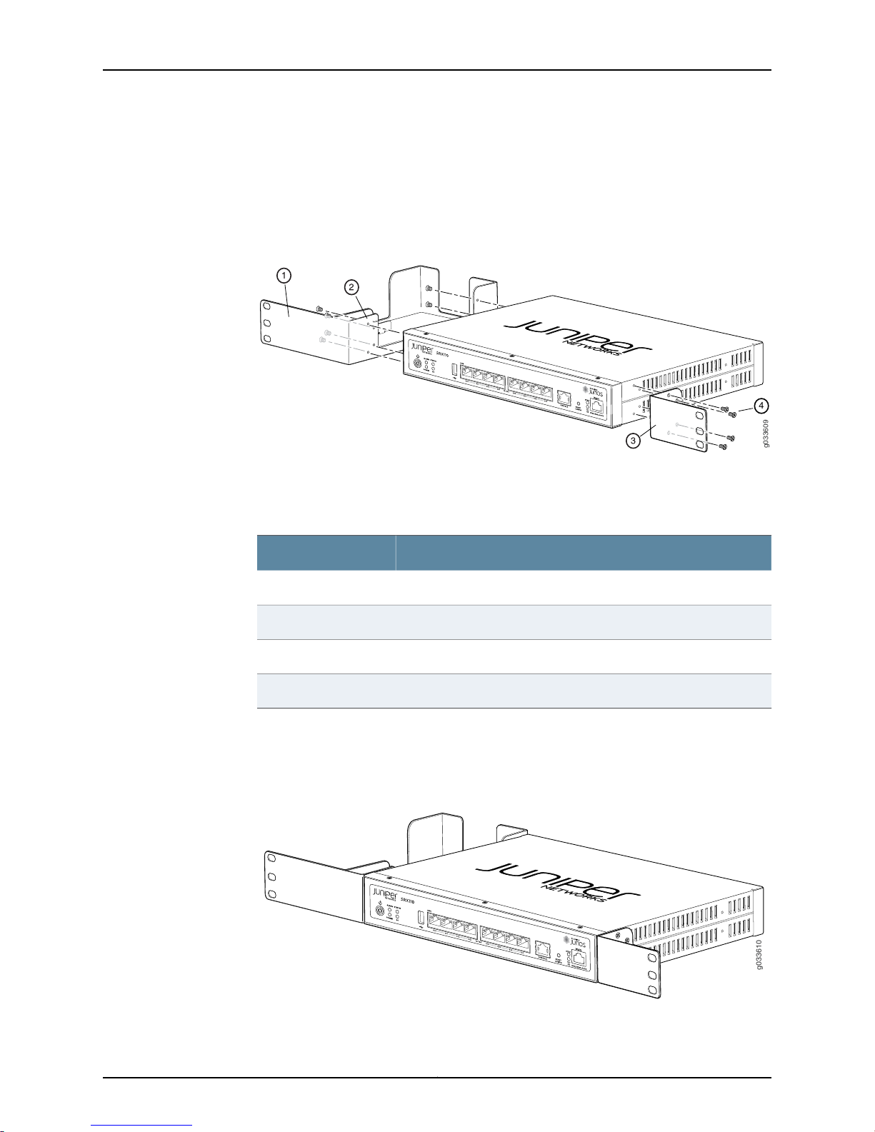
g033609
4
g033610
SRX110 Services Gateway Hardware Guide for H2 Model Numbers
To install the device in a rack:
1. Position a mounting bracket on each side of the chassis as shown in
Figure 12 on page 60.
Figure 12: SRX110 Services Gateway Installation in a Rack — Positioning
Mounting Brackets
Table 34 on page 60 lists the parts used for installing the device on the rack. The
numbers in Figure 12 on page 60 correspond to the numbers in Table 34 on page 60.
Table 34: SRX Services Gateway Rack Installation Parts
PartNumber
Power supply adapter tray1
Adapter stopper bracket2
Mounting brackets3
Screws (mounting bracket)4
2. Use a Phillips(+) screwdriver, number1, to installthe screws that securethe mounting
bracketsand power supply adapter tray to thechassis as shown inFigure 13on page 60.
Figure 13: SRX110 Services GatewayRack Installation— Securing Mounting
Brackets and Power Supply Adapter Tray
Copyright © 2015, Juniper Networks, Inc.60
Page 81
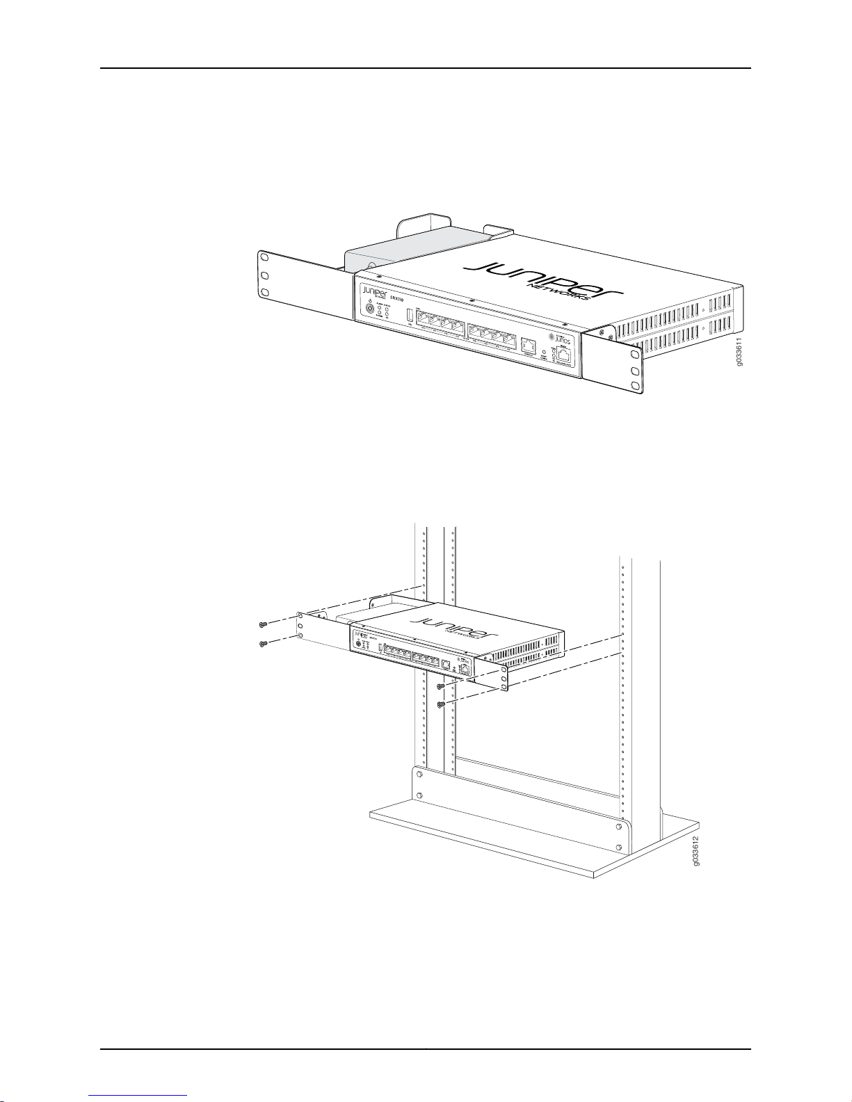
g033611
g033612
Chapter 10: Installing the Services Gateway
3. Place the power supply adapter in the tray as shown in Figure 14 on page 61.
Figure 14: SRX110 Services Gateway Rack Installation — Positioning Power
Supply Adapter Tray
4. Have one person grasp the sides of the device, lift it, and position it in the rack.
5. Align the bottom hole in each mounting bracket with a hole in each rack rail as shown
in Figure 15 on page 61, making sure that the chassis is level.
Figure 15: SRX110 Services Gateway Rack Installation — Hanging the
Services Gateway in a Rack
6. Have a second person install a mounting screw into each of the two aligned holes.
Use a Phillips (+) screwdriver, number 3, to tighten the screws.
61Copyright © 2015, Juniper Networks, Inc.
Page 82
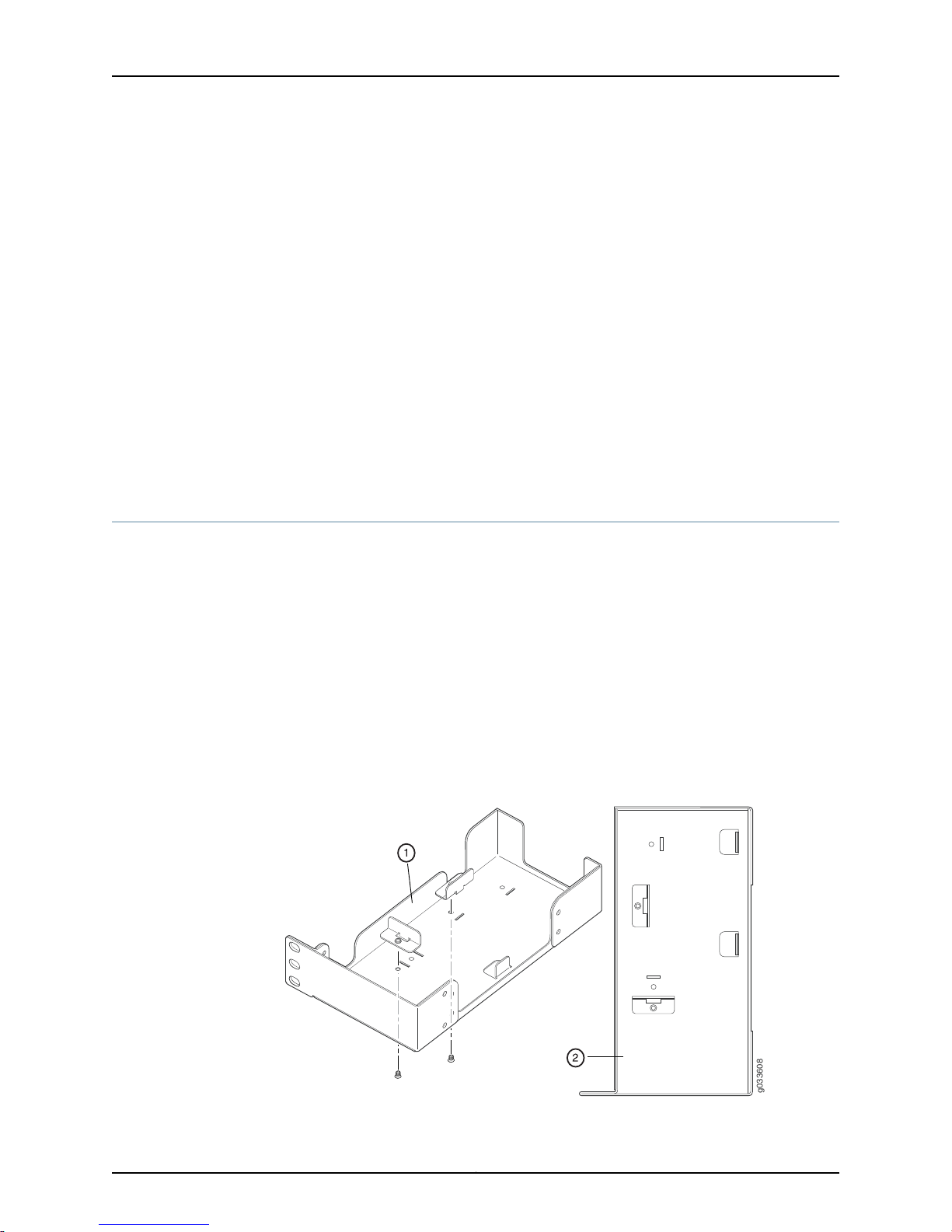
g033608
SRX110 Services Gateway Hardware Guide for H2 Model Numbers
7. Install the second screw in each mounting bracket.
8. Verify that the mounting screws on one side of the rack are aligned with the mounting
screws on the opposite side and that the device is level.
Related
Documentation
SRX110 Services Gateway Installation Safety Guidelines and Warnings on page 139•
• Required Tools and Parts for Installing and Maintaining the SRX110 Services Gateway
on page 48
• SRX110 Services Gateway General Safety Guidelines and Warnings on page 131
• Preparing the SRX110 Services Gateway for Rack-Mount Installation on page 55
• Adjusting the Power Supply Adapter Tray for the SRX110 Services Gateway for
Rack-Mount Installation on page 62
• Installing the SRX110 Services Gateway on a Desk on page 63
Adjusting the Power Supply Adapter Tray for the SRX110 Services Gateway for
Rack-Mount Installation
This topic provides detailson the power supply adapter forthe SRX110 Services Gateway
and the procedure for adjusting the power supply adapter tray to hold the power supply
adapter.
A 60-watt power supply adapter is provided with the SRX110 Services Gateway.
To accommodate the 60-watt power supply, use the two 420–028535 screws to attach
the adapter stopper brackets at the point on the chassis marked B.
Figure 16 on page 62 shows the adjustments to the power supply adapter tray required
for the 60-watt power supply.
Figure 16: Adjusting the Power Supply Adapter Tray to Accommodate the
60-Watt Power Supply
Copyright © 2015, Juniper Networks, Inc.62
Page 83

Chapter 10: Installing the Services Gateway
1. Locations for the adapter stopper brackets in the power supply adapter tray
2. Fully configured power supply adapter tray
Related
Documentation
Preparing the SRX110 Services Gateway for Rack-Mount, Desk-Mount, and Wall-Mount
•
Installation
• SRX110 Services Gateway Power Supply on page 9
Installing the SRX110 Services Gateway on a Desk
Follow these guidelines when installing the device on a desk:
•
You can install the SRX110 Services Gateway on a desk, table, or other level surface.
•
The device is shipped with the rubber feet attached. The rubber feet are necessary to
stabilize the device on the desk.
•
You can install the device in a horizontal or vertical position.
•
The vertical position requires the vertical installation kit, which consists of a vertical
installation stand with the rubber feet attached.
NOTE: The desk-mounting kit is not shipped with the device and must be
ordered separately.
To install the device in a horizontal position:
The horizontal position is the standard installation position and does not require the
vertical installation kit.
1. Make sure that the rubber feet are attached to the chassis.
2. Place the device on a desk with the Juniper Networks logo facing up. The logo is
embossed on the top cover.
To install the device in a vertical position:
1. Place the device on a flat and level surface, with the Juniper Networks logo facing up.
The logo is embossed on the top cover.
2. Attach the vertical stand to the right side of the chassis, using the specified screws
as shown in Figure 17 on page 64.
63Copyright © 2015, Juniper Networks, Inc.
Page 84
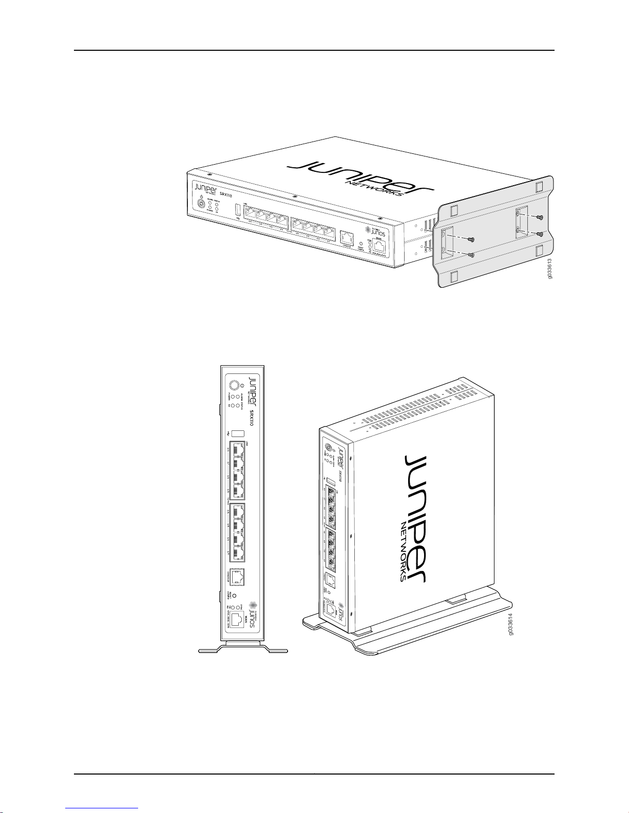
g033613
g033614
SRX110 Services Gateway Hardware Guide for H2 Model Numbers
Figure 17: SRX110 Services Gateway Desk Installation — Attaching the
Vertical Stand
3. Place the chassis vertically on the desk with the stand resting on the desk as shown
in Figure 18 on page 64.
Figure 18: SRX110 Services Gateway Desk Installation — Placing the
Services Gateway on a Desk
Related
Documentation
SRX110 Services Gateway Installation Safety Guidelines and Warnings on page 139•
• Required Tools and Parts for Installing and Maintaining the SRX110 Services Gateway
on page 48
Copyright © 2015, Juniper Networks, Inc.64
Page 85
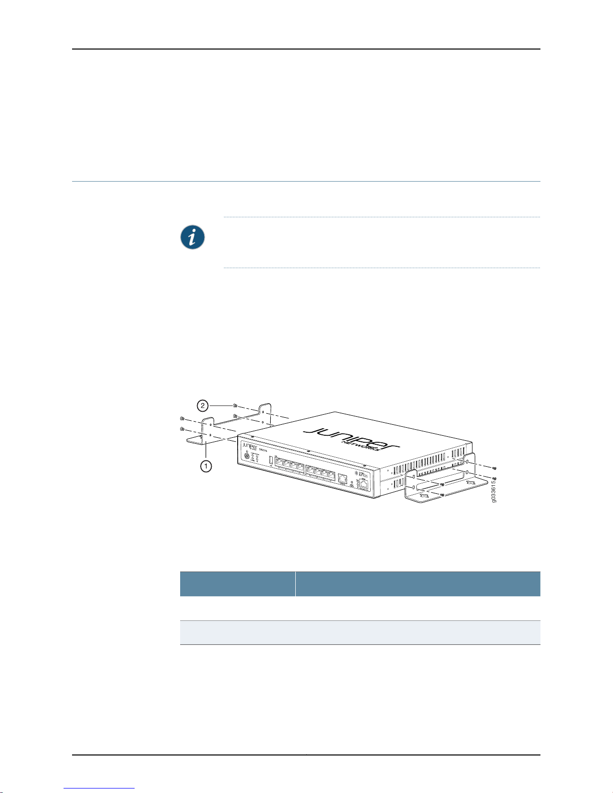
• Preparing the SRX110 Services Gateway for Rack-Mount, Desk-Mount, and Wall-Mount
g033615
Installation
• Installing the SRX110 Services Gateway on a Wall on page 65
Installing the SRX110 Services Gateway on a Wall
You can install the SRX110 Services Gateway on a wall.
NOTE: The wall-mounting kit is not shipped with the device and must be
ordered separately.
To install the device on a wall:
1. Place the device on a flat, level surface, with the Juniper Networks logo facing up. The
logo is embossed on the top cover. Ensure that the rubber feet are attached to the
bottom of the chassis.
Chapter 10: Installing the Services Gateway
2. Position a mounting bracket on each side of the chassis as shown in
Figure 19 on page 65.
Figure 19: SRX110 Services Gateway Wall Installation — Attaching the
Mounting Brackets
Table 35 on page 65 lists the parts to use to install the SRX110 Services Gateway on
a wall. The numbers in Figure 19 on page 65 correspond to the numbers in
Table 35 on page 65.
Table 35: SRX110 Services Gateway Wall Installation Parts
PartNumber
Mounting brackets1
Screws (mounting bracket)2
3. Use a Phillips (+) screwdriver,number 1,to install thescrews that secure themounting
brackets to the chassis.
4. If you are using wall anchors to support the chassis, install two pairs of anchors on
the wall.
65Copyright © 2015, Juniper Networks, Inc.
Page 86
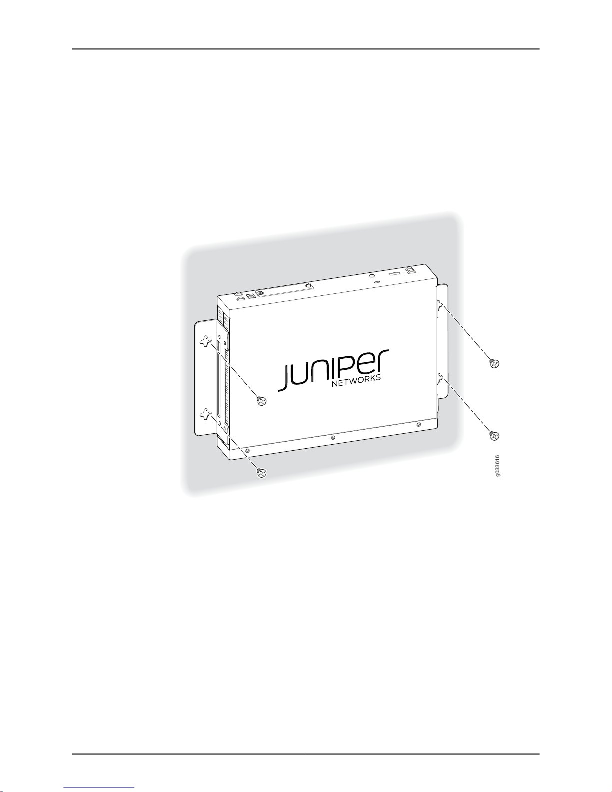
g033616
SRX110 Services Gateway Hardware Guide for H2 Model Numbers
5. Have one person grasp the sides of the device, lift it, and position it on the wall.
6. Have a second person install two pairs of mounting screws through the bracket holes
on either side of the device to secure it to the wall.
7. Verify that the mounting screws on one side are aligned with the mounting screws on
the opposite side and that the device is level (Figure 20 on page 66).
Figure 20: SRX110 Services Gateway Wall Installation — Attaching the
Mounting Brackets
Related
Documentation
General Site Guidelines for Installing the SRX110 Services Gateway on page 30•
• Required Tools and Parts for Installing and Maintaining the SRX110 Services Gateway
on page 48
• Preparing the SRX110 Services Gateway for Rack-Mount, Desk-Mount, and Wall-Mount
Installation
• Adjusting the Power Supply Adapter Tray for the SRX110 Services Gateway for
Rack-Mount Installation on page 62
• Installing the SRX110 Services Gateway in a Rack on page 59
• Installing the SRX110 Services Gateway on a Desk on page 63
Copyright © 2015, Juniper Networks, Inc.66
Page 87
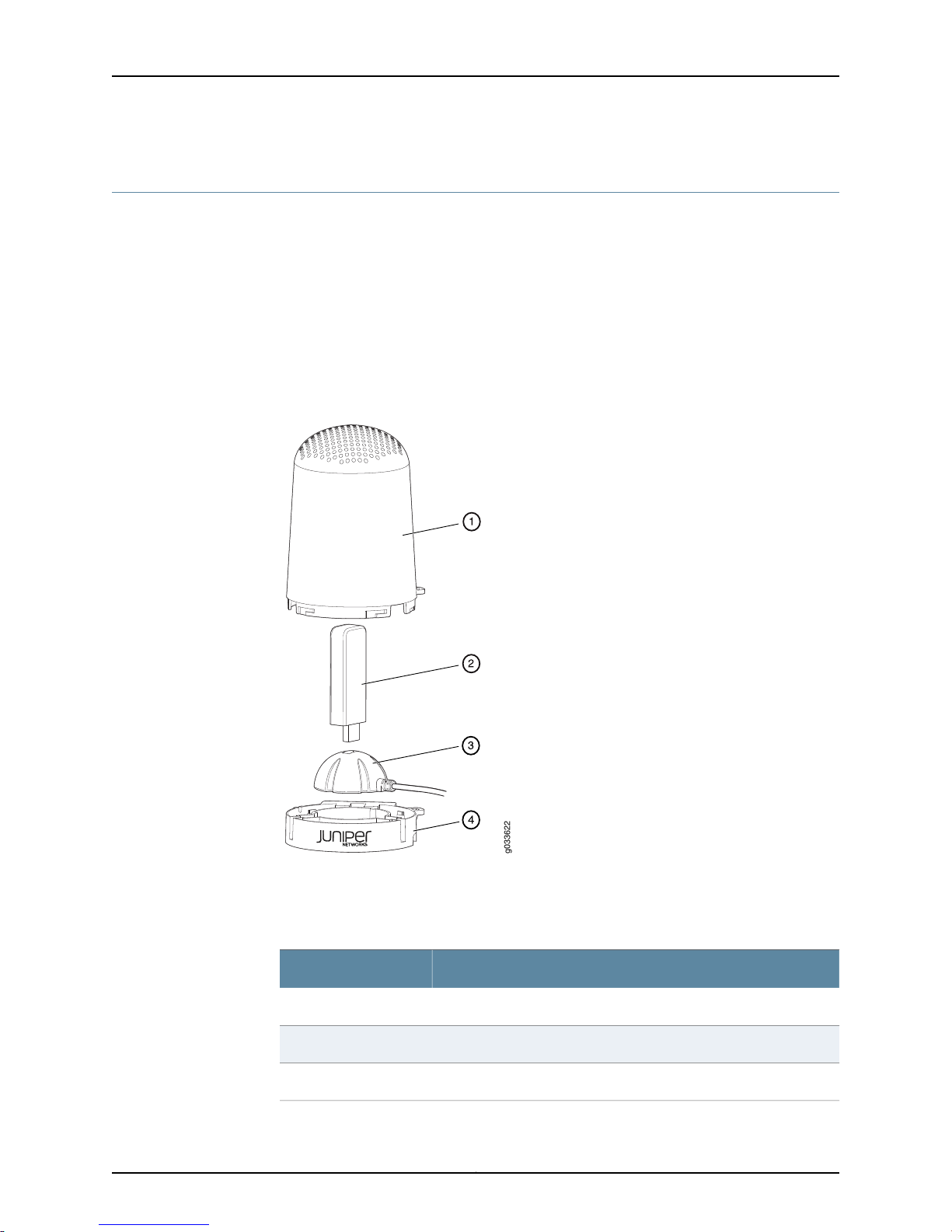
g033622
Chapter 10: Installing the Services Gateway
Installing a 3G USB Modem in the SRX110 Services Gateway USB Port
This topic includes the following sections:
•
Connecting the 3G USB Modemon theUSB ModemExtension Cable-Mount onpage 67
•
Installing a3G USB Modemon theRear Side of the SRX110 Services Gatewayon page 68
Connecting the 3G USB Modem on the USB Modem Extension Cable-Mount
The 3G USB modem is secured with a USB protection cover as shown in
Figure 21 on page 67.
Figure 21: 3G USB Modem with USB Protection Cover
Table 36 on page 67 lists the components of the 3G USB modem with USB protection
cover.
Table 36: 3G USB Modem with USB Protection Cover Components
ComponentNumber
USB mount top cover1
USB modem2
USB mount (magnetic/non-magnetic)3
67Copyright © 2015, Juniper Networks, Inc.
Page 88
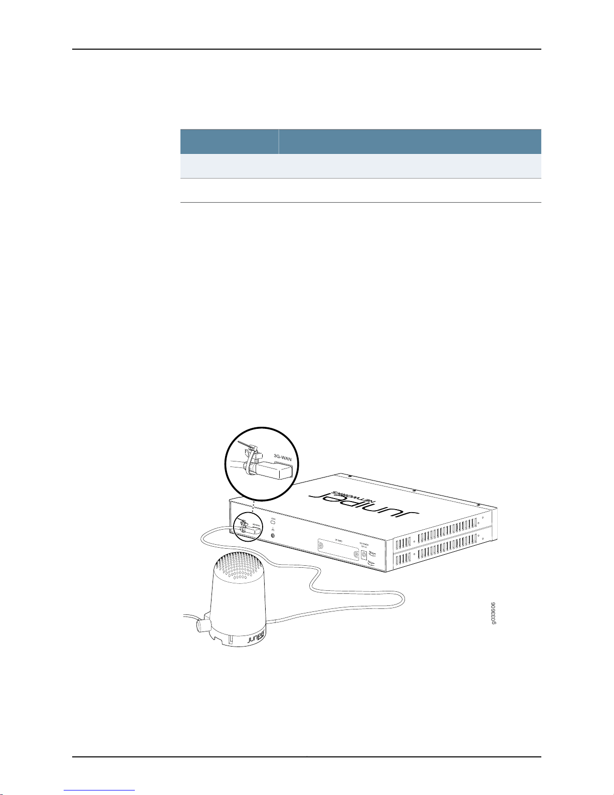
g033606
SRX110 Services Gateway Hardware Guide for H2 Model Numbers
Table 36: 3G USB Modem with USB Protection Cover
Components (continued)
ComponentNumber
USB mount base4
Lock5
To connect the 3G USB modem on the USB modem extension cable-mount:
1. Place the USB mount on the USB mount base.
2. Insert a 3G USB modem in the USB mount slot.
3. Close the USB mount top cover on the USB mount.
4. Lock the USB modem protection cover.
Installing a 3G USB Modem on the Rear Side of the SRX110 Services Gateway
To install the 3G USB modem on the rear side of the SRX110 Services Gateway:
1. Before you begin, ensure that the device is powered off.
2. On the rear sideof thedevice, insert the USB modemextension cable into the3G-WAN
USB port until the cable is engaged (see Figure 22 on page 68).
Figure 22: Connecting the 3G USB modem to the SRX110 Services Gateway
Copyright © 2015, Juniper Networks, Inc.68
Page 89
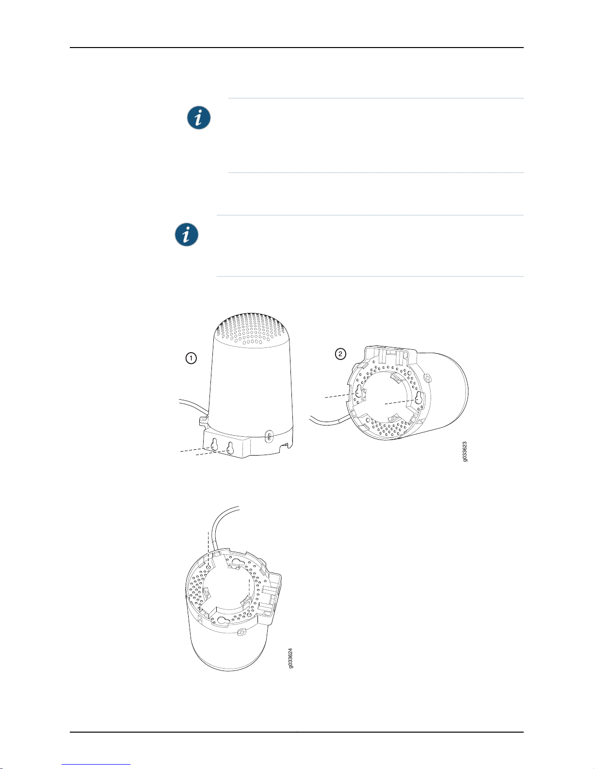
g033623
g033624
Chapter 10: Installing the Services Gateway
NOTE:
•
The 3G USB modem is not hot-swappable.
•
Ensure that the base of the 3G USB extension of the cable mount is 18
inches away from the device.
3. Power on the device. The 3G LED on the front panel of the device indicates the status
of the 3G USB modem interface.
NOTE: You can wall-mount the modem using keyholes as shown in
Figure 23 on page 69 or ceiling mount the USB protection cover using screw
holes as shown in Figure 24 on page 69.
Figure 23: 3G USB Modem Wall Installation—Attachingthe USB Protection
Cover
Figure 24: 3G USB Modem Ceiling Installation—Attaching the USB
Protection Cover
69Copyright © 2015, Juniper Networks, Inc.
Page 90

SRX110 Services Gateway Hardware Guide for H2 Model Numbers
Related
Documentation
• SRX110 Services Gateway 3G USB Modem Overview on page 10
• SRX110 Services Gateway 3G-WAN USB Port Physical Specifications on page 32
• Configuring the 3G USB Modem on the SRX110 Services Gateway on page 102
Copyright © 2015, Juniper Networks, Inc.70
Page 91
CHAPTER 11
Grounding the SRX110 Services Gateway
•
SRX110 Services Gateway Grounding Specifications on page 71
•
Grounding the SRX110 Services Gateway on page 72
SRX110 Services Gateway Grounding Specifications
To meet safety and electromagnetic interference (EMI) requirements and to ensure
proper operation, the services gateway must be adequately grounded before power is
connected. A grounding point available on the rear of the services gateway chassis is
used to connect the device to earth ground.
WARNING: Before device installation begins, a licensed electrician must
attach a cable lug to the grounding and power cables that you use. A cable
with an incorrectly attached lug can damage the device (for example, by
causing a short circuit).
Related
Documentation
To ground the device before connecting power, you connect the grounding cable to earth
ground and then attach the lug on the cable to the chassis grounding point with the
screw.
Table 37 on page 71 lists the specifications for the grounding cable used with the device.
Table 37: Grounding Cable Specifications for the Services Gateway
SpecificationGrounding Requirement
14 AWG single-strand wire cableGrounding cable
Up to 4 AAmperage of grounding cable
Grounding lug
SRX110 Services Gateway Site Electrical Wiring Guidelines on page 37•
• SRX110 Services Gateway Power Specifications and Requirements on page 39
• Interface Cable and Wire Specifications for the SRX110 Services Gateway on page 41
Ring-type, vinyl-insulated TV14-6R lug or
equivalent
71Copyright © 2015, Juniper Networks, Inc.
Page 92
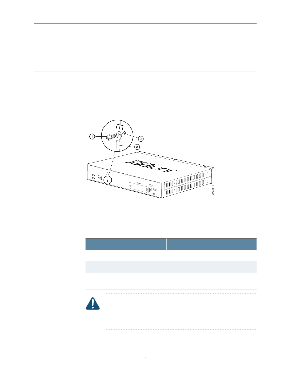
g033617
SRX110 Services Gateway Hardware Guide for H2 Model Numbers
• Grounding the SRX110 Services Gateway on page 72
Grounding the SRX110 Services Gateway
To meet safety and electromagnetic interference (EMI) requirements and to ensure
proper operation, you must adequately ground the SRX110 Services Gateway before
connecting power.
Figure 25 on page 72 illustrates connecting a grounding cable to the services gateway.
Figure 25: Grounding the SRX110 Services Gateway
To ground the device, connect a grounding cable to earth ground and then attach it to
the chassis grounding points, using one M3 screw.
Table 38 on page 72 lists the specifications of the grounding cable used with the device.
Table 38: Grounding Cable Specifications for the Services Gateway
SpecificationGrounding Requirement
14 AWG single-strand wire cableGrounding cable
Up to 4 AAmperage of grounding cable
Grounding lug
CAUTION: Before device installation begins, a licensed electrician must
attach a cable lug to the grounding and power cables that you use. A cable
with an incorrectly attached lug can damage the device (for example, by
causing a short circuit).
Ring-type, vinyl-insulated TV14-6R lug or
equivalent
Copyright © 2015, Juniper Networks, Inc.72
Page 93

Chapter 11: Grounding the SRX110 Services Gateway
To ground the device:
1. Connect the grounding cable to a proper earth ground.
2. Verify that a licensed electrician has attached the cable lug to the grounding cable.
3. Place thegrounding cable lug overthe groundingpoint onthe upper rear ofthe chassis.
4. Secure the grounding cable lug to the grounding point with the screw. Apply between
6 in.-lb (0.67 Nm) and 8 in.-lb (0.9 Nm) of torque to the screws.
5. Dress the grounding cable, and verify that it does not touch or block access to the
services gateway components and that it does not cause a tripping hazard.
NOTE: Thedevice should be permanently connectedto ground during normal
operation.
Related
Documentation
• Connecting the SRX110 Services Gateway to the Power Supply on page 79
• Connecting and Organizing the SRX110 Services Gateway Interface Cables on page 75
• SRX110 Services Gateway Grounding Specifications on page 71
• Powering On the SRX110 Services Gateway on page 80
• Powering Off the SRX110 Services Gateway on page 81
• SRX110 Services Gateway General Safety Guidelines and Warnings on page 131
73Copyright © 2015, Juniper Networks, Inc.
Page 94

SRX110 Services Gateway Hardware Guide for H2 Model Numbers
Copyright © 2015, Juniper Networks, Inc.74
Page 95

CHAPTER 12
Connecting the SRX110 Services Gateway
to External Devices
•
Connecting and Organizing the SRX110 Services Gateway Interface Cables on page 75
•
Connecting the Modem at the SRX110 Services Gateway End on page 76
•
Connecting the Modem to the Console Port on the SRX110 Services Gateway onpage 77
•
Connecting to the CLI at the User End for the SRX110 Services Gateway on page 77
Connecting and Organizing the SRX110 Services Gateway Interface Cables
You can connect the interfaces installed in the services gateway to various network
media. Each type of interface on the services gateway uses a particular medium to
transmit data. You must configure each network interface before it can operate on the
device.
To connect and organize an interface cable for the device:
Related
Documentation
1. Have ready a length of the type of cable used by the interface.
2. Insert the cable connector into the cable connector port on the interface faceplate.
3. Arrange network cables as follows to prevent them from dislodging or developing
stress points:
•
Secure cables so that they are not supporting their own weight as they hang to the
floor.
•
Place excess cable out of the way in neatly coiled loops.
•
Use fasteners to maintain the shape of cable loops.
Connecting the SRX110 Services Gateway to the Power Supply on page 79•
• Grounding the SRX110 Services Gateway on page 72
• Interface Cable and Wire Specifications for the SRX110 Services Gateway on page 41
• General Site Guidelines for Installing the SRX110 Services Gateway on page 30
75Copyright © 2015, Juniper Networks, Inc.
Page 96
SRX110 Services Gateway Hardware Guide for H2 Model Numbers
Connecting the Modem at the SRX110 Services Gateway End
NOTE: These instructions use Hayes-compatible modem commands to
configure the modem. If your modem is not Hayes-compatible, refer to the
documentationfor your modem and enter the equivalentmodem commands.
To configure the modem on the services gateway end:
1. Connect the modem to a PC or laptop computer.
2. Power on the modem.
3. From the PC or laptop computer, start your asynchronous terminal emulation
application (such as Microsoft Windows HyperTerminal), and select the COM port to
which the modem is connected (for example, COM1).
4. Configure the port settings as shown in Table 39 on page 76.
Table 39: Port Settings for Configuring the Modem on the Services
Gateway End
ValuePort Setting
9600Bits per second
8Data bits
NoneParity
1Stop bits
NoneFlow control
5. In the HyperTerminal window, enter AT.
For more information on the AT commands, see the following topics:
•
Initial Configuration for Security Devices
•
Monitoring and Troubleshooting for Security Devices
An OKresponse verifies thatthe modem can communicate successfully with the COM
port on the PC or laptop.
6. Configure the modem to answer a call on the first ring by entering ATS0=1.
7. Configure the modem to accept modem control DTR signals by entering AT&D1.
8. Disable flow control by entering AT&K0.
9. Save modem settings by entering AT&W.
Copyright © 2015, Juniper Networks, Inc.76
Page 97

Chapter 12: Connecting the SRX110 Services Gateway to External Devices
Related
Documentation
Connecting the Modem to the Console Port on the SRX110 Services Gateway onpage 77•
• Connecting to the CLI at the User End for the SRX110 Services Gateway on page 77
• SRX110 Services Gateway Software Configuration Overview on page 83
Connecting the Modem to the Console Port on the SRX110 Services Gateway
To connect the dial-up modem to the console port on the services gateway:
1. Turn off power to the services gateway.
2. Turn off power to the modem.
3. Plug one end of the Ethernet cable supplied with your services gateway into the
console port on the services gateway.
4. Plug the other end of the CAT-5e cable (Ethernet cable) into the RJ-45 to DB-9 serial
port adapter supplied with your services gateway.
5. Connect the serial port adapter to a separately purchased DB-9 female to DB-25
male adapter or other adapter appropriate for your modem.
6. Plug the modem adapter into the DB-25 connector on the modem.
7. Connect the modem to your telephone network.
8. Turn on the power to the modem.
9. Power on the services gateway by pressing the Power button on the front panel. Verify
that the Power LED on the front panel turns green.
NOTE: Most modems have an RS-232 DB-25 connector. You must
separately purchase an adapter to connect your modem to the RJ-45 to
DB-9 adapter and the Ethernet cable supplied with the services gateway.
Related
Documentation
Connecting the Modem at the SRX110 Services Gateway End on page 76•
• Connecting to the CLI at the User End for the SRX110 Services Gateway on page 77
• SRX110 Services Gateway Software Configuration Overview on page 83
Connecting to the CLI at the User End for the SRX110 Services Gateway
To remotely connect to the CLI through a dial-up modem connected to the console port
on the services gateway:
1. Connect a modem at your remote location to a management device such as a PC or
laptop computer.
2. Start your asynchronous terminal emulation application (such as Microsoft Windows
HyperTerminal) on the PC or laptop computer.
77Copyright © 2015, Juniper Networks, Inc.
Page 98
SRX110 Services Gateway Hardware Guide for H2 Model Numbers
3. Select the COM port to which the modem is connected (for example, COM1).
4. Configure the port settings shown in Table 40 on page 78.
Table 40: Port Settings for Connecting to the CLI at User End
5. In the HyperTerminal window, enter AT.
ValuePort Setting
9600Bits per second
8Data bits
NoneParity
1Stop bits
NoneFlow control
Related
Documentation
For more information on the AT commands, see the following topics:
•
Initial Configuration for Security Devices
•
Monitoring and Troubleshooting for Security Devices
An OKresponse verifies thatthe modem can communicate successfully with the COM
port on the PC or laptop.
6. Dial the modem that is connected to the console port on the services gateway by
entering ATDT remote-modem-number. For example, if the number of the modem
connectedto the consoleport onthe services gateway is0013033033030, enter ATDT
0013033033030.
The services gateway login prompt appears.
7. Log in as the user root. No password is required at initial connection, but you must
assign a root password before committing any configuration settings.
• Connecting the Modem at the SRX110 Services Gateway End on page 76
• Connecting theModem tothe Console Port on the SRX110 Services Gateway onpage 77
• SRX110 Services Gateway Software Configuration Overview on page 83
Copyright © 2015, Juniper Networks, Inc.78
Page 99
CHAPTER 13
Providing Power to the SRX110 Services
Gateway
•
Connecting the SRX110 Services Gateway to the Power Supply on page 79
•
Powering On the SRX110 Services Gateway on page 80
•
Powering Off the SRX110 Services Gateway on page 81
Connecting the SRX110 Services Gateway to the Power Supply
To connect the device to the power supply:
CAUTION: Before connecting the device to the power supply, attach an ESD
strap to an ESD point and place the other end of the strap around your bare
wrist.
NOTE: If you are installing your services gateway on a desk, ensure that your
device is adequately grounded using the grounding point on the back panel
of the chassis.
1. Plug the DC connector end of the power cable into the power connector on the back
of the device (see Figure 26 on page 80).
2. Plug the AC adapter end of the power cable into an AC power outlet.
79Copyright © 2015, Juniper Networks, Inc.
Page 100
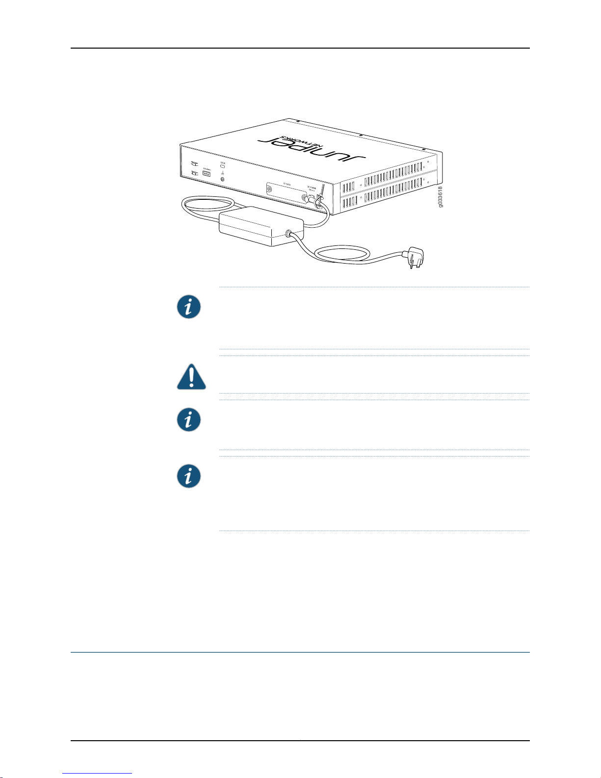
g033618
SRX110 Services Gateway Hardware Guide for H2 Model Numbers
Figure 26: Connecting the SRX110 Services Gateway to the Power Supply
NOTE: The device must be connected to earth ground during normal
operation. The protective earthing terminal on the rear of the chassis is
provided to connect the device to ground.
CAUTION: Werecommend using a surge protector for the power connection.
NOTE: Use the cable tie holder to secure the power cord on the power supply
point.
NOTE: We strongly recommend that you use only the 3-prong power cord
supplied with your services gateway. If you are using a 2-prong power cord,
then ensure that your device is adequately grounded using the grounding
point available on the back panel of the chassis.
Related
Documentation
Required Tools and Parts for Installing and Maintaining the SRX110 Services Gateway
•
on page 48
• Grounding the SRX110 Services Gateway on page 72
• Connecting and Organizing the SRX110 Services Gateway Interface Cables on page 75
• SRX110 Services Gateway General Safety Guidelines and Warnings on page 131
Powering On the SRX110 Services Gateway
To power on the services gateway:
1. Ensure that you have connected the power supply to the device.
Copyright © 2015, Juniper Networks, Inc.80
 Loading...