

Page 1

SRX100 Services Gateway Hardware Guide
Published
2020-11-10
for B and H Model Numbers
Page 2

Juniper Networks, Inc.
1133 Innovation Way
Sunnyvale, California 94089
USA
408-745-2000
www.juniper.net
Juniper Networks, the Juniper Networks logo, Juniper, and Junos are registered trademarks of Juniper Networks, Inc. in
the United States and other countries. All other trademarks, service marks, registered marks, or registered service marks
are the property of their respective owners.
Juniper Networks assumes no responsibility for any inaccuracies in this document. Juniper Networks reserves the right
to change, modify, transfer, or otherwise revise this publication without notice.
SRX100 Services Gateway Hardware Guide for B and H Model Numbers
Copyright © 2020 Juniper Networks, Inc. All rights reserved.
The information in this document is current as of the date on the title page.
ii
YEAR 2000 NOTICE
Juniper Networks hardware and software products are Year 2000 compliant. Junos OS has no known time-related
limitations through the year 2038. However, the NTP application is known to have some difficulty in the year 2036.
END USER LICENSE AGREEMENT
The Juniper Networks product that is the subject of this technical documentation consists of (or is intended for use with)
Juniper Networks software. Use of such software is subject to the terms and conditions of the End User License Agreement
(“EULA”) posted at https://support.juniper.net/support/eula/. By downloading, installing or using such software, you
agree to the terms and conditions of that EULA.
Page 3

Table of Contents
1
About the Documentation | ix
Documentation and Release Notes | ix
Using the Examples in This Manual | ix
Merging a Full Example | x
Merging a Snippet | xi
Documentation Conventions | xi
Documentation Feedback | xiv
Requesting Technical Support | xiv
Self-Help Online Tools and Resources | xv
Creating a Service Request with JTAC | xv
iii
Overview
System Overview | 2
SRX100 Services Gateway Description | 2
About the SRX100 Services Gateway | 2
SRX100 Services Gateway Models | 3
Accessing the SRX100 Services Gateway | 3
SRX100 Services Gateway Features and Functions | 4
Hardware Component Overview | 6
SRX100 Services Gateway LEDs | 6
SRX100 Services Gateway Front Panel LEDs | 6
SRX100 Services Gateway Ethernet Port LEDs | 8
SRX100 Services Gateway Power Supply | 9
SRX100 Services Gateway Boot Devices and Dual-Root Partitioning Scheme | 10
Boot Devices | 10
Dual-Root Partitioning Scheme | 10
Page 4

Chassis Description | 12
2
3
SRX100 Services Gateway Front Panel and Back Panel Views | 12
SRX100 Services Gateway Front Panel | 12
SRX100 Services Gateway Back Panel | 13
SRX100 Services Gateway Built-In Interfaces | 14
Site Planning and Specifications
Planning and Preparing the Site | 18
Site Preparation Checklist for the SRX100 Services Gateway | 18
General Site Guidelines for Installing the SRX100 Services Gateway | 21
SRX100 Services Gateway Specifications | 21
SRX100 Services Gateway Cabinet Requirements | 23
SRX100 Services Gateway Rack Requirements | 24
Clearance Requirements for Airflow and Hardware Maintenance of the SRX100 Services
Gateway | 25
iv
Power Requirements and Specifications | 27
SRX100 Services Gateway Site Electrical Wiring Guidelines | 27
SRX100 Services Gateway Electrical and Power Requirements | 29
SRX100 Services Gateway Power Specifications and Requirements | 29
Cable Specifications and Pinouts | 31
Interface Cable and Wire Specifications for the SRX100 Services Gateway | 31
RJ-45 Connector Pinouts for the SRX100 Services Gateway Ethernet Port | 32
RJ-45 Connector Pinouts for the SRX100 Services Gateway Console Port | 32
Initial Installation and Configuration
Installation Overview | 35
Installation Overview for the SRX100 Services Gateway | 36
Required Tools and Parts for Installing and Maintaining the SRX100 Services Gateway | 37
SRX100 Services Gateway Autoinstallation Overview | 38
Unpacking the Services Gateway | 40
Unpacking the SRX100 Services Gateway | 40
Verifying Parts Received with the SRX100 Services Gateway | 41
Page 5

Installing the Mounting Hardware | 43
Preparing the SRX100 Services Gateway for Rack-Mount Installation | 43
Preparing the SRX100 Services Gateway for Desk-Mount Installation | 44
Preparing the SRX100 Services Gateway for Wall-Mount Installation | 45
Installing the Services Gateway | 46
Installing the SRX100 Services Gateway in a Rack | 46
Installing the SRX100 Services Gateway on a Desk | 48
Installing the SRX100 Services Gateway on a Wall | 49
Grounding the SRX100 Services Gateway | 52
Grounding the SRX100 Services Gateway | 52
Connecting the SRX100 Services Gateway to External Devices | 55
v
Connecting and Organizing Interface Cables to the SRX100 Services Gateway | 55
Connecting the Modem at the SRX100 Services Gateway End | 56
Connecting the Modem to the Console Port on the SRX100 Services Gateway | 57
Connecting to the CLI at the User End for the SRX100 Services Gateway | 58
Providing Power to the SRX100 Services Gateway | 60
Connecting the SRX100 Services Gateway to the Power Supply | 60
Powering On and Powering Off the SRX100 Services Gateway | 61
Powering On the SRX100 Services Gateway | 61
Powering Off the SRX100 Services Gateway | 62
Performing Initial Configuration | 65
SRX100 Services Gateway Software Configuration Overview | 65
Preparing the SRX100 Services Gateway for Configuration | 66
Understanding the Factory Default Configuration | 66
Understanding Built-In Ethernet Ports and Initial Configuration | 67
Mapping the Chassis Cluster Ports | 67
Understanding Management Access | 68
Connecting to the SRX100 Services Gateway Setup Wizard | 69
SRX100 Services Gateway Secure Web Access Overview | 70
Connecting an SRX100 Services Gateway to the CLI Locally | 71
Page 6

Connecting an SRX100 Services Gateway to the CLI Remotely | 74
4
5
Viewing Factory-Default Settings of the SRX100 Services Gateway | 74
Performing Initial Software Configuration on the SRX100 Services Gateway Using the CLI | 83
Performing Initial Software Configuration on the SRX100 Services Gateway Using the J-Web
Interface | 87
Establishing Basic Connectivity | 88
Configuring Basic System Properties | 89
Upgrading the SRX100 Services Gateway Low Memory Version to a High Memory Version | 92
Maintaining and Troubleshooting Components
Maintaining Components | 95
Maintaining the SRX100 Services Gateway Hardware Components | 95
Troubleshooting Components | 97
vi
Monitoring the SRX100 Services Gateway Chassis Using the CLI | 97
Monitoring the SRX100 Services Gateway Components Using LEDs | 100
Monitoring the SRX100 Services Gateway Using Chassis Alarm Conditions | 102
Monitoring the SRX100 Services Gateway Power System | 103
Using the Reset Config Button on the SRX100 Services Gateway | 104
Changing the Reset Config Button Behavior on the SRX100 Services Gateway | 106
Juniper Networks Technical Assistance Center | 107
Replacing Components
Contacting Customer Support and Returning Components | 109
Contacting Customer Support | 109
Return Procedure for the SRX100 Services Gateway | 110
Information You Might Need to Supply to Juniper Networks Technical Assistance Center | 111
Locating the SRX100 Services Gateway Component Serial Number and Agency Labels | 111
Packing the SRX100 Services Gateway and Components for Shipment | 113
Page 7

Safety and Regulatory Compliance Information
6
General Safety Guidelines and Warnings | 116
SRX100 Services Gateway Definition of Safety Warning Levels | 116
SRX100 Services Gateway General Safety Guidelines and Warnings | 119
General Safety Guidelines and Warnings | 119
Qualified Personnel Warning | 121
Restricted Access Area Warning | 122
Preventing Electrostatic Discharge Damage to the Services Gateway | 124
SRX100 Services Gateway Safety Requirements, Warnings, and Guidelines | 125
Fire Safety Requirements | 127
SRX100 Services Gateway Fire Safety Requirements | 127
Installation Safety Guidelines and Warnings | 129
vii
SRX100 Services Gateway Installation Safety Guidelines and Warnings | 129
Laser and LED Safety Guidelines and Warnings | 136
SRX100 Services Gateway Laser and LED Safety Guidelines and Warnings | 136
Laser and LED Safety Guidelines and Warnings | 136
General Laser Safety Guidelines | 136
Class 1 Laser Product Warning | 137
Class 1 LED Product Warning | 137
Laser Beam Warning | 138
Radiation from Open Port Apertures Warning | 139
Maintenance and Operational Safety Guidelines and Warnings | 141
SRX100 Services Gateway Maintenance and Operational Safety Guidelines and Warnings | 141
Safety Guidelines and Warnings | 142
Battery Handling Warning | 142
Jewelry Removal Warning | 143
Lightning Activity Warning | 145
Operating Temperature Warning | 146
Product Disposal Warning | 148
Page 8

Electrical Safety Guidelines and Warnings | 150
SRX100 Services Gateway Electrical Safety Guidelines and Warnings | 150
Electrical Safety Guidelines and Warnings | 150
In Case of Electrical Accident | 150
General Electrical Safety Guidelines and Warnings | 150
Agency Approvals and Regulatory Compliance Information | 152
SRX100 Services Gateway Agency Approvals | 152
SRX100 Services Gateway Compliance Statements for EMC Requirements | 153
Canada | 154
European Community | 154
Japan | 154
Korean | 154
United States | 154
viii
SRX100 Services Gateway Compliance Statements for Environmental Requirements | 155
Page 9
About the Documentation
IN THIS SECTION
Documentation and Release Notes | ix
Using the Examples in This Manual | ix
Documentation Conventions | xi
Documentation Feedback | xiv
Requesting Technical Support | xiv
Use this guide to install hardware and perform initial software configuration, routine maintenance, and
troubleshooting for the SRX100 Services Gateway (B and H model numbers). After completing the
installation and basic configuration procedures covered in this guide, refer to the Junos OS documentation
for information about further software configuration.
ix
Documentation and Release Notes
To obtain the most current version of all Juniper Networks®technical documentation, see the product
documentation page on the Juniper Networks website at https://www.juniper.net/documentation/.
If the information in the latest release notes differs from the information in the documentation, follow the
product Release Notes.
Juniper Networks Books publishes books by Juniper Networks engineers and subject matter experts.
These books go beyond the technical documentation to explore the nuances of network architecture,
deployment, and administration. The current list can be viewed at https://www.juniper.net/books.
Using the Examples in This Manual
If you want to use the examples in this manual, you can use the load merge or the load merge relative
command. These commands cause the software to merge the incoming configuration into the current
candidate configuration. The example does not become active until you commit the candidate configuration.
Page 10

If the example configuration contains the top level of the hierarchy (or multiple hierarchies), the example
is a full example. In this case, use the load merge command.
If the example configuration does not start at the top level of the hierarchy, the example is a snippet. In
this case, use the load merge relative command. These procedures are described in the following sections.
Merging a Full Example
To merge a full example, follow these steps:
1. From the HTML or PDF version of the manual, copy a configuration example into a text file, save the
file with a name, and copy the file to a directory on your routing platform.
For example, copy the following configuration to a file and name the file ex-script.conf. Copy the
ex-script.conf file to the /var/tmp directory on your routing platform.
system {
scripts {
commit {
file ex-script.xsl;
}
}
}
interfaces {
fxp0 {
disable;
unit 0 {
family inet {
address 10.0.0.1/24;
}
}
}
}
x
2. Merge the contents of the file into your routing platform configuration by issuing the load merge
configuration mode command:
[edit]
user@host# load merge /var/tmp/ex-script.conf
load complete
Page 11

Merging a Snippet
To merge a snippet, follow these steps:
1. From the HTML or PDF version of the manual, copy a configuration snippet into a text file, save the
file with a name, and copy the file to a directory on your routing platform.
For example, copy the following snippet to a file and name the file ex-script-snippet.conf. Copy the
ex-script-snippet.conf file to the /var/tmp directory on your routing platform.
commit {
file ex-script-snippet.xsl; }
2. Move to the hierarchy level that is relevant for this snippet by issuing the following configuration mode
command:
[edit]
user@host# edit system scripts
[edit system scripts]
xi
3. Merge the contents of the file into your routing platform configuration by issuing the load merge
relative configuration mode command:
[edit system scripts]
user@host# load merge relative /var/tmp/ex-script-snippet.conf
load complete
For more information about the load command, see CLI Explorer.
Documentation Conventions
Table 1 on page xii defines notice icons used in this guide.
Page 12
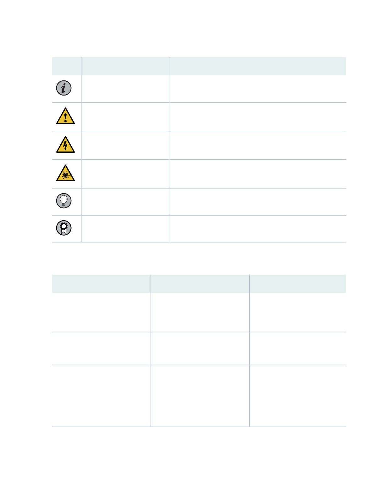
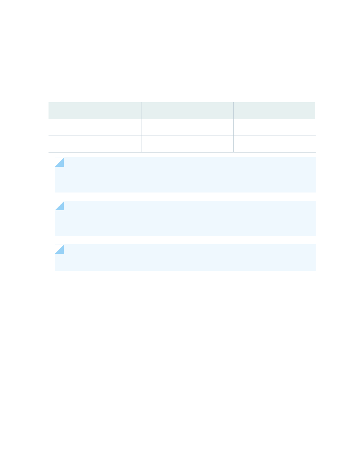
Table 1: Notice Icons
xii
DescriptionMeaningIcon
Indicates important features or instructions.Informational note
Caution
Indicates a situation that might result in loss of data or hardware
damage.
Alerts you to the risk of personal injury or death.Warning
Alerts you to the risk of personal injury from a laser.Laser warning
Indicates helpful information.Tip
Alerts you to a recommended use or implementation.Best practice
Table 2 on page xii defines the text and syntax conventions used in this guide.
Table 2: Text and Syntax Conventions
ExamplesDescriptionConvention
Fixed-width text like this
Italic text like this
Represents text that you type.Bold text like this
Represents output that appears on
the terminal screen.
Introduces or emphasizes important
•
new terms.
Identifies guide names.
•
Identifies RFC and Internet draft
•
titles.
To enter configuration mode, type
the configure command:
user@host> configure
user@host> show chassis alarms
No alarms currently active
A policy term is a named structure
•
that defines match conditions and
actions.
Junos OS CLI User Guide
•
RFC 1997, BGP Communities
•
Attribute
Page 13

Table 2: Text and Syntax Conventions (continued)
xiii
ExamplesDescriptionConvention
Italic text like this
Text like this
< > (angle brackets)
| (pipe symbol)
Represents variables (options for
which you substitute a value) in
commands or configuration
statements.
Represents names of configuration
statements, commands, files, and
directories; configuration hierarchy
levels; or labels on routing platform
components.
variables.
Indicates a choice between the
mutually exclusive keywords or
variables on either side of the symbol.
The set of choices is often enclosed
in parentheses for clarity.
Configure the machine’s domain
name:
[edit]
root@# set system domain-name
domain-name
To configure a stub area, include
•
the stub statement at the [edit
protocols ospf area area-id]
hierarchy level.
The console port is labeled
•
CONSOLE.
stub <default-metric metric>;Encloses optional keywords or
broadcast | multicast
(string1 | string2 | string3)
# (pound sign)
[ ] (square brackets)
Indention and braces ( { } )
; (semicolon)
GUI Conventions
Indicates a comment specified on the
same line as the configuration
statement to which it applies.
Encloses a variable for which you can
substitute one or more values.
Identifies a level in the configuration
hierarchy.
Identifies a leaf statement at a
configuration hierarchy level.
rsvp { # Required for dynamic MPLS
only
community name members [
community-ids ]
[edit]
routing-options {
static {
route default {
nexthop address;
retain;
}
}
}
Page 14
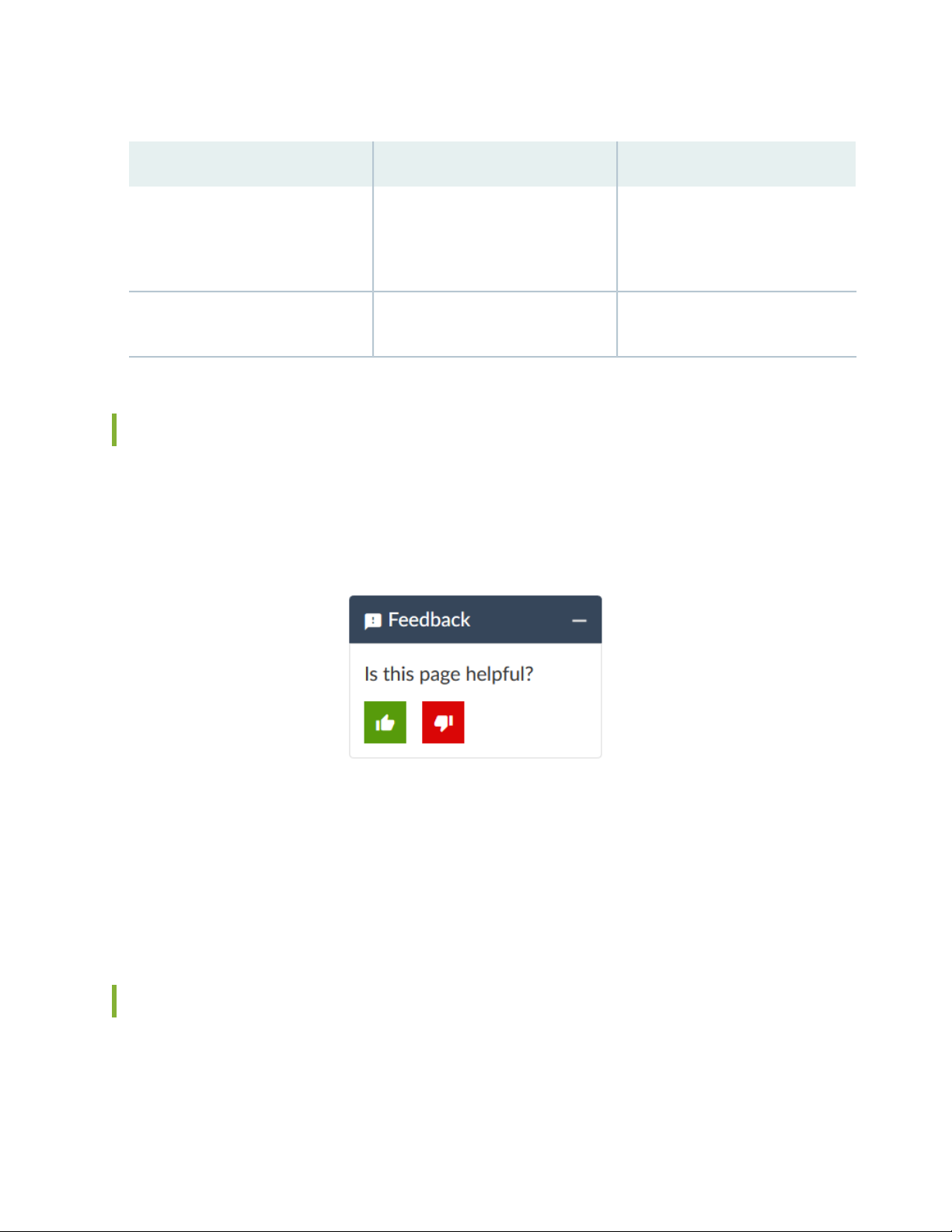
Table 2: Text and Syntax Conventions (continued)
xiv
ExamplesDescriptionConvention
Bold text like this
> (bold right angle bracket)
Represents graphical user interface
(GUI) items you click or select.
Separates levels in a hierarchy of
menu selections.
In the Logical Interfaces box, select
•
All Interfaces.
To cancel the configuration, click
•
Cancel.
In the configuration editor hierarchy,
select Protocols>Ospf.
Documentation Feedback
We encourage you to provide feedback so that we can improve our documentation. You can use either
of the following methods:
Online feedback system—Click TechLibrary Feedback, on the lower right of any page on the Juniper
•
Networks TechLibrary site, and do one of the following:
Click the thumbs-up icon if the information on the page was helpful to you.
•
Click the thumbs-down icon if the information on the page was not helpful to you or if you have
•
suggestions for improvement, and use the pop-up form to provide feedback.
E-mail—Send your comments to techpubs-comments@juniper.net. Include the document or topic name,
•
URL or page number, and software version (if applicable).
Requesting Technical Support
Technical product support is available through the Juniper Networks Technical Assistance Center (JTAC).
If you are a customer with an active Juniper Care or Partner Support Services support contract, or are
Page 15

covered under warranty, and need post-sales technical support, you can access our tools and resources
online or open a case with JTAC.
JTAC policies—For a complete understanding of our JTAC procedures and policies, review the JTAC User
•
Guide located at https://www.juniper.net/us/en/local/pdf/resource-guides/7100059-en.pdf.
Product warranties—For product warranty information, visit https://www.juniper.net/support/warranty/.
•
JTAC hours of operation—The JTAC centers have resources available 24 hours a day, 7 days a week,
•
365 days a year.
Self-Help Online Tools and Resources
For quick and easy problem resolution, Juniper Networks has designed an online self-service portal called
the Customer Support Center (CSC) that provides you with the following features:
Find CSC offerings: https://www.juniper.net/customers/support/
•
Search for known bugs: https://prsearch.juniper.net/
•
xv
Find product documentation: https://www.juniper.net/documentation/
•
Find solutions and answer questions using our Knowledge Base: https://kb.juniper.net/
•
Download the latest versions of software and review release notes:
•
https://www.juniper.net/customers/csc/software/
Search technical bulletins for relevant hardware and software notifications:
•
https://kb.juniper.net/InfoCenter/
Join and participate in the Juniper Networks Community Forum:
•
https://www.juniper.net/company/communities/
Create a service request online: https://myjuniper.juniper.net
•
To verify service entitlement by product serial number, use our Serial Number Entitlement (SNE) Tool:
https://entitlementsearch.juniper.net/entitlementsearch/
Creating a Service Request with JTAC
You can create a service request with JTAC on the Web or by telephone.
Visit https://myjuniper.juniper.net.
•
Call 1-888-314-JTAC (1-888-314-5822 toll-free in the USA, Canada, and Mexico).
•
For international or direct-dial options in countries without toll-free numbers, see
https://support.juniper.net/support/requesting-support/.
Page 16

1
PART
Overview
System Overview | 2
Hardware Component Overview | 6
Chassis Description | 12
Page 17
CHAPTER 1
System Overview
IN THIS CHAPTER
SRX100 Services Gateway Description | 2
SRX100 Services Gateway Features and Functions | 4
SRX100 Services Gateway Description
2
IN THIS SECTION
About the SRX100 Services Gateway | 2
SRX100 Services Gateway Models | 3
Accessing the SRX100 Services Gateway | 3
This topic includes the following sections:
About the SRX100 Services Gateway
The Juniper Networks SRX100 Services Gateway offers features that provide complete functionality and
flexibility for delivering secure Internet and intranet access. The services gateway offers stable, reliable,
and efficient IP routing in addition to switching support and LAN connectivity. The device provides IP
Security (IPsec), virtual private network (VPN), and firewall services for small and medium-sized companies
and enterprise branch and remote offices. The SRX100 Services Gateway can be connected directly to
traditional private networks such as leased lines, Frame Relay, or Multi Protocol Label Switching (MPLS)
or to the public Internet.
The SRX100 Services Gateway runs the Junos operating system (Junos OS).
Page 18
SRX100 Services Gateway Models
The following are the two models of the SRX100 Services Gateway available with 1 GB memory. For
information on the models with 2 GB memory, see SRX100 Services Gateway Hardware Guide for H2
Model Numbers.
Table 3: SRX100 Services Gateway Models
Model NumberDevice TypeProduct Name
SRX100BLow MemorySRX100 Services Gateway
SRX100HHigh MemorySRX100 Services Gateway
NOTE: You can upgrade from an SRX100 Services Gateway Low Memory version to a High
Memory version through a license key. You need not order a separate High Memory device.
3
NOTE: SRX100H model provides additional security features such as Unified Threat Management
(UTM), which consists of IPS antispam, antivirus, and Web filtering.
NOTE: The SRX100 Services Gateway High Memory model ships with a license key.
All SRX100 Services Gateways run the Junos OS.
Accessing the SRX100 Services Gateway
Two user interfaces are available for monitoring, configuring, troubleshooting, and managing the SRX100
Services Gateway:
J-Web interface: Web-based graphical interface that allows you to operate a services gateway without
•
commands. The J-Web interface provides access to all Junos OS functionality and features.
Junos OS command-line interface (CLI): Juniper Networks command shell that runs on top of a UNIX-based
•
operating system kernel. The CLI is a straightforward command interface. On a single line, you type
commands that are executed when you press the Enter key. The CLI provides command Help and
command completion.
Page 19

RELATED DOCUMENTATION
SRX100 Services Gateway Specifications | 21
SRX100 Services Gateway Features and Functions | 4
Upgrading the SRX100 Services Gateway Low Memory Version to a High Memory Version | 92
SRX100 Services Gateway Features and Functions
The SRX100 Services Gateway is a security optimized, fixed processing system that provides the following
features for the Low Memory and High Memory models listed in Table 4 on page 4. For information on
the models with 2 GB memory, see SRX100 Services Gateway Hardware Guide for H2 Model Numbers.
Table 4: SRX100 Services Gateway Hardware Features
4
SRX100 Services Gateway Low
MemoryFeatures
DDR Memory
Memory through a license key)
SRX100 Services Gateway High
Memory
1 GB512 MB (software upgradable to High
30 watts30 wattsPower supply adapter
100 to 240 VAC100 to 240 VACAC input voltage
88Fast Ethernet ports
11Console port
11USB port
44LEDs
1 GB1 GBNAND flash
For more details on Junos OS features and licenses for the SRX100 Services Gateway, see the Junos OS
Administration Guide for Security Devices.
For more information on upgrading an SRX100 Services Gateway Low Memory to High Memory, see
“Upgrading the SRX100 Services Gateway Low Memory Version to a High Memory Version” on page 92.
RELATED DOCUMENTATION
Page 20

SRX100 Services Gateway Description | 2
SRX100 Services Gateway Specifications | 21
Upgrading the SRX100 Services Gateway Low Memory Version to a High Memory Version | 92
5
Page 21
CHAPTER 2
Hardware Component Overview
IN THIS CHAPTER
SRX100 Services Gateway LEDs | 6
SRX100 Services Gateway Power Supply | 9
SRX100 Services Gateway Boot Devices and Dual-Root Partitioning Scheme | 10
SRX100 Services Gateway LEDs
6
IN THIS SECTION
SRX100 Services Gateway Front Panel LEDs | 6
SRX100 Services Gateway Ethernet Port LEDs | 8
This topic includes the following sections:
SRX100 Services Gateway Front Panel LEDs
Figure 1 on page 7 illustrates the front panel LEDs of the SRX100 Services Gateway.
NOTE: The numbers in Figure 1 on page 7 correspond to the numbers in Table 5 on page 7.
Page 22

Figure 1: SRX100 Services Gateway Front Panel LEDs
Table 5 on page 7 lists the LED indicators on the SRX100 Services Gateway front panel.
Table 5: SRX100 Services Gateway Front Panel LEDs
UsageDescriptionComponentNumber
7
Alarm LED1
Power LED2
The Alarm LED has the
following indicator colors:
Solid red indicates a
•
major alarm.
Solid amber indicates a
•
minor alarm.
Off indicates that there
•
are currently no alarms.
The Power LED has the
following indicator colors:
Solid green indicates
•
that the device is
functioning normally.
Solid amber indicates
•
that the power button
has been pressed and
quickly released. The
device is gracefully
shutting down.
Off indicates that the
•
device is not receiving
power.
The Alarm LED can be
used to gather information
on major or minor alarms
or to determine if the
device is functioning
normally.
The Power LED can be
used to determine if the
device is receiving power.
Page 23

Table 5: SRX100 Services Gateway Front Panel LEDs (continued)
8
UsageDescriptionComponentNumber
HA LED3
Status LED4
The HA LED has the
following indicator colors:
Solid green indicates
•
that all chassis clustering
links are available.
Solid red indicates that
•
the chassis clustering
links are not working as
expected.
Solid amber indicates
•
that some chassis
clustering links are not
working as expected.
Off indicates that
•
chassis clustering is not
enabled.
The Status LED has the
following indicator colors:
Solid green indicates
•
that the device is
functioning normally.
The HA LED can be used
to determine if chassis
clustering is enabled on the
device.
The Status LED can be
used to determine whether
the device is starting up, is
functioning normally, or
has failed.
Solid amber indicates
•
that the device is
starting up.
Solid red indicates that
•
an error is detected in
the device.
SRX100 Services Gateway Ethernet Port LEDs
On the SRX100 Services Gateway, each Fast Ethernet port has one functional LED on the left side that
indicates Link and Activity. In Figure 2 on page 9, this LED is marked as 1.
Page 24
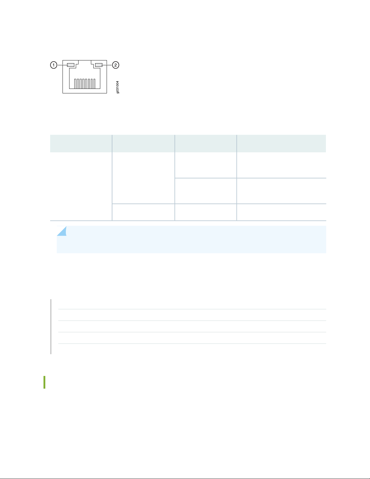
Figure 2: SRX100 Services Gateway Ethernet Port LEDs
The Table 6 on page 9 applies only to the TX/RX/LINK LED marked 1. Table 6 on page 9 describes the
states of this LED.
Table 6: SRX100 Services Gateway Built-In Ethernet Port LEDs
DescriptionStateColorFunction
9
BlinkingGreenTX/RX/LINK
Steady
Link is active. Data communication
is taking place.
Link is active. No data
communication is taking place.
Link is inactive.OffUnlit
NOTE: The LED marked as 2 in Figure 2 on page 9 is not functional in this release.
RELATED DOCUMENTATION
SRX100 Services Gateway Specifications | 21
SRX100 Services Gateway Front Panel and Back Panel Views | 12
SRX100 Services Gateway Built-In Interfaces | 14
SRX100 Services Gateway Boot Devices and Dual-Root Partitioning Scheme | 10
SRX100 Services Gateway Power Supply | 9
SRX100 Services Gateway Power Supply
The power supply for the SRX100 Services Gateway is external. You must use the power supply adapter
provided by Juniper Networks to provide power to the services gateway.
Page 25

RELATED DOCUMENTATION
SRX100 Services Gateway Specifications | 21
SRX100 Services Gateway Front Panel and Back Panel Views | 12
SRX100 Services Gateway LEDs | 6
SRX100 Services Gateway Built-In Interfaces | 14
SRX100 Services Gateway Boot Devices and Dual-Root Partitioning Scheme | 10
Monitoring the SRX100 Services Gateway Power System | 103
SRX100 Services Gateway Electrical and Power Requirements | 29
SRX100 Services Gateway Boot Devices and Dual-Root Partitioning Scheme
IN THIS SECTION
10
Boot Devices | 10
Dual-Root Partitioning Scheme | 10
This topic includes the following sections:
Boot Devices
The SRX100 Services Gateway can boot from the following storage media (in the order of priority):
Internal NAND Flash (default; always present)
•
USB storage key (alternate)
•
Dual-Root Partitioning Scheme
Dual-root partitions allow the SRX100 Services Gateways to remain functional if there is file system
corruption and facilitate easy recovery of the corrupted file system.
The dual-root partitioning scheme keeps the primary and backup Junos OS images in two independently
bootable root partitions. If the primary root partition becomes corrupted, the system will be able to boot
from the backup Junos OS image located in the other root partition and remain fully functional.
Page 26

When the SRX100 Services Gateway powers up, it tries to boot the Junos OS from the default storage
media. If the device fails to boot from the default storage media, it tries to boot from the alternate storage
media. With the dual-root partitioning scheme, the SRX100 Services Gateway first tries to boot the Junos
OS from the primary root partition and then from the backup root partition on the default storage media.
If both primary and backup root partitions of a media fail to boot, then the device tries to boot from the
next available type of storage media. The SRX100 Services Gateway remains fully functional even if it
boots the Junos OS from the backup root partition of storage media.
NOTE: SRX Series devices that ship from the factory with Junos OS Release 10.0 are formatted
with the dual-root partitioning scheme.
The SRX100 Services Gateways that are running Junos OS Release 9.6 or earlier use the single-root
partitioning scheme. While upgrading these devices to Junos OS Release 10.0, you can choose to format
the storage media with dual-root partitions (strongly recommended) or retain the existing single-root
partitioning.
11
For instructions on upgrading to Junos OS Release 10.0, see the following topics:
Initial Configuration for Security Devices
•
Monitoring and Troubleshooting for Security Devices
•
RELATED DOCUMENTATION
Installation Overview for the SRX100 Services Gateway | 36
SRX100 Services Gateway Software Configuration Overview | 65
Page 27
CHAPTER 3
g031001
Chassis Description
IN THIS CHAPTER
SRX100 Services Gateway Front Panel and Back Panel Views | 12
SRX100 Services Gateway Built-In Interfaces | 14
SRX100 Services Gateway Front Panel and Back Panel Views
12
IN THIS SECTION
SRX100 Services Gateway Front Panel | 12
SRX100 Services Gateway Back Panel | 13
This topic contains views of the front and back panels of the SRX100 Services Gateway. This topic includes
the following sections:
SRX100 Services Gateway Front Panel
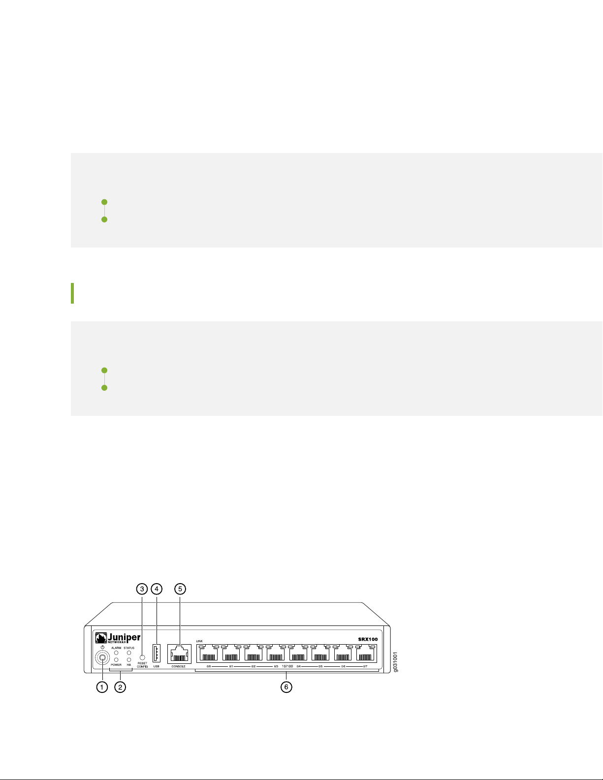
Figure 3 on page 12 shows the front panel of the SRX100 Services Gateway.
Figure 3: SRX100 Services Gateway Front Panel
Page 28
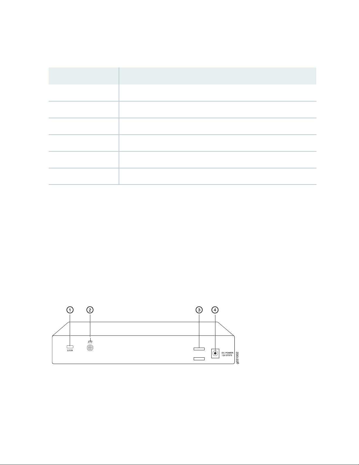
Table 7 on page 13 lists the front panel components of the services gateway.
g031002
Table 7: SRX100 Services Gateway Front Panel Components
ComponentNumber
Power button1
LEDs: Alarm, Status, Power, HA2
Reset Config button3
Universal serial bus (USB) port4
Console port5
Fast Ethernet ports6
13
For more information on the front panel components, see the following topics:
SRX100 Services Gateway Built-In Interfaces on page 14
•
SRX100 Services Gateway LEDs on page 6
•
SRX100 Services Gateway Boot Devices and Dual-Root Partitioning Scheme on page 10
•
SRX100 Services Gateway Back Panel
Figure 4 on page 13 illustrates the back panel of the SRX100 Services Gateway.
Figure 4: SRX100 Services Gateway Back Panel
Table 8 on page 14 lists the components available on the back panel of the SRX100 Services Gateway.
Page 29

Table 8: SRX100 Services Gateway Back Panel
ComponentNumber
Lock1
Grounding point2
Cable tie holder3
Power supply point4
NOTE: The cable tie holder provides support for holding the power cord on the power supply
point.
The lock provides the option to lock and secure the device to the installation site.
14
RELATED DOCUMENTATION
SRX100 Services Gateway Specifications | 21
SRX100 Services Gateway Built-In Interfaces | 14
SRX100 Services Gateway LEDs | 6
SRX100 Services Gateway Boot Devices and Dual-Root Partitioning Scheme | 10
SRX100 Services Gateway Power Supply | 9
SRX100 Services Gateway Built-In Interfaces
Table 9 on page 15 summarizes the interface ports supported on the SRX100 Services Gateway.
Page 30

Table 9: SRX100 Services Gateway Built-In Hardware Interfaces
15
DescriptionSpecificationsInterface Type
Fast Ethernet
Universal Serial Bus (USB)
The Fast Ethernet ports:
Consist of eight fixed ports
•
Are labeled as port 0/0 to port 0/7
•
on the front panel
Provide link speeds of 10/100
•
Mbps
Operate in full-duplex and
•
half-duplex modes
Support flow control
•
Support autonegotiation
•
Support autosensing
•
The USB port:
Consists of one port
•
Supports the following modes:
•
Full speed
•
High speed
•
Complies with USB revision 2.0
•
The Fast Ethernet ports can be used:
To provide LAN connectivity to
•
hubs, switches, local servers, and
workstations.
To forward incoming data packets
•
to the device.
To receive outgoing data packets
•
from the device.
The USB port can be used:
To support a USB storage device
•
that functions as a secondary boot
device in case of internal flash
failure on startup, if the USB
storage device is installed and
configured
Console
The console port:
Consists of one port
•
Uses an RJ-45 serial cable
•
connector
Supports the RS-232 (EIA-232)
•
standard
NOTE: You must install and
configure the USB storage device
on the USB port to use it as
secondary boot device.
Additionally, the USB device must
have Junos installed.
To provide the USB interfaces that
•
are used to communicate with
many types of Juniper-supported
USB storage devices
The console port can be used:
To provide the console interface.
•
To function as a management port
•
to log into a device directly.
To configure the device using the
•
CLI.
Page 31

NOTE: The Reset Config button is used to remove the current configuration and reset the device
to the default configuration.
The button is recessed in the front panel to prevent it from being pressed accidentally.
CAUTION: Pressing and holding the Reset Config button for 15 seconds or more
deletes all configurations on the device and loads and commits the factory configuration.
RELATED DOCUMENTATION
SRX100 Services Gateway Specifications | 21
16
SRX100 Services Gateway Front Panel and Back Panel Views | 12
SRX100 Services Gateway LEDs | 6
SRX100 Services Gateway Boot Devices and Dual-Root Partitioning Scheme | 10
SRX100 Services Gateway Power Supply | 9
Page 32

2
PART
Site Planning and Specifications
Planning and Preparing the Site | 18
Power Requirements and Specifications | 27
Cable Specifications and Pinouts | 31
Page 33

CHAPTER 4
Planning and Preparing the Site
IN THIS CHAPTER
Site Preparation Checklist for the SRX100 Services Gateway | 18
General Site Guidelines for Installing the SRX100 Services Gateway | 21
SRX100 Services Gateway Specifications | 21
SRX100 Services Gateway Cabinet Requirements | 23
SRX100 Services Gateway Rack Requirements | 24
Clearance Requirements for Airflow and Hardware Maintenance of the SRX100 Services Gateway | 25
18
Site Preparation Checklist for the SRX100 Services Gateway
The checklist in Table 10 on page 18 summarizes the tasks you need to perform when preparing a site for
installing the SRX100 Services Gateway.
Table 10: Site Preparation Checklist for Services Gateway Installation
Additional
NotesDatePerformed By
Environment
Verify that environmental
factors such as temperature
and humidity do not exceed
device tolerances.
Power
InformationItem or Task
“SRX100 Services
Gateway
Specifications” on
page 21
Page 34

Table 10: Site Preparation Checklist for Services Gateway Installation (continued)
Additional
InformationItem or Task
19
NotesDatePerformed By
Measure the distance
•
between the external
power sources and the
device installation site.
Locate sites for connection
•
of system grounding.
Calculate the power
•
consumption and
requirements.
Rack Requirements
Verify that your rack meets
the minimum requirements.
Rack Installation
“SRX100 Services
Gateway Site
Electrical Wiring
Guidelines” on
page 27
“SRX100 Services
Gateway Power
Specifications and
Requirements” on
page 29
“SRX100 Services
Gateway Rack
Requirements” on
page 24
Plan the rack location,
•
including required space
clearances.
Secure the rack to the floor
•
and building structure.
Cabinet Requirements
Verify that your cabinet
•
meets the minimum
requirements.
Plan the cabinet location,
•
including required space
clearances.
Wall Installation
“Preparing the
SRX100 Services
Gateway for
Rack-Mount
Installation” on
page 43
“SRX100 Services
Gateway Cabinet
Requirements” on
page 23
Page 35

Table 10: Site Preparation Checklist for Services Gateway Installation (continued)
Additional
InformationItem or Task
20
NotesDatePerformed By
Verify that the area
•
selected meets the
minimum requirements.
Verify that you have the
•
required hardware to
proceed with the
installation.
Desktop Installation
Verify that the area
•
selected meets the
minimum requirements.
Plan the installation
•
location, including required
space clearances and
airflow requirements.
Cables
Acquire cables and
•
connectors.
Review the maximum
•
distance allowed for each
cable. Choose the length
of cable based on the
distance between the
hardware components
being connected.
Plan the cable routing and
•
management.
“Preparing the
SRX100 Services
Gateway for
Wall-Mount
Installation” on
page 45
“Preparing the
SRX100 Services
Gateway for
Desk-Mount
Installation” on
page 44
“Interface Cable
and Wire
Specifications for
the SRX100
Services Gateway”
on page 31
RELATED DOCUMENTATION
SRX100 Services Gateway Specifications | 21
SRX100 Services Gateway Safety Requirements, Warnings, and Guidelines | 125
Installation Overview for the SRX100 Services Gateway | 36
General Site Guidelines for Installing the SRX100 Services Gateway | 21
Page 36

SRX100 Services Gateway Cabinet Requirements | 23
SRX100 Services Gateway Rack Requirements | 24
Clearance Requirements for Airflow and Hardware Maintenance of the SRX100 Services Gateway | 25
General Site Guidelines for Installing the SRX100 Services Gateway
Keep the following precautions in mind to help you plan an acceptable operating environment for your
SRX100 Services Gateway and avoid environmentally caused equipment failures:
For the operating temperature of the services gateway to be optimal, the airflow around the chassis
•
must be unrestricted. Allow sufficient clearance between the front and back of the chassis and adjacent
equipment. Ensure that there is adequate circulation in the installation location.
Follow the ESD procedures to avoid damaging equipment. Static discharge can cause components to
•
fail completely or intermittently over time.
21
NOTE: The SRX100 Services Gateway does not include a fan and does not generate any acoustic
noise.
RELATED DOCUMENTATION
SRX100 Services Gateway Safety Requirements, Warnings, and Guidelines | 125
SRX100 Services Gateway Cabinet Requirements | 23
SRX100 Services Gateway Rack Requirements | 24
Clearance Requirements for Airflow and Hardware Maintenance of the SRX100 Services Gateway | 25
SRX100 Services Gateway Specifications
The SRX100 Services Gateway chassis is a rigid sheet metal structure that houses all the other hardware
components (see Figure 5 on page 22).
Table 11 on page 22 provides information on the physical specifications of the device.
Page 37

Table 11: SRX100 Services Gateway Specifications
ValueSpecification
1.38 in. (35 mm)Chassis height
8.5 in. (216 mm)Chassis width
5.79 in. (147 mm)Chassis depth
1.86 lb (844 g)Chassis weight
22
Average power consumption
Temperature
Maximum thermal output
Figure 5: SRX100 Services Gateway
SRX100 Services Gateway Low Memory model: 10 watts
•
SRX100 Services Gateway High Memory model: 10 watts
•
Normal operation ensured in temperature range of 32°F (0°C) to 104°F
(+40°C)
Nonoperating storage temperature in shipping container: –40°F (–40°C)
to 158°F (70°C)
NOTE: The SRX100 Services Gateway operating temperature is 35°C
when installed in a rack.
The maximum thermal values for the two models of services gateways
are as follows:
Low Memory — AC power: 80 BTU/hour (21.5 W)
•
High Memory — AC power: 80 BTU/hour (21.5 W)
•
NOTE: These specifications are estimates and subject to change.
Page 38

CAUTION: Before removing or installing components of a functioning services gateway,
attach an electrostatic discharge (ESD) strap to an ESD point and place the other end
of the strap around your bare wrist. Failure to use an ESD strap could result in damage
to the services gateway.
RELATED DOCUMENTATION
SRX100 Services Gateway Description | 2
SRX100 Services Gateway Front Panel and Back Panel Views | 12
Monitoring the SRX100 Services Gateway Components Using LEDs | 100
SRX100 Services Gateway Electrical Safety Guidelines and Warnings | 150
23
SRX100 Services Gateway Cabinet Requirements
The SRX100 Services Gateway can be installed in a standard 31.5 in. (800 mm) or larger enclosed cabinet.
Table 12 on page 23 provides the details on cabinet size, clearance, and airflow requirements.
Table 12: SRX100 Services Gateway Cabinet Requirements
Cabinet
Requirements
Cabinet size
Clearance
requirements
Specifications
19 in. (48.3 cm) as defined in Cabinets, Racks, Panels, and Associated Equipment (document
number EIA-310–D) published by the Electronics Industry Association (http://www.eia.org).
You can mount the gateway horizontally in the cabinet.
The cabinet is at least 1 U (1.75 in. or 4.5 cm) high.
•
The outer edges of the mounting brackets extend the width of either chassis to 19 in.
•
(48.3 cm), and the front of the chassis extends approximately 0.5 in. (1.27 cm) beyond
the mounting brackets.
The minimum total clearance inside the cabinet is 30.7 in. (78 cm) between the inside of
•
the front door and the inside of the rear door.
NOTE: The holes for the mounting brackets chassis are spaced 1.25 in. (3.2 cm) apart,
measured from the center of the hole.
Page 39

Table 12: SRX100 Services Gateway Cabinet Requirements (continued)
Cabinet
Requirements
Specifications
24
Cabinet airflow
requirements
Ensure sufficient ventilation through the cabinet is sufficient to prevent overheating.
•
Ensure adequate cool air supply to dissipate the thermal output of the device.
•
Install the device as close as possible to the front of the cabinet so that the cable
•
management system clears the inside of the front door. Installing the chassis close to the
front of the cabinet maximizes the clearance in the rear of the cabinet for critical airflow.
Route and dress all cables to minimize the blockage of airflow to and from the chassis.
•
NOTE: A cabinet larger than the minimum required provides better airflow and reduces
the chance of overheating.
RELATED DOCUMENTATION
General Site Guidelines for Installing the SRX100 Services Gateway | 21
SRX100 Services Gateway Rack Requirements | 24
Clearance Requirements for Airflow and Hardware Maintenance of the SRX100 Services Gateway | 25
SRX100 Services Gateway Rack Requirements
The services gateway can be installed in a rack. Many types of racks are acceptable, including front-mount
racks and four-post (telco) racks.
NOTE: The services gateway cannot be center mounted in a rack.
Table 13 on page 24 provides the details of requirements for rack size, clearance, airflow, spacing of
mounting brackets and flange holes, and connecting to the building structure.
Table 13: Rack Requirements for the Services Gateway
SpecificationsRack Requirement
Size
A 19 in. (48.3 cm) rack as defined in Cabinets, Racks, Panels, and Associated Equipment
(document number EIA-310-D) published by the Electronics Industry Association
(http://www.eia.org).
Page 40

Table 13: Rack Requirements for the Services Gateway (continued)
SpecificationsRack Requirement
25
Clearance
Spacing of Mounting
Bracket and Flange Holes
Connecting to the
Building Structure
The outer edges of the mounting brackets extend the width of either chassis to 19 in.
•
(48.3 cm).
The front of the chassis extends approximately 0.5 in. (1.27 cm) beyond the mounting
•
ears.
Maximum permissible ambient temperature when two devices are placed side by
•
side in a 19 in. rack is 40° C.
The holes within each rack set are spaced at 1 U [1.75 in. (4.5 cm)]. The device can
•
be mounted in any rack that provides holes or hole patterns spaced at 1-U [1.75 in.
(4.5 cm)] increments.
The mounting brackets and front-mount flanges used to attach the chassis to a rack
•
are designed to fasten to holes spaced at rack distances of 1 U (1.75 in.).
The mounting holes in the mounting brackets provided with the device are spaced
•
1.25 in. (3.2 cm) apart (top and bottom mounting hole).
Always secure the rack in which you are installing the services gateway to the structure
of the building. If your geographical area is subject to earthquakes, bolt the rack to the
floor. For maximum stability, also secure the rack to ceiling brackets.
RELATED DOCUMENTATION
General Site Guidelines for Installing the SRX100 Services Gateway | 21
SRX100 Services Gateway Cabinet Requirements | 23
Clearance Requirements for Airflow and Hardware Maintenance of the SRX100 Services Gateway | 25
Clearance Requirements for Airflow and Hardware Maintenance of the SRX100 Services Gateway
When planning the installation site for the SRX100 Services Gateway, you need to allow sufficient clearance
around the device.
When planning the installation site for the services gateway, consider the following:
For the operating temperature of the services gateway to be optimal, the airflow around the chassis
•
must be unrestricted.
Page 41

For service personnel to remove and install hardware components, there must be adequate space at the
•
front and back of the device. Allow at least 24 in. (61 cm) both in front of and behind the device.
If you are mounting the device in a rack with other equipment, or if you are placing it on the desktop
•
near other equipment, ensure that the exhaust from other equipment does not blow into the intake
vents of the chassis.
Table 14 on page 26 provides information on the clearance requirements for maintaining the optimum
airflow and the distances for facilitating easy maintenance of the device.
Table 14: Clearance Requirements for the SRX100 Services Gateway
Requirement for ClearanceRecommended ClearanceLocation
26
2.5 in. (6.35 cm)Front of the chassis
2.5 in. (6.35 cm)Rear of the chassis
2.5 in. (6.35 cm)Between front-mounting flange and
rack or cabinet edge
2.5 in. (6.35 cm)Between side of the chassis and any
non-heat-producing surface such as
a wall or cabinet side
0.4 in. (1 cm)Between side of the chassis and
devices that have fans or blowers
Space for service personnel to remove
and install hardware components
Space for service personnel to remove
and install hardware components
Space for cable management and
organization
Space for the cooling system to function
properly and to maintain unrestricted
airflow around the chassis
Space for the cooling system to function
properly and to maintain unrestricted
airflow around the chassis
NOTE: The air vents are provided on the sides of the chassis for the SRX100 Services Gateway.
RELATED DOCUMENTATION
General Site Guidelines for Installing the SRX100 Services Gateway | 21
SRX100 Services Gateway Cabinet Requirements | 23
SRX100 Services Gateway Rack Requirements | 24
Page 42

CHAPTER 5
Power Requirements and Specifications
IN THIS CHAPTER
SRX100 Services Gateway Site Electrical Wiring Guidelines | 27
SRX100 Services Gateway Electrical and Power Requirements | 29
SRX100 Services Gateway Power Specifications and Requirements | 29
SRX100 Services Gateway Site Electrical Wiring Guidelines
27
Table 15 on page 28 describes the factors you must consider while planning the electrical wiring for the
services gateway at your site.
CAUTION: It is particularly important to provide a properly grounded and shielded
environment and to use electrical surge-suppression devices.
CAUTION: For devices with AC power supplies, an external surge protective device
(SPD) must be used at the AC power source.
Page 43

Table 15: Site Electrical Wiring Guidelines for the Services Gateway
GuidelineSite Wiring Factor
28
Signaling Limitations
Radio Frequency Interference
(RFI)
Electromagnetic Compatibility
(EMC)
To ensure that signaling functions optimally:
Install wires correctly.
•
Improperly installed wires can emit radio interference.
Do not exceed the recommended distances or pass wires between buildings.
•
The potential for damage from lightning strikes increases if wires exceed
recommended distances or if wires pass between buildings.
Shield all conductors.
•
The electromagnetic pulse (EMP) caused by lightning can damage unshielded
conductors and destroy electronic devices.
To reduce or eliminate the emission of RFI from your site wiring:
Use twisted-pair cable with a good distribution of grounding conductors.
•
Use a high-quality twisted-pair cable with one ground conductor for each data
•
signal when applicable, if you must exceed the recommended distances.
Provide a properly grounded and shielded environment and use electrical
surge-suppression devices.
Strong sources of electromagnetic interference (EMI) can cause the following
damage:
Destroy the signal drivers and receivers in the device
•
Conduct power surges over the lines into the equipment, resulting in an
•
electrical hazard
NOTE: If your site is susceptible to problems with EMC, particularly from
lightning or radio transmitters, you may want to seek expert advice.
CAUTION: To comply with intrabuilding lightning/surge requirements, the intrabuilding
wiring must be shielded. The shielding for the wiring must be grounded at both ends.
RELATED DOCUMENTATION
General Site Guidelines for Installing the SRX100 Services Gateway | 21
Monitoring the SRX100 Services Gateway Power System | 103
Page 44

SRX100 Services Gateway Electrical and Power Requirements | 29
SRX100 Services Gateway Power Specifications and Requirements | 29
SRX100 Services Gateway Electrical and Power Requirements
This topic provides information on the factors you must consider while planning the electrical wiring and
power availability at your site. These requirements cover the following areas:
Power specifications and requirements for the device
•
Electrical wiring guidelines for the device installation site
•
Power, connection, and power cord specifications for the device
•
Grounding guidelines and specifications for the device
•
29
RELATED DOCUMENTATION
SRX100 Services Gateway Site Electrical Wiring Guidelines | 27
Clearance Requirements for Airflow and Hardware Maintenance of the SRX100 Services Gateway | 25
Installation Overview for the SRX100 Services Gateway | 36
Interface Cable and Wire Specifications for the SRX100 Services Gateway | 31
SRX100 Services Gateway Power Specifications and Requirements
The AC power system electrical specifications for the SRX100 Services Gateway are listed in
Table 16 on page 29.
Table 16: Power System Electrical Specifications for the SRX100 Services Gateway
SpecificationPower Requirement
100 to 240 VACAC input voltage
50 to 60 HzAC input line frequency
1 A maximumAC system current rating
Page 45

WARNING: The AC power cord for the services gateway is intended for use with the
device only and not for any other use.
RELATED DOCUMENTATION
Clearance Requirements for Airflow and Hardware Maintenance of the SRX100 Services Gateway | 25
SRX100 Services Gateway Site Electrical Wiring Guidelines | 27
Monitoring the SRX100 Services Gateway Power System | 103
Maintaining the SRX100 Services Gateway Hardware Components | 95
30
Page 46

CHAPTER 6
Cable Specifications and Pinouts
IN THIS CHAPTER
Interface Cable and Wire Specifications for the SRX100 Services Gateway | 31
RJ-45 Connector Pinouts for the SRX100 Services Gateway Ethernet Port | 32
RJ-45 Connector Pinouts for the SRX100 Services Gateway Console Port | 32
Interface Cable and Wire Specifications for the SRX100 Services Gateway
31
Table 17 on page 31 lists the specifications for the cables that connect to ports.
Table 17: Cable and Wire Specifications for Ports
Maximum
LengthCable/Wire RequiredCable SpecificationPort
RS-232 (EIA-232) serial cableConsole port
DB-9/RJ-45 connectors
Ethernet
port
CAT-5e (Category 5) cable or
equivalent suitable for
100BASE-T operation
RJ-45/RJ-45 connectors
RELATED DOCUMENTATION
RJ-45 Connector Pinouts for the SRX100 Services Gateway Ethernet Port | 32
RJ-45 Connector Pinouts for the SRX100 Services Gateway Console Port | 32
Device
Receptacle
RJ-456 ft (1.83 m)One 6-ft (1.83-m) length with
RJ-45328 ft (100 m)One 15-ft (4.57-m) length with
Page 47

RJ-45 Connector Pinouts for the SRX100 Services Gateway Ethernet Port
Figure 6 on page 32 shows the RJ-45 cable connector pinouts for Ethernet ports.
Figure 6: Ethernet Cable Connector (RJ-45)
Table 18 on page 32 describes the RJ-45 connector pinouts for the Ethernet port.
Table 18: RJ-45 Connector Pinouts for the Services Gateway Ethernet Port
SignalPin
TX+1
32
TX -2
RX+3
Termination network4
Termination network5
RX-6
Termination network7
Termination network8
RELATED DOCUMENTATION
Interface Cable and Wire Specifications for the SRX100 Services Gateway | 31
RJ-45 Connector Pinouts for the SRX100 Services Gateway Console Port | 32
RJ-45 Connector Pinouts for the SRX100 Services Gateway Console Port
Figure 7 on page 33 shows the RJ-45 connector pinouts for the console port.
Page 48

Figure 7: Console Cable Connector
Table 19 on page 33 describes the RJ-45 connector pinouts for the console port.
Table 19: RJ-45 Connector Pinouts for the Services Gateway Console Port
DescriptionSignalPin
Request to SendRTS1
Data Terminal ReadyDTR2
Transmit DataTXD3
Signal GroundGround4
33
Signal GroundGround5
Receive DataRXD6
Data Set ReadyDSR/DCD7
Clear to SendCTS8
RELATED DOCUMENTATION
Interface Cable and Wire Specifications for the SRX100 Services Gateway | 31
RJ-45 Connector Pinouts for the SRX100 Services Gateway Ethernet Port | 32
Page 49

3
PART
Initial Installation and Configuration
Installation Overview | 35
Unpacking the Services Gateway | 40
Installing the Mounting Hardware | 43
Installing the Services Gateway | 46
Grounding the SRX100 Services Gateway | 52
Connecting the SRX100 Services Gateway to External Devices | 55
Providing Power to the SRX100 Services Gateway | 60
Performing Initial Configuration | 65
Page 50

CHAPTER 7
Installation Overview
IN THIS CHAPTER
Installation Overview for the SRX100 Services Gateway | 36
Required Tools and Parts for Installing and Maintaining the SRX100 Services Gateway | 37
SRX100 Services Gateway Autoinstallation Overview | 38
35
Page 51

Installation Overview for the SRX100 Services Gateway
After you have prepared your installation site, you are ready to unpack and install the services gateway.
It is important to proceed through the installation process in the order shown in Table 20 on page 36.
Table 20: Installation Process Order for the SRX100 Services Gateway
For More Information, SeeProcessSteps
36
Review the safety guidelines.1
2
3
Verify that you have prepared your site for
the installation of the services gateway using
the checklist.
Follow the instructions for unpacking the
services gateway and verify that the parts
are received.
Prepare the services gateway for installation.4
Install the services gateway.5
“SRX100 Services Gateway Safety
Requirements, Warnings, and Guidelines” on
page 125
“Site Preparation Checklist for the SRX100
Services Gateway” on page 18
“Unpacking the SRX100 Services Gateway”
on page 40
“Preparing the SRX100 Services Gateway for
Rack-Mount Installation” on page 43
“Preparing the SRX100 Services Gateway for
Desk-Mount Installation” on page 44
“Preparing the SRX100 Services Gateway for
Wall-Mount Installation” on page 45
“Installing the SRX100 Services Gateway in
a Rack” on page 46
“Installing the SRX100 Services Gateway on
a Desk” on page 48
“Installing the SRX100 Services Gateway on
a Wall” on page 49
Connect cables to external devices.6
Connect the grounding cable.7
Power on the services gateway.8
“Connecting and Organizing Interface Cables
to the SRX100 Services Gateway” on page 55
“Grounding the SRX100 Services Gateway”
on page 52
“Powering On and Powering Off the SRX100
Services Gateway” on page 61
Page 52

RELATED DOCUMENTATION
Unpacking the SRX100 Services Gateway | 40
General Site Guidelines for Installing the SRX100 Services Gateway | 21
Preparing the SRX100 Services Gateway for Rack-Mount Installation | 43
Preparing the SRX100 Services Gateway for Desk-Mount Installation | 44
Preparing the SRX100 Services Gateway for Wall-Mount Installation | 45
Installing the SRX100 Services Gateway in a Rack | 46
Installing the SRX100 Services Gateway on a Desk | 48
Installing the SRX100 Services Gateway on a Wall | 49
Connecting and Organizing Interface Cables to the SRX100 Services Gateway | 55
Required Tools and Parts for Installing and Maintaining the SRX100 Services
37
Gateway
Table 21 on page 37 lists the tools and parts required to install and maintain the SRX100 Services Gateway.
Table 21: Required Tools and Parts for Installing and Maintaining the SRX100 Services Gateway
Related TopicTools and PartsTask
Installing the SRX100 Services
Gateway
Connecting the SRX100 Services
Gateway
Gateway
Phillips (+) screwdriver, numbers
•
1 and 3
Tie wrap
•
Electrostatic discharge (ESD)
grounding wrist strap
Phillips (+) screwdriver, number 1Grounding the SRX100 Services
“Installing the SRX100 Services
Gateway in a Rack” on page 46
“Installing the SRX100 Services
Gateway on a Desk” on page 48
“Installing the SRX100 Services
Gateway on a Wall” on page 49
“Connecting the SRX100 Services
Gateway to the Power Supply” on
page 60
“Grounding the SRX100 Services
Gateway” on page 52
Packing the SRX100 Services
Gateway
Electrostatic bag or antistatic mat,
•
for each component
Electrostatic discharge (ESD)
•
grounding wrist strap
“Packing the SRX100 Services
Gateway and Components for
Shipment” on page 113
Page 53

RELATED DOCUMENTATION
Unpacking the SRX100 Services Gateway | 40
Installing the SRX100 Services Gateway in a Rack | 46
Installing the SRX100 Services Gateway on a Desk | 48
Installing the SRX100 Services Gateway on a Wall | 49
Grounding the SRX100 Services Gateway | 52
Connecting the SRX100 Services Gateway to the Power Supply | 60
Packing the SRX100 Services Gateway and Components for Shipment | 113
SRX100 Services Gateway Autoinstallation Overview
The autoinstallation process begins any time a services gateway is powered on and cannot locate a valid
configuration file in the internal flash. Typically, a configuration file is unavailable when a services gateway
is powered on for the first time or if the configuration file is deleted from the internal flash. The
autoinstallation feature enables you to deploy multiple services gateways from a central location in the
network.
38
If you are setting up many devices, autoinstallation can help automate the configuration process by loading
configuration files onto new or existing devices automatically over the network. You can use either the
J-Web interface or the CLI to configure a device for autoinstallation.
For the autoinstallation process to work, you must store one or more host-specific or default configuration
files on a configuration server in the network and have a service available—typically Dynamic Host
Configuration Protocol (DHCP)—to assign an IP address to the services gateway.
Autoinstallation takes place automatically when you connect an Ethernet port on a new services gateway
to the network and power on the device. To simplify the process, you can explicitly enable autoinstallation
on a device and specify a configuration server, an autoinstallation interface, and a protocol for IP address
acquisition.
For more information about configuring autoinstallation, see the following topics:
Installation and Upgrade Guide
•
Network Monitoring and Troubleshooting
•
RELATED DOCUMENTATION
Connecting the SRX100 Services Gateway to the Power Supply | 60
Page 54

Grounding the SRX100 Services Gateway | 52
Powering On and Powering Off the SRX100 Services Gateway | 61
39
Page 55

CHAPTER 8
Unpacking the Services Gateway
IN THIS CHAPTER
Unpacking the SRX100 Services Gateway | 40
Verifying Parts Received with the SRX100 Services Gateway | 41
Unpacking the SRX100 Services Gateway
40
The SRX100 Services Gateway is shipped in a cardboard carton. The carton also contains an accessory
box and the SRX100 Services Gateway Quick Start.
NOTE: The device is maximally protected inside the shipping carton. Do not unpack it until you
are ready to begin installation.
To unpack the SRX100 Services Gateway:
1. Open the box in which the device is shipped.
2. Verify the parts received against the lists in “Verifying Parts Received with the SRX100 Services
Gateway” on page 41.
3. Store the shipping box and packing material in case you need to return or move the device at a later
time.
RELATED DOCUMENTATION
Required Tools and Parts for Installing and Maintaining the SRX100 Services Gateway | 37
Verifying Parts Received with the SRX100 Services Gateway | 41
Preparing the SRX100 Services Gateway for Rack-Mount Installation | 43
Preparing the SRX100 Services Gateway for Desk-Mount Installation | 44
Page 56

Preparing the SRX100 Services Gateway for Wall-Mount Installation | 45
Installation Overview for the SRX100 Services Gateway | 36
Verifying Parts Received with the SRX100 Services Gateway
The SRX100 Services Gateway shipment package contains a packing list. Check the parts in the shipment
against the items on the packing list. The packing list specifies the part numbers and descriptions of each
part in your order.
If any part is missing, contact your Juniper Networks customer service representative.
A fully configured SRX100 Services Gateway contains the chassis with installed components, listed in
Table 22 on page 41, and an accessory box, which contains the parts listed in Table 23 on page 41.
NOTE: The parts shipped with your device can vary depending on the configuration you ordered.
41
Table 22: Parts List for a Fully Configured SRX100 Services Gateway
QuantityComponent
1Chassis, with 8xFE ports
1Power supply adapter (30 W)
12-prong power cord
1DB-9 to RJ-45 adapter, straight through, 7 ft
Table 23: Accessory Parts List for the SRX100 Services Gateway
QuantityPart
1Juniper Networks Product Warranty
1End User License Agreement
1Quick Start
1Security Products Safety Guide
1Juniper Compliance Form Letter
Page 57

Table 23: Accessory Parts List for the SRX100 Services Gateway (continued)
QuantityPart
1Product Registration
NOTE: The mounting kits available for rack, desk, and wall installation of the SRX100 Services
Gateway must be ordered separately. Contact your Juniper Networks customer service
representative for more information.
RELATED DOCUMENTATION
Required Tools and Parts for Installing and Maintaining the SRX100 Services Gateway | 37
42
Unpacking the SRX100 Services Gateway | 40
Preparing the SRX100 Services Gateway for Rack-Mount Installation | 43
Preparing the SRX100 Services Gateway for Desk-Mount Installation | 44
Preparing the SRX100 Services Gateway for Wall-Mount Installation | 45
Page 58

CHAPTER 9
Installing the Mounting Hardware
IN THIS CHAPTER
Preparing the SRX100 Services Gateway for Rack-Mount Installation | 43
Preparing the SRX100 Services Gateway for Desk-Mount Installation | 44
Preparing the SRX100 Services Gateway for Wall-Mount Installation | 45
Preparing the SRX100 Services Gateway for Rack-Mount Installation
43
You can mount an SRX100 Services Gateway in four-post (telco) racks, enclosed cabinets, and open-frame
racks.
NOTE: The SRX100 Services Gateway cannot be center-mounted in racks.
Before mounting the SRX100 Services Gateway in a rack:
Verify that the installation site meets the requirements described in the site preparation checklist.
•
Verify that the racks or cabinets meet the specific requirements described in “SRX100 Services Gateway
•
Rack Requirements” on page 24.
Place the rack or cabinet in its permanent location, allowing adequate clearance for airflow and
•
maintenance, and secure it to the building structure. For more information, see “Clearance Requirements
for Airflow and Hardware Maintenance of the SRX100 Services Gateway” on page 25.
Remove the services gateway chassis from the shipping carton. For unpacking instructions, see “Unpacking
•
the SRX100 Services Gateway” on page 40.
Verify that you have the following parts available in your rack-mounting kit for the SRX100 Services
•
Gateway:
Rack-mount tray
•
Screws
•
Page 59

NOTE: The rack-mounting kit is not shipped with the device and must be ordered separately.
RELATED DOCUMENTATION
Unpacking the SRX100 Services Gateway | 40
Clearance Requirements for Airflow and Hardware Maintenance of the SRX100 Services Gateway | 25
SRX100 Services Gateway Rack Requirements | 24
Preparing the SRX100 Services Gateway for Desk-Mount Installation | 44
Preparing the SRX100 Services Gateway for Wall-Mount Installation | 45
44
Preparing the SRX100 Services Gateway for Desk-Mount Installation
You can mount an SRX100 Services Gateway on a desk or other level surface horizontally or vertically.
The four rubber feet attached to the chassis provide stability.
Before mounting an SRX100 Services Gateway on a desk or other level surface:
Verify that the site meets the requirements described in the site preparation checklist.
•
Place the desk in its permanent location, allowing adequate clearance for airflow and maintenance, and
•
secure it to the building structure.
Remove the services gateway chassis from the shipping carton. For unpacking instructions, see “Unpacking
•
the SRX100 Services Gateway” on page 40.
If you are mounting the device vertically on the desk, make sure that the following parts are available
•
in your vertical desk-mounting kit for the SRX100 Services Gateway:
Vertical stand
•
Screws
•
NOTE: The vertical desk-mounting kit is not shipped with the device and must be ordered
separately.
Page 60

RELATED DOCUMENTATION
Unpacking the SRX100 Services Gateway | 40
Clearance Requirements for Airflow and Hardware Maintenance of the SRX100 Services Gateway | 25
Preparing the SRX100 Services Gateway for Rack-Mount Installation | 43
Preparing the SRX100 Services Gateway for Wall-Mount Installation | 45
Preparing the SRX100 Services Gateway for Wall-Mount Installation
You can mount an SRX100 Services Gateway on a wall. The four rubber feet attached to the chassis provide
stability.
Before mounting an SRX100 Services Gateway on a wall:
Verify that the site meets the requirements described in “Site Preparation Checklist for the SRX100
•
Services Gateway” on page 18.
45
Remove the services gateway chassis from the shipping carton. For unpacking instructions, see “Unpacking
•
the SRX100 Services Gateway” on page 40.
Verify that you have the following parts available in your wall-mounting kit for the SRX100 Services
•
Gateway:
Wall-mounting brackets
•
Screws
•
NOTE: The wall-mounting kit is not shipped with the device and must be ordered separately.
RELATED DOCUMENTATION
Site Preparation Checklist for the SRX100 Services Gateway | 18
Unpacking the SRX100 Services Gateway | 40
Clearance Requirements for Airflow and Hardware Maintenance of the SRX100 Services Gateway | 25
Preparing the SRX100 Services Gateway for Rack-Mount Installation | 43
Preparing the SRX100 Services Gateway for Desk-Mount Installation | 44
Page 61

CHAPTER 10
Installing the Services Gateway
IN THIS CHAPTER
Installing the SRX100 Services Gateway in a Rack | 46
Installing the SRX100 Services Gateway on a Desk | 48
Installing the SRX100 Services Gateway on a Wall | 49
Installing the SRX100 Services Gateway in a Rack
46
You can front-mount two SRX100 Services Gateways in a rack. Many types of racks are acceptable,
including four-post (telco) racks, enclosed cabinets, and open-frame racks. For more information about
the type of rack or cabinet the SRX100 Services Gateway can be installed into, see “SRX100 Services
Gateway Rack Requirements” on page 24.
NOTE: If you are installing multiple devices in one rack, install the lowest one first and proceed
upward in the rack.
To install the device in a rack:
Page 62
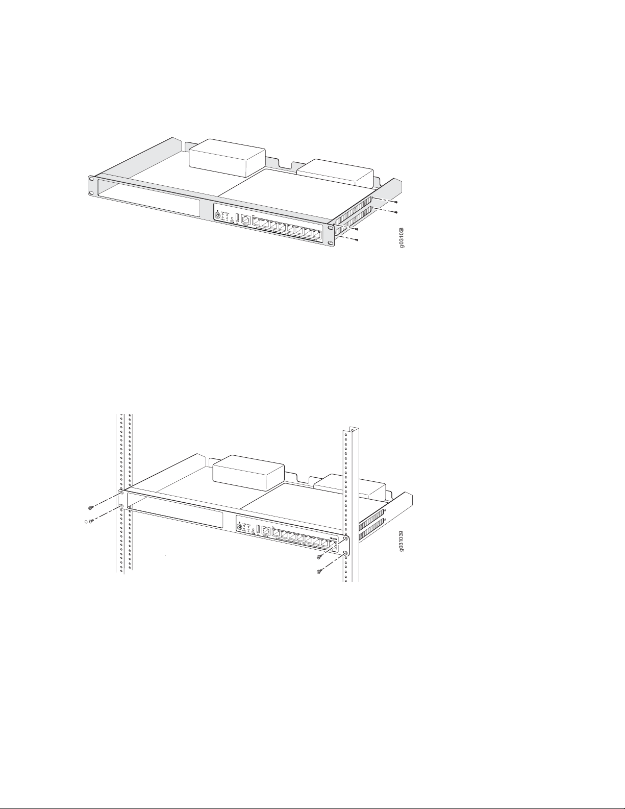
1. Position the two devices in the rack-mount tray as shown in Figure 8 on page 47.
g031038
g0310 39
Figure 8: Installing the SRX100 Services Gateway in a Rack
2. Use a number-1 Phillips screwdriver to install the screws that secure the device to the rack-mount tray.
3. Have one person grasp the sides of the rack-mount tray, lift it, and position it in the rack.
47
4. Align the bottom hole in each side of the rack-mount tray with a hole in each rack rail as shown in
Figure 9 on page 47, making sure the rack-mount tray is level.
Figure 9: Hanging the SRX100 Services Gateway in a Rack
5. Have a second person install a mounting screw into each of the two aligned holes. Use a number-3
Phillips screwdriver to install the mounting screws.
6. Install the second screw in each side of the rack-mount tray.
7. Verify that the mounting screws on one side of the rack-mount tray are aligned with the mounting
screws on the opposite side and that the tray is level.
Page 63

NOTE: The rack-mounting kit is not shipped with the device and must be ordered separately.
RELATED DOCUMENTATION
Required Tools and Parts for Installing and Maintaining the SRX100 Services Gateway | 37
Preparing the SRX100 Services Gateway for Rack-Mount Installation | 43
SRX100 Services Gateway Rack Requirements | 24
Connecting the SRX100 Services Gateway to the Power Supply | 60
Clearance Requirements for Airflow and Hardware Maintenance of the SRX100 Services Gateway | 25
SRX100 Services Gateway Safety Requirements, Warnings, and Guidelines | 125
Installing the SRX100 Services Gateway on a Desk | 48
48
Installing the SRX100 Services Gateway on a Wall | 49
Installing the SRX100 Services Gateway on a Desk
You can install the SRX100 Services Gateway on a desk, table, or other level surface. The device is shipped
with the rubber feet attached. The rubber feet are necessary to stabilize the device on the desk.
You can install the device in a horizontal or vertical position.
NOTE: The desk-mounting kit is not shipped with the device and must be ordered separately.
Horizontal Desk Mounting
The horizontal position is the standard installation position and does not require the vertical installation
kit.
To install the device in a horizontal position:
1. Make sure that the rubber feet are attached to the chassis.
2. Place the device on a desk with the Juniper Networks logo embossed on the top cover facing up.
Vertical Desk Mounting
Page 64

The vertical position requires the vertical installation kit, which consists of a vertical installation stand.
To install the device in a vertical position:
1. Place the device on a flat and level surface with the Juniper Networks logo on the front panel facing
up, as shown in Figure 10 on page 49.
Figure 10: Installing the SRX100 Services Gateway on a Desk
49
2. Attach the vertical stand to the right side of the chassis as shown in Figure 10 on page 49.
3. Place the chassis vertically on the desk with the stand resting on the desk.
RELATED DOCUMENTATION
Required Tools and Parts for Installing and Maintaining the SRX100 Services Gateway | 37
Preparing the SRX100 Services Gateway for Desk-Mount Installation | 44
SRX100 Services Gateway Safety Requirements, Warnings, and Guidelines | 125
Installing the SRX100 Services Gateway in a Rack | 46
Installing the SRX100 Services Gateway on a Wall | 49
Installing the SRX100 Services Gateway on a Wall
You can install the SRX100 Services Gateway on a wall. The device is shipped with the rubber feet attached.
The rubber feet help stabilize the device on the wall and enhance airflow.
Page 65

NOTE: The wall-mounting kit is not shipped with the device and must be ordered separately.
To install the device on a wall:
1. Place the device on a flat and level surface with the Juniper Networks logo embossed on the top cover
facing up.
2. Position a mounting bracket on each side of the chassis as shown in Figure 11 on page 50.
Figure 11: Installing the SRX100 Services Gateway on a Wall
50
3. Use a number–1 Phillips screwdriver to install the screws that secure the mounting brackets to the
chassis.
4. If you are using wall anchors to support the chassis, install two pairs of anchors on the wall with mounting
brackets attached.
5. Have one person grasp the sides of the device, lift it, and position it on the wall.
6. Have a second person install two pairs of mounting screws through the bracket holes on either side of
the device to secure it to the wall.
7. Verify that the mounting screws on one side are aligned with the mounting screws on the opposite
side and that the device is level (see Figure 12 on page 51).
Page 66

Figure 12: Hanging the SRX100 Services Gateway on a Wall
51
RELATED DOCUMENTATION
Required Tools and Parts for Installing and Maintaining the SRX100 Services Gateway | 37
Preparing the SRX100 Services Gateway for Wall-Mount Installation | 45
SRX100 Services Gateway Safety Requirements, Warnings, and Guidelines | 125
Installing the SRX100 Services Gateway on a Desk | 48
Installing the SRX100 Services Gateway in a Rack | 46
Connecting the SRX100 Services Gateway to the Power Supply | 60
Page 67

CHAPTER 11
Grounding the SRX100 Services Gateway
IN THIS CHAPTER
Grounding the SRX100 Services Gateway | 52
Grounding the SRX100 Services Gateway
To meet safety and electromagnetic interference (EMI) requirements and to ensure proper operation, the
SRX100 Services Gateway must be adequately grounded before power is connected.
52
Figure 13 on page 52 illustrates how a grounding cable connects to the services gateway.
Figure 13: Grounding the SRX100 Services Gateway
You ground the device by connecting a grounding cable to earth ground and then attaching it to the chassis
grounding points using one M3 screw.
CAUTION: Before device installation begins, a licensed electrician must attach a cable
lug to the grounding and power cables that you use. A cable with an incorrectly attached
lug can damage the device (for example, by causing a short circuit).
Page 68

Table 24 on page 53 lists the grounding components of the SRX100 Services Gateway.
Table 24: SRX100 Services Gateway Grounding Components
ComponentNumber
Grounding point on the chassis1
Grounding lug2
Grounding screw (M3 screw)3
Table 25 on page 53 lists the specifications of the grounding cable used with the device.
Table 25: Grounding Cable Specifications for the Services Gateway
SpecificationGrounding Requirement
14 AWG single-strand wire cableGrounding cable
53
Up to 4 AAmperage of grounding cable
Ring-type, vinyl-insulated TV14-6R lug or equivalentGrounding lug
To ground the device:
1. Connect the grounding cable to a proper earth ground.
2. Verify that a licensed electrician has attached the cable lug to the grounding cable.
3. Place the grounding cable lug over the grounding point on the middle rear of the chassis.
4. Secure the grounding cable lug to the grounding point with the screw as shown in Figure 13 on page 52.
5. Dress the grounding cable and verify that it does not touch or block access to the services gateway
components and that it does not drape where people could trip on it.
NOTE: The device should be permanently connected to ground during operation.
RELATED DOCUMENTATION
Page 69

Connecting the SRX100 Services Gateway to the Power Supply | 60
Connecting and Organizing Interface Cables to the SRX100 Services Gateway | 55
SRX100 Services Gateway General Safety Guidelines and Warnings | 119
Powering On and Powering Off the SRX100 Services Gateway | 61
Using the Reset Config Button on the SRX100 Services Gateway | 104
Changing the Reset Config Button Behavior on the SRX100 Services Gateway | 106
54
Page 70

CHAPTER 12
Connecting the SRX100 Services Gateway to External Devices
IN THIS CHAPTER
Connecting and Organizing Interface Cables to the SRX100 Services Gateway | 55
Connecting the Modem at the SRX100 Services Gateway End | 56
Connecting the Modem to the Console Port on the SRX100 Services Gateway | 57
Connecting to the CLI at the User End for the SRX100 Services Gateway | 58
55
Connecting and Organizing Interface Cables to the SRX100 Services Gateway
You can connect the interfaces installed in the services gateway to various network media. Each type of
interface on the services gateway uses a particular medium to transmit data. You must configure each
network interface before it can operate on the device.
To connect and organize an interface cable for the device:
1. Have ready a length of the type of cable used by the interface.
2. Insert the cable connector into the cable connector port on the interface faceplate.
3. Arrange network cables as follows to prevent them from dislodging or developing stress points:
Secure cables so that they are not supporting their own weight as they hang to the floor.
•
Place excess cable out of the way in neatly coiled loops.
•
Use fasteners to maintain the shape of cable loops.
•
RELATED DOCUMENTATION
Connecting the SRX100 Services Gateway to the Power Supply | 60
Page 71

Grounding the SRX100 Services Gateway | 52
Interface Cable and Wire Specifications for the SRX100 Services Gateway | 31
SRX100 Services Gateway Installation Safety Guidelines and Warnings | 129
Connecting the Modem at the SRX100 Services Gateway End
NOTE: These instructions use Hayes-compatible modem commands to configure the modem.
If your modem is not Hayes-compatible, refer to the documentation for your modem and enter
the equivalent modem commands.
To configure the modem on the services gateway end:
1. Connect the modem to a PC or laptop computer.
56
2. Power on the modem.
3. From the PC or laptop computer, start your asynchronous terminal emulation application (such as
Microsoft Windows HyperTerminal), and select the COM port to which the modem is connected (for
example, COM1).
4. Configure the port settings as shown in Table 26 on page 56.
Table 26: Port Settings for Configuring the Modem on the Services Gateway End
ValuePort Setting
9600Bits per second
8Data bits
NoneParity
1Stop bits
NoneFlow control
5. In the HyperTerminal window, enter AT.
Page 72

An OK response verifies that the modem can communicate successfully with the COM port on the PC
or laptop.
For more information on the AT commands, see Administration Guide for Security Devices.
6. Configure the modem to answer a call on the first ring by entering ATS0=1.
7. Configure the modem to accept modem control DTR signals by entering AT&D1.
8. Disable flow control by entering AT&K0.
9. Save modem settings by entering AT&W.
RELATED DOCUMENTATION
Connecting the Modem to the Console Port on the SRX100 Services Gateway | 57
57
Connecting to the CLI at the User End for the SRX100 Services Gateway | 58
Connecting the Modem to the Console Port on the SRX100 Services Gateway
To connect the dial-up modem to the console port on the services gateway:
1. Turn off power to the services gateway.
2. Turn off power to the modem.
3. Plug one end of the Ethernet cable supplied with your services gateway into the console port on the
services gateway.
4. Plug the other end of the CAT-5e cable (Ethernet cable) into the RJ-45 to DB-9 serial port adapter
supplied with your services gateway.
5. Connect the serial port adapter to a separately purchased DB-9 female to DB-25 male adapter or other
adapter appropriate for your modem.
6. Plug the modem adapter into the DB-25 connector on the modem.
Page 73

7. Connect the modem to your telephone network.
8. Turn on the power to the modem.
9. Power on the services gateway by pressing the Power button on the front panel. Verify that the Power
LED on the front panel turns green.
NOTE: Most modems have an RS-232 DB-25 connector. You must separately purchase an
adapter to connect your modem to the RJ-45 to DB-9 adapter and the Ethernet cable supplied
with the services gateway.
RELATED DOCUMENTATION
58
Connecting the Modem at the SRX100 Services Gateway End | 56
Connecting to the CLI at the User End for the SRX100 Services Gateway | 58
Connecting to the CLI at the User End for the SRX100 Services Gateway
To remotely connect to the CLI through a dial-up modem connected to the console port on the services
gateway:
1. Connect a modem at your remote location to a management device such as a PC or laptop computer.
2. Start your asynchronous terminal emulation application (such as Microsoft Windows HyperTerminal)
on the PC or laptop computer.
3. Select the COM port to which the modem is connected (for example, COM1).
4. Configure the port settings shown in Table 27 on page 58.
Table 27: Port Settings for Connecting to the CLI at User End
ValuePort Setting
9600Bits per second
8Data bits
Page 74

Table 27: Port Settings for Connecting to the CLI at User End (continued)
ValuePort Setting
NoneParity
1Stop bits
NoneFlow control
5. In the HyperTerminal window, enter AT.
An OK response verifies that the modem can communicate successfully with the COM port on the PC
or laptop.
For more information on the AT commands, see Administration Guide for Security Devices.
6. Dial the modem that is connected to the console port on the services gateway by entering ATDT
remote-modem-number. For example, if the number of the modem connected to the console port on
the services gateway is 0013033033030, enter ATDT 0013033033030.
59
The services gateway login prompt appears.
7. Log in as the user root. No password is required at initial connection, but you must assign a root
password before committing any configuration settings.
RELATED DOCUMENTATION
Connecting the Modem at the SRX100 Services Gateway End | 56
Connecting the Modem to the Console Port on the SRX100 Services Gateway | 57
Page 75

CHAPTER 13
Providing Power to the SRX100 Services Gateway
IN THIS CHAPTER
Connecting the SRX100 Services Gateway to the Power Supply | 60
Powering On and Powering Off the SRX100 Services Gateway | 61
Connecting the SRX100 Services Gateway to the Power Supply
60
To connect the device to the power supply:
CAUTION: Before connecting the device to the power supply, attach an ESD strap to
an ESD point and place the other end of the strap around your bare wrist.
1. Plug the DC connector end of the power cable into the power connector on the back of the device
(see Figure 14 on page 60).
2. Plug the AC adapter end of the power cable into an AC power outlet.
Figure 14: Connecting the Services Gateway to the Power Supply
Page 76

NOTE: The device must be connected to earth ground during normal operation. The protective
earthing terminal on the rear of the chassis is provided to connect the device to ground.
CAUTION: We recommend using a surge protector for the power connection.
NOTE: Use the cable tie holder to secure the power cord on to the power supply point.
NOTE: We strongly recommend that you use only the 3-prong power cord supplied with your
services gateway. If you are using a 2-prong power cord, then ensure that your device is
adequately grounded using the grounding point available on the back panel of the chassis.
61
RELATED DOCUMENTATION
Required Tools and Parts for Installing and Maintaining the SRX100 Services Gateway | 37
Grounding the SRX100 Services Gateway | 52
Connecting and Organizing Interface Cables to the SRX100 Services Gateway | 55
SRX100 Services Gateway General Safety Guidelines and Warnings | 119
Powering On and Powering Off the SRX100 Services Gateway
This topic describes the following procedures:
Powering On the SRX100 Services Gateway | 61
Powering Off the SRX100 Services Gateway | 62
Powering On the SRX100 Services Gateway
To power on the services gateway:
1. Ensure that you have connected the power supply to the device.
Page 77

2. Insert the plug of the power supply adapter into an AC power source receptacle.
3. Turn on the power to the AC power receptacle.
The device starts automatically as the power supply completes its startup sequence. The Power LED lights
during startup and remains on when the device is operating normally.
NOTE: After the power supply is turned on, it can take up to 60 seconds for status
indicators—such as the Status and Power LEDs—to show that the power supply is functioning
normally. Ignore error indicators that appear during the first 60 seconds.
NOTE: If the system is completely powered off when you turn on the power supply, the device
starts as the power supply completes its startup sequence. If the device finishes starting and
you need to power off the system again, first issue the CLI request system power-off command.
62
SEE ALSO
SRX100 Services Gateway LEDs | 6
Grounding the SRX100 Services Gateway | 52
Using the Reset Config Button on the SRX100 Services Gateway | 104
Changing the Reset Config Button Behavior on the SRX100 Services Gateway | 106
Powering Off the SRX100 Services Gateway
You can power off the services gateway in one of the following ways:
Graceful shutdown—Press and immediately release the Power button. The device begins gracefully
•
shutting down the operating system and then powers itself off.
WARNING: Use the graceful shutdown method to power off or reboot the services
gateway.
Forced shutdown—Press the Power button and hold it for ten seconds. The device immediately powers
•
itself off without shutting down the operating system.
Page 78

WARNING: Use the forced shutdown method as a last resort to recover the services
gateway if the services gateway operating system is not responding to the graceful
shutdown method.
For more information on power button, see “SRX100 Services Gateway LEDs” on page 6.
WARNING: Do not press the Power button while the device is shutting down.
CAUTION: Forced shutdown can result in data loss and corruption of the file system.
63
NOTE: To remove power completely from the device, unplug the power cord or switch off the
AC power source.
After powering off a power supply, wait at least 10 seconds before turning it back on. After
powering on a power supply, wait at least 10 seconds before turning it off.
The power button on the services gateway is a standby power switch, which will not turn off
the input power to the services gateway.
TIP: When you are powering off the device, the CLI displays the following message: Turning
the system power off. You can now safely remove the power cable to completely power off the
device.
NOTE: You can use the request system reboot CLI command to schedule a reboot to the services
gateway using request system reboot.
For more information about halting, powering off, or rebooting the services gateway using the CLI, see
the following topics:
Initial Configuration for Security Devices
•
Monitoring and Troubleshooting for Security Devices
•
Page 79

SEE ALSO
SRX100 Services Gateway LEDs | 6
Grounding the SRX100 Services Gateway | 52
Using the Reset Config Button on the SRX100 Services Gateway | 104
Changing the Reset Config Button Behavior on the SRX100 Services Gateway | 106
RELATED DOCUMENTATION
Connecting the SRX100 Services Gateway to the Power Supply | 60
Grounding the SRX100 Services Gateway | 52
Using the Reset Config Button on the SRX100 Services Gateway | 104
Changing the Reset Config Button Behavior on the SRX100 Services Gateway | 106
64
Page 80

CHAPTER 14
Performing Initial Configuration
IN THIS CHAPTER
SRX100 Services Gateway Software Configuration Overview | 65
Connecting to the SRX100 Services Gateway Setup Wizard | 69
SRX100 Services Gateway Secure Web Access Overview | 70
Connecting an SRX100 Services Gateway to the CLI Locally | 71
Connecting an SRX100 Services Gateway to the CLI Remotely | 74
Viewing Factory-Default Settings of the SRX100 Services Gateway | 74
Performing Initial Software Configuration on the SRX100 Services Gateway Using the CLI | 83
65
Performing Initial Software Configuration on the SRX100 Services Gateway Using the J-Web Interface | 87
Upgrading the SRX100 Services Gateway Low Memory Version to a High Memory Version | 92
SRX100 Services Gateway Software Configuration Overview
IN THIS SECTION
Preparing the SRX100 Services Gateway for Configuration | 66
Understanding the Factory Default Configuration | 66
Understanding Built-In Ethernet Ports and Initial Configuration | 67
Mapping the Chassis Cluster Ports | 67
Understanding Management Access | 68
This topic includes the following sections:
Page 81

Preparing the SRX100 Services Gateway for Configuration
The Juniper Networks Junos operating system (Junos OS) is preinstalled on the SRX100 Services Gateway.
When the services gateway is powered on, it is ready to be configured.
You can perform the initial software configuration of the services gateway by using either the browser-based
setup wizard or the command-line interface (CLI).
Before configuring the device, gather the configuration information required to deploy the device in your
network. At minimum, the setup wizard requires the following information:
Device name to be used on the network
•
Password for the root user
•
Time information for the services gateway location:
•
Local time zone
•
Name or IP address of a Network Time Protocol (NTP) server, if NTP is used to set the time on the
•
services gateway
66
Local date and time if an NTP server is not used to set the time
•
Understanding the Factory Default Configuration
Your services gateway comes configured with a default factory configuration. This configuration sets up
the following network topology:
Interface fe-0/0/0 (port 0/0) is configured for Internet access. A DHCP client running on the interface
•
enables the interface to receive its network settings—IP address, default gateway, and DNS servers—from
an Internet service provider (ISP).
Interfaces fe-0/0/1 through fe-0/0/7 (port 0/1 through port 0/7) are configured as switched interfaces
•
in a common VLAN on which the IP address 192.168.1.1/24 is configured.
A DHCP server is active on interfaces fe-0/0/1 through fe-0/0/7. The DHCP server assigns IP addresses
•
in the 192.168.1.0/24 network to connected devices.
The default configuration also includes the following security configuration:
Two security zones are created: trust and untrust.
•
Interface fe-0/0/0 is in the untrust zone, while interfaces fe-0/01 through fe-0/0/7 are in the trust
•
zone.
A security policy is created that permits outbound traffic from the trust zone to the untrust zone. Inbound
•
traffic originating in the untrust zone is blocked.
Source Network Address Translation (NAT) is configured on the trust zone.
•
Page 82

Understanding Built-In Ethernet Ports and Initial Configuration
During the initial configuration of the services gateway, how you use the built-in Ethernet ports (ports 0/0
through 0/7) depends on the initial configuration you are performing:
Configuration using autoinstallation—Use built-in Ethernet port 0/0 to connect to the DHCP server. A
•
DHCP client is configured on this interface, allowing the services gateway to receive its IP address from
the DHCP server.
Configuration using the setup wizard—Use the following built-in Ethernet ports:
•
Port 0/1—Connect your management device to this port. A DHCP server running on this interface
•
automatically assigns your management device an IP address in the same subnetwork as the interface,
allowing your management device to communicate with the services gateway through this interface.
Port 0/0—Connect your services gateway to the Internet on this port if you plan to download purchased
•
software licenses through the setup wizard. A DHCP client running on this interface allows it to receive
its network settings from the ISP.
67
NOTE: Downloading of purchased licenses from the setup wizard is available only in Junos
OS Release 11.2R3 or later.
Configuration of a chassis cluster—Perform the initial configuration of the chassis cluster using a console
•
connection. Before you perform the initial configuration, connect the built-in Ethernet ports as follows:
Port 0/6—Connect to the out-of-band management network for management of the device. When
•
you enable chassis clustering as part of configuring the chassis cluster, the management interface
(fxp0) is automatically created on this port.
Port 0/7—Connect to the other device in the chassis cluster. When you enable chassis clustering, the
•
control interface between the two devices (fxp1) is automatically created on this port.
You must also make another connection between the two devices for the fabric link. You can use any
available Fast Ethernet port for this connection. You must configure the interface you choose as the
fabric link. For more information on configuring chassis clusters, see the Security Basics.
Mapping the Chassis Cluster Ports
On the SRX100 Services Gateway, the fxp1 port is not user configurable when the services gateway is
operating in chassis cluster mode.
The fxp0 port is dedicated as the out-of-band management interface for each of the devices in the chassis
cluster setup and the fxp1 port is dedicated as the chassis-cluster control port.
Table 28 on page 68 shows the mapping of the chassis cluster ports.
Page 83

Table 28: Mapping the Chassis Cluster Ports on an SRX100 Services Gateway
Management InterfaceFE Ports on SRX100 Services Gateway
fxp0 (management port)fe-0/0/6
fxp1 (control port)fe-0/0/7
The Junos OS automatically creates the fxp0 and fxp1 interfaces on these ports when the SRX100 Services
Gateway is operating in chassis cluster mode.
For more information, see the following guides:
Interfaces for Security Devices
•
Security Basics
•
Understanding Management Access
68
Telnet allows you to connect to the services gateway and access the CLI to execute commands from a
remote system. The Telnet CLI connections are not encrypted and therefore can be intercepted.
NOTE: Telnet access to the root user is prohibited. You must use more secure methods, such
as SSH, to log in as root.
SSH provides the following features:
Allows you to connect to the device and access the CLI to execute commands from a remote system
•
Encrypts traffic so that it cannot be intercepted (unlike Telnet)
•
Can be configured so that connections are authenticated by a digital certificate
•
Uses public–private key technology for both connection and authentication
•
The SSH client software must be installed on the machine where the client application runs. If the SSH
private key is encrypted (for greater security), the SSH client must be able to access the passphrase used
to decrypt the key.
For information about obtaining SSH software, see http://www.ssh.com and http://www.openssh.com.
If you are using a Junos XML management protocol server to configure and monitor devices, you can
activate cleartext access on the device to allow unencrypted text to be sent directly over a Transmission
Line Protocol (TCP) connection without using any additional protocol (such as SSH, SSL, or Telnet). For
more information about the Junos XML management protocol application programming interface (API),
see the NETCONF XML Management Protocol Guide.
Page 84

NOTE: Information sent in cleartext is not encrypted and therefore can be intercepted.
g031007
If the device is operating in a Common Criteria environment, see the Configuration Guides for Junos OS
Public Sector Certifications.
RELATED DOCUMENTATION
Connecting to the SRX100 Services Gateway Setup Wizard | 69
Connecting the SRX100 Services Gateway to the CLI
Performing Initial Software Configuration on the SRX100 Services Gateway Using the CLI | 83
SRX100 Services Gateway Secure Web Access Overview | 70
69
Connecting to the SRX100 Services Gateway Setup Wizard
If you plan to use the setup wizard to perform the initial configuration of the services gateway, you must
connect your management device (such as a laptop or desktop computer) to one of the built-in Ethernet
ports 0/1 through 0/7 on the services gateway as shown in Figure 15 on page 69. Do not use built-in
Ethernet port 0/0.
Figure 15: Connecting to the Ethernet Port on an SRX100 Services Gateway
Page 85

To enable communication between the management device and the services gateway, ports 0/1 through
0/7 are preconfigured with the IP address 192.168.1.1 and use DHCP to assign an IP address in the
192.168.1.0/24 network to any connected device.
To connect a management device to the built-in Ethernet ports:
1. Ensure that the IP address for the Ethernet port on the management device is configured in one of the
following ways:
The IP address is assigned by DHCP.
•
The IP address is on the 192.168.1.0/24 subnetwork (but is not 192.168.1.1).
•
2. Turn off the management device.
3. Plug one end of the CAT-5e (Ethernet cable) into the Ethernet port on the management device.
4. Connect the other end of the Ethernet cable to a built-in Fast Ethernet port (any of ports 0/1 through
0/7) on the services gateway. If the services gateway has not already been powered on, power it on
now.
70
5.
Wait until the Status LED on the front panel of the services gateway turns solid green.
6. Turn on the power to the management device. The services gateway assigns an IP address to the
management device within the 192.168.1.0/24 subnetwork if the management device is configured
to use DHCP.
7. To access the setup wizard, open a Web browser on the management device and enter the IP address
192.168.1.1 in the address field.
RELATED DOCUMENTATION
Connecting the SRX100 Services Gateway to the CLI
SRX100 Services Gateway Software Configuration Overview | 65
SRX100 Services Gateway Secure Web Access Overview | 70
SRX100 Services Gateway Secure Web Access Overview
You can manage a services gateway remotely through the J-Web interface. To communicate with the
services gateway, the J-Web interface uses Hypertext Transfer Protocol (HTTP). HTTP allows easy Web
Page 86

access but no encryption. The data that is transmitted between the Web browser and the services gateway
by means of HTTP is vulnerable to interception and attack. To enable secure Web access, the services
gateway supports HTTP over Secure Sockets Layer (HTTPS). You can enable HTTP or HTTPS access on
specific interfaces and ports as needed.
The services gateway uses the SSL protocol to provide secure management of services gateways through
the J-Web. SSL uses public-private key technology that requires a paired private key and an authentication
certificate for providing the SSL service. SSL encrypts communication between your device and the Web
browser with a session key negotiated by the SSL server certificate.
An SSL certificate includes identifying information such as a public key and a signature made by a certificate
authority (CA). When you access the services gateway through HTTPS, an SSL handshake authenticates
the server and the client and begins a secure session. If the information does not match or if the certificate
has expired, your access to the services gateway through HTTPS is restricted.
Without SSL encryption, communication between your services gateway and the browser is sent in the
open and can be intercepted. We recommend that you enable HTTPS access on your WAN interfaces.
71
RELATED DOCUMENTATION
SRX100 Services Gateway Software Configuration Overview | 65
Performing Initial Software Configuration on the SRX100 Services Gateway Using the CLI | 83
Performing Initial Software Configuration on the SRX100 Services Gateway Using the J-Web
Interface | 87
Connecting an SRX100 Services Gateway to the CLI Locally
If you plan to use the CLI to configure the SRX100 Services Gateway, you must connect through the
console port, as shown in Figure 16 on page 72.
Page 87

Figure 16: Connecting to the Console Port on an SRX100 Services Gateway
72
NOTE: Figure 16 on page 72 shows a connection to a local management device. A remote
connection to the services gateway through a modem requires the cable and connector shown
(provided in the services gateway accessory box), plus a DB-9 plug to DB-25 plug (or similar)
adapter for your modem, which you must purchase separately.
To connect to the CLI using a local management device through the console port on the services gateway:
1. Turn off power to the services gateway.
2. Turn off power to the management device, such as a PC or laptop computer, that you are using to
access the CLI.
3. Plug one end of the Ethernet cable supplied with your services gateway into the RJ-45 to DB-9 serial
port adapter supplied with your services gateway (see Figure 16 on page 72).
4. Plug the RJ-45 to DB-9 serial port adapter into the serial port on the management device (see
Figure 16 on page 72).
5. Connect the other end of the Ethernet cable to the console port on the services gateway (see
Figure 16 on page 72).
6. Turn on the power to the management device.
Page 88

7. Start your asynchronous terminal emulation application (such as Microsoft Windows HyperTerminal)
and select the appropriate COM port to use (for example, COM1).
8. Configure the port settings shown in Table 29 on page 73.
Table 29: Console Port Settings for the SRX100 Services Gateway
ValuePort Settings
9600Bits per second
8Data bits
NoneParity
1Stop bits
NoneFlow control
73
9. Power on the services gateway by pressing the Power button on the front panel. Verify that the Power
LED on the front panel turns green.
The terminal emulation screen on your management device displays the startup sequence. When the
services gateway has finished starting up, a login prompt appears.
10. Log in as the user root. No password is required at initial connection, but you must assign a root
password before committing any configuration settings.
RELATED DOCUMENTATION
SRX100 Services Gateway Basic Connectivity Overview
Connecting to the SRX100 Services Gateway Setup Wizard | 69
Connecting an SRX100 Services Gateway to the CLI Remotely | 74
Displaying Basic Connectivity Configurations for the SRX100 Services Gateway
Connecting the Modem at the SRX100 Services Gateway End | 56
Page 89

Connecting an SRX100 Services Gateway to the CLI Remotely
You can connect an SRX100 Services Gateway to the CLI from a remote location through two dial-up
modems:
A modem that is connected to the console port on the services gateway
•
A second modem connected to a remote management device
•
The modem connection allows you to remotely perform the same console operations you can perform
locally.
RELATED DOCUMENTATION
SRX100 Services Gateway Basic Connectivity Overview
Connecting to the SRX100 Services Gateway Setup Wizard | 69
74
Connecting an SRX100 Services Gateway to the CLI Locally | 71
Displaying Basic Connectivity Configurations for the SRX100 Services Gateway
Connecting the Modem at the SRX100 Services Gateway End | 56
Viewing Factory-Default Settings of the SRX100 Services Gateway
To view the factory-default configuration of the services gateway using the CLI:
1. Verify that the services gateway is powered on.
2. Log in as the root user and provide your credentials.
3. In shell mode, navigate to the /etc/config folder.
% cd /etc/config
4. View the list of default config files.
% ls
The following sample output displays the list of factory-default configuration files:
j-series-defaults.conf srx210h-defaults.conf
jsrxsme-series-defaults.conf srx210h-factory.conf
Page 90

jsrxsme-series-factory.conf srx210h-poe-defaults.conf
junos-defaults.conf srx210h-poe-factory.conf
junos-factory.conf srx210he-defaults.conf
junos-fips-defaults.conf srx210he-factory.conf
ptx-series-defaults.conf srx210he-poe-defaults.conf
srx100-8xfe-factory.conf srx210he-poe-factory.conf
srx100b-defaults.conf srx210he2-defaults.conf
srx100b-factory.conf srx210he2-factory.conf
srx100h-defaults.conf srx210he2-poe-defaults.conf
srx100h-factory.conf srx210he2-poe-factory.conf
srx100h2-defaults.conf srx220-8xge-factory.conf
srx100h2-factory.conf srx220-poe-8xge-factory.conf
srx110-8xfe-vdsl-factory.conf srx220h-defaults.conf
srx110-8xfe-vdsl-wl-factory.conf srx220h-factory.conf
srx110-8xfe-wl-factory.conf srx220h-poe-defaults.conf
srx110b-defaults.conf srx220h-poe-factory.conf
srx110b-va-defaults.conf srx220h2-defaults.conf
srx110b-va-factory.conf srx220h2-factory.conf
srx110b-vb-defaults.conf srx220h2-poe-defaults.conf
srx110b-vb-factory.conf srx220h2-poe-factory.conf
srx110b-wl-defaults.conf srx240-16xge-factory.conf
srx110b-wl-factory.conf srx240-poe-16xge-factory.conf
srx110h-defaults.conf srx240b-factory.conf
srx110h-va-defaults.conf srx240b2-factory.conf
srx110h-va-factory.conf srx240h-dc-defaults.conf
srx110h-va-wl-defaults.conf srx240h-dc-factory.conf
srx110h-va-wl-factory.conf srx240h-defaults.conf
srx110h-vb-defaults.conf srx240h-factory.conf
srx110h-vb-factory.conf srx240h-poe-defaults.conf
srx110h-vb-wl-defaults.conf srx240h-poe-factory.conf
srx110h-vb-wl-factory.conf srx240h2-dc-defaults.conf
srx110h-wl-defaults.conf srx240h2-dc-factory.conf
srx110h-wl-factory.conf srx240h2-defaults.conf
srx110h2-va-defaults.conf srx240h2-factory.conf
srx110h2-va-factory.conf srx240h2-poe-defaults.conf
srx110h2-vb-defaults.conf srx240h2-poe-factory.conf
srx110h2-vb-factory.conf srx550-6xge-factory.conf
srx210-2xge-6xfe-factory.conf srx550-defaults.conf
srx210-poe-2xge-6xfe-factory.conf srx550-factory.conf
srx210b-defaults.conf srx650-4xge-factory.conf
srx210b-factory.conf srx650-defaults.conf
srx210be-defaults.conf srx650-factory.conf
srx210be-factory.conf
75
5. View the required default config file.
Page 91

% vi config file name
For example, enter the following command to view the default configuration file for the SRX240 Services
Gateway.
% vi srx240-poe-16xge-factory.conf
The following sample output displays the factory-default configuration on an SRX240 Services Gateway:
##
## $Id: $
##
## Copyright (c) 2009, Juniper Networks, Inc.
## All rights reserved.
##
system {
autoinstallation {
delete-upon-commit;
traceoptions {
level verbose;
flag {
all;
}
}
interfaces {
ge-0/0/0 {
bootp;
}
}
}
services {
ssh;
telnet;
dhcp {
router {
192.168.1.1;
}
pool 192.168.1.0/24 {
address-range low 192.168.1.2 high 192.168.1.254;
}
propagate-settings ge-0/0/0.0;
}
web-management {
http {
interface [ vlan.0 ];
}
76
Page 92

https {
system-generated-certificate;
interface [ vlan.0 ];
}
}
xnm-clear-text;
}
name-server {
208.67.222.222;
208.67.220.220;
}
syslog {
archive size 100k files 3;
}
}
interfaces {
ge-0/0/0 {
unit 0;
}
ge-0/0/1 {
unit 0 {
family ethernet-switching {
vlan {
members vlan-trust;
}
}
77
}
}
ge-0/0/2 {
unit 0 {
family ethernet-switching {
vlan {
members vlan-trust;
}
}
}
}
ge-0/0/3 {
unit 0 {
family ethernet-switching {
Page 93

vlan {
members vlan-trust;
}
}
}
}
ge-0/0/4 {
unit 0 {
family ethernet-switching {
vlan {
members vlan-trust;
}
}
}
}
ge-0/0/5 {
unit 0 {
family ethernet-switching {
vlan {
members vlan-trust;
}
}
78
}
}
ge-0/0/6 {
unit 0 {
family ethernet-switching {
vlan {
members vlan-trust;
}
}
}
}
ge-0/0/7 {
unit 0 {
family ethernet-switching {
vlan {
members vlan-trust;
}
}
Page 94

}
}
ge-0/0/8 {
unit 0 {
family ethernet-switching {
vlan {
members vlan-trust;
}
}
}
}
ge-0/0/9 {
unit 0 {
family ethernet-switching {
vlan {
members vlan-trust;
}
}
79
}
}
ge-0/0/10 {
unit 0 {
family ethernet-switching {
vlan {
members vlan-trust;
}
}
}
}
ge-0/0/11 {
unit 0 {
family ethernet-switching {
vlan {
members vlan-trust;
}
}
}
}
ge-0/0/12 {
Page 95

unit 0 {
family ethernet-switching {
vlan {
members vlan-trust;
}
}
}
}
ge-0/0/13 {
unit 0 {
family ethernet-switching {
vlan {
members vlan-trust;
}
}
}
}
ge-0/0/14 {
unit 0 {
family ethernet-switching {
vlan {
members vlan-trust;
}
}
80
}
}
ge-0/0/15 {
unit 0 {
family ethernet-switching {
vlan {
members vlan-trust;
}
}
}
}
vlan {
unit 0 {
family inet {
address 192.168.1.1/24;
}
Page 96

}
}
}
poe {
interface all;
}
security {
nat {
source {
rule-set trust-to-untrust {
from zone trust;
to zone untrust;
rule source-nat-rule {
match {
source-address 0.0.0.0/0;
}
then {
source-nat {
interface;
}
}
}
}
}
}
screen {
ids-option untrust-screen {
icmp {
ping-death;
}
ip {
source-route-option;
tear-drop;
}
tcp {
syn-flood {
alarm-threshold 1024;
attack-threshold 200;
source-threshold 1024;
destination-threshold 2048;
timeout 20;
}
81
Page 97

land;
}
}
}
zones {
security-zone trust {
host-inbound-traffic {
system-services {
all;
}
protocols {
all;
}
}
interfaces {
vlan.0;
}
}
security-zone untrust {
interfaces {
ge-0/0/0.0 {
host-inbound-traffic {
system-services {
dhcp;
tftp;
}
}
}
}
screen untrust-screen;
}
}
policies {
from-zone trust to-zone untrust {
policy trust-to-untrust {
match {
source-address any;
destination-address any;
application any;
}
then {
permit;
}
}
82
Page 98

}
}
}
vlans {
vlan-trust {
vlan-id 3;
l3-interface vlan.0;
}
}
protocols {
stp;
}
RELATED DOCUMENTATION
83
SRX100 Services Gateway Autoinstallation Overview | 38
Performing Initial Software Configuration on the SRX100 Services Gateway Using the CLI | 83
Performing Initial Software Configuration on the SRX100 Services Gateway Using the CLI
This procedure connects the device to the network but does not enable it to forward traffic. For complete
information about enabling the device to forward traffic, including examples, see Security Basics.
To configure the software:
1. Verify that the device is powered on.
2. Log in as the root user. There is no password.
3. Start the CLI.
root# cli
root@>
Page 99

4. Enter configuration mode.
configure
[edit]
root@#
5. Set the root authentication password by entering a cleartext password, an encrypted password, or an
SSH public key string (DSA or RSA).
[edit]
root@# set system root-authentication plain-text-password
New password: password
Retype new password: password
6. Configure an administrator account on the device.
84
[edit]
root@# set system login user admin class super-user authentication plain-text-password
7. Commit the configuration to activate it on the device.
[edit]
root@# commit
8. Log in as the administrative user you configured in Step 6.
9. Configure the name of the device. If the name includes spaces, enclose the name in quotation marks
(“ ”).
configure
[edit]
admin@# set system host-name host-name
10. Configure the traffic interface.
[edit]
admin@# set interfaces fe-0/0/1 unit 0 family inet address address/prefix-length
Page 100

11. Configure the default route.
[edit]
admin@# set routing-options static route 0.0.0.0/0 next-hop gateway
12. Configure basic security zones and bind them to traffic interfaces.
[edit]
admin@# set security zones security-zone untrust interfaces fe-0/0/1
13. Configure basic security policies.
[edit]
admin@# set security policies from-zone trust to-zone untrust policy policy-name match source-address any
destination-address any application any
root@# set security policies from-zone trust to-zone untrust policy policy-name then permit
85
14. Create a NAT rule for source translation of all Internet bound traffic.
[edit]
admin@# set security nat source rule-set interface-nat from zone trust
admin@# set security nat source rule-set interface-nat to zone untrust
admin@# set security nat source rule-set interface-nat rule rule1 match source-address 0.0.0.0/0
destination-address 0.0.0.0/0
admin@# set security nat source rule-set interface-nat rule rule1 then source-nat interface
15. Check the configuration for validity.
[edit]
admin@# commit check
configuration check succeeds
16. Commit the configuration to activate it on the device.
[edit]
admin@# commit
commit complete
17. Optionally, display the configuration to verify that it is correct.
 Loading...