Juniper Spanning-Tree Protocols User Manual

Spanning-Tree Protocols User Guide

Published

2021-04-18

ii

Juniper Networks, Inc. 1133 nn v n Way Sunnyvale, California 94089 USA

408-745-2000 www.juniper.net

Juniper Networks, the Juniper Networks logo, Juniper, and Junos are registered trademarks of Juniper Networks, Inc. in the United States and other countries. All other trademarks, service marks, registered marks, or registered service marks are the property of their r s c v owners.

Juniper Networks assumes no responsibility for any inaccuracies in this document. Juniper Networks reserves the right

to change, modify, transfer, or otherwise revise this b c

n without n c

Spanning-Tree Protocols User Guide


Copyright © 2021 Juniper Networks, Inc. All rights reserved.


The n rm

n in this document is current as of the date on the

page.

YEAR 2000 NOTICE

Juniper Networks hardware and s w r products are Year 2000 compliant. Junos OS has no known m r

m ns through the year 2038. However, the NTP c n is known to have some c y in the year 2036.

END USER LICENSE AGREEMENT

The Juniper Networks product that is the subject of this technical

c m n

n consists of (or is intended for use

with) Juniper Networks s w r

Use of such s

w r

is subject to the terms and c n

ns of the End User License

Agreement ("EULA") posted at

s s

r

n r n

s

r

. By downloading, installing or using such

s w r you agree to the terms and c n

ns of that EULA.


iii

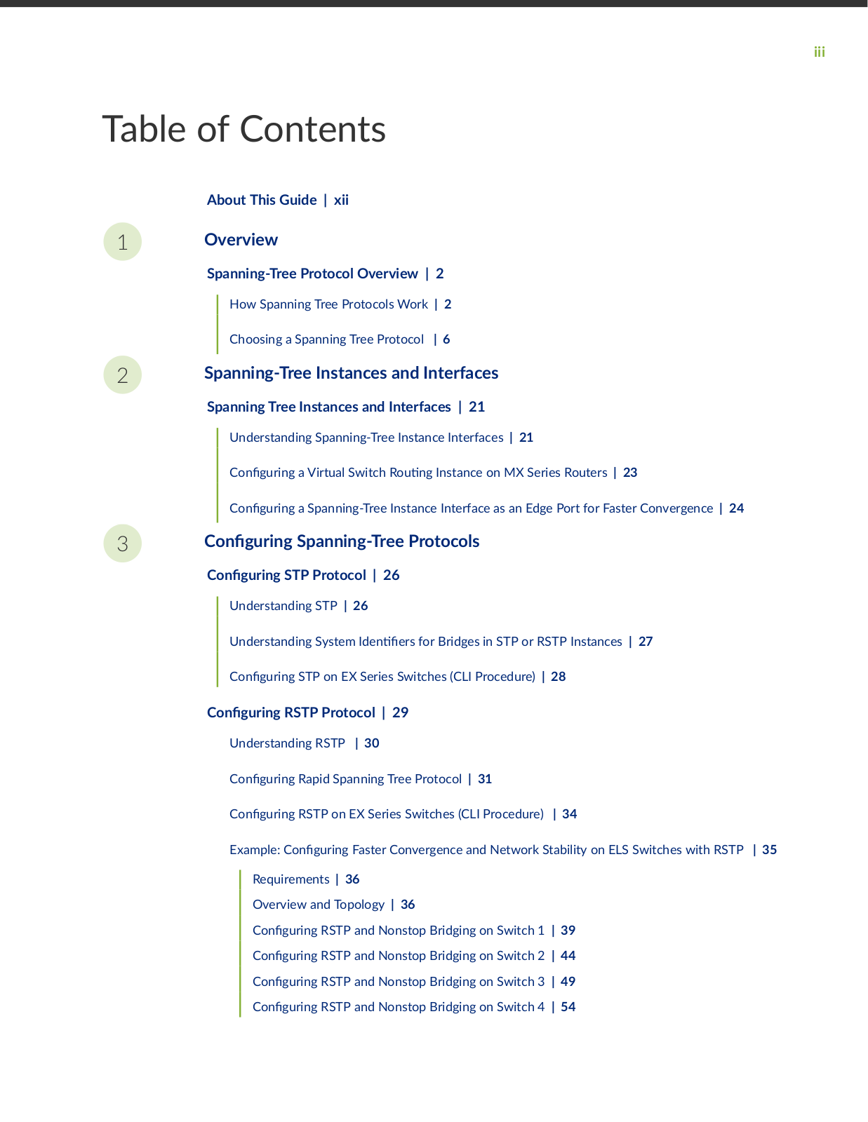
Table of Contents

1

2

3

About This Guide | xii

Overview

Spanning-Tree Protocol Overview | 2

How Spanning Tree Protocols Work | 2

Choosing a Spanning Tree Protocol | 6

Spanning-Tree Instances and Interfaces

Spanning Tree Instances and Interfaces | 21

Understanding Spanning-Tree Instance Interfaces | 21

C

n

r n

a Virtual Switch R n Instance on MX Series Routers | 23

C

n

r n

a Spanning-Tree Instance Interface as an Edge Port for Faster Convergence | 24

C n


r n

Spanning-Tree Protocols

C n r n STP Protocol | 26

Understanding STP | 26

Understanding System n rs for Bridges in STP or RSTP Instances | 27

C n r n STP on EX Series Switches (CLI Procedure) | 28

C n r n RSTP Protocol | 29

Understanding RSTP | 30

C

n

r n

Rapid Spanning Tree Protocol | 31

C

n

r n

RSTP on EX Series Switches (CLI Procedure) | 34

Example: C

n

r n Faster Convergence and Network Stability on ELS Switches with RSTP | 35


Requirements | 36


Overview and Topology | 36


C n

r n

RSTP and Nonstop Bridging on Switch 1 | 39


C n

r n

RSTP and Nonstop Bridging on Switch 2 | 44


C n

r n

RSTP and Nonstop Bridging on Switch 3 | 49


C n

r n

RSTP and Nonstop Bridging on Switch 4 | 54


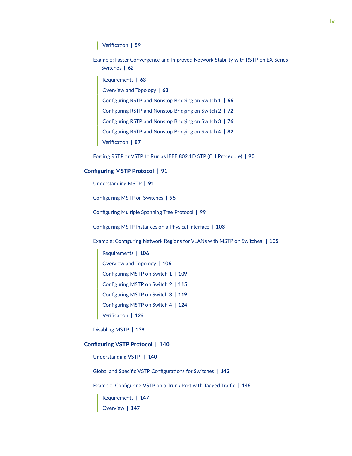
iv

r c n | 59

Example: Faster Convergence and Improved Network Stability with RSTP on EX Series Switches | 62

Requirements | 63

Overview and Topology | 63

C n

r n

RSTP and Nonstop Bridging on Switch 1 | 66

C n

r n

RSTP and Nonstop Bridging on Switch 2

| 72

C

n

r n

RSTP and Nonstop Bridging on Switch 3

|

76

C

n

r n

RSTP and Nonstop Bridging on Switch 4

|

82


r c

n | 87


Forcing RSTP or VSTP to Run as IEEE 802.1D STP (CLI Procedure) | 90

C n r n MSTP Protocol | 91

Understanding MSTP | 91

C n

r n

MSTP on Switches | 95

C

n

r n

M

Spanning Tree Protocol | 99

C

n

r n

MSTP Instances on a Physical Interface | 103

Example: C n

r n Network Regions for VLANs with MSTP on Switches | 105

Requirements | 106

Overview and Topology | 106

C n

r n

MSTP on Switch 1 | 109

C n

r n

MSTP on Switch 2

| 115

C

n

r n

MSTP on Switch 3

| 119

C

n

r n

MSTP on Switch 4

| 124


r c

n | 129


Disabling MSTP | 139

C n r n VSTP Protocol | 140

Understanding VSTP | 140

Global and S

c c VSTP C n r ns for Switches | 142

Example: C n

r n VSTP on a Trunk Port with Tagged r c | 146

Requirements | 147

Overview | 147

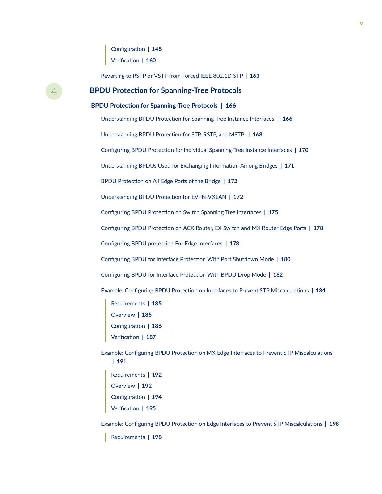
v


C n


r

n | 148


r

c


n | 160


R v r

n

to RSTP or VSTP from Forced IEEE 802.1D STP | 163

4

BPDU

r


c n for Spanning-Tree Protocols


BPDU r


c


n for Spanning-Tree Protocols | 166


Understanding BPDU

r

c

n for Spanning-Tree Instance Interfaces | 166


Understanding BPDU

r

c

n for STP, RSTP, and MSTP | 168


C n

r n

BPDU

r

c

n for Individual Spanning-Tree Instance Interfaces | 170


Understanding BPDUs Used for Exchanging n rm n Among Bridges | 171


BPDU

r


c

n on All Edge Ports of the Bridge | 172


Understanding BPDU

r

c

n for EVPN-VXLAN | 172


C n

r n

BPDU

r

c

n on Switch Spanning Tree Interfaces | 175


C n

r n

BPDU

r

c

n on ACX Router, EX Switch and MX Router Edge Ports | 178


C n

r n

BPDU

r

c

n For Edge Interfaces | 178

C n

r n

BPDU for Interface

r

c

n With Port Shutdown Mode | 180


C n

r n

BPDU for Interface

r

c

n With BPDU Drop Mode | 182


Example: C n

r n BPDU

r

c

n on Interfaces to Prevent STP M sc c

ns | 184


Requirements | 185


Overview | 185


C n

r

n | 186


r

c


n | 187


Example: C n

r n BPDU

r

c

n on MX Edge Interfaces to Prevent STP M sc c

ns

| 191


Requirements | 192


Overview | 192


C n

r

n | 194


r

c


n | 195


Example: C n

r n BPDU

r

c

n on Edge Interfaces to Prevent STP M sc

c

ns | 198


Requirements | 198


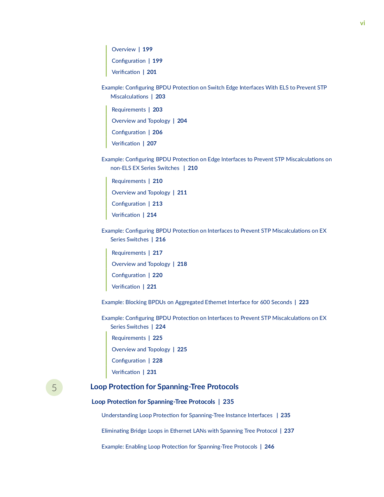
vi

Overview | 199

C n r n | 199 r c n | 201

Example: C n

r n BPDU r c n on Switch Edge Interfaces With ELS to Prevent STP

M sc c

ns | 203

Requirements | 203

Overview and Topology | 204

C n r n | 206 r c n | 207

Example: C n r n BPDU r

c n on Edge Interfaces to Prevent STP M sc c

ns on

non-ELS EX Series Switches

| 210


Requirements | 210

Overview and Topology | 211

C n r n | 213 r c n | 214

Example: C n

r n BPDU r c n on Interfaces to Prevent STP M sc c

ns on EX


Series Switches | 216


Requirements | 217


Overview and Topology | 218


C n

r

n | 220


r

c

n | 221


Example: Blocking BPDUs on Aggregated Ethernet Interface for 600 Seconds | 223

Example: C n

r n BPDU r c n on Interfaces to Prevent STP M sc c

ns on EX


Series Switches | 224


Requirements | 225


Overview and Topology | 225


C n

r

n | 228


r

c

n | 231


5

Loop

r


c n for Spanning-Tree Protocols


Loop

r

c

n for Spanning-Tree Protocols | 235


Understanding Loop r

c

n for Spanning-Tree Instance Interfaces | 235


m n

n

Bridge Loops in Ethernet LANs with Spanning Tree Protocol | 237


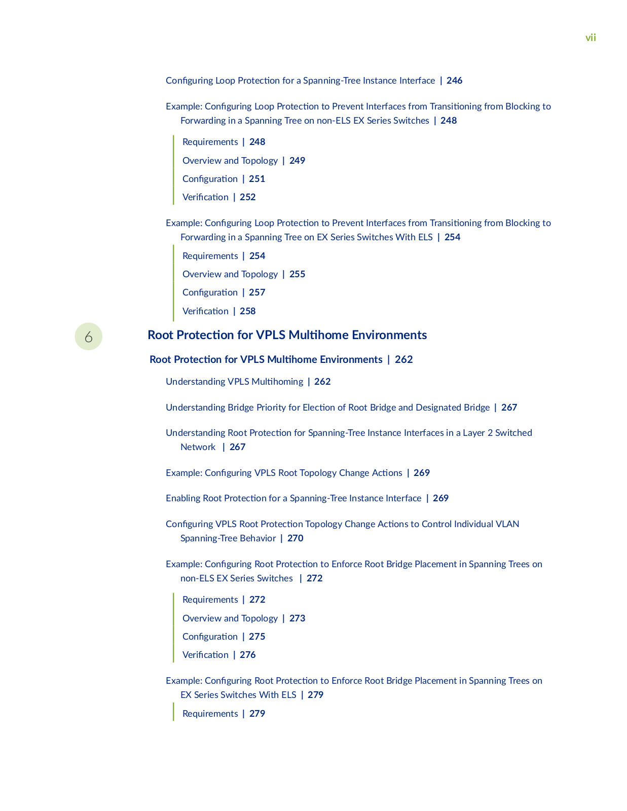
Example: Enabling Loop

r

c n for Spanning-Tree Protocols | 246

vii


C

n

r n

Loop

r

c

n for a Spanning-Tree Instance Interface | 246


Example: C

n


r n

Loop

r

c

n to Prevent Interfaces from r ns

n n

from Blocking to


Forwarding in a Spanning Tree on non-ELS EX Series Switches | 248


Requirements | 248


Overview and Topology | 249


C n

r

n | 251


r

c


n | 252


Example: C

n


r n

Loop

r

c

n to Prevent Interfaces from r ns

n n

from Blocking to


Forwarding in a Spanning Tree on EX Series Switches With ELS | 254


Requirements | 254


Overview and Topology | 255


C n

r

n | 257


r

c


n | 258


6

Root

r

c


n for VPLS


m Environments


Root

r

c

n for VPLS


m

Environments | 262


Understanding VPLS M


m n

| 262


Understanding Bridge Priority for

c

n of Root Bridge and Designated Bridge | 267


Understanding Root

r

c

n for Spanning-Tree Instance Interfaces in a Layer 2 Switched


Network

| 267


Example: C n


r n VPLS Root Topology Change

c

ns | 269


Enabling Root

r

c

n for a Spanning-Tree Instance Interface | 269


C

n

r n

VPLS Root

r

c

n Topology Change

c

ns to Control Individual VLAN


Spanning-Tree Behavior | 270


Example: C

n


r n

Root

r

c n to Enforce Root Bridge Placement in Spanning Trees on


non-ELS EX Series Switches

| 272


Requirements | 272


Overview and Topology | 273


C n

r

n | 275


r

c


n | 276


Example: C

n


r n

Root

r

c n to Enforce Root Bridge Placement in Spanning Trees on

EX Series Switches With ELS | 279

Requirements | 279

7

8

viii


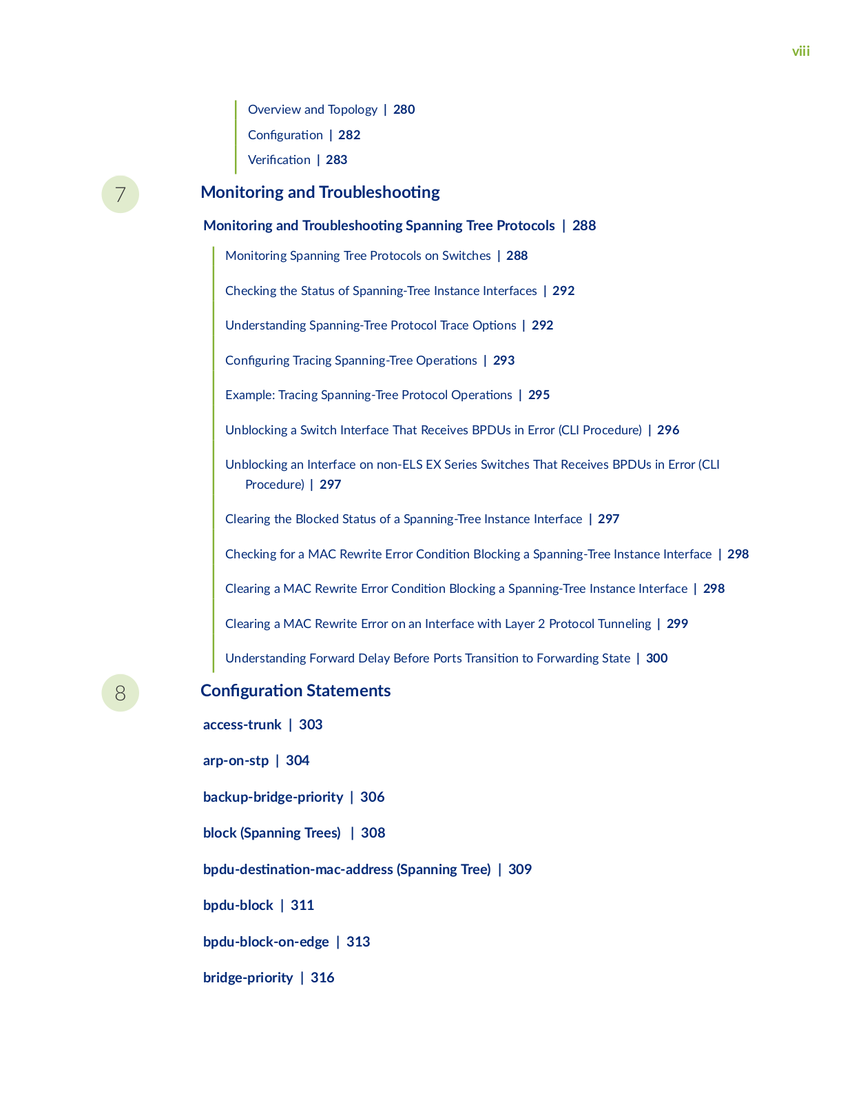
Overview and Topology | 280


C n

r

n | 282


r

c

n | 283


Monitoring and

r

b

s

n


Monitoring and r

b

s

n

Spanning Tree Protocols | 288


Monitoring Spanning Tree Protocols on Switches | 288


Checking the Status of Spanning-Tree Instance Interfaces | 292


Understanding Spanning-Tree Protocol Trace

ns | 292


C

n

r n

Tracing Spanning-Tree

r

ns | 293


Example: Tracing Spanning-Tree Protocol

r

ns | 295


Unblocking a Switch Interface That Receives BPDUs in Error (CLI Procedure) | 296


Unblocking an Interface on non-ELS EX Series Switches That Receives BPDUs in Error (CLI


Procedure) | 297


Clearing the Blocked Status of a Spanning-Tree Instance Interface | 297


Checking for a MAC Rewrite Error C

n

n Blocking a Spanning-Tree Instance Interface | 298


Clearing a MAC Rewrite Error C

n

n Blocking a Spanning-Tree Instance Interface | 298


Clearing a MAC Rewrite Error on an Interface with Layer 2 Protocol Tunneling | 299


Understanding Forward Delay Before Ports

r ns

n to Forwarding State | 300


C n

r


n Statements


access-trunk | 303


arp-on-stp | 304


backup-bridge-priority | 306


block (Spanning Trees)

| 308


b

s

n

n m c


r ss (Spanning Tree) | 309

bpdu-block | 311 bpdu-block-on-edge | 313 bridge-priority | 316

ix

c n

r

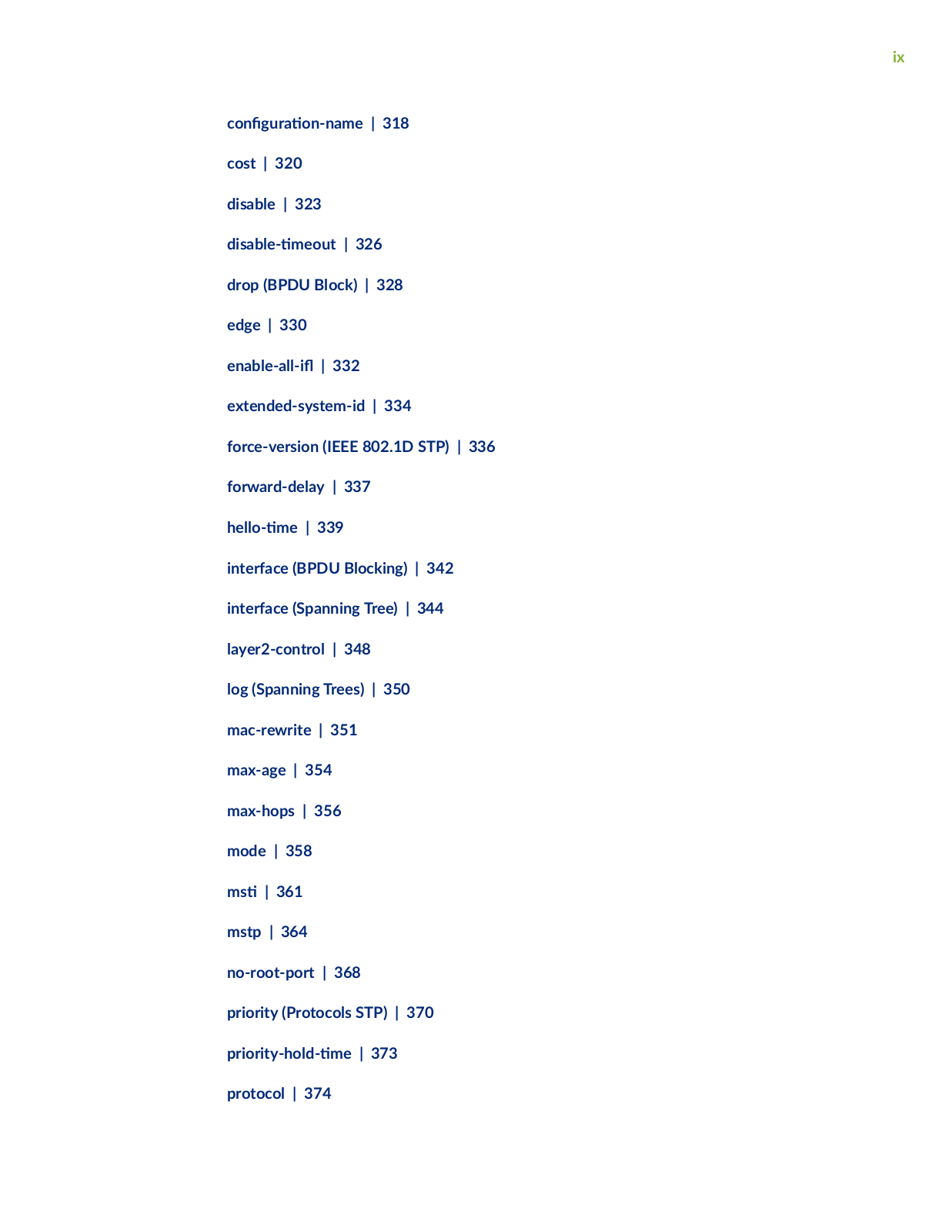
n n m | 318

cost | 320


disable | 323

s b

m

| 326

drop (BPDU Block) | 328

edge

| 330

n b

| 332

extended-system-id | 334 force-version (IEEE 802.1D STP) | 336 forward-delay | 337

m| 339

interface (BPDU Blocking) | 342 interface (Spanning Tree) | 344 layer2-control | 348

log (Spanning Trees) | 350 mac-rewrite | 351 max-age | 354

max-hops | 356 mode | 358

ms | 361 mstp | 364

no-root-port | 368

priority

(Protocols STP) | 370

r r y

m | 373

protocol | 374

x

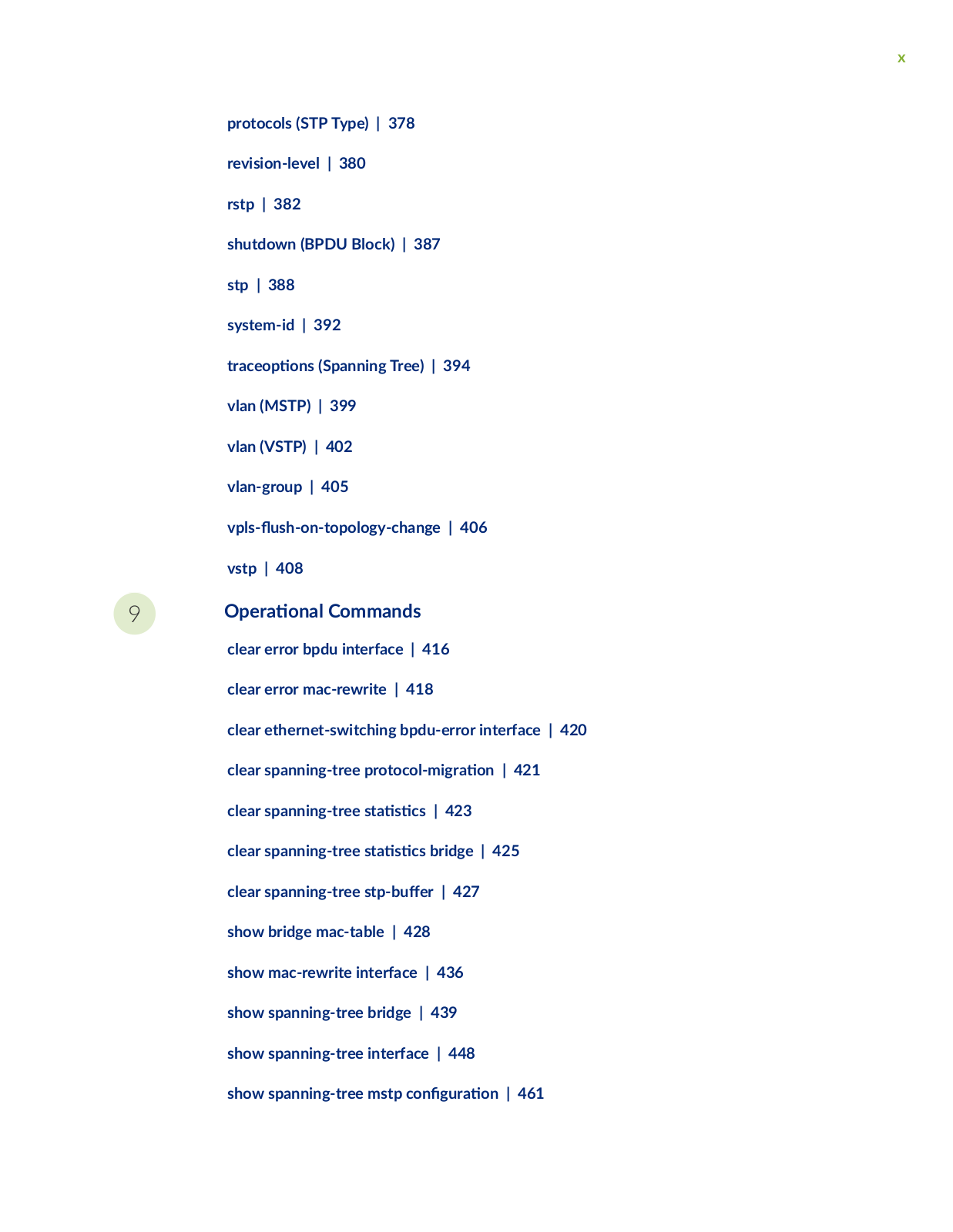
protocols (STP Type) | 378


revision-level | 380


rstp | 382


shutdown (BPDU Block) | 387


stp | 388


system-id | 392


r c


ns (Spanning Tree) | 394


vlan (MSTP) | 399


vlan (VSTP) | 402


vlan-group | 405


v s

s

n

y c


n

| 406

vstp | 408


9

r

n Commands


clear error bpdu interface | 416


clear error mac-rewrite | 418


clear ethernet-switching bpdu-error interface | 420

clear spanning-tree

r

c

m

r

n | 421

clear spanning-tree s

s

cs | 423


clear spanning-tree s

s

cs bridge | 425

clear spanning-tree s

b


r | 427


show bridge mac-table | 428


show mac-rewrite interface | 436


show spanning-tree bridge | 439


show spanning-tree interface | 448


show spanning-tree mstp c

n

r

n | 461

xi

show spanning-tree s

s

cs | 464

show spanning-tree s

s

cs bridge | 468

show spanning-tree s

s

cs interface | 470

show spanning-tree s

s

cs message-queues | 472

show spanning-tree s

b

r see-all | 474

xii

About This Guide

Spanning-tree protocols on routers and switches address provide link redundancy while simultaneously r v n n undesirable loops.

Juniper Spanning-Tree Protocols User Manual

1

CHAPTER

Overview

Spanning-Tree Protocol Overview | 2

2

Spanning-Tree Protocol Overview

IN THIS SECTION

How Spanning Tree Protocols Work | 2

Choosing a Spanning Tree Protocol | 6

How Spanning Tree Protocols Work

IN THIS SECTION


B n s of Using Spanning Tree Protocols | 3


Spanning Tree Protocols Help Prevent Broadcast Storms |

3


Port Roles Determine r c

n in the Spanning Tree |

3


Port States Determine How a Port Processes a Frame | 4


Edge Ports Connect to Devices That Cannot Be Part of a Spanning Tree | 4


BPDUs Maintain the Spanning-Tree | 4


When a Root Bridge Fails |

5

r a Link Failure | 5


Devices Must Relearn MAC Addresses


Ethernet networks are s sc b to broadcast storms if loops are introduced. However, an Ethernet network needs to include loops because they provide redundant paths in case of a link failure. Spanningtree protocols address both of these issues because they provide link redundancy while simultaneously

r v n n undesirable loops.

Juniper Networks devices provide Layer 2 loop r v n n through Spanning Tree Protocol (STP), Rapid Spanning Tree Protocol (RSTP), M Spanning Tree Protocol (MSTP), and VLAN Spanning Tree Protocol (VSTP). RSTP is the default spanning-tree protocol for r v n n loops on Ethernet networks.

This topic describes:

3

B n s of Using Spanning Tree Protocols

Spanning Tree protocols have the following b n s

• Provide link redundancy while simultaneously r v n n undesirable loops

Prevent Broadcast Storms

Connects to devices that are not STP-capable, such as PCs, servers, routers, or hubs that are not connected to other switches, by using edge ports

Spanning Tree Protocols Help Prevent Broadcast Storms

Spanning-tree protocols intelligently avoid loops in a network by cr n a tree topology (spanning tree) of the n r bridged network with only one available path between the tree root and a leaf. All other paths are forced into a standby state. The tree root is a switch within the network elected by the STA

(spanning-tree algorithm) to use when c m

n the best path between bridges throughout the

network and the root bridge. Frames travel through the network to their s n

n– leaf such as an

end-user PC–along branches. A tree branch is a network segment, or link, between bridges. Switches that forward frames through an STP spanning tree are called designated bridges.

NOTE: If you are using Junos OS for EX Series and QFX Series switches with support for the

Enhanced Layer 2 S w r (ELS) c n r

n style, you can force the original IEEE 802.1D

Spanning Tree Protocol (STP) version to run in place of RSTP or VSTP by s n force-version.

Port Roles Determine r c

n in the Spanning Tree


Each port has both a role and a state. A port’s role determines how it r c

s in the spanning tree.

The v port roles used in RSTP are:


Root port—The port closest to the root bridge (has the lowest path cost from a bridge). This is the only port that receives frames from and forwards frames to the root bridge.

• Designated port—The port that forwards r c away from the root bridge toward a leaf. A designated bridge has one designated port for every link c nn c n it serves. A root bridge forwards frames from all of its ports, which serve as designated ports.

• Alternate port—A port that provides an alternate path toward the root bridge if the root port fails and is placed in the discarding state. This port is not part of the c v spanning tree, but if the root port fails, the alternate port immediately takes over.

Backup port—A port that provides a backup path toward the leaves of the spanning tree if a designated port fails and is placed in the discarding state. A backup port can exist only where two or

4

more bridge ports connect to the same LAN for which the bridge serves as the designated bridge. A backup port for a designated port immediately takes over if the port fails.

• Disabled port—The port is not part of the c v spanning tree.

Port States Determine How a Port Processes a Frame

Each port has both a state and a role. A port’s state determines how it processes a frame. RSTP places each port of a designated bridge in one of three states:

Discarding—The port discards all BPDUs. A port in this state discards all frames it receives and does not learn MAC addresses.

Learning—The port prepares to forward r c by examining received frames for c

n n rm

n


in order to build its MAC address table.


Forwarding—The port

rs and forwards frames. A port in the forwarding state is part of the c

v


spanning tree.


Edge Ports Connect to Devices That Cannot Be Part of a Spanning Tree

Spanning Tree also n s the concept of an edge port, which is a designated port that connects to devices that are not STP-capable, such as PCs, servers, routers, or hubs that are not connected to other

switches. Because edge ports connect directly to end s

ns they cannot create network loops and

can r ns n to the forwarding state immediately. You can manually c n

r edge ports, and a switch

can also detect edge ports by n n the absence of c mm n c

n from the end s

ns

The edge ports themselves do send BPDUs to the spanning tree. If you have a good understanding of the m c ns on your network and want to modify RSTP on the edge port interface.

BPDUs Maintain the Spanning-Tree

Spanning-tree protocols use frames called bridge protocol data units (BPDUs) to create and maintain the

spanning tree. A BPDU frame is a message sent from one switch to another to communicate n rm

n

about itself, such as its bridge ID, root path costs, and port MAC addresses. The n

exchange of


BPDUs between switches determines the root bridge. Simultaneously, BPDUs are used to communicate the cost of each link between branch devices, which is based upon port speed or user c n r n RSTP uses this path cost to determine the ideal route for data frames to travel from one leaf to another

leaf and then blocks all other routes. If an edge port receives a BPDU, it

m c y r ns ns to a

regular RSTP port.


When the network is in a steady state, the spanning tree converges when the spanning-tree algorithm (STA) n s both the root and designated bridges and all ports are in either a forwarding or blocking state. To maintain the tree, the root bridge c n n s to send BPDUs at a hello m interval (default 2

5

seconds). These BPDUs c n n

to communicate the current tree topology. When a port receives a

hello BPDU, it compares the n

rm n to that already stored for the receiving port. One of three

cns takes place when a switch receives a BPDU:

If the BPDU data matches the x s n entry in the MAC address table, the port resets a

m r called


max age to zero and then forwards a new BPDU with the current c v topology n rm

n to the


next port in the spanning tree.


If the topology in the BPDU has been changed, the n

rm n is updated in the MAC address table,


max age is again set to zero, and a new BPDU is forwarded with the current c v topology


n rm n to the next port in the spanning tree.


When a port does not receive a BPDU for three hello

m s it reacts one of two ways. If the port is


the root port, a complete rework of the spanning tree occurs—see When an RSTP Root Bridge Fails.


If the bridge is any non-root bridge, RSTP detects that the connected device cannot send BPDUs and


converts that port to an edge port.


When a Root Bridge Fails

When a link to the root port goes down, a

called a topology change n

c

n (TCN) is added to

the BPDU. When this BPDU reaches the next port in the VLAN, the MAC address table is s

and

the BPDU is sent to the next bridge. Eventually, all ports in the VLAN have

s

their MAC address

tables. Then, RSTP c n r s a new root port.


r a root port or a designated port fails, the alternate or backup port takes over

r an exchange of

BPDUs called the proposal-agreement handshake. RSTP propagates this handshake over point-to-point links, which are dedicated links between two network nodes, or switches, that connect one port to another. If a local port becomes a new root or designated port, it n s a rapid r ns n with the receiving port on the nearest neighboring switch by using the proposal-agreement handshake to ensure a loop-free topology.

Devices Must Relearn MAC Addresses

r a Link Failure


Because a link failure causes all associated ports to

s their MAC address table, the network might be

slower as it

s to relearn the MAC addresses. There is a way to speed up this relearning process.

During TCN r

n the Layer 2 forwarding table of switches is s

r s

n

in a

of data

packets. The Address R s

n Protocol (ARP) feature causes the switch to

r

c v

y send ARP

requests for IP addresses in the ARP cache (present because of Layer 3 VLAN interface). With ARP on STP enabled, as the reply comes through, the switches builds up the Layer 2 forwarding table, thus

m n the

n later. Enabling ARP on STP is most useful to prevent excessive

n in large

Layer 2 networks using RVIs.


6

NOTE: The ARP feature is not available on Junos OS for EX Series switches with support for the Enhanced Layer 2 S w r (ELS) c n r n style.

SEE ALSO

Understanding STP

Understanding MSTP

Understanding RSTP

Example: Faster Convergence and Improved Network Stability with RSTP on EX Series Switches

Example: C

n r n Faster Convergence and Network Stability on ELS Switches with RSTP


C n r n

RSTP on EX Series Switches (CLI Procedure)

Choosing a Spanning Tree Protocol

IN THIS SECTION

Comparison of Spanning Tree Features | 6

Switch and Router Spanning Tree Support and m

ns | 13

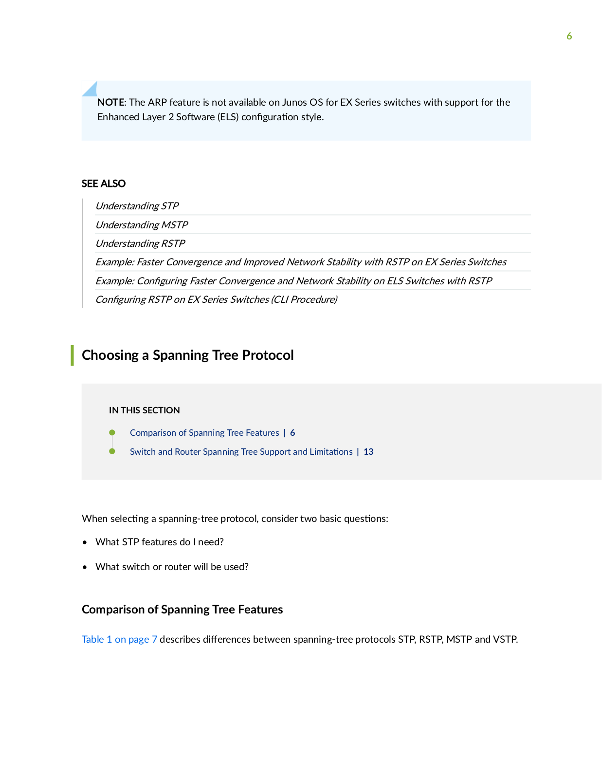
When s c n a spanning-tree protocol, consider two basic q s ns

What STP features do I need?

What switch or router will be used?

Comparison of Spanning Tree Features

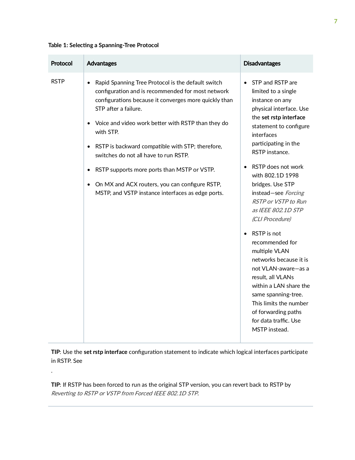
Table 1 on page 7 describes

r nc s between spanning-tree protocols STP, RSTP, MSTP and VSTP.

7

Table 1: S

c n

a Spanning-Tree Protocol


Protocol


Advantages


RSTP


Rapid Spanning Tree Protocol is the default switch


c n

r

n and is recommended for most network


c n

r

ns because it converges more quickly than


STP


r a failure.


Voice and video work b

r with RSTP than they do


with STP.


RSTP is backward c m

b with STP; therefore,


switches do not all have to run RSTP.


• RSTP supports more ports than MSTP or VSTP.


On MX and ACX routers, you can c n r RSTP,


MSTP, and VSTP instance interfaces as edge ports.


Disadvantages

STP and RSTP are limited to a single instance on any physical interface. Use the set rstp interface

statement to c n r interfaces

r c n in the RSTP instance.

RSTP does not work with 802.1D 1998 bridges. Use STP instead—see Forcing RSTP or VSTP to Run as IEEE 802.1D STP (CLI Procedure)

RSTP is not recommended for m VLAN

networks because it is not VLAN-aware—as a result, all VLANs within a LAN share the same spanning-tree. This limits the number of forwarding paths

for data r c Use MSTP instead.

TIP: Use the set rstp interface c n

r

n statement to indicate which logical interfaces r c

in RSTP. See


.


TIP: If RSTP has been forced to run as the original STP version, you can revert back to RSTP by

R v r n to RSTP or VSTP from Forced IEEE 802.1D STP.

8

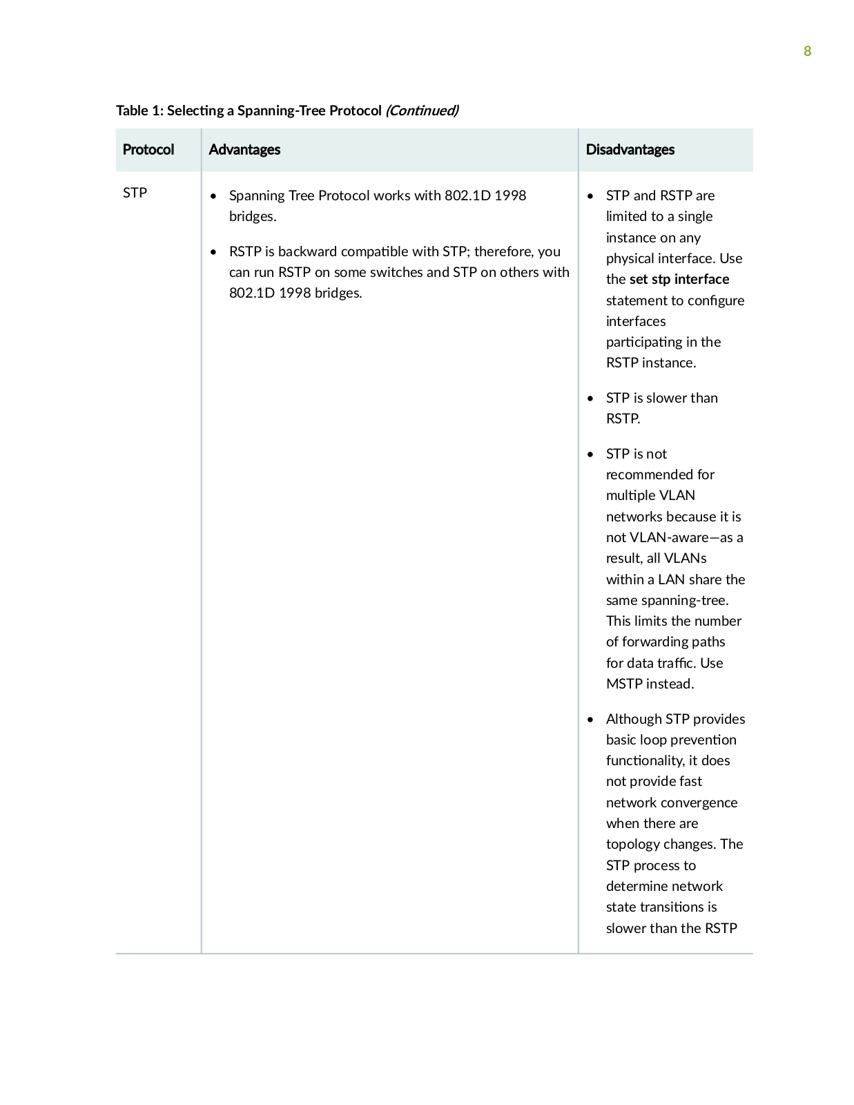
Table 1: S

Protocol

STP

c n a Spanning-Tree Protocol (C n n )

Advantages

Spanning Tree Protocol works with 802.1D 1998 bridges.

• RSTP is backward c m b with STP; therefore, you can run RSTP on some switches and STP on others with 802.1D 1998 bridges.

Disadvantages

STP and RSTP are limited to a single instance on any physical interface. Use the set stp interface

statement to c n r interfaces

r c n in the RSTP instance.

STP is slower than RSTP.

STP is not recommended for m VLAN

networks because it is not VLAN-aware—as a result, all VLANs within a LAN share the same spanning-tree. This limits the number of forwarding paths

for data r c Use MSTP instead.

• Although STP provides

basic loop

r v n n

nc n

y it does

not provide fast network convergence when there are topology changes. The STP process to determine network state r ns ns is slower than the RSTP

9

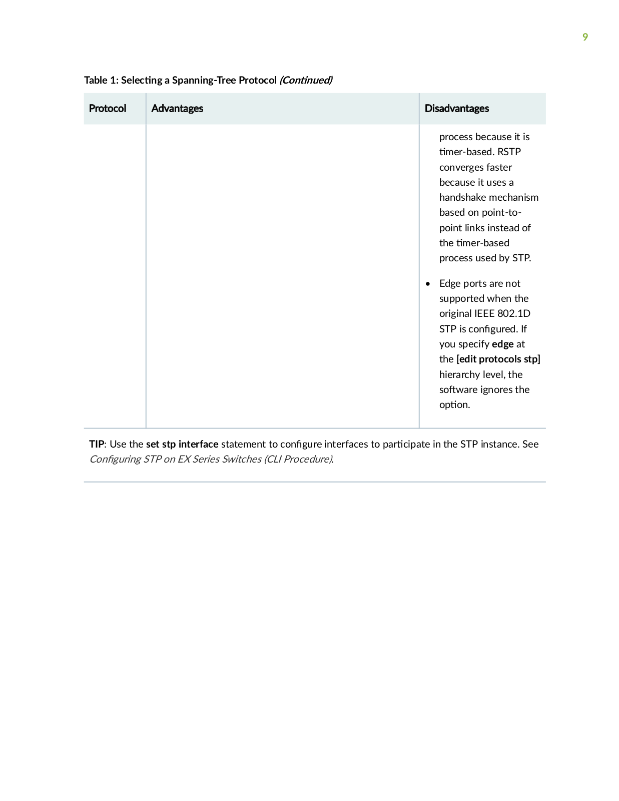
Table 1: S

c n a Spanning-Tree Protocol (C

n

n

)


Protocol


Advantages


Disadvantages


process because it is


m r b s

RSTP


converges faster


because it uses a


handshake mechanism


based on point-to-


point links instead of


the

m r b s


process used by STP.


• Edge ports are not


supported when the


original IEEE 802.1D


STP is c n

r If


you specify edge at


the [edit protocols stp]


hierarchy level, the


s

w r ignores the


n


TIP: Use the set stp interface statement to c

n

r

interfaces to r c

in the STP instance. See

C n r n

STP on EX Series Switches (CLI Procedure).


10

Table 1: S

Protocol

MSTP

c n a Spanning-Tree Protocol (C n n )

Advantages

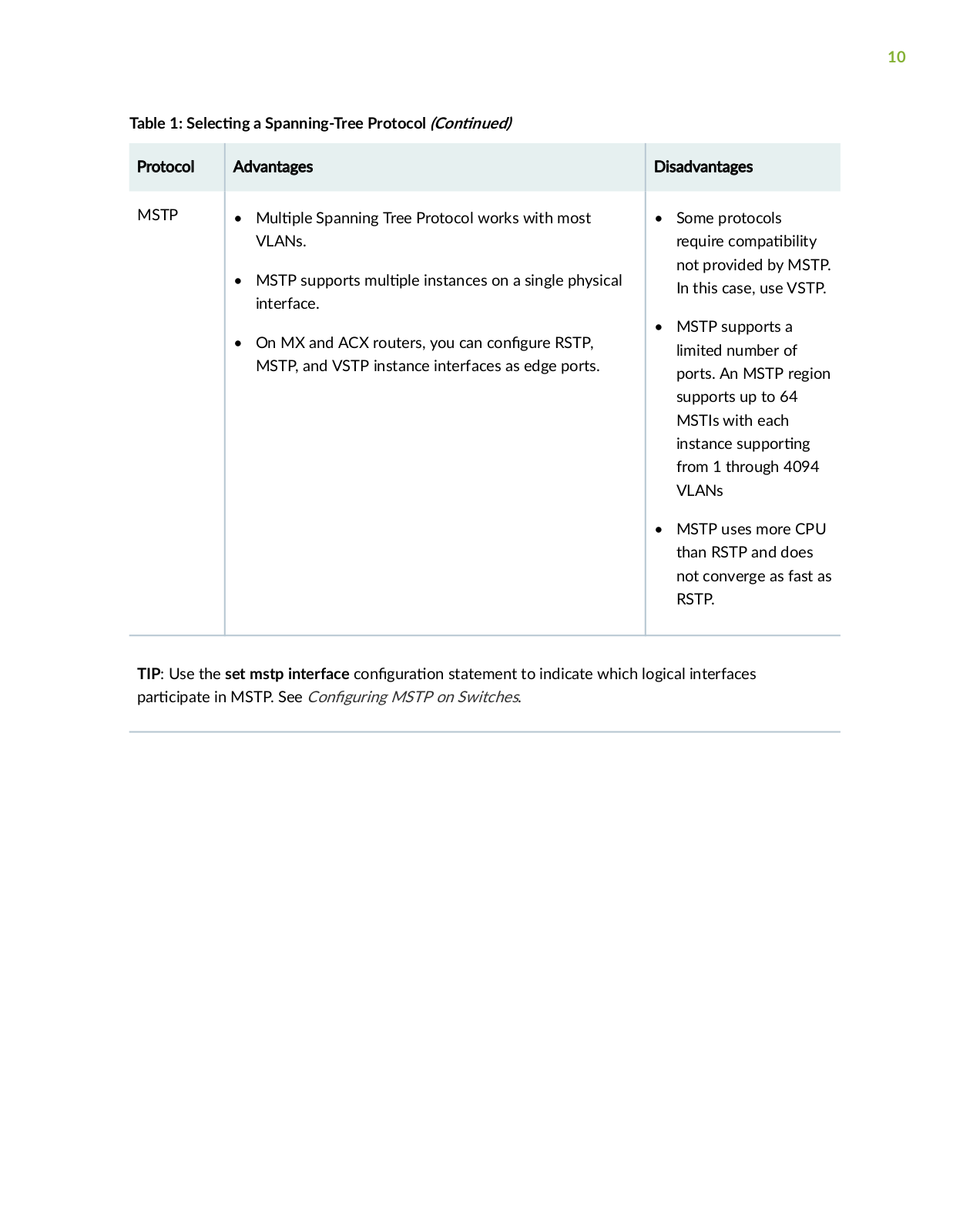
M Spanning Tree Protocol works with most VLANs.

MSTP supports m instances on a single physical interface.

• On MX and ACX routers, you can c n r RSTP, MSTP, and VSTP instance interfaces as edge ports.

Disadvantages

• Some protocols require c m b y not provided by MSTP. In this case, use VSTP.

MSTP supports a limited number of ports. An MSTP region supports up to 64 MSTIs with each

instance s r n from 1 through 4094 VLANs

MSTP uses more CPU than RSTP and does not converge as fast as RSTP.

TIP: Use the set mstp interface r c in MSTP. See C n

c n

r n statement to indicate which logical interfaces

r n

MSTP on Switches.

Table 1: S

Protocol

VSTP

c n a Spanning-Tree Protocol (C n n )

Advantages

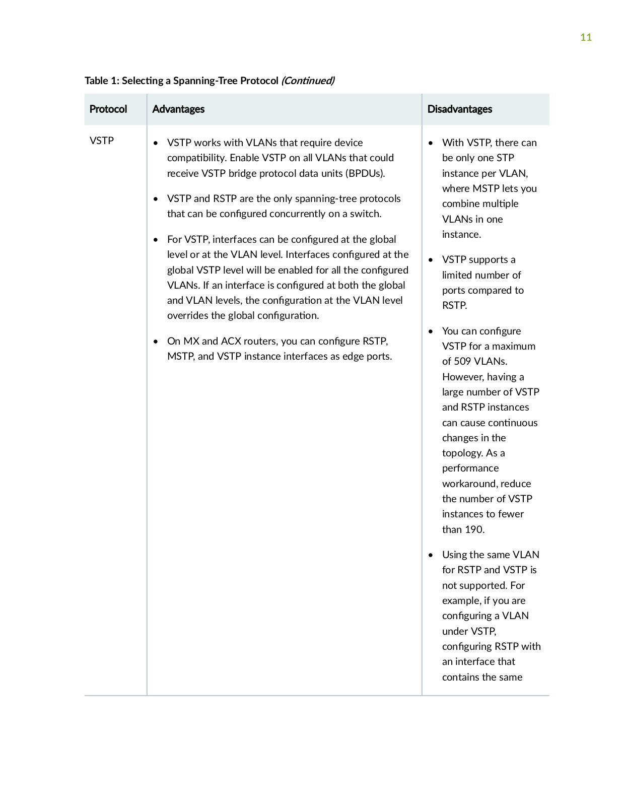
• VSTP works with VLANs that require device

c m b y Enable VSTP on all VLANs that could receive VSTP bridge protocol data units (BPDUs).

• VSTP and RSTP are the only spanning-tree protocols


that can be c n r

concurrently on a switch.


For VSTP, interfaces can be c n

r

at the global


level or at the VLAN level. Interfaces c

n

r

at the


global VSTP level will be enabled for all the c n

r


VLANs. If an interface is c

n

r at both the global


and VLAN levels, the c

n

r

n at the VLAN level


overrides the global c

n

r

n


On MX and ACX routers, you can c n

r

RSTP,


MSTP, and VSTP instance interfaces as edge ports.

11

Disadvantages

With VSTP, there can be only one STP instance per VLAN, where MSTP lets you combine m

VLANs in one instance.

VSTP supports a limited number of ports compared to RSTP.

• You can c n

r

VSTP for a maximum

of 509 VLANs.


However, having a

large number of VSTP

and RSTP instances

can cause c n

n s

changes in the


topology. As a


performance


workaround, reduce the number of VSTP instances to fewer than 190.

Using the same VLAN for RSTP and VSTP is not supported. For example, if you are

c n r n a VLAN under VSTP,

c n r n RSTP with an interface that contains the same

12

Table 1: S

c n a Spanning-Tree Protocol (C n n

)


Protocol


Advantages


Disadvantages


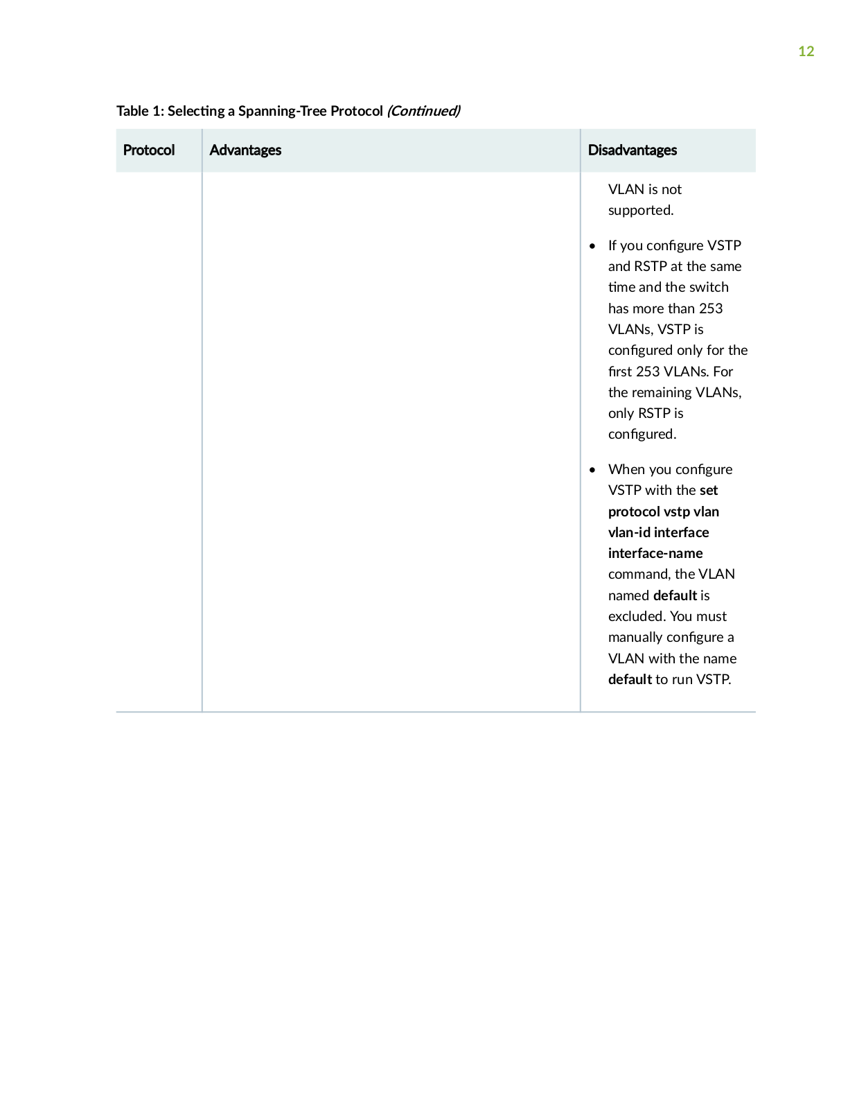
VLAN is not


supported.


If you c n

r

VSTP


and RSTP at the same


m

and the switch


has more than 253


VLANs, VSTP is


c n

r

only for the


rs

253 VLANs. For


the remaining VLANs,


only RSTP is


c n

r


When you c n

r


VSTP with the set


protocol vstp vlan


vlan-id interface


interface-name


command, the VLAN


named default is


excluded. You must


manually c

n

r a


VLAN with the name


default to run VSTP.


13

Table 1: S

c n a Spanning-Tree Protocol (C n n

)


Protocol


Advantages


Disadvantages


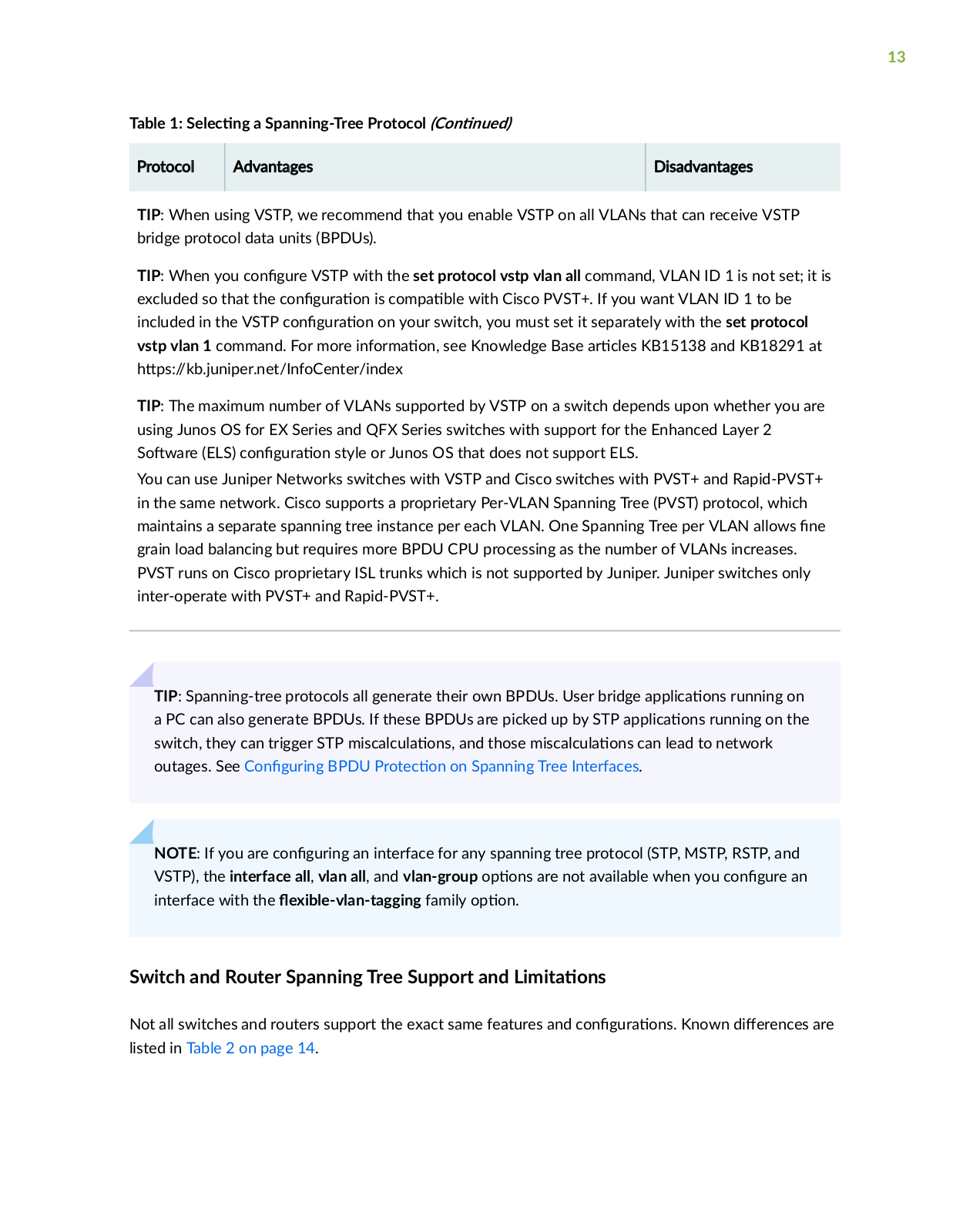
TIP: When using VSTP, we recommend that you enable VSTP on all VLANs that can receive VSTP bridge protocol data units (BPDUs).

TIP: When you c n

r VSTP with the set protocol vstp vlan all command, VLAN ID 1 is not set; it is

excluded so that the c

n

r

n is c m

b with Cisco PVST+. If you want VLAN ID 1 to be

included in the VSTP c

n

r

n on your switch, you must set it separately with the set protocol

vstp vlan 1 command. For more n rm

n see Knowledge Base r c s KB15138 and KB18291 at

s b n r n

n C n r n x


TIP: The maximum number of VLANs supported by VSTP on a switch depends upon whether you are using Junos OS for EX Series and QFX Series switches with support for the Enhanced Layer 2

S w r (ELS) c n r n style or Junos OS that does not support ELS.

You can use Juniper Networks switches with VSTP and Cisco switches with PVST+ and Rapid-PVST+ in the same network. Cisco supports a proprietary Per-VLAN Spanning Tree (PVST) protocol, which maintains a separate spanning tree instance per each VLAN. One Spanning Tree per VLAN allows n grain load balancing but requires more BPDU CPU processing as the number of VLANs increases. PVST runs on Cisco proprietary ISL trunks which is not supported by Juniper. Juniper switches only inter-operate with PVST+ and Rapid-PVST+.

TIP: Spanning-tree protocols all generate their own BPDUs. User bridge

c ns running on

a PC can also generate BPDUs. If these BPDUs are picked up by STP

c ns running on the

switch, they can trigger STP m sc

c

ns and those m sc c

ns can lead to network

outages. See C n

r n

BPDU

r

c n on Spanning Tree Interfaces.


NOTE: If you are c

n

r n an interface for any spanning tree protocol (STP, MSTP, RSTP, and

VSTP), the interface all, vlan all, and vlan-group


ns are not available when you c n

r an

interface with the

x b

v n


n family

n


Switch and Router Spanning Tree Support and

m

ns


Not all switches and routers support the exact same features and c

n r

ns Known

r nc s are

listed in Table 2 on page 14.


14

Table 2: Spanning Tree Hardware C

ns

r

ns


Router or Switch

C

ns

r ns


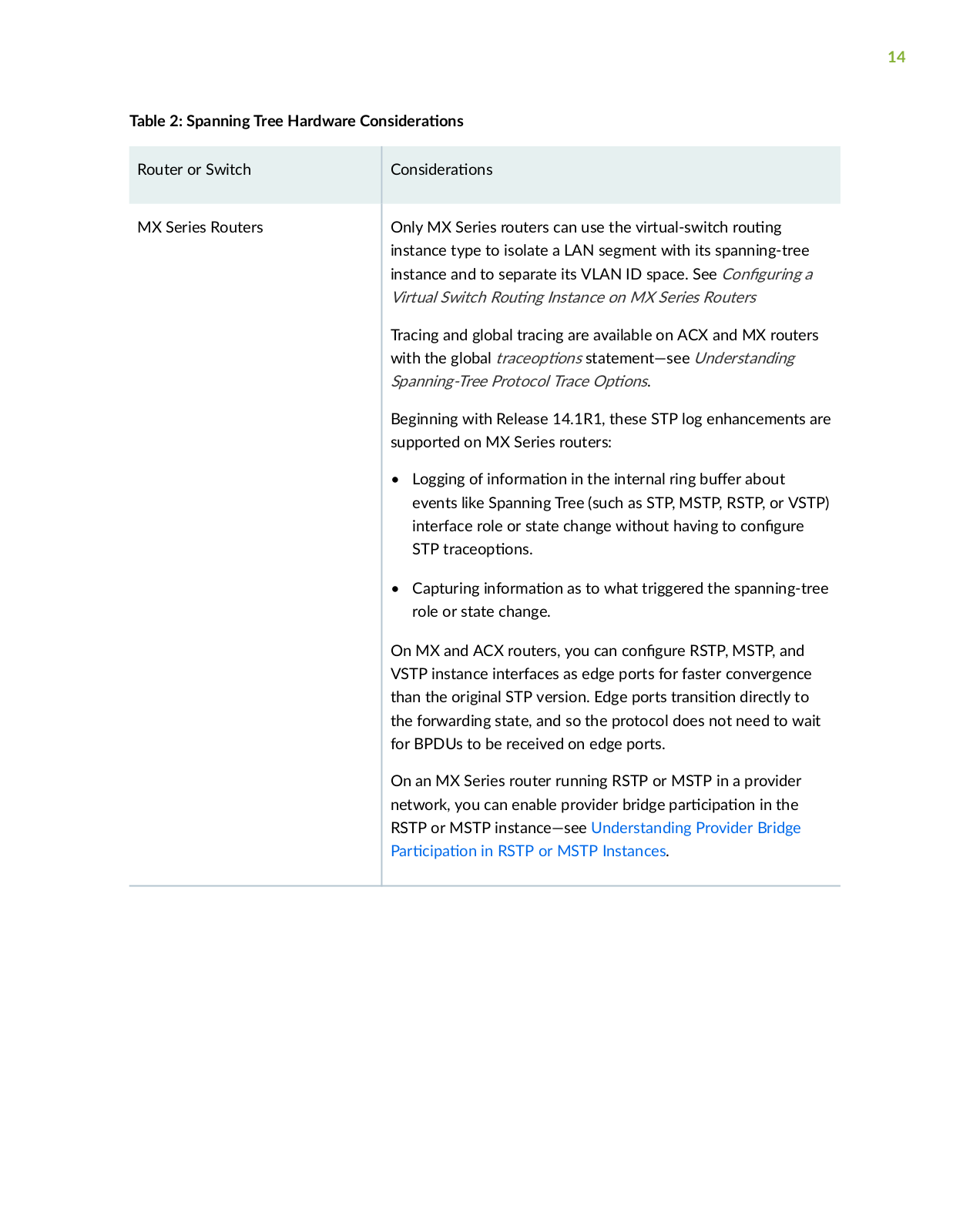
MX Series Routers

Only MX Series routers can use the virtual-switch r

n


instance type to isolate a LAN segment with its spanning-tree


instance and to separate its VLAN ID space. See C n

r n a


Virtual Switch R

n Instance on MX Series Routers


Tracing and global tracing are available on ACX and MX routers


with the global

r c

ns statement—see Understanding


Spanning-Tree Protocol Trace

ns.


Beginning with Release 14.1R1, these STP log enhancements are


supported on MX Series routers:


Logging of n

rm

n in the internal ring b

r about


events like Spanning Tree (such as STP, MSTP, RSTP, or VSTP)


interface role or state change without having to c n

r


STP

r c

ns


Capturing n

rm

n as to what triggered the spanning-tree


role or state change.


On MX and ACX routers, you can c n

r RSTP, MSTP, and


VSTP instance interfaces as edge ports for faster convergence


than the original STP version. Edge ports

r ns

n directly to


the forwarding state, and so the protocol does not need to wait


for BPDUs to be received on edge ports.


On an MX Series router running RSTP or MSTP in a provider


network, you can enable provider bridge

r c

n in the


RSTP or MSTP instance—see Understanding Provider Bridge


r c

n in RSTP or MSTP Instances.


15

Table 2: Spanning Tree Hardware C

ns

r

ns (C n n

)


Router or Switch

C

ns

r

ns


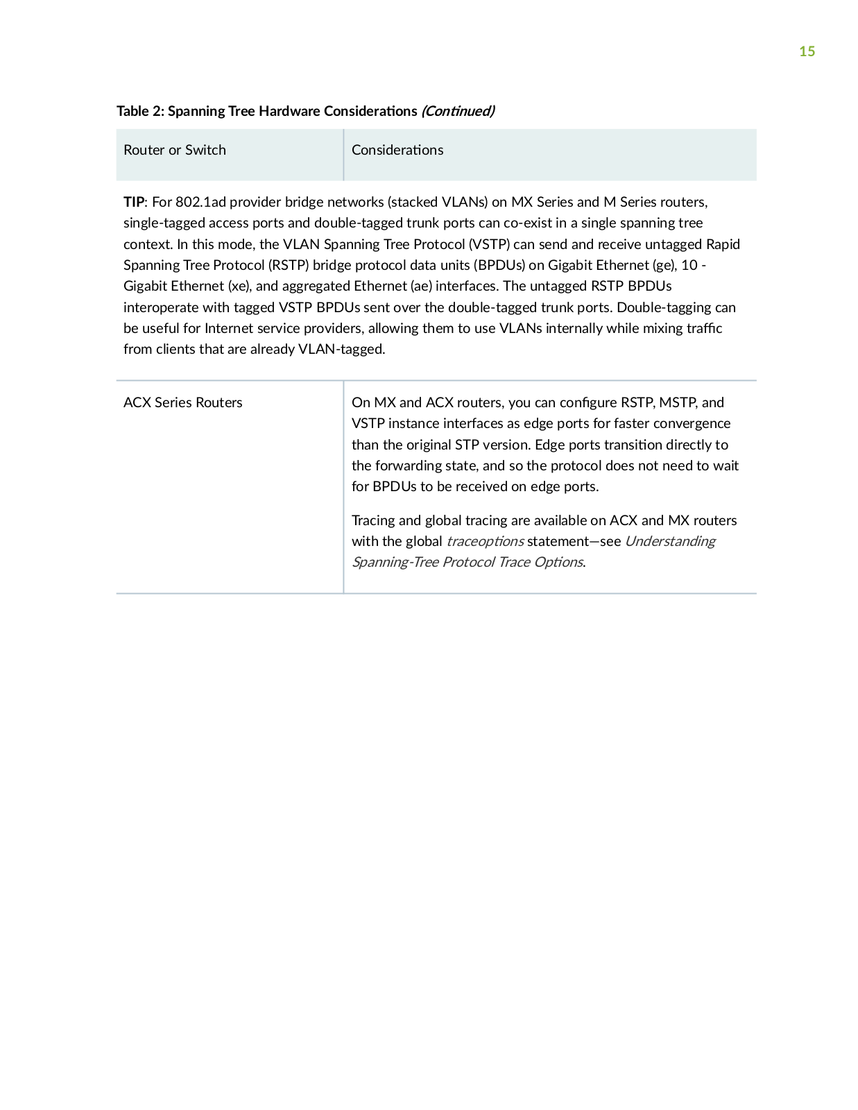
TIP: For 802.1ad provider bridge networks (stacked VLANs) on MX Series and M Series routers, single-tagged access ports and double-tagged trunk ports can co-exist in a single spanning tree context. In this mode, the VLAN Spanning Tree Protocol (VSTP) can send and receive untagged Rapid Spanning Tree Protocol (RSTP) bridge protocol data units (BPDUs) on Gigabit Ethernet (ge), 10 - Gigabit Ethernet (xe), and aggregated Ethernet (ae) interfaces. The untagged RSTP BPDUs interoperate with tagged VSTP BPDUs sent over the double-tagged trunk ports. Double-tagging can be useful for Internet service providers, allowing them to use VLANs internally while mixing r c from clients that are already VLAN-tagged.

ACX Series Routers

On MX and ACX routers, you can c n

r RSTP, MSTP, and


VSTP instance interfaces as edge ports for faster convergence


than the original STP version. Edge ports

r ns n directly to


the forwarding state, and so the protocol does not need to wait


for BPDUs to be received on edge ports.


Tracing and global tracing are available on ACX and MX routers


with the global r c

ns statement—see Understanding


Spanning-Tree Protocol Trace

ns.


16

Table 2: Spanning Tree Hardware C

ns

r

ns (C n

n )


Router or Switch


C

ns

r

ns


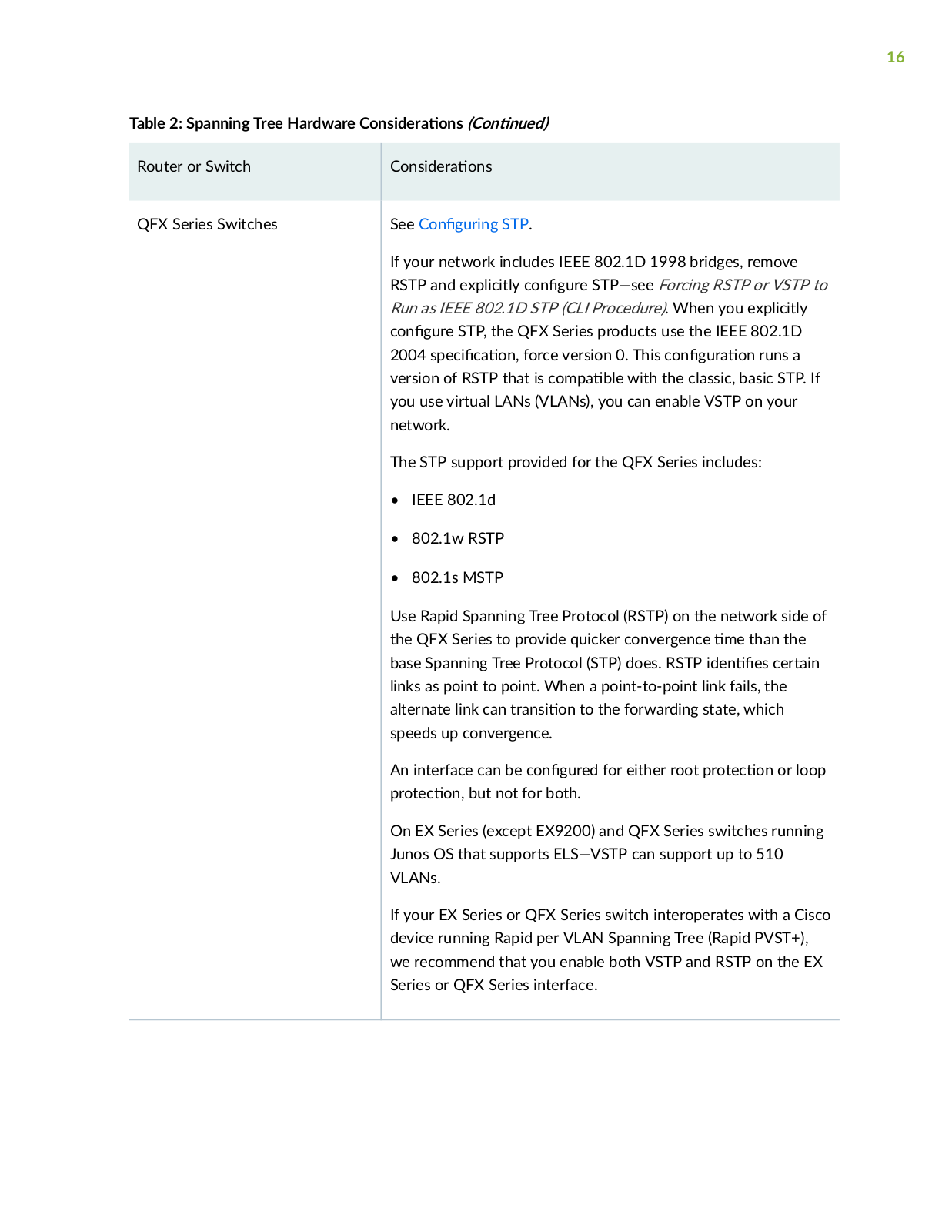
QFX Series Switches


See C n

r n

STP.

If your network includes IEEE 802.1D 1998 bridges, remove

RSTP and explicitly c n r STP—see Forcing RSTP or VSTP to

Run as IEEE 802.1D STP (CLI Procedure). When you explicitly

c n

r STP, the QFX Series products use the IEEE 802.1D

2004 s

c c n force version

0. This c n r n runs a

version of RSTP that is c m b

with the classic, basic STP. If

you use virtual LANs (VLANs), you can enable VSTP on your network.

The STP support provided for the QFX Series includes:

IEEE 802.1d

802.1w RSTP

802.1s MSTP

Use Rapid Spanning Tree Protocol (RSTP) on the network side of

the QFX Series to provide quicker convergence

m

than the

base Spanning Tree Protocol (STP) does. RSTP

n

s certain

links as point to point. When a point-to-point link fails, the

alternate link can r ns

n to the forwarding state, which

speeds up convergence.


An interface can be c n

r for either root r

c

n or loop

rc n but not for both.

On EX Series (except EX9200) and QFX Series switches running

Junos OS that supports ELS—VSTP can support up to 510

VLANs.

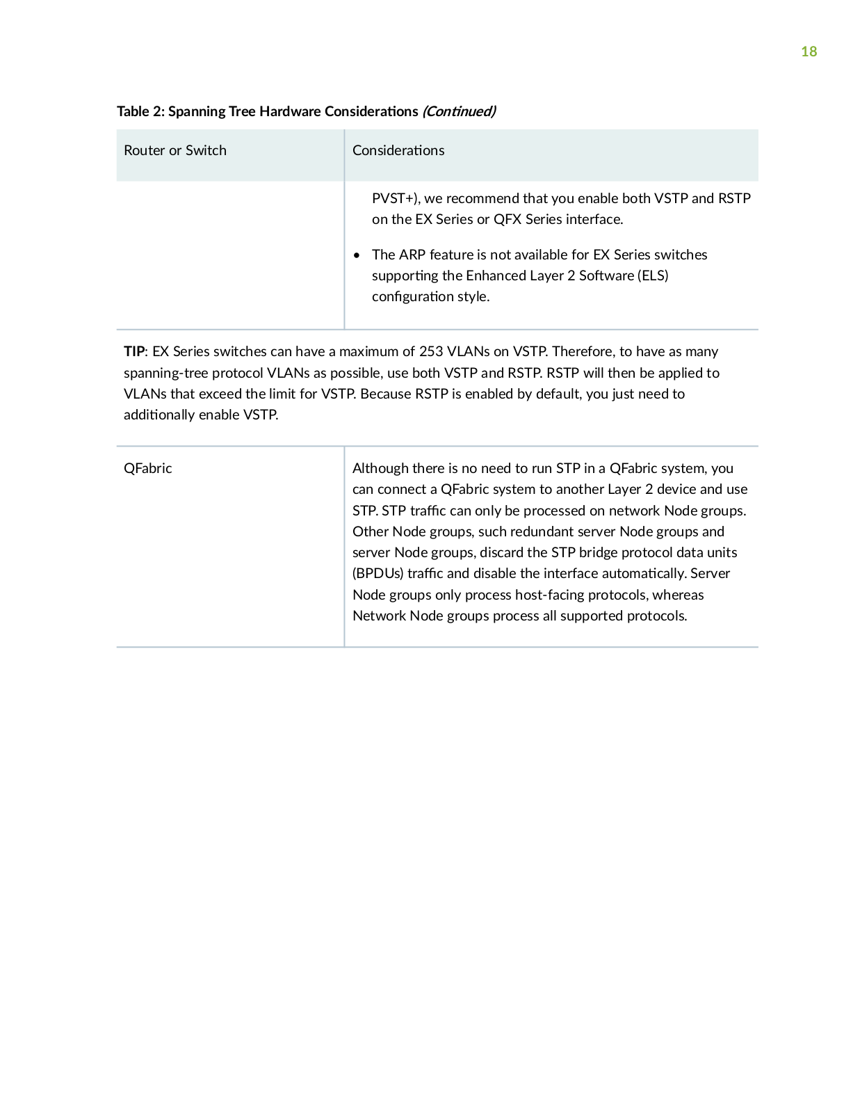
If your EX Series or QFX Series switch interoperates with a Cisco device running Rapid per VLAN Spanning Tree (Rapid PVST+), we recommend that you enable both VSTP and RSTP on the EX Series or QFX Series interface.

17

Table 2: Spanning Tree Hardware C ns r

ns (C n n

)

Router or Switch

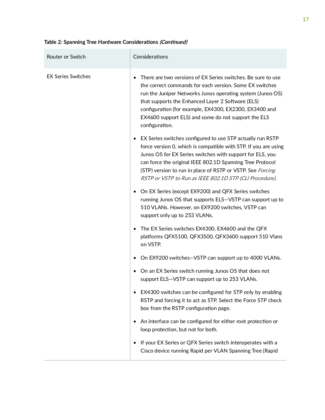
EX Series Switches

C ns r ns

There are two versions of EX Series switches. Be sure to use the correct commands for each version. Some EX switches

run the Juniper Networks Junos

r

n system (Junos OS)

that supports the Enhanced Layer 2 S

w r (ELS)

c n

r

n (for example, EX4300, EX2300, EX3400 and

EX4600 support ELS) and some do not support the ELS

c n

r

n


• EX Series switches c n

r

to use STP actually run RSTP

force version 0, which is c

m


b with STP. If you are using

Junos OS for EX Series switches with support for ELS, you can force the original IEEE 802.1D Spanning Tree Protocol (STP) version to run in place of RSTP or VSTP. See Forcing RSTP or VSTP to Run as IEEE 802.1D STP (CLI Procedure).

On EX Series (except EX9200) and QFX Series switches running Junos OS that supports ELS—VSTP can support up to 510 VLANs. However, on EX9200 switches, VSTP can support only up to 253 VLANs.

The EX Series switches EX4300, EX4600 and the QFX

rms QFX5100, QFX3500, QFX3600 support 510 Vlans on VSTP.

On EX9200 switches—VSTP can support up to 4000 VLANs.

On an EX Series switch running Junos OS that does not support ELS—VSTP can support up to 253 VLANs.

EX4300 switches can be c

n

r for STP only by enabling


RSTP and forcing it to act as STP. Select the Force STP check


box from the RSTP c n

r

n page.

An interface can be c n

r

for either root r c n or

loop r c n but not for both.

If your EX Series or QFX Series switch interoperates with a Cisco device running Rapid per VLAN Spanning Tree (Rapid

18

Table 2: Spanning Tree Hardware C

ns

r

ns (C n n

)


Router or Switch


C

ns

r

ns


PVST+), we recommend that you enable both VSTP and RSTP on the EX Series or QFX Series interface.

• The ARP feature is not available for EX Series switches

s

r n

the Enhanced Layer 2 S w r (ELS)

c n

r

n style.

TIP: EX Series switches can have a maximum of 253 VLANs on VSTP. Therefore, to have as many spanning-tree protocol VLANs as possible, use both VSTP and RSTP. RSTP will then be applied to VLANs that exceed the limit for VSTP. Because RSTP is enabled by default, you just need to

n y enable VSTP.

QFabric

Although there is no need to run STP in a QFabric system, you


can connect a QFabric system to another Layer 2 device and use


STP. STP r

c can only be processed on network Node groups.


Other Node groups, such redundant server Node groups and


server Node groups, discard the STP bridge protocol data units


(BPDUs) r

c and disable the interface

m c y Server


Node groups only process host-facing protocols, whereas


Network Node groups process all supported protocols.


Loading...
+ 463 hidden pages