

Page 1

Security Threat Response Manager
STRM Administration Guide
Release 2008.2
Juniper Networks, Inc.
1194 North Mathilda Avenue
Sunnyvale, CA 94089
USA
408-745-2000
www.juniper.net
Part Number: 530-025612-01, Revision 1
Page 2

Copyright Notice
Copyright © 2008 Juniper Networks, Inc. All rights reserved. Juniper Networks and the Juniper Networks logo are registered trademarks of Juniper
Networks Inc. in the United States and other countries. All other trademarks, service marks, registered trademarks, or registered service marks in this
document are the property of Juniper Networks or their respective owners. All specifications are subject to chang e without notice. Juniper Networks
assumes no responsibility for any inaccuracies in this document or for any obligation to update information in this document. Juniper Networks reserves
the right to change, modify, transfer, or otherwise revise this publicati on without notice.
FCC Statement
The following information is for FCC compliance of Class A devices: This equipment has been tested and found to comply with the limits for a Class A
digital device, pursuant to part 15 of the FCC rules. These limits are designed to provide reasonable protection against harmful interference when the
equipment is operated in a commercial environment. The equipment generates, uses, and can radiate radio-frequency energy and, if not installed and
used in accordance with the instruction manual, may cause harmful interference to radio communications. Operation of this equipment in a residential
area is likely to cause harmful interference, in which case users will be required to correct the interference at their own expense. The following
information is for FCC compliance of Class B devices: The equipment described in this manual generates and may radiate radio-frequency energy. If it
is not installed in accordance with NetScreen’s installation instructions, i t may cause interference wi th radio and tele vision reception. This equip ment has
been tested and found to comply with the limits for a Class B digital device in accordance with the specifications in part 15 of the FCC rules. These
specifications are designed to provide reasonable protection against such interference in a residential installation. However, there is no guarantee that
interference will not occur in a particular installation. If this equipmen t does cause harmful interference to radio or television reception, which can be
determined by turning the equipment off and on, the user is encouraged to try to correct the interference by one or more of the following measures:
Reorient or relocate the receiving antenna. Increase the separation between the equipme nt and receive r. Consult t he dealer o r an experienced ra dio/TV
technician for help. Connect the equipment to an outlet on a circuit different from that to which the receiver is connected.
Caution: Changes or modifications to this product could void the user's warrant y and authority to operate this device.
Disclaimer
THE SOFTWARE LICENSE AND LIMITED WARRANTY FOR THE ACCOMPANYING PRODUCT ARE SET FORTH IN THE INFORMATION PACKET
THAT SHIPPED WITH THE PRODUCT AND ARE INCORPORATED HEREIN BY THIS REFERENCE. IF YOU ARE UNABLE TO LOCATE THE
SOFTWARE LICENSE OR LIMITED WARRANTY, CONTACT YOUR JUNIPER NETWORKS REPRESENTATIVE FOR A COPY.
STRM Administration Guide
Release 2008.2
Copyright © 2008, Juniper Networks, Inc.
All rights reserved. Printed in USA.
Revision History
June 2008—Revision 1
The information in this document is current as of the date listed in the revision history.
2
Page 3

CONTENTS
ABOUT THIS GUIDE
Audience 1
Conventions 1
Technical Documentation 1
Documentation Feedback 1
Requesting Support 2
1 OVERVIEW
About the Interface 3
Accessing the Administration Console 4
Using the Interface 4
Deploying Changes 5
Viewing STRM Audit Logs 5
Logged Actions 5
Viewing the Log File 8
2 MANAGING USERS
Managing Roles 11
Creating a Role 11
Editing a Role 14
Managing User Accounts 15
Creating a User Account 15
Editing a User Account 17
Disabling a User Account 17
Authenticating Users 18
3 SETTING UP STRM
Managing Your License Keys 21
Updating your License Key 22
Exporting Your License Key Information 23
Creating Your Network Hierarchy 24
Considerations 24
Defining Your Network Hierarchy 25
Scheduling Automatic Updates 28
Scheduling Automatic Updates 29
Updating Your Files On-Demand 30
Page 4

Configuring STRM Settings 31
Configuring System Notifications 36
Configuring the Console Settings 39
Starting and Stopping STRM 41
Resetting SIM 41
Accessing the Embedded SNMP Agent 42
Configuring Access Settings 43
Configuring Firewall Access 43
Updating Your Host Set-up 45
Configuring Interface Roles 46
Changing Passwords 47
Updating System Time 48
4 MANAGING BACKUP AND RECOVERY
Managing Backup Archives 53
Viewing Back Up Archives 53
Importing an Archive 54
Deleting a Backup Archive 55
Backing Up Your Information 56
Scheduling Your Backup 56
Initiating a Backup 58
Restoring Your Configuration Information 59
5 USING THE DEPLOYMENT EDITOR
About the Deployment Editor 62
Accessing the Deployment Editor 63
Using the Editor 63
Creating Your Deployment 65
Before you Begin 65
Editing Deployment Editor Preferences 66
Building Your Flow View 66
Adding STRM Components 67
Connecting Components 69
Connecting Deployments 70
Renaming Components 73
Building Your Event View 73
Adding Components 75
Connecting Components 77
Forwarding Normalized Events 77
Renaming Components 80
Managing Your System View 80
Setting Up Managed Hosts 81
Using NAT with STRM 87
Configuring a Managed Host 91
Assigning a Component to a Host 91
Configuring Host Context 92
Configuring STRM Components 95
Page 5

Configuring a Flow Collector 95
Configuring a Flow Processor 98
Configuring a Classification Engine 104
Configuring an Update Daemon 106
Configuring a Flow Writer 108
Configuring an Event Collector 109
Configuring an Event Processor 110
Configuring the Magistrate 112
6 MANAGING FLOW SOURCES
About Flow Sources 115
NetFlow 115
sFlow 116
J-Flow 117
Packeteer 117
Flowlog File 118
Managing Flow Sources 118
Adding a Flow Source 118
Editing a Flow Source 120
Enabling/Disabling a Flow Source 121
Deleting a Flow Source 122
Managing Flow Source Aliases 122
Adding a Flow Source Alias 122
Editing a Flow Source Alias 123
Deleting a Flow Source Alias 124
7 MANAGING SENTRIES
About Sentries 125
Viewing Sentries 126
Editing Sentry Details 127
Managing Packages 132
Creating a Sentry Package 132
Editing a Sentry Package 134
Managing Logic Units 135
Creating a Logic Unit 135
Editing a Logic Unit 138
8 MANAGING VIEWS
Using STRM Views 139
About Views 139
About Global Views 140
Defining Unique Objects 141
Managing Ports View 142
Default Ports Views 142
Adding a Ports Object 142
Editing a Ports Object 144
Page 6

Managing Application Views 146
Default Application Views 146
Adding an Applications Object 147
Editing an Applications Object 149
Managing Remote Networks View 151
Default Remote Networks Views 151
Adding a Remote Networks Object 151
Editing a Remote Networks Object 153
Managing Remote Services Views 154
Default Remote Services Views 154
Adding a Remote Services Object 155
Editing a Remote Services Object 156
Managing Collector Views 158
Adding a Flow Collector Object 158
Editing a Flow Collector Object 159
Managing Custom Views 161
About Custom Views 161
Editing Custom Views 170
Editing the Equation 171
Enabling and Disabling Views 172
Using Best Practices 174
9 CONFIGURING RULES
Viewing Rules 176
Enabling/Disabling Rules 177
Creating a Rule 177
Event Rule Tests 194
Offense Rule Tests 203
Copying a Rule 208
Deleting a Rule 208
Grouping Rules 209
Viewing Groups 209
Creating a Group 209
Editing a Group 211
Copying an Item to Another Group(s) 211
Deleting an Item from a Group 213
Assigning an Item to a Group 213
Editing Building Blocks 213
10 DISCOVERING SERVERS
11 FORWARDING SYSLOG DATA
Adding a Syslog Destination 219
Editing a Syslog Destination 220
Delete a Syslog Destination 221
Page 7

A JUNIPER NETWORKS MIB
B ENTERPRISE TEMPLATE DEFAULTS
Default Sentries 237
Default Custom Views 245
IP Tracking Group 245
Threats Group 246
Attacker Target Analysis Group 249
Target Analysis Group 250
Policy Violations Group 251
ASN Source Group 252
ASN Destination Group 252
IFIndexIn Group 252
IFIndexOut Group 252
QoS Group 252
Flow Shape Group 253
Default Rules 254
Default Building Blocks 266
C UNIVERSITY TEMPLATE DEFAULTS
Default Sentries 281
Default Custom Views 289
IP Tracking Group 289
Threats Group 290
Attacker Target Analysis Group 293
Target Analysis Group 294
Policy Violations Group 295
ASN Source Group 296
ASN Destination Group 296
IFIndexIn Group 296
IFIndexOut Group 296
QoS Group 296
Flow Shape Group 297
Default Rules 298
Default Building Blocks 310
D ISP TEMPLATE DEFAULTS
Default Sentries 325
Default Custom Views 328
IP Tracking Group 328
Threats Group 329
Attacker Target Analysis Group 332
Target Analysis Group 333
Policy Violations Group 334
ASN Source Group 335
ASN Destination Group 335
Page 8

IFIndexIn Group 335
IFIndexIn Group 335
QoS Group 335
Flow Shape Group 336
Default Rules 337
Default Building Blocks 346
INDEX
Page 9

ABOUT THIS GUIDE
The STRM Administration Guide provides you with information for managing
STRM functionality requiring administrative access.
Audience This guide is intended for the system administrator responsible for setting up
STRM in your network. This guide assumes that you have STRM administrative
access and a knowledge of your corporate network and networking technologies.
Conventions Table 1 lists conventions that are used throughout this guide.
Table 1 Icons
Icon Type Description
Information note Information that describes important features or
instructions.
Technical
Documentation
Documentation
Feedback
Caution Information that alerts you to potential loss of
data or potential damage to an application,
system, device, or network.
Warning Information that alerts you to potential personal
injury.
You can access technical documentation, technical notes, and release notes
directly from the Juniper networks Support Web site at
www.juniper.net/support/.
http://
We encourage you to provide feedback, comments, and suggestions so that we
can improve the documentation. Send your comments to
techpubs-comments@juniper.net, or fill out the documentation feedback form at
http://www.juniper.net/techpubs/docbug/docbugreport.html. If you are using e-mail, be
sure to include the following information with your comments:
• Document name
• Document part number
STRM Administration Guide
Page 10

2 ABOUT THIS GUIDE
• Page number
• Software release version
Requesting
Support
• Open a support case using the Case Management link at
http://www.juniper.net/support/ or call 1-888-314-JTAC (from the United States,
Canada, or Mexico) or 1-408-745-9500 (from elsewher e).
STRM Administration Guide
Page 11

OVERVIEW
1
This chapter provides an overview of the STRM Administration Console and
STRM administrative functionality including:
• About the Interface
• Accessing the Administration Console
• Using the Interface
• Deploying Changes
• Viewing STRM Audit Logs
About the Interface Y ou must have administrative privileges to access the Administration Console. The
STRM Administration Console provides access to following administrative
functionality:
• Manage users. See Chapter 2 Managing Users.
• Manage STRM. See Chapter 3 Setting Up STRM.
• Backup and recover your data. See Chapter 4 Managing Backup and
Recovery.
• Manage your deployment views. See Chapter 5 Using the Deployment Editor.
• Managing flow sources. See Chapter 6 Managing Flow Sources.
• Configure sentries. See Chapter 7 Managing Sentries.
• Configure views. See Chapter 8 Managing Views.
• Configure syslog forwarding. See Chapter 11 Forwarding Syslog Data.
All configuration updates using the Administration Console are saved to a staging
area. Once all changes are complete, you can deploy the configuration changes or
all configuration settings to the remainder of your deployment.
STRM Administration Guide
Page 12
4 OVERVIEW
Accessing the
Administration
Console
You can access the STRM Administration Console through the main STRM
interface. To access the Administration Console, click Config in the main STRM
interface. The Administration Console appears.
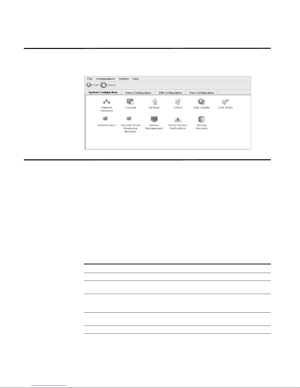
Using the Interface The Administration Console provides several tab and menu options that allow you
to configure STRM including:
• System Configuration - Provides access to administrative functionality, such
as, user management, automatic updates, license key, network hierarchy,
sentries, STRM settings, system notifications, backup and recovery and
Console configuration.
• Views Configuration - Provides access to STRM views.
• SIM Configuration - Provides access to scanners, sensor device
management, syslog forwarding, and reset the SIM model.
• Flow Configuration - Provides access to flow source configuration, such as
NetFlow.
The Administration Console also includes several menu options including:
Table 1-1 Administrative Console Menu Options
Menu Option Sub-Menu Description
File Close Closes the Administration Console.
Configurations Deployment Editor Opens the deployment editor
interface.
Deploy configuration
changes
Deploy All Deploys all configuration settings to
System STRM Start Starts the STRM application.
STRM Stop Stops the STRM application.
Deploys any configuration changes
from the current session to your
deployment.
your deployment.
STRM Administration Guide
Page 13

Deploying Changes 5
Table 1-1 Administrative Console Menu Options (continued)
Menu Option Sub-Menu Description
STRM Restart Restarts the STRM application.
Help Help and Support Opens user documentation.
About STRM
Administration Console
Displays version information.
The Administration Console provides several toolbar options including:
Table 1-2 Administration Console Toolbar Options
Icon Description
Opens the deployment editor interface.
Deploys all changes made through the Administration Console.
Deploying Changes Once you update your configuration settings using the Administration Console,
you must save those changes to the staging area. You must either manually
deploy all changes using the Deploy menu option or, upon exit, a window appears
prompting you to deploy changes before you exit. All deployed changes are then
enforced throughout your deployment.
Using the Administration Console menu, you can deploy changes as follows:
• Deploy All - Deploys all configuration settings to your deployment.
• Deploy configuration changes - Deploys any configuration changes from the
current session to your deployment.
Viewing STRM
Audit Logs
Changes made by STRM users are recorded in the audit logs. You can view the
audit logs to monitor changes to STRM and the users performing those changes.
All audit logs are stored in plain text and are archived and compressed once the
audit log file reaches a size of 200 MB. The current log file is named
Once the file reaches a size of 200 MB, the file is compressed and renamed as
follows:
audit.1.gz, audit.2.gz, etc with the file number incrementing each
time a log file is archived. STRM stores up to 50 archived log files.
This section provides information on using the audit logs including:
• Logged Actions
• Viewing the Log File
Logged Actions STRM logs the following categories of actions in the audit log file:
audit.log.
STRM Administration Guide
Page 14

6 OVERVIEW
Table 1-3 Logged Actions
Category Action
User Authentication Log in to STRM
User Authentication Log out of STRM
Administrator Authentication Log in to the STRM Administration Consol e
Administrator Authentication Log out of the STRM Administration Console
Root Login Log in to STRM, as root
Log out of STRM, as root
Rules Adding a rule
Deleting a rule
Editing a rule
Sentry Adding a sentry
Editing a sentry
Deleting a sentry
Editing a sentry package
Editing sentry logic
User Accounts Adding an account
Editing an account
Deleting an account
User Roles Adding a role
Editing a role
Deleting a role
Sensor Devices Adding a sensor device
Editing a sensor device
Deleting a sensor device
Adding a sensor device group
Editing a sensor device group
Deleting a sensor device group
Sensor Device Extension Adding an sensor device extension
Editing the sensor device extension
Deleting a sensor device extension
Uploading a sensor device extension
Uploading a sensor device extension
successfully
Downloading a sensor device extension
Reporting a sensor device extension
Modifying a sensor devices association to a
device or device type.
STRM Administration Guide
Page 15

Viewing STRM Audit Logs 7
Table 1-3 Logged Actions
Category Action
Protocol Configuration Adding a protocol configuration
Deleting a protocol configuration
Editing a protocol configuration
Flow Sources Adding a flow source
Editing a flow source
Deleting a flow source
Offense Manager Hiding an offense
Closing an offense
Closing all offenses
TNC Recommendations Creating a recommendation
Editing a recommendation
Deleting a recommendation
Syslog Forwarding Adding a syslog forwarding
Deleting a syslog forwarding
Editing a syslog forwarding
Reports Adding a template
Deleting a template
Editing a template
Executing a template
Deleting a report
Groups Adding a group
Deleting a group
Editing a group
Backup and Recovery Editing the configuration
Initiating the backup
Completing the backup
Failing the backup
Deleting the backup
Synchronizing the backup
Cancelling the backup
Initiating the restore
Uploading a backup
Uploading an invalid backup
Deleting the backup
STRM Administration Guide
Page 16

8 OVERVIEW
Table 1-3 Logged Actions
Category Action
Scanner Adding a scanner
Scanner Schedule Adding a schedule
Asset Deleting all assets
License Adding a license key.
Viewing the Log File To view the audit logs:
Step 1 Log in to STRM as root.
Step 2 Go to the following directory:
/var/log/audit
Deleting a scanner
Editing a scanner
Editing a schedule
Deleting a schedule
Editing a license key.
Step 3 Open the desired audit log file.
Each entry in the log file displays using the following format:
Note: The maximum size of any audit message (not including date, time, and host
name) is 1024 characters.
<date_time> <host name> <user>@<IP address> (thread ID)
[<category>] [<sub-category>] [<action>] <payload>
Where:
<date_time> is the date and time of the activity in the format: Month Date
HH:MM:SS.
<host name> is the host name of the Console where this activity was logged.
<user> is the name of the user that performed the action.
<IP address> is the IP address of the user that performed the action.
(thread ID) is the identifier of the Java thread that logged this activity.
<category> is the high-level category of this activity.
<sub-category> is the low-level category of this activity.
<action> is the activity that occurred.
<payload> is the complete record that has changed, if any. This may include a
user record or an event rule.
For example:
Nov 6 12:22:31 localhost.localdomain admin@10.100.100.15
(Session) [Authentication] [User] [Login]
STRM Administration Guide
Page 17

Viewing STRM Audit Logs 9
Nov 6 12:22:31 localhost.localdomain jsam@10.100.100.15 (0)
[Configuration] [User Account] [Account Modified]
username=james, password=/oJDuXP7YXUYQ, networks=ALL,
email=sam@q1labs.com, userrole=Admin
Nov 13 10:14:44 localhost.localdomain admin@10.100.45.61 (0)
[Configuration] [FlowSource] [FlowSourceModified] Flowsource(
name="tim", enabled="true", deployed="false",
asymmetrical="false", targetQflow=DeployedComponent(id=3),
flowsourceType=FlowsourceType(id=6),
flowsourceConfig=FlowsourceConfig(id=1))
STRM Administration Guide
Page 18

Page 19

MANAGING USERS
2
This chapter provides information on managing STRM users including:
• Managing Roles
• Managing User Accounts
• Authenticating Users
You can add or remove user accounts for all users that you wish to access STRM.
Each user is associated with a role, which determines the privileges the user has
to functionality and information within STRM. You can also restrict or allow access
to areas of the network.
Managing Roles You must create a role before you can create user accounts. By default, STRM
provides a default administrative role, which provides access to all areas of STRM.
A user that has been assigned administrative privileges (including the default
administrative role) cannot edit their own account. Another administrative user
must make any desired changes.
Using the Administration Console, you can:
• Create a role. See Creating a Role.
• Edit a role. See Editing a Role
Creating a Role To create a role:
Step 1 In the Administration Console, click the System Configuration tab.
The System Configuration panel appears.
Step 2 Click the User Roles icon.
The Manage User Roles window appears.
Step 3 Click Create Role.
STRM Administration Guide
Page 20
12 MANAGING USERS
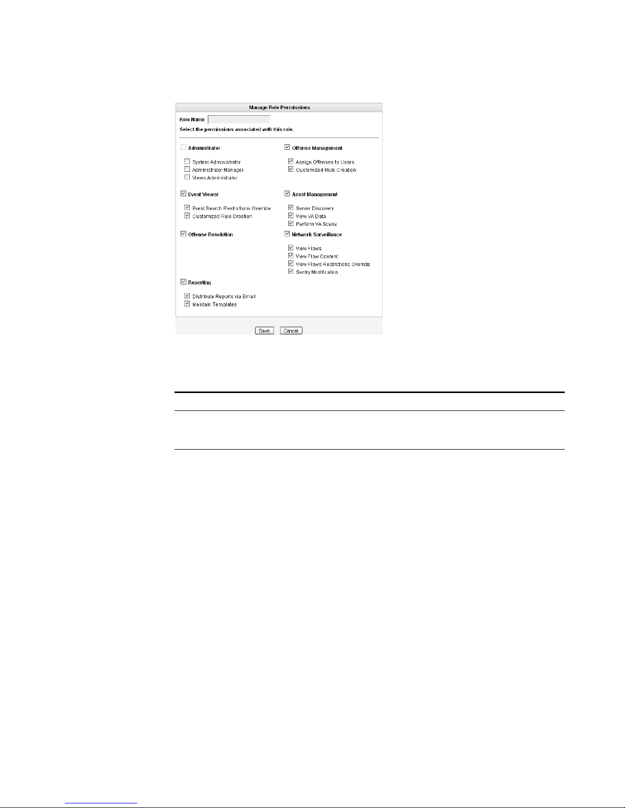
Step 4 Enter values for the parameters. You must select at least one permission to
proceed.
Table 2-1 Create Roles Parameters
Parameter Description
Role Name Specify the name of the role. The name can be up to 15
characters in length and must only contain integers and
letters.
Administrator Select the check box if you wish to grant this user
administrative access to the STRM interface. Within the
administrator role, you can grant additional access to the
following:
• System Administrator - Select this check box if you wish
to allow users access to all areas of STRM except Views.
Also users with this access are not able to edit other
administrator accounts.
• Administrator Manager - Select this check box if you
wish to allow users the ability to create and edit other
administrative user accounts. If you select this check box,
the System Administrator check box is automatically
selected.
• Views Administrator - Select this check box if you wish
to allow users the ability to create, edit, or delete Views.
For example, the Application View and the Ports View.
STRM Administration Guide
Page 21

Managing Roles 13
Table 2-1 Create Roles Parameters (continued)
Parameter Description
Offense Management Select the check box if you wish to grant this user access to
Offense Manager functionality. Within the Offense Manager
functionality, you can grant additional access to the
following:
• Assign Offenses to Users - Select the check box if you
wish to allow users to assign offenses to other users.
• Customized Rule Creation - Select the check box if you
wish to allow users to create custom rules.
For more information on the Offense Manager, see the
STRM Users Guide.
Event Viewer Select the check box if you wish this user to have access to
the Event Viewer. Within the Event Viewer, you can also
grant users additional access to the following:
• Event Search Restrictions Override - Select the check
box if you wish to allow users the ability to override event
search restrictions.
• Customized Rule Creation functionality - Select the
check box if you wish to allow users to create rules using
the Event Viewer.
For more information on the Event Viewer, see the STRM
Users Guide.
Asset Management Select the check box if you wish to grant this user access to
Asset Management functionality. Within the Asset
Management functionality, you can grant additional access
to the following:
• Server Discovery - Select the check box if you wish to
allow users the ability to discover servers.
• View VA Data - Select the check box if you wish to allow
users access to vulnerability assessment data.
• Perform VA Scans - Select the check box if you wish to
allows users to perform vulnerability assessment scans.
STRM Administration Guide
Page 22

14 MANAGING USERS
Table 2-1 Create Roles Parameters (continued)
Parameter Description
Network Surveillance Select the check box if you wish to grant this user access to
Network Surveillance functionality. Within the Network
Surveillance functionality, you can grant additional access to
the following:
• View Flows - Select the check box if you wish to allow
users access to content captured using the View Flows
function.
• View Flow Content - Select the check box if you wish to
allow users access to data accessed through the View
Flow box.
• View Flows Restrictions Override - Select the check
box if you wish to allow users the ability to override sentry
restrictions.
• Sentry Modification - Select the check box if you wish to
allows users to modify existing sentries.
For more information, see the STRM Users Guide.
Reporting Select the check box if you wish to grant this user access to
Reporting functionality. Within the Reporting functionality,
you can grant users additional access to the following:
• Distribute Reports via Email - Select the check box if
you wish to allow users to distribute reports throug h
e-mail.
• Maintain Templates - Select the check box if you wish to
allow users to maintain reporting templates.
For more information, see the STRM Users Guide.
Step 5 Click Save.
Step 6 Click Return.
Step 7 Close the Manage Roles window.
The STRM Administration Console appears.
Step 8 From the menu, select Configurations > Deploy configuration changes.
Editing a Role To edit a role:
Step 1 In the Administration Console, click the System Configuration tab.
The System Configuration panel appears.
Step 2 Click the User Roles icon.
The Manage Role window appears.
Step 3 For the role you wish to edit, click the edit icon.
The Permissions for Role window appears.
Step 4 Update the permissions (see Table 2-1), as necessary.
STRM Administration Guide
Page 23
Managing User Accounts 15
Step 5 Click Return.
Step 6 Click Save.
Step 7 Close the Manage User Roles window.
The STRM Administration Console appears.
Step 8 From the menu, select Configurations > Deploy configuration changes.
Managing User
Accounts
Creating a User
Account
You can create a STRM user account, which allows a user access to selected
network components using the STRM interface. You can also create multiple
accounts for your system that include administrative privileges. Only the main
administrative account can create accounts that have administrative privileges.
You can create and edit user accounts to access STRM including:
• Creating a User Account
• Editing a User Account
• Disabling a User Account
To create an account for a STRM user:
Step 1 In the Administration Console, click the System Configuration tab.
The System Configuration panel appears.
Step 2 Click the Users icon.
The Manage Users window appears.
Step 3 In the Manage Users area, click Add.
The User Details window appears.
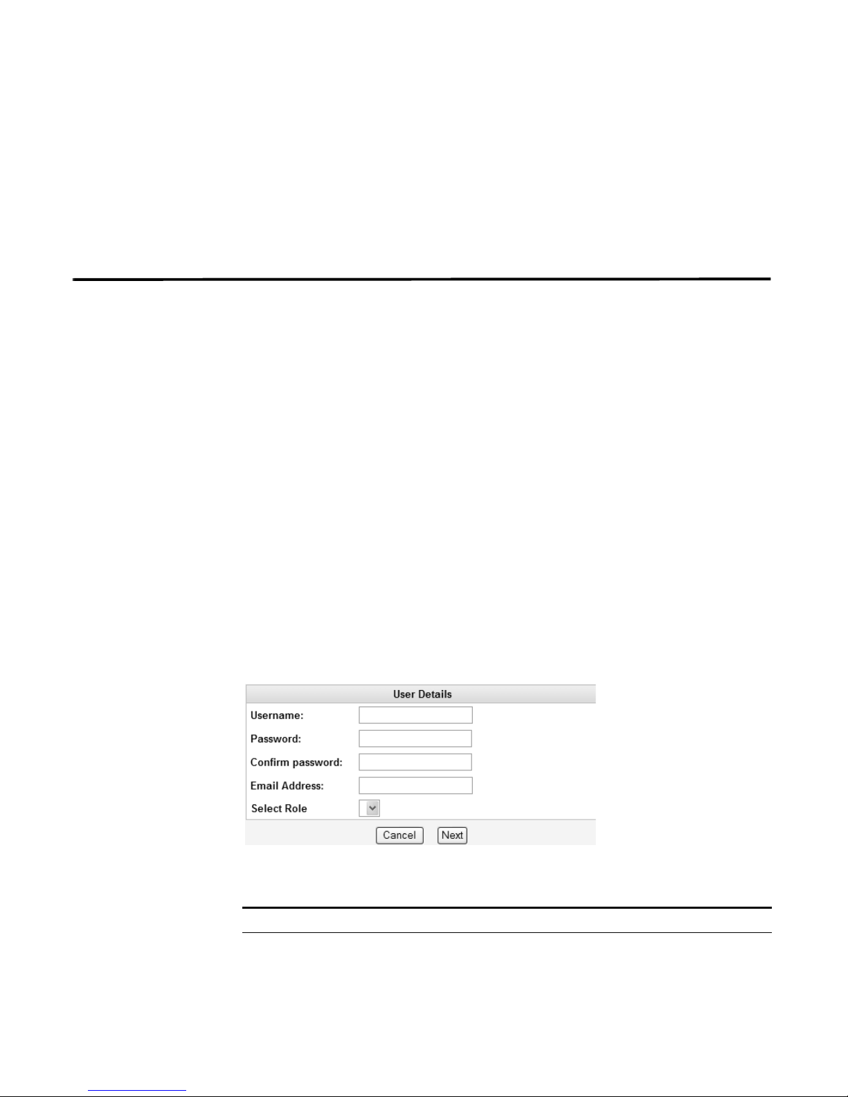
Step 4 Enter values for the following parameters:
Table 2-2 User Details Parameters
Parameter Description
Username Specify a username for the new user. The username must not
include spaces or special characters.
STRM Administration Guide
Page 24
16 MANAGING USERS
Step 5 Click Next.
Table 2-2 User Details Parameters (continued)
Parameter Description
Password Specify a password for the user to gain access. The password
must be at least 5 characters in length.
Confirm Password Re-enter the password for confirmation.
Email Address Specify the user’s e-mail address.
Role Using the drop-down list box, select the role you wish this user to
assume. For information on roles, see
Managing Roles. If you
select Admin, this process is complete.
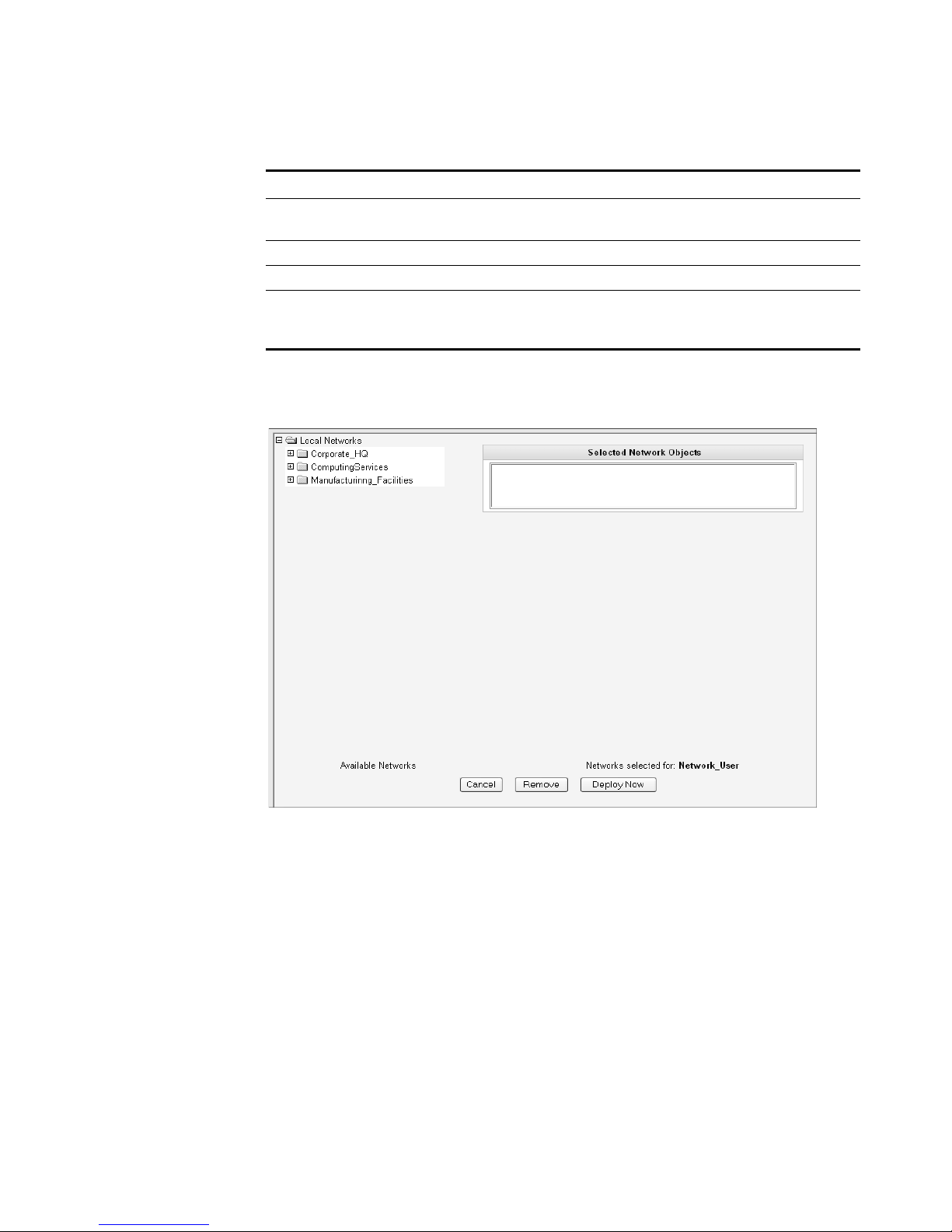
The Selected Network Objects window appears.
Step 6 From the menu tree, select the network objects you wish this user to be able to
monitor.
The selected network objects appear in the Selected Network Object panel.
Step 7 Choose one of the following options:
a Click Deploy Now to deploy new user information immediately.
b Click Cancel to cancel all updates and return to the Manage Users window.
Step 8 Close the Manage Users window.
The STRM Administration Console appears.
STRM Administration Guide
Page 25

Managing User Accounts 17
Editing a User
Account
Step 1 In the Administration Console, click the System Configuration tab.
Step 2 Click the Users icon.
Step 3 In the Manage Users area, click the user account you wish to edit.
Step 4 Update values (see Table 2-2), as necessary.
Step 5 Click Next.
Step 6 From the menu tree, select the network objects you wish this user to access.
Step 7 For all network objects you wish to remove access, select the object from the
Step 8 Choose one of the following options:
To edit a user account:
The System Configuration panel appears.
The Manage Users window appears.
The User Details window appears.
If you are editing a non-administrative user account, the Selected Network Objects
window appears. If you are editing an administrative user account, go to Step 9.
The selected network objects appear in the Selected Network Object panel.
Selected Network Objects panel and click Remove.
a Click Deploy Now to deploy new user information immediately.
Step 9 Close the Manage Users window.
Disabling a User
Account
Step 1 In the Administration Console, click the System Configuration tab.
Step 2 Click the Users icon.
Step 3 In the Manage Users area, click the user account you wish to disable.
Step 4 In the Role drop-down list box, select Disabled.
Step 5 Click Next.
Step 6 Close the Manage Users window.
b Click Cancel to return to cancel all updates and return to the Manage Users
window.
The STRM Administration Console appears.
To disable a user account:
The System Configuration panel appears.
The Manage Users window appears.
The User Details window appears.
The STRM Administration Console appears. This user no longer has access to the
STRM interface. If this user attempts to log in to STRM, the following message
appears: This account has been disabled.
STRM Administration Guide
Page 26

18 MANAGING USERS
Authenticating
Users
You can configure authentication to validate STRM users and passwords. STRM
supports the following user authentication types:
• System Authentication - Users are authenticated lo cally by STRM. This is the
default authentication type.
• RADIUS Authentication - Users are authenticated by a Remote Authentication
Dial-in User Service (RADIUS) server. When a user attempts to login, STRM
encrypts the password only, and forwards the username and password to the
RADIUS server for authentication.
• TACACS Authentication - Users are authenticated by a Terminal Access
Controller Access Control System (TACACS) server. When a user attempts to
login, STRM encrypts the username and password, and forwards this
information to the TACACS server for authentication.
• LDAP/ Active Directory - Users are authenticated by a Lightweight Directory
Access Protocol (LDAP) server using Kerberos.
If you wish to configure RADIUS, TACACS, or LDAP/Active Directory as the
authentication type, you must :
• Configure the authentication server before you con figu re authentication in
STRM.
• Make sure the server has the appropriate user accounts and privilege levels to
communicate with STRM. See your server documentation for more information.
• Make sure the time of the authentication server is synchronized with the time of
the STRM server. For more information on setting STRM time, see Chapter 3
Setting Up STRM.
• Make sure all users have appropriate user accounts and roles in STRM to allow
authentication with the third party servers.
Once authentication is configured and a user enters an invalid username and
password combination, a message appears indicating the login was invalid. if the
user attempts to access the sy st em multiple times using invalid information, the
user must wait the configured amount of time before attempting to access the
system again. For more information on configuring system settings for
authentication, see Chapter 3 Setting Up STRM - Configuring the Console
Settings. An administrative user can always access STRM through a third party
authentication module or by using the local STRM Admin password.
To configure authentication:
Step 1 In the Administration Console, click the System Configuration tab.
The System Configuration panel appears.
Step 2 Click the Authentication icon.
The Authentication window appears.
STRM Administration Guide
Page 27

Authenticating Users 19
Step 3
From the Authentication Module drop-down list box, select the authentication type
you wish to configure.
Step 4 Configure the selected authentication type:
a If you selected System Authentication, go to Step 5
b If you selected RADIUS Authentication, enter values for the following
parameters:
Table 2-3 RADIUS Parameters
Parameter Description
RADIUS Server Specify the hostname or IP address of the RADIUS server.
RADIUS Port Specify the port of the RADIUS server.
Authentication
Type
Specify the type of authentication you wish to perf or m . Th e
options are:
• CHAP (Challenge Handshake Authentication Protocol) -
Establishes a Point-to-Point Protocol (PPP) connection
between the user and the server.
• MSCHAP (Microsoft Challenge Handshake Authentication
Protocol) - Authenticates remote Windows workstations.
• ARAP (Apple Remote Access Protocol) - Establishes
authentication for AppleTalk network traffic.
• ASCII
• PAP (Password Authentication Protocol) - Sends clear text
between the user and the server.
Shared Secret Specify the shared secret that STRM uses to encrypt RADIUS
passwords for transmission to the RADIUS server.
c If you selected TACACS Authentication, enter values for the following
parameters:
Table 2-4 TACACS Parameters
Parameter Description
TACACS Server Specify the hostname or IP address of the TACACS server.
TACACS Port Specify the port of the TACACS server.
STRM Administration Guide
Page 28

20 MANAGING USERS
Table 2-4 TACACS Parameters (continued)
Parameter Description
Authentication
Type
Specify the type of authentication you wish to perform. The
options are:
• PAP (Password Authentication Protocol) - Sends clear text
between the user and the server.
• CHAP (Challenge Handshake Authentication Protocol) -
Establishes a PPP connection between the user and the
server.
• MSCHAP (Microsoft Challenge Handshake Authentication
Protocol) - Authenticates remote Windows workstations.
• MSCHAP2 - (Microsoft Challenge Handshake Authentication
Protocol version 2)- Authenticates remote Windows
workstations using mutual authentication.
• EAPMD5 (Extensible Authentication Protocol using MD5
Protocol) - Uses MD5 to establish a PPP connection.
Shared Secret Specify the shared secret that STRM uses to encrypt TACACS
passwords for transmission to the TACACS server.
d If you selected LDAP/ Active Directory, enter values for the following
parameters:
Table 2-5 LDAP/ Active Directory Parameters
Parameter Description
Server URL Specify the URL used to connect to the LDAP server. For
LDAP Context Specify the LDAP context you wish to use, for example,
LDAP Domain Specify the domain you wish to use, for example q1labs.inc
Step 5 Click Save.
example, ldap://<host>:<port>
DC=Q1LABS,DC=INC.
STRM Administration Guide
Page 29

3
SETTING UP STRM
This chapter provides information on setting up STRM including:
• Managing Your License Keys
• Creating Your Network Hierarchy
• Scheduling Automatic Updates
• Configuring STRM Settings
• Configuring System Notifications
• Configuring the Console Settings
• Starting and Stopping STRM
• Resetting SIM
• Accessing the Embedded SNMP Agent
• Configuring Access Settings
Managing Your
License Keys
For your STRM Console, a default license key provides you access to the interface
for 5 weeks. You must manage your license key using the System Management
window in the STRM Administration Console. This interface prov ides the status of
the license key for each system (host) in your deployment including:
• Valid - The license key is valid.
• Expired - The license key has expired. To update your license key, see
Updating your License Key.
• Override Console License - This host is using the Console license key. You
can use the Console key or apply a license key for this system. If you wish to
use the Console license for any system in your deployment, click Default
License in the Manage License window . The license for that system will default
to the Console license key.
This section provides information on managing your license keys including:
• Updating your License Key
• Exporting Your License Key Information
STRM Administration Guide
Page 30
22 SETTING UP STRM
Updating your
License Key
Step 1 In the Administration Console, click the System Configuration tab.
Step 2 Click the System Management icon.
For your STRM Console, a default license key provides you access to the interface
for 5 weeks. Choose one of the following options for assistance with your license
key:
• For a new or updated license key, please contact your local sales
representative.
• For all other technical issues, please contact Juniper Networks Customer
Support.
If you log in to STRM and your Console license key has expired, you are
automatically directed to the System Management window. You must update the
license key before you can continue. However, if one of your non-Console systems
includes an expired license key, a message appears when you log in indicating a
system requires a new license key. You must navigate to the System Management
window to update that license key.
To update your license key:
The System Configuration panel appears.
The System Management window appears providing a list of all hosts in your
deployment.
Step 3 For the host that on which you wish to update the license key, click the value that
appears in the License column.
Note: If you update the license key for your Console, all systems in your
deployment default to the Console license key at that time.
The Current License Details window appears.
Step 4 Click Browse beside the New License Key File and locate the license key.
STRM Administration Guide
Page 31

Managing Your License Keys 23
Step 5
Step 6 Click Save.
Step 7 Close the license key window.
Step 8 From the menu, select Configurations > Deploy All.
Exporting Your
License Key
Information
Step 1 In the Administration Console, click the System Configuration tab.
Step 2 Click the System Management icon.
Once you locate and select the license key, click Open.
The Current License Details window appears.
A message appears indicating the license key was successfully updated.
Note: If you wish to revert back to the previous license key, click Revert to
Deployed. If you revert to the license key used by the STRM Console system,
click Revert to Console.
The Administration Console appears.
The license key information is updated in your deployment.
To export your license key information for all systems in your deployment:
The System Configuration panel appears.
The System Management window appears providing a list of all hosts in your
deployment.
STRM Administration Guide
Page 32

24 SETTING UP STRM
Step 3 Click Export Licenses.
Step 4 Select one of the following options:
Step 5 Click OK.
The export window appears.
• Open - Opens the license key data in an Excel spreadsheet.
• Save - Allows you to save the file to your desktop.
Creating Your
Network Hierarchy
Considerations Consider the following when defining your network hierarchy:
STRM uses the network hierarchy to understand your network traffic and provide
you with the ability to view network activity for your entire deployment.
When you develop your network hierarchy, you should consider the most effective
method for viewing network activity. Note that the network you configure in STRM
does not have to resemble the physical deployment of your network. STRM
supports any network hierarchy that can be defined by a range of IP addresses.
You can create your network based on many different variables, including
geographical or business units.
• Group together systems and user groups that have similar behavior. This
provides you with a clear view of your network.
• Create multiple top-level groups if your deployment is processing more than
600,000 flows.
• Organize your systems/network by role or similar traffic patterns. For example,
mail servers, departmental users, labs, development groups, or geographically
disperse locations. This allows you to differentiate network behavior and
enforce network management security policies.
• Do not group together servers that have unique behavior with other servers on
your network. For example, placing a unique server alone provides the server
greater visibility in STRM allowing you to enact specific policies.
• Within a group, place servers with high volumes of traffic, such as mail servers,
at the top of the group. This provides you a clear visual representation when a
discrepancy occurs.
• Combine multiple Classless Inter-Domain Routings (CIDRs) or subnets into a
single network/group to conserve disk space. For example:
We recommend that you extend this practice to all views.
STRM Administration Guide
Page 33

Creating Your Network Hierarchy 25
Group Description IP Address
1 Marketing 10.10.5.0/24
2 Sales 10.10.8.0/21
3 Database Cluster 10.10.1.3/32
10.10.1.4/32
10.10.1.5/32
Note: We recommend that you do not configure a network group with more than 15
objects. This may cause you difficulty in viewing detailed information for each
group.
You may also wish to define an all encompassing group so when you define new
networks, the appropriate policies and behavioral monitors are applied. For
example:
Group Subgroup IP Address
Cleveland Cleveland misc 10.10.0.0/16
Cleveland Cleveland Sales 10.10.8.0/21
Cleveland Cleveland Marketing 10.10.1.0/24
Defining Your
Network Hierarchy
Step 1 In the Administration Console, click the System Configuration tab.
Step 2 Click the Network Hierarchy icon.
Step 3 From the menu tree, select the areas of the network you wish to add a network
Step 4 Click Add.
Step 5 Enter your network object values:
If you add a new network to the above example, such as 10.10.50.0/24, which is
an HR department, the traffic appears as Cleveland-based and any policies or
sentries applied to the Cleveland group is applied by default.
To define your netwo rk hierarchy:
The System Configuration panel appears.
The Network Views window appears.
component.
The Manage Group window appears for the selected network component.
The Add Network Object window appears.
Table 3-1 Add New Object Parameters
Parameter Action
Group Specify the group for the new network object. Click Add Group
to specify the group.
STRM Administration Guide
Page 34

26 SETTING UP STRM
Step 6 Click Save.
Step 7 Repeat for all network objects.
Step 8 Click Re-Order.
Step 9 Order the network objects in the desired order.
Step 10 Click Save.
Table 3-1 Add New Object Parameters (continued)
Parameter Action
Name Specify the name for the object.
Weight Specify the weight of the object. The range is 1 to 100 and
indicates the importance of the object in the system.
IP/CIDR(s) Specify the CIDR range(s) for this object. For more information
on CIDR values, see
Accepted CIDR Values.
Description Specify a desc riptio n for this ne tw or k obje ct .
Color Specify a color for this object.
Database Length Specify the database length.
The Reorder Group window appears.
Note: We recommend that you consider adding key servers as individual objects
and grouping other major but related servers into multi-CIDR objects.
Accepted CIDR Values
Table 3-2 provides a list of the CIDR values that STRM accepts:
Table 3-2 Accepted CIDR Values
CIDR
Length
Mask
Number of
Networks
Hosts
/1 128.0.0.0 128 A 2,147,483,392
/2 192.0.0.0 64 A 1,073,741,696
/3 224.0.0.0 32 A 536,870,848
/4 240.0.0.0 16 A 268,435,424
/5 248.0.0.0 8 A 134,217,712
/6 252.0.0.0 4 A 67,108,856
/7 254.0.0.0 2 A 33,554,428
/8 255.0.0.0 1 A 16,777,214
/9 255.128.0.0 128 B 8,388,352
/10 255.192.0.0 64 B 4,194,176
/11 255.224.0.0 32 B 2,097,088
/12 255.240.0.0 16 B 1,048,544
/13 255.248.0.0 8 B 524,272
STRM Administration Guide
Page 35

Table 3-2 Accepted CIDR Values (continued)
Creating Your Network Hierarchy 27
CIDR
Length
/14 255.252.0.0 4 B 262,136
/15 255.254.0.0 2 B 131,068
/16 255.255.0.0 1 B 65,534
/17 255.255.128.0 128 C 32,512
/18 255.255.192.0 64 C 16,256
/19 255.255.224.0 32 C 8,128
/20 255.255.240.0 16 C 4,064
/21 255.255.248.0 8 C 2,032
/22 255.255.252.0 4 C 1,016
/23 255.255.254.0 2 C 508
/24 255.255.255.0 1 C 254
/25 255.255.255.128 2 subnets 124
/26 255.255.255.192 4 subnets 62
/27 255.255.255.224 8 subnets 30
/28 255.255.255.240 16 subnets 14
/29 255.255.255.248 32 subnets 6
/30 255.255.255.252 64 subnets 2
/31 255.255.255.254 none none
/32 255.255.255.255 1/256 C 1
Mask
Number of
Networks
Hosts
For example, a network is called a supernet when the prefix boundary contains
fewer bits than the network's natural (such as, classful) mask. A network is called a
subnet when the prefix boundary contains more bits than the network's natural
mask:
• 209.60.128.0 is a class C network address with a natural mask of /24.
• 209.60.128.0 /22 is a supernet which yields:
209.60.128.0 /24
209.60.129.0 /24
209.60.130.0 /24
209.60.131.0 /24
• 192.0.0.0 /25
Subnet Host Range
0 192.0.0.1-192.0.0.126
1 192.0.0.129-192.0.0.254
• 192.0.0.0 /26
STRM Administration Guide
Page 36

28 SETTING UP STRM
Subnet Host Range
0 192.0.0.1 - 192.0.0.62
1 192.0.0.65 - 192.0.0.126
2 192.0.0.129 - 192.0.0.190
3 192.0.0.193 - 192.0.0.254
• 192.0.0.0 /27
Subnet Host Range
0 192.0.0.1 - 192.0.0.30
1 192.0.0.33 - 192.0.0.62
2 192.0.0.65 - 192.0.0.94
3 192.0.0.97 - 192.0.0.126
4 192.0.0.129 - 192.0.0.158
5 192.0.0.161 - 192.0.0.190
6 192.0.0.193 - 192.0.0.222
7 192.0.0.225 - 192.0.0.254
Scheduling
Automatic Updates
STRM uses system configuration files to provide useful characterizations of
network data flows. You can now update your configuration files automatically or
manually using the STRM interface to make sure your configuration files contain
the latest network security information. The updates, located on the Qmmunity
web site, include threats, vulnerabilities, and geographic information from various
security related web sites. The managed host must be connected to the Internet to
receive the updates.
Note: We do not guarantee the accuracy of the third-party information contained
on the above mentioned web sites.
STRM allows you to either replace your existing configuration files or integrate the
updates with your existing files to maintain the integrity of your current
configuration and information.
You can also update the configuration files for all systems in your STRM
deployment. However, you must have the views created in your deployment editor.
For more information on using the deployment editor, see Chapter 5 Using the
Deployment Editor.
Caution: Failing to build your deployment map before configuring automatic or
manual updates results in your remote systems not being updated.
STRM Administration Guide
Page 37

Scheduling Automatic Updates 29
Scheduling
Automatic Updates
Step 1 In the Administration Console, click the System Configuration tab.
Step 2 Click the Auto Update icon.
To schedule automatic updates:
The System Configuration panel appears.
The Auto-Update Configuration window appears.
Step 3 In the Update Method list box, select the method you wish to use for updating your
files:
• Auto Integrate - Integrates the new configuration files with your existing files to
maintain the integrity of your information.
• Auto Update - Replaces your existing configuration files with the new
configuration files.
Step 4 By default, all views are updated. To prevent views from being updated, select the
check box(es) in the Protected Views section for the views you do not wish to
update with the new configuration files. The co nfiguration files for the selected
views are not updated.
Step 5 In the Schedule Autoupdates section, select the check box to enable automatic
updates.
Step 6 In the Frequency list box, select the frequency of the updates in the Frequency list
box:
STRM Administration Guide
Page 38

30 SETTING UP STRM
Step 7 Click Save.
Step 8 From the menu, select Configurations > Deploy All.
• Daily - Updates are downloaded every day at 1 am.
• Weekly - Updates are downloaded every Sunday at 1 am.
• Monthly - Updates are downloaded on the first day of every month at 1 am.
The updates are enforced through your deployment.
Updating Your Files
On-Demand
Step 1 In the Administration Console, click the System Configuration tab.
Step 2 Click the Auto Update icon.
Step 3 In the Update Method list box, select the method you wish to use for updating your
Step 4 In the Protected views section, select the check box(s) for the views you do not
Step 5 Click Save and Update Now.
Step 6 From the menu, select Configurations > Deploy All.
You can update your files, whenever necessary, using the Auto-Update window.
To update your files:
The System Configuration panel appears.
The Auto-Update Configuration window appears.
files:
• Auto Integrate - Integrates the new configuration files with your existing files to
maintain the integrity of your information.
• Auto Update - Replaces your existing configuration files with the new
configuration files.
wish to update with the new configuration files. The configuration files for the
selected views are not updated.
Your views are updated.
The updates are enforced through your deployment.
STRM Administration Guide
Page 39

Configuring STRM Settings 31
Configuring STRM
Settings
Step 1 In the Administration Console, click the System Configuration tab.
Step 2 Click the Secure Threat Reponse Manager icon.
Step 3 Enter values for the parameters:
Using the Administration Console, you can configure the STRM system, database,
and sentry settings.
To configure STRM system settings:
The System Configuration panel appears.
The STRM Settings window appears.
Table 3-3 STRM Settings Parameters
Parameter Description
STRM Settings
Administrative Email
Address
Specify the e-mail address of the designated system
administrator. The default is root@localhost.
Alert Email From Address Specify the e-mail address from which you wish to receive
e-mail alerts.
Resolution Interval Length Specify the interval length, in minutes. The default is 1
minute.
Delete Root Mail Root mail is the default location for host context
messages. Specify one of the following:
• Yes - Delete the local administrator e-mail. This is the
default.
• No - Do not delete local administrator e-mail.
Temporary Files
Retention Period
Asset Profile Reporting
Interval
Specify the time period the system stores temporary files.
The default is 6 hours.
Specify the interval, in seconds, that the database stores
new asset profile information. The default is 900 seconds.
Asset Profile Views Specify the views you wish the system to use when
accumulating asset profile data.
VIS passive Asset profile
interval
Specify the interval, in seconds, that the database stores
all passive asset profile information. The default is 86400
seconds.
Audit Log Enable Enables or disables the ability to collect audit logs. You
can view audit log information using the Event Viewer.
The default is Yes.
TNC Recommendation
Enable
TNC recommendations enable you to restrict or deny
access to the network based on user name or other
credentials. Specify one of the following:
• Yes - Enables the TNC recommendation functionality.
• No - Disables the TNC recommendation functionality.
STRM Administration Guide
Page 40

32 SETTING UP STRM
Table 3-3 STRM Settings Parameters (continued)
Parameter Description
Coalescing Events Enables or disables the ability for a sensor device to
coalesce (bundle) events. This value applies to all sensor
devices. However, if you wish to alter this value for a
specific sensor device, edit the Coalescing Event
parameter in the sensor device configuration. For more
information, see the Managing Sensor Devices Guide.
The default is Yes.
Store Event Payload Enables or disables the ability for a sensor device to store
event payload information. This value applies to all sensor
devices. However, if you wish to alter this value for a
specific sensor device, edit the Event Payload parameter
in the sensor device configuration. For more information,
see the Managing Sensor Devices Guide.
The default is Yes.
Global Iptables Access Spec ify the IP address of a non-Console system that does
not have IP tables configuration to which you wish to
enable direct access. To enter multiple systems, enter a
comma separated list of IP addresses.
Dynamic Custom View
Deploy Interval
Specify the interval period, in seconds, you wish to deploy
changes for any dynamic custom view, such as, ASN or
ifIndex Views. When the Classification Engine collects
dynamic view information and reports this information to
configuration services, this is the interval that
configuration services component deploys the changes.
The default is 15 seconds.
Database Settings
User Data Files Specify the location of the user profiles. The default is
/store/users.
Database Storage
Location
Specify the location of the database files. The default
location is /store/db.
Sentry Database Location Specify the location of the sentry database. The default is
/store/sentry/db.
Network View Graph
Retention Period
Using the drop-down list box, select the period of time you
wish to store the network view graph information. The
default is 4 weeks.
All Views - Group
Database Retention
Period
All Views - Object
Database Retention
Period
Unused Database
Retention Period
Using the drop-down list box, select the period of time you
wish to store the group views information. The default is 1
week.
Using the drop-down list box, select the period of time you
wish to store the object views information. The default is 1
week.
Using the drop-down list box, select the period of time that
the system retains unused databases. The default is 4
weeks.
STRM Administration Guide
Page 41

Configuring STRM Settings 33
Table 3-3 STRM Settings Parameters (continued)
Parameter Description
Offense Retention Period Using the drop-down list box, select the period of time you
wish to retain offense information. The default is 3 days.
Identity History Retention
Period
Using the drop-down list box, select the length of time you
wish to store asset profile history records. The default is
30 days
Attacker History Retention
Period
Specify the amount of time that you wish to store the
attacker history. The default is 6 months.
Ariel Database Settings
Flow Data Storage
Location
Flow Data Retention
Period
Asset Profile Storage
Location
Asset Profile Retention
Period
Device Log Storage
Location
Device Log Data
Retention Period
Custom View Retention
Period
Specify the location that you wish to store the flow log
information. The default location is /store/ariel/flows.
Specify the period of time you wish to store flow data. T he
default is 1 week.
Specify the location that you wish to store the asset profile
storage location. The default location is /store/ariel/hprof.
Specify the period of time, in days, that you wish to store
the asset profile information. The default is 30 days.
Specify the location that you wish to store the device log
information. The default location is /store/ariel/events.
Specify the amount of time that you wish to store the
device log data. The default is 30 days.
Specify the amount of time, in seconds, that you wish to
store custom view information. The default is 2592000
seconds.
Maximum Real Time
Results
Specify the maximum number of results you wish to view
in the Event Viewer and Flow Viewer. The default is
10000.
Reporting Max Matched
Results
Specify the maximum number of results you wish a report
to return. This value applies to the search results in the
Event Viewer and Flow Viewer. The default is 1000000.
Command Line Max
Matched Results
Specify the maximum number of results you wish the
command line to return. The default is 0.
Web Execution Time Limit Specify the maximum amount of time, in seconds, you
wish a query in the interface to process before a time out
occurs. This value applies to the search results in the
Event Viewer and Flow Viewer. The default is 600
seconds.
Reporting Execution Time
Limit
Specify the maximum amount of time, in seconds, you
wish a reporting query to process before a time out
occurs. The default is 57600 seconds.
Command Line Execution
Time Limit
Specify the maximum amount of time, in seconds, you
wish a query in the command line to process before a
time out occurs. The default is 0 seconds.
Flow Log Hashing Enables or disables the ability for STRM to store a hash
file for every stored flow log file. The default is No.
STRM Administration Guide
Page 42

34 SETTING UP STRM
Table 3-3 STRM Settings Parameters (continued)
Parameter Description
Event Log Hashing Enables or disables the ability for STRM to store a hash
file for every stored event log file. The default is No.
Hashing Algorithm You can use a hashing algorithm for database storage
and encryption. You can use one of the following hashing
algorithms:
• Message-Digest Hash Algorithm - Transforms digital
signatures into shorter values called Message-Digests
(MD).
• Secure Hash Algorithm (SHA) Hash Algorithm -
Standard algorithm that creates a larger (60 bit) MD.
Specify the log hashing algorithm you wish to use for your
deployment. The options are:
• MD2 - Algorithm defined by RFC 1319.
• MD5 - Algorithm defined by RFC 1321.
• SHA-1 - Default. Algorithm defined by Secure Hash
Standard, NIST FIPS 180-1.
• SHA-256 - Algorithm defined by the draft Federal
Information Processing Standard 180-2, Secure
Hashing Standard (SHS). SHA-256 is a 256 bit hash
algorithm intended for 128 bits of security against
security attacks.
• SHA-384 - Algorithm defined by the draft Federal
Information Processing Standard 180-2, Secure
Hashing Standard (SHS). SHA-384 is a bit hash
algorithm is provided by truncating the SHA-512
output.
• SHA-512 - Algorithm defined by the draft Federal
Information Processing Standard 180-2, Secure
Hashing Standard (SHS). SHA-512 is a bit hash
algorithm intended to provide 256 bits of security.
Sentry Settings
Alert Directory Specify the location you wish to store active alerts for
each user. The default is /store/sentry/alerts.
Default Sentry Scripts Specify the default sentry scripts you wish to execute. The
default is /opt/qradar/triggerbin/system.js
List of Sentry Scripts Specify the sentry scripts you wish to execute, in the
order of execution. Separate each entry with a comma.
The default is
system.js,activity_anomaly.js,learn_policy.js,threshold.js,
behavioral.js, system.js.
Sentry Properties Specify the sentry properties location. The default is
/store/sentry/persistent_properties.xml
Sentry Response Queue Specify the sentry response queue file. The default is
/store/sentry/response_queue.xml.
STRM Administration Guide
Page 43

Configuring STRM Settings 35
Table 3-3 STRM Settings Parameters (continued)
Parameter Description
Sentry Database Location Specify the location of the sentry database. The default is
/store/sentry/qc_persistentstorage.
SNMP Settings
Enable Enables or disables SNMP responses in the STRM
custom rules engine. The default is No, which means you
do not wish to accept events using SNMP.
Destination Host Specify the IP address to which you wish to send SNMP
notifications.
Destination Port Specify the port to which you wish to send SNMP
notifications. The default is 162.
Community (V2) Specify the SNMP community, such as public. This
parameter only applies if you are using SNMPv2.
User Name Specify the name of the user you wish to access SNMP
related properties.
Security Level Specify the security level for SNMP. The options are:
• NOAUTH_NOPRIV - Indicates no authorization and no
privacy. This the default.
• AUTH_NOPRIV - Indicates authorization is permitted
but no privacy.
• AUTH_PRIV - Allows authorization and privacy.
Authentication Protocol Specify the algorithm you wish to use to authenticate
SNMP traps.
Authentication Password Specify the password you wish to use to authenticate
SNMP.
Privacy Protocol Specify the protocol you wish to use to decrypt SNMP
traps.
Privacy Password Specify the password used to decrypt SNMP traps.
Embedded SNMP Agent Settings
Enabled Enables or disables access to data from the SNMP Agent
using SNMP requests. The default is No.
Community String Specify the SNMP community, such as public. This
parameter only applies if you are using SNMPv2 and
SNMPv3.
IP Access List Specify the systems that can access data from the SNMP
agent using SNMP request. If the Enabled option is set to
Yes, this option is enforced.
Step 4
Click Save.
The STRM Administration Console appears.
Step 5 From the menu, select Configurations > Deploy All.
STRM Administration Guide
Page 44

36 SETTING UP STRM
Configuring
System
Notifications
You can configure system performance alerts for thresholds using the STRM
Administration Console. This section provides information for configuring yo ur
system thresholds.
To config ure system thresholds:
Step 1 In the Administration Console, click the System Configuration tab.
The System Configuration panel appears.
Step 2 Click the Global System Notifications icon.
The Global System Notifications window appears.
Step 3 Enter values for the parameters. For each parameter , you must select the following
options:
• Enabled - Select the check box to enable the option.
• Respond if value is - Specify one of the following options:
- Greater Than - An alert occurs if the parameter value exceeds the
configured value.
- Less Than - An alert occurs if the parameter value is less than the
configured value.
• Resolution Message - Specify a description of the preferred resolution to the
alert.
Table 3-4 System Thresholds Parameters
Parameter Description
User CPU usage Specify the threshold percentage of user CPU usage.
Nice CPU usage Specify the threshold percentage of user CPU usage at
the nice priority.
System CPU usage Specify the threshold perc en ta ge of CPU us ag e wh ile
operating at the system level.
Idle CPU usage Specify the threshold percentage of idle CPU time.
Percent idle time Specify the threshold percentage of idle time.
Run queue length Specify the threshold number of processes waiting for
run time.
Number of processes in
the process list
System load over 1
minute
System load over 5
minute
System load over 15
minutes
Kilobytes of memory free Specify the threshold amount, in kilobytes, of free
Specify the threshold number of processes in the
process list.
Specify the threshold system load average over the last
minute.
Specify the threshold system load average over the last 5
minutes.
Specify the threshold system load average over the last
15 minutes.
memory.
STRM Administration Guide
Page 45

Configuring System Notifications 37
Table 3-4 System Thresholds Parameters (continued)
Parameter Description
Kilobytes of memory used Specify the threshold amount, in kilobytes, of used
memory. This does not consider memory used by the
kernel.
Percentage of memory
Specify the threshold percentage of used memory.
used
Kilobytes of cache swap
memory
Kilobytes of buffered
memory
Kilobytes of memory used
for disc cache
Kilobytes of swap memory
free
Kilobytes of swap memory
used
Specify the threshold amount of memory, in kilobytes,
shared by the system.
Specify the threshold amount of memory, in kilobytes,
used as a buffer by the kernel.
Specify the threshold amount of memory, in kilobytes,
used to cache data by the kernel.
Specify the threshold amount of free memory, in
kilobytes.
Specify the threshold amount, in kilobytes, of used swap
memory.
Percentage of swap used Specify the threshold percentage of used swap space.
Number of Interrupts per
second
Received Packets per
second
Transmitted Packets per
second
Received Bytes per
second
Transmitted Bytes per
second
Received Compressed
Packets
Transmitted Compressed
Packets
Received Multicast
Packets
Specify the threshold number of received interrupts per
second.
Specify the threshold number of packets received per
second.
Specify the threshold number of packets transmitted per
second.
Specify the threshold number of bytes received per
second.
Specify the threshold number of bytes transmitted per
second.
Specify the threshold number of compressed packets
received per second.
Specify the threshold number of compressed packets
transmitted per second.
Specify the threshold number of received Multicast
packets per second.
Receive Errors Specify the threshold number of corrupt packets received
per second.
Transmit Errors Specify the threshold number of corrupt packets
transmitted per second.
Packet Collisions Specify the threshold number of collisions that occur per
second while transmitting packets.
Dropped receive packets Specify the threshold number of received packets that
are dropped per second due to a lack of space in the
buffers.
STRM Administration Guide
Page 46

38 SETTING UP STRM
Table 3-4 System Thresholds Parameters (continued)
Parameter Description
Dropped Transmit
packets
Specify the threshold number of transmitted packets that
are dropped per second due to a lack of space in the
buffers.
Transmit carrier errors Specify the threshold number of carrier errors that occur
per second while transmitting packets.
Receive frame errors Specify the threshold number of frame alignment errors
that occur per second on received packets.
Receive fifo overruns Specify the threshold number of First In First Out (FIFO)
overrun errors that occur per second on received
packets.
Transmit fifo overruns Specify the threshold number of First In First Out (FIFO)
overrun errors that occur per second on transmitted
packets.
Transactions per second Specify the threshold number of transfers per second
sent to the system.
Sectors written per
second
Specify the threshold number of sectors transferred to or
from the system
Step 4
Click Save.
The STRM Administration Console appears.
Step 5 From the menu, select Configurations > Deploy configuration changes.
STRM Administration Guide
Page 47

Configuring the Console Settings 39
Configuring the
Console Settings
The STRM Console provides the interface for STRM. The Console provides real
time views, reports, alerts, and in-depth investigation of flows for network traffic
and security threats. This Console is also used to manage distributed STRM
deployments.
The Console is accessed from a standard web browser. When you access the
system, a prompt appears for a user name and password, which must be
configured in advance by the STRM administrator. STRM supports the following
web browsers:
• Internet Explorer 6.0 or 7.0
• Mozilla Firefox 2.0
To configure STRM Console settings:
Step 1 In the Administration Console, click the System Configuration tab.
The System Configuration panel appears.
Step 2 Click the Console icon.
The STRM Console Management window appears.
Step 3 Enter values for the parameters:
Table 3-5 STRM Console Management Parameters
Parameter Description
Console Settings
STRM Administration Guide
Page 48

40 SETTING UP STRM
Table 3-5 STRM Console Management Parameters (continued)
Parameter Description
ARP - Safe Interfaces Specify the interface you wish to be excluded from ARP
resolution activities. The default is eth0.
Enable 3D graphs in the
user interface
Using the drop-down list box, select one of the following:
• Yes - Displays Dashboard graphics in 3-dimensional
format.
• No - Displays Dashboard graphics in 2-dimensional
format.
Authentication Settings
Persistent Session
Timeout
Specify the length of time, in days, that a user system will
be persisted, in days. The default is 0, which disables this
features and the “remember me” option upon login.
Maximum Login Failures Specify the number of times a login attempt may fail. The
default is 5.
Login Failure Attempt
Window (in minutes)
Specify the length of time during which a maximum login
failures may occur before the system is locked. The
default is 10 minutes.
Login Failure Block Time
(in minutes)
Specify the length of time that the system is locked if the
the maximum login failures value is exceeded. The
default is 30 minutes.
Login Host Whitelist Specify a list of hosts who are exempt from being locked
out of the system. Enter multiple entries using a comma
delimited list.
Inactivity Timeout (in
minutes)
Specify the amount of time that a user will be
automatically logged out of the system if no activity
occurs.
Login Message File Spe cify the location and name of a file that includes
content you wish to appear on the STRM log in window.
This file may be in text or HTML format and the contents
of the file appear below the current log in window.
DNS Settings
Enable DNS Lookups for
Asset Profiles
Enable or disable the ability for STRM to search for DNS
information in asset profiles. When enabled, this
information is available using the right-mouse bu tto n
(right-click) on the IP address or host name located in the
Host Name (DNS Name) field in the asset profile. The
default is False.
Enable DNS Lookups for
Host Identity
Enable or disable the ability for STRM to search for host
identity information. When enabled, this information is
available using the right-mouse button (right-click) on any
IP address or asset name in the interface. The default is
True.
WINS Settings
WINS Server Specify the location of the Windows Internet Naming
Server (WINS) server.
STRM Administration Guide
Page 49

Starting and Stopping STRM 41
Table 3-5 STRM Console Management Parameters (continued)
Parameter Description
Data Export Settings
Include Header in CSV
Exports
Maximum Simultaneous
Exports
Step 4 Click Save.
Step 5 From the Administration Console menu, select Configurations > Deploy
Specify whether you wish to include a header in a CSV
export file.
Specify the maximum number of exports you wish to
occur at one time.
configuration changes.
Starting and
To start, stop, or restart STRM:
Stopping STRM
Step 1 In the main STRM interface, click Config.
The STRM Administration Console appears.
Step 2 From the System menu, select one of the following options:
a STRM St art
b STRM Stop
c STRM Restart
Resetting SIM Using the Administration Console, you can reset the SIM module, which allows you
to remove all offenses, attackers, and target information from the database and the
disk. This option is useful after tuning your deployment to avoid receiving any
additional false positive information.
To rese t the SEM module:
Step 1 In the Administration Console, click the SIM Configuration tab.
The SIM Configuration panel appears.
Step 2 Click the Clean SIM Model icon.
The Reset SIM Data Module window appears.
STRM Administration Guide
Page 50

42 SETTING UP STRM
Step 3 Read the information in the window.
Step 4 Select one of the following options:
Step 5 If you wish to continue, select the Are you sure you want to reset the data
• Soft Clean - Closes all offenses in the database.
• Hard Clean - Closes all active SIM data including offenses, targets and
attackers.
model? check box.
Step 6 Click Proceed.
Step 7 Once the SIM reset process is complete, reset your browser.
Accessing the
Embedded SNMP
Agent
Step 1 In the Administration Console, click the System Configuration tab.
Step 2 Click the System Management icon.
A message appears indicating that the SIM reset process has started. This
process may take several minutes, depending on the amount of data in your
system.
Note: If you attempt to navigate to other areas of the user interface during the SIM
reset process, an error message appears.
To access the SNMP agent:
The System Configuration panel appears.
The System Management window appears.
Step 3 In the View Agent column, click View Agent for the SNMP agent you wish to
access.
STRM Administration Guide
Page 51

The SNMP Agent appears.
Configuring Access Settings 43
Configuring
Access Settings
Configuring Firewall
Access
The System Configuration tab provides access to the web-based system
administration interface, which allows you to configure firewall rules, interface
roles, passwords, and system time. This section includes:
• Firewall access. See Configuring Firewall Access.
• Update your host set-up. See Updating Your Host Set-up.
• Configure the interface roles for a host. See Configuring Interface Roles.
• Change password to a host. See Changing Passwords.
• Update the system time. See Updating System Time.
You can configure local firewall access to enable communications between
devices and STRM. Also, you can define access to the web-base d system
administration interface.
To enable STRM managed hosts to access specific devices or interfaces:
Step 1 In the Administration Console, click the System Configuration tab.
The System Configuration panel appears.
Step 2 Click the System Management icon.
The System Management window appears.
Step 3 For the host you wish to configure firewall access, click Manage System.
Step 4 Log-in to the System Administration interface. The default is:
Username: root
Password: <your root password>
Note: The username and password are case sensitive.
Step 5 From the menu, select Managed Host Config > Local Firewall.
The Local Firewall window appears.
STRM Administration Guide
Page 52

44 SETTING UP STRM
Step 6 In the Device Access box, you must include any STRM systems you wish to have
access to this managed host. Only managed hosts listed will have access. For
example, if you enter one IP address, only that one IP address will be granted
access to the managed host. All other managed hosts are blocked.
To configure access:
a In the IP Address field, enter the IP address of the managed host you wish to
have access.
b From the Protocol list box, select the protocol you wish to enable access for the
specified IP address and port:
- UDP - Allows UDP traffic.
- TCP - Allows TCP traffic.
- Any - Allows any traffic.
c In the Port field, enter the port on which you wish to enable communications.
Note: If you change your External Flow Source Monitoring Port parameter in the
QFlow Configuration, you must also update your firewall access configuration.
d Click Allow.
Step 7 In the System Administration Web Control box, enter the IP address of managed
hosts that you wish to allow access to the web-based system administration
interface in the IP Address field. Only IP addresses listed will have access to the
interface. If you leave the field blank, all IP addresses will have access. Click
Allow.
Note: Make sure you include the IP address of your client desktop you wish to
access the interface. Failing to do so may affect connectivity.
STRM Administration Guide
Page 53

Configuring Access Settings 45
Step 8
Step 9 Wait for the interface to refresh before continuing.
Updating Your Host
Set-up
Step 1 In the Administration Console, click the System Configuration tab.
Step 2 Click the System Management icon.
Step 3 For the host you wish to update your host set-up, click Manage System.
Step 4 Log-in to the System Administration interface. The default is:
Step 5 From the menu, select Managed Host Config > STRM Setup.
Click Apply Access Controls.
You can use the web-based system administration interface to configure the mail
server you wish STRM to use, the global password for STRM configuration, and
the IP address for the STRM Console:
To configure yo ur host set-up:
The System Configuration panel appears.
The System Management window appears.
Username: root
Password: <your root password>
Note: The username and password are case sensitive.
The STRM Setup window appears.
Step 6 You must enable communications between the STRM Console and the current
host. In the Enter the IP address of the STRM console field, enter the IP address
of the managed host operating the STRM Console.
Step 7 In the Mail Server field, specify the address for the mail server you wish STRM to
use. STRM uses this mail server to distribute alerts and event messages. To use
the mail server provided with STRM, enter localhost.
STRM Administration Guide
Page 54

46 SETTING UP STRM
Step 8
Step 9 In the Enter the web address of the console field, enter the IP address of the
Step 10 Click Apply Configuration.
Configuring Interface
Roles
Step 1 In the Administration Console, click the System Configuration tab.
Step 2 Click the System Management icon.
Step 3 For the host you wish to configure interface roles, click Manage System.
Step 4 Log-in to the System Administration interface. The default is:
In the Enter the global configuration password, enter the password you wish to
use to access the host. Confirm the entered password.
Note: The global configuration password must be the same throughout your
deployment. If you edit this password, you must also edit the global configuration
password on all systems in your deployment.
managed host operating the STRM Console.
You can assign specific roles to the network interfaces on each managed host.
To assign ro les:
The System Configuration panel appears.
The System Management window appears.
Username: root
Password: <your root password>
Note: The username and password are case sensitive.
Step 5 From the menu, select Managed Host Config > Network Interfaces.
The Network Interfaces window appears with a list of each interface on your
managed host.
Note: For assistance with determining the appropriate role for each interface,
please contact Juniper Networks Customer Support.
STRM Administration Guide
Page 55

Configuring Access Settings 47
Step 6
For each interface listed, select the role you wish to assign to the interface using
the Role list box.
Step 7 Click Save Configuration.
Step 8 Wait for the interface to refresh before continuing.
Changing Passwords To change the passwords:
Step 1 In the Administration Console, click the System Configuration tab.
The System Configuration panel appears.
Step 2 Click the System Management icon.
The System Management window appears.
Step 3 For the host you wish to change passwords, click Manage System.
Step 4 Log-in to the System Administration interface. The default is:
Username: root
Password: <your root password>
Note: The username and password are case sensitive.
Step 5 From the menu, select Managed Host Config > Root Password.
The Root Passwords window appears.
Step 6 Update the passwords and confirm:
Note: Make sure you record the entered values.
• New Root Password - Specify the root password necessary to access the
web-based system administration interface.
• Confirm New Root Password - Re-enter the password for confirmation.
Step 7 Click Update Password.
STRM Administration Guide
Page 56

48 SETTING UP STRM
Updating System
Time
Step 1 In the Administration Console, click the System Configuration tab.
Step 2 Click the System Management icon.
You are able to change the time for the following options:
• System time
• Hardware time
• Time Zone
• Time Server
Note: You must change the system time information on the host operating the
Console only. The change is then distributed to all managed hosts in your
deployment.
You can configure time for your system using one of the following methods:
• Configuring Your Time Server Using RDATE
• Configuring Time Settings For Your System
Configuring Your Time Server Using RDATE
To update the time settings using RDATE:
The System Configuration panel appears.
The System Management window appears.
Step 3 For the host on which you wish to configure time, click Manage System.
Step 4 Log-in to the System Administration interface. The default is:
Username: root
Password: <your root password>
Note: The username and password are case sensitive.
Step 5 From the menu, select Managed Host Config > System Time.
The System Time window appears.
Caution: The time settings window is divided into four sections. You must save
each setting before continuing. For example, when you configure System Time,
you must click Apply within the System Time section before continuing.
STRM Administration Guide
Page 57

Configuring Access Settings 49
Step 6
In the Time Zone box, select the time zone in which this managed host is located
using the Change timezone to list box. Click Save.
Step 7 In the Time Server box, you must specify the following options:
• Timeserver hostnames or addresses - Specify the time server hostname or
IP address.
• Set hardware time too - Select the check box if you wish to set the hardware
time as well.
• Synchronize on schedule? - Specify one of the following options:
- No - Select the option if you do no t wis h to sync hro nize th e time s pec ifi ed i n
the Run at selected time below options. Go to Step 8.
- Yes - Select the option if you wish to synchronize the time. See options
below.
• Simple Schedule - Specify if you wish the time update to occur at a specific
time. If not, select the Run at times selected below option.
• Times and dates are selected below - Specify the time you wish the time
update to occur.
Step 8 Click Sync and Apply.
STRM Administration Guide
Page 58

50 SETTING UP STRM
Step 1 In the Administration Console, click the System Configuration tab.
Step 2 Click the System Management icon.
Step 3 For the host on which you wish to configure time, click Manage System.
Step 4 Log-in to the System Administration interface. The default is:
Step 5 From the menu, select Managed Host Config > System Time.
Configuring Time Settings For Your System
To update the time settings for your system:
The System Configuration panel appears.
The System Management window appears.
Username: root
Password: <your root password>
Note: The username and password are case sensitive.
The System Time window appears.
Caution: The time settings window is divided into four sections. You must save
each setting before continuing. For example, when you configure System Time,
you must click Apply within the System Time section before continuing.
STRM Administration Guide
Page 59

Configuring Access Settings 51
Step 6
In the Time Zone box, select the time zone in which this managed host is located
using the Change timezone to list box. Click Save.
Step 7 In the System Time box, you must specify the current date and time you wish to
assign to the managed host. Click Apply.
If you wish to set the System Time to the same as the Hardware time, click Set
system time to hardware time.
Step 8 In the Hardware Time box, you must specify the current date and time you wish to
assign to the managed host. Click Save.
If you wish to set the System Time to the same as the Hardware time, click Set
hardware time to system time.
STRM Administration Guide
Page 60

52 SETTING UP STRM
STRM Administration Guide
Page 61

4
MANAGING BACKUP AND
R
ECOVERY
Using the Administration Console, you can backup and recover configuration
information and data for STRM. You can backup and recover the following
information for your system:
• License key information
• Sentry configuration
• Rules configuration
• Configuration database information
• User profile information
• Views configuration
This chapter provides information on managing backup and recover of including:
• Managing Backup Archives
Managing Backup
Archives
Viewing Back Up
Archives
Step 1 In the Administration Console, click the System Configuration tab.
Step 2 Click the Backup Recovery icon.
• Backing Up Your Information
• Restoring Your Configuration Information
Using the Administration Console, you can:
• View your successful backup archives. See Viewing Back Up Archives.
• Import an archive file. See Importing an Archive.
• Delete an archive file. See Deleting a Backup Archive.
To view all successful backups:
The System Configuration panel appears.
The Backup Archives window appears.
STRM Administration Guide
Page 62

54 MANAGING BACKUP AND RECOVERY
The list of archives includes backup files that exist in the database. If a backup file
is deleted, it is removed from the disk and from the database. Also, the entry is
removed from this list and an audit event is generated to indicate the removal.
If a backup is in progress, a status window appears to indicate the duration of the
current backup, which user/process initiated the backup, and provides you with the
option to cancel the backup.
Each archive file includes the data from the previous day.
The Backup Archives window provides the following information for each backup
archive.
Table 4-1 Backup Archive Window Parameters
Parameter Description
Host Specifies the host that initiated the backup process.
Name Specifies the name of the backup archive. To download the
backup file, click the name of the backup.
Type Specifies the type of backup. The options are:
• db (database)
• config (configuration data)
• data (events, flows, and asset profile information)
Size Specifies the size of the archive file.
Time Initiated Specifies the time that the backup file was created.
Duration Specifies the time to complete the backup process.
Initialized By Specifies whether the backup file was created by a user or
through a scheduled process.
Importing an Archive To import a STRM backup archive file:
Step 1 In the Administration Console, click the System Configuration tab.
The System Configuration panel appears.
Step 2 Click the Backup Recovery icon.
The Backup Archives window appears.
STRM Administration Guide
Page 63

Managing Backup Archives 55
Step 3 In the Upload Archive field, click Browse.
The File Upload window appears.
Step 4 Select the archive file you wish to upload. Click Open.
Step 5 Click Upload.
Deleting a Backup
Archive
Step 1 In the Administration Console, click the System Configuration tab.
Step 2 Click the Backup Recovery icon.
Step 3 Select the archive you wish to delete.
Step 4 Click Delete.
Step 5 A confirmation window appears.
To delete a backup arch ive:
Note: To delete a backup archive file, the backup archive file and the Host Context
component must reside on the same system. The system must also be in
communication with the Console.
The System Configuration panel appears.
The Backup Archives window appears.
Step 6 Click Ok.
STRM Administration Guide
Page 64

56 MANAGING BACKUP AND RECOVERY
Backing Up Your
Information
Scheduling Your
Backup
You can backup your configuration information and data using the Backup
Recovery Configuration window. You can backup your configuration information
using a manual process. Also, you can also backup your configuration information
and data using a scheduled process. By default, STRM creates a backup archive
of your configuration information every night at midnight and the backup includes
configuration and/or data from the previous day. This section provides on both
methods of backing up your data including:
• Scheduling Your Backup
• Initiating a Backup
To schedule you r backup process:
To configure your backup settings:
Step 1 In the Administration Console, click the System Configuration tab.
The System Configuration panel appears.
Step 2 Click the Backup Recovery icon.
The Backup Archives window appears.
Step 3 Click Configure.
The Backup Recovery Configuration window appears.
Step 4 Enter values for the parameters:
Table 4-2 Backup Recovery Configuration Parameters
Parameter Description
General Backup Configuration
STRM Administration Guide
Page 65

Backing Up Your Information 57
Table 4-2 Backup Recovery Configuration Parameters (continued)
Parameter Description
Backup
Repository Path
Specifies the location you wish to store your backup file. This
path must exist before the backup process is initiated. If this path
does not exist, the backup process aborts. The default is
/store/backup.
Note: If you modify this pa th, make sure th e new p ath is valid on
every system in your deployment.
Backup Retention
Period
Specify the length of time, in days, that you wish to maintain
backup files. The default is 2 days.
Note: This per iod of time only affect s backup files generated as a
result of a scheduled process. Manually initiated backup
processes are not affected by this value.
Nightly Backup
Schedule
Select one of the following options:
• No Nightly Backups - Disables the creation of a backup
archive on a daily basis.
• Configuration Backup Only - Enables the creation of a daily
backup at midnight that includes configuration information
only.
• Configuration and Data Back up s - Enables the creation of a
daily backup at midnight that includes configuration
information and data. If you select the Configuration and Data
Backups option, you can select the hosts you wish to backup.
This option backs up all database table information including:
- Offenses (including targets and attacker information)
Step 5
-Asset data
- Categories
- Vulnerability data.
Once you select the host, you can select one of the following
options: Event Data, Flow Data, and Asset Profile Data.
Configuration Only Backup
Backup Time Limit Specify the length of time, in minutes, that you wish to allow the
backup to process.
Backup Priority Specify the level of importance (low, medium, high) you wish the
system to place on the configuration information backup process
compared to other processes.
Data Backup
Backup Time Limit
(min)
Specify the length of time, in minutes, that you wish to allow the
backup to process.
Backup Priority Specify the level of importance (low, medium, high) you wish the
system to place on the data backup process compared to other
processes.
Click Save.
STRM Administration Guide
Page 66

58 MANAGING BACKUP AND RECOVERY
Step 6 From the Administration Console menu, select Configurations > Deploy All.
Initiating a Backup To manually initiate a backup:
Step 1 In the Administration Console, click the System Configuration tab.
The System Configuration panel appears.
Step 2 Click the Backup Recovery icon.
The Backup Archives window appears.
Step 3 Click On Demand Backup.
The Create a Backup window appears.
Step 4 Enter values for the following parameters:
• Name - Spe cify a unique name you wish to assign to this backup file. Th e name
must be a maximum of 100 alphanumeric characters. Also, the name may
contain following characters: underscore (_), dash (-), or period (.).
• Description - Specify a description for this backup. The name can be up to 255
characters in length.
Step 5 Click Run Backup.
A confirmation window appears.
Step 6 Click OK.
STRM Administration Guide
Page 67

Restoring Your Configuration Information 59
Restoring Your
Configuration
Information
You can restore configuration information from existing backup archives using the
Restore Backup window. Note the following requirements when you are restoring
configuration information:
• You can only restore a backup archive created within the same release of
software. For example, if you are running STRM 6.1.2, the backup archive must
of been created in STRM 6.1.2. You can not restore configuration information
archived in a previous release.
• Each backup archive includes IP address information of the system from which
the backup archive was created. The IP address of the system on which you
wish to restore the information must match the IP address of the backup
archive. If the IP addresses do not match, the restore process will fail.
To restore your configuration information using a backup archive:
Note: If the deployment you are restoring includes non-Console systems, make
sure you re-add the managed hosts to your deployment and deploy all changes
before you initiate the restore process.
Step 1 In the Administration Console, click the System Configuration tab.
The System Configuration panel appears.
Step 2 Click the Backup Recovery icon.
The Backup Archives window appears.
Step 3 Select the archive you wish to restore.
Step 4 Click Restore.
The Restore a Backup window appears.
Step 5 To restore specific items in the archive:
a Clear the All Items check box.
b The list of archived items appears.
c Select the check box for each item you wish to restore.
Step 6 Click Restore.
A confirmation window appears.
Step 7 Click Ok.
The restore process begins. This process may take an extended period of time.
STRM Administration Guide
Page 68

60 MANAGING BACKUP AND RECOVERY
Step 8 From the Administration Console menu, select Configurations > Deploy All.
Note: The restore process only restores your configuration information. For
assistance in restoring your data, contact Q1 Labs Customer Support.
STRM Administration Guide
Page 69

5
USING THE DEPLOYMENT EDITOR
The deployment editor allows you to manage the individual components of your
STRM, and SIM deployment. Once you configure your Flow, Event, and System
Views, you can access and configure the individual components of each managed
host.
Note: The Deployment Editor requires Java Runtime Environment. Download
JRE5.0 at www.java.sun.com
configure your browser to accept Java Network Language Protocol (JNLP) files.
Caution: Many third-party web browsers that use the Internet Explorer engine,
such as Maxthon or MyIE, install components that may be incompatible with the
STRM Administration Console. You must disable any third-party web browsers
installed on your system. For further assistance, please contact customer support.
If you wish to access the STRM Administration Console from behind a proxy
server or firewall, you must configure the appropriate proxy settings on your
desktop. This allows the software to automatically detect the proxy settings from
your browser. To configure the proxy settings, open the Java configuration located
in your Control Panel and configure the IP address of your proxy server. For more
information on configuring proxy settings, see your Microsoft documentation.
. Also, If you are using the Firefox browser, you must
This chapter provides information on managing your views including:
• About the Deployment Editor
• Editing Deployment Editor Preferences
• Building Your Flow View
• Building Your Event View
• Managing Your System View
• Configuring STRM Components
STRM Administration Guide
Page 70

62 USING THE DEPLOYMENT EDITOR
About the
Deployment Editor
You can access the deployment editor using the STRM Administration Console.
Y ou can use the deployment editor to create your deployment, assign connections,
and configure each component.
The deployment editor provides the following views of your deployment:
• Flow View - Allows you to create a view that outlines how flows are processed
in your deployment by allocating and connecting flow-based components, for
example, connecting a Flow Collector to a Flow Processor.
• System View - Allows you to assign software components, such as a Flow
Collector, to systems (managed hosts) in your deployment. The System View
includes all managed hosts in your deployment. A managed host is a system in
your deployment that has STRM software installed. By default, the System
View also includes the Host Context component, which monitors all STRM
components to ensure that each component is operating as expected.
• Event View - Allows you to create a view for your SIM components including
Event Processor, Event Collector, and Magistrate components.
Each view is divided into two panels.
In the Flow View, the left panel provides a list of components that you can add to
your view and the right panel provides the existing view of your deployment.
In the Event View, the left panel provides a list of SIM components you can add to
the view and the right panel provides an existing view of your SIM deployment.
STRM Administration Guide
Page 71

About the Deployment Editor 63
In the System View , the lef t p anel provides a list of managed hosts, which you can
view and configure. The deployment editor polls your deployment for updates to
managed hosts. If the deployment editor detects a change to a managed host in
your deployment, a message appears notifying you of the change. For example, if
you remove a managed host, a message appears indicating that the assigned
components to that host must be re-assigned to another host. Also, if you add a
managed host to your deployment, the deployment editor displays a message
indicating that the managed host has been added.
Accessing the
Deployment Editor
In the Administration Console, click the deployment editor icon. The
deployment editor appears. Once you update your configuration settings using the
deployment editor, you must save those changes to the staging area. You must
either manually deploy all changes using the Administration Console Deploy menu
option or, upon exiting the Administration Console, a window appears prompting
you to deploy changes before you exit. All deployed changes are then enforced
throughout your deployment.
Using the Editor The deployment editor provides you with several menu and toolbar options when
configuring your views including:
• Menu Options
• Toolbar Options
Menu Options
The menu options that appear depend on the selected component in your view.
Table 5-1 provides a list of the menu options and the component fo r which they
appear.
Table 5-1 Deployment Editor Menu Options
Menu Option Sub Menu Option Description
File Save to staging Saves deployment to the staging area.
Save and close Save deployment to the staging area and
closes the deployment editor.
Open staged
deployment
Open production
deployment
Close current
deployment
Revert R everts current deployment to the
Edit Preferences Opens the preferences window.
Close editor Closes the deployment editor.
Edit Delete Deletes a component, host, or connection.
Actions Add a managed host Opens the Add a Managed Host wizard.
Opens a deployment that was previously
saved to the staging area.
Opens a deployment that was previously
saved.
Closes the current deployment.
previously saved deployment.
STRM Administration Guide
Page 72

64 USING THE DEPLOYMENT EDITOR
Table 5-1 Deployment Editor Menu Options (continued)
Menu Option Sub Menu Option Description
Help Help and Support Opens user documentation.
Manage NATed
Networks
Opens the Manage NATed Networks
window, which allows you to manage the list
of NATed networks in your deployment.
Rename component Renames an existing co mponent.
This option is only available when a
component is selected.
Configure Configure a STRM components.
This option is only available when a Flow
Collector, Flow Processor, Classification
Engine, Event Collector, Event Processor,
Magistrate, or Update Daemon is selected.
Assign Assigns a component to a managed host.
This option is only available when a Flow
Collector, Flow Processor, Classification
Engine, Event Collector, Event Processor,
Magistrate, or Update Daemon is selected.
Unassign Unassigns a component from a managed
host. This option is only available when the
selected component has a managed host
running a compatible version of STRM
software.
This option is only available when a Flow
Collector, Flow Processor, Classification
Engine, Event Collector, Event Processor,
or Update Daemon is selected.
Toolbar Options
The toolbar options include:
Table 5-2 Toolbar Options
Icon Description
Saves deployment to the staging area and closes the deployment editor.
Opens current production deployme nt .
Opens a deployment that was previously saved to the staging area.
Discards recent changes and reloads last saved model.
STRM Administration Guide
Page 73

Table 5-2 Toolbar Options (continued)
Icon Description
Deletes selected item from the deployment view.
This option is only available when the selected component has a managed
host running a compatible version of STRM software.
Opens the Add a Managed Host wizard, which allows you to add a
managed host to your deployment.
Opens the Manage NATed Networks window, which allows you to manage
the list of NATed networks in your deployment.
Resets the zoom to the default.
Zoom in.
Zoom out.
About the Deployment Editor 65
Creating Your
To create your deployment, you must:
Deployment
Step 1 Build your Flow View. See Building Your Flow View.
Step 2 Build your System View. See Managing Your System View.
Step 3 Configure added components. See Configuring STRM Components.
Step 4 Build your Event View. See Building Your Event View.
Step 5 Configure SIM components. See Configuring STRM Components.
Step 6 Stage the deployment. From the deployment editor menu, select File > Save to
Staging.
Step 7 Deploy all configuration changes. From the Administration Console menu, select
Configurations > Deploy All.
For more information on the Administration Console, see Chapter 1 Overview.
Before you Begin Before you begin, you must:
• Install all necessary hardware and STRM software.
• Install Java Runtime Environment. You can download Java version 1.5.0_12 at
the following web site: http://java.com/en/download/index.jsp
• If you are using the Firefox browser, you must configure your browser to accept
Java Network Language Protocol (JNLP) files.
• Plan your STRM deployment including the IP addresses and login information
for all devices in your STRM deployment.
STRM Administration Guide
Page 74

66 USING THE DEPLOYMENT EDITOR
Note: If you require assistance with the above, please contact Juniper Networks
Customer Support.
Editing Deployment
Editor Preferences
Step 1 From the deployment editor main menu, select File > Edit Preferences.
Step 2 Enter values for the following parameters:
Step 3 Close the window
To edit the deployment editor preferences:
The Deployment Editor Setting window appears.
• Presence Poll Frequency - Specify how often, in milliseconds, that the
managed host monitors your deployment for updates, for example, a new or
updated managed host.
• Zoom Increment - Specify the increment value when the zoom option is
selected. For example. 0.1 indicates 10%.
The Deployment Editor appears.
Building Your Flow
View
Step 1 Add STRM components to your view. See Adding STRM Components.
Step 2 Connect the added components. See Connecting Components.
Step 3 Connect the deployments, if necessary. See Connecting Deployments.
Step 4 Rename the components so each component has a unique name. See Renaming
The Flow View allows you to create and manage the flow-based software
components of your STRM deployment, for example, a Flow Collector or Flow
Processor. If you are using a STRM appliance, a default Flow View appears with
the appropriate components. You can edit or update the view, as necessary.
To build your Flow View, you must:
Components
Once you have completed building your Flow View, you can use the Event View to
manage your SIM components. See Building Your Event View.
STRM Administration Guide
Page 75

Building Your Flow View 67
Adding STRM
Components
Step 1 In the deployment editor, click the Flow View tab.
You can add the following STRM components to your Flow View:
• Flow Collector - Collects data from devices and various live and recorded
feeds.
• Flow Processor - Collects and consolidates data from one or more Flow
Collector(s).
• Classification Engine - Receives input from one or more Flow Processor(s) as
well as classifies and accumulates statistical data on flows.
• Update Daemon - Stores TopN and database data once the Classification
Engine has processed the flows for an interval.
• Flow Writer - Stores the flow and asset profile data once the Classification
Engine has processed the flows for an interval.
Note: The procedures in the section provide information on adding STRM
components using the Flow View. You can also add components using the System
View. For information on the System View, see Managing Your System View.
To add STRM components to your Flow View:
The Flow View appears.
Step 2 In the Flow Components panel, select a component you wish to add to your
deployment.
The Adding a New Component Wizard appears.
STRM Administration Guide
Page 76

68 USING THE DEPLOYMENT EDITOR
Step 3 Enter a unique name for the component you wish to add. The name can be up to
15 characters in length and may include underscores or hyphens. Make sure you
record the assigned name and Click Next.
Note: If the message “There are no hosts to which you can assign this
component.” appears, your deployment does not include hosts with the capabilities
to support the selected component or the host already has a full compliment of
components installed.
The Assign Component window appears.
Step 4 From the Select a host drop-down list box, select the managed host to which you
wish to assign the new component. Click Next.
The component ready to be added window appears.
Step 5 Click Finish.
STRM Administration Guide
Page 77

Building Your Flow View 69
The component appears in your Flow View.
Step 6 Repeat for each component you wish to add to your view.
Step 7 From the menu, select File > Save to staging.
Connecting
Components
Step 1 In the Flow View, select the component for which you wish to establish a
Step 2 From the menu, select Actions > Add Connection.
Step 3 Drag the end of the arrow to the component on which you wish to establish a
Once you add all the necessary components in your Flow View, you must connect
them together. The Flow View only allows you to connect appropriate components
together. For example, you can connect a Flow Processor to a Flow Collector and
not an Update Daemon.
To connect components:
connection.
Note: You can also use the right mouse button (right-click) to access the Actions
menu item.
An arrow appears in your map.
connection. You can only connect appropriate components, for example, you can
connect a Classification Engine to an Update Daemon. Table 5-3 provides a list of
components you are able to connect.
Table 5-3 Component Connections
You can connect a... To
Flow Collector Flow Processor
Flow Processor Flow Processor
Classification Engine
Off-site Target
Off-site Source
Classification Engine Update Daemon
Flow Writer - Multiple Classification Engines may be
connected to a single Flow Writer.
The arrow connects the two components.
Step 4 Repeat for all remaining components in your deployment that you wish to establish
a connection.
Step 5 From the menu, select File > Save to Staging.
STRM Administration Guide
Page 78

70 USING THE DEPLOYMENT EDITOR
Connecting
Deployments
You can connect deployments in your network to allow deployments to share flow
data. To connect your deployments, you must configure an off-site Flow Processor
(target) in your current deployment and the associated off-site Flow Processor in
the receiving deployment (source). You can add the following components to your
Flow View:
• Off-site Source - Indicates an off-site Flow Processor from which you wish to
receive data. The source must be configured with appropriate permissions to
send flows to the off-site target.
• Off-site Target - Indicates an off-site Flow Processor to which you wish to send
data.
Note: The procedures in the section provide information on adding flow sources
using the Flow View. You can also add sources using the System View. For
information on the System View, see Managing Your System View.
Figure 5-1 shows an example of connecting two deployments, A and B. In this
example, deployment B wishes to receive flows from deployment A. To connect
these deployments, you must configure deployment A with an off-site target to
provide the IP address of the managed host that includes Flow Processor B. You
must then connect Flow Processor A to the off-site target. In deployment B, you
must configure an off-site source with the IP address of the managed host that
includes Flow Processor A and the port to which Flow Processor A is monitoring.
If you wish to disconnect the off-site source, you must remove the connections
from both deployments. From deployment A, you must remove the off-site target
and in deployment B, you must remove the off-site source.
If you wish to enable encryption between deployments, you must enable
encryption on both off-site source and target. Also, you must ensure both the
off-site source and target include the public keys to ensure appropriate access. For
example, in the example below, if you wish to enable encryption between the
off-site source and Flow Processor B, you must copy the public key (located at
/root/.ssh/id_rsa.pub) from the Flow Processor to the off-site source (copy the file
to /root/.ssh/authorized_keys).
Note: To enable encryption between two managed hosts, each managed host
must be running at least STRM 5.1.
STRM Administration Guide
Page 79

Figure 5-1 Example of Connecting Deployments
To connect your deployments:
Step 1 In the deployment editor, click the Flow View tab.
The Flow View appears.
Building Your Flow View 71
Step 2 In the Flow Components panel, select either Add Off-site Source or Add Off-site
Target.
The Adding a New Component Wizard appears.
STRM Administration Guide
Page 80

72 USING THE DEPLOYMENT EDITOR
Step 3 Specify a unique name for the source or target. The name can be up to 15
characters in length and may include underscores or hyphens. Click Next.
The flow source/target information window appears.
Step 4 Enter values for the parameters:
• Enter a name for the off-site host - Specify the name of the off-site host. The
name can be up to 15 characters in length and may include underscores or
hyphens.
• Enter the IP address of the server - Specify the IP address of the managed
host to which you wish to connect.
• Enter port of managed host - Specify the off-site managed host port number.
STRM Administration Guide
Page 81

• Encrypt traffic from off-site source - Select the check box if you wish to
encrypt traffic from an off-site source. To enable encryption, you must select
this check box on the associated off-site source and target. For more
information regarding encryption, see Managing Your System View.
Step 5 Click Next.
Step 6 Click Finish.
Step 7 Repeat for all remaining off-site sources and targets.
Step 8 From the main menu, select File > Save to staging.
Note: If you update your Flow Processor configuration or the monitoring ports, you
must manually update your source and target configurations to maintain the
connection between deployments.
Building Your Event View 73
Renaming
Components
Building Your
Event View
You may wish to rename a component in your view to uniquely identify
components through your deployment.
To rename a component:
Step 1 Select the component you wish to rename.
Step 2 From the menu, select Actions > Rename component.
Note: You can also use the right mouse button (right-click) to access the Actions
menu items.
The Rename component window appears.
Step 3 Enter a new name for the component. The name must be alphanumeric with no
special characters.
Step 4 Click Ok.
The Event View allows you to create and manage the SIM components for your
deployment including:
• Event Collector - Collects security events from various types of security
devices in your network. The Event Collector gathers events from local, remote,
and device sources. The Event Collector then normalizes the events and sends
the information to the Event Processor. The Event Collector also bundles all
virtually identical events to conserve system usage.
• Event Processor - An Event Processor processes flows collected from one or
more Event Collector(s). The events are bundled once again to conserve
network usage. Once received, the Event Processor correlates the information
STRM Administration Guide
Page 82

74 USING THE DEPLOYMENT EDITOR
from STRM and distributes to the appropriate area, depending on the type of
event. The Event Processor also includes information gathered by STRM to
indicate any behavioral changes or policy violations for that event. Rules are
then applied to the events that allow the Event Processor to process according
to the configured rules. Once complete, the Event Processor sends the events
to the Magistrate.
You must connect the Event Processor to a Classification Engine or another
Event Processor in your deployment. The Classification Engine is responsible
for sending the latest event information to the Event Processor. See Figure 5-2
for an example.
• Magistrate - The Magistrate component provides the core processing
components of SIM. You can add one Magistrate component for each
deployment. The Magistrate provides views, reports, alerts, and analysis of
network traffic and security events. The Magistrate processes the event against
the defined custom rules to create an offense. If no custom rules exist, the
Magistrate uses the default rules to process the event. An offense is an event
that has been processed through STRM using multiple inputs, individual
events, and events combined with analyzed behavior and vulnerabilities.
Magistrate prioritizes the offenses and assigns a magnitude value based on
several factors, including number of events, severity, relevance, and credibility.
Once processed, Magistrate also produces a list for each attacker, which
provides you with a list of attackers for each event. Once the Magistrate
establishes the magnitude for an event, the Magistrate provides multiple
options for resolution.
By default, the Event View includes a Magistrate component. Figure 5-2 shows an
example of STRM deployment that includes the SIM components. The example
shows that the Event Processor is connected to the Classification Engine, which
allows for the exchange of flow information.
STRM Administration Guide
Page 83

Building Your Event View 75
Figure 5-2 Example of SIM Components in your STRM Deployment
To build your Event View, you must:
Step 1 Add SIM components to your view. See Adding Components.
Step 2 Connect the components. See Connecting Components.
Step 3 Forward normalized events. See Forwarding Normalized Events.
Step 4 Rename the components so each component has a unique name. See Renaming
Components.
Adding Components To add components to your Event View:
Step 1 In the deployment editor, click the Event View tab.
The Event View appears.
Step 2 In the Event Tools panel, select a component you wish to add to your deployment.
The Adding a New Component Wizard appears.
STRM Administration Guide
Page 84

76 USING THE DEPLOYMENT EDITOR
Step 3 Enter a unique name for the component you wish to add. The name can be up to
15 characters in length and may include underscores or hyphens. Click Next.
The Assign Component window appears.
Step 4 From the Select a host to assign to list box, select a managed host to which you
wish to assign the new component. Click Next.
Step 5 Click Finish.
Step 6 Repeat for each component you wish to add to your view.
Step 7 From the main menu, select File > Save to staging.
STRM Administration Guide
Page 85

Building Your Event View 77
Connecting
Components
Step 1 In the Event View, select the component for which you wish to establish a
Step 2 From the menu, select Actions > Add Connection.
Step 3 Drag the end of the arrow to the component on which you wish to establish a
Once you add all the necessary components in your Event View, you must connect
them together. The Event View only allows you to connect appropriate components
together. For example, you can connect an Event Collector to an Event Processor
and not a Magistrate component.
To connect components:
connection.
Note: You can also use the right mouse button (right-click) to access the Action
menu item.
An arrow appears in your map.
connection. You can only connect appropriate components, for example, you can
connect an Event Collector to an Event Processor. Table 5-4 provide s a list of
components you are able to connect.
Table 5-4 Component Connections
You can connect a... To
Event Processor Magistrate
Event Collector Event Processor
Step 4 Repeat for all remaining components that you wish to establish a connection.
Forwarding
Normalized Events
The arrow connects the two components.
To forward normalized events, you must configure an off-site Event Collector
(target) in your current deployment and the associated off-site Event Collector in
the receiving deployment (source).
You can add the following components to your Event View:
• Off-site Source - Indicates an off-site Event Collector from which you wish to
receive data. The source must be configured with appropriate permissions to
send events to the off-site target.
• Off-site T arget - Indicates an off-site Event Collector to which you wish to send
data.
For example, if you wish to forward normalized events between two deployments
(A and B), where deployment B wishes to receive events from deployment A you
must configure deployment A with an off-site target to provide the IP address of the
managed host that includes Event Collector B. You must then connect Event
Collector A to the off-site target. In deployment B, you must configure an off-site
source with the IP address of the managed host that includes Event Collector A
and the port to which Event Collector A is monitoring.
STRM Administration Guide
Page 86

78 USING THE DEPLOYMENT EDITOR
If you wish to disconnect the off-site source, you must remove the connections
from both deployments. From deployment A, you must remove the off-site target
and in deployment B, you must remove the off-site source.
If you wish to enable encryption between deployments, you must enable
encryption on both off-site source and target. Also, you must ensure both the
off-site source and target include the public keys to ensure appropriate access. For
example, in the example below, if you wish to enable encryption between the
off-site source and Event Collector B, you must copy the public key (located at
/root/.ssh/id_rsa.pub) from the Event Collector to the off-site source (copy the file
to /root/.ssh/authorized_keys).
Event Collector A
Event Processor
Magistrate
Figure 5-3 Example of Connecting Deployments
Off-site
Source
Off-site
Target
Event Collector B
Event Processor
Magistrate
To fo rward normalized events:
Step 1 In the deployment editor, click the Event View tab.
The Event View appears.
Step 2 In the Components panel, select either Add Off-site Source or Add Off-site
Target.
The Adding a New Component Wizard appears.
STRM Administration Guide
Page 87

Building Your Event View 79
Step 3
Specify a unique name for the source or target. The name can be up to 15
characters in length and may include underscores or hyphens. Click Next.
The event source/target information window appears.
Step 4 Enter values for the parameters:
• Enter a name for the off-site host - Specify the name of the off-site host. The
name can be up to 15 characters in length and may include underscores or
hyphens.
• Enter the IP address of the server - Specify the IP address of the managed
host to which you wish to connect.
• Encrypt traffic from off-site source - Select the check box if you wish to
encrypt traffic from an off-site source. To enable encryption, you must select
this check box on the associated off-site source and target.
STRM Administration Guide
Page 88

80 USING THE DEPLOYMENT EDITOR
Step 5 Click Next.
Step 6 Click Finish.
Step 7 Repeat for all remaining off-site sources and targets.
Step 8 From the main menu, select File > Save to staging.
Note: If you update your Event Collector configuration or the monitoring ports, you
must manually update your source and target configurations to maintain the
connection between deployments.
Renaming
Components
Managing Your
System View
You may wish to rename a component in your view to uniquely identify
components through your deployment.
To rename a compo nent:
Step 1 Select the component you wish to rename.
Step 2 From the menu, select Actions > Rename Component.
Note: You can also use the right mouse button (right-click) to access the Action
menu items.
The Rename component window appears.
Step 3 Enter a new name for the component. The name must be alphanumeric with no
special characters.
Step 4 Click Ok.
The System View allows you to manage all managed hosts in your network. A
managed host is a component in your network that includes STRM software. If you
are using a STRM appliance, the components for that appliance model appear. If
your STRM software is installed on your own hardware, the System View includes
a Host Context component. The System View allows you to select which
component(s) you wish to run on each managed host.
Using the System View, you can:
• Set up managed hosts in your deployment. See Setting Up Managed Hosts.
• Use STRM with NATed netw orks in your deployment. See Using NAT with
STRM.
• Update the managed host port configuration. See Configuring a Managed Host.
• Assign a component to a managed host. See Assigning a Component to a
Host.
STRM Administration Guide
Page 89

Managing Your System View 81
• Configure Host Context. See Configuring Host Context.
Setting Up Managed
Hosts
Using the deployment editor you can manage all hosts in your deployment
including:
• Add a managed host to your deployment. See Adding a Managed Host.
• Edit an existing managed host. See Editing a Managed Host.
• Remove a managed host. See Removing a Managed Host.
When adding a managed host, you can also enable encryption between managed
hosts running at least STRM 5.1. The deployment editor determines the version of
STRM software running on a managed host. You can only add a managed host to
your deployment when the managed host is running a compatible version of STRM
software. For more information, contact Juniper Networks Customer Support.
Y ou also can not assign or configure components on a non-Console managed host
when the STRM software version is incompatible with the software version that the
Console is running. If a managed host has previously assigned components and is
running an incompatible software version, you can still view the components,
however, you are not able to update or delete the components.
Note: To enable encryption between two managed hosts, each managed host
must be running at least STRM 5.1.
Encryption provides greater security for all STRM traffic between managed hosts.
To provide enhanced security, STRM also provides integrated support for
®
OpenSSh and attachmateWRQ
Reflection SSH software. Reflection SSH
software provides a FIPS 140-2 certified encryption solution. When integrated with
STRM, Reflection SSH provides secure communication between STRM
components. For information on Reflection SSH, see the following web site:
www.wrq.com/products/reflection/ssh
Note: You must have Reflection SSH installed on each managed host you wish to
encrypt using Reflection SSH. Also, Reflection SSH is not compatible with other
SSH software, such as, Open SSH.
Since encryption occurs between managed hosts in your deployment, your
deployment must consist of more than one managed host before encryption is
possible. Encryption is enabled using SSH tu nnels (port forwarding) initiated from
the client. A client is the system that initiates a connection in a client/server
relationship. When encryption is enabled for a managed host, encryption tunnels
are created for all client applications on a managed host to provide protected
access to the respective servers. If you enable encryption on a non-Console
managed host, encryption tunnels are automatically created for databases and
other support service connections to the Console.
Figure 5-4 shows the flow of traffic withi n a STRM deployment including flows, flow
context, and event traffic. The figure also displays the client/server relationships
STRM Administration Guide
Page 90

82 USING THE DEPLOYMENT EDITOR
within the deployment. When enabling encryption on a managed host, the
encryption SSH tunnel is created on the client’s host. For example, if you enable
encryption for the Event Collector in the below deployment, the connection
between the Event Processor and Classification Engine as well as the connection
between the Event Processor and Magistrate would be encrypted. The below
graphic also displays the client/server relationship between the Console and the
Ariel database. When you enable encryption on the Console, an encryption tunnel
is used when performing event searches through the Offense Manager.
Note: Enabling encryption reduces the performance of a managed host by at least
50%.
QFlow 1101
QFlow Collector
Server
Client
Flow Processor
Server
Client
Classification Engine
Client
Server
Client
Server
Update Daemon
QRadar 2100
Flows Flow Context Event Traffic
Figure 5-4 Encryption Tunnels
Adding a Managed Host
To add a managed host:
Event Collector
Event Collector
Server
Event Processor
Client
Server
Client
Server
Client
Magistrate
Console
Ariel
Database
Server
Client
Note: Before you add a managed host, make sure the managed host includes
STRM software.
Step 1 From the menu, select Actions > Add a managed host.
The Add new host wizard appears.
STRM Administration Guide
Page 91

Step 2 Click Next.
The Enter the host’s IP window appears.
Managing Your System View 83
Step 3 Enter values for the parameters:
• Enter the IP of the server or appliance to add - Specify the IP address of the
host you wish to add to your System View.
• Enter the root password of the host - Specify the root password for the host.
• Confirm the root password of the host - Specify the password again, for
confirmation.
• Host is NATed - Select the check box if you wish to use an existing Network
Address Translation (NA T) on this managed host. For more information on NA T,
see Using NAT with STRM.
STRM Administration Guide
Page 92

84 USING THE DEPLOYMENT EDITOR
Note: If you wish to enable NAT for a managed host, the NATed network must be
using static NAT translation. For more information on using NAT, see Using NAT
with STRM.
• Enable Encryption - Select the check box if you wish to create an encryption
tunnel for the host. To enable encryption between two managed hosts, each
managed host must be running at least STRM 5.1.
If you selected the Host is NATed check box, the Configure NAT settings window
appears. Go to Step 4. Otherwise, go to Step 5.
Step 4 To select a NATed network, enter values for the following parameters:
• Enter public IP of the server or appliance to add - Specify the public IP
address of the managed host. The managed host uses this IP address to
communicate with another managed host that belongs to a different network
using NAT.
• Select NA Ted network - Using the drop-down list box, select network you wish
this managed host to use.
Note: For information on managing your NATed networks, see Using NAT with
STRM.
Step 5 Click Next.
Step 6 Click Finish.
Note: If your deployment included undeployed changes, a window appears
enabling you to deploy all changes.
The System View appears with the host in the Managed Hosts panel.
Editing a Managed Host
To edit an existing managed host:
Step 1 Click the System View tab.
Step 2 Use the right mouse button (right-click) on the managed host you wish to edit and
select Edit Managed Host.
The Edit a managed host wizard appears.
Note: This option is only available when the selected component has a managed
host running a compatible version of STRM software.
STRM Administration Guide
Page 93

Step 3 Click Next.
The attributes window appears.
Managing Your System View 85
Step 4 Edit the following values, as necessary:
• Host is NATed - Select the check box if you wish to use existing Network
Address Translation (NA T) on this managed host. For more information on NA T,
see Using NAT with STRM.
Note: If you wish to enable NAT for a managed host, the NATed network must be
using static NAT translation. For more information on using NAT, see Using NAT
with STRM.
STRM Administration Guide
Page 94

86 USING THE DEPLOYMENT EDITOR
• Enable Encryption - Select the check box if you wish to create an encryption
tunnel for the host. To enable encryption between two managed hosts, each
managed host must be running at least STRM 5.1.
If you selected the Host is NATed check box, the Configure NAT settings window
appears. Go to Step 5. Otherwise, go to Step 6.
Step 5 To select a NATed network, enter values for the following parameters:
• Enter public IP of the server or appliance to add - Specify the public IP
address of the managed host. The managed host uses this IP address to
communicate with another managed host that belongs to a different network
using NAT.
• Select NA Ted network - Using the drop-down list box, select network you wish
this managed host to use.
Note: For information on managing your NATed networks, see Using NAT with
STRM.
Step 6 Click Next.
Step 7 Click Finish.
The System View appears with the updated host in the Managed Hosts panel.
Removing a Managed Host
Y ou can only remove non-Console managed hosts from your deployment. You can
not remove a managed host that is hosting the STRM Console.
To remove a managed host:
Step 1 Click the System View tab.
Step 2 Use the right mouse button (right-click) on the managed host you wish to delete
and select Remove host.
Note: This option is only available when the selected component has a managed
host running a compatible version of STRM software.
A confirmation window appears.
Step 3 Click Ok.
Step 4 From the Administration Console menu, select Configurations > Deploy All.
STRM Administration Guide
Page 95

Managing Your System View 87
10.100.100.1
Network 1
Classification Engine
Update Daemon
QFlow 1101
Magistrate
Network 2
Event Collector
Event Collector
NAT
Router
192.15.2.1
Using NAT with
STRM
Network Address Translation (NAT) translates an IP address in one network to a
different IP address in another network. NAT provides increased security for your
deployment since requests are managed through the translation process and
essentially hides internal IP address.
Before you enable NAT for a STRM managed host, you must set-up your NATed
networks using static NAT translation. This ensures communications between
managed hosts that exist within different NATed networks. For example, in
Figure 5-5 the QFlow 1101 in Network 1 has an internal IP address of
10.100.100.0. When the QFlow 1101 wishes to communicate with the Event
Collector in Network 2, the NAT router translates the IP address to 192.15.2.1.
Figure 5-5 Using NAT with STRM
Note: Your st atic NATed networks must be set-up and configured on your network
before you enable NAT using STRM. For more information, see your network
administrator.
You can add a non-NATed managed host using inbound NAT for the public IP
address and dynamic for outbound NAT but are located on the same switch as the
Console or managed host. However, you must configure the managed host to use
the same IP address for the public and private IP addresses.
When adding or editing a managed host, you can enable NAT for that managed
host. You can also use the deployment editor to manage your NATed networks
including:
• Adding a NA Ted Network to STRM
• Editing a NATed Network
• Deleting a NATed Network From STRM
• Changing the NAT Status for a Managed Host
STRM Administration Guide
Page 96

88 USING THE DEPLOYMENT EDITOR
Adding a NATed Network to STRM
To add a NATed network to your STRM deployment:
Step 1 In the deployment editor, click the NATed networks icon.
Note: Y ou can also use the Actions > Managed NA T ed Networks menu o ption to
access the Managed NATed Networks window.
The Manage NATed Networks window appears.
Step 2 Click Add.
The Add New Nated Network window appears.
Step 3 Enter a name of a network you wish to use for NAT.
Step 4 Click Ok.
The Manage NATed Networks window appears.
Step 5 Click Ok.
A confirmation window appears.
Step 6 Click Yes.
Editing a NATed Network
To edit a NA Ted network:
Step 1 In the deployment editor, click the NATed networks icon.
Note: You can also use the Actions > Managed NATed Networks menu option
to access the Managed NATed Networks window.
The Manage NATed Networks window appears.
STRM Administration Guide
Page 97

Managing Your System View 89
Step 2
Select the NATed network you wish to edit and click Edit.
The Edit NATed Network window appears.
Step 3 Update the name of the network you wish to use for NAT.
Step 4 Click Ok.
The Manage NATed Netwo rks window appears.
Step 5 Click Ok.
A confirmation window appears.
Step 6 Click Yes.
Deleting a NATed Network From STRM
To delete a NATed network from your deployment:
Step 1 In the deployment editor, click the NATed networks icon.
Note: Y ou can also use the Actions > Managed NATed Networks menu option to
access the Managed NATed Networks window.
The Manage NATed Netwo rks window appears.
Step 2 Select the NATed network you wish to delete.
Step 3 Click Delete.
A confirmation window appears.
Step 4 Click Ok.
Step 5 Click Yes.
STRM Administration Guide
Page 98

90 USING THE DEPLOYMENT EDITOR
Changing the NAT Status for a Managed Host
To change your NAT status for a managed host, make sure you update the
managed host configuration within STRM before you update the device. This
prevents the host from becoming unreachable and allows you to deploy changes
to that host.
To change the status of NA T (enable or disable) for an existing managed host:
Step 1 In the deployment editor, click the System View tab.
Step 2 Use the right mouse button (right-click) on the managed host you wish to edit and
select Edit Managed Host.
The Edit a managed host wizard appears.
Step 3 Click Next.
The networking and tunneling attributes window appears.
Step 4 Choose one of the following:
a If you wish to enable NAT for the managed host, select the check box. Go to
Step 5
Note: If you wish to enable NAT for a managed host, the NATed network must be
using static NAT translation.
b If you wish to disable NAT for the managed host, clear the check box. Go to
Step 6
Step 5 To select a NATed network, enter values for the following parameters:
• Change public IP of the server or appliance to add - Specify the public IP
address of the managed host. The managed host uses this IP address to
communicate with another managed host that belongs to a different network
using NAT.
• Select NA Ted network - Using the drop-down list box, select network you wish
this managed host to use.
• Manage NATs List - Update the NATd network configuration. For more
information see, Using NAT with STRM.
Step 6 Click Next.
Step 7 Click Finish.
The System View appears with the updated host in the Managed Hosts panel.
Note: Once you change the NAT status for an existing managed host error
messages may appear. Ignore all error messages.
Step 8 Update the configuration for the device (firewall) to which the managed host is
communicating.
Step 9 From the STRM Administration Console menu, select Configurations > Deploy
All.
STRM Administration Guide
Page 99

Managing Your System View 91
Configuring a
Managed Host
Step 1 From the System View, use the right mouse button (right-click) on the managed
Step 2 Enter values for the parameters:
To configure a ma naged host:
host you wish to configure and select Configure.
The Configure host window appears.
• Minimum port allowed - Specify the minimum port for which you wish to
establish communications.
• Maximum port allowed - Specify the maximum port for which you wish to
establish communications.
• Ports to exclude - Specify the port you wish to exclude from communications.
You can enter multiple ports you wish to exclude. Separate multiple ports using
a comma.
Step 3 Click Save.
Assigning a
Component to a Host
Step 1 Click the System View tab.
Step 2 From the Managed Host list, select the managed host to which you wish to assign
Step 3 Select the component you wish to assign to a managed host.
Step 4 From the menu, select Actions > Assign.
You can assign the STRM components added in the Flow or Event Views to the
managed hosts in your deployment. This section provides information on assigning
a component to a host using the System View, however, you can also assign
components to a host in the Flow or Event Views.
To assign a host:
a STRM component.
The System View of the host appears.
Note: You can also use the right mouse button (right-click) to access the Actions
menu items.
The Assign Component wizard appears.
STRM Administration Guide
Page 100

92 USING THE DEPLOYMENT EDITOR
Step 5 From the Select a host drop-down list box, select the host that you wish to assign
to this component. Click Next.
Note: The drop-down list box only displays managed hosts that are running a
compatible version of STRM software.
Step 6 Click Finish.
Configuring Host
Context
Step 1 In the Deployment Editor, click the System View tab.
Step 2 Select the Managed Host that includes the Host Context you wish to configure.
Step 3 Select the Host Context component.
Step 4 From the menu, select Actions > Configure.
The Host Context component monitors all STRM components to make sure that
each component is operating as expected.
To configure Host Context:
The System View appears.
Note: You can also use the right mouse button (right-click) to access the Actions
menu item.
The Host Context Configuration window appears.
STRM Administration Guide
 Loading...