

Page 1

SRX 5600 and SRX 5800
Services Gateway
Switch Control Board
Installation Instructions
August 2008
Part Number: 530-026269-01
Revision 01
This document describes how to remove and replace a Switch Control Board (SCB)
on a Juniper Networks SRX 5600 and SRX 5800 services gateway. The illustrations
in this document show the SRX 5800 services gateway, but the instructions apply to
all SRX 5600 and SRX 5800 services gateways.
Contents
Switch Control Board .......................................................................................2
Replacing an SCB ............................................................................................4
Preventing Electrostatic Discharge Damage ....................................................8
Electrostatic Discharge Point ...........................................................................9
List of Technical Publications ........................................................................10
Requesting Technical Support .......................................................................11
Revision History ............................................................................................12
SCB Slots ...................................................................................................2
SCB Redundancy ......................................................................................3
SCB Components ......................................................................................3
SCB LEDs ..................................................................................................3
Powering Off the Services Gateway ..........................................................4
Operating and Positioning the SCB Ejectors ..............................................5
Removing an SCB .....................................................................................5
Installing an SCB .......................................................................................6
■ 1
Page 2
SRX 5600 and SRX 5800 Services Gateway Switch Control Board Installation Instructions
Switch Control Board
The Switch Control Board (SCB) provides the following functions:
■ Powers on and powers off IOCs and SPCs
■ Controls clocking, system resets, and booting
■ Monitors and controls system functions, including fan speed, board power status,
PDM status and control, and the system front panel
■ Provides interconnections to all the IOCs within the chassis through the switch
fabrics integrated into the SCB
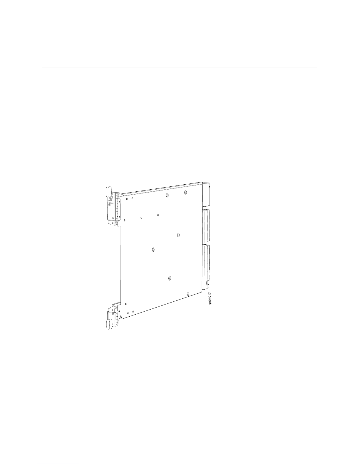
When the SCB is part of a host subsystem, the Routing Engine installs directly into
a slot on the SCB (see Figure 1 on page 2).
Figure 1: SCB
SCB Slots
You must install at least one SCB in the services gateway as part of a host subsystem.
The SCBs install into the front of the chassis in the slots labeled 0 and 1 on an SRX
5600 services gateway and 0, 1, and 2/6 on an SRX 5800 services gateway. If any
slots are empty, you must install a blank panel.
2 ■ Switch Control Board
Page 3

SCB Redundancy
If two SCBs are installed in an SRX 5600 services gateway, one SCB functions as the
master SCB and the other as its backup. If the master fails or is removed, the backup
becomes the master.
On SRX 5800 services gateways, SCBs installed in slots 0 and 1 provide nonredundant
fabric connections. A third installed SCB in slot 2/6 provides fabric redundancy but
no additional control or routing functions.
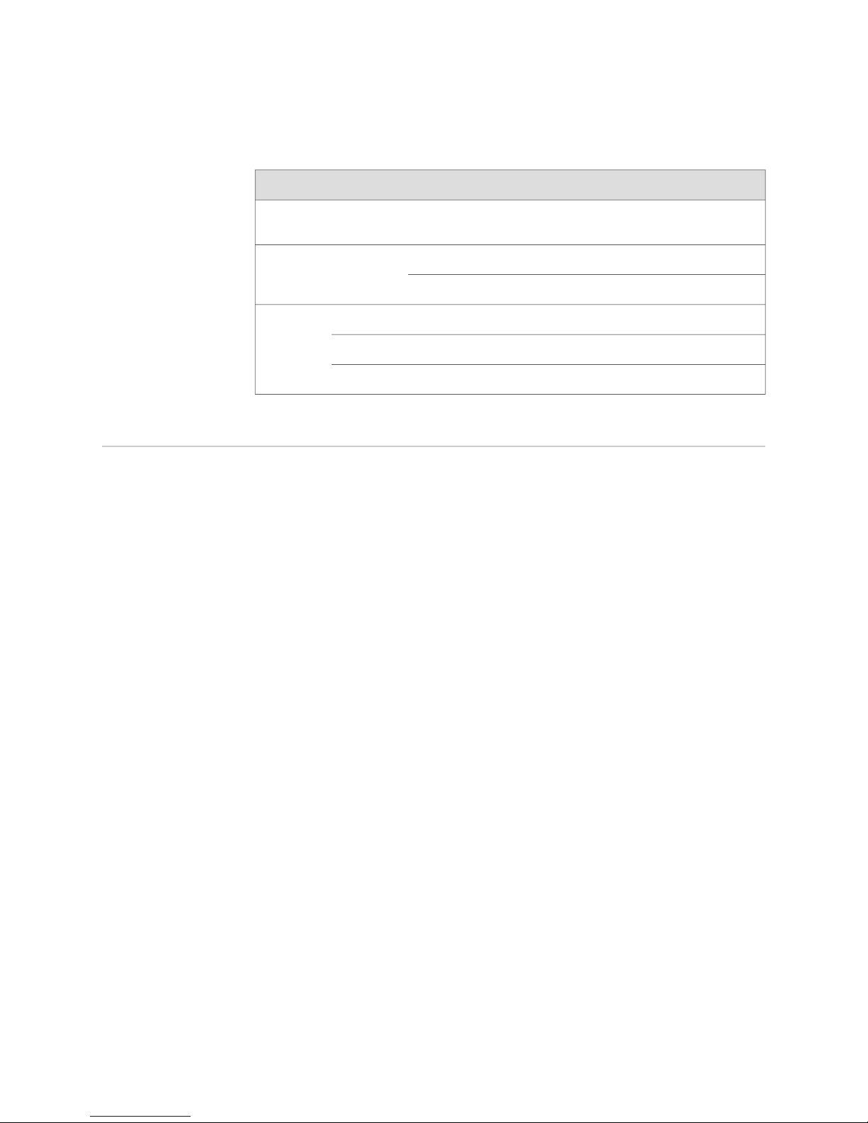
Table 1: SCB Slot Mapping and Functionality
Switch Control Board
SRX 5800 Services GatewaySRX 5600 Services GatewayFunctionality
Full fabric (nonredundant)
Redundant fabric
SCB Components
SCBs in slot 0 and slot 1SCB in slot 0
SCBs in slot 0, slot 1, and slot 2/6SCBs in slot 0 and slot 1
Each SCB consists of the following components:
■ Chassis management Ethernet switch.
■ I2C bus logic, used for low-level communication with each component.
■ Component redundancy circuitry.
■ Control Board/Routing Engine mastership mechanism.
■ Gigabit Ethernet switch that is connected to the embedded CPU complex on all
components.
■ Switch fabric—Provides the switching functions for the I/O cards (IOC)s.
■ Control FPGA—Provides the Peripheral Component Interconnect (PCI) interface
to the Routing Engine.
■ 1000Base-T Ethernet controller—Provides a 1-Gbps Ethernet link between the
Routing Engines.
■ Ethernet switch—Provides 1-Gbps link speeds between the Routing Engine and
the IOCs.
■ Circuits for chassis management and control.
■ Power circuits for the Routing Engine and SCB.
■ LEDs—Provide status (see “SCB LEDs” on page 3).
SCB LEDs
Three LEDs on the SCB indicate the status of the SCB. The LEDs, labeled FABRIC
ACTIVE, FABRIC ONLY, and OK/FAIL, are located directly on the SCB. Table 2 on page
4 describes the functions of the SCB LEDs.
Switch Control Board ■ 3
Page 4
SRX 5600 and SRX 5800 Services Gateway Switch Control Board Installation Instructions
Table 2: Switch Control Board LEDs
DescriptionStateColorLabel
Replacing an SCB
FABRIC
ACTIVE
FABRIC
ONLY
OK/FAIL
Fabric is in active mode.On steadilyGreen
SCB operates in fabric-only mode.On steadilyGreen
SCB operates in fabric/control board mode.Off
SCB is online.On steadilyGreen
SCB is offline.Off
SCB has failed.On steadilyRed
The services gateway can have up to three SCBs. They are located in the front of the
chassis in the slots marked 0 and 1 on an SRX 5600 services gateway and 0, 1, and
2/6 on an SRX 5800 services gateway. With a Routing Engine installed, the SCB
weighs approximately 9.6 lb (4.4 kg).
Before you replace an SCB or a Routing Engine, you must power off the services
gateway (see “Powering Off the Services Gateway” on page 4). To replace an SCB,
use the following procedures:
■ Powering Off the Services Gateway on page 4
■ Operating and Positioning the SCB Ejectors on page 5
■ Removing an SCB on page 5
■ Installing an SCB on page 6
Powering Off the Services Gateway
Before installing or removing SCBs you must power off the services gateway:
1. On the external management device connected to the Routing Engine, issue the
request system halt operational mode command. The command shuts down the
Routing Engine cleanly, so its state information is preserved.
Wait until a message appears on the console confirming that the operating system
has halted. For more information about the command, see the JUNOS System
Basics and Services Command Reference.
2. Attach an electrostatic discharge (ESD) grounding strap to your bare wrist and
connect the strap to one of the ESD points on the chassis. For more information
about ESD, see “Preventing Electrostatic Discharge Damage” on page 8.
4 ■ Replacing an SCB
user@host> request system halt
Page 5

3. On an AC-powered services gateway, switch the circuit breaker on each power
supply to the off position (O). On a DC-powered services gateway, switch the
circuit breaker on each power supply to the off position (OFF).
Operating and Positioning the SCB Ejectors
■ When removing or inserting an SCB, ensure that the SCBs or blank panels in
adjacent slots are fully inserted to avoid hitting them with the ejector handles.
The ejector handles require that all adjacent components be completely inserted
so the ejector handles do not hit them, which could result in damage.
■ The ejector handles have a center of rotation and need to be stored toward the
center of the board. Ensure the long ends of the ejectors located at both the top
and the bottom on an SRX 5800 services gateway, left and right on an SRX 5600
services gateway of the board are horizontal and pressed as far as possible
towards the center of the board.
■ To insert or remove the SCB, slide the ejector across the SCB horizontally, rotate
it, and slide it again another quarter of a turn. Turn the ejector again and repeat
as necessary. Utilize the indexing feature to maximize leverage and to avoid
hitting any adjacent components.
Replacing an SCB
Removing an SCB
■ Operate both ejector handles simultaneously. The insertion force on an SCB is
too great for one ejector.
To remove an SCB (see Figure 2 on page 6):
NOTE: The SCB and Routing Engine are removed as a unit. You can also remove the
Routing Engine separately.
1. Power off the device. See “Powering Off the Services Gateway” on page 4.
2. Place an electrostatic bag or antistatic mat on a flat, stable surface.
3. Attach an electrostatic discharge (ESD) grounding strap to your bare wrist and
connect the strap to one of the ESD points on the chassis. For more information
about ESD, see “Preventing Electrostatic Discharge Damage” on page 8.
4. Rotate the ejector handles simultaneously counterclockwise to unseat the SCB.
5. Grasp the ejector handles and slide the SCB about halfway out of the chassis.
6. Place one hand underneath the SCB to support it and slide it completely out of
the chassis.
7. Place the SCB on the antistatic mat.
8. If you are not replacing the SCB now, install a blank panel over the empty slot.
Replacing an SCB ■ 5
Page 6

SRX 5600 and SRX 5800 Services Gateway Switch Control Board Installation Instructions
Figure 2: Removing an SCB
Installing an SCB
To install an SCB (see Figure 3 on page 8):
1. Attach an electrostatic discharge (ESD) grounding strap to your bare wrist and
connect the strap to one of the ESD points on the chassis. For more information
about ESD, see “Preventing Electrostatic Discharge Damage” on page 8.
2. If you have not already done so, power off the device as described in “Powering
Off the Services Gateway” on page 4.
3. Carefully align the sides of the SCB with the guides inside the chassis.
4. Slide the SCB into the chassis until you feel resistance, carefully ensuring that it
is correctly aligned.
5. Grasp both ejector handles and rotate them simultaneously clockwise until the
SCB is fully seated.
6. Place the ejector handles in the proper position, horizontally and toward the
center of the board.
7.
Switch the circuit breaker or toggle switch for each power supply to the ON
position to start the device. The OK LED on the power supply faceplate should
blink, then light steadily.
6 ■ Replacing an SCB
Page 7

Replacing an SCB
For detailed instructions on powering-on the device see the SRX 5600 Services
Gateway Hardware Guide or the SRX 5800 Services Gateway Hardware Guide.
8. To verify that the SCB is functioning normally, check the LEDs on its faceplate.
The green OK/FAIL LED should light steadily a few minutes after the SCB is
installed. If the OK/FAIL LED is red, remove and install the SCB again (see
“Removing an SCB” on page 5 and “Installing an SCB” on page 6). If the
OK/FAIL LED still lights steadily, the SCB is not functioning properly. Contact
your customer support representative.
To check the status of the SCB:
user@host> show chassis environment cb
CB 0 status:
State Online Master
Temperature 30 degrees C / 86 degrees F
Power 1
1.2 V 1202 mV
1.5 V 1511 mV
1.8 V 1798 mV
2.5 V 2481 mV
3.3 V 3306 mV
5.0 V 4956 mV
12.0 V 12084 mV
1.25 V 1250 mV
3.3 V SM3 3287 mV
5.0 V RE 5046 mV
12.0 V RE 11910 mV
Power 2
11.3 V bias PEM 11292 mV
4.6 V bias MidPlane 4833 mV
11.3 V bias FPD 11156 mV
11.3 V bias POE 0 11253 mV
11.3 V bias POE 1 11272 mV
Bus Revision 42
FPGA Revision 1
CB 1 status:
State Online
Temperature 31 degrees C / 87 degrees F
Power 1
1.2 V 1205 mV
1.5 V 1508 mV
1.8 V 1817 mV
2.5 V 2507 mV
3.3 V 3306 mV
5.0 V 5053 mV
12.0 V 12200 mV
1.25 V 1256 mV
3.3 V SM3 3306 mV
5.0 V RE 5091 mV
12.0 V RE 0 mV
Power 2
11.3 V bias PEM 11214 mV
4.6 V bias MidPlane 4821 mV
11.3 V bias FPD 11350 mV
11.3 V bias POE 0 11350 mV
11.3 V bias POE 1 11330 mV
Bus Revision 42
FPGA Revision 0
Replacing an SCB ■ 7
Page 8

SRX 5600 and SRX 5800 Services Gateway Switch Control Board Installation Instructions
Figure 3: Installing an SCB
Preventing Electrostatic Discharge Damage
Many services gateway hardware components are sensitive to damage from static
electricity. Some components can be impaired by voltages as low as 30 V. You can
easily generate potentially damaging static voltages whenever you handle plastic or
foam packing material or if you move components across plastic or carpets. Observe
the following guidelines to minimize the potential for electrostatic discharge (ESD)
damage, which can cause intermittent or complete component failures:
■ Always use an ESD wrist strap or ankle strap, and verify that it is in direct contact
with your skin.
CAUTION: For safety, periodically check the resistance value of the ESD strap. The
measurement should be in the range of 1 to 10 Mohms.
■ When handling any component that has been removed from the chassis, verify
that the equipment end of your ESD strap is attached to one of the ESD points
on the chassis, which are shown in Figure 5 on page 9, and Figure 6 on page 10.
8 ■ Preventing Electrostatic Discharge Damage
Page 9

Electrostatic Discharge Point
■ Avoid contact between the component and your clothing. ESD voltages emitted
from clothing can still damage components.
■ When removing or installing a component, always place it component-side up
on an antistatic surface, in an antistatic card rack, or into an electrostatic bag
(see Figure 4 on page 9). If you are returning a component, place it into an
electrostatic bag before packing it.
Figure 4: Placing a Component into an Electrostatic Bag
Electrostatic Discharge Point
Figure 5 on page 9 and Figure 6 on page 10 show the location of the ESD point on
the front of each chassis.
Figure 5: Front View of a Fully Configured SRX 5600 Services Gateway Chassis
Electrostatic Discharge Point ■ 9
Page 10

SRX 5600 and SRX 5800 Services Gateway Switch Control Board Installation Instructions
Figure 6: Front View of a Fully Configured SRX 5800 Services Gateway Chassis
List of Technical Publications
Table 3 on page 10 lists the hardware guides and release notes for Juniper Networks
SRX–series services gateways and describes the contents of each document. All
documents are available at http://www.juniper.net/techpubs/.
Table 3: Technical Documentation for Supported Devices
DescriptionBook
Hardware Documentation
SRX 5600 Services Gateway Hardware Guide or
SRX 5800 Services Gateway Hardware Guide
Release Notes
10 ■ List of Technical Publications
Describes how to install, maintain, and troubleshoot the services
gateway and components. Each services gateway type has its own
hardware guide.
Page 11

Table 3: Technical Documentation for Supported Devices (continued)
DescriptionBook
Requesting Technical Support
JUNOS Software for SRX-series Services Gateway
Release Notes
Requesting Technical Support
Technical product support is available through the Juniper Networks Technical
Assistance Center (JTAC). If you are a customer with an active J-Care or JNASC support
contract, or are covered under warranty, and need postsales technical support, you
can access our tools and resources online or open a case with JTAC.
■ JTAC policies—For a complete understanding of our JTAC procedures and policies,
review the JTAC User Guide located at
http://www.juniper.net/customers/support/downloads/710059.pdf.
■ Product warranties—For product warranty information, visit
http://www.juniper.net/support/warranty/.
■ JTAC Hours of Operation —The JTAC centers have resources available 24 hours
a day, 7 days a week, 365 days a year.
Self-Help Online Tools and Resources
For quick and easy problem resolution, Juniper Networks has designed an online
self-service portal called the Customer Support Center (CSC) that provides you with
the following features:
Summarizes new features and known problems for a particular
release of JUNOS software on SRX-series services gateways,
including J-Web interface features and problems. The release notes
also contain corrections and updates to the manuals and software
upgrade and downgrade.
■
Find CSC offerings: http://www.juniper.net/customers/support/
■
Search for known bugs: http://www2.juniper.net/kb/
■
Find product documentation: http://www.juniper.net/techpubs/
■ Find solutions and answer questions using our Knowledge Base:
http://kb.juniper.net/
■ Download the latest versions of software and review release notes:
http://www.juniper.net/customers/csc/software/
■ Search technical bulletins for relevant hardware and software notifications:
https://www.juniper.net/alerts/
■ Join and participate in the Juniper Networks Community Forum:
http://www.juniper.net/company/communities/
■
Open a case online in the CSC Case Management tool: http://www.juniper.net/cm/
To verify service entitlement by product serial number, use our Serial Number
Entitlement (SNE) Tool located at https://tools.juniper.net/SerialNumberEntitlementSearch/.
Opening a Case with JTAC
Requesting Technical Support ■ 11
Page 12

SRX 5600 and SRX 5800 Services Gateway Switch Control Board Installation Instructions
You can open a case with JTAC on the Web or by telephone.
■
Use the Case Management tool in the CSC at http://www.juniper.net/cm/ .
■ Call 1-888-314-JTAC (1-888-314-5822 toll-free in the USA, Canada, and Mexico).
For international or direct-dial options in countries without toll-free numbers, visit
us at http://www.juniper.net/support/requesting-support.html.
Revision History
August 2008—530-026269-01 Revision 01 Initial release.
Copyright © 2009, Juniper Networks, Inc. All rights reserved.
Juniper Networks, the Juniper Networks logo, JUNOS, NetScreen, ScreenOS, and Steel-Belted Radius are registered trademarks of Juniper Networks, Inc. in
the United States and other countries. JUNOSe is a trademark of Juniper Networks, Inc. All other trademarks, service marks, registered trademarks, or
registered service marks are the property of their respective owners.
Juniper Networks assumes no responsibility for any inaccuracies in this document. Juniper Networks reserves the right to change, modify, transfer, or
otherwise revise this publication without notice.
Products made or sold by Juniper Networks or components thereof might be covered by one or more of the following patents that are owned by or licensed
to Juniper Networks: U.S. Patent Nos. 5,473,599, 5,905,725, 5,909,440, 6,192,051, 6,333,650, 6,359,479, 6,406,312, 6,429,706, 6,459,579, 6,493,347,
6,538,518, 6,538,899, 6,552,918, 6,567,902, 6,578,186, and 6,590,785.
12 ■ Requesting Technical Support
 Loading...