

Page 1

QFX5220 Switch Hardware Guide
Published
2021-02-22
Page 2

Juniper Networks, Inc.
1133 Innovation Way
Sunnyvale, California 94089
USA
408-745-2000
www.juniper.net
Juniper Networks, the Juniper Networks logo, Juniper, and Junos are registered trademarks of Juniper Networks, Inc. in
the United States and other countries. All other trademarks, service marks, registered marks, or registered service marks
are the property of their respective owners.
Juniper Networks assumes no responsibility for any inaccuracies in this document. Juniper Networks reserves the right
to change, modify, transfer, or otherwise revise this publication without notice.
QFX5220 Switch Hardware Guide
Copyright © 2021 Juniper Networks, Inc. All rights reserved.
The information in this document is current as of the date on the title page.
ii
YEAR 2000 NOTICE
Juniper Networks hardware and software products are Year 2000 compliant. Junos OS has no known time-related
limitations through the year 2038. However, the NTP application is known to have some difficulty in the year 2036.
END USER LICENSE AGREEMENT
The Juniper Networks product that is the subject of this technical documentation consists of (or is intended for use with)
Juniper Networkssoftware. Use ofsuch software is subjectto the termsand conditions ofthe End User LicenseAgreement
(“EULA”) posted at https://support.juniper.net/support/eula/. By downloading, installing or using such software, you
agree to the terms and conditions of that EULA.
Page 3

Table of Contents
1
About the Documentation | x
Documentation and Release Notes | x
Using the Examples in This Manual | x
Merging a Full Example | xi
Merging a Snippet | xii
Documentation Conventions | xii
Documentation Feedback | xv
Requesting Technical Support | xv
Self-Help Online Tools and Resources | xvi
Creating a Service Request with JTAC | xvi
iii
Overview
QFX5220 System Overview | 18
QFX5220-128C Switch Description | 18
Benefits of the QFX5220-128C | 19
QFX5220-32CD Switch Description | 20
Benefits of the QFX5220-32CD | 20
QFX5220 Hardware Component Overview | 21
System Software | 22
QFX5220 Component Redundancy | 22
QFX5220 Field-Replaceable Units | 23
QFX5220-32CD Port Panel | 24
Network Ports | 25
Setting Port Speed and Channelization | 25
QFX5220-32CD Network LEDs | 27
QFX5220-128C Port Panel | 29
Overview | 29
Network Ports | 30
Port Configurations | 31
100-Gbps Port Configuration | 44
Page 4

40-Gbps Port Configuration | 45
4 x 25 Gbps Port Channelization | 45
Delete 4 x 25 Gbps or 4 x 10 Gbps Port Channelization | 46
QFX5220-128C Network LEDs | 46
QFX5220 Management Panel | 48
QFX5220-128C Management Panel Overview | 49
QFX5220-32CD Management Panel Overview | 49
QFX5220-32CD Management Panel LEDs | 50
QFX5220 Chassis Status LEDs | 51
RJ-45 Management Port LEDs | 54
QFX5220 Cooling System | 55
QFX5220-128C Cooling System Description | 55
Fan Modules | 55
iv
QFX5220-128C Fan Module LED | 57
QFX5220-32CD Cooling System Description | 57
Fan Modules | 58
Do Not Install Components with Different Airflow or Wattage in the Switch | 60
QFX5220-32CD Fan Module LED | 61
Fan Module Status | 62
QFX5220 Power System | 64
QFX5220 AC Power Supply Modules Description | 66
QFX5220 AC Power Specifications | 68
AC Power Cord with Type C13 Coupler Specifications | 69
AC Power Cord with Type C15 Coupler Specifications | 71
QFX5220 AC Power Supply LEDs | 73
QFX5220 DC Power Supply Description | 74
QFX5220 DC Power Specifications | 76
QFX5220-128C DC Power Cable Specification | 77
QFX5220-128C DC Power Supply LED | 78
QFX5220-32CD-D DC Power Supply LED | 79
Page 5

Site Planning, Preparation, and Specifications
2
QFX5220 Site Preparation Checklist | 82
QFX5220 Site Guidelines and Requirements | 83
QFX5220 Environmental Requirements and Specifications | 84
General Site Guidelines | 85
QFX5220 Grounding Cable and Lug Specifications | 86
QFX5220 Clearance Requirements for Airflow and Hardware Maintenance | 87
QFX5220 Chassis Physical Specifications | 88
Site Electrical Wiring Guidelines | 88
QFX5220 Rack Requirements | 89
QFX5220 Cabinet Requirements | 90
QFX5220 Network Cable and Transceiver Planning | 92
v
Determining QFX5220 Optical Interface Support | 92
Cable Specifications for QSFP+ and QSFP28 Transceivers | 93
Understanding QFX Series Fiber-Optic Cable Signal Loss, Attenuation, and Dispersion | 95
Signal Loss in Multimode and Single-Mode Fiber-Optic Cables | 95
Attenuation and Dispersion in Fiber-Optic Cable | 95
Calculating Power Budget and Power Margin for Fiber-Optic Cables | 96
How to Calculate Power Budget for Fiber-Optic Cable | 97
How to Calculate Power Margin for Fiber-Optic Cable | 97
QFX5220 Management Cable Specifications and Pinouts | 99
Cable Specifications for Console and Management Connections for the QFX Series | 99
RJ-45 Management Port Connector Pinout Information | 100
Console Port Connector Pinouts for the QFX Series | 100
QSFP-DD Port Connector Pinout Information | 101
QSFP+, QSFP28, and QSFP56 Port Connector Pinout Information | 105
SFP, SFP+, and SFP28 Port Connector Pinout Information | 107
USB Port Specifications for the QFX Series | 108
Page 6

Initial Installation and Configuration
3
QFX5220 Installation Overview | 111
Overview of Installing the QFX5220 | 111
QFX5220 Installation Safety Guidelines | 112
Unpacking and Mounting the QFX5220 | 112
Unpacking a QFX5220 | 113
Register Products—Mandatory to Validate SLAs | 115
Mounting a QFX5220 in a Rack or Cabinet | 116
Before You Begin Rack Installation | 117
Four-Post Installation Procedure for QFX5220-128C | 118
Four-Post Installation Procedure for QFX5220-32CD | 120
Four-Post Cabinet Installation for QFX5220-32CD | 122
EMI Panel Installation on QFX5220-128C | 125
vi
Connecting the QFX5220 to External Devices | 128
Ground the QFX5220-128C | 129
Connect Power to the QFX5220-128C | 129
Ground the QFX5220-32CD and Connect Power | 132
Connect a Device to a Network for Out-of-Band Management | 133
Connect a Device to a Management Console Using an RJ-45 Connector | 134
Connecting the QFX5220 to Power | 136
How to Connect AC Power to a QFX5220 | 136
How to Connect DC Power to a QFX5220-128C | 139
How to Connect DC Power to a QFX5220-32CD-D | 142
Before You Begin | 142
Connecting DC Power to a QFX5220-32CD-D | 143
Performing the Initial Software Configuration for QFX5220 Switches | 147
Page 7

Maintaining Components
4
5
6
Maintaining QFX5220 Cooling System | 151
How to Remove a Fan Module from a QFX5220 | 151
How to Remove a Fan Module in a QFX5220 | 153
Maintaining the QFX5220 Power System | 155
How to Remove a Power Supply from a QFX5220 | 155
How to Install an AC Power Supply in a QFX5220 | 158
Maintaining Transceivers and Fiber Optic Cables on a QFX5220 | 161
Remove a Transceiver | 161
Install a Transceiver | 164
Disconnect a Fiber-Optic Cable | 166
Connect a Fiber-Optic Cable | 167
vii
How to Handle Fiber-Optic Cables | 168
Powering Off a QFX5220 | 169
Removing the EMI Panel from QFX5220-128C | 171
Troubleshooting Hardware
Troubleshooting the QFX5220 | 175
QFX5220 Troubleshooting Resources Overview | 175
QFX5220 Alarm Messages Overview | 176
Chassis Alarm Messages | 177
Configuration Changes Leading to Unexpected QFX5220 Behavior | 179
How to Troubleshoot QFX5220-128C Port Configuration Problems | 180
How to Troubleshoot QFX5220-128C Channelization Problems | 181
Contacting Customer Support and Returning the Chassis or Components
Contact Customer Support to Obtain Return Material Authorization | 184
Returning the QFX5220 Chassis or Components | 185
Locating the Serial Number on a QFX5220 Device or Component | 185
Listing the Chassis and Component Details Using the CLI | 186
Locating the Chassis Serial Number ID Label on a QFX5220 | 187
Page 8

Locating the Serial Number ID Labels on FRU Components | 188
7
Removing the Solid-State Drives for RMA | 190
How to Return a Hardware Component to Juniper Networks, Inc. | 193
Guidelines for Packing Hardware Components for Shipment | 194
Packing a QFX5220 Device or Component for Shipping | 194
Packing a QFX5220 Switch for Shipping | 195
Packing QFX5220 Components for Shipping | 196
Safety and Compliance Information
General Safety Guidelines and Warnings | 199
Definitions of Safety Warning Levels | 200
Qualified Personnel Warning | 203
Warning Statement for Norway and Sweden | 204
viii
Fire Safety Requirements | 204
Fire Suppression | 204
Fire Suppression Equipment | 204
Installation Instructions Warning | 206
QFX5220 Installation Safety Guidelines | 206
Restricted Access Warning | 208
Ramp Warning | 210
Rack-Mounting and Cabinet-Mounting Warnings | 211
Grounded Equipment Warning | 217
Laser and LED Safety Guidelines and Warnings | 218
General Laser Safety Guidelines | 218
Class 1 Laser Product Warning | 219
Class 1 LED Product Warning | 220
Laser Beam Warning | 221
Page 9

Radiation from Open Port Apertures Warning | 222
Maintenance and Operational Safety Guidelines and Warnings | 223
Battery Handling Warning | 224
Jewelry Removal Warning | 225
Lightning Activity Warning | 227
Operating Temperature Warning | 228
Product Disposal Warning | 230
General Electrical Safety Guidelines and Warnings | 231
Action to Take After an Electrical Accident | 232
Prevention of Electrostatic Discharge Damage | 233
AC Power Electrical Safety Guidelines | 234
ix
AC Power Disconnection Warning | 236
DC Power Electrical Safety Guidelines | 237
DC Power Copper Conductors Warning | 238
DC Power Disconnection Warning | 239
DC Power Grounding Requirements and Warning | 241
DC Power Wiring Sequence Warning | 243
DC Power Wiring Terminations Warning | 246
Multiple Power Supplies Disconnection Warning | 249
TN Power Warning | 250
Agency Approvals and Compliance Statements for the QFX5200 and QFX5220 | 250
Agency Approvals for the QFX Series | 251
Page 10
About the Documentation
IN THIS SECTION
Documentation and Release Notes | x
Using the Examples in This Manual | x
Documentation Conventions | xii
Documentation Feedback | xv
Requesting Technical Support | xv
Use this guide to plan, install, perform initial software configuration, perform routine maintenance, and to
troubleshoot QFX5220 switches.
x
After completing the installation and basic configuration procedures covered in this guide, refer to the
Junos OS documentation for further software configuration.
Documentation and Release Notes
To obtain the most current version of all Juniper Networks®technical documentation, see the product
documentation page on the Juniper Networks website at https://www.juniper.net/documentation/.
If the information in the latest release notes differs from the information in the documentation, follow the
product Release Notes.
Juniper Networks Books publishes books by Juniper Networks engineers and subject matter experts.
These books go beyond the technical documentation to explore the nuances of network architecture,
deployment, and administration. The current list can be viewed at https://www.juniper.net/books.
Using the Examples in This Manual
If you want to use the examples in this manual, you can use the load merge or the load merge relative
command. These commands cause the software to merge the incoming configuration into the current
candidate configuration.The example does not become active untilyou commit the candidate configuration.
Page 11

If the example configuration contains the top level of the hierarchy (or multiple hierarchies), the example
is a full example. In this case, use the load merge command.
If the example configuration does not start at the top level of the hierarchy, the example is a snippet. In
this case,use the load merge relative command. These procedures aredescribed in the following sections.
Merging a Full Example
To merge a full example, follow these steps:
1. From the HTML or PDF version of the manual, copy a configuration example into a text file, save the
file with a name, and copy the file to a directory on your routing platform.
For example, copy the following configuration to a file and name the file ex-script.conf. Copy the
ex-script.conf file to the /var/tmp directory on your routing platform.
system {
scripts {
commit {
file ex-script.xsl;
}
}
}
interfaces {
fxp0 {
disable;
unit 0 {
family inet {
address 10.0.0.1/24;
}
}
}
}
xi
2. Merge the contents of the file into your routing platform configuration by issuing the load merge
configuration mode command:
[edit]
user@host# load merge /var/tmp/ex-script.conf
load complete
Page 12

Merging a Snippet
To merge a snippet, follow these steps:
1. From the HTML or PDF version of the manual, copy a configuration snippet into a text file, save the
file with a name, and copy the file to a directory on your routing platform.
For example, copy the following snippet to a file and name the file ex-script-snippet.conf. Copy the
ex-script-snippet.conf file to the /var/tmp directory on your routing platform.
commit {
file ex-script-snippet.xsl; }
2. Move to the hierarchy level that is relevant for this snippet by issuingthe following configuration mode
command:
[edit]
user@host# edit system scripts
[edit system scripts]
xii
3. Merge the contents of the file into your routing platform configuration by issuing the load merge
relative configuration mode command:
[edit system scripts]
user@host# load merge relative /var/tmp/ex-script-snippet.conf
load complete
For more information about the load command, see CLI Explorer.
Documentation Conventions
Table 1 on page xiii defines notice icons used in this guide.
Page 13
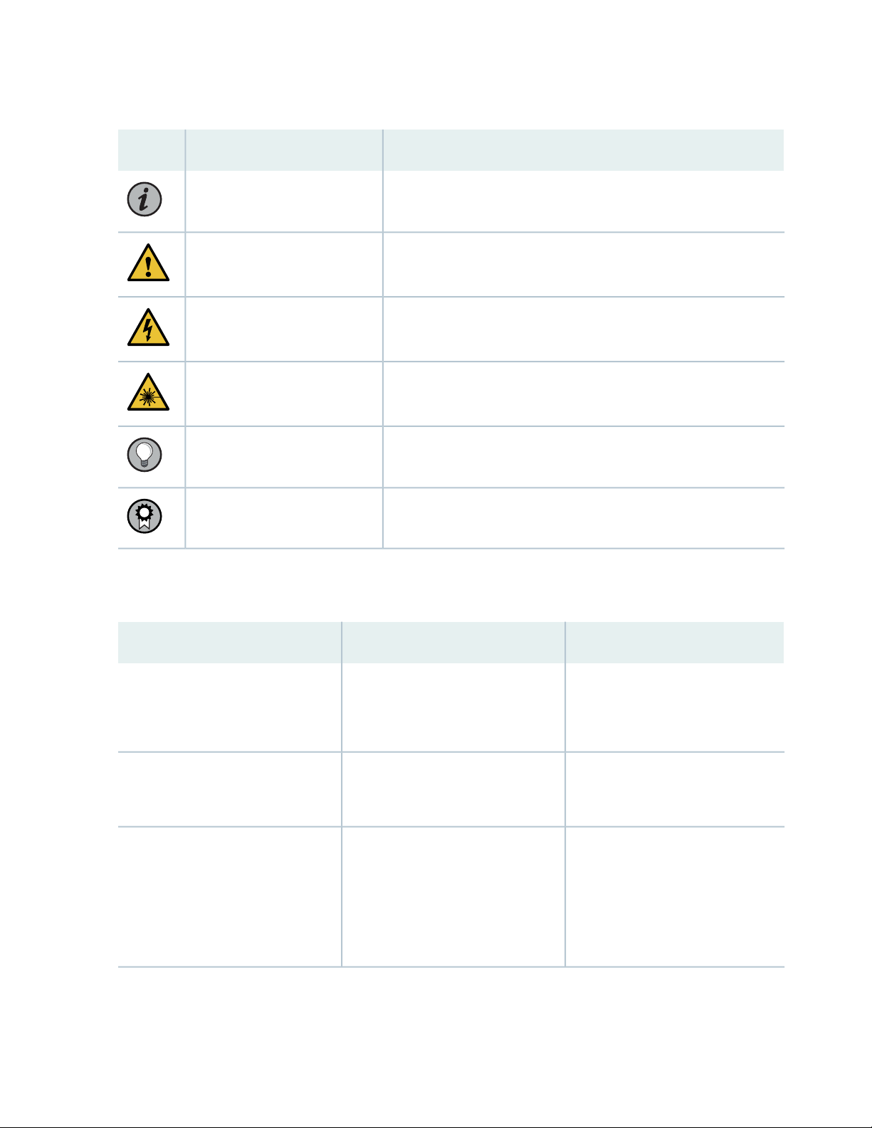
Table 1: Notice Icons
xiii
DescriptionMeaningIcon
Indicates important features or instructions.Informational note
Caution
Indicates a situation that might result in loss of data or hardware
damage.
Alerts you to the risk of personal injury or death.Warning
Alerts you to the risk of personal injury from a laser.Laser warning
Indicates helpful information.Tip
Alerts you to a recommended use or implementation.Best practice
Table 2 on page xiii defines the text and syntax conventions used in this guide.
Table 2: Text and Syntax Conventions
ExamplesDescriptionConvention
Fixed-width text like this
Italic text like this
Represents text that you type.Bold text like this
Represents output that appears on
the terminal screen.
Introduces oremphasizes important
•
new terms.
Identifies guide names.
•
Identifies RFC and Internet draft
•
titles.
To enter configuration mode, type
the configure command:
user@host> configure
user@host> show chassis alarms
No alarms currently active
A policy term is a named structure
•
that defines match conditions and
actions.
Junos OS CLI User Guide
•
RFC 1997, BGP Communities
•
Attribute
Page 14

Table 2: Text and Syntax Conventions (continued)
xiv
ExamplesDescriptionConvention
Italic text like this
Text like this
< > (angle brackets)
| (pipe symbol)
Represents variables (options for
which you substitute a value) in
commands or configuration
statements.
Represents names of configuration
statements, commands, files, and
directories; configuration hierarchy
levels; or labels on routing platform
components.
variables.
Indicates a choice between the
mutually exclusive keywords or
variables on either side of the symbol.
The set of choices is often enclosed
in parentheses for clarity.
Configure the machine’s domain
name:
[edit]
root@# set system domain-name
domain-name
To configure a stub area, include
•
the stub statement at the [edit
protocols ospf area area-id]
hierarchy level.
The console port is labeled
•
CONSOLE.
stub <default-metric metric>;Encloses optional keywords or
broadcast | multicast
(string1 | string2 | string3)
# (pound sign)
[ ] (square brackets)
Indention and braces ( { } )
; (semicolon)
GUI Conventions
Indicates a comment specified on the
same line as the configuration
statement to which it applies.
Encloses a variable for which you can
substitute one or more values.
Identifies a level in the configuration
hierarchy.
Identifies a leaf statement at a
configuration hierarchy level.
rsvp { # Required for dynamic MPLS
only
community name members [
community-ids ]
[edit]
routing-options {
static {
route default {
nexthop address;
retain;
}
}
}
Page 15

Table 2: Text and Syntax Conventions (continued)
xv
ExamplesDescriptionConvention
Bold text like this
> (bold right angle bracket)
Represents graphical user interface
(GUI) items you click or select.
Separates levels in a hierarchy of
menu selections.
In the Logical Interfaces box, select
•
All Interfaces.
To cancel the configuration, click
•
Cancel.
In the configuration editor hierarchy,
select Protocols>Ospf.
Documentation Feedback
We encourage you to provide feedback so that we can improve our documentation. You can use either
of the following methods:
Online feedback system—Click TechLibrary Feedback, on the lower right of any page on the Juniper
•
Networks TechLibrary site, and do one of the following:
Click the thumbs-up icon if the information on the page was helpful to you.
•
Click the thumbs-down icon if the information on the page was not helpful to you or if you have
•
suggestions for improvement, and use the pop-up form to provide feedback.
E-mail—Send yourcomments to techpubs-comments@juniper.net. Include the document or topic name,
•
URL or page number, and software version (if applicable).
Requesting Technical Support
Technical product support is available through the Juniper Networks Technical Assistance Center (JTAC).
If you are a customer with an active Juniper Care or Partner Support Services support contract, or are
Page 16

covered under warranty, and need post-sales technical support, you can access our tools and resources
online or open a case with JTAC.
JTAC policies—Fora complete understanding of our JTAC procedures andpolicies, review the JTAC User
•
Guide located at https://www.juniper.net/us/en/local/pdf/resource-guides/7100059-en.pdf.
Product warranties—Forproduct warranty information, visit https://www.juniper.net/support/warranty/.
•
JTAC hours of operation—The JTAC centers have resources available 24 hours a day, 7 days a week,
•
365 days a year.
Self-Help Online Tools and Resources
For quick and easy problem resolution, Juniper Networks has designed an online self-service portal called
the Customer Support Center (CSC) that provides you with the following features:
Find CSC offerings: https://www.juniper.net/customers/support/
•
Search for known bugs: https://prsearch.juniper.net/
•
xvi
Find product documentation: https://www.juniper.net/documentation/
•
Find solutions and answer questions using our Knowledge Base: https://kb.juniper.net/
•
Download the latest versions of software and review release notes:
•
https://www.juniper.net/customers/csc/software/
Search technical bulletins for relevant hardware and software notifications:
•
https://kb.juniper.net/InfoCenter/
Join and participate in the Juniper Networks Community Forum:
•
https://www.juniper.net/company/communities/
Create a service request online: https://myjuniper.juniper.net
•
To verify service entitlement by product serial number, use our Serial Number Entitlement (SNE) Tool:
https://entitlementsearch.juniper.net/entitlementsearch/
Creating a Service Request with JTAC
You can create a service request with JTAC on the Web or by telephone.
Visit https://myjuniper.juniper.net.
•
Call 1-888-314-JTAC (1-888-314-5822 toll-free in the USA, Canada, and Mexico).
•
For international or direct-dial options in countries without toll-free numbers, see
https://support.juniper.net/support/requesting-support/.
Page 17

1
CHAPTER
Overview
QFX5220 System Overview | 18
QFX5220-32CD Port Panel | 24
QFX5220-128C Port Panel | 29
QFX5220 Management Panel | 48
QFX5220 Cooling System | 55
QFX5220 Power System | 64
Page 18

QFX5220 System Overview
IN THIS SECTION
QFX5220-128C Switch Description | 18
Benefits of the QFX5220-128C | 19
QFX5220-32CD Switch Description | 20
Benefits of the QFX5220-32CD | 20
QFX5220 Hardware Component Overview | 21
System Software | 22
QFX5220 Component Redundancy | 22
QFX5220 Field-Replaceable Units | 23
18
The QFX5220 line of switches offer two models for environments requiring 100-Gigabit Ethernet and
400-Gigabit Ethernet speeds.
QFX5220-128C Switch Description
The QFX5220-128C offers 128 ports of 100-Gigabit Ethernet in a 4-U form factor. With 12.8 terabits per
second (Tbps)bandwidth, the QFX5220-128C is an optimal choicefor spine-and-leaf IP fabric deployments
as well as metro use cases. The 100-Gigabit Ethernet ports can be configured either for 100-Gbps or
40-Gbps speeds. The 100-Gbps ports can also be channelized into 4 x 25 Gbps or 4 x 10 Gbps. There are
two dedicated small-form factor plugable plus (SFP+) ports for 10 Gigabit or 1 Gigabit Ethernet support.
An Intel Xeon D-1518 processor drives the QFX5220 control plane, which runs the Junos OS Evolved
software. The Junos OS Evolved software image is stored on two internal 50-GB solid-state drives (SSDs).
The QFX5220-128C is available with ports-to-FRUs airflow (Airflow Out) and with AC or DC power
supplies.
Page 19
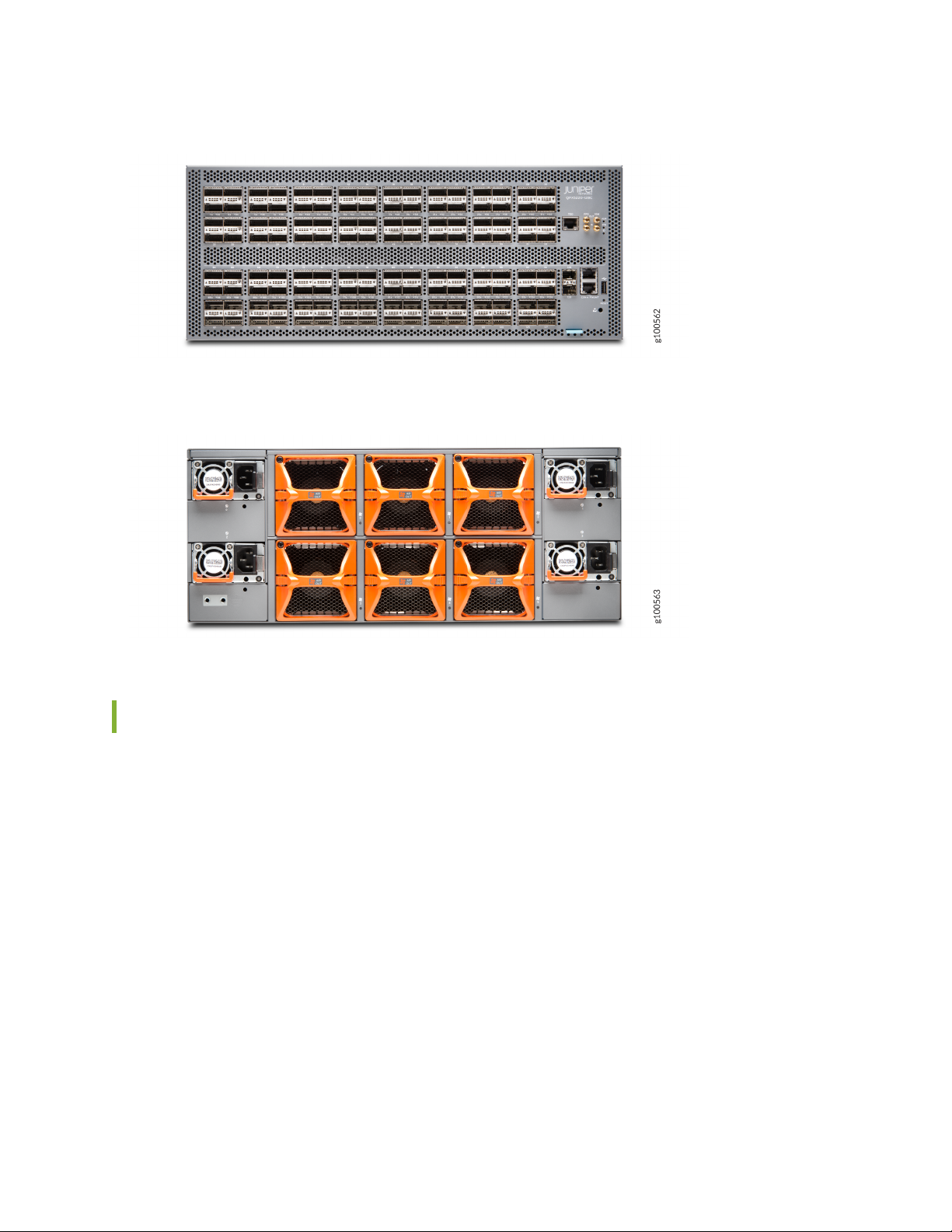
Figure 1: QFX5220-128C Front Panel
Figure 2: QFX5220-128C FRU Panel
19
Benefits of the QFX5220-128C
Serves thespine layer needs of a wide rangeof enterprises. Examples include: cloud and high-performance
•
computing data centers; Software as a Service (SaaS) providers; streaming video service providers; cable
operators; financial service providers and enterprises that run large-scale Web applications, analytics,
and deep learning workloads.
Serves as a DC edge or DCI platform for metro MPLS use cases.
•
Supports IEEE 1588 Precision Time Protocol (PTP), Transparent Clock, and hardware timestamping for
•
distributing precise time and frequency over packet networks. PTP is an important prerequisite in
real-time sensitive workloads such as those employed in financial trading, real-time video streaming,
and broadcasting networks.
Aligns well with the needs of environments whose aggregate traffic comprises lossless classes of traffic
•
such as access toa remote flash storage, support for advanced congestion control, and flow-awaretraffic
scheduling support.
Page 20
Supports zero touch provisioning at the ports, which automates provisioning and deployment with
•
minimal manual intervention, saving time and effort for network operators.
Provides improved power efficiency and lowered costs per 100-Gigabit Ethernet port making this the
•
industry best-in-class solution to support ever-expanding bandwidth needs.
QFX5220-32CD Switch Description
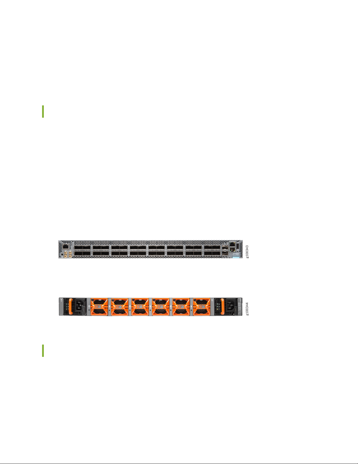
The QFX5220-32CD offers 32 ports of 400-Gigabit Ethernet in a low-profile 1-U form factor. With
12.8-Tbps bandwidth,the QFX5220-32CD is an optimalchoice for very large, dense, and fastspine-and-leaf
IP fabric deployments, as well as metro use cases. The high-speed ports support a wide variety of port
configurations that include speeds of 400 Gbps, 100 Gbps, 25 Gbps, 40 Gbps, and 10 Gbps.
An Intel Xeon D-1500 processor drives the QFX5220 control plane, which runs the Junos OS Evolved
software. The Junos OS Evolved software image is stored on two internal 50-GB solid-state drives (SSDs).
20
The QFX5220-32CD is available with either ports-to-FRUs or FRUs-to-ports airflow and with AC or DC
power supplies. See Figure 3 on page 20 and Figure 4 on page 20.
Figure 3: Front Panel View of the QFX5220-32CD
Figure 4: FRU Panel View of the QFX5220-32CD
Benefits of the QFX5220-32CD
Reduces compute-intensive workloads for hyperscale cloud and high-performance computing (HPC)
•
data centers.Examples of these compute-intensive workloads include AI, machine learning,deep learning
applications, and storage disaggregation workloads such as Non-Volatile Express over Fabrics (NVMe
over Fabrics).
Enables data center re-architecture with flattened pods that slash switch hop latency.
•
Page 21

Serves as a DC edge or DCI platform for metro MPLS use cases.
•
Enables a fast response by demanding applications, such as those encountered in financial exchanges
•
by reducing intracluster switch latency.
Allows current Junos OS users to seamlessly migrate to Junos OS Evolved Linux software. With Junos
•
OS Evolved, you can run Linux using your familiar Junos OS CLI, and run third-party Linux applications
with Juniper Extension Toolkit (JET) API support, telemetry support formonitoring the DC network, and
support for module-level in-service software upgrade (ISSU).
Saves you energy costs by highly reducing power consumption per Gbps of network traffic passing
•
through the switch.
Provides an extensive roadmap to new features and functions, such as:
•
Advanced Precision Time Protocol (PTP) support (enhanced mirroring with PTP) for running real-time
•
analytics on network flows
Comprehensive Remote Direct Memory Access over Converged Ethernet version 2 (RoCEv2)
•
Advanced congestion control and flow-aware traffic scheduling
•
21
Support for container networking and segment routing
•
Scale-out load balancing and multipathing
•
Support for advanced network instrumentation adopted by cloud data centers
•
QFX5220 Hardware Component Overview
The QFX5220 supports the components listed in Table 3 on page 21.
Table 3: QFX5220 Hardware Components
Chassis
Fan module
QFX5220-32CD
QFX5220-128C
QFX5220-32CD
QFX5220-128C
QFX5220-32CD-CHAS
QFX5220-128C-CHAS
QFX5220-32CD-FANAI (FRUs-to-ports
airflow)
QFX5220-32CD-FANAO (ports-to-FRUs
airflow)
CLI OutputSpare Juniper Model NumberChassis ModelComponent
QFX5220-32CD
QFX5220-128C
Fan tray n fan-n Back-to-front
airflow - AFI
NOTE: The QFX5220-128C is
not available in AFI airflow.
QFX5220-128C-FANAO
Fan tray n fan-n Front-to-back
airflow - AFO
Page 22

Table 3: QFX5220 Hardware Components (continued)
22
CLI OutputSpare Juniper Model NumberChassis ModelComponent
QFX5220-32CDPower supplies
QFX5220-128C-AFO
JPSU-1600W-1UACAFI (FRUs-to-ports
airflow)
JPSU-1600W-1UACAFO (ports-to-FRUs
airflow)
JPSU-1600W-1UDCAFI (FRUs-to-ports
airflow)
JPSU-1600W-1UDCAFO (ports-to-FRUs
airflow)
JPSU-1600W-AC-AFO
JPSU-1600W-DC-AFO
AC AFI 1600W PSU
AC AFO 1600W PSU
DC AFI 1600W PSU
DC AFO 1600W PSU
AC AFO 1600W PSU
NOTE: The QFX5220-128C is
not available in AFI airflow.
System Software
The Junos OS Evolved software on the QFX5220 provides Layer 2 and Layer 3 switching, routing, and
security services. Junos OS Evolved is installed on the switch solid-state drive (SSD).
For more information about which features are supported on QFX Series devices, see Feature Explorer.
You managethe switch using the JunosOS CLI, accessiblethrough the console and out-of-bandmanagement
ports on the device.
The QFX5220-32CD is supported on Junos OS Evolved Release 19.1R1 and later. The QFX5200-128C
is supported on Junos OS Evolved Release 19.2R1 and later.
The DC version, QFX5220-32CD-D, is supported on Junos OS Evolved Release 19.3R1 and later.
QFX5220 Component Redundancy
The following hardware components provide redundancy on a QFX5220 switch:
Page 23
QFX5220-32CD power supplies—The QFX5220-32CD switches have one or two power supplies. Each
•
power supply provides power to all components in the switch. If two power supplies are installed, the
two power supplies provide full power redundancy to the device. If one power supply fails or is removed,
the second power supply balances the electrical load without interruption.
To provide power redundancy to the system, both power supplies must be installed. Connect power
source feed A to one power supply and power source feed B to the second power supply.
CAUTION: Do not connect feed A and feed B to the same power supply input
terminal.
QFX5220-128C powersupply modules—The QFX5220-128Cswitches have two to fourpower supplies.
•
The power supply modules are used in 2 + 2 redundancy mode. The system can run on two power
supplies without redundancy. If one power supply failsor isremoved, the other power supplies balances
the electrical load without interruption.
QFX5220-32CD cooling system—The QFX5220-32CD switch models have six fan modules and can
•
operate with one fan not in operation (5+1 redundancy). If more than one fan module fails and is unable
to keep the QFX5220-32CD within the desired temperature thresholds, chassis alarms occur and the
QFX5220-32CD switch can shut down.
23
QFX5220-128C cooling system—This switch model has 12 fans in 6 fan modules. There is one fan out
•
of the 12 fans forredundancy. This isknown as (5x2+1)+1redundancy). Any additionalfan failures cause
the switch to overheat, chassis alarms to occur and shutdown the switch.
QFX5220 Field-Replaceable Units
Field-replaceable units (FRUs) are components that you can replace at your site. The QFX5220 device
FRUs are hot-insertable and hot-removable: you can remove and replace one of them without powering
off the switch or disrupting the switching function.
CAUTION: Replace a failed power supply with a new power supply within 3 minutes
of removal to prevent chassis overheating. The QFX5220-32CD switch continues to
operate with only one power supply running. The QFX5220-128C can operate with
only two power supplies running. For best performance, we advise replacing failed
power supplies and fan modules as quickly as possible to protect against another
failure.
Table 4 on page 24 lists the FRUs for the QFX5220 device and actions to take before removing them.
Page 24

Table 4: FRUs in a QFX5220 Switch
24
Required ActionFRU
None.Power supplies
None.Fan modules
Optical transceivers
NOTE: If you have a Juniper Care service contract, register any addition, change, or upgrade of
hardware componentsat https://www.juniper.net/customers/support/tools/updateinstallbase/.
Failure to do so can result in significant delays if you need replacement parts. This note does
not apply if you replace existing components with the same type of component.
RELATED DOCUMENTATION
QFX5220 Management Panel | 48
QFX5220 Cooling System | 55
QFX5220 Power System | 64
None. We recommend that you disable the interface using the set interfaces
interface-name disable command before you remove the transceiver. See
Disconnect a Fiber-Optic Cable.
QFX5220-32CD Port Panel
IN THIS SECTION
Network Ports | 25
Setting Port Speed and Channelization | 25
QFX5220-32CD Network LEDs | 27
Page 25
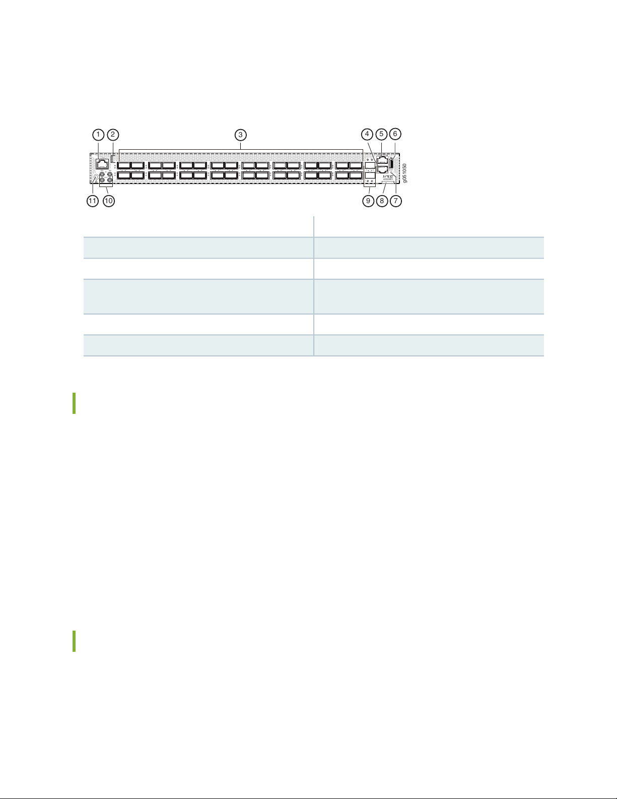
The port panel of the QFX5220-32CD has 32 high-speed ports that support transmission at 400-Gbps,
g051050
TOD
ALM
SYS
ID
10M
IN
OUT
PPS
10 3 54 76 8 110 1312 1514 1716 1918 2 120 2322 2524 2726 2928 3130 33322 9 1
RESET
MGMTCON
1 2
3
89
1011
54
7
6
100-Gbps, or 25-Gbps speeds. It also has 2 dedicated ports for 10 Gbps.
7—1— Reset button (do not use unless directed by JTAC)RJ-45 connection to grandmaster clock
8—2— Chassis serial number pull-outChassis status LEDs
9—3— 10 Gigabit Ethernet ports–SFP+ cages32 high-speed ports-QSFP-DD cages
25
RJ-45 management port (100 Mbps/1000 Mbps/
10000 Mbps)
10—4— Clock input and output connectors (10 MHz and 1
PPS)
11—5— ESD grounding pointRJ-45 console port
6—USB port (USB 2.0/3.0 standard)
Network Ports
The QFX5220-32CD network ports (0 to 31) support:
400-Gbps QSFP-DD direct attach copper (DAC) cables
•
400 Gbps active optic cable (AOC) (starting in Junos OS Evolved Release 19.3R2)
•
100-Gbps QSFP28 transceivers
•
100 Gbps active optic break outcables (AOCBO) QSFP28 to four SFP25G interfaces
•
40-Gbps QSFP+ to SFP+ DACBO cables (40-Gbps breaks out to 4 independent 10-Gbps
•
connections)–Junos OS Evolved Release 20.2R1 and later
The 10-Gbps network ports 32 and 33 support small form-factor plus (SFP+) transceivers.
Setting Port Speed and Channelization
The default port speed for ports 0 through 31 is 400 Gbps. Only QSFP-DD optics inserted in these ports
will link without configuration. See Table 5 on page 26.
Page 26

Table 5: QFX5220-32CD Port Speed Autodetection
Sets Default Speed toTransceiver, DAC, AOC, DACBO, or AOCBO
400 Gbps, link upQSFP-DD
400 Gbps, link downQSFP28
400 Gbps, link downQSFP
10 Gbps, link upSFP+ (ports 32 and 33 only) and management port
NOTE: The QFX5220-32CD does not support autonegotiation between devices.
If a port already has a speed configured, you can manually configure the ports. To set the speed, use the
set chassis fpc FPC number pic pic number port port number speed 25|40|100|200|400 configuration mode
CLI command. For example, to set port 2 to 100 Gbps:
26
[edit chassis]
user@host#set chassis fpc 0 pic 0 port 2 speed 100g
NOTE: On QFX5220-32CD devices, there is a single FPC and PIC, which is always 0.
After you set a port speed, you can channelize the port into 4 independent 25-Gigabit Ethernet interfaces
by configuring the number of subports and speed. You should use the set chassis fpc FPC number pic pic
number port port number number-of-sub-ports 1|2|3|4 command. For example, to configure 100-Gbps
port 4 to four independent 25-Gbps interfaces:
[edit chassis]
user@host#set chassis fpc 0 pic 0 port 4 speed 25g number-of-sub-ports 4
Be sure to save and commit your changes.
Page 27
WARNING: An incorrectly configured port can cause unexpected port and switch
g051096
2928 3130 333 2
Link/Activity
LED
Link/Activity
LED
Link/Activity
Status LEDs
Status
LED
Status
LED
behavior. The system software doesnot check whether the port speed or the attached
optic are supported at the time of the commit. Use the show chassis alarms and the
show chassis pic fpc-slot 0 pic-slot 0 to locate incorrectly configured ports. See
“Configuration Changes Leading to Unexpected QFX5220 Behavior” on page 179.
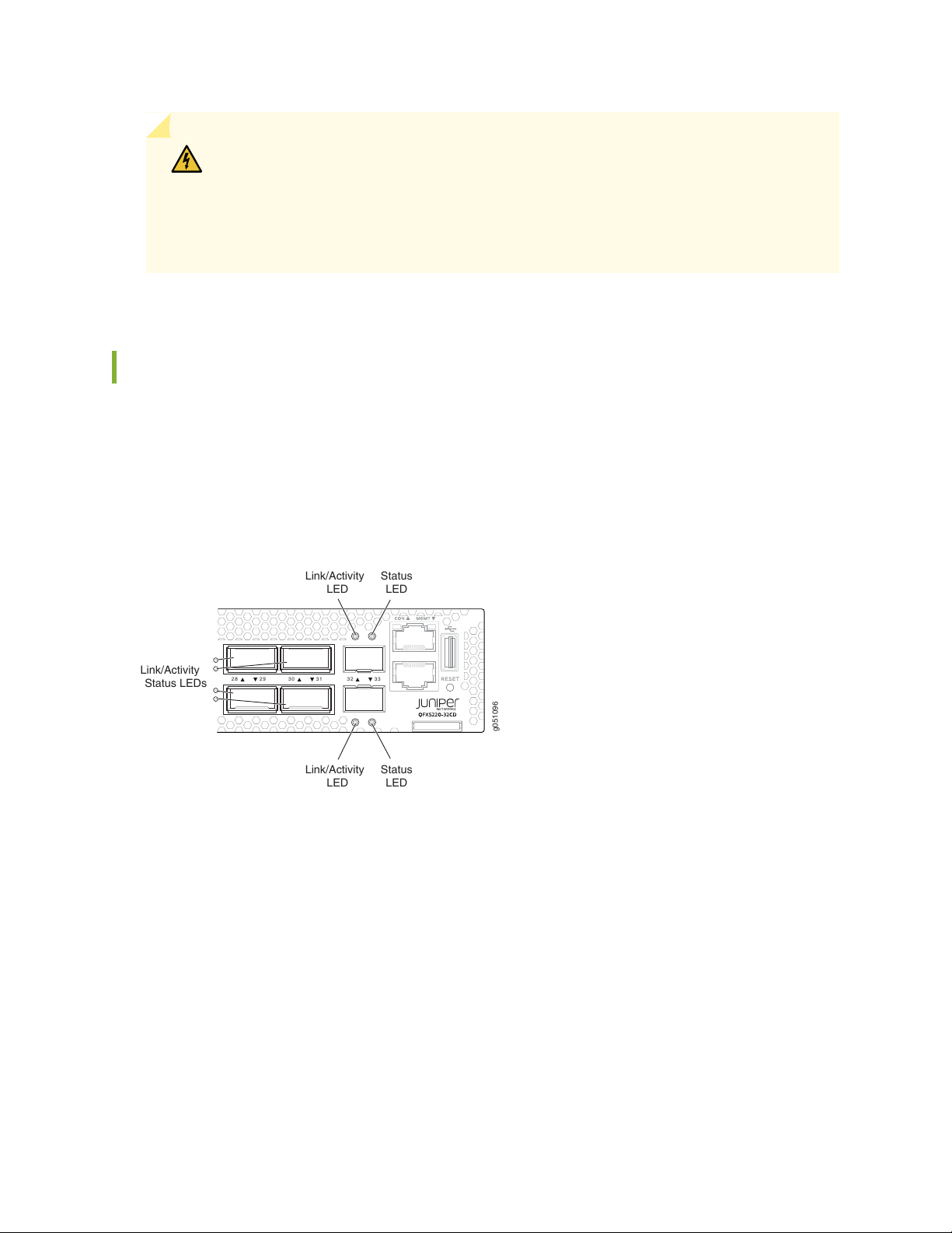
QFX5220-32CD Network LEDs
The high-speed QSFP-DD network ports use a single bi-colored LED to indicate link status, activity on the
link, or a fault condition. The 10-Gbps SFP+ ports have separate bi-colored LEDs; the left LED indicates
link and activity and the right LED indicates fault conditions. See Figure 5 on page 27.
27
Figure 5: Link/Activity LEDs on QFX5220-32CD
Table 6 on page 28 describes the various states of the network port LED for the high-speed ports.
Table 7 on page 28 describes how to interpret the link and activity LED and the status LEDs for the SFP+
ports.
Page 28

Table 6: QSFP-DD Network Port LEDs on a QFX5220-32CD
DescriptionChannelizedStateColor
28
NoOffUnlit
NoOn steadilyGreen
Yes
NoFlashing
Yes
Off is the default mode. The LED can be unlit even when
power is present and a transceiver is present in the port.
The port is administratively disabled.
•
The link is down.
•
A fault is detected on the link.
•
The port is administratively disabled.Yes
A 400-Gbps or 100-Gbps link is established, but there is
no activity.
All channels or subports have link established but there
is no activity.
A 400-Gbps or 100-Gbps link is established, and there is
link activity.
All channels or subports have links established and there
is link activity.
EitherAll LEDs
Blipping (slow
flashing)
YesFlashing
Table 7: SFP+ Network Port LEDs on QFX5220-32CD
flashing)
Indicates that the beacon feature is activated (service
request).
One or more interface or connection errors has occurred.EitherBlinkingAmber
At least one channel or subport has a link, but not all
channels or subports have links established.
DescriptionStateColorLED
Link down—The port does not have a connection.Link downOffLink/Activity
Link up—Theport has a connection, but there is noactivity.On steadilyGreen
Active link—Theport has a connection andthere is activity.Flashing
Beacon–The port has a service request.Blipping (slow
Page 29

Table 7: SFP+ Network Port LEDs on QFX5220-32CD (continued)
DescriptionStateColorLED
The port is configured for 10 Gbps.On steadilyGreenStatus
Fault–The port has an interface error.BlinkingAmber
RELATED DOCUMENTATION
Channelizing Interfaces on QFX3500, QFX3600, QFX5100, QFX10002, QFX10008, QFX10016, and
EX4600 Switches
QFX5220 Network Cable and Transceiver Planning | 92
Maintaining Transceivers and Fiber Optic Cables on a QFX5220 | 161
29
QFX5220-128C Port Panel
IN THIS SECTION
Overview | 29
Network Ports | 30
Port Configurations | 31
100-Gbps Port Configuration | 44
40-Gbps Port Configuration | 45
4 x 25 Gbps Port Channelization | 45
Delete 4 x 25 Gbps or 4 x 10 Gbps Port Channelization | 46
QFX5220-128C Network LEDs | 46
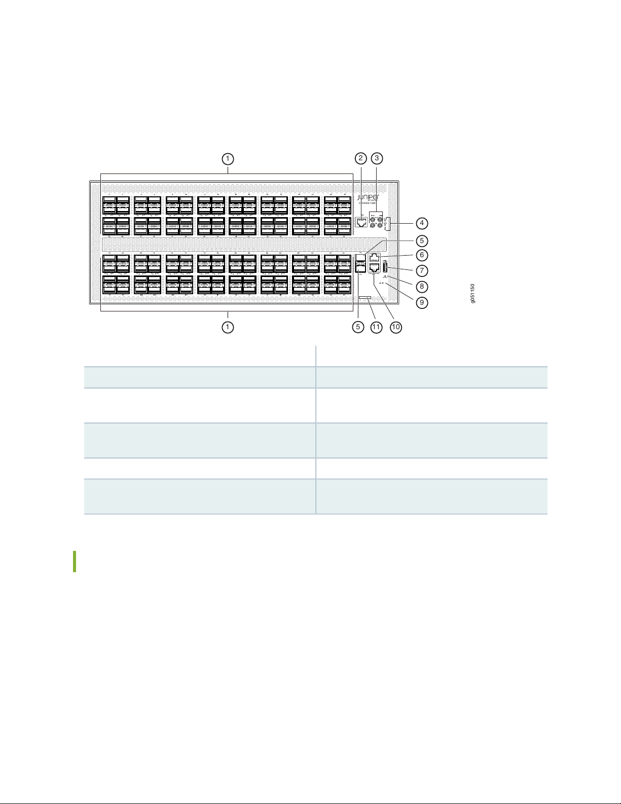
Overview
The port panel of the QFX5220-128C consists of 128 high-density 100-Gigabit Ethernet quad small
form-factor pluggablesolution (QSFP28) ports and the management panel.The highly flexible ports support
100-Gbps or 40-Gbps port speeds. The QFX5220-128C supports channelizing the QSFP28 ports to 4
Page 30
independent 25-Gbps speed interfaces. The switch has two dedicated 10-Gigabit Ethernet ports; 32 of
g051150
CON MGMT
128
129
RESET
1 32 3 34 5 36 7 38 9 40 11 42 13 44 15 46 17 48 19 50 21 52 23 54 25 56 27 58 29 60 31 62
65 96 67 98 69 100 71 102 73 104 75 106 77 108 79 110 81 112 83 114 85 116 87 118 89 120 91 122 93 124 95 126
QFX5220-128C
1
4
5
5
7
6
8
9
1011
1
32
the 128 ports can be channelized to 4 x 25-Gbps. See Figure 6 on page 30.
Figure 6: QFX5220-128C Port Panel
30
7—1— USB 2.0 port128 QSFP28 ports
8—2— Reset buttonRJ-45 time-of-day message port
9—3— ESD pointPTP-capable connections:SMB In, SMBOut, 10 MHz
In, 10 MHz Out
Chassis status alarms
10—4— RJ-45 MGMT connection for the re0:mgmt-0
management interface
11—5— Chassis serial number pull-out tab2 SFP+ ports
6—RJ-45 console port (CON) to support RS-232 serial
ports. (The LEDs indicate status and link.)
Network Ports
The QFX5220-128C QSFP28 network ports (0 to 127) support:
100-Gbps QSFP28 transceivers
•
100-Gbps QSFP28 direct attach copper (DAC) cables
•
100-Gbps QSFP28to 25-Gbps SFP28 direct attach copperbreak out (DACBO)cables (100-Gbps breaks
•
out to 4 independent 25-Gbps ports)
100-Gbps active optic cables (AOC)
•
Page 31

40-Gbps QSFP+ transceivers
•
40-Gbps AOC
•
40 Gbps QSFP+ DAC cables
•
40 Gbps QSFP+ transceivers
•
40 Gbps QSFP+ to 10 Gbps SFP+ DACBO cables (40 Gbps breaks out to 10 Gbps ports)
•
NOTE: Ports qualified for channelization support 100-Gbps QSFP28 to 25-Gbps SFP28 direct
attach copper break out (DACBO) cables (100-Gbps breaks out to 4 independent 25-Gbps.
The 10-Gbps network ports 128 (et-0/0/128) and 129 (et-0/0/129) support SFP+ transceivers.
Port Configurations
31
The QFX5220-128C has 128 QSFP28 ports and 2 SFP+ ports. You can configure any of these ports in
these combinations:
Any of the QSFP28 ports can be configured as 100 Gbps.
•
For Junos OS Evolved releases up to 20.2R1, you can configure any even-numbered QSFP28 port 40
•
Gbps speed.The system configures the next (odd) port as unused.For Junos OS Evolved releases 20.2R1
and later, you can configure all 128 QSFP28 ports for 40 Gbps speed.
Every fourthport (0, 4, 8...124) can be configured as channelized4 x 25 Gbps. Howeverbefore configuring
•
a port as channelized, the next three ports must be configured as unused.
Any SFP+ port can be configured as 10 Gbps or 1 Gbps.
•
Table 8 on page 31 shows how each QSFP28 port can be configured. You can mix and match speeds as
long as you adhereto the port rules. For example, on the same device youcan configure port 0 as 40 Gbps,
ports 2 and 3 as 100 Gbps, and port port as 4 x 25 Gbps. In this example, port 1 and port 5-7 must be
configured as unused unless you are running Junos OS Evolved Release 20.2R1 or later..
Table 8: QFX5220-128C Valid 100-Gbps Configurations
Ports
Configurable as
100 GbpsPort
Ports Configurable as 40
Gbps
Ports Configurable as channelized 4 x 25
Gbps
✓✓✓0
Page 32

Table 8: QFX5220-128C Valid 100-Gbps Configurations (continued)
Ports
Configurable as
100 GbpsPort
Ports Configurable as 40
Gbps
Ports Configurable as channelized 4 x 25
Gbps
32
✓1
Junos OS Evolved releases
✓ for Junos OS Evolved
20.2R1 and later
✓3
Junos OS Evolved releases
✓ for Junos OS Evolved
20.2R1 and later
✓5
Junos OS Evolved releases
✓ for Junos OS Evolved
20.2R1 and later
Configure as unusedConfigure as unused for initial
Configure as unused✓✓2
Configure as unusedConfigure as unused for initial
✓✓✓4
Configure as unusedConfigure as unused for initial
Configure as unused✓✓6
✓7
Junos OS Evolved releases
✓ for Junos OS Evolved
20.2R1 and later
✓9
Junos OS Evolved releases
✓ for Junos OS Evolved
20.2R1 and later
Configure as unusedConfigure as unused for initial
✓✓✓8
Configure as unusedConfigure as unused for initial
Configure as unused✓✓10
Page 33

Table 8: QFX5220-128C Valid 100-Gbps Configurations (continued)
Ports
Configurable as
100 GbpsPort
Ports Configurable as 40
Gbps
Ports Configurable as channelized 4 x 25
Gbps
33
✓11
Junos OS Evolved releases
✓ for Junos OS Evolved
20.2R1 and later
✓13
Junos OS Evolved releases
✓ for Junos OS Evolved
20.2R1 and later
✓15
Junos OS Evolved releases
✓ for Junos OS Evolved
20.2R1 and later
Configure as unusedConfigure as unused for initial
✓✓✓12
Configure as unusedConfigure as unused for initial
Configure as unused✓✓14
Configure as unusedConfigure as unused for initial
✓✓✓16
✓17
Junos OS Evolved releases
✓ for Junos OS Evolved
20.2R1 and later
✓19
Junos OS Evolved releases
✓ for Junos OS Evolved
20.2R1 and later
Configure as unusedConfigure as unused for initial
Configure as unused✓✓18
Configure as unusedConfigure as unused for initial
✓✓✓20
Page 34

Table 8: QFX5220-128C Valid 100-Gbps Configurations (continued)
Ports
Configurable as
100 GbpsPort
Ports Configurable as 40
Gbps
Ports Configurable as channelized 4 x 25
Gbps
34
✓21
Junos OS Evolved releases
✓ for Junos OS Evolved
20.2R1 and later
✓23
Junos OS Evolved releases
✓ for Junos OS Evolved
20.2R1 and later
✓25
Junos OS Evolved releases
✓ for Junos OS Evolved
20.2R1 and later
Configure as unusedConfigure as unused for initial
Configure as unused✓✓22
Configure as unusedConfigure as unused for initial
✓✓✓24
Configure as unusedConfigure as unused for initial
Configure as unused✓✓26
✓27
Junos OS Evolved releases
✓ for Junos OS Evolved
20.2R1 and later
✓29
Junos OS Evolved releases
✓ for Junos OS Evolved
20.2R1 and later
Configure as unusedConfigure as unused for initial
✓✓✓28
Configure as unusedConfigure as unused for initial
Configure as unused✓✓30
Page 35

Table 8: QFX5220-128C Valid 100-Gbps Configurations (continued)
Ports
Configurable as
100 GbpsPort
Ports Configurable as 40
Gbps
Ports Configurable as channelized 4 x 25
Gbps
35
✓31
Junos OS Evolved releases
✓ for Junos OS Evolved
20.2R1 and later
✓33
Junos OS Evolved releases
✓ for Junos OS Evolved
20.2R1 and later
✓35
Junos OS Evolved releases
✓ for Junos OS Evolved
20.2R1 and later
Configure as unusedConfigure as unused for initial
✓✓✓32
Configure as unusedConfigure as unused for initial
Configure as unused✓✓34
Configure as unusedConfigure as unused for initial
✓✓✓36
✓37
Junos OS Evolved releases
✓ for Junos OS Evolved
20.2R1 and later
✓39
Junos OS Evolved releases
✓ for Junos OS Evolved
20.2R1 and later
Configure as unusedConfigure as unused for initial
Configure as unused✓✓38
Configure as unusedConfigure as unused for initial
✓✓✓40
Page 36

Table 8: QFX5220-128C Valid 100-Gbps Configurations (continued)
Ports
Configurable as
100 GbpsPort
Ports Configurable as 40
Gbps
Ports Configurable as channelized 4 x 25
Gbps
36
✓41
Junos OS Evolved releases
✓ for Junos OS Evolved
20.2R1 and later
✓43
Junos OS Evolved releases
✓ for Junos OS Evolved
20.2R1 and later
✓45
Junos OS Evolved releases
✓ for Junos OS Evolved
20.2R1 and later
Configure as unusedConfigure as unused for initial
Configure as unused✓✓42
Configure as unusedConfigure as unused for initial
✓✓✓44
Configure as unusedConfigure as unused for initial
Configure as unused✓✓46
✓47
Junos OS Evolved releases
✓ for Junos OS Evolved
20.2R1 and later
✓49
Junos OS Evolved releases
✓ for Junos OS Evolved
20.2R1 and later
Configure as unusedConfigure as unused for initial
✓✓✓48
Configure as unusedConfigure as unused for initial
Configure as unused✓✓50
Page 37

Table 8: QFX5220-128C Valid 100-Gbps Configurations (continued)
Ports
Configurable as
100 GbpsPort
Ports Configurable as 40
Gbps
Ports Configurable as channelized 4 x 25
Gbps
37
53
✓51
Junos OS Evolved releases
✓ for Junos OS Evolved
20.2R1 and later
Junos OS Evolved releases
✓ for Junos OS Evolved
20.2R1 and later
✓55
Junos OS Evolved releases
✓ for Junos OS Evolved
20.2R1 and later
Configure as unusedConfigure as unused for initial
✓✓✓52
Configure as unusedConfigure as unused for initial
Configure as unused✓✓54
Configure as unusedConfigure as unused for initial
✓✓✓56
✓57
Junos OS Evolved releases
✓ for Junos OS Evolved
20.2R1 and later
✓59
Junos OS Evolved releases
✓ for Junos OS Evolved
20.2R1 and later
Configure as unusedConfigure as unused for initial
Configure as unused✓✓58
Configure as unusedConfigure as unused for initial
✓✓✓60
Page 38

Table 8: QFX5220-128C Valid 100-Gbps Configurations (continued)
Ports
Configurable as
100 GbpsPort
Ports Configurable as 40
Gbps
Ports Configurable as channelized 4 x 25
Gbps
38
✓61
Junos OS Evolved releases
✓ for Junos OS Evolved
20.2R1 and later
✓63
Junos OS Evolved releases
✓ for Junos OS Evolved
20.2R1 and later
✓65
Junos OS Evolved releases
✓ for Junos OS Evolved
20.2R1 and later
Configure as unusedConfigure as unused for initial
Configure as unused✓✓62
Configure as unusedConfigure as unused for initial
✓✓✓64
Configure as unusedConfigure as unused for initial
Configure as unused✓✓66
✓67
Junos OS Evolved releases
✓ for Junos OS Evolved
20.2R1 and later
✓69
Junos OS Evolved releases
✓ for Junos OS Evolved
20.2R1 and later
Configure as unusedConfigure as unused for initial
✓✓✓68
Configure as unusedConfigure as unused for initial
Configure as unused✓✓70
Page 39

Table 8: QFX5220-128C Valid 100-Gbps Configurations (continued)
Ports
Configurable as
100 GbpsPort
Ports Configurable as 40
Gbps
Ports Configurable as channelized 4 x 25
Gbps
39
✓71
Junos OS Evolved releases
✓ for Junos OS Evolved
20.2R1 and later
✓73
Junos OS Evolved releases
✓ for Junos OS Evolved
20.2R1 and later
✓75
Junos OS Evolved releases
✓ for Junos OS Evolved
20.2R1 and later
Configure as unusedConfigure as unused for initial
✓✓✓72
Configure as unusedConfigure as unused for initial
Configure as unused✓✓74
Configure as unusedConfigure as unused for initial
✓✓✓76
✓77
Junos OS Evolved releases
✓ for Junos OS Evolved
20.2R1 and later
✓79
Junos OS Evolved releases
✓ for Junos OS Evolved
20.2R1 and later
Configure as unusedConfigure as unused for initial
Configure as unused✓✓78
Configure as unusedConfigure as unused for initial
✓✓✓80
Page 40

Table 8: QFX5220-128C Valid 100-Gbps Configurations (continued)
Ports
Configurable as
100 GbpsPort
Ports Configurable as 40
Gbps
Ports Configurable as channelized 4 x 25
Gbps
40
✓81
Junos OS Evolved releases
✓ for Junos OS Evolved
20.2R1 and later
✓83
Junos OS Evolved releases
✓ for Junos OS Evolved
20.2R1 and later
✓85
Junos OS Evolved releases
✓ for Junos OS Evolved
20.2R1 and later
Configure as unusedConfigure as unused for initial
Configure as unused✓✓82
Configure as unusedConfigure as unused for initial
✓✓✓84
Configure as unusedConfigure as unused for initial
Configure as unused✓✓86
✓87
Junos OS Evolved releases
✓ for Junos OS Evolved
20.2R1 and later
✓89
Junos OS Evolved releases
✓ for Junos OS Evolved
20.2R1 and later
Configure as unusedConfigure as unused for initial
✓✓✓88
Configure as unusedConfigure as unused for initial
Configure as unused✓✓90
Page 41

Table 8: QFX5220-128C Valid 100-Gbps Configurations (continued)
Ports
Configurable as
100 GbpsPort
Ports Configurable as 40
Gbps
Ports Configurable as channelized 4 x 25
Gbps
41
✓91
Junos OS Evolved releases
✓ for Junos OS Evolved
20.2R1 and later
✓93
Junos OS Evolved releases
✓ for Junos OS Evolved
20.2R1 and later
✓95
Junos OS Evolved releases
✓ for Junos OS Evolved
20.2R1 and later
Configure as unusedConfigure as unused for initial
✓✓✓92
Configure as unusedConfigure as unused for initial
Configure as unused✓✓94
Configure as unusedConfigure as unused for initial
✓✓✓96
✓97
Junos OS Evolved releases
✓ for Junos OS Evolved
20.2R1 and later
✓99
Junos OS Evolved releases
✓ for Junos OS Evolved
20.2R1 and later
Configure as unusedConfigure as unused for initial
Configure as unused✓✓98
Configure as unusedConfigure as unused for initial
✓✓✓100
Page 42

Table 8: QFX5220-128C Valid 100-Gbps Configurations (continued)
Ports
Configurable as
100 GbpsPort
Ports Configurable as 40
Gbps
Ports Configurable as channelized 4 x 25
Gbps
42
✓101
Junos OS Evolved releases
✓ for Junos OS Evolved
20.2R1 and later
✓103
Junos OS Evolved releases
✓ for Junos OS Evolved
20.2R1 and later
✓105
Junos OS Evolved releases
✓ for Junos OS Evolved
20.2R1 and later
Configure as unusedConfigure as unused for initial
Configure as unused✓✓102
Configure as unusedConfigure as unused for initial
✓✓✓104
Configure as unusedConfigure as unused for initial
Configure as unused✓✓106
✓107
Junos OS Evolved releases
✓ for Junos OS Evolved
20.2R1 and later
✓109
Junos OS Evolved releases
✓ for Junos OS Evolved
20.2R1 and later
Configure as unusedConfigure as unused for initial
✓✓✓108
Configure as unusedConfigure as unused for initial
Configure as unused✓✓110
Page 43

Table 8: QFX5220-128C Valid 100-Gbps Configurations (continued)
Ports
Configurable as
100 GbpsPort
Ports Configurable as 40
Gbps
Ports Configurable as channelized 4 x 25
Gbps
43
✓111
Junos OS Evolved releases
✓ for Junos OS Evolved
20.2R1 and later
✓113
Junos OS Evolved releases
✓ for Junos OS Evolved
20.2R1 and later
✓115
Junos OS Evolved releases
✓ for Junos OS Evolved
20.2R1 and later
Configure as unusedConfigure as unused for initial
✓✓✓112
Configure as unusedConfigure as unused for initial
Configure as unused✓✓114
Configure as unusedConfigure as unused for initial
✓✓✓116
✓117
Junos OS Evolved releases
✓ for Junos OS Evolved
20.2R1 and later
✓119
Junos OS Evolved releases
✓ for Junos OS Evolved
20.2R1 and later
Configure as unusedConfigure as unused for initial
Configure as unused✓✓118
Configure as unusedConfigure as unused for initial
✓✓✓120
Page 44

Table 8: QFX5220-128C Valid 100-Gbps Configurations (continued)
Ports
Configurable as
100 GbpsPort
Ports Configurable as 40
Gbps
Ports Configurable as channelized 4 x 25
Gbps
44
✓121
Junos OS Evolved releases
✓ for Junos OS Evolved
20.2R1 and later
✓123
Junos OS Evolved releases
✓ for Junos OS Evolved
20.2R1 and later
✓125
Junos OS Evolved releases
✓ for Junos OS Evolved
20.2R1 and later
Configure as unusedConfigure as unused for initial
Configure as unused✓✓122
Configure as unusedConfigure as unused for initial
✓✓✓124
Configure as unusedConfigure as unused for initial
Configure as unused✓✓126
✓127
Junos OS Evolved releases
✓ for Junos OS Evolved
20.2R1 and later
Configure as unusedConfigure as unused for initial
100-Gbps Port Configuration
All QSFP28 ports support either 40 Gbps or 100 Gbps. Use the set chassis fpc 0 pic 0 port port-num speed
100g command to configure ports 0 to 127 for 100-Gbps speed and commit the configuration.
Page 45

40-Gbps Port Configuration
Before configuring a port for 40 Gbps, determine its associated used port (see Table 8 on page 31). In the
following example,you would need to configure the neighboring port firstbefore configuring port et-0/0/0.
If you are running a newer software release, you can skip to Step 2.
1. Block theport following the desired 40-Gbps port asunused and commit the configuration. For example,
because you are configuringet-0/0/0 as 40 Gbps, you must firstconfigure the following port (et-0/0/1)
as unused and commit that configuration.
# set chassis fpc 0 pic 0 port 1 unused
# commit
2. Configure the speed on the desired port (et-0/0/0) as 40 Gbps and commit the configuration.
# set chassis fpc 0 pic 0 port 0 speed 40g
# commit
45
4 x 25 Gbps Port Channelization
Before configuring a port for channelization, determine its associated used ports (see Table 8 on page 31).
In the following example, you’ll configure port et-0/0/4 to operate as a 4 x 25 Gbps channelized port.
1. Block the three ports following the desired channelized port as unused, and commit the configuration.
For example,because you are configuring et-0/0/4 as 4 x 25Gbps, you must first configurethe following
ports (et-0/0/5, et-0/0/6, and et-0/0/7) as unused and commit the configuration.
# set chassis fpc 0 pic 0 port 5 unused
# set chassis fpc 0 pic 0 port 6 unused
# set chassis fpc 0 pic 0 port 7 unused
# commit
Software removes these ports and updates the configuration.
2. Configure the speed on the desired port (et-0/0/4) as 25 Gbps, the number -of sub-ports as 4, and
commit the configuration:
# set chassis fpc 0 pic 0 port 4 speed 25g number-of-sub-ports 4
# commit
Page 46

Delete 4 x 25 Gbps or 4 x 10 Gbps Port Channelization
To remove the channelization configuration from a set of QFX5220-128C ports, delete the configuration
from the channelized port and commit the configuration. For example:
# delete chassis fpc 0 pic 0 port port-number number-of-sub-ports 4
# delete chassis fpc 0 pic 0 port port-number speed port-speed
# commit
WARNING: An incorrectly configured port can cause unexpected port and switch
behavior. The system software doesnot check whether the port speed or the attached
optic are supported at the time of the commit. Use the show chassis alarms and the
show chassis pic fpc-slot 0 pic-slot 0 to locate incorrectly configured ports. See
“Configuration Changes Leading to Unexpected QFX5220 Behavior” on page 179.
46
QFX5220-128C Network LEDs
The QSFP28 network ports use a single bi-colored LED for each port or channel to indicate link status,
activity on the link, or a fault condition. When the port is channelized, there is an LED for each channel;
when the port is not channelized, the left-most LED indicates the port link status.
The 10-Gbps SFP+ ports have separate bi-colored LEDs; the left LED indicates link and activity and the
right LED indicates a fault condition. See Figure 7 on page 47.
Page 47

Figure 7: Link/Activity and Status LEDs on QFX5220-128C
g051178
1 32 3 34
1
1
2
2—1— SFP+ :LEDs that indicate link/activity and statusQSFP28 LEDs that indicate link/activity,status, and
channelization
47
Table 9 on page 47 describe the various states of the LEDs for the QSFP28 ports and Table 10 on page 48
describe the LED states for the SFP+ ports.
Table 9: Network Port LEDs on QSFP28 Ports on a QFX5220-128C Switch
ChannelizedNon-ChannelizedStateColor
OffUnlit
The port is administratively disabled, there
is no power, the link is down, no module is
present, or the interface is disabled.
On steadilyGreen
activity.
There is an interface error.Blinking
A module is not present, all sub-channels
are disabled, or there is no link.
All sub-channels are up.A link is established, but there is no link
The interface is up with activity.A link is established, and thereis link activity.Flashing
The beacon is enabled on the port.The beacon is enabled on the port.Blipping
At least one, but not all sub-channels are up.NAOn steadilyAmber
There is an error on one or more
sub-channels.
NAFlashing
At least one, but not all sub-channels are up
with activity.
Page 48

Table 10: Network Port LEDs on SFP+ Ports on a QFX5220-128C Switch
DescriptionStateColorLED
48
OffUnlitLink/Activity
On steadilyGreen
BlinkingGreen
The port is administratively disabled, there is no power, the link
is down, or there is a fault.
A link is established, but there is no link activity.On steadilyGreen
A link is established, and there is link activity.Blinking
The beacon is enabled on the port.BlinkingAmber
The link is down or there is a fault.OffUnlitStatus
A 10-Gigabit Ethernet transceiveris installed in the portand link
is established.
A 1-Gigabit Ethernet transceiver is installed in the port and the
link is established.
The beacon function is enabled on the port.Slow blippingAmber
QFX5220 Management Panel
IN THIS SECTION
QFX5220-128C Management Panel Overview | 49
QFX5220-32CD Management Panel Overview | 49
QFX5220-32CD Management Panel LEDs | 50
The management panel allows you to have a management channel into the switch that is separate from
production traffic.
Page 49

QFX5220-128C Management Panel Overview
g051150
CON MGMT
128
129
RESET
1 32 3 34 5 36 7 38 9 40 11 42 13 44 15 46 17 48 19 50 21 52 23 54 25 56 27 58 29 60 31 62
65 96 67 98 69 100 71 102 73 104 75 106 77 108 79 110 81 112 83 114 85 116 87 118 89 120 91 122 93 124 95 126
QFX5220-128C
1
4
5
5
7
6
8
9
1011
1
32
The management panel of the QFX5220-128C is located to the right of the network ports.
Figure 8 on page 49 shows the connections and components of the management panel and the network
ports.
Figure 8: QFX5220-128C Port and Management Panels
49
RJ-45 grandmaster time-of-day connection
Out , PPS In, 10 MHz Out, 10 MHz In
Chassis alarms LEDs
6—RJ-45 console (CON) port
QFX5220-32CD Management Panel Overview
The management panel of the QFX5220-32CD is divided in two sections, with the port panel in between
these sections. Figure 9 on page 50 shows the connections and components of the management panel
and the network ports.
7—1— USB port for image updatesNetwork ports or port panel, 128 ports of QSFP28
8—2— Reset button (do not use unless under the direction
of JTAC)
9—3— ESD connection pointPTP capable connections: pulses per second (PPS)
10—4— RJ-45 (1000BASE-T) management Ethernet (MGMT
port for the re0:mgmt-0 management interface)
11—5— Slide-out tab for chassis serial number1-Gbps or 10-Gbps ports, 2 ports of SFP+
Page 50

Figure 9: QFX5220-32CD Port and Management Panels
g051050
TOD
ALM
SYS
ID
10M
IN
OUT
PPS
10 3 54 76 8 110 1312 1514 1716 1918 2120 2322 252 4 272 6 2928 313 0 333 22 9 1
RESET
MGMTCON
1 2
3
89
1011
54
7
6
50
RJ-45 grandmaster time-of-day connection
7—1— Reset button (do not use unless under the direction
of JTAC)
8—2— Slide out tab for chassis serial numberChassis alarms LEDs
9—3— Network ports, 10-Gigabit Ethernet portsNetwork ports or port panel, 32 ports of QSFP-DD
10—4— PTP and external clock connectionsRJ-45 (1000BASE-T) management Ethernet (MGMT
port for the re0:mgmt-0 management interface)
11—5— ESD connection pointRJ-45 console (CON) port
6—USB port for image updates
QFX5220-32CD Management Panel LEDs
IN THIS SECTION
QFX5220 Chassis Status LEDs | 51
RJ-45 Management Port LEDs | 54
You can find LEDs on these management panel ports:
Chassis status LEDs
•
RJ-45 Console and Management Port LEDs
•
The following sections explain how to interpret these LEDs.
Page 51

QFX5220 Chassis Status LEDs
g051177
29 60 31 62
QFX5220-128C
1
g051094
1
Both models of the QFX5220 have a series of three LEDs that indicate system status. On the
QFX5220-128C, you can find these LEDs to the right of the network ports (see Figure 10 on page 51).
On theQFX5220-32CD, you can find these LEDs tothe left of the networkports (see Figure11 on page 51).
Figure 10: QFX5220-128C Chassis Status LEDs
51
1—ALM—Chassis alarm or fault
SYS—System status
ID—Beacon
Figure 11: QFX5220-32CD Chassis Status LEDs
1—ALM—Chassis alarm or fault
SYS—System status
ID—Beacon
Table 11 on page 53 describes the chassis status LEDs on a QFX5220, the colors and states, and the status
they indicate. You canview the colors of thethree LEDsremotely through the CLI byissuing the operational
mode command show chassis lcd.
user@host> show chassis led
Page 52

----------------------------------LEDs status:
Alarm LED : Red
Beacon LED: Off
System LED: Green
Interface STATUS LED LINK/ACTIVITY LED
--------------------------------------------------------et-0/0/0 N/A Off
et-0/0/1 N/A Off
et-0/0/2 N/A Off
et-0/0/3 N/A Off
et-0/0/4 N/A Off
et-0/0/5 N/A Off
et-0/0/6 N/A Off
et-0/0/7 N/A Off
et-0/0/8 N/A Off
et-0/0/9 N/A Off
et-0/0/10 N/A Green
et-0/0/11 N/A Off
et-0/0/12 N/A Off
et-0/0/13 N/A Off
et-0/0/14 N/A Off
et-0/0/15 N/A Off
et-0/0/16 N/A Green
et-0/0/17 N/A Off
et-0/0/18 N/A Green
et-0/0/19 N/A Off
et-0/0/20 N/A Off
et-0/0/21 N/A Off
et-0/0/22 N/A Off
et-0/0/23 N/A Off
et-0/0/24 N/A Off
et-0/0/25 N/A Off
et-0/0/26 N/A Green
et-0/0/27 N/A Green
et-0/0/28 N/A Green
et-0/0/29 N/A Off
et-0/0/30 N/A Green
et-0/0/31 N/A Off
et-0/0/32 N/A Off
et-0/0/33 N/A Off
52
Page 53

Table 11: Chassis Status LEDs on a QFX5220-Devices
53
DescriptionStateColorName
OffUnlitALM–Alarm
On steadilyRed
On steadilyAmber
The switch is halted or there is no
alarm.
A major hardware fault has occurred,
such as a temperature alarm, power
failure, or media failure. The device has
halted. Poweroff the device bysetting
the ACpower source outletto the OFF
(O) position, or unplugging the AC
power cords. Correct any voltage or
site temperature issues, and allow the
switch to cool down. Power on the
QFX5220. Monitor the power supply
and fan LEDs tohelp determine where
the error is occurring.
A minor system level alarm has
occurred, such as a software error or
a missing rescue configuration. Power
off thedevice by settingthe AC power
source outlet to the OFF (O) position,
or unplugging the AC power cords.
Power on the QFX5220 and monitor
the status LEDs to ensure that Junos
OS Evolved boots properly.
The device is powered off or halted.OffUnlitSYS–System
On steadilyGreen
OffUnlitID–Identification
BlinkingBlue
Junos OS Evolved is loaded on the
device.
The beacon feature is not enabled on
the switch. Enable this feature by using
the request chassis beacon fpc 0 on
operational CLI command.
The beacon feature is enabled on the
switch. Disable this feature by using
the request chassis beacon fpc 0 off
operational CLI command.
Page 54

Table 11: Chassis Status LEDs on a QFX5220-Devices (continued)
g051078
RESE T
MGM T
CON
1 2
DescriptionStateColorName
TIP: To find the status of the beacon, use the show chassis beacon operational CLI command.
user@host> show chassis beacon fpc 0
FPC 0 OFF
RJ-45 Management Port LEDs
The management port on a QFX5220-32CD has two LEDs that indicate link status and link activity. The
management port is labeled MGMT for 10/100/1000BASE-T connections.
54
2—1— Status LEDLink and activity LED
Table 12 on page 54 describes the management port LEDs.
Table 12: Management Port LEDs on a QFX5220-32CD
DescriptionStateColorLED
OffUnlitLink/Activity
No link is established, there is a fault, or the link is
down.
A link is established, but there is no link activity.On steadilyGreen
A link is established, and there is link activity.Blinking or flickering
Either the port speed is 10 MB or the link is down.OffUnlitStatus
The port speed is 1-Gbps.On steadilyGreen
The port speed is 100 MB.On steadilyAmber
Page 55

RELATED DOCUMENTATION
show system alarms
request chassis beacon
QFX5220 Cooling System
IN THIS SECTION
QFX5220-128C Cooling System Description | 55
QFX5220-128C Fan Module LED | 57
QFX5220-32CD Cooling System Description | 57
QFX5220-32CD Fan Module LED | 61
55
Fan Module Status | 62
QFX5220-128C Cooling System Description
IN THIS SECTION
Fan Modules | 55
The cooling system in an QFX5220-128C consists of six 80-W fan modules and two counter-rotating fans
housed in each of the four power supplies.
Fan Modules
The fanmodules in aQFX5220-128C are hot-removable and hot-insertableFRUs designed for port-to-FRU
airflow. The fan module are numbered across from top left 0 to the bottom right corner 5. Each fan is 2
U high. See Figure 12 on page 56.
Page 56

Figure 12: Fan module for QFX5220-128C
g051168
g051192
Ports FRUs
The QFX5220-128C brings air into the vents in the port panel and exhausts warmed air through the
field-replaceable units (FRU) panel.This typeof airflow is know as airflow out or port-to-FRU airflow. Airflow
out fans are distinguished by AIR OUT marking on the orange (Juniper gold) handles. In data center
deployments, position the switch in such a manner that the AIR OUT labels on the switch components
are next to the hot aisle.
56
You remove and replace a fan module from the FRU end of the chassis. The switch continues to operate
for a limited period of time (30 seconds) during the replacement of the fan module without thermal
shutdown. Figure 13 on page 56 shows the airflow through the chassis.
Figure 13: Air Out Airflow Through the QFX5220-128C Chassis
Page 57

NOTE: The fans provide a (5x2+1)+1 redundancy. However, foroptimal operation ofthe device,
0
2
1
3
g051180
1
1
install all of the fans.
QFX5220-128C Fan Module LED
Each fan module has an associated LED to indicate status. On the QFX5220-128C, the fan LED is located
to the right of each fan below a fan icon. See Figure 14 on page 57 for the location of these LEDs.
Figure 14: Fan Module LEDs on a QFX5220-128C
57
1—Fan module LEDs
The LED behavior is common for both QFX5220-32CD and QFX5220-128C. For information on how to
interpret the LEDs, see Table 14 on page 62.
QFX5220-32CD Cooling System Description
IN THIS SECTION
Fan Modules | 58
Do Not Install Components with Different Airflow or Wattage in the Switch | 60
Page 58

The coolingsystem in an QFX5220-32CD consists of six fan modulesand a single fan in each power supply.
g051067
The switch can ordered in one of two airflow directions:
Airflow In–Air comes into the switch through the vents in the field-replaceable units (FRUs)
•
Airflow Out–Air comes into the switch through the vents in the port panel.
•
CAUTION: Airflow In and Airflow Out fans and power supplies cannot be mixed in
the same chassis.
Fan Modules
The fanmodules in QFX5220 devices are hot-insertableand hot-removable field-replaceableunits (FRUs).
These fan modules are designed for one of the two available airflow directions (Airflow In or Airflow Out).
The fan modules are also color-coded for the airflow direction as well. The fan modules are installed in
the fan module slots on the FRU panel.
58
The QFX5220-32CD fan modules have six fan modules numbered 0 through 5 when counting from left
to right.
Figure 15 on page 58 shows a fan module.
Figure 15: QFX5220-32CD Fan Module
You remove and replace a fan module from the FRU end of the chassis. The switch can work with only
five fans. However, we recommend running with all six fans for redundancy and optimal operation of the
switch. If a fan fails, or you want to run the switch without redundancy, leave the sixth fan in place to
maintain proper airflow. When you replace a fan, the switch continues to operate for a limited period of
time (3 minutes) without thermal alarms or shutdown.
The fan modules are available in two product variants that have different airflow directions—FRU-to-port
airflow and port-to-FRU airflow Table 13 on page 59 lists the available fan module product variants and
the direction of airflow in them:
Page 59

Table 13: Fan Modules in QFX5220 Switches
59
Label on
the Fan
ModuleAirflow DiagramFan Module
AIR INFigure 16on page60QFX5220-32CD-FANAI
AIR OUTFigure 17 onpage 60QFX5220-32CD-FANAO
Color of
Fan
Module
Juniper
azure blue
Juniper
gold
Direction ofAirflow
in the Fan Module
FRU-to-port, that is,
air comes in from the
end ofthe switch with
the fans; air exhausts
from the switch end
with ports(also known
as back-to-front
airflow).
Port-to-FRU, that is,
air comes in through
vents on the end with
ports; airexhausts out
the end with the fans
(also known as
front-to-back airflow).
Power
Supplies
You must
install only
power supplies
that have AIR
IN labels in
switches in
which the fan
modules have
AIR IN labels.
You must
install only
power supplies
that have AIR
OUT labels in
switches in
which the fan
modules have
AIR OUT
labels.
In data center deployments, position the switch in such a manner that the AIR IN labels on switch
components are next to the cold aisle, and AIR OUT labels on switch components are next to the hot
aisle.
Page 60

Figure 16: Air In Airflow Through QFX5220-32CD
g051085
Ports
FRUs
g051086
Ports FRUs
60
Figure 17: Air Out Airflow Through QFX5220-32CD
Do Not Install Components with Different Airflow or Wattage in the Switch
Do not mix airflow direction on fans or power supplies. You can use the color-coding on fan and power
supply handles to ensure the airflow direction matches. The handles on Airflow In fans and power supplies
are azure blue, compared to the Airflow Out fans and power supplies, which are Juniper gold.
Mixing components with different airflows in the same chassis hampers the performance of the cooling
system of the switch and leads to overheating of the chassis.
Page 61

CAUTION: The system raises an alarm if a fan module fails or if the ambient
temperature inside the chassis rises above the acceptable range. If the temperature
inside the chassis rises above the threshold temperature, the system shuts down
automatically. Thesystem takes 240 seconds toshut down after the red alarm threshold
is reached.
Do not mix fan modules with different wattage. Only use the replacement fan modules that are designed
for usewith your productnumber. See Table13 on page59 for thecorrect part numberfor your QFX5220
device.
CAUTION: Do not mix AC and DC power supplies in the same QFX5220 chassis.
However, if you need to converta QFX5220 device to have a different airflow, you can change the airflow
pattern. To convert an AIR IN product variant to an AIR OUT product variant or an AIR OUT product
variant to a AIR IN product variant, you must power off and replace all of the fans and power supplies at
one time to use the new direction. The system raises an alarm when the system is converted, which is
normal.
61
NOTE: If you change the switch to have a different airflow, be sure to update your JTAC install
base to reflect the new configuration to ensure service warranties and contracts remain˙.
QFX5220-32CD Fan Module LED
On the QFX5220-32CD switches, the fan module LEDs are located on the chassis next to the fan module
slot. Figure 18 on page 62 shows the location of the fan module LEDs next to the fan module on a
QFX5220-32CD switch.
Page 62

Figure 18: Fan Module LEDs on a QFX5220-32CD
g051076
1
1—Fan module LED
Table 14 on page 62 describes the function of the fan tray LED.
Table 14: Fan Tray LED Behavior in a QFX5220
62
DescriptionStateColorName
On steadilyGreenFan
BlinkingAmber
The fanmodule is operatingnormally. The system
has verified that themodule is engaged, that the
airflow is in the correct direction, and that the
fan is operating correctly.
An error has been detected in the fan module.
Replace the fan module as soon as possible.
Either the fan has failed or it is seatedincorrectly.
To maintain proper airflow through the chassis,
leave the fan module installed in the chassis until
you are ready to replace it.
Under normal operating conditions, the fan modules operate at a moderate speed. Temperature sensors
in the chassis monitor the temperature within the chassis.
The systemraises an alarm if a fan module fails or ifthe ambient temperature inside the chassis rises above
the acceptable range. If the temperature inside the chassis rises above the threshold temperature, the
system shuts down automatically.
Fan Module Status
You can check the status of fan modules through the show chassis temperature-thresholds, show system
alarm, or show chassis environment commands, or by looking at the LEDs next to each fan module. For
example:
user@device> show chassis environment
Page 63

Class Item Status Measurement
Temp PSM 1 Ok 25 degrees C / 77 degrees F
PSM 3 Ok 25 degrees C / 77 degrees F
FPC 0 Sensor MainTopBack Ok 32 degrees C / 89 degrees F
FPC 0 Sensor MainTopBackRight Ok 32 degrees C / 89 degrees F
FPC 0 Sensor MezzPhysLeftSide Ok 26 degrees C / 78 degrees F
FPC 0 Sensor MezzPhysRightSide Ok 26 degrees C / 78 degrees F
FPC 0 Sensor NearTH3 Ok 30 degrees C / 86 degrees F
63
FPC 0 Sensor MainPhysLeftSide Ok 26 degrees C / 78 degrees F
FPC 0 Sensor MainPhysRightSide Ok 26 degrees C / 78 degrees F
FPC 0 Sensor TopLeftCpuBoard Ok 27 degrees C / 80 degrees F
FPC 0 Sensor TopBackRightCpuBoard Ok 27 degrees C / 80 degrees F
FPC 0 Sensor BottomMiddleCpuBoard Ok 31 degrees C / 87 degrees F
FPC 0 Sensor TH3 Max Reading Ok 44 degrees C / 111 degrees F
Routing Engine 0 CPU Temperature Ok 41 degrees C / 105 degrees F
Fan Fan Tray 0 Fan 1 Ok 4395 RPM
Fan Tray 0 Fan 2 Ok 4688 RPM
Page 64

Fan Tray 1 Fan 1 Ok 4688 RPM
Fan Tray 1 Fan 2 Ok 4688 RPM
Fan Tray 2 Fan 1 Ok 4688 RPM
Fan Tray 2 Fan 2 Ok 4981 RPM
Fan Tray 3 Fan 1 Ok 4688 RPM
Fan Tray 3 Fan 2 Ok 4981 RPM
Fan Tray 4 Fan 1 Ok 4395 RPM
Fan Tray 4 Fan 2 Ok 4981 RPM
Fan Tray 5 Fan 1 Ok 4395 RPM
Fan Tray 5 Fan 2 Ok 4981 RPM
64
The QFX5220 has a status LED (labeled ST) for each fan module. It indicates the status of all the fan
modules.
RELATED DOCUMENTATION
Maintaining QFX5220 Cooling System | 151
QFX5220 Power System
IN THIS SECTION
QFX5220 AC Power Supply Modules Description | 66
QFX5220 AC Power Specifications | 68
AC Power Cord with Type C13 Coupler Specifications | 69
AC Power Cord with Type C15 Coupler Specifications | 71
Page 65

QFX5220 AC Power Supply LEDs | 73
QFX5220 DC Power Supply Description | 74
QFX5220 DC Power Specifications | 76
QFX5220-128C DC Power Cable Specification | 77
QFX5220-128C DC Power Supply LED | 78
QFX5220-32CD-D DC Power Supply LED | 79
The power supplies in QFX5220 models are hot-removable and hot-insertable field-replaceable units
(FRUs). You can installreplacement power supplies without poweringoff the device or disrupting switching
function. The power supplies are installed at the factory and shipped with the chassis. All power supplies
for QFX5220 are 1600 W; however, the power supplies for the QFX5220-32CD and the QFX5220-128C
are not interchangeable.
65
CAUTION: Only use the power supply for your model number and airflow. Do not
mix power supplies with different airflow or different wattage. The system raises an
alarm when a power supply having a different airflow or wattage is inserted into the
chassis.
The power supplies for the QFX5220 are located on the FRU panel. See Figure 19 on page 66 and
Figure 20 on page 66.
Page 66

Figure 19: QFX5220-128C FRU Panel
0
2
0 1 2
3 4 5
1
3
g051151
2
21
3
1
1
1
g051051
115-240V ; 50-60Hz; 12.7-9 .4AACINPUT:
+12V 90A,+5V SB 3A
DCINPUT:
1200WMAXFOR 115~127V INPUT
+12V 133A,+5VSB 3A
1600WMAXFOR 200~2 40V INPUT
0 1
1 2 1
2—Fans
66
3—1— Chassis protective earthing terminalPower supplies
Figure 20: QFX5220-32CD FRU Panel
2—1— FansPower supplies
QFX5220 AC Power Supply Modules Description
The QFX5220-32CD ships with two power supplies; the QFX5220-128C ships with four power supplies.
While each model can operate with the minimum number of power supplies (one for QFX5220-32CD,
two for QFX5220-128C), maximum power supplies are required to have redundancy. See
Figure 21 on page 67 and Figure 22 on page 67 for examples of these power supply modules.
Page 67

Figure 21: 1600-W AC Power Supply for QFX5220-32CD
g051057
Figure 22: 1600-W AC Power Supply for QFX5220-128C
67
3—1— Ejection leverPower connector
4—2— HandlePower LED
An AC power supply for the QFX5220 is 1600 W. However, the power supplies for the QFX5220-32CD
and the QFX5220-128C are not interchangeable. Be sure to use the correct power supply for your chassis
product variant (see Table 15 on page 67).
The power supply provides FRU-to-port or port-to-FRU airflow depending on the model and variant you
purchase. The power supplies have color-coded indicators to indicate the airflow direction.
Table 15: DC Power Supply Summary
Color IndicatorAirflow DirectionProduct NumberModel
Juniper azure blue handleAirflow In (FRU-to port)JPSU-1600W-1UACAFIQFX5220-32CD
Juniper gold handleAirflow Out (port-to-FRU)JPSU-1600W-1UACAFO
Page 68

Table 15: DC Power Supply Summary (continued)
Color IndicatorAirflow DirectionProduct NumberModel
Juniper gold handleAirflow Out (port-to-FRU)JPSU-1600W-AC-AFOQFX5220-128C
CAUTION: Verify that the airflow direction on the power supply handle matches the
direction of airflow in the chassis. Ensure that each power supply you install in the
chassis has the same airflow direction. If you install power supplies with two different
airflow directions, Junos OS raises an alarm. If you need to convert the airflow pattern
on a chassis, you must change out all the fans and power supplies at one time to use
the new direction.
To avoid electrical injury,carefully follow instructions in “Connecting the QFX5220to Power” on page 136.
68
QFX5220 AC Power Specifications
Table 16 on page 68 describes the AC power specifications for a QFX5220.
Table 16: AC Power Specifications for a QFX5220
Item
AC input voltage
Specification
QFX5220-32CD
QFX5220-128C
50–60 HzAC input line frequency
QFX5220-32CDAC input current rating
QFX5220-128C
Operating range: 115 / 240 VAC
Operating range: 115 / 240 VAC
12.7 A at 115-127 VAC
9.4 A at 200-240 VAC
19.36 A at 115-127 VAC
10.95 A at 200-240 VAC
Page 69

Table 16: AC Power Specifications for a QFX5220 (continued)
69
Item
Specification
QFX5220-32CDTypical power consumption
QFX5220-128C
QFX5220-128C
115-127 V: 730-W
220-240 V: 775-W
115-127 V: 1433-W
220-240 V: 1394-W
115-127 V: 973-WQFX5220-32CDMaximum power consumption
115-127 V: 2023-W
220-240 V: 1990-W
QFX5220-128C AC models use power cords with type C13 couplers, see “AC Power Cord with Type C13
Coupler Specifications” on page 69. The QFX5220-32CD AC model uses power cords with type C15
couplers, see “AC Power Cord with Type C15 Coupler Specifications” on page 71.
AC Power Cord with Type C13 Coupler Specifications
Detachable AC power cords are shipped with the chassis, if you include them as part of your order. The
coupler is type C13 as described by International Electrotechnical Commission (IEC) standard 60320. The
plug end of the power cordfits into the power source outlet that is standard for your geographical location.
NOTE: In North America, AC power cords must not exceed 14.75 feet (approximately 4.5 meters)
in length, to comply with National Electrical Code (NEC) Sections 400-8 (NFPA 75, 5-2.2) and
210-52, and Canadian Electrical Code (CEC) Section 4-010(3). The cords that can be ordered
for the QFX Series switches are in compliance.
Table 17 on page 70 lists AC power cord specifications provided for each country or region.
Page 70

Table 17: AC Power Cord Specifications
g021274
g021289
70
Australia
China
Europe (except
Italy, Switzerland,
and United
Kingdom)
Italy
Japan
North America
Electrical
SpecificationsCountry/Region
250 VAC, 10 A,
50 Hz
50 Hz
50 Hz
50 Hz
50 Hz or 60 Hz
125 VAC, 13 A,
60 Hz
Plug
Standards
3109-1996
NEMA 5-15P
Shipped Juniper
Model Number
Spare Juniper Model
Number
CBL-EX-PWR-C13-AUCG_CBL-C13-06-AUAS/NZ
CBL-EX-PWR-C13-CHCG_CBL-C13-06-CHGB1002-1996250 VAC, 10 A,
CBL-EX-PWR-C13-EUCG_CBL-C13-06-EUCEE (7) VII250 VAC, 10 A,
CBL-EX-PWR-C13-ITCG_CBL-C13-06-ITCEI 23-16/VII250 VAC, 10 A,
CBL-EX-PWR-C13-JPCG_CBL-C13-06-JPJIS C8303125 VAC, 12 A,
CBL-EX-PWR-C13-USCG_CBL-C13-06-USEN 60320 C13
Graphic
India
South Korea
Switzerland
United Kingdom
250 VAC, 10 A,
50 Hz
250 VAC, 10 A,
60 Hz
250 VAC, 10 A,
50 Hz
50 Hz
CBL-EX-PWR-C13-INCG_CBL-C13-06-INIS 1293 Type
IND/3
CBL-EX-PWR-C13-KRCG_CBL-C13-06-KRKS C 8305
60227-5 IEC
60227-7 IEC
CBL-EX-PWR-C13-SZCG_CBL-C13-06-SZSEV 1011 SEV
1991; EN
60320 C13
CBL-EX-PWR-C13-UKCG_CBL-C13-06-UKBS 1363/A250 VAC, 10 A,
Page 71

AC Power Cord with Type C15 Coupler Specifications
Detachable AC power cords are shipped with the chassis, if you include them as part of your order. Some
country-specific plugs are only available as spare orders. The coupler is type C15 as described by
International Electrotechnical Commission (IEC) standard 60320. The plug end of the power cord fits into
the power source outlet that is standard for your geographical location.
NOTE: In North America, AC power cords must not exceed 14.75 feet (approximately 4.5 meters)
in length, to comply with National Electrical Code (NEC) Sections 400-8 (NFPA 75, 5-2.2) and
210-52, and Canadian Electrical Code (CEC) Section 4-010(3). The cords that can be ordered
for the QFX Series switches are in compliance.
Table 18 on page 72 lists AC power cord specifications provided for each country or region.
71
Page 72

Table 18: AC Power Cord Specifications
g050616
72
Argentina
Australia
Brazil
China
Europe (except
Italy, Switzerland,
and United
Kingdom)
Electrical
SpecificationsCountry/Region
250 VAC, 10 A,
50 Hz
250 VAC, 10 A,
50 Hz
250 VAC, 10 A,
50 Hz
250 VAC, 10 A,
50 Hz
250 VAC, 10 A,
50 Hz
RA/3
3112-2000 Type
SAA/3
BR/3
Type PRC/3
VIIG
Juniper Model
NumberPlug Standards
Spare Juniper Model
Number
CBL-PWR-C15M-HITEMP-AR–IRAM 2073 Type
CBL-PWR-C15M-HITEMP-AUCG_CBL-C15-02-AUAS/NZS
CBL-PWR-C15M-HITEMP-BR–NBR 14136 Type
CBL-PWR-C15M-HITEMP-CHCG_CBL-C15-02-CHGB2099/GB 1002
CBL-PWR-C15M-HITEMP-EUCG_CBL-C15-02-EUCEE (7) VII Type
Graphic
Italy
Japan
North America
South Africa and
India
South Korea and
some parts of
Europe
Switzerland
United Kingdom
250 VAC, 10 A,
50 Hz
125 VAC, 15 A,
50 Hz
125 VAC, 15 A,
50 Hz
250 VAC, 10 A,
50 Hz
250 VAC, 10 A,
50 Hz
250 VAC, 10 A,
50 Hz
250 VAC, 10 A,
50 Hz
CBL-PWR-C15M-HITEMP-ITCG_CBL-C15-02-IT-CHCEI 23-16
Type I/3G
CBL-PWR-C15M-HITEMP-JPCG_CBL-C15-02-JPJIS 8303
Type 498GJ
CBL-PWR-C15M-HITEMP-USCG_CBL-C15-02-USNEMA 5-15
Type 498G
CBL-PWR-C15M-HITEMP-SA–SABS 164/1:1992
Type ZA/3
CBL-PWR-C15M-HITEMP-KR–CEE(7) VII
Type VIIG
CBL-PWR-C15M-HITEMP-SZCG_CBL-C15-02-SZSEV 1011/6534-2
Type 12G
CBL-PWR-C15M-HITEMP-UKCG_CBL-C15-02-UKBS 1363/A
Type BS89/13
Page 73

SEE ALSO
g051175
1
g051074
2
1
3
General Safety Guidelines and Warnings | 199
General Electrical Safety Guidelines and Warnings | 231
Prevention of Electrostatic Discharge Damage | 233
QFX5220 AC Power Supply LEDs
The QFX5220-128C uses a single bi-colored LED to indicate power status. Figure 23 on page 73 shows
the location of the LED on the JPSU-1600W-AC-AFO and Table 23 on page 78 explains the LED behavior
on QFX5220-128C power supplies.
Figure 23: Power Supply Module LEDs for QFX5220-128C
73
1—Status LED
The QFX5220-32CD uses three LEDs to indicate power status. Figure 24 on page 73 shows the location
of the LEDs on the JPSU-1600W-1UAC power supply.
Figure 24: Power Supply Module LEDs for QFX5220-32CD
3—1— Fault conditionAC input okay
2—DC output okay
Table 19 on page 74 describes the LED behavior on the QFX5220-32CD AC power supplies.
Page 74

Table 19: AC Power Supply LEDs on a QFX5220-32CD
DescriptionStateColorLED
74
OffUnlitAC input
okay
OffUnlitDC output
okay
On steadilyAmberFault
The power supply is disconnected from power, or power is not
coming into the power supply.
Power is coming into the power supply.On steadilyGreen
The powersupply is disconnectedfrom power, orthe power supply
is not sending out power correctly.
The power supply is sending out power correctly.On steadilyGreen
An errorhas been detectedin the power supply. Replace the power
supply assoon as possible. Tomaintain proper airflow throughthe
chassis, leave the power supply installed in the chassis until you
are ready to replace it.
The power supply is an invalid model.Blinking
NOTE: If the input and output LEDs are unlit, either the AC power cord is not installed properly
or the power supply fuse has failed. If the input LED is lit and the output LED is unlit, the AC
power supply is installed properly, but the power supply has an internal failure.
QFX5220 DC Power Supply Description
The DC power supplies in the QFX5220 (see Figure 25 on page 75 and Figure 26 on page 75) are
hot-removable and hot-insertable field-replaceableunits (FRUs) that install withoutpowering off the device
or disrupting the switching function. The factory installed power supplies in both models are 1600-W, but
are not interchangeable. The QFX5220-128C switch has four power supplies and the QFX5220-32CD is
shipped with two power supplies. Each power supply provides 2400 W of power to the chassis.
Both power supplies have double the amount of power supplies needed to power all of the components
in the switch, which is known as 2n redundancy. When the switch has all of the power supplies installed,
the switch has fullpower redundancy. If a powersupply fails or is removed, a second power supply balances
the electrical load without interruption. For more on redundancy features, see “QFX5220 Component
Redundancy” on page 22. Each power supply provides 12-VDC output with a standby voltage of 12 VDC.
Page 75

Figure 25: DC Power Supply in QFX5220-128C
2—Ejector lever
Figure 26: DC Power Supply in QFX5220-32CD
75
3—1— HandlePower LED
CAUTION: Verify that the airflow direction on the power supply handle matches the
direction of airflow in the chassis. Ensure that each power supply you install in the
chassis has the same airflow direction. If you install power supplies with two different
airflow directions, Junos Evolved raises an alarm. If you need to convert the airflow
pattern on a chassis, you must change out all the fans and power supplies at one time
to use the new direction.
Table 20 on page 75 shows the characteristics of the power supply and the direction of the airflow.
Table 20: DC Power Supply Summary
Direction of
AirflowProduct NumberWattageModel
JPSU-1600W-DC-AFO1600-WQFX5220-128C
(port-to-FRU)
Color of Power
Supply Handle
Juniper goldAirflow Out
Page 76

Table 20: DC Power Supply Summary (continued)
76
Direction of
AirflowProduct NumberWattageModel
JPSU-1600W-1UDCAFI1600-WQFX5220-32CD
JPSU-1600W-1UDCAFO1600-W
Airflow In (FRU-to
port)
(port-to-FRU)
Color of Power
Supply Handle
Juniper azure blue
handle
Juniper goldhandleAirflow Out
We recommend that the 48 VDC facility DC source be equipped with a circuit breaker rated at 40 A (–48
VDC) minimum, or as required by local code.
To avoid electrical injury, carefully follow instructions in “Maintaining the QFX5220 Power System” on
page 155 .
QFX5220 DC Power Specifications
Table 21 on page 76 describes the DC power specifications for the DC version of a QFX5220 switch.
Table 21: DC Power Specifications for a QFX5220
SpecificationsModelItem
DC input voltage
DC input current rating
QFX5220-32CD
consumption
Rated operating voltage: VDC -48
•
VDC through -60 VDC
Operating voltage range: –40 VDC
•
through –72 VDC
40 A maximumQFX5220-128C
1394-WQFX5220-128CTypical powerconsumption
448-WQFX5220-32CD
1990-WQFX5220-128CMaximum power
1002-WQFX5220-32CD
We recommend that the 48 VDC facility DC source be equipped with a circuit breaker rated at 40 A (–48
VDC) minimum, or as required by local code.
Page 77

QFX5220-128C DC Power Cable Specification
QFX5220-128C DCpower supplies requirea D-Sub 3W3- type connector.The three pinson the connector
provide –48 VDC input (–), return (+), and ground connections to the power supply.
DC power cables, each 4 m (approximately 13.1 ft) long, are supplied with the QFX5220-128C. The
provided cables include the three-pin connector on one end and three insulated wires at the opposite end,
for connection to the site’s DC power distribution system.
Table 22 on page 77 lists the specifications for the QFX5220-128C DC power cables.
Table 22: QFX5220-128C DC Power Cable Specifications
Juniper Model
Number
Wire SizeInsulation ColorWire Function
8 AWG (8.4 mm²), 90° CBlue–48 VDC input (–)CBL-JNP-PWR-DSUB
77
Straight cable
8 AWG (8.4 mm²), 90° CBlackReturn (+)
8 AWG (8.4 mm²), 90° CGreen and yellowGround
WARNING: For field-wiring connections, use copper conductors only.
WARNING: Power cables must not block access to QFX5220 components or drape
where people could trip on them.
CAUTION: You must ensure that power connections maintain the proper polarity.
The power source cables might be labeled (+) and (–) to indicate their polarity. There
is nostandard color coding for DC powercables. The colorcoding used by the external
DC power source at your site might be different from the color coding for the leads
on the DC power cable provided with the chassis.
Page 78
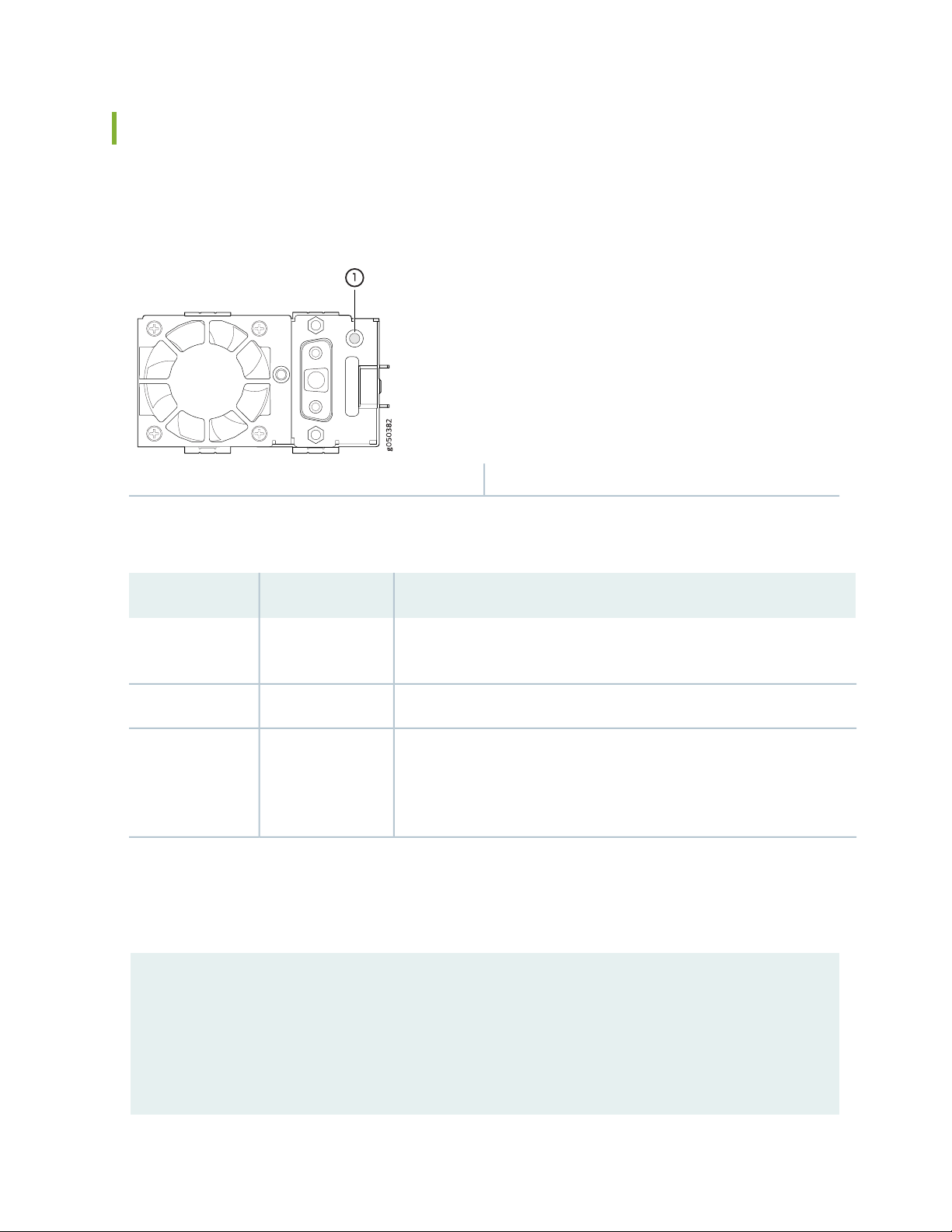
QFX5220-128C DC Power Supply LED
Figure 27 on page 78 shows the location of the status LED on the QFX5220-128C DC power supply.
Figure 27: DC Power Supply LED
1—Status LED
78
Table 23 on page 78 describes the status LED behavior on QFX5220-128C power supplies.
Table 23: DC Power Supply LEDs on a QFX5220-128C
DescriptionStateLED Color
OffUnlit
On steadilyAmber
The power supply is disconnected from power, or power is not coming
into the power supply.
The power supply is operating correctly.On steadilyGreen
A power supply fault or error has occurred in the power supply. Replace
the power supply as soon as possible. To maintain proper airflow through
the chassis, leave the power supply installed in the chassis until you are
ready to replace it.
You can get additional information about the status of the power modules using the show chassis
environment pem. For example:
user@device> show chassis environment pem
PSM1 status:
State Online
Page 79

Temperature 25 degrees C / 77 degrees F
g051075
2
1
3
Fans OK
DC Output Failed
PSM3 status:
State Online
Temperature 25 degrees C / 77 degrees F
79
Fans OK
DC Output Failed
QFX5220-32CD-D DC Power Supply LED
Figure 28 on page 79 shows the location of the power supply status LEDs.
Figure 28: QFX5220-32CD-D Status LEDs
3—1— FaultInput OK
2—Output OK
Table 24 on page 80 describes the status LED behavior on QFX5220-32CD power supplies.
Page 80

Table 24: DC Power Supply LEDs on a QFX5220-32CD
DescriptionLED ColorStatus
80
OffInput OK
Amber, on steadilyFault
RELATED DOCUMENTATION
Maintaining the QFX5220 Power System | 155
The power supply is disconnected from power, or power is not coming
into the power supply.
Input voltage is present and is within range.Green, on steadily
The power supply is running at the power limit or is over current.OffOutput OK
The power supply is operating correctly.Green, on steadily
A power supply fault or error has occurred in thepower supply. Replace
the power supply as soon as possible. To maintain proper airflow
through the chassis, leave the power supplyinstalled in the chassis until
you are ready to replace it.
The power supply is not valid. Check the model number.Amber, blinking
Page 81

2
CHAPTER
Site Planning, Preparation, and
Specifications
QFX5220 Site Preparation Checklist | 82
QFX5220 Site Guidelines and Requirements | 83
QFX5220 Network Cable and Transceiver Planning | 92
QFX5220 Management Cable Specifications and Pinouts | 99
Page 82

QFX5220 Site Preparation Checklist
The checklist in Table 25 on page 82 summarizes the tasks you need to perform when preparing a site for
a QFX5220 installation.
Table 25: Site Preparation Checklist
DatePerformed ByFor More InformationItem or Task
Environment
82
Verify that environmental factors such as
temperature and humidity do not exceed
switch tolerances.
Power
power sources and switch installation site.
Calculate the power consumption and
requirements.
Rack or Cabinet
Verify that your rack or cabinet meets the
minimum requirementsfor the installation of
the switch.
“QFX5220 Environmental
Requirements andSpecifications”
on page 84
—Measure the distance between external
“QFX5220 Power System” on
page 64
QFX5220 Rack Requirements
•
on page 89
QFX5220 Cabinet
•
Requirements on page 90
Determining QFX5220Optical
•
Interface Support on page 92
Plan rack or cabinet location, including
required space clearances.
building structure.
Cables
“QFX5220 Clearance
Requirements for Airflow and
Hardware Maintenance” on
page 87
—Secure the rack or cabinet to the floor and
Page 83

Table 25: Site Preparation Checklist (continued)
83
DatePerformed ByFor More InformationItem or Task
Acquire cables and connectors:
Determine the number of cables needed
•
based on your planned configuration.
Review themaximum distance allowed for
•
each cable. Choose the length of cable
based on the distance between the
hardware components being connected.
“Determining QFX5220 Optical
Interface Support” on page 92
—Plan the cable routing and management.
RELATED DOCUMENTATION
General Safety Guidelines and Warnings | 199
QFX5220 Installation Overview | 111
QFX5220 Site Guidelines and Requirements
IN THIS SECTION
QFX5220 Environmental Requirements and Specifications | 84
General Site Guidelines | 85
QFX5220 Grounding Cable and Lug Specifications | 86
QFX5220 Clearance Requirements for Airflow and Hardware Maintenance | 87
QFX5220 Chassis Physical Specifications | 88
Site Electrical Wiring Guidelines | 88
QFX5220 Rack Requirements | 89
QFX5220 Cabinet Requirements | 90
Page 84

QFX5220 Environmental Requirements and Specifications
The switch must be installed in a rack or cabinet. It must be housed in a dry, clean, well-ventilated, and
temperature-controlled environment.
Follow these environmental guidelines:
The site must be as dust-free as possible, because dust can clog air intake vents and filters, reducing the
•
efficiency of the switch cooling system.
Maintain ambient airflow for normal switch operation. If the airflow is blocked or restricted, or if the
•
intake air is too warm, the switch might overheat, leading to the switch temperature monitor shutting
down the device to protect the hardware components.
Table 26 on page 84 provides the required environmental conditions for normal switch operation.
Table 26: QFX5220-32CD Switch Environmental Tolerances
ToleranceDescription
84
Altitude
Relative humidity, operating
QFX5220-128C-AFO–At 32° F through 104° F (0° C through 40° C)
•
there is no performance degradation to 6000 feet (1828.8 meters
QFX5220-32CD-AFO–At 32° F through 104° F (0° C through 40° C)
•
there is no performance degradation to 6000 feet (1828.8 meters)
QFX5220-32CD-AFI-At 32° F through 77° F (0° C through 25° C) there
•
is no performance degradation to 6000 feet (1828.8 meters)
Normal operation ensured in relative humidity range of 5% through 90%,
noncondensing
Page 85

Table 26: QFX5220-32CD Switch Environmental Tolerances (continued)
ToleranceDescription
85
Temperature
Seismic
QFX5220-128C-AFO
Normal operation ensured in temperature range of 32° F through 104° F
•
(0° C through 40° C)
Nonoperating storagetemperature in shipping container: –40° F through
•
158° F (–40° C through 70° C)
QFX5220-32CD-AFO
Normal operation ensured in temperature range of 32° F through 104° F
•
(0° C through 40° C)
Nonoperating storagetemperature in shipping container: –40° F through
•
158° F (–40° C through 70° C)
QFX5220-32CD-AFI
Normal operation ensured in temperature range of 32° F through 77° F
•
(0° C through 25° C)
Nonoperating storagetemperature in shipping container: –40° F through
•
158° F (–40° C through 70° C)
Designed to comply with Zone 4 earthquake requirements per NEBS
GR-63-CORE, Issue 3.
General Site Guidelines
Efficient deviceoperation requires proper site planningand maintenance andproper layoutof the equipment,
rack or cabinet, and wiring closet.
To plan and create an acceptable operating environment for your device and prevent environmentally
caused equipment failures:
Keep the area around the chassis free from dust and conductive material, such as metal flakes.
•
Follow prescribed airflow guidelines to ensure that the cooling system functions properly and that
•
exhaust from other equipment does not blow into the intake vents of the device.
Follow the prescribed electrostatic discharge (ESD) prevention procedures to prevent damaging the
•
equipment. Static discharge can cause components to fail completely or intermittently over time.
Install the device in a secure area, so that only authorized personnel can access the device.
•
Page 86

QFX5220 Grounding Cable and Lug Specifications
For installations that require aseparate grounding conductor to the chassis, the switch mustbe adequately
grounded before power is connected to ensure proper operation and to meet safety and electromagnetic
interference (EMI) requirements. To ground a QFX5220, connect a grounding cable to earth ground and
then attach it to the chassis grounding points.
NOTE: A ground connection to the protectiveearthing terminal is not requiredfor an AC-powered
switch. The AC power cords provide adequate grounding when you connect the power supply
in the switch to a grounded AC power outlet by using the AC power cord appropriate for your
geographical location.
WARNING: The switch is pluggable type A equipment installed in a restricted-access
location. It has a separate protective earthing terminal provided on the chassis in
addition to the grounding pin of the power supply cord. This separate protective
earthing terminal must be permanently connected to earth ground for installations
that require a separate grounding conductor to the chassis.
86
WARNING: To comply with GR-1089 requirements, all intrabuilding copper cabling
used for SFP+ and QSFP+ ports must be shielded and grounded at both ends.
CAUTION: Before switch installation begins,a licensed electrician must attach a cable
lug to the grounding cables that you supply. See “Ground the QFX5220-32CD and
Connect Power” on page 132 and “Ground the QFX5220-128C” on page 129. A cable
with an incorrectly attached lug can damage the switch.
Before connecting the switch to earth ground, review the following information:
The groundinglug required for the protective earthing terminal on aQFX5220 is a Panduit LCD10-10A-L
•
or equivalent(not provided). Thegrounding lug should accommodates 14–10 AWG (2–5.3 mm²) stranded
wire.
The grounding cable that you provide for a QFX5220 must be 14 AWG (2 mm²), minimum 60° C wire,
•
or as permitted by the local code.
Ensure you have two SAE 10-32 x 1/4 in. washers and screws to attach the cable and bracket (not
•
provided).
Page 87

QFX5220 Clearance Requirements for Airflow and Hardware Maintenance
g051087
18.99 in.
(48.23 cm)
Clearance required
for maintenance
22.79 in. (57.88 cm)
FRUsPorts
17.26 in.
(43.84 cm)
Clearance required
for maintenance
21.1 in. (53.59 cm)
30 in. (76.2 cm) 24 in. (61.0 cm)
g051193
FRUs
19.0 in.
(48.23 cm)
Ports
17.32 in.
(44.00 cm)
29.00 in. (73.66 cm)
Clearance required
for maintenance
29.25 in. (74.30 cm)
Clearance required
for maintenance
30 in. (76.2 cm) 24 in. (61.0 cm)
When planning the site for installing a QFX5220, you must allow sufficient clearance around the installed
chassis (see Figure 29 on page 87 and Figure 30 on page 87).
Figure 29: Clearance Requirements for Airflow and Hardware Maintenance for a QFX5220-32CD
87
Figure 30: Clearance Requirements for Airflow and Hardware Maintenance for a QFX5220-128C
For the cooling system to function properly, the airflow around the chassis must be unrestricted. See
•
“QFX5220 Cooling System” on page 55 for more information about the airflow through the chassis.
Page 88

If you are mounting a QFX5220 in a rack or cabinet with other equipment, ensure that the exhaust from
•
other equipment does not blow into the intake vents of the chassis.
Leave at least 24 in. (61 cm) both in front of and behind the QFX5220. For service personnel to remove
•
and install hardware components, you must leave adequate space at the front and back of the switch.
NEBS GR-63 recommends that you allow at least 30 in. (76.2 cm) in front of the rack or cabinet and
24 in. (61 cm) behind the rack or cabinet.
QFX5220 Chassis Physical Specifications
The QFX5220 is a rigid sheet-metal structure that houses the hardware components (see
Table 27 on page 88).
Table 27: Physical Specifications for the QFX5220
WeightDepthWidthHeightProduct Model
88
24.5 lb (11.11 kg) with power
supplies and fans installed
98 lb (44.45 kg) with power
supplies and fans installed
76 lb (34.47 kg) chassis only
QFX5220-128C
1.72 in. (4.3 cm)QFX5220-32CD
cm)
17.26 in.
(43.8 cm)
17.32 in (44 cm)6.88 in. (17.48
21.1 in.
(53.59 cm)
29.25 in. (74.3
cm)
Site Electrical Wiring Guidelines
Table 28 on page 89 describes the factors you must consider while planning the electrical wiring at your
site.
WARNING: You must provide a properlygrounded and shieldedenvironment and use
electrical surge-suppression devices.
Avertissement Vous devez établir un environnement protégé et convenablement mis
à la terre et utiliser des dispositifs de parasurtension.
Page 89

Table 28: Site Electrical Wiring Guidelines
Site Wiring
Factor
Guidelines
89
Signaling
limitations
Radio
frequency
interference
Electromagnetic
compatibility
If yoursite experiences any ofthe following problems, consultexperts in electrical surgesuppression
and shielding:
Improperly installed wires cause radio frequency interference (RFI).
•
Damage fromlightning strikes occurswhen wires exceedrecommended distances orpass between
•
buildings.
Electromagnetic pulses (EMPs) caused by lightning damage unshielded conductors and electronic
•
devices.
To reduce or eliminate RFI from your site wiring, do the following:
Use a twisted-pair cable with a good distribution of grounding conductors.
•
If you must exceed the recommended distances, use a high-quality twisted-pair cable with one
•
ground conductor for each data signal when applicable.
If your site is susceptible to problems with electromagnetic compatibility (EMC), particularly from
lightning or radio transmitters, seek expert advice.
Some of the problems caused by strong sources of electromagnetic interference (EMI) are:
Destruction of the signal drivers and receivers in the device
•
Electrical hazards as a result of power surges conducted over the lines into the equipment
•
QFX5220 Rack Requirements
QFX5220 switches are designed to be installed on four-post racks.
Rack requirements consist of:
Rack type
•
Mounting bracket hole spacing
•
Rack size and strength
•
Table 29 on page 90 provides the rack requirements and specifications for the QFX5220.
Page 90

Table 29: Rack Requirements for the QFX5220
GuidelinesRack Requirement
90
Rack type
Mounting bracket
hole spacing
Rack size and
strength
Use a four-post rack that provides bracket holes or hole patterns spaced at 1-U (1.75 in. or
4.45 cm)increments and that meets the size and strength requirements to support the weight.
A U is the standard rack unit defined in Cabinets, Racks, Panels, and Associated Equipment
(document number EIA-310–D) published by the Electronics Industry Association.
The holes in the mounting brackets are spaced at 1-U (1.75 in. or 4.45 cm) increments, so that
the switch can be mounted in any rack that provides holes spaced at that distance.
Ensure that the rack complies with the standards for a 19-in. or 23-in. rack as defined in
•
Cabinets, Racks, Panels, and Associated Equipment (document number EIA-310–D) published
by the Electronics Industry Association.
A 600-mm rack as defined in the four-part Equipment Engineering (EE); European
•
telecommunications standard for equipment practice (document numbers ETS 300 119-1
through 119-4) published by the European Telecommunications Standards Institute.
The horizontal spacing between the rails in a rack that complieswith this standard is usually
wider than the device's mounting brackets, which measure 19 in. (48.26 cm) from outer
edge to outer edge. Use approved wing devices to narrow the opening between the rails as
required.
Ensure that the rack rails are spaced widely enough to accommodate the switch chassis’
•
external dimensions. The outer edges of the front-mounting brackets extend the width to
19 in. (48.26 cm).
For four-post installations, the front and rear rack rails must be spaced between 23.6 in. (60
•
cm) and 36 in. (91.4 cm) front to back.
The rack must be strong enough to support the weight of the switch.
•
Ensure that the spacing of rails and adjacent racks allows for proper clearance around the
•
switch and rack.
Rack connection to
building structure
Secure the rack to the building structure.
•
If earthquakes are a possibility in your geographical area, secure the rack to the floor.
•
Secure the rack to the ceiling brackets as well as wall or floor brackets for maximum stability.
•
QFX5220 Cabinet Requirements
You can mount the QFX5220 in an enclosure or cabinet that contains a four-post 19-in. open rack as
defined in Cabinets, Racks, Panels, and Associated Equipment (document number EIA-310-D) published by
the Electronics Industry Association.
Page 91

Cabinet requirements consist of:
Cabinet size and clearance
•
Cabinet airflow requirements
•
Table 30 on page 91 provides the cabinet requirements and specifications for the QFX5220.
Table 30: Cabinet Requirements for the QFX5220
GuidelinesCabinet Requirement
91
Cabinet size and clearance
Cabinet airflow requirements
The minimum cabinet size for accommodating a QFX5220 device is 36 in.
(91.4 cm) deep. Large cabinets improve airflow and reduce the chance of
overheating.
When you mount the switch in a cabinet, ensure thatventilation through the
cabinet is sufficient to prevent overheating.
Ensure that the cool air supply youprovide through thecabinet adequately
•
dissipates the thermal output of the switch (or switches).
Ensure that the cabinet allows the chassishot exhaust air to exit the cabinet
•
without recirculating into the switch. An open cabinet (without a top or
doors) that employs hot air exhaust extractionfrom the top allows the best
airflow through the chassis. If the cabinet contains a top or doors,
perforations in these elements assist with removing the hot air exhaust.
The QFX5220 fans exhaust hot air either through the vents on the port
•
panel or through the fans and power supplies. Install the switch in the
cabinet in a way that maximizes the open space on the FRU side of the
chassis. This maximizes the clearance for critical airflow.
Route and dress all cables to minimize the blockage of airflow to and from
•
the chassis.
Ensure thatthe spacing ofrails and adjacent cabinetsallows for theproper
•
clearance around the switch and cabinet.
RELATED DOCUMENTATION
QFX5220 Installation Overview | 111
Unpacking and Mounting the QFX5220 | 112
Page 92

QFX5220 Network Cable and Transceiver Planning
IN THIS SECTION
Determining QFX5220 Optical Interface Support | 92
Cable Specifications for QSFP+ and QSFP28 Transceivers | 93
Understanding QFX Series Fiber-Optic Cable Signal Loss, Attenuation, and Dispersion | 95
Calculating Power Budget and Power Margin for Fiber-Optic Cables | 96
Determining QFX5220 Optical Interface Support
92
You can find information about the optical transceivers supported on your Juniper device by using the
Hardware Compatibility Tool. In addition to transceiver and connection type, the optical and cable
characteristics–where applicable–are documented for each transceiver. The Hardware Compatibility Tool
enables you to search by product, displaying all the transceivers supported on that device, or category, by
interface speed or type. The list of supported transceivers for the QFX5220 is located at
https://apps.juniper.net/hct/product/#prd=QFX5220.
CAUTION: If you face a problem running a Juniper Networks device that uses a
third-party optic or cable, the Juniper Networks Technical Assistance Center (JTAC)
can helpyou diagnose thesource of the problem. YourJTAC engineer mightrecommend
that you check thethird-party optic or cable and potentially replaceit with an equivalent
Juniper Networks optic or cable that is qualified for the device.
NOTE: For interoperability with other QFX Series switches, ensure autonegotiation on the
QFX5220 is disabled.
Page 93

Cable Specifications for QSFP+ and QSFP28 Transceivers
The 40-Gigabit Ethernet QSFP+ and 100-Gigabit Ethernet QSFP28 transceivers that are used in QFX
Series switches use 12-ribbon multimode fiber crossover cables with socket MPO/UPC connectors. The
fiber can be either OM3 or OM4. These cables are not sold by Juniper Networks.
CAUTION: To maintain agency approvals, use only a properly constructed, shielded
cable.
TIP: Ensure that you order cables with the correct polarity. Vendors refer to these crossover
cables as key up to key up, latch up to latch up, Type B, or Method B. If you are using patch panels
between two QSFP+ or QSFP28 transceivers, ensure that the proper polarity is maintained
through the cable plant.
93
Table 31 on page 93 describes the signals on each fiber. Table 32 on page 94 shows the pin-to-pin
connections for proper polarity.
Table 31: QSFP+ and QSFP28 Optical Module Receptacle Pinouts
SignalFiber
Tx0 (Transmit)1
Tx1 (Transmit)2
Tx2 (Transmit)3
Tx3 (Transmit)4
Unused5
Unused6
Unused7
Unused8
Rx3 (Receive)9
Rx2 (Receive)10
Page 94

Table 31: QSFP+ and QSFP28 Optical Module Receptacle Pinouts (continued)
SignalFiber
Rx1 (Receive)11
Rx0 (Receive)12
Table 32: QSFP+ MPO Fiber-Optic Crossover Cable Pinouts
PinPin
121
112
103
94
94
85
76
67
58
49
310
211
112
Page 95

Understanding QFX Series Fiber-Optic Cable Signal Loss, Attenuation, and Dispersion
IN THIS SECTION
Signal Loss in Multimode and Single-Mode Fiber-Optic Cables | 95
Attenuation and Dispersion in Fiber-Optic Cable | 95
To determine the power budget and power margin needed for fiber-optic connections, you need to
understand how signal loss, attenuation, and dispersion affect transmission. The QFX Series uses various
types of network cables, including multimode and single-mode fiber-optic cables.
95
Signal Loss in Multimode and Single-Mode Fiber-Optic Cables
Multimode fiber is large enough in diameter to allow rays of light to reflect internally (bounce off the walls
of the fiber). Interfaces with multimode optics typically use LEDs as light sources. However, LEDs are not
coherent light sources. They spray varying wavelengths of light into the multimode fiber, which reflect
the light at different angles. Light rays travel in jagged lines through a multimode fiber, causing signal
dispersion. When light traveling in the fiber core radiates into the fiber cladding (layers of lower refractive
index material in close contact with a core material of higher refractive index), higher-order mode loss
occurs. Together, these factors reduce the transmission distance of multimode fiber compared to that of
single-mode fiber.
Single-mode fiber is sosmall indiameter that rays of light reflect internally through one layer only.Interfaces
with single-mode optics use lasers as light sources. Lasers generate a single wavelength of light, which
travels in a straight line through the single-mode fiber. Compared to multimode fiber, single-mode fiber
has a higher bandwidth and can carry signals for longer distances. It is consequently more expensive.
For information about the maximum transmission distance and supported wavelength range for the types
of single-mode and multimode fiber-optic cables that are connected to the QFX Series, see the Hardware
Compatibility Tool. Exceeding the maximum transmission distances can result in significant signal loss,
which causes unreliable transmission.
Attenuation and Dispersion in Fiber-Optic Cable
An optical data link functions correctly provided that modulated light reaching the receiver has enough
power to be demodulated correctly. Attenuation is the reduction in strength of the light signal during
transmission. Passive media components such as cables, cable splices, and connectors cause attenuation.
Although attenuation is significantly lower for optical fiber than for other media, it still occurs in both
Page 96

multimode and single-mode transmission. An efficient optical data link must transmit enough light to
overcome attenuation.
Dispersion is the spreading of the signal over time. The following two types of dispersion can affect signal
transmission through an optical data link:
Chromatic dispersion, which is the spreading of the signal over time caused by the different speeds of
•
light rays.
Modal dispersion, which is the spreading of the signal over time caused by the different propagation
•
modes in the fiber.
For multimode transmission, modal dispersion, rather than chromatic dispersion or attenuation, usually
limits the maximum bit rate and link length. For single-mode transmission, modal dispersion is not a factor.
However, at higher bitrates and over longer distances, chromatic dispersionlimits the maximum link length.
An efficient optical data link must have enough light to exceed the minimum power that the receiver
requires to operate within its specifications. In addition, the total dispersion must be within the limits
specified for the type of link in the Telcordia Technologies document GR-253-CORE (Section 4.3) and
International Telecommunications Union (ITU) document G.957.
96
When chromatic dispersion is at the maximum allowed, its effect can be considered as a power penalty in
the power budget. The optical power budget must allow for the sum of component attenuation, power
penalties (including those from dispersion), and a safety margin for unexpected losses.
Calculating Power Budget and Power Margin for Fiber-Optic Cables
Use the information in this topic and the specifications for your optical interface to calculate the power
budget and power margin for fiber-optic cables.
TIP: You can use the Hardware Compatibility Tool to find information about the pluggable
transceivers supported on your Juniper Networks device.
To calculate the power budget and power margin, perform the following tasks:
1.
How to Calculate Power Budget for Fiber-Optic Cable | 97
2.
How to Calculate Power Margin for Fiber-Optic Cable | 97
Page 97

How to Calculate Power Budget for Fiber-Optic Cable
To ensure that fiber-optic connections have sufficient power for correct operation, you need to calculate
the link's power budget, which is the maximum amount of power it can transmit. When you calculate the
power budget, you use a worst-case analysis to provide a margin of error, even though all the parts of an
actual system do not operate at the worst-case levels. To calculate the worst-case estimate of power
budget (PB), you assume minimum transmitter power (PT) and minimum receiver sensitivity (PR):
97
PB= PT– P
R
The following hypothetical power budget equation uses values measured in decibels (dB) and decibels
referred to one milliwatt (dBm):
PB= PT– P
R
PB= –15 dBm – (–28 dBm)
PB= 13 dB
How to Calculate Power Margin for Fiber-Optic Cable
After calculating a link's power budget, you can calculate the power margin (PM), which represents the
amount of power available after subtracting attenuation or link loss (LL) from the power budget (PB). A
worst-case estimate of PMassumes maximum LL:
PM= PB– LL
PMgreater than zero indicates that the power budget is sufficient to operate the receiver.
Factors that can cause link loss include higher-order mode losses, modal and chromatic dispersion,
connectors, splices, and fiber attenuation. Table 33 on page 97 lists an estimated amount of loss for the
factors used in the following sample calculations. For information about the actual amount of signal loss
caused by equipment and other factors, refer to vendor documentation.
Table 33: Estimated Values for Factors Causing Link Loss
Estimated Link-Loss ValueLink-Loss Factor
Higher-order mode losses
Modal and chromatic dispersion
Single mode—None
Multimode—0.5 dB
Single mode—None
Multimode—None, if product of bandwidth and distance is less than
500 MHz-km
Page 98

Table 33: Estimated Values for Factors Causing Link Loss (continued)
Estimated Link-Loss ValueLink-Loss Factor
0.5 dBConnector
0.5 dBSplice
98
Fiber attenuation
Single mode—0.5 dB/km
Multimode—1 dB/km
The following sample calculation for a 2-km-long multimode link with a power budget (PB) of 13 dB uses
the estimated values from Table 33 on page 97 to calculate link loss (LL) as the sum of fiber attenuation
(2 km @ 1 dB/km, or 2 dB) and loss for five connectors (0.5 dB per connector, or 2.5 dB) and two splices
(0.5 dB per splice, or 1dB) aswell as higher-order mode losses (0.5 dB). The power margin (PM) is calculated
as follows:
PM= PB– LL
PM= 13 dB – 2 km (1 dB/km) – 5 (0.5 dB) – 2 (0.5 dB) – 0.5 dB
PM= 13 dB – 2 dB – 2.5 dB – 1 dB – 0.5 dB
PM= 7 dB
The following sample calculation for an 8-km-long single-mode link with a power budget (PB) of 13 dB
uses the estimated valuesfrom Table 33 on page 97 to calculate link loss (LL) as thesum of fiber attenuation
(8 km @ 0.5 dB/km, or 4 dB) and loss for seven connectors (0.5 dB per connector, or 3.5 dB). The power
margin (PM) is calculated as follows:
PM= PB– LL
PM= 13 dB – 8 km (0.5 dB/km) – 7(0.5 dB)
PM= 13 dB – 4 dB – 3.5 dB
PM= 5.5 dB
In both examples, the calculated power margin is greater than zero, indicating that the link has sufficient
power for transmission and does not exceed the maximum receiver input power.
RELATED DOCUMENTATION
Maintaining Transceivers and Fiber Optic Cables on a QFX5220 | 161
Page 99

QFX5220 Management Cable Specifications and Pinouts
IN THIS SECTION
Cable Specifications for Console and Management Connections for the QFX Series | 99
RJ-45 Management Port Connector Pinout Information | 100
Console Port Connector Pinouts for the QFX Series | 100
QSFP-DD Port Connector Pinout Information | 101
QSFP+, QSFP28, and QSFP56 Port Connector Pinout Information | 105
SFP, SFP+, and SFP28 Port Connector Pinout Information | 107
USB Port Specifications for the QFX Series | 108
99
Cable Specifications for Console and Management Connections for the QFX Series
Table 34 on page 99 lists the specifications for the cables that connect the QFX Series switch to a
management device.
NOTE: The QFX Series canbe configured with SFP management ports that support1000BASE-SX
transceivers. See the Hardware Compatibility Tool for more on the fiber-optic cables required
for use with these transceivers.
Table 34: Cable Specifications for Console and Management Connections for the QFX Series
Port on QFX
Series Device
Console port
RS-232 (EIA-232) serial
cable
One 7-foot(2.13-meter) long
RJ-45 patch cable and RJ-45
to DB-9 adapter
Maximum
LengthCable SuppliedCable Specification
(2.13 meters)
Device
Receptacle
RJ-457 feet
Page 100

Table 34: Cable Specifications for Console and Management Connections for the QFX Series (continued)
100
Port on QFX
Series Device
Management port
Category 5 cable or
equivalent suitable for
1000BASE-T operation
One 7-foot(2.13-meter) long
RJ-45 patch cable
Maximum
LengthCable SuppliedCable Specification
(100 meters)
Device
Receptacle
RJ-45328 feet
RJ-45 Management Port Connector Pinout Information
Table 35 on page 100 provides the pinout information for the RJ-45 connector for the management port
on Juniper Networks devices.
Table 35: RJ-45 Management Port Connector Pinout Information
DescriptionSignalPin
Transmit/receive data pair 1TRP1+1
Transmit/receive data pair 1TRP1—2
Transmit/receive data pair 2TRP2+3
Transmit/receive data pair 3TRP3+4
Transmit/receive data pair 3TRP3—5
Transmit/receive data pair 2TRP2—6
Transmit/receive data pair 4TRP4+7
Transmit/receive data pair 4TRP4—8
Console Port Connector Pinouts for the QFX Series
The console port (labeled CON, or CONSOLE) is an RS-232 serial interface that uses an RJ-45 connector
to connect to a console management device. The default baud rate for the console port is 9600 baud.
 Loading...