

Page 1

Quick Start Guide
QFX5200-32C and QFX5200-32C-L Quick Start Guide
IN THIS GUIDE
System Overview | 1
Tools and Parts Required for Installation | 2
Part 1, Mounting the Switch into a 4 Post Rack | 3
Part II. Ground the Chassis and Connect Power | 5
Connect Power to the Switch | 5
Part III. Connect the QFX5200-32C or QFX5200-32C-L to the Nework and Perform Initial Configuration | 6
QFX5200-32C and QFX5200-32C-L Safety Warning Summary | 8
System Overview
The Juniper Networks QFX5200-32C and QFX5200-32C-L are compact 1 U standalone Ethernet switches that provides
a line rate configuration packet performance, very low latency, and a rich set of Layer 3 features. The routing engine and
control plane are driven by the 1.8 Ghz quad-core Intel CPU with 16 GB of memory and two 32 GB solid-state drives
(SSD) for storage.
The QFX5200-32C and QFX5200-32C-L comes standard with redundant fans and redundant power supplies. Switches
can be ordered with either ports-to-FRUs or FRUs-to-ports airflow. The QFX5200-32C is available with AC or DC power
supplies; the QFX5200-32C-L is available only with AC power supplies.
The QFX5200-32C models run standard Junos Operating System (OS) and is supported as a standalone switch, (Junos
OS Release 15.1X53-D30 and later), a member in a QFX5200-32C Virtual Chassis (Junos OS Release 17.3R2 and later,
or as a; satellite device in a Junos Fusion Provider Edge system (Junos OS Release 18.1R1and later). The QFX5200-32C-L
models run Junos OS Evolved and is supported as a standalone switch (Junos OS Evolved Release 18.3R1 and later).
Page 2

Tools and Parts Required for Installation
TIP: The Quick Start Guide is designed to show the basic installation and startup procedures. For complete
instructions see the QFX5200 Hardware Guide at QFX5200 Switch Hardware Guide
Gather the tools and equipment listed in Table 1 for installing the switch in a 4 post rack.
Table 1: Tools and Equipment Needed to Install QFX5200-32C and QFX5200-32C-L
Provided/NotTools and Equipment
Not providedElectrostatic discharge (ESD) grounding strap
Not providedA Phillips (+) screwdriver, number 2
ProvidedOne pair of rear mounting blades
2
ProvidedOne pair of front mounting rails
ProvidedTwelve crews to secure the mounting rails to the chassis
Not providedEight screws to secure the chassis and rear installation blades to the rack
Not providedGrounding lug, Panduit LCD10-10A-L or equivalent, two 10-32 x 0.25 screws with #10
split-lock washers to secure the grounding lug to the grounding lug bracket protective earthing
terminal
ProvidedTwo power cords with plugs appropriate to your geographical location
ProvidedRJ-45 cable and RJ-45 to DB-9 serial port adapter
Not ProvidedA Management host, such as a laptop or PC, with an Ethernet port
ProvidedAn Ethernet cable with an RJ-45 connector attached
Register product serial numbers on the Juniper Networks website and update the installation base data if there is any
addition or change to the installation base or if the installation base is moved. Juniper Networks will not be held accountable
for not meeting the hardware replacement service-level agreement for products that do not have registered serial numbers
or accurate installation base data.
Register your product(s) at https://tools.juniper.net/svcreg/SRegSerialNum.jsp.
Update your install base at https://www.juniper.net/customers/csc/management/updateinstallbase.jsp.
Page 3
Part 1, Mounting the Switch into a 4 Post Rack
The QFX5200-32C and QFX5200-32C-L can only be mounted in a four-post rack configuration. To mount the device in
a 19-inch rack:
1. Attach the ESD grounding strap to your bare wrist and to a site ESD point
WARNING: Ensure that you understand how to prevent ESD damage by proper use of an ESD
grounding strap.
2. Place the rack in its permanent location, allowing adequate clearance for airflow and maintenance, and secure it to the
building structure.
WARNING: If you are mounting multiple units in the rack, mount the heaviest unit at the bottom
and mount the others from bottom to top in order of decreasing weight. The switch weighs
approximately 23.5 lb (10.66 kg). Installing the QFX5200-32C in a rack or cabinet requires two people
to lift the switch and secure it to the rack.
3
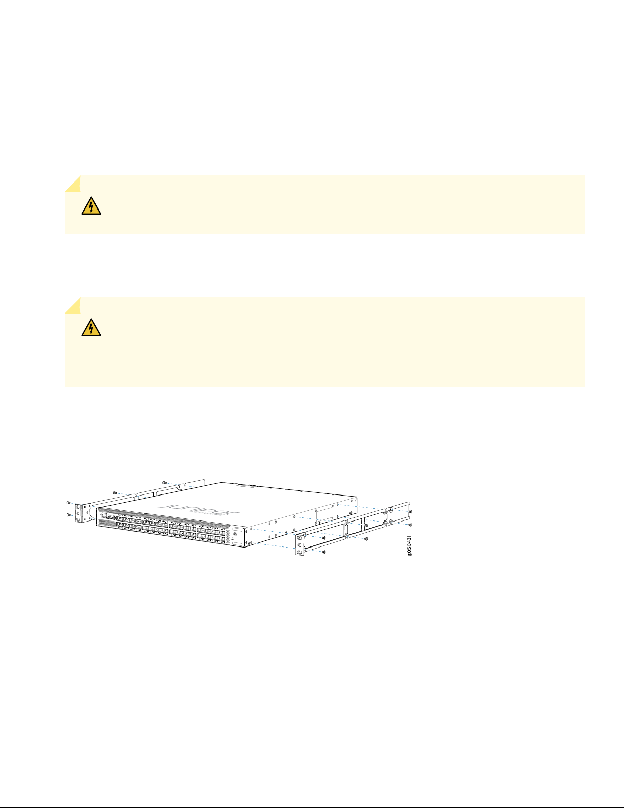
3. Align the holes in the side mounting-rail with the holes on the side of the chassis as shown in Figure 1.
Figure 1: Align Side Mounting-Rail with Chassis Holes
4. Attach the side mounting-rail to the switch using six mounting screws.
5. Repeat steps 3 and 4 on the opposite side of the chassis.
6. Have one person grasp both sides of the switch, lift it, and position it in the rack so that the front bracket is aligned
with the rack holes.
7. Have a second person secure the front of the switch to the rack using four mounting screws (and cage nuts and washers
if your rack requires them.) Tighten the screws
Page 4

Figure 2: Attach Chassis to Rack
g004477
g004478
8. Continue to support the switch while sliding the rear mounting-blades into the channel of the side mounting-rails and
securing the blades to the rack. Use the four mounting screws (and cage nuts and washers if your rack requires them)
to attach each blade to the rack. Tighten the screws.
Figure 3: Slide Mounting Blade into Mounting Rail
4
9. Ensure that the switch chassis is level by verifying that all the screws on the front of the rack are aligned with the
screws at the back of the rack.
Page 5

Part II. Ground the Chassis and Connect Power
To connect earth ground to a QFX5200-32C or QFX5200-32C-L: chassis:
1. Secure the provided protective earthing terminal bracket through the mounting bracket to the chassis with the nut
provided. The posts on the protective earthing terminal bracket should point to the left. See Figure 4.
Figure 4: Connecting a Grounding Cable to a QFX5200-32C and QFX5200-32C-L
2. Connect one end of the grounding cable to a proper earth ground, such as the rack in which the switch is mounted.
5
3. Place the grounding lug attached to the grounding cable over the protective earthing terminal on the protective earthing
terminal bracket.
4. Secure the grounding lug to the protective earthing terminal with two nuts.
5. Dress the grounding cable and ensure that it does not touch or block access to other device components and that it
does not drape where people could trip over it.
Connect Power to the Switch
The QFX5200-32C and QFX5200-32C-L ships with two factory-installed power supplies. The QFX5200-32C-CHAS is a
chassis spare and is shipped without power supplies or fans.
To connect power to an AC-powered chassis:
1. If the AC power source outlet has a power switch, set it to the OFF (0) position.
2. Insert the coupler end of the power cord into the AC power cord inlet on the AC power supply faceplate.
3. Push the power cord retainer onto the power cord.
4. Insert the power cord plug into the power source outlet.
Page 6

5. If the AC power source outlet has a power switch, set it to the ON (|) position.
6. Verify that the AC LEDs are lit green and on steadily.
Part III. Connect the QFX5200-32C or QFX5200-32C-L to the Nework and Perform Initial Configuration
You must perform the initial configuration of the switch through the console port using the CLI or through Zero Touch
Provisioning (ZTP). ZTP is not available for QFX5200-32C-L models.
Before you begin connecting and configuring a QFX5200, set the following parameter values on the console server or
PC:
Baud Rate—9600
•
Flow Control—None
•
6
Data—8
•
Parity—None
•
Stop Bits—1
•
DCD State—Disregard
•
To connect and configure the switch from the console:
1. Connect the console port to a laptop or PC using the supplied RJ-45 cable and RJ-45 to DB-9 adapter. The console
(CON) port is located on the management panel of the switch.
2. Log in as root. There is no password. If the software booted before you connected to the console port, you might need
to press the Enter key for the prompt to appear.
login: root
3. Start the CLI.
root@% cli
4. Enter configuration mode.
root> configure
5. Add a password to the root administration user account.
[edit]
root@# set system root-authentication plain-text-password
Page 7

New password: password
Retype new password: password
6. (Optional) Configure the name of the switch. If the name includes spaces, enclose the name in quotation marks (“ ”).
[edit]
root@# set system host-name host-name
7. Configure the default gateway.
For QFX5200-32C:
•
[edit]
root@# set routing-options static route default next-hop default-gateway-ip-address
For QFX5200-32C-L:
•
[edit]
root@# set system management-instance
root@# set routing-instances mgmt_junos routing-options static route prefix/prefix-length next-hop
7
default-gateway-ip-address
8. Configure the IP address and prefix length for the switch management interface.
For QFX5200-32C systems:
•
[edit]
root@# set interfaces em0 unit 0 family inet address address/prefix-length
For QFX5200-32C-L systems:
•
[edit]
root@# set interfaces re0:mgmt-0 unit 0 family inet address address/prefix-length
CAUTION: Although the CLI permits you to configure two management Ethernet interfaces within
the same subnet, only one interface is usable and supported.
NOTE: On the QFX5200-32C and QFX5200-32C-L, management ports em0 (labeled C0) and em1 (labeled
C1) are found on the FRU end of the switch.
9. (Optional) Configure the static routes to remote prefixes with access to the management port.
[edit]
root@# set routing-options static route remote-prefix next-hop destination-ip retain no-readvertise
Page 8

10. Enable telnet service.
[edit]
root@# set system services telnet
NOTE: When Telnet is enabled, you cannot log in to a QFX5200 switch through Telnet using root credentials.
Root login is allowed only for SSH access.
11. Enable SSH service for root login.
[edit]
root@# set system services SSH
12. Commit the configuration to activate it on the switch.
8
[edit]
root@# commit
QFX5200-32C and QFX5200-32C-L Safety Warning Summary
This is a summary of safety warnings. For a complete list of warnings, including translations, see the QFX5200 hardware
documentation at https://www.juniper.net/documentation/product/en_US/qfx5200.
WARNING: Failure to observe these safety warnings can result in personal injury or death.
Permit only trained and qualified personnel to install or replace switch components
•
Perform only the procedures described in this quick start and the QFX5200 documentation. Other services must be
•
performed only by authorized service personnel.
Before installing the switch, read the planning instructions in the QFX5200 documentation to make sure that the site
•
meets power, environmental, and clearance requirements for the switch.
Before connecting the switch to a power source, read the installation instructions in the QFX5200 documentation.
•
The QFX5200-32C and QFX5200-32C-L weighs approximately 23.5 lb (10.66 kg). Manually installing the QFX5200-32C
•
and QFX5200-32C-L in a rack or cabinet at a height above 60 in. (152.4 cm) requires two people to lift the switch and
install mounting screws. To prevent injury, keep your back straight and lift with your legs, not your back.
Page 9

If the rack or cabinet has stabilizing devices, install them in the rack before mounting or servicing the switch in the rack
•
or cabinet.
Before installing or after removing an electrical component, always place it component-side up on a flat antistatic mat
•
or in an antistatic bag.
Do not work on the switch or connect or disconnect cables during electrical storms
•
Before working on equipment that is connected to power lines, remove jewelry, including rings, necklaces, and watches.
•
Metal objects heat up when connected to power and ground and can cause serious burns or become welded to the
terminals.
Power Cable Warning (Japanese)
WARNING: The attached power cable is only for this product. Do not use the cable for another product.
9
In the event of a hardware failure, please contact Juniper Networks, Inc. to obtain a Return Material Authorization (RMA)
number. This number is used to track the returned material at the factory and to return repaired or new components to
the customer as needed.
For more information about return and repair policies, see the customer support Web page at
https://www.juniper.net/support/guidelines.html.
For product problems or technical support issues, contact the Juniper Networks Technical Assistance Center (JTAC) by
using the Case Manager link at https://www.juniper.net/support/ or at 1-888-314-JTAC (within the United States) or
1-408-745-9500 (from outside the United States).
Juniper Networks, the Juniper Networks logo, Juniper, and Junos are registered trademarks of Juniper Networks, Inc. in the
United States and other countries. All other trademarks, service marks, registered marks, or registered service marks are the
property of their respective owners. Juniper Networks assumes no responsibility for any inaccuracies in this document. Juniper
Networks reserves the right to change, modify, transfer, or otherwise revise this publication without notice. Copyright © 2019
Juniper Networks, Inc. All rights reserved. Rev. 01, January 2019.
 Loading...