

Page 1

QFX5120 Switch Hardware Guide
Published
2021-02-22
Page 2

Juniper Networks, Inc.
1133 Innovation Way
Sunnyvale, California 94089
USA
408-745-2000
www.juniper.net
Juniper Networks, the Juniper Networks logo, Juniper, and Junos are registered trademarks of Juniper Networks, Inc. in
the United States and other countries. All other trademarks, service marks, registered marks, or registered service marks
are the property of their respective owners.
Juniper Networks assumes no responsibility for any inaccuracies in this document. Juniper Networks reserves the right
to change, modify, transfer, or otherwise revise this publication without notice.
QFX5120 Switch Hardware Guide
Copyright © 2021 Juniper Networks, Inc. All rights reserved.
The information in this document is current as of the date on the title page.
ii
YEAR 2000 NOTICE
Juniper Networks hardware and software products are Year 2000 compliant. Junos OS has no known time-related
limitations through the year 2038. However, the NTP application is known to have some difficulty in the year 2036.
END USER LICENSE AGREEMENT
The Juniper Networks product that is the subject of this technical documentation consists of (or is intended for use with)
Juniper Networks software. Use of such software is subject to the terms and conditions of the End User License Agreement
(“EULA”) posted at https://support.juniper.net/support/eula/. By downloading, installing or using such software, you
agree to the terms and conditions of that EULA.
Page 3

Table of Contents
1
About the Documentation | x
Documentation and Release Notes | x
Using the Examples in This Manual | x
Merging a Full Example | xi
Merging a Snippet | xii
Documentation Conventions | xii
Documentation Feedback | xv
Requesting Technical Support | xv
Self-Help Online Tools and Resources | xvi
Creating a Service Request with JTAC | xvi
iii
Overview
QFX5120 System Overview | 18
QFX5120 Switches Hardware Overview | 18
Benefits of the QFX5120 Switch | 19
System Software and Hardware and Software Features | 19
Channelization in QFX5120 Switches | 20
Components on the Front and Rear Panels | 21
Virtual Chassis | 31
QFX5120 Cooling System | 32
QFX5120 Power System | 32
QFX5120 Switch Models and Variants | 33
QFX5120 Switch Hardware and CLI Terminology Mapping | 35
QFX5120 Chassis | 41
Chassis Physical Specifications for QFX5120 Switches | 41
Field-Replaceable Units in QFX5120 Switches | 42
Chassis Status LEDs in QFX5120 Switches | 43
Page 4

LEDs on the Management Port on QFX5120 Switches | 46
Network Port LEDs on QFX5120 Switches | 48
Network Port LEDs on QFX5120-32C Switches | 48
Network Port LEDs on QFX5120-48T Switches | 50
Network Port LEDs on QFX5120-48Y Switches | 52
Network Port LEDs on QFX5120-48YM Switches | 54
QFX5120 Cooling System | 56
Fan Modules for QFX5120 Switches | 56
QFX5120 Models and Airflow Direction | 58
QFX5120 Models with Front-to-Back Airflow | 61
QFX5120 Models with Back-to-Front Airflow | 63
How to Position the Switch | 65
QFX5120 Fan Module Status | 66
iv
QFX5120 Power System | 67
AC Power Supply in QFX5120 Switches | 67
Characteristics of the AC Power Supply for QFX5120 Switches | 68
AC Power Supply Airflow | 71
Power Supply Specifications for AC Power Supplies for QFX5120 Switches | 72
Specifications of the Power Cord for AC Power Supplies for QFX5120 Switches | 74
LEDs on the AC Power Supplies Used in QFX5120 Switches | 76
DC Power Supply in QFX5120 Switches | 79
Characteristics of the DC Power Supply | 79
DC Power Supply Airflow | 83
Power Supply Specifications for DC Power Supplies for QFX5120 Switches | 84
LEDs on the DC Power Supplies Used in QFX5120 Switches | 86
High-Voltage Power Supply for QFX5120-48T Switches | 88
Characteristics of the High-Voltage Power Supply for QFX5120-48T Switches | 89
High-Voltage Power Supply Airflow | 90
Power Supply Specifications for High-Voltage Power Supplies for QFX5120-48T
switches | 91
Specifications of the Power Cord for High-Voltage Power Supply for QFX5120-48T
Switches | 92
LEDs on the High-Voltage Power Supply Used in QFX5120-48T Switches | 96
Page 5

Site Planning, Preparation, and Specifications
2
3
Site Preparation Checklist for QFX5120 Switches | 99
QFX5120 Site Guidelines and Requirements | 100
Environmental Requirements and Specifications for QFX5120 Switches | 101
General Site Guidelines | 102
Site Electrical Wiring Guidelines | 102
Rack Requirements for QFX5120 Switches | 103
Cabinet Requirements for QFX5120 Switches | 104
Clearance Requirements for Airflow and Hardware Maintenance for QFX5120 Switches | 105
QFX5120 Network Cable and Transceiver Planning | 108
Pluggable Transceivers and Direct Attach Cables Supported on QFX5120 Switches | 108
Cable Specifications for QSFP+ and QSFP28 Transceivers on QFX5120 Switches | 109
v
How to Calculate the Fiber-Optic Cable Power Budget for QFX Series Switches | 111
How to Calculate the Fiber-Optic Cable Power Margin for QFX Series Switches | 112
QFX5120 Management Cable Specifications and Pinouts | 113
Console Port Connector Pinout Information | 114
RJ-45 Management Port Connector Pinout Information | 115
RJ-45 to DB-9 Serial Port Adapter Pinout Information | 115
RJ-45 Port, SFP Port, SFP+ Port, QSFP+ Port, and QSFP28 Port Connector Pinout
Information | 116
Initial Installation and Configuration
Unpack and Mount the QFX5120 Switch | 123
Unpack the QFX5120 Switch | 123
Parts Inventory (Packing List) for a QFX5120 Switch | 124
Register Products—Mandatory to Validate SLAs | 125
Mount a QFX5120-32C Switch on a Rack or Cabinet | 126
Mount a QFX5120-48T, QFX5120-48Y, or QFX5120-48YM Switch Flush with the Front Posts
of a Rack or Cabinet | 129
Mount a QFX5120-48T, QFX5120-48Y, or QFX5120-48YM Switch in a Recessed Position
from the Front Posts of a Rack or Cabinet | 134
Page 6

Mount a QFX5120-48YM Switch on a Two-Post Rack | 140
4
Connect the QFX5120 to Power | 142
Connect the QFX5120 Switch to Earth Ground | 142
Connect Power to an AC-Powered QFX5120 Switch | 148
Connect Power to a DC-Powered QFX5120 Switch | 151
Connect Power to a QFX5120-48T Switch Powered by a High-Voltage Power Supply | 156
Connect the QFX5120 to the Network | 159
Install a Transceiver | 159
Install a QSFP28 Transceiver | 162
Connect a Fiber-Optic Cable | 164
Connect the QFX5120 to External Devices | 165
Connect a Device to a Network for Out-of-Band Management | 165
vi
Connect a Device to a Management Console Using an RJ-45 Connector | 166
Connecting 1-PPS and 10-MHz Measurement Devices to the QFX5120 Switch | 167
Configure Junos OS on the QFX5120 | 168
QFX5120 Default Configuration | 168
Connect and Configure a QFX5120 Switch | 169
Maintaining Components
Maintain the QFX5120 Cooling System | 176
Remove a Fan Module from a QFX5120 Switch | 176
Install a Fan Module in a QFX5120 Switch | 178
Maintain the QFX5120 Power System | 180
Remove a Power Supply from a QFX5120 Switch | 181
Install a Power Supply in a QFX5120 Switch | 184
Maintain Transceivers | 187
Remove a Transceiver | 187
Remove a QSFP28 Transceiver | 190
Install a Transceiver | 192
Install a QSFP28 Transceiver | 194
Page 7

Maintain Fiber-Optic Cables | 196
5
6
7
Connect a Fiber-Optic Cable | 196
Disconnect a Fiber-Optic Cable | 197
How to Handle Fiber-Optic Cables | 198
Troubleshooting Hardware
Troubleshoot QFX5120 Components | 201
Alarm Types and Severity Levels | 201
Interface Alarm Messages | 202
Creating an Emergency Boot Device for QFX Series Switches | 203
Chassis Component Alarm Conditions on QFX5120 Switches | 204
Contacting Customer Support and Returning the Chassis or Components
Return a QFX5120 Chassis or Components | 208
vii
How to Return a QFX5120 Switch or Component for Repair or Replacement | 208
Locate the Serial Number on a QFX5120 Switch or Component | 209
List the Switch and Components Details with the CLI | 209
Locate the Chassis Serial Number ID Label on a QFX5120 Switch | 210
Locate the Serial Number ID Labels on FRUs in a QFX5120 Switch | 211
Contact Customer Support to Obtain Return Material Authorization | 217
Pack a QFX5120 Switch or Component for Shipping | 218
Pack a QFX5120 Switch for Shipping | 218
Pack QFX5120 Switch Components for Shipping | 220
Safety and Compliance Information
General Safety Guidelines and Warnings | 223
Definitions of Safety Warning Levels | 224
Qualified Personnel Warning | 227
Warning Statement for Norway and Sweden | 228
Fire Safety Requirements | 228
Fire Suppression | 228
Fire Suppression Equipment | 228
Installation Instructions Warning | 230
Page 8

Chassis and Component Lifting Guidelines | 230
Restricted Access Warning | 232
Ramp Warning | 234
Rack-Mounting and Cabinet-Mounting Warnings | 235
Grounded Equipment Warning | 241
Radiation from Open Port Apertures Warning | 242
Laser and LED Safety Guidelines and Warnings | 243
General Laser Safety Guidelines | 243
Class 1 Laser Product Warning | 244
Class 1 LED Product Warning | 245
Laser Beam Warning | 246
viii
Maintenance and Operational Safety Guidelines and Warnings | 246
Battery Handling Warning | 248
Jewelry Removal Warning | 249
Lightning Activity Warning | 251
Operating Temperature Warning | 252
Product Disposal Warning | 254
General Electrical Safety Guidelines and Warnings | 255
Action to Take After an Electrical Accident | 256
Prevention of Electrostatic Discharge Damage | 257
AC Power Electrical Safety Guidelines | 258
AC Power Disconnection Warning | 260
DC Power Electrical Safety Guidelines | 261
DC Power Disconnection Warning | 262
DC Power Grounding Requirements and Warning | 264
DC Power Wiring Sequence Warning | 266
DC Power Wiring Terminations Warning | 269
Page 9

Multiple Power Supplies Disconnection Warning | 272
TN Power Warning | 273
Agency Approvals for QFX5120 Switches | 273
Compliance Statements for EMC Requirements for the QFX Series | 275
Canada | 275
European Community | 276
Israel | 276
Japan | 277
Korea | 277
Taiwan | 277
United States | 278
Nonregulatory Environmental Standards | 278
ix
Restriction of Hazardous Substances (RoHS) Directive Compliance | 279
Page 10

About the Documentation
IN THIS SECTION
Documentation and Release Notes | x
Using the Examples in This Manual | x
Documentation Conventions | xii
Documentation Feedback | xv
Requesting Technical Support | xv
Use this guide to install hardware and perform initial software configuration, routine maintenance, and
troubleshooting for the QFX5120 switch. After completing the installation and basic configuration
procedures covered in this guide, refer to the Junos OS documentation for information about further
software configuration.
x
Documentation and Release Notes
To obtain the most current version of all Juniper Networks®technical documentation, see the product
documentation page on the Juniper Networks website at https://www.juniper.net/documentation/.
If the information in the latest release notes differs from the information in the documentation, follow the
product Release Notes.
Juniper Networks Books publishes books by Juniper Networks engineers and subject matter experts.
These books go beyond the technical documentation to explore the nuances of network architecture,
deployment, and administration. The current list can be viewed at https://www.juniper.net/books.
Using the Examples in This Manual
If you want to use the examples in this manual, you can use the load merge or the load merge relative
command. These commands cause the software to merge the incoming configuration into the current
candidate configuration. The example does not become active until you commit the candidate configuration.
Page 11

If the example configuration contains the top level of the hierarchy (or multiple hierarchies), the example
is a full example. In this case, use the load merge command.
If the example configuration does not start at the top level of the hierarchy, the example is a snippet. In
this case, use the load merge relative command. These procedures are described in the following sections.
Merging a Full Example
To merge a full example, follow these steps:
1. From the HTML or PDF version of the manual, copy a configuration example into a text file, save the
file with a name, and copy the file to a directory on your routing platform.
For example, copy the following configuration to a file and name the file ex-script.conf. Copy the
ex-script.conf file to the /var/tmp directory on your routing platform.
system {
scripts {
commit {
file ex-script.xsl;
}
}
}
interfaces {
fxp0 {
disable;
unit 0 {
family inet {
address 10.0.0.1/24;
}
}
}
}
xi
2. Merge the contents of the file into your routing platform configuration by issuing the load merge
configuration mode command:
[edit]
user@host# load merge /var/tmp/ex-script.conf
load complete
Page 12

Merging a Snippet
To merge a snippet, follow these steps:
1. From the HTML or PDF version of the manual, copy a configuration snippet into a text file, save the
file with a name, and copy the file to a directory on your routing platform.
For example, copy the following snippet to a file and name the file ex-script-snippet.conf. Copy the
ex-script-snippet.conf file to the /var/tmp directory on your routing platform.
commit {
file ex-script-snippet.xsl; }
2. Move to the hierarchy level that is relevant for this snippet by issuing the following configuration mode
command:
[edit]
user@host# edit system scripts
[edit system scripts]
xii
3. Merge the contents of the file into your routing platform configuration by issuing the load merge
relative configuration mode command:
[edit system scripts]
user@host# load merge relative /var/tmp/ex-script-snippet.conf
load complete
For more information about the load command, see CLI Explorer.
Documentation Conventions
Table 1 on page xiii defines notice icons used in this guide.
Page 13
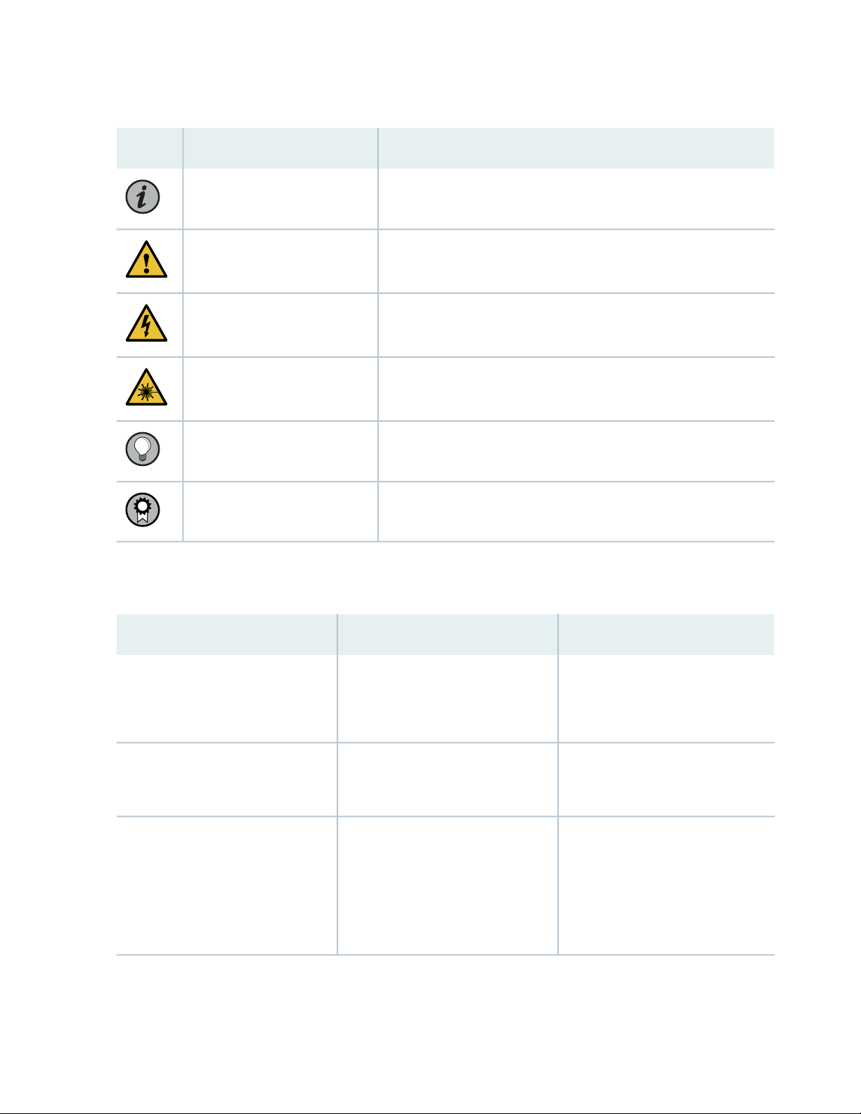
Table 1: Notice Icons
xiii
DescriptionMeaningIcon
Indicates important features or instructions.Informational note
Caution
Indicates a situation that might result in loss of data or hardware
damage.
Alerts you to the risk of personal injury or death.Warning
Alerts you to the risk of personal injury from a laser.Laser warning
Indicates helpful information.Tip
Alerts you to a recommended use or implementation.Best practice
Table 2 on page xiii defines the text and syntax conventions used in this guide.
Table 2: Text and Syntax Conventions
ExamplesDescriptionConvention
Fixed-width text like this
Italic text like this
Represents text that you type.Bold text like this
Represents output that appears on
the terminal screen.
Introduces or emphasizes important
•
new terms.
Identifies guide names.
•
Identifies RFC and Internet draft
•
titles.
To enter configuration mode, type
the configure command:
user@host> configure
user@host> show chassis alarms
No alarms currently active
A policy term is a named structure
•
that defines match conditions and
actions.
Junos OS CLI User Guide
•
RFC 1997, BGP Communities
•
Attribute
Page 14

Table 2: Text and Syntax Conventions (continued)
xiv
ExamplesDescriptionConvention
Italic text like this
Text like this
< > (angle brackets)
| (pipe symbol)
Represents variables (options for
which you substitute a value) in
commands or configuration
statements.
Represents names of configuration
statements, commands, files, and
directories; configuration hierarchy
levels; or labels on routing platform
components.
variables.
Indicates a choice between the
mutually exclusive keywords or
variables on either side of the symbol.
The set of choices is often enclosed
in parentheses for clarity.
Configure the machine’s domain
name:
[edit]
root@# set system domain-name
domain-name
To configure a stub area, include
•
the stub statement at the [edit
protocols ospf area area-id]
hierarchy level.
The console port is labeled
•
CONSOLE.
stub <default-metric metric>;Encloses optional keywords or
broadcast | multicast
(string1 | string2 | string3)
# (pound sign)
[ ] (square brackets)
Indention and braces ( { } )
; (semicolon)
GUI Conventions
Indicates a comment specified on the
same line as the configuration
statement to which it applies.
Encloses a variable for which you can
substitute one or more values.
Identifies a level in the configuration
hierarchy.
Identifies a leaf statement at a
configuration hierarchy level.
rsvp { # Required for dynamic MPLS
only
community name members [
community-ids ]
[edit]
routing-options {
static {
route default {
nexthop address;
retain;
}
}
}
Page 15

Table 2: Text and Syntax Conventions (continued)
xv
ExamplesDescriptionConvention
Bold text like this
> (bold right angle bracket)
Represents graphical user interface
(GUI) items you click or select.
Separates levels in a hierarchy of
menu selections.
In the Logical Interfaces box, select
•
All Interfaces.
To cancel the configuration, click
•
Cancel.
In the configuration editor hierarchy,
select Protocols>Ospf.
Documentation Feedback
We encourage you to provide feedback so that we can improve our documentation. You can use either
of the following methods:
Online feedback system—Click TechLibrary Feedback, on the lower right of any page on the Juniper
•
Networks TechLibrary site, and do one of the following:
Click the thumbs-up icon if the information on the page was helpful to you.
•
Click the thumbs-down icon if the information on the page was not helpful to you or if you have
•
suggestions for improvement, and use the pop-up form to provide feedback.
E-mail—Send your comments to techpubs-comments@juniper.net. Include the document or topic name,
•
URL or page number, and software version (if applicable).
Requesting Technical Support
Technical product support is available through the Juniper Networks Technical Assistance Center (JTAC).
If you are a customer with an active Juniper Care or Partner Support Services support contract, or are
Page 16

covered under warranty, and need post-sales technical support, you can access our tools and resources
online or open a case with JTAC.
JTAC policies—For a complete understanding of our JTAC procedures and policies, review the JTAC User
•
Guide located at https://www.juniper.net/us/en/local/pdf/resource-guides/7100059-en.pdf.
Product warranties—For product warranty information, visit https://www.juniper.net/support/warranty/.
•
JTAC hours of operation—The JTAC centers have resources available 24 hours a day, 7 days a week,
•
365 days a year.
Self-Help Online Tools and Resources
For quick and easy problem resolution, Juniper Networks has designed an online self-service portal called
the Customer Support Center (CSC) that provides you with the following features:
Find CSC offerings: https://www.juniper.net/customers/support/
•
Search for known bugs: https://prsearch.juniper.net/
•
xvi
Find product documentation: https://www.juniper.net/documentation/
•
Find solutions and answer questions using our Knowledge Base: https://kb.juniper.net/
•
Download the latest versions of software and review release notes:
•
https://www.juniper.net/customers/csc/software/
Search technical bulletins for relevant hardware and software notifications:
•
https://kb.juniper.net/InfoCenter/
Join and participate in the Juniper Networks Community Forum:
•
https://www.juniper.net/company/communities/
Create a service request online: https://myjuniper.juniper.net
•
To verify service entitlement by product serial number, use our Serial Number Entitlement (SNE) Tool:
https://entitlementsearch.juniper.net/entitlementsearch/
Creating a Service Request with JTAC
You can create a service request with JTAC on the Web or by telephone.
Visit https://myjuniper.juniper.net.
•
Call 1-888-314-JTAC (1-888-314-5822 toll-free in the USA, Canada, and Mexico).
•
For international or direct-dial options in countries without toll-free numbers, see
https://support.juniper.net/support/requesting-support/.
Page 17

1
CHAPTER
Overview
QFX5120 System Overview | 18
QFX5120 Chassis | 41
QFX5120 Cooling System | 56
QFX5120 Power System | 67
Page 18

QFX5120 System Overview
IN THIS SECTION
QFX5120 Switches Hardware Overview | 18
QFX5120 Switch Models and Variants | 33
QFX5120 Switch Hardware and CLI Terminology Mapping | 35
QFX5120 Switches Hardware Overview
18
IN THIS SECTION
Benefits of the QFX5120 Switch | 19
System Software and Hardware and Software Features | 19
Channelization in QFX5120 Switches | 20
Components on the Front and Rear Panels | 21
Virtual Chassis | 31
QFX5120 Cooling System | 32
QFX5120 Power System | 32
The QFX5120 line of switches delivers low latency, flexible deployment options, and rich automation
features. QFX5120 Switches build a strong underlay foundation for flexible, high-performance,
standards-based fabrics and routing that improve network reliability and agility.
The QFX5120 switch is available in four models—QFX5120-32C, QFX5120-48T, QFX5120-48Y, and
QFX5120-48YM. Each model is available in two variants featuring AC power supplies with front-to-back
or back-to-front airflow and two models featuring DC power supplies with front-to-back or back-to-front
airflow.
For a brief overview of the QFX5120-48T switch, see:
Video: QFX5120-48T Switch Hardware Overview
Page 19

For a brief overview of the QFX5120-48Y switch, see:
Video: QFX5120-48Y Switch Hardware Overview
For a brief overview of the QFX5120-48YM switch, see:
Video: QFX5120-48YM Switch Hardware Overview
Benefits of the QFX5120 Switch
EVPN-VXLAN architecture - QFX5120 Switches support IP fabrics with EVPN-VXLAN overlays, enabling
Layer 2/3 network virtualization.
Hop-by-hop encryption - QFX5120-48YM supports IEEE 802.1AE MACsec AES-256 on all ports to help
secure data center and Ethernet-based DCI/WAN deployments.
Synchronization services – Support for PTP enables QFX5120 to meet the requirements of the financial
services industry (FSI) and the broadcasting media industry.
19
Industry-leading wire speeds—QFX5120 switches offer 25-Gbps and 100-Gbps wire speeds.
Support for channelization—You can channelize the QSFP28 ports and increase the number of interfaces.
Support for Virtual Chassis—QFX5120-32C, QFX5120-48T, and QFX5120-48Y switches support Virtual
Chassis technology. You can interconnect up to two QFX5120-32C, QFX5120-48T, or QFX5120-48Y
switches in a Virtual Chassis configuration.
System Software and Hardware and Software Features
Juniper Networks QFX Series Switches run Junos operating system (Junos OS), which provides Layer 2
and Layer 3 switching, routing, and security services. The first Junos OS release and hardware and software
features supported on the models are listed in Table 3 on page 20.
Page 20

Table 3: First Junos OS Release and Hardware and Software Features Supported on QFX5120 Switch
Models
20
Switch
Model
QFX512032C
QFX512048T
QFX512048Y
QFX512048YM
First Junos OS
Release
Supported
Junos OS
Release
19.1R1
Junos OS
Release
20.2R1
Junos OS
Release
18.3R1
Junos OS
Release
20.4R1
2.2-GHz quad-core Intel CPU
•
16-GB memory
•
64-GB SSD storage
•
2.2-GHz quad-core Intel CPU
•
16-GB memory
•
100-GB SSD storage
•
2.2-GHz quad-core Intel CPU
•
16-GB memory
•
50-GB SSD storage
•
2.9-GHz quad-core Intel CPU
•
16-GB memory
•
100-GB SSD storage
•
Aggregate
Throughput
(Bidirectional)Hardware Features
6.4 Tbps
2.16 Tbps
4 Tbps
4 Tbps
Software Features
Feature-rich automation
•
capabilities with support
for Python, Ansible,
YANG, Chef, and
zero-touch provisioning
(ZTP)
Support for VXLAN as a
•
Layer 2 or Layer 3
gateway and Open
vSwitch Database
(OVSDB) protocol as a
Layer 2 gateway
Advanced Junos OS
•
features such as EVPN,
BGP, MPLS, Layer 3 VPN,
IPv6 Provider Edge (6PE),
telemetry, segment
routing, and MC-LAG
Channelization in QFX5120 Switches
QFX5120 switches support channelization. You can channelize the 100GbE/40GbE quad small form-factor
pluggable (QSFP28) ports into interfaces by connecting breakout cables and by using CLI configuration.
Table 4 on page 21 lists the channelization supported on the models.
Page 21

Table 4: Channelization in QFX5120 Switches
Supported
ChannelizationPort SpeedPortsSwitch Model
21
For More Information
NOTE: On
port 31, you
cannot
configure four
10GbE
interfaces or
four 25GbE
interfaces.
Four 10GbE interfaces40 Gbps0 through 30QFX5120-32C
Four 25GbE interfaces100 Gbps0 through 30
Two 50GbE interfaces100 Gbps0 through 31
Four 10GbE interfaces40 Gbps50 and 51QFX5120-48T
Four 25GbE interfaces100 Gbps50 and 51
Two 50GbE interfaces100 Gbps48 through 53
Channelizing Interfaces on
QFX5120-32C Switches
Channelizing Interfaces on
QFX5120-48T Switches
Components on the Front and Rear Panels
IN THIS SECTION
QFX5120-32C Switches | 22
QFX5120-48T Switches | 23
Four 10GbE interfaces40 Gbps48 through 55QFX5120-48Y
Four 25GbE interfaces100 Gbps48 through 55
Four 10GbE interfaces40 Gbps50 and 52QFX5120-48YM
Four 25GbE interfaces100 Gbps50 and 52
Two 50GbE interfaces100 Gbps50 and 52
Channelizing Interfaces on
QFX5120-48Y Switches
Channelizing Interfaces on
QFX5120-48YM Switches
Page 22
QFX5120-48Y Switches | 26
g051100
432
6 5 37
1
QFX5120-32C
QFX5120-48YM Switches | 28
QFX5120-32C Switches
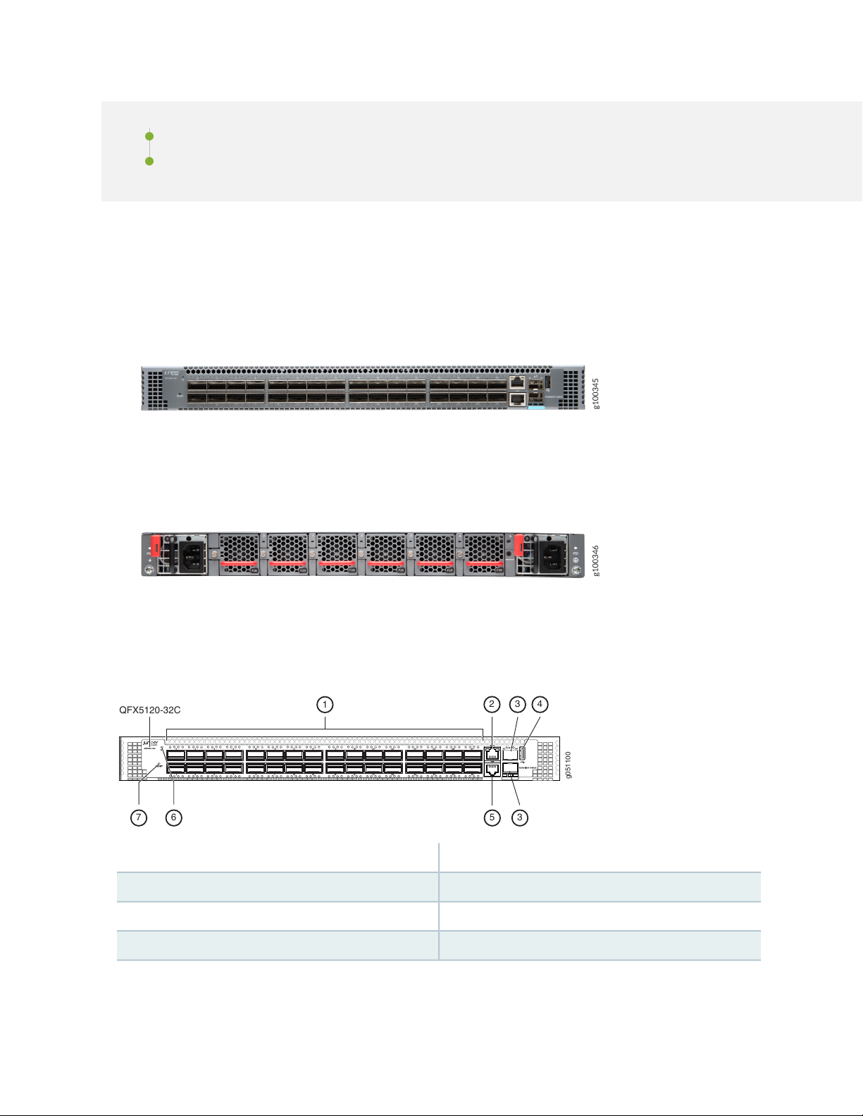
Figure 1 on page 22 shows the front view of the QFX5120-32C switch.
Figure 1: QFX5120-32C—Front View
Figure 2 on page 22 shows the rear view of the QFX5120-32C switch.
22
Figure 2: QFX5120-32C—Rear View
Figure 3 on page 22 shows the components on the front panel of a QFX5120-32C switch.
Figure 3: Components on the Front Panel of a QFX5120-32C Switch
5—1— RJ-45 console port (labeled CON)QSFP28 ports
6—2— Chassis ID LED (labeled ID)RJ-45 management port (labeled MGMT)
7—3— Reset buttonSFP+ ports
4—USB port
Figure 4 on page 23 shows the components on the rear panel of a QFX5120-32C switch with AC power
supplies.
Page 23
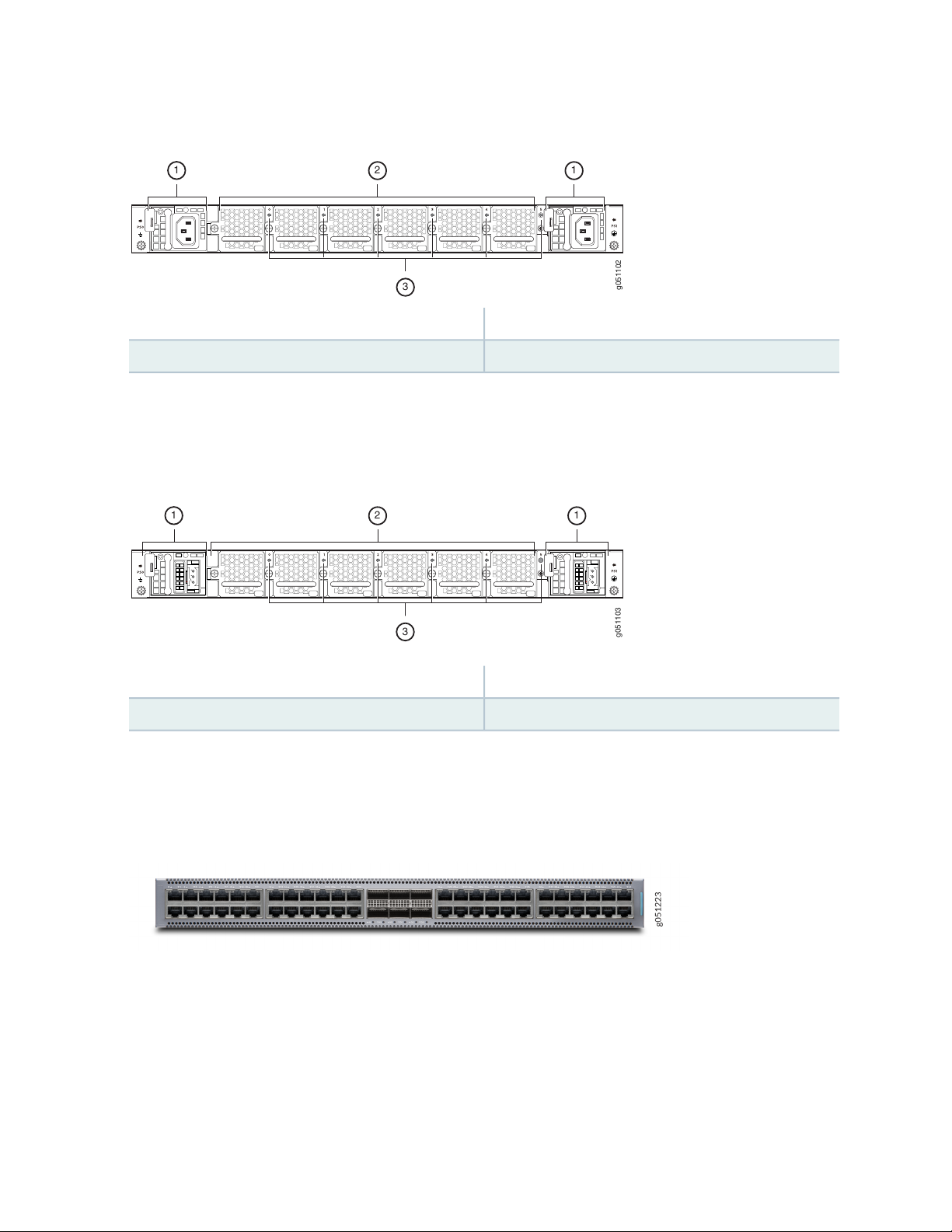
Figure 4: Components on the Rear Panel of a QFX5120-32C Switch with AC Power Supplies
g051102
1
3
2 1
g051103
3
1
2 1
3—1— Fan module LEDsAC power supply
2—Fan modules
Figure 5 on page 23 shows the components on the rear panel of a QFX5120-32C switch with DC power
supplies.
Figure 5: Components on the Rear Panel of a QFX5120-32C Switch with DC Power Supplies
23
3—1— Fan module LEDsDC power supply
2—Fan modules
QFX5120-48T Switches
Figure 6 on page 23 shows the front view of the QFX5120-48T switch.
Figure 6: QFX5120-48T—Front View
Figure 7 on page 24 shows the rear view of the QFX5120-48T switch.
Page 24
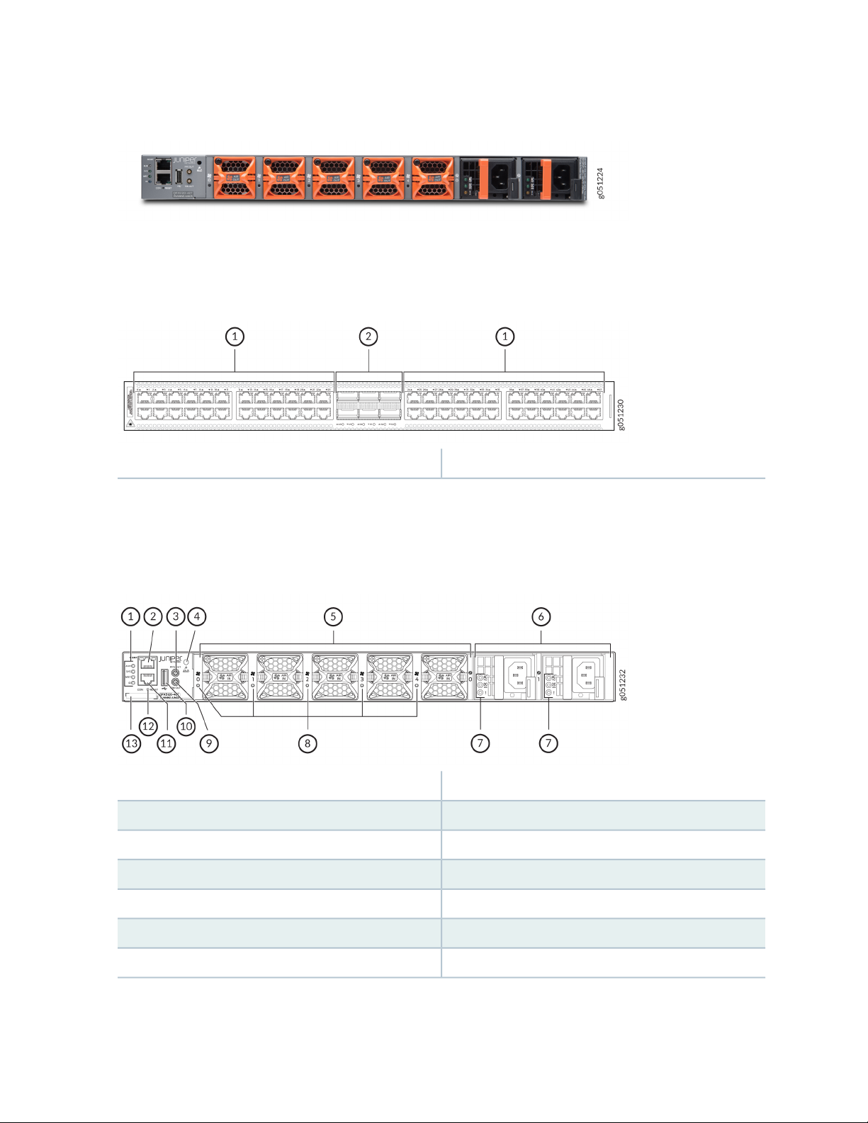
Figure 7: QFX5120-48T—Rear View
Figure 8 on page 24 shows the components on the front panel of a QFX5120-48T switch.
Figure 8: Components on the Front Panel of a QFX5120-48T Switch
2—1— 100GbE/40GbE QSFP28 ports10-Gbps BASE-T ports
24
Figure 9 on page 24 shows the components on the rear panel of a QFX5120-48T switch with AC power
supplies.
Figure 9: Components on the Rear Panel of a QFX5120-48T Switch with AC Power Supplies
8—1— Fan module LEDsChassis status LEDs (labeled ALM, SYS, MST, and ID)
9—2— 10M OUT portRJ-45 management port (labeled MGMT)
10—3— USB portPPS OUT port
11—4— RJ-45 console port (labeled CON)ESD point
12—5— Reset buttonFan modules
7—AC power supply LEDs
13—6— CLEI code labelAC power supplies
Page 25
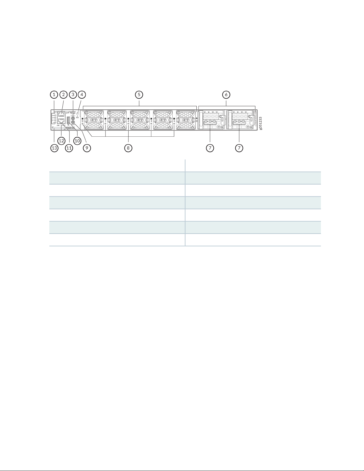
Figure 10 on page 25 shows the components on the rear panel of a QFX5120-48T switch with DC power
supplies.
Figure 10: Components on the Rear Panel of a QFX5120-48T Switch with DC Power Supplies
8—1— Fan module LEDsChassis status LEDs (labeled ALM, SYS, MST, and ID)
9—2— 10M OUT portRJ-45 management port
10—3— USB portPPS OUT port
25
11—4— RJ-45 console portESD point
12—5— Reset buttonFan modules
13—6— CLEI code labelDC power supplies
7—DC power supply LEDs
Figure 11 on page 26 shows the components on the rear panel of a QFX5120-48T switch with high-voltage
power supplies.
Page 26
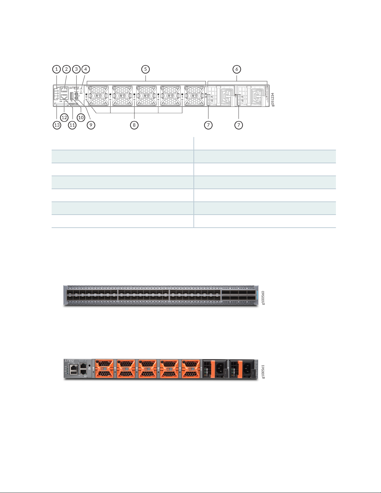
Figure 11: Components on the Rear Panel of a QFX5120-48T Switch with High-Voltage Power Supplies
8—1— Fan module LEDsChassis status LEDs (labeled ALM, SYS, MST, and ID)
9—2— 10M OUT portRJ-45 management port
10—3— USB portPPS OUT port
11—4— RJ-45 console portESD point
12—5— Reset buttonFan modules
26
13—6— CLEI code labelHigh-voltage power supplies
7—High-voltage power supply LEDs
QFX5120-48Y Switches
Figure 12 on page 26 shows the front view of the QFX5120-48Y switch.
Figure 12: QFX5120-48Y—Front View
Figure 13 on page 26 shows the rear view of the QFX5120-48Y switch.
Figure 13: QFX5120-48Y—Rear View
Figure 14 on page 27 shows the components on the front panel of a QFX5120-48Y switch.
Page 27
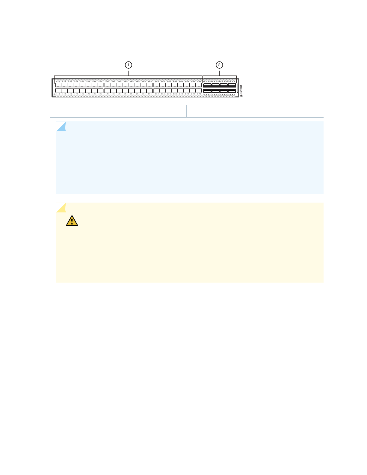
Figure 14: Components on the Front Panel of a QFX5120-48Y Switch
g022500
1 2
2—1— QSFP28 portsSFP28 ports
NOTE:
The SFP28 ports are grouped in quads (groups of four) and you can configure the speed of
•
the ports only in quads; you cannot configure the speed for a single SFP28 port.
The SFP28 ports can operate at 25-Gbps, 10-Gbps, or 1-Gbps speed, based on the configuration
•
set at the quad level. The ports are configured to operate at 10-Gbps speed by default. If you
need the ports to support the other speeds, you must configure those speeds.
27
CAUTION: Do not install 1GbE copper transceivers (such as QFX-SFP-1GE-T) directly
above or below another 1GbE copper transceiver. Use only the top row or bottom
row to avoid damage to the device caused by some types of copper transceivers when
the transceivers are installed above or below each other. However, if you are using
copper transceivers with the OEM part number FCLF8521P2BTL-J1 printed on the
transceiver label, you can install the transceivers in any port with no restrictions. For
devices that support 10GbE copper transceivers, there is no similar restriction.
Figure 15 on page 28 shows the components on the rear panel of a QFX5120-48Y switch with AC power
supplies.
Page 28
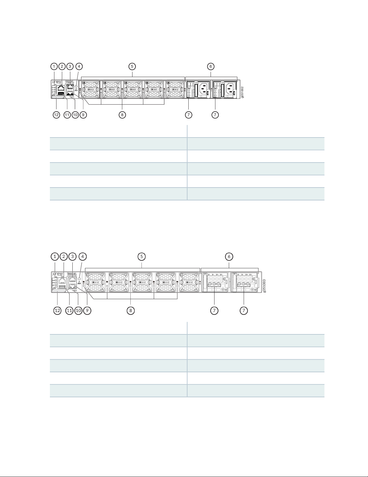
Figure 15: Components on the Rear Panel of a QFX5120-48Y Switch with AC Power Supplies
g051002
1 3 4
5 6
2
12 11 10 89 7 7
7—1— Power supply LEDsChassis status LEDs
8—2— Fan module LEDsRJ-45 console port
9—3— RJ-45 management port (labeled C0)RJ-45 management port (labeled C1)
10—4— Reset buttonESD point
11—5— USB portFan modules
12—6— CLEI code labelPower supplies
28
Figure 16 on page 28 shows the components on the rear panel of a QFX5120-48Y switch with DC power
supplies.
Figure 16: Components on the Rear Panel of a QFX5120-48Y Switch with DC Power Supplies
7—1— Power supply LEDsChassis status LEDs
8—2— Fan module LEDsRJ-45 console port
9—3— RJ-45 management port (labeled C0)RJ-45 management port (labeled C1)
10—4— Reset buttonESD point
11—5— USB portFan modules
QFX5120-48YM Switches
Figure 17 on page 29 shows the front view of the QFX5120-48YM switch.
12—6— CLEI code labelPower supplies
Page 29
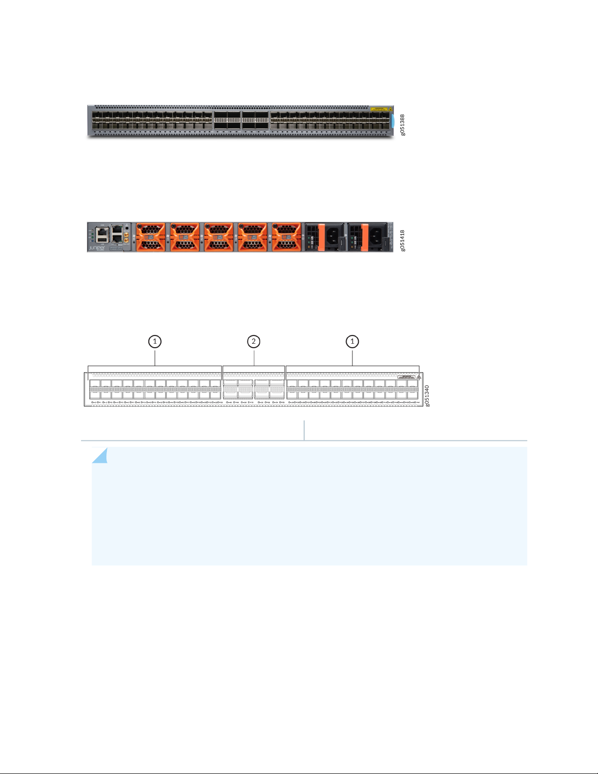
Figure 17: QFX5120-48YM—Front View
Figure 18 on page 29 shows the rear view of the QFX5120-48YM switch.
Figure 18: QFX5120-48YM—Rear View
Figure 19 on page 29 shows the components on the front panel of a QFX5120-48YM switch.
Figure 19: Components on the Front Panel of a QFX5120-48YM Switch
29
2—1— QSFP28 portsSFP28 ports
NOTE:
The SFP28 ports are grouped in quads (groups of four) and you can configure the speed of
•
the ports only in quads; you cannot configure the speed for a single SFP28 port.
The SFP28 ports can operate at 25-Gbps, 10-Gbps, or 1-Gbps speed, based on the configuration
•
set at the quad level. The ports are configured to operate at 10-Gbps speed by default. If you
need the ports to support the other speeds, you must configure those speeds.
Figure 20 on page 30 shows the components on the rear panel of a QFX5120-48YM switch with AC power
supplies.
Page 30
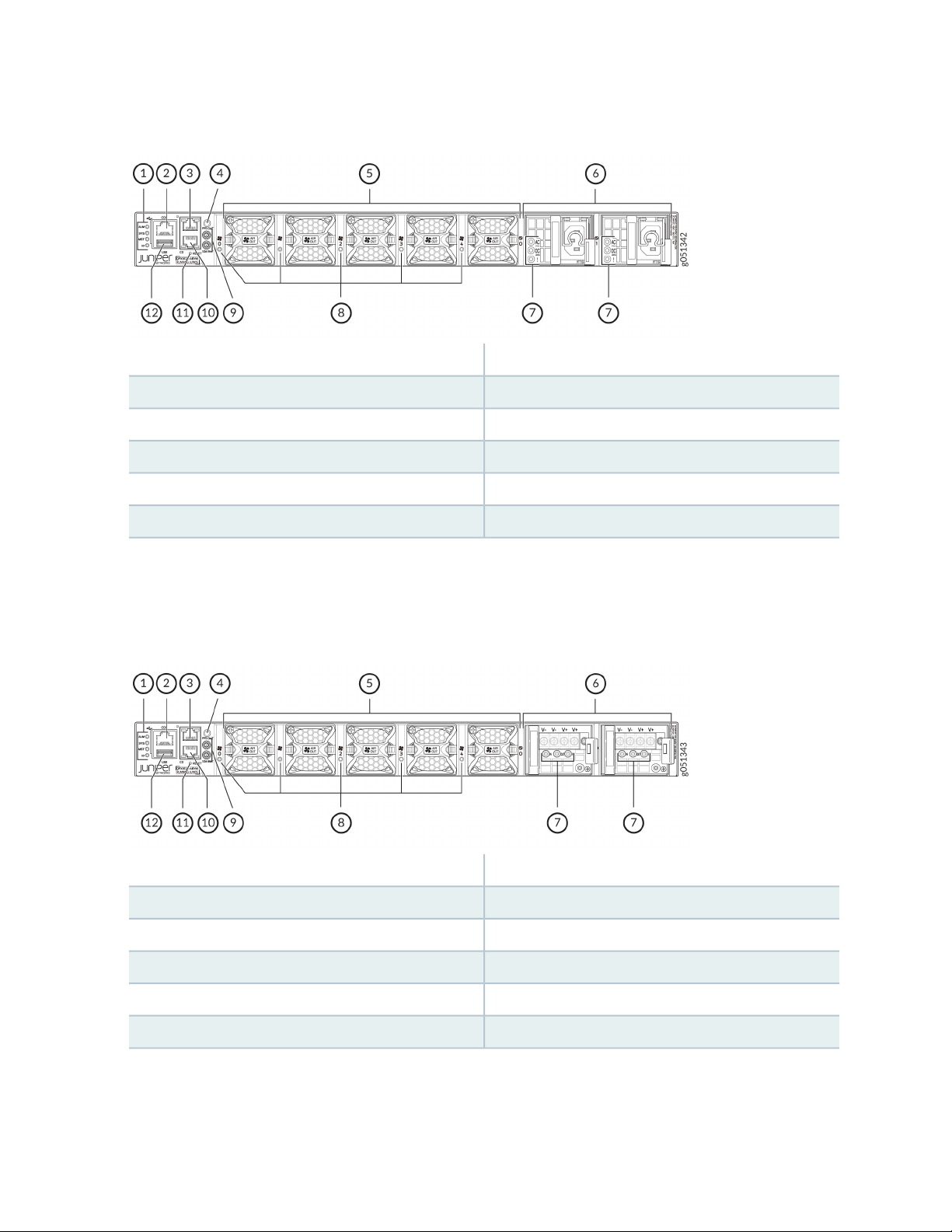
Figure 20: Components on the Rear Panel of a QFX5120-48YM Switch with AC Power Supplies
7—1— Power supply LEDsChassis status LEDs (labeled ALM, SYS, MST, and ID)
8—2— Fan module LEDsRJ-45 console port
9—3— 10M OUT and PPS OUT portsRJ-45 management port (labeled C1)
10—4— RJ-45 management port (labeled C0)ESD point
11—5— Reset buttonFan modules
30
12—6— USB portPower supplies
Figure 21 on page 30 shows the components on the rear panel of a QFX5120-48YM switch with DC
power supplies.
Figure 21: Components on the Rear Panel of a QFX5120-48YM Switch with DC Power Supplies
7—1— Power supply LEDsChassis status LEDs (labeled ALM, SYS, MST, and ID)
8—2— Fan module LEDsRJ-45 console port
9—3— 10M OUT and PPS OUT portsRJ-45 management port (labeled C1)
10—4— RJ-45 management port (labeled C0)ESD point
11—5— Reset buttonFan modules
12—6— USB portPower supplies
The CLEI code label is on the top panel of QFX5120-48YM switches, above the management ports.
Figure 22 on page 31 shows the location of the CLEI code label.
Page 31

Figure 22: Location of the CLEI Code Label on QFX5120-48YM Switches
1—CLEI code label
Virtual Chassis
QFX5120-32C, QFX5120-48T, and QFX5120-48Y switches support Virtual Chassis technology. You can
connect a QX5120 switch only with another QFX5120 switch of the same model in a Virtual Chassis
configuration. QFX5120 switches do not have dedicated or default Virtual Chassis ports (VCPs). However,
you can configure any of the QSFP28 ports as VCPs when those ports are not channelized.
Table 5 on page 31 lists the Junos OS release in which Virtual Chassis support is introduced and the
QSFP28 ports that you can configure as VCPs.
31
Table 5: Virtual Chassis Support in QFX5120 Switches
Support Introduced in
ReleaseModel
Maximum Number of Switches
in the Virtual Chassis
Virtual Chassis Ports
32 QSFP28 ports (0 through 31)2Junos OS Release 20.3R1QFX5120-32C
6 QSFP28 ports (48 through 53)2Junos OS Release 20.2R1QFX5120-48T
8 QSFP28 ports (48 through 55)2Junos OS Release 19.3R1QFX5120-48Y
You configure, monitor, and maintain the QFX5120 Virtual Chassis the same way as you configure, monitor,
and maintain a Virtual Chassis involving other QFX Series switches. See the following topics for more
details on how to configure and change the members in a QFX5120 Virtual Chassis:
Understanding Virtual Chassis Components
•
Removing or Replacing a Member Switch of a Virtual Chassis Configuration
•
Adding a New Switch to an Existing EX4650 or QFX Series Virtual Chassis
•
Virtual Chassis Fabric Overview
•
Page 32

QFX5120 Cooling System
The cooling system in QFX5120 switches consists of fan modules and built-in fans in the power supplies.
The airflow direction depends on the fan modules and power supplies installed in the switch. You can
order a QFX5120 switch that supports front-to-back airflow (air enters through the front of the switch)
or back-to-front airflow (air enters through the back of the switch).
The fan modules are hot-removable and hot-insertable field-replaceable units (FRUs) installed in the rear
panel of the switch: You can remove and replace them without powering off the switch or disrupting
switch functions.
QFX5120 Power System
QFX5120-32C, QFX5120-48T, and QFX5120-48Y switches support two 650-W AC or DC power supplies
with front-to-back or back-to-front airflow. Additionally, QFX5120-48T switches support two 850-W
high-voltage power supplies with AC or DC input and front-to-back or back-to-front airflow.
QFX5120-48YM switches support two 850-W AC or DC power supplies with front-to-back or back-to-front
airflow. Power supplies for the QFX5120 switch are fully redundant, load-sharing, and hot-removable and
hot-insertable FRUs when the second power supply is installed and running. You can remove and replace
them without powering off the switch or disrupting switch functions. Each power supply is cooled by its
own internal cooling system. We ship QFX5120 switches with two AC or DC power supplies preinstalled
in the rear panel of the chassis.
32
CAUTION:
Do not mix:
AC and DC power supplies in the same chassis.
•
650-W and 850-W power supplies in the same QFX5120-48T chassis.
•
Power supplies with different airflow directions in the same chassis.
•
Fan modules with different airflow directions in the same chassis.
•
Power supplies and fan modules with different airflow directions in the same chassis.
•
If you install power supplies or fan modules with different airflow directions, Junos OS
raises an alarm.
Page 33

QFX5120 Switch Models and Variants
The QFX5120 has four models: QFX5120-32C, QFX5120-48T, QFX5120-48Y, and QFX5120-48YM.
Each of these models has variants depending on power supply (AC or DC) and airflow (front-to-back or
back-to-front). All variants of the QFX5120-32C switch ship with two power supplies and six fans installed
by default. All variants of the QFX5120-48T, QFX5120-48Y, and QFX5120-48YM switches ship with two
power supplies and five fans installed by default. Table 6 on page 33 lists the components shipped with
QFX5120 switch models and their variants.
Table 6: QFX5120 Switch Models and Their Configurations
33
Model
Number
QFX512032C-AFO
QFX512032C-AFI
QFX512032C-DC-AFO
QFX512032C-DC-AFI
QFX512048T-AFO
Number of Ports and
Their Types
2 10GbE SFP+
•
32 100GbE/40GbE
•
QSFP28
2 10GbE SFP+
•
32 100GbE/40GbE
•
QSFP28
2 10GbE SFP+
•
32 100GbE/40GbE
•
QSFP28
2 10GbE SFP+
•
32 100GbE/40GbE
•
QSFP28
6 100GbE/40GbE
•
QSFP28
48 10GbE BASE-T
•
Power Supplies Shipped by
Default
Two 650-W AC power supplies
with front-to-back airflow,
indicated by a red ejector lever.
Two 650-W AC power supplies
with back-to-front airflow,
indicated by a blue ejector lever.
Two 650-W DC power supplies
with front-to-back airflow,
indicated by a red ejector lever.
Two 650-W DC power supplies
with back-to-front airflow,
indicated by a blue ejector lever.
Two 650-W AC power supplies
with front-to-back airflow,
indicated by a Juniper Gold ejector
lever.
Fan Modules Shipped by Default
Six fan modules with front-to-back
airflow, indicated by the label F2B
and a red handle.
Six fan modules with back-to-front
airflow, indicated by the label B2F
and a blue handle.
Six fan modules with front-to-back
airflow, indicated by the label F2B
and a red handle.
Six fan modules with back-to-front
airflow, indicated by the label B2F
and a blue handle.
Five fan modules with front-to-back
airflow, indicated by the label AIR
OUT and a Juniper Gold handle.
QFX512048T-AFI
QFX512048T-DC-AFO
6 100GbE/40GbE
•
QSFP28
48 10GbE BASE-T
•
6 100GbE/40GbE
•
QSFP28
48 10GbE BASE-T
•
Two 650-W AC power supplies
with back-to-front airflow,
indicated by a Juniper Azure Blue
ejector lever.
Two 650-W DC power supplies
with front-to-back airflow,
indicated by a Juniper Gold ejector
lever.
Five fan modules with back-to-front
airflow, indicated by the label AIR
IN and a Juniper Azure Blue handle.
Five fan modules with front-to-back
airflow, indicated by the label AIR
OUT and a Juniper Gold handle.
Page 34

Table 6: QFX5120 Switch Models and Their Configurations (continued)
34
Model
Number
QFX512048T-DC-AFI
QFX512048Y-AFO2
QFX512048Y-AFI2
QFX512048Y-DC-AFO2
Number of Ports and
Their Types
6 100GbE/40GbE
•
QSFP28
48 10GbE BASE-T
•
8 100GbE/40GbE
•
QSFP28
48 25GbE/
•
10GbE/1GbE SFP28
8 100GbE/40GbE
•
QSFP28
48 25GbE/
•
10GbE/1GbE SFP28
8 100GbE/40GbE
•
QSFP28
48 25GbE/
•
10GbE/1GbE SFP28
Power Supplies Shipped by
Default
Two 650-W DC power supplies
with back-to-front airflow,
indicated by a Juniper Azure Blue
ejector lever.
Two 650-W AC power supplies
with front-to-back airflow,
indicated by a Juniper Gold ejector
lever.
Two 650-W AC power supplies
with back-to-front airflow,
indicated by a Juniper Azure Blue
ejector lever.
Two 650-W DC power supplies
with front-to-back airflow,
indicated by a Juniper Gold ejector
lever.
Fan Modules Shipped by Default
Five fan modules with back-to-front
airflow, indicated by the label AIR
IN and a Juniper Azure Blue handle.
Five fan modules with front-to-back
airflow, indicated by the label AIR
OUT and a Juniper Gold handle.
Five fan modules with back-to-front
airflow, indicated by the label AIR
IN and a Juniper Azure Blue handle.
Five fan modules with front-to-back
airflow, indicated by the label AIR
OUT and a Juniper Gold handle.
QFX512048Y-DC-AFI2
QFX512048YM-AFO
QFX512048YM-AFI
8 100GbE/40GbE
•
QSFP28
48 25GbE/
•
10GbE/1GbE SFP28
8 100GbE/40GbE
•
QSFP28 that support
Media Access Control
Security (MACsec)
48 25GbE/
•
10GbE/1GbE SFP28
that support MACsec
8 100GbE/40GbE
•
QSFP28 that support
MACsec
48 25GbE/
•
10GbE/1GbE SFP28
that support MACsec
Two 650-W DC power supplies
with back-to-front airflow,
indicated by a Juniper Azure Blue
ejector lever.
Two 850-W AC power supplies
with front-to-back airflow,
indicated by a Juniper Gold ejector
lever.
Two 850-W AC power supplies
with back-to-front airflow,
indicated by a Juniper Azure Blue
ejector lever.
Five fan modules with back-to-front
airflow, indicated by the label AIR
IN and a Juniper Azure Blue handle.
Five fan modules with front-to-back
airflow, indicated by the label AIR
OUT and a Juniper Gold handle.
Five fan modules with back-to-front
airflow, indicated by the label AIR
IN and a Juniper Azure Blue handle.
Page 35

Table 6: QFX5120 Switch Models and Their Configurations (continued)
35
Model
Number
QFX512048YM-DC-AO
QFX512048YM-DC-AI
Number of Ports and
Their Types
8 100GbE/40GbE
•
QSFP28 that support
MACsec
48 25GbE/
•
10GbE/1GbE SFP28
that support MACsec
8 100GbE/40GbE
•
QSFP28 that support
MACsec
48 25GbE/
•
10GbE/1GbE SFP28
that support MACsec
CAUTION:
Do not mix:
Power Supplies Shipped by
Default
Two 850-W DC power supplies
with front-to-back airflow,
indicated by a Juniper Gold ejector
lever.
Two 850-W DC power supplies
with back-to-front airflow,
indicated by a Juniper Azure Blue
ejector lever.
Fan Modules Shipped by Default
Five fan modules with front-to-back
airflow, indicated by the label AIR
OUT and a Juniper Gold handle.
Five fan modules with back-to-front
airflow, indicated by the label AIR
IN and a Juniper Azure Blue handle.
AC and DC power supplies in the same chassis.
•
650-W and 850-W power supplies in the same QFX5120-48T chassis.
•
Power supplies with different airflow directions in the same chassis.
•
Fan modules with different airflow directions in the same chassis.
•
Power supplies and fan modules with different airflow directions in the same chassis.
•
QFX5120 Switch Hardware and CLI Terminology Mapping
This topic describes the hardware terms used in QFX5120 switch documentation and the corresponding
terms used in the Junos OS CLI (see Table 7 on page 36).
Page 36

Table 7: CLI Equivalents of Terms Used in the Documentation for QFX5120 Switches
36
Hardware
Item (CLI)
Chassis
Routing
Engine (n)
QFX5120-
•
32C
QFX5120-
•
48T-CHAS
JNP48Y8C
•
-CHAS
QFX5120-
•
48YM-8C
One of the following:
RE-QFX5120-
•
32C
RE-QFX5120-
•
48T-6C
RE-QFX5120-
•
48Y-8C
RE-QFX5120-
•
48YM-8C
n is a value in the
•
range 0 through
1 for a switch
that is part of a
Virtual Chassis.
On a standalone
•
switch, the
default value is 0.
Item in
DocumentationValueDescription (CLI)
Switch chassis–One of the following:
Additional Information
“QFX5120 Switch
Models and Variants” on
page 33
–Routing Engine
FPC (n)
Abbreviated name of the
Flexible PIC Concentrator
(FPC)
One of the following:
QFX5120
•
-32C
QFX5120
•
-48T-CHAS
JNP48Y8C
•
-CHAS
QFX5120-
•
48YM-8C
n is a value in the
•
range 0 through
1 for a switch
that is part of a
Virtual Chassis.
On a standalone
•
switch, the
default value is 0.
In QFX5120, FPC
refers to the
switch itself.
Understanding Interface
Naming Conventions
Page 37

Table 7: CLI Equivalents of Terms Used in the Documentation for QFX5120 Switches (continued)
37
Hardware
Item (CLI)
Xcvr (n)
Abbreviated name of the
transceiver
n is a value
equivalent to the
number of the port
in which the
transceiver is
installed.
Item in
DocumentationValueDescription (CLI)
Optical
transceivers
Additional Information
“QFX5120 Network
Cable and Transceiver
Planning” on page 108
Page 38

Table 7: CLI Equivalents of Terms Used in the Documentation for QFX5120 Switches (continued)
38
Hardware
Item (CLI)
One of the following:
QFX5120-32C Fan Tray n,
•
Front to Back Airflow AFO
QFX5120-32C Fan Tray n,
•
Back to Front Airflow - AFI
QFX5120-48T
One of the following:
Fan-board Fan Tray n,
•
Front to Back Airflow AFO
Fan-board Fan Tray n, Back
•
to Front Airflow - AFI
n has a value 0
through 5,
corresponding to
the fan module slot
number.
n has a value 0
through 4,
corresponding to
the fan module slot
number.
Item in
DocumentationValueDescription (CLI)
Fan moduleQFX5120-32CFan tray (n)
Additional Information
“QFX5120 Cooling
System” on page 56
QFX5120-48Y
One of the following:
fan-ctrl-n, Front to Back
•
Airflow - AFO
fan-ctrl-n, Back to Front
•
Airflow - AFI
QFX5120-48YM
One of the following:
Fan-board Fan Tray n,
•
Front to Back Airflow AFO
Fan-board Fan Tray n, Back
•
to Front Airflow - AFI
n has a value 0
through 4,
corresponding to
the fan module slot
number.
n has a value 0
through 4,
corresponding to
the fan module slot
number.
Page 39

Table 7: CLI Equivalents of Terms Used in the Documentation for QFX5120 Switches (continued)
39
Hardware
Item (CLI)
Power Supply
(n)
QFX5120-32C
One of the following:
QFX520048Y
•
-650W-AC
-AFI
QFX520048Y
•
-650W-AC
-AFO
QFX5120-48T
One of the following:
JPSU
•
-650W-AC
-AO
JPSU
•
-650W-AC
-AI
JPSU
•
-850W-HV
-AFO
JPSU
•
-850W-HV
-AFI
JPSU
•
-650W-DC
-AFO
JPSU
•
-650W-DC
-AFI
through 1,
corresponding to
the power supply
slot number.
Item in
DocumentationValueDescription (CLI)
Power supplyn has a value 0
Additional Information
“QFX5120 Power
System” on page 67
Page 40

Table 7: CLI Equivalents of Terms Used in the Documentation for QFX5120 Switches (continued)
40
Hardware
Item (CLI)
QFX5120-48Y
One of the following:
JPSU
•
-650W-AC
-AO
JPSU
•
-650W-AC
-AI
JPSU
•
-650W-DC
-AFO
JPSU
•
-650W-DC
-AFI
QFX5120-48YM
Item in
DocumentationValueDescription (CLI)
Additional Information
One of the following:
JPSU
•
-850W-AC
-AFO
JPSU
•
-850W-AC
-AFI
JPSU
•
-850W-DC
-AFO
JPSU
•
-850W-DC
-AFI
Page 41

CAUTION:
Do not mix:
AC and DC power supplies in the same chassis.
•
650-W and 850-W power supplies in the same QFX5120-48T chassis.
•
Power supplies with different airflow directions in the same chassis.
•
Fan modules with different airflow directions in the same chassis.
•
Fan modules and power supplies with different airflow directions in the same chassis.
•
QFX5120 Chassis
41
IN THIS SECTION
Chassis Physical Specifications for QFX5120 Switches | 41
Field-Replaceable Units in QFX5120 Switches | 42
Chassis Status LEDs in QFX5120 Switches | 43
LEDs on the Management Port on QFX5120 Switches | 46
Network Port LEDs on QFX5120 Switches | 48
Chassis Physical Specifications for QFX5120 Switches
The QFX5120 switch chassis is a rigid sheet-metal structure that houses all components of the switch.
Table 8 on page 41 shows the physical specifications of the QFX5120 switch models.
Table 8: Physical Specifications of the QFX5120 Switch Models
WeightDepthWidthHeightModel
QFX5120-32C
(4.33 cm)
17.26 in. (43.84 cm)1.7 in.
20.27 in. (51.5 cm)
excluding fan and power
supply handles
21.12 lb (9.58 kg) with
two power supplies and
fans installed
Page 42

Table 8: Physical Specifications of the QFX5120 Switch Models (continued)
42
WeightDepthWidthHeightModel
QFX5120-48T
QFX5120-48Y
QFX5120-48YM
1.72 in.
(4.37 cm)
1.72 in.
(4.37 cm)
1.72 in.
(4.37 cm)
17.36 in. (44.09 cm)
•
The outer edges of the
•
front-mounting brackets
extend the width to 19 in.
(48.2 cm)
17.36 in. (44.09 cm)
•
The outer edges of the
•
front-mounting brackets
extend the width to 19 in.
(48.2 cm)
17.36 in. (44.09 cm)
•
The outer edges of the
•
front-mounting brackets
extend the width to 19 in.
(48.2 cm)
20.48 in. (52.02 cm)
excluding fan and power
supply handles
20.48 in. (52.02 cm)
excluding fan and power
supply handles
20.48 in. (52.02 cm)
excluding fan and power
supply handles
Field-Replaceable Units in QFX5120 Switches
24.25 lb (11 kg) with
two power supplies and
fans installed
23.7 lb (10.75 kg) with
two power supplies and
fans installed
24.8 lb (11.25 kg) with
two power supplies and
fans installed
Field-replaceable units (FRUs) are components that you can replace at your site. The FRUs in QFX5120
switches are hot-removable and hot-insertable: You can remove and replace them without powering off
the switch or disrupting switch functions. The QFX5120 switches have the following FRUs:
Power supplies
•
Fan modules
•
Transceivers
•
NOTE: Transceivers are not part of the shipping configuration. If you want to purchase any of
these components, you must order them separately.
Page 43

NOTE: If you have a Juniper J-Care service contract, register any addition, change, or upgrade
g051128
1
of hardware components at https://www.juniper.net/customers/support/tools/updateinstallbase/.
Failure to do so can result in significant delays if you need replacement parts. This note does
not apply if you replace existing components with the same type of component.
Chassis Status LEDs in QFX5120 Switches
The rear panel of QFX5120-32C switches has a chassis ID LED labeled ID (see Figure 23 on page 43).
Figure 23: Chassis ID LED on a QFX5120-32C Switch
43
1—Chassis ID LED (labeled ID)
Table 9 on page 43 describes the chassis ID LED on QFX5120-32C switches, its color and states, and the
status they indicate.
Table 9: Chassis ID LED on QFX5120-32C Switches
State and DescriptionColorLED Label
Blinking—The beacon feature is enabled on the switch.AmberID
Unlit
The beacon feature is not enabled on the switch. You can enable the
beacon feature by using the request chassis beacon command.
The rear panel of QFX5120-48T, QFX5120-48Y, and QFX5120-48YM switches has four chassis status
LEDs labeled ALM, SYS, MST, and ID (see Figure 24 on page 44, Figure 25 on page 44, and
Figure 26 on page 44).
Page 44

Figure 24: Chassis Status LEDs on QFX5120-48T Switches
g051257
ALM
MST
ID
10M OUT
PPS OUT
RESET
SYS
1
g051027
1
g051370
1
1—Chassis status LEDs (labeled ALM, SYS, MST, and ID)
Figure 25: Chassis Status LEDs on QFX5120-48Y Switches
44
1—Chassis status LEDs (labeled ALM, SYS, MST, and ID)
Figure 26: Chassis Status LEDs on QFX5120-48YM Switches
1—Chassis status LEDs (labeled ALM, SYS, MST, and ID)
Table 10 on page 45 describes the chassis status LEDs on QFX5120-48T, QFX5120-48Y, and
QFX5120-48YM switches, their colors and states, and the status they indicate.
Page 45

Table 10: Chassis Status LEDs on QFX5120-48T, QFX5120-48Y, and QFX5120-48YM Switches
State and DescriptionColorLED Label
45
RedALM
Amber
There is a major hardware fault, such as a temperature alarm or a power
failure alarm, and the switch is halted.
A major alarm indicates a critical error condition that requires immediate
action. See “Chassis Component Alarm Conditions on QFX5120
Switches” on page 204.
There is a minor alarm such as a software or a hardware error. Power
off the switch and then power it on. Monitor the switch to see if it is
working properly.
A minor alarm indicates a noncritical condition that requires monitoring
or maintenance. A minor alarm that is left unchecked might cause
interruption in service or performance degradation.
There is no alarm or the switch is halted.Unlit
On steadily—Junos OS for QFX Series switches is loaded on the switch.GreenSYS
Blinking—The switch is a member in a QFX Series Virtual Chassis
configuration.
GreenMST
Unlit
Unlit
The switch is powered off or is halted.Unlit
In a standalone QFX5120 switch: On steadily—The switch is functioning
normally as the primary switch.
In a Virtual Chassis configuration:
On steadily—The switch is functioning normally and is the primary
•
switch.
Blinking—The switch is functioning normally and is the backup.
•
In a standalone QFX5120 switch: The switch is powered off or halted.
•
In a Virtual Chassis configuration: The switch is a linecard member.
•
Blinking—The beacon feature is enabled on the switch.BlueID
The beacon feature is not enabled on the switch. You can enable the
beacon feature by using the request chassis beacon command.
Page 46

LEDs on the Management Port on QFX5120 Switches
g051127
1
QFX5120-32C switches have one management port on the front panel. Figure 27 on page 46 shows the
location of the management port on the QFX5120-32C and the LED on the port. The LED indicates link
activity of the port. Table 11 on page 46 describes the LED on the management port on QFX5120-32C
switches.
QFX5120-48T switches have one management port on the rear panel. Figure 28 on page 47 shows the
location of the management port on the QFX5120-48T and the LEDs on the port. The LEDs indicate link
activity and status of the port. Table 12 on page 48 describes the LEDs on the management port on
QFX5120-48T switches.
QFX5120-48Y switches have two management ports on the rear panel. Figure 29 on page 47 shows the
location of the management ports on the QFX5120-48Y and the LEDs on the ports. The LEDs indicate
link activity and status of the port. Table 12 on page 48 describes the LEDs on the management ports on
QFX5120-48Y switches.
QFX5120-48YM switches have two management ports on the rear panel. Figure 30 on page 47 shows
the location of the management ports on the QFX5120-48YM and the LEDs on the ports. The LEDs
indicate link activity and status of the port. Table 12 on page 48 describes the LEDs on the management
ports on QFX5120-48YM switches.
46
Figure 27: Location of the Management Port on QFX5120-32C Switches and the LED on the Port
1—Link activity LED
Table 11: LED on the Management Port on QFX5120-32C Switches
State and DescriptionColorLED
On steadily—The port and the link are active, but there is no link activity.GreenLink activity
Blinking—The port and the link are active and there is link activity.
Unlit
The port is administratively disabled, there is no power, the link is down, or there
is a fault.
Page 47

Figure 28: Location of the Management Port on QFX5120-48T Switches and the LEDs on the Port
g051256
ALM
MST
ID
10M OUT
PPS OUT
RESET
SYS
1 2
g051028
21
21
g051369
2
21
1
2—1— Link activity LEDStatus LED
Figure 29: Location of the Management Ports on QFX5120-48Y Switches and the LEDs on the Port
47
2—1— Link activity LEDStatus LED
Figure 30: Location of the Management Ports on QFX5120-48YM Switches and the LEDs on the Port
2—1— Link activity LEDStatus LED
Page 48

Table 12: LEDs on the Management Ports on QFX5120-48T, QFX5120-48Y, and QFX5120-48YM Switches
State and DescriptionColorLED
On steadily—The port and the link are active, but there is no link activity.GreenLink activity
Blinking—The port and the link are active and there is link activity.
48
Unlit
The port is administratively disabled, there is no power, the link is down, or there
is a fault.
On steadily—The link speed is 1000 Mbps.GreenStatus
On steadily—The link speed is 100 Mbps.Yellow
Either the port speed is 10 Mbps or the link is down.Unlit
Network Port LEDs on QFX5120 Switches
IN THIS SECTION
Network Port LEDs on QFX5120-32C Switches | 48
Network Port LEDs on QFX5120-48T Switches | 50
Network Port LEDs on QFX5120-48Y Switches | 52
Network Port LEDs on QFX5120-48YM Switches | 54
Network Port LEDs on QFX5120-32C Switches
Each SFP+ port on QFX5120-32C switches has one LED that shows the link activity of the port (see
Figure 31 on page 49). See Table 13 on page 49 to learn more about that LED.
Each QSFP28 port on QFX5120-32C switches has four LEDs that show the link activity of the port (see
Figure 32 on page 49). The first LED operates when the port is not channelized; the other three LEDs
operate when the port is channelized. See Table 14 on page 50 to learn more about those LEDs.
Page 49

Figure 31: LED on the SFP+ Ports on QFX5120-32C Switches
g051130
1 2
g051129
1
2—1— LED for the SFP+ port 33LED for the SFP+ port 32
Table 13: LED on the SFP+ Ports on QFX5120-32C Switches
State and DescriptionColor
On steadily—The port and the link are active, but there is no link activity.Green
49
Blinking—The port and the link are active and there is link activity.
The port is not active.Unlit
Figure 32: LEDs on the QSFP28 Ports on QFX5120-32C Switches
1—LEDs on the QSFP28 ports
Page 50

Table 14: LEDs on the QSFP28 Ports on QFX5120-32C Switches
g051258
0
1
1 2
DescriptionStateColorPosition
50
On steadilyGreen1
Blinking
On steadilyGreen2–4
Blinking
UnlitUnlit1–4
The port is not channelized, a 100 -Gbps or 40 -Gbps link is
established, but there is no link activity. When this LED is on, the
LEDs in positions 2 through 4 are off.
The port is not channelized, a 100 -Gbps or 40 -Gbps link is
established, and there is link activity.
The port is channelized, a 25-Gbps or 10-Gbps link is established,
but there is no link activity.
The port is not channelized, a 25-Gbps or 10-Gbps link is established,
and there is link activity.
The port is administratively disabled, there is no power, the link is
down, or there is a fault.
Network Port LEDs on QFX5120-48T Switches
Each BASE-T port on QFX5120-48T switches has one LED that indicates the status of the port (see
Figure 33 on page 50). See Table 15 on page 51 to learn more about that LED.
Each QSFP28 port on QFX5120-48T switches has one LED that indicates the status of the port (see
Figure 34 on page 51). See Table 16 on page 52 to learn more about that LED.
Figure 33: LEDs on the 10-GbE BASE-T Ports on QFX5120-48T Switches
2—1— LED for the BASE-T ports in the bottom rowLED for the BASE-T ports in the top row
Page 51

Table 15: LEDs on the BASE-T Ports on QFX5120-48T Switches
g051259
48 4 9
1
2
State and DescriptionColor
On steadily—The port is operating at 10-Gbps speed, but there is no link activity.Green
Blinking—The port is operating at 10-Gbps speed and there is link activity.
On steadily—The port is operating at 1-Gbps speed, but there is no link activity.Yellow
Blinking—The port is operating at 1-Gbps speed and there is link activity.
Blipping—The beacon function is enabled on the port.
The port is administratively disabled, there is no power, the link is down, or there is a fault.Unlit
Figure 34: LED on the QSFP28 Ports on QFX5120-48T Switches
51
2—1— LED for the QSFP28 ports in the bottom rowLED for the QSFP28 ports in the top row
Page 52

Table 16: LED on the QSFP28 Ports on QFX5120-48T Switches
State and DescriptionColor
52
Green
Amber
When the port is not channelized and is configured to operate as one 100GbE or 40GbE interface:
On steadily—The port is operational, but there is no link activity.
•
Blinking—The port is operational and there is link activity.
•
When the port is channelized and is configured to operate as two 50GbE interfaces:
On steadily—The port is operational, both the interfaces are operational, but there is no link
•
activity.
Blinking—The port is operational and there is link activity on at least one of the interfaces.
•
When the ports 50 and 51 are channelized and are configured to operate as four 25GbE or 10GbE
interfaces:
On steadily—All four breakout links are established, but there is no link activity on any of the
•
channelized interfaces.
Blinking—All four breakout links are established and there is link activity on at least one of the
•
channelized interfaces.
When the port is channelized and is configured to operate as two 50GbE interfaces:
On steadily—One or more breakout link is established, but there is no link activity on any of the
•
channelized interfaces.
Blinking—One or more breakout link is established and there is link activity on at least one of the
•
channelized interfaces.
Blipping—The beacon function is enabled on the port.
•
When the ports 50 and 51 are channelized and are configured to operate as four 25GbE or 10GbE
interfaces:
On steadily—One or more breakout link is established, but there is no link activity on any of the
•
channelized interfaces.
Blinking—One or more breakout link is established and there is link activity on at least one of the
•
channelized interfaces.
Blipping—The beacon function is enabled on the port.
•
The port is administratively disabled, there is no power, the link is down, or there is a fault.Unlit
Network Port LEDs on QFX5120-48Y Switches
Each SFP28 port on QFX5120-48Y switches has two LEDs that show the link activity and status of the
port (see Figure 35 on page 53). See Table 17 on page 53 to learn more about those LEDs.
Page 53

Each QSFP28 port on QFX5120-48Y switches has four LEDs that show the link activity of the port (see
g022531
1 2
1 2
Figure 36 on page 54). The first LED operates when the port is not channelized; the other three LEDs
operate when the port is channelized. See Table 18 on page 54 to learn more about those LEDs.
Figure 35: LEDs on the SFP28 Ports on QFX5120-48Y Switches
2—1— Status LED for the SFP28 portsLink activity LED for the SFP28 ports
53
Table 17: LEDs on the SFP28 Ports on QFX5120-48Y Switches
State and DescriptionColorLED
On steadily—The port and the link are active, but there is no link activity.GreenLink activity
Blinking—The port and the link are active and there is link activity.
The port is not active.Unlit
On steadily—The port is operating at 25-Gbps speed.GreenStatus
Blinking—The port is operating at 1-Gbps or 10-Gbps speed.
Page 54

Figure 36: LEDs on the QSFP28 Ports on QFX5120-48Y Switches
g022530
1
1—LEDs on the QSFP28 ports in the top row
Table 18: LEDs on the QSFP28 Ports on QFX5120-48Y Switches
DescriptionStateColorPosition
54
On steadilyGreen1
Blinking
On steadilyGreen2–4
Blinking
UnlitUnlit1–4
The port is not channelized, a 100 Gbps or 40 Gbps link is
established, but there is no link activity. When this LED is on, the
LEDs in positions 2 through 4 are off.
The port is not channelized, a 100 Gbps or 40 Gbps link is
established, and there is link activity.
The port is channelized, a 25-Gbps or 10-Gbps link is established,
but there is no link activity.
The port is not channelized, a 25-Gbps or 10-Gbps link is
established, and there is link activity.
The beacon function is enabled on the port.BlinkingAmberAll
The port is administratively disabled, there is no power, the link
is down, or there is a fault.
Network Port LEDs on QFX5120-48YM Switches
Each SFP28 port on QFX5120-48YM switches has one LED that shows the link activity and status of the
port (see Figure 37 on page 55). See Table 19 on page 55 to learn more about that LED.
Each QSFP28 port on QFX5120-48YM switches has one LED that shows the link activity and status of
the port (see Figure 38 on page 55). See Table 20 on page 55 to learn more about those LEDs.
Page 55

Figure 37: LED on the SFP28 Ports on QFX5120-48YM Switches
g051372
3
1
g051416
1
1—LED on the SFP28 ports on QFX5120-48YM switches
Table 19: LED on the SFP28 Ports on QFX5120-48YM Switches
State and DescriptionColor
On steadily—A link is established, but there is no link activity.Green
55
Blinking—A link is established and there is link activity.
Blinking—The beacon function is enabled on the port.Yellow
The port is administratively disabled, there is no power, the link is down, or there is a fault.Unlit
Figure 38: LED on the QSFP28 Ports on QFX5120-48YM Switches
1—LED on the QSFP28 ports on QFX5120-48YM
switches
Table 20: LED on the QSFP28 Ports on QFX5120-48YM Switches
DescriptionStateColor
A link is established, but there is no link activity.On steadilyGreen
A link is established and there is link activity.Blinking
Page 56

Table 20: LED on the QSFP28 Ports on QFX5120-48YM Switches (continued)
DescriptionStateColor
The beacon function is enabled on the port.BlinkingYellow
56
UnlitUnlit
The port is administratively disabled, there is no power, the link is down, or
there is a fault.
QFX5120 Cooling System
IN THIS SECTION
Fan Modules for QFX5120 Switches | 56
QFX5120 Models and Airflow Direction | 58
QFX5120 Models with Front-to-Back Airflow | 61
QFX5120 Models with Back-to-Front Airflow | 63
How to Position the Switch | 65
QFX5120 Fan Module Status | 66
The cooling system in QFX5120 switches consists of fan modules and built-in fans in the power supplies.
The airflow direction depends on the fan modules and power supplies installed in the switch. You can
order a QFX5120 switch that supports front-to-back airflow (air enters through the front of the switch)
or back-to-front airflow (air enters through the back of the switch).
The fan modules are hot-removable and hot-insertable field-replaceable units (FRUs) installed in the rear
panel of the switch: You can remove and replace them without powering off the switch or disrupting
switch functions.
Fan Modules for QFX5120 Switches
We ship QFX5120-32C switches with six fan modules (5+1 redundancy) preinstalled in the rear panel. We
ship QFX5120-48T, QFX5120-48Y, and QFX5120-48YM switches with five fan modules (4+1 redundancy)
preinstalled in the rear panel.
Page 57

The fan modules are available in two models that have different airflow directions:
g051119
g022520
Front-to-back (cold air enters through the front of the switch and hot air exhausts through the back of
•
the switch), indicated by the label F2B and red handle in QFX5120-32C switches and by the label AIR
OUT and Juniper Gold handle in QFX5120-48T, QFX5120-48Y, and QFX5120-48YM switches.
Back-to-front (cold air enters through the back of the switch and hot air exhausts through the front),
•
indicated by the label B2F and blue handle in QFX5120-32C switches and by the label AIR IN and Juniper
Azure Blue handle in QFX5120-48T, QFX5120-48Y, and QFX5120-48YM switches.
Figure 39 on page 57 shows the fan module for QFX5120-32C switches.
Figure 39: Fan Module for QFX5120-32C Switches
57
The fan module slots on the switch chassis are numbered 0 through 5 from left to right and have an
arrow-shaped LED each next to them.
Figure 40 on page 57 shows the fan module for QFX5120-48T, QFX5120-48Y, and QFX5120-48YM
switches.
Figure 40: Fan Module for QFX5120-48T, QFX5120-48Y, and QFX5120-48YM Switches
Page 58

The fan module slots on the switch chassis are numbered 0 through 4 from left to right and have a fan
icon and a round LED each next to them.
NOTE: You must install all the fan modules for optimal functioning of the switch.
If the switch is operational while you are replacing fan modules, you must remove only one fan module at
a time. The switch continues to operate for 30 seconds without thermal shutdown while you are replacing
a fan module.
QFX5120 Models and Airflow Direction
Table 21 on page 58 shows the airflow direction in QFX5120 switch models.
Table 21: Airflow Direction in QFX5120 Switch Models
58
QFX512032C-AFO
QFX512032C-AFI
QFX512032C-DC-AFO
QFX512032C-DC-AFI
We ship the switch with six fan modules (with
front-to-back airflow, indicated by the label
F2B and a red handle) and two AC power
supplies (with a red ejector lever).
We ship the switch with six fan modules (with
front-to-back airflow, indicated by the label
B2F and a blue handle) and two AC power
supplies (with a blue ejector lever).
We ship the switch with six fan modules (with
front-to-back airflow, indicated by the label
F2B and a red handle) and two DC power
supplies (with a red ejector lever).
We ship the switch with six fan modules (with
front-to-back airflow, indicated by the label
B2F and a blue handle) and two DC power
supplies (with a blue ejector lever).
Direction of Airflow in the Fan Modules and
Power SuppliesFan Modules and Power SuppliesModel Number
Front-to-back—Cold air intake to cool the chassis
is through the vents on the front panel of the
chassis, and hot air exhausts through the vents
on the rear panel of the chassis.
Back-to-front—Cold air intake to cool the chassis
is through the vents on the rear panel of the
chassis, and hot air exhausts through the vents
on the front panel of the chassis.
Page 59

Table 21: Airflow Direction in QFX5120 Switch Models (continued)
Direction of Airflow in the Fan Modules and
Power SuppliesFan Modules and Power SuppliesModel Number
59
QFX512048T-AFO
QFX512048T-AFI
QFX512048T-DC-AFO
QFX512048T-DC-AFI
QFX512048Y-AFO2
We ship the switch with five fan modules
(with the label AIR OUT) and two AC power
supplies (with a Juniper Gold handle).
We ship the switch with five fan modules
(with the label AIR IN) and two AC power
supplies (with a Juniper Azure Blue handle).
We ship the switch with five fan modules
(with the label AIR OUT) and two DC power
supplies (with a Juniper Gold handle).
We ship the switch with five fan modules
(with the label AIR IN) and two DC power
supplies (with a Juniper Azure Blue handle).
We ship the switch with five fan modules
(with the label AIR OUT) and two AC power
supplies (with a Juniper Gold handle).
Front-to-back—Cold air intake to cool the chassis
is through the vents on the front panel of the
chassis, and hot air exhausts through the vents
on the rear panel of the chassis.
Back-to-front—Cold air intake to cool the chassis
is through the vents on the rear panel of the
chassis, and hot air exhausts through the vents
on the front panel of the chassis.
Front-to-back—Cold air intake to cool the chassis
is through the vents on the front panel of the
chassis, and hot air exhausts through the vents
on the rear panel of the chassis.
QFX512048Y-AFI2
QFX512048Y-DC-AFO2
QFX512048Y-DC-AFI2
We ship the switch with five fan modules
(with the label AIR IN) and two AC power
supplies (with a Juniper Azure Blue handle).
We ship the switch with five fan modules
(with the label AIR OUT) and two DC power
supplies (with a Juniper Gold handle).
We ship the switch with five fan modules
(with the label AIR IN) and two DC power
supplies (with a Juniper Azure Blue handle).
Back-to-front—Cold air intake to cool the chassis
is through the vents on the rear panel of the
chassis, and hot air exhausts through the vents
on the front panel of the chassis.
Front-to-back—Cold air intake to cool the chassis
is through the vents on the front panel of the
chassis, and hot air exhausts through the vents
on the rear panel of the chassis.
Back-to-front—Cold air intake to cool the chassis
is through the vents on the rear panel of the
chassis, and hot air exhausts through the vents
on the front panel of the chassis.
Page 60

Table 21: Airflow Direction in QFX5120 Switch Models (continued)
Direction of Airflow in the Fan Modules and
Power SuppliesFan Modules and Power SuppliesModel Number
60
QFX512048YM-AFO
QFX512048YM-AFI
QFX512048YM-DC-AO
QFX512048YM-DC-AI
We ship the switch with five fan modules
(with the label AIR OUT) and two AC power
supplies (with a Juniper Gold handle).
We ship the switch with five fan modules
(with the label AIR IN) and two AC power
supplies (with a Juniper Azure Blue handle).
We ship the switch with five fan modules
(with the label AIR OUT) and two DC power
supplies (with a Juniper Gold handle).
We ship the switch with five fan modules
(with the label AIR IN) and two DC power
supplies (with a Juniper Azure Blue handle).
Front-to-back—Cold air intake to cool the chassis
is through the vents on the front panel of the
chassis, and hot air exhausts through the vents
on the rear panel of the chassis.
Back-to-front—Cold air intake to cool the chassis
is through the vents on the rear panel of the
chassis, and hot air exhausts through the vents
on the front panel of the chassis.
Page 61

CAUTION:
Do not mix:
Power supplies with different airflow directions in the same chassis.
•
Fan modules with different airflow directions in the same chassis.
•
Power supplies and fan modules with different airflow directions in the same chassis.
•
Mixing components with different airflow directions in the same chassis hampers the
performance of the cooling system of the switch and leads to overheating of the chassis.
If you install power supplies or fan modules with different airflow directions, Junos OS
raises an alarm.
Under normal operating conditions, the fan modules operate at a moderate speed.
Temperature sensors in the chassis monitor the temperature within the chassis.
If a fan module fails or if the ambient temperature inside the chassis rises above the
acceptable range, Junos OS raises an alarm. If the temperature inside the chassis rises
above the threshold temperature, the system shuts down automatically.
61
QFX5120 Models with Front-to-Back Airflow
In the QFX5120 switch models that have front-to-back airflow, the cold air intake to cool the chassis is
through the vents on the front panel of the switch and hot air exhausts through the vents on the rear
panel.
Figure 41 on page 62 shows the front-to-back airflow through the QFX5120-32C switch chassis.
Page 62

Figure 41: Front-to-Back Airflow Through the QFX5120-32C Switch Chassis
g051123
Ports FRUs
Ports FRUs
g051252
62
Figure 42 on page 62 shows the front-to-back airflow through the QFX5120-48T switch chassis.
Figure 42: Front-to-Back Airflow Through the QFX5120-48T Switch Chassis
Figure 43 on page 63 shows the front-to-back airflow through the QFX5120-48Y switch chassis.
Page 63

Figure 43: Front-to-Back Airflow Through the QFX5120-48Y Switch Chassis
g022525
Ports
FRUs
g051365
Ports
FRUs
63
Figure 44 on page 63 shows the front-to-back airflow through the QFX5120-48YM switch chassis.
Figure 44: Front-to-Back Airflow Through the QFX5120-48YM Switch Chassis
QFX5120 Models with Back-to-Front Airflow
In the QFX5120 switch models that have back-to-front airflow, the cold air intake to cool the chassis is
through the vents on the rear panel and hot air exhausts through the vents on the front panel of the switch.
Page 64

Figure 45 on page 64 shows the back-to-front airflow through the QFX5120-32C switch chassis.
g051124
Ports FRUs
FRUsPorts
g051251
Figure 45: Back-to-Front Airflow Through the QFX5120-32C Switch Chassis
64
Figure 46 on page 64 shows the back-to-front airflow through the QFX5120-48T switch chassis.
Figure 46: Back-to-Front Airflow Through the QFX5120-48T Switch Chassis
Figure 47 on page 65 shows the back-to-front airflow through the QFX5120-48Y switch chassis.
Page 65

Figure 47: Back-to-Front Airflow Through the QFX5120-48Y Switch Chassis
g022524
Ports
FRUs
g051366
Ports
FRUs
65
Figure 48 on page 65 shows the back-to-front airflow through the QFX5120-48YM switch chassis.
Figure 48: Back-to-Front Airflow Through the QFX5120-48YM Switch Chassis
How to Position the Switch
In front-to-back airflow, hot air exhausts through the vents on the rear panel of the switch. In back-to-front
airflow, hot air exhausts through the vents on the front panel of the switch.
Page 66

In data center deployments, position the switch in such a manner that:
Front
Rear
Front
Rear
Hot aisle
g051407
Front
Rear Front
g051406
Rear
Cold aisle
The F2B labels on the fan modules for QFX5120-32C switches and the AIR OUT labels on the fan
•
modules for QFX5120-48T, QFX5120-48Y, and QFX5120-48YM switches are facing the hot aisle (see
Figure 49 on page 66).
Figure 49: Deployment of Switches with Front-to-Back Airflow Through the QFX5120 Switch Chassis
66
The B2F labels on the fan modules for QFX5120-32C switches and the AIR IN labels on the fan modules
•
for QFX5120-48T, QFX5120-48Y, and QFX5120-48YM switches are facing the cold aisle (see
Figure 50 on page 66).
Figure 50: Deployment of Switches with Back-to-Front Airflow Through the QFX5120 Switch Chassis
QFX5120 Fan Module Status
There is a status LED for each fan module on QFX5120 switches, next to the fan module slot on the rear
panel of the chassis, indicating the status of the fan module. Table 22 on page 67 describes the fan module
LED.
Page 67

Table 22: Fan Module Status LED
67
DescriptionStateColorLED
On steadilyGreenStatus
QFX5120-32C—Red
•
QFX5120-48T,
•
QFX5120-48Y, and
QFX5120-48YM
—Amber
Blinking
QFX5120 Power System
IN THIS SECTION
AC Power Supply in QFX5120 Switches | 67
Power Supply Specifications for AC Power Supplies for QFX5120 Switches | 72
The switch has verified that the fan module is engaged, that
the airflow is in the correct direction, and that the fan module
is functioning normally.
The switch has detected an error in the fan module. Either the
fan has failed or it is seated incorrectly. Replace the fan module
as soon as possible. To maintain proper airflow through the
chassis, leave the fan module installed in the chassis until you
are ready to replace it.
Specifications of the Power Cord for AC Power Supplies for QFX5120 Switches | 74
LEDs on the AC Power Supplies Used in QFX5120 Switches | 76
DC Power Supply in QFX5120 Switches | 79
Power Supply Specifications for DC Power Supplies for QFX5120 Switches | 84
LEDs on the DC Power Supplies Used in QFX5120 Switches | 86
High-Voltage Power Supply for QFX5120-48T Switches | 88
AC Power Supply in QFX5120 Switches
IN THIS SECTION
Characteristics of the AC Power Supply for QFX5120 Switches | 68
AC Power Supply Airflow | 71
Page 68

QFX5120-32C, QFX5120-48T, and QFX5120-48Y switches support two 650-W AC or DC power supplies.
Additionally, QFX5120-48T switches support two 850-W high-voltage power supplies with AC or DC
input. QFX5120-48YM switches support two 850-W AC or DC power supplies. The power supplies support
front-to-back or back-to-front airflow. The power supplies are fully redundant, load-sharing, and
hot-removable and hot-insertable FRUs when the second power supply is installed and running. You can
remove and replace them without powering off the switch or disrupting switch functions. We ship QFX5120
switch models with two AC or DC power supplies preinstalled in the rear panel of the chassis. This topic
describes the AC power supplies supported on QFX5120 switches.
CAUTION:
Do not mix:
AC and DC power supplies in the same chassis.
•
650-W and 850-W power supplies in the same QFX5120-48T chassis.
•
Power supplies with different airflow directions in the same chassis.
•
Power supplies and fan modules with different airflow directions in the same chassis.
•
68
Characteristics of the AC Power Supply for QFX5120 Switches
You can install up to two power supplies in the power supply slots in the rear panel of the QFX5120 switch
chassis. On QFX5120-32C switches, the slots are labeled PS0 and PS1. On QFX5120-48T, QFX5120-48Y,
and QFX5120-48YM switches, the slots are labeled 0 and 1 and have a power icon next to them.
NOTE: You must install both the power supplies for optimal functioning of the switch.
If the switch is operational while you are replacing power supplies, you must remove only one power
supply at a time.
Figure 51 on page 69 shows the AC power supply for a QFX5120-32C switch.
Page 69

Figure 51: AC Power Supply for QFX5120-32C Switches
1 2 3
g051107
3—1— AC power cord inletEjector lever
2—Power supply handle
Figure 52 on page 69 shows the AC power supply for QFX5120-48T and QFX5120-48Y switches.
Figure 52: AC Power Supply for QFX5120-48T and QFX5120-48Y Switches
69
3—1— Ejector leverPower supply handle
2—AC power cord inlet
Figure 53 on page 70 shows the AC power supply for QFX5120-48YM switches.
Page 70

Figure 53: AC Power Supply for QFX5120-48YM Switches
3—1— Ejector leverPower supply handle
4—2— Power cord retainerAC power cord inlet
Table 23 on page 70 lists the specifications of the AC power supplies used in QFX5120 switches.
Table 23: Specifications of the AC Power Supplies Used in QFX5120 Switches
70
Model number
Weight
Power supply slots
SpecificationsItem
QFX5120-32C: QFX520048Y-650W-AC-AFO or
•
QFX520048Y-650W-AC-AFI
QFX5120-48T and QFX5120-48Y: JPSU-650W-AC-AO or
•
JPSU-650W-AC-AI
QFX5120-48YM: JPSU-850W-AC-AFO or JPSU-850W-AC-AFI
•
Hot-insertable and hot-removableField-replaceable unit (FRU) type
QFX5120-32C: 2.1 lb (0.93 kg)
•
QFX5120-48T and QFX5120-48Y: 2.2 lb (0.98 kg)
•
QFX5120-48YM: 2.3 lb (1.04 kg)
•
1Minimum installed in chassis
2Maximum installed in chassis
QFX5120-32C switches—Install power supply in slots labeled PS0
•
and PS1 in the rear panel of the chassis.
QFX5120-48T, QFX5120-48Y, and QFX5120-48YM switches—Install
•
power supply in slots labeled 0 and 1 with a power icon next to them
in the rear panel of the chassis.
Page 71

Table 23: Specifications of the AC Power Supplies Used in QFX5120 Switches (continued)
SpecificationsItem
71
Airflow
Status LEDs
Front-to-back, indicated by the label F2B and a red handle in
•
QFX5120-32C switches and by the label AIR OUT and a Juniper Gold
handle in QFX5120-48T, QFX5120-48Y, and QFX5120-48YM
switches.
Back-to-front, indicated by label B2F and a blue handle in
•
QFX5120-32C switches and by the label AIR IN and a Juniper Azure
Blue handle in QFX5120-48T, QFX5120-48Y, and QFX5120-48YM
switches.
QFX5120-32C switch—Bicolored LED
•
QFX5120-48T, QFX5120-48Y, and QFX5120-48YM switch—AC,
•
DC, and ! (fault)
To prevent electrical injury while installing or removing AC power supplies, carefully follow instructions
in “Connect Power to an AC-Powered QFX5120 Switch” on page 148 and “Maintain the QFX5120 Power
System” on page 180.
AC Power Supply Airflow
Each power supply is cooled by its own internal cooling system.
CAUTION: Verify that the airflow direction in the power supplies matches the airflow
direction in the fan modules. Ensure that each power supply that you install in the
chassis has the same airflow direction. If you install power supplies with two different
airflow directions, Junos OS raises an alarm. If you need to convert the airflow direction
in a chassis, you must replace all the fan modules and power supplies with the other
airflow direction and update the installation base (see “Register Products—Mandatory
to Validate SLAs” on page 125).
Table 24 on page 72 lists the AC power supplies used in QFX5120 switches and the direction of airflow
in them. The power supplies have color-coded handles and labels that indicate the direction of the airflow.
Page 72

Table 24: Airflow Direction in AC Power Supplies for QFX5120 Switches
Color of the Power
Supply HandlePower Supply
Direction of AirflowLabel
72
QFX520048Y650W-AC-AFO
and QFX5120-48Y—
JPSU-650W-AC-AO
JPSU-850W-AC-AFO
QFX520048Y650W-AC-AFI
and QFX5120-48Y—
JPSU-650W-AC-AI
JPSU-850W-AC-AFI
F2BRedQFX5120-32C—
AIR OUTJuniper GoldQFX5120-48T
AIR OUTJuniper GoldQFX5120-48YM—
B2FBlueQFX5120-32C—
AIR INJuniper Azure BlueQFX5120-48T
AIR INJuniper Azure BlueQFX5120-48YM—
Front-to-back—Cold air intake to cool the
chassis is through the vents on the front
panel of the chassis and hot air exhausts
through the vents on the rear panel of the
chassis.
Back-to-front—Cold air intake to cool the
chassis is through the vents on the rear
panel of the chassis and hot air exhausts
through the vents on the front panel of
the chassis.
Power Supply Specifications for AC Power Supplies for QFX5120 Switches
QFX5120-32C, QFX5120-48T, and QFX5120-48Y switches support 650-W AC or DC power supplies.
Additionally, QFX5120-48T switches support two 850-W high-voltage power supplies with AC or DC
input. QFX5120-48YM switches support two 850-W AC or DC power supplies.
Table 25 on page 72 shows the power supply specifications for AC power supplies for QFX5120-32C
switches.
Table 25: Power Supply Specifications for AC Power Supplies for QFX5120-32C Switches
SpecificationItem
Operating range: 100 VAC through 240 VACAC input voltage
50–60 HzAC input line frequency
Page 73

Table 25: Power Supply Specifications for AC Power Supplies for QFX5120-32C Switches (continued)
SpecificationItem
73
AC input current rating
6 A at 100 VAC
•
3.8 A at 240 VAC
•
380 WTypical power consumption
515 WMaximum power consumption
Table 26 on page 73 shows the power supply specifications for AC power supplies for QFX5120-48T
switches.
Table 26: Power Supply Specifications for AC Power Supplies for QFX5120-48T Switches
SpecificationItem
Operating range: 100 VAC through 240 VACAC input voltage
50–60 HzAC input line frequency
5 A at 100–240 VACAC input current rating
290 WTypical power consumption
440 WMaximum power consumption
Table 27 on page 73 shows the power supply specifications for AC power supply for QFX5120-48Y
switches.
Table 27: Power Supply Specifications for AC Power Supplies for QFX5120-48Y Switches
SpecificationItem
Operating range: 100 VAC through 240 VACAC input voltage
50–60 HzAC input line frequency
6 A at 100–240 VACAC input current rating
340 WTypical power consumption
505 WMaximum power consumption
Page 74

Table 28 on page 74 shows the power supply specifications for AC power supply for QFX5120-48YM
switches.
Table 28: Power Supply Specifications for AC Power Supplies for QFX5120-48YM Switches
SpecificationItem
Operating range: 100 VAC through 240 VACAC input voltage
50–60 HzAC input line frequency
74
AC input current rating
7.5 A at 100 VAC
•
3 A at 240 VAC
•
550 WTypical power consumption
650 WMaximum power consumption
Specifications of the Power Cord for AC Power Supplies for QFX5120 Switches
A detachable AC power cord is supplied with the AC power supplies. The coupler for AC power supplies
is type C13 as described by International Electrotechnical Commission (IEC) standard 60320. The plug end
of the power cord fits into the power source outlet that is standard for your geographical location.
CAUTION: The AC power cord provided with each power supply is intended for use
with that power supply only and not for any other use.
NOTE: In North America, AC power cords must not exceed 4.5 meters in length, to comply with
National Electrical Code (NEC) Sections 400-8 (NFPA 75, 5-2.2) and 210-52 and Canadian
Electrical Code (CEC) Section 4-010(3). The cords supplied with the switch are in compliance.
Table 29 on page 75 lists the specifications of the AC power cord for the AC power supplies provided for
the countries and regions listed in the table.
Page 75

Table 29: Specifications of the AC Power Cord for the AC Power Supplies
Electrical
SpecificationsCountry/Region
Juniper Model NumberPlug Standards
CBL-EX-PWR-C13-ARIRAM 2073 Type RA/3250 VAC, 10 A, 50 HzArgentina
75
Switzerland, and United
Kingdom)
Japan
250 VAC, 10 A, 50 HzAustralia
250 VAC, 10 A, 50 HzChina
or 60 Hz
CBL-EX-PWR-C13-AUAS/NZZS 3112 Type
SAA/3
CBL-EX-PWR-C13-BRNBR 14136 Type BR/3250 VAC, 10 A, 50 HzBrazil
CBL-EX-PWR-C13-CHGB 1002-1996 Type
PRC/3
CBL-EX-PWR-C13-EUCEE (7) VII Type VIIG250 VAC, 10 A, 50 HzEurope (except Italy,
CBL-EX-PWR-C13-INIS 1293 Type IND/3250 VAC, 10 A, 50 HzIndia
CBL-EX-PWR-C13-ILSI 32/1971 Type IL/3G250 VAC, 10 A, 50 HzIsrael
CBL-EX-PWR-C13-ITCEI 23-16 Type I/3G250 VAC, 10 A, 50 HzItaly
CBL-EX-PWR-C13-JPSS-00259 Type VCTF125 VAC, 12 A, 50 Hz
Korea
Taiwan
or 60 Hz
125 VAC, 13 A, 60 HzNorth America
250 VAC, 10 A, 50 HzSouth Africa
125 VAC, 11 A and
15 A, 50 Hz
250 VAC, 10 A, 50 HzUnited Kingdom
CBL-EX-PWR-C13-KRCEE (7) VII Type VIIGK250 VAC, 10 A, 50 Hz
CBL-EX-PWR-C13-USNEMA 5-15 Type
N5-15
CBL-EX-PWR-C13-SASABS 164/1:1992 Type
ZA/13
CBL-EX-PWR-C13-SZSEV 6534-2 Type 12G250 VAC, 10 A, 50 HzSwitzerland
CBL-EX-PWR-C13-TWNEMA 5-15P Type
N5-15P
CBL-EX-PWR-C13-UKBS 1363/A Type
BS89/13
Page 76

Figure 54 on page 76 illustrates the plug on the power cord for the AC power supplies for a few of the
g051109
1
countries or regions listed in Table 29 on page 75.
Figure 54: AC Plug Types for AC Power Supplies
LEDs on the AC Power Supplies Used in QFX5120 Switches
Figure 55 on page 76 shows the LED on the AC power supply for QFX5120-32C switches.
Figure 55: LED on the AC Power Supply for QFX5120-32C Switches
76
1—LED
Table 30 on page 76 describes the LED on the AC power supply for QFX5120-32C switches.
Table 30: LED on the AC Power Supply for QFX5120-32C Switches
DescriptionStateColor
The power supply is sending out power correctly.On steadilyGreen
The power supply is in standby mode.Blinking
Page 77

Table 30: LED on the AC Power Supply for QFX5120-32C Switches (continued)
g022510
1
2
3
DescriptionStateColor
77
On steadilyRed
An error is detected in the power supply. Replace the power supply as soon
as possible. To maintain proper airflow through the chassis, leave the power
supply installed in the chassis until you are ready to replace it.
Blinking
The internal fan in the power supply has failed. Replace the power supply as
soon as possible. To maintain proper airflow through the chassis, leave the
power supply installed in the chassis until you are ready to replace it.
UnlitUnlit
The power supply is disconnected from power, or the power supply is not
receiving power.
Figure 56 on page 77 shows the LEDs on the AC power supply for QFX5120-48T and QFX5120-48Y
switches. Figure 57 on page 78 shows the LEDs on the AC power supply for QFX5120-48YM switches.
Figure 56: LEDs on the AC Power Supply for QFX5120-48T and QFX5120-48Y Switches
3—1— Fault LED (labeled !)AC LED (labeled AC)
2—DC LED (labeled DC)
Page 78

Figure 57: LEDs on the AC Power Supply for QFX5120-48YM Switches
3—1— Fault LED (labeled !)AC LED (labeled AC)
2—DC LED (labeled DC)
Table 31 on page 78 describes the LEDs on the AC power supply for QFX5120-48T, QFX5120-48Y, and
QFX5120-48YM switches.
78
Table 31: LEDs on the AC Power Supply for QFX5120-48T, QFX5120-48Y, and QFX5120-48YM Switches
DescriptionStateColorLED Label
The power supply is receiving power.On steadilyGreenAC
The power supply is disconnected from power, or the power
•
supply is not receiving power.
The AC power cord might not be installed properly, or the power
•
input voltage might not be within normal operating range.
The power supply is sending out power correctly.On steadilyGreenDC
The power supply is disconnected from power, or the power
•
supply is not receiving power.
The AC power cord might not be installed properly, or the power
•
input voltage might not be within normal operating range.
The power supply might have an internal failure.
•
An error is detected in the power supply. Replace the power supply
as soon as possible. To maintain proper airflow through the chassis,
leave the power supply installed in the chassis until you are ready
to replace it.
! (Fault)
UnlitUnlit
UnlitUnlit
On steadilyAmber
Page 79

DC Power Supply in QFX5120 Switches
IN THIS SECTION
Characteristics of the DC Power Supply | 79
DC Power Supply Airflow | 83
QFX5120-32C, QFX5120-48T, and QFX5120-48Y switches support two 650-W AC or DC power supplies.
Additionally, QFX5120-48T switches support 850-W high-voltage power supplies with AC or DC input.
QFX5120-48YM switches support two 850-W AC or DC power supplies. The power supplies support
front-to-back or back-to-front airflow. The power supplies are fully redundant, load-sharing, and
hot-removable and hot-insertable FRUs when the second power supply is installed and running. You can
remove and replace it without powering off the switch or disrupting switch functions. We ship QFX5120
switch models with two AC or DC power supplies preinstalled in the rear panel of the chassis. This topic
describes the DC power supplies supported on QFX5120 switches.
79
CAUTION:
Do not mix:
AC and DC power supplies in the same chassis.
•
650-W and 850-W power supplies in the same QFX5120-48T chassis.
•
Power supplies with different airflow directions in the same chassis.
•
Power supplies and fan modules with different airflow directions in the same chassis.
•
Characteristics of the DC Power Supply
You can install up to two power supplies in the power supply slots in the rear panel of the QFX5120 switch
chassis. On QFX5120-32C switches, the slots are labeled PS0 and PS1. On QFX5120-48T, QFX5120-48Y,
and QFX5120-48YM switches, the slots are labeled 0 and 1 and have a power icon next to them.
NOTE: You must install both the power supplies for optimal functioning of the switch.
If the switch is operational while you are replacing power supplies, you must remove only one power
supply at a time.
Page 80

Figure 58 on page 80 shows the DC power supply for a QFX5120-32C switch.
g051114
g051113
2 3 41
Figure 58: DC Power Supply for QFX5120-32C Switches
Figure 59 on page 80 shows the faceplate of a DC power supply for QFX5120-32C switches.
Figure 59: Faceplate of a DC Power Supply for QFX5120-32C Switches
80
3—1— Power supply handleEjector lever
4—2— Input terminalsLED
Figure 60 on page 81 shows the DC power supply for QFX5120-48T and QFX5120-48Y switches.
Page 81

Figure 60: DC Power Supply for QFX5120-48T and QFX5120-48Y Switches
3—1— Ejector leverInput terminals
4—2— Power supply handleProtective earthing terminal
Figure 61 on page 81 shows the DC power supply for QFX5120-48YM switches.
81
Figure 61: DC Power Supply for QFX5120-48YM Switches
3—1— Ejector leverPower supply handle
2—Input terminals
Figure 62 on page 82 shows the faceplate of a DC power supply for QFX5120-48T, QFX5120-48Y, and
QFX5120-48YM switches.
Page 82

Figure 62: Faceplate of a DC Power Supply for QFX5120-48T, QFX5120-48Y, and QFX5120-48YM
Switches
82
6—1— Fault LED (labeled !)Negative Input terminals
7—2— Out LED (labeled OUT)Positive Input terminals
8—3— In LED (labeled IN)Terminal cover
9—4— Power supply handleEjector lever
5—Protective earthing terminal
Table 32 on page 82 lists the specifications of the DC power supplies used in QFX5120 switches.
Table 32: Specifications of the DC Power Supplies Used in QFX5120 Switches
SpecificationsItem
Model number
QFX5120-32C: QFX520048Y-650W-DC-AFO and
•
QFX520048Y-650W-DC-AFI
QFX5120-48T and QFX5120-48Y: JPSU-650W-DC-AFO and
•
JPSU-650W-DC-AFI
QFX5120-48YM: JPSU-850W-DC-AFO and JPSU-850W-DC-AFI
•
Hot-insertable and hot-removableField-replaceable unit (FRU) type
Weight
QFX5120-32C: 2.2 lb (0.98 kg)
•
QFX5120-48T and QFX5120-48Y: 2.2 lb (0.98 kg)
•
QFX5120-48YM: 2.2 lb (1 kg)
•
1Minimum installed in chassis
Page 83

Table 32: Specifications of the DC Power Supplies Used in QFX5120 Switches (continued)
SpecificationsItem
2Maximum installed in chassis
83
Power supply slots
Airflow
Power supply status LEDs
QFX5120-32C switches—Install power supply in slots labeled PS0 and
•
PS1 in the rear panel of the chassis.
QFX5120-48T, QFX5120-48Y, and QFX5120-48YM switches—Install
•
power supply in slots labeled 0 and 1 with a power icon next to them
in the rear panel of the chassis.
InternalFans
Front-to-back, indicated by the label F2B and a red handle in
•
QFX5120-32C switches and by the label AIR OUT and a Juniper Gold
handle in QFX5120-48T, QFX5120-48Y, and QFX5120-48YM switches.
Back-to-front, indicated by label B2F and a blue handle in
•
QFX5120-32C switches and by the label AIR IN and a Juniper Azure
Blue handle in QFX5120-48T, QFX5120-48Y, and QFX5120-48YM
switches.
QFX5120-32C switch—Bi-colored LED
•
QFX5120-48T switch—AC, DC, and ! (fault)
•
QFX5120-48Y switch—AC, DC, and ! (fault)
•
QFX5120-48YM switch—AC, DC, and ! (fault)
•
To prevent electrical injury while installing or removing DC power supplies, carefully follow instructions
in “Connect Power to a DC-Powered QFX5120 Switch” on page 151 and “Maintain the QFX5120 Power
System” on page 180.
DC Power Supply Airflow
Each power supply has its own fan and is cooled by its own internal cooling system.
CAUTION: Verify that the airflow direction in the power supplies matches the airflow
direction in the fan modules. Ensure that each power supply that you install in the
chassis has the same airflow direction. If you install power supplies with two different
airflow directions, Junos OS raises an alarm. If you need to change the airflow direction
in a chassis, you must replace all the fan modules and power supplies with the other
airflow direction and update the installation base (see “Register Products—Mandatory
to Validate SLAs” on page 125).
Page 84

Table 33 on page 84 lists the DC power supply models and the direction of airflow in them. The power
supplies have color-coded handles and labels that indicate the direction of the airflow.
Table 33: Airflow Direction in DC Power Supplies for QFX5120 Switches
Color of the Power
Supply HandleModel
Direction of AirflowLabel
84
QFX520048Y650W-DC-AFO
and QFX5120-48Y—
JPSU-650W-DC-AFO
JPSU-850W-DC-AFO
QFX520048Y650W-DC-AFI
and QFX5120-48Y—
JPSU-650W-DC-AFI
JPSU-850W-DC-AFI
F2BRedQFX5120-32C—
AIR OUTJuniper GoldQFX5120-48T
AIR OUTJuniper GoldQFX5120-48YM—
B2FBlueQFX5120-32C—
AIR INJuniper Azure BlueQFX5120-48T
AIR INJuniper Azure BlueQFX5120-48YM—
Front-to-back—Cold air intake to cool the
chassis is through the vents on the front
panel of the chassis and hot air exhausts
through the vents on the rear panel of the
chassis.
Back-to-front—Cold air intake to cool the
chassis is through the vents on the rear
panel of the chassis and hot air exhausts
through the vents on the front panel of the
chassis.
Power Supply Specifications for DC Power Supplies for QFX5120 Switches
QFX5120-32C, QFX5120-48T, and QFX5120-48Y switches support 650-W AC or DC power supplies.
Additionally, QFX5120-48T switches support two 850-W high-voltage power supplies with AC or DC
input. QFX5120-48YM switches support two 850-W AC or DC power supplies.
Table 34 on page 85 shows the power supply specifications for DC power supplies for QFX5120-32C
switches.
Page 85

Table 34: Power Supply Specifications for DC Power Supplies for QFX5120-32C Switches
SpecificationsItem
85
DC input voltage
Rated operating voltage: –48 VDC through 60 VDC
•
Operating voltage range: –40.8 VDC through 72 VDC
•
16 A maximumDC input current rating
360 WTypical power consumption
505 WMaximum power consumption
Table 35 on page 85 shows the power supply specifications for DC power supplies for QFX5120-48T
switches.
Table 35: Power Supply Specifications for DC Power Supplies for QFX5120-48T Switches
SpecificationsItem
DC input voltage
Rated operating voltage: –48 VDC through 60 VDC
•
Operating voltage range: –44 VDC through 72 VDC
•
10 A maximumDC input current rating
290 WTypical power consumption
440 WMaximum power consumption
Table 36 on page 85 shows the power supply specifications for DC power supplies for QFX5120-48Y
switches.
Table 36: Power Supply Specifications for DC Power Supplies for QFX5120-48Y Switches
SpecificationsItem
DC input voltage
Rated operating voltage: –48 VDC through 60 VDC
•
Operating voltage range: –40.8 VDC through 72 VDC
•
10.5 A maximumDC input current rating
340 WTypical power consumption
505 WMaximum power consumption
Page 86

Table 37 on page 86 shows the power supply specifications for DC power supplies for QFX5120-48YM
g051108
1
switches.
Table 37: Power Supply Specifications for DC Power Supplies for QFX5120-48YM Switches
SpecificationsItem
86
DC input voltage
Rated operating voltage: –48 VDC through 60 VDC
•
Operating voltage range: –43.2 VDC through 69 VDC
•
16 A maximumDC input current rating
550 WTypical power consumption
650 WMaximum power consumption
LEDs on the DC Power Supplies Used in QFX5120 Switches
Figure 63 on page 86 shows the LED on the DC power supply for QFX5120-32C switches.
Figure 64 on page 87 shows the LEDs on the DC power supply for QFX5120-48T, QFX5120-48Y, and
QFX5120-48YM switches.
Figure 63: LED on the DC Power Supply for QFX5120-32C Switches
1—LED
Table 38 on page 87 describes the LED on the DC power supply for QFX5120-32C switches.
Page 87

Table 38: LED on the DC Power Supply for QFX5120-32C Switches
DescriptionStateColor
The power supply is sending out power correctly.On steadilyGreen
87
Blinking
On steadilyRed
Blinking
UnlitUnlit
The power supply is in standby mode and is receiving power at
+5 V.
Power supply warning. Check the logs for related messages.BlinkingAlternating red/green
An error is detected in the power supply. Replace the power
supply as soon as possible. To maintain proper airflow through
the chassis, leave the power supply installed in the chassis until
you are ready to replace it.
The internal fan in the power supply has failed. Replace the
power supply as soon as possible. To maintain proper airflow
through the chassis, leave the power supply installed in the
chassis until you are ready to replace it.
The power supply is disconnected from power, or the power
supply is not receiving power.
Figure 64: LEDs on the DC Power Supply for QFX5120-48T, QFX5120-48Y, and QFX5120-48YM Switches
2—Out LED (labeled OUT)
3—1— Fault LED (labeled !)In LED (labeled IN)
Page 88

CAUTION: The V+ terminals are shunted internally together, as are the V- terminals.
You can wire the same polarity terminal together from the same source to provide an
additional current path in a higher power chassis. Do not connect the terminals to
different sources.
Table 39 on page 88 describes the LEDs on the DC power supplies for QFX5120-48T, QFX5120-48Y,
and QFX5120-48YM switches.
Table 39: LEDs on the DC Power Supplies for QFX5120-48T, QFX5120-48Y, and QFX5120-48YM Switches
DescriptionStateColorLED Label
The power supply is receiving power.On steadilyGreenIN
88
UnlitUnlit
UnlitUnlit
On steadilyAmber! (Fault)
The power supply is disconnected from power, or the
power supply is not receiving power.
The power supply is sending out power correctly.On steadilyGreenOUT
The power supply is disconnected from power, or the
power supply is not sending out power correctly.
An error is detected in the power supply. Replace the
power supply as soon as possible. To maintain proper
airflow through the chassis, leave the power supply
installed in the chassis until you are ready to replace it.
High-Voltage Power Supply for QFX5120-48T Switches
IN THIS SECTION
Characteristics of the High-Voltage Power Supply for QFX5120-48T Switches | 89
High-Voltage Power Supply Airflow | 90
Power Supply Specifications for High-Voltage Power Supplies for QFX5120-48T switches | 91
Specifications of the Power Cord for High-Voltage Power Supply for QFX5120-48T Switches | 92
LEDs on the High-Voltage Power Supply Used in QFX5120-48T Switches | 96
Page 89

QFX5120 switches support two 650-W AC or DC power supplies with front-to-back or back-to-front
g051399
1 2
3
airflow directions. Additionally, QFX5120-48T switches support two 850-W high-voltage power supplies
with AC or DC input and front-to-back or back-to-front airflow. You must order a high-voltage power
supply separately. Power supplies for the QFX5120 switch are fully redundant, load-sharing, and
hot-removable and hot-insertable FRUs when the second power supply is installed and running. You can
remove and replace them without powering off the switch or disrupting switch functions. We ship QFX5120
switch models with two AC or DC power supplies preinstalled in the rear panel of the chassis. This topic
describes the high-voltage power supplies supported on QFX5120-48T switches.
CAUTION:
Do not mix:
AC and DC power supplies in the same chassis.
•
650-W and 850-W power supplies in the same QFX5120-48T chassis.
•
Power supplies with different airflow directions in the same chassis.
•
Power supplies and fan modules with different airflow directions in the same chassis.
•
89
Characteristics of the High-Voltage Power Supply for QFX5120-48T Switches
QFX5120-48T switches support two high-voltage power supplies with AC or DC input and front-to-back
or back-to-front airflow.
Figure 65 on page 89 shows the high-voltage power supply for QFX5120-48T switches.
Figure 65: High-Voltage Power Supply for QFX5120-48T Switches
3—1— Ejector leverPower supply handle
2—Power cord inlet
You can install up to two power supplies in the power supply slots in the rear panel of the QFX5120 switch
chassis. On QFX5120-48T switches, the slots are labeled 0 and 1 and have a power icon next to them.
Page 90

Table 40 on page 90 lists the specifications of the high-voltage power supplies used in QFX5120-48T
switches.
Table 40: Specifications of the High-Voltage Power Supplies Used in QFX5120-48T Switches
SpecificationsItem
QFX5120-48T: JPSU-850W-HV-AFO or JPSU-850W-HV-AFIModel number
Hot-insertable and hot-removableField-replaceable unit (FRU) type
2.2 lb (1 kg)Weight
1Minimum installed in chassis
2Maximum installed in chassis
90
Power supply slots
Slots labeled 0 and 1 with a power icon next to them in the rear panel
of the chassis.
InternalFans
AC, DC, and ! (fault)Power supply status LEDs
To prevent electrical injury while installing or removing power supplies, carefully follow instructions in
“Connect Power to a QFX5120-48T Switch Powered by a High-Voltage Power Supply” on page 156 and
“Maintain the QFX5120 Power System” on page 180.
High-Voltage Power Supply Airflow
Each power supply is cooled by its own internal cooling system.
The power supplies have color-coded handles that indicate the direction of the airflow. The Juniper Gold
handles and AIR OUT label on the power supplies for QFX5120-48T switches indicate front-to-back
airflow. The Juniper Azure Blue handles and AIR IN label on the power supplies for QFX5120-48T switches
indicate back-to-front airflow.
Page 91

CAUTION: Verify that the airflow direction in the power supplies matches the airflow
direction in the fan modules. Ensure that each power supply that you install in the
chassis has the same airflow direction. If you install power supplies with two different
airflow directions, Junos OS raises an alarm. If you need to change the airflow direction
in a chassis, you must replace all the fan modules and power supplies with the other
airflow direction and update the installation base (see “Register Products—Mandatory
to Validate SLAs” on page 125).
Table 41 on page 91 lists the high-voltage power supplies used in QFX5120-48T switches and the direction
of airflow in them.
Table 41: Airflow Direction in High-Voltage Power Supplies for QFX5120-48T Switches
Color of the Power Supply
HandleDirection of AirflowPower Supply
91
JPSU-850W-HV-AFO
the vents on the front panel of the chassis and hot air
exhausts through the vents on the rear panel of the chassis.
JPSU-850W-HV-AFI
the vents on the rear panel of the chassis and hot air
exhausts through the vents on the front panel of the
chassis.
Juniper GoldFront-to-back—cold air intake to cool the chassis is through
Juniper Azure BlueBack-to-front—cold air intake to cool the chassis is through
Power Supply Specifications for High-Voltage Power Supplies for QFX5120-48T switches
Table 42 on page 91 shows the power supply specifications for the high-voltage power supplies for
QFX5120-48T switches operating with AC input.
Table 42: Power Supply Specifications for the High-Voltage Power Supplies for QFX5120-48T Switches
Operating with AC Input
SpecificationItem
Operating range: 100 VAC through 277 VACAC input voltage
AC input current rating
50–60 HzAC input line frequency
6 A at 100 VAC
•
3 A at 277 VAC
•
290 WTypical power consumption
Page 92

Table 42: Power Supply Specifications for the High-Voltage Power Supplies for QFX5120-48T Switches
Operating with AC Input (continued)
SpecificationItem
440 WMaximum power
Table 43 on page 92 shows the power supply specifications for the high-voltage power supplies for
QFX5120-48T switches operating with DC input.
Table 43: Power Supply Specifications for the High-Voltage Power Supplies for QFX5120-48T Switches
Operating with DC Input
SpecificationItem
Operating range: 240 VDC through 380 VDCDC input voltage
4 ADC input current rating
92
290 WTypical power consumption
440 WMaximum power
Specifications of the Power Cord for High-Voltage Power Supply for QFX5120-48T Switches
You can order a detachable power cord separately for your high-voltage power supplies. The plug or
connector of the power cord fits into the power source outlet that is standard for your geographical
location.
CAUTION: The power cord provided with each power supply is intended for use with
that power supply only and not for any other use.
NOTE: In North America, AC power cords must not exceed 4.5 meters in length, to comply with
National Electrical Code (NEC) Sections 400-8 (NFPA 75, 5-2.2) and 210-52 and Canadian
Electrical Code (CEC) Section 4-010(3). The cords supplied with the switch are in compliance.
Table 44 on page 93 lists the specifications of the power cord for the high-voltage power supplies provided
for the countries and regions listed in the table.
Page 93

Table 44: Specifications of the Power Cords for the High-Voltage Power Supplies
g050616
g100342
Spare Juniper
Model NumberPlug StandardsCord Set RatingLocale
93
Graphic
Zealand
Switzerland, and
United Kingdom)
16 A, 250 VACArgentina
CBL-JNP-SG4-ARIRAM 2073 Type
RA/3
CBL-JNP-SG4-AUAS/NZS 441715 A, 250 VACAustralia and New
16 A, 250 VACBrazil
CBL-JNP-SG4-BRNBR 14136 Type
BR/3
CBL-JNP-SG4-CHGB209916 A, 250 VACChina
CBL-JNP-SG4-EUCEE 7/7 STRAIGHT20 A, 250 VACEurope (except Italy,
CBL-JNP-SG4-UKBS136313 A, 250 VAC,Great Britain
Page 94

Table 44: Specifications of the Power Cords for the High-Voltage Power Supplies (continued)
g050751
g100341
Spare Juniper
Model NumberPlug StandardsCord Set RatingLocale
CBL-JNP-SG4-SASANS 164-116 A, 250 VACIndia
Graphic
94
16 A, RA, 250 VACIsrael
CBL-JNP-SG4-ILSI 32/1971 Type
IL/3G
CBL-JNP-SG4-ITCEI 23-1616 A, 250 VACItaly
20 A, 250 VACNorth America
CBL-JNP-SG4-C20C20 to Anderson
3-5958p4
16 A, 250 VACNorth America
CBL-JNP-SG4-US-LLocking NEMA
L6-20P
CBL-JNP-SG4-USNEMA 6-20P16 A, 250 VACNorth America
CBL-JNP-SG4-HVACNEMA I7-20P15 A, 277 VNorth America
CG_CBL-APP-400-02IEC 320P6W20 A, 250 VNorth America
CBL-JNP-SG4-SASANS 164-116 A, 250 VACSouth Africa
Page 95

Table 44: Specifications of the Power Cords for the High-Voltage Power Supplies (continued)
Spare Juniper
Model NumberPlug StandardsCord Set RatingLocale
CBL-JNP-SG4-SZCEI 23-5016 A, 250 VACSwitzerland
Graphic
95
16 A, 400 VACAll countries
as permitted by the
local code.
16 A, 400 VACAll countries
as permitted by the
local code.
30 A, 400 VACNorth America
cable have the same
SAF-D-Grid
connector.
CBL-PWR2-BAREYou can attach a plug
CBL-PWR2-BARE-RAYou can attach a plug
CBL-PWR-SG4Both the ends of this
This bare cable is
used for connecting
to DC power input
and is shipped
without any lug
attached. You can
attach DC connector
lugs as permitted by
the local code.
This bare cable is
used for connecting
to DC power input
and is shipped
without any lug
attached. You can
attach DC connector
lugs as permitted by
the local code.
Both the ends of this
cable have the same
SAF-D-Grid
connector.
Page 96

Table 44: Specifications of the Power Cords for the High-Voltage Power Supplies (continued)
g051401
1
2
3
Spare Juniper
Model NumberPlug StandardsCord Set RatingLocale
CBL-JNP-SG4-316P6IEC 316P616 A, 250 VACEurope
CBL-JNP-SG4-320P6IEC 320P620 A, 250 VACNorth America and
Canada
Graphic
LEDs on the High-Voltage Power Supply Used in QFX5120-48T Switches
96
Figure 66 on page 96 shows the location of the LEDs on the high-voltage power supply used in
QFX5120-48T switches.
Figure 66: LEDs on the High-Voltage Power Supply Used in QFX5120-48T Switches
3—1— Fault LED (labeled !)AC LED (labeled AC )
2—DC LED (labeled DC)
Table 45 on page 97 describes the LEDs on the high-voltage power supply used in QFX5120-48T switches.
Page 97

Table 45: LEDs on the High-Voltage Power Supply Used in QFX5120-48T Switches
DescriptionStateColorLED Label
The power supply is receiving power.On steadilyGreenAC
97
UnlitUnlit
UnlitUnlit
On steadilyAmber! (Fault)
The power supply is disconnected from power, or the power
•
supply is not receiving power.
The AC power cord or DC input cables might not be installed
•
properly, or the power input voltage might not be within normal
operating range.
The power supply is sending out power correctly.On steadilyGreenDC
The power supply is disconnected from power, or the power
•
supply is not receiving power.
The AC power cord or DC input cables might not be installed
•
properly, or the power input voltage might not be within normal
operating range.
The power supply might have an internal failure.
•
An error is detected in the power supply. Replace the power supply
as soon as possible. To maintain proper airflow through the chassis,
leave the power supply installed in the chassis until you are ready
to replace it.
Page 98

2
CHAPTER
Site Planning, Preparation, and
Specifications
Site Preparation Checklist for QFX5120 Switches | 99
QFX5120 Site Guidelines and Requirements | 100
QFX5120 Network Cable and Transceiver Planning | 108
QFX5120 Management Cable Specifications and Pinouts | 113
Page 99

Site Preparation Checklist for QFX5120 Switches
The checklist in Table 46 on page 99 summarizes the tasks you need to perform to prepare a site for
installing a QFX5120 switch.
Table 46: Site Preparation Checklist
DatePerformed byFor More InformationItem or Task
Environment
99
Verify that environmental factors
such as temperature and humidity do
not exceed switch tolerances.
Power
Measure the distance between
external power sources and the
switch installation site.
Locate sites to connect system
grounding.
Calculate the power consumption and
requirements.
“Environmental Requirements and
Specifications for QFX5120 Switches”
on page 101
“Clearance Requirements for Airflow
and Hardware Maintenance for
QFX5120 Switches” on page 105
Power Supply Specifications for AC
•
Power Supplies for QFX5120
Switches on page 72
Power Supply Specifications for DC
•
Power Supplies for QFX5120
Switches on page 84
High-Voltage Power Supply for
•
QFX5120-48T Switches on page 88
Hardware Configuration
Choose the number and types of
switches you want to install.
Rack or Cabinet
Verify that the rack or cabinet meets
the minimum requirements for
installing the switch.
“QFX5120 Switches Hardware
Overview” on page 18
Rack Requirements for QFX5120
•
Switches on page 103
Cabinet Requirements for QFX5120
•
Switches on page 104
Page 100

Table 46: Site Preparation Checklist (continued)
Plan rack or cabinet location,
including required space clearances.
Secure the rack or cabinet to the floor
and building structure.
Cables
Acquire cables and connectors:
Determine the number of cables
•
needed based on your planned
configuration.
Review the maximum distance
•
allowed for each cable. Choose the
length of the cable based on the
distance between the hardware
components being connected.
100
DatePerformed byFor More InformationItem or Task
Plan the cable routing and
management.
QFX5120 Site Guidelines and Requirements
IN THIS SECTION
Environmental Requirements and Specifications for QFX5120 Switches | 101
General Site Guidelines | 102
Site Electrical Wiring Guidelines | 102
Rack Requirements for QFX5120 Switches | 103
Cabinet Requirements for QFX5120 Switches | 104
Clearance Requirements for Airflow and Hardware Maintenance for QFX5120 Switches | 105
 Loading...