

Page 1

QFX5110 Switch Hardware Guide
Published
2021-02-22
Page 2

Juniper Networks, Inc.
1133 Innovation Way
Sunnyvale, California 94089
USA
408-745-2000
www.juniper.net
Juniper Networks, the Juniper Networks logo, Juniper, and Junos are registered trademarks of Juniper Networks, Inc. in
the United States and other countries. All other trademarks, service marks, registered marks, or registered service marks
are the property of their respective owners.
Juniper Networks assumes no responsibility for any inaccuracies in this document. Juniper Networks reserves the right
to change, modify, transfer, or otherwise revise this publication without notice.
QFX5110 Switch Hardware Guide
Copyright © 2021 Juniper Networks, Inc. All rights reserved.
The information in this document is current as of the date on the title page.
ii
YEAR 2000 NOTICE
Juniper Networks hardware and software products are Year 2000 compliant. Junos OS has no known time-related
limitations through the year 2038. However, the NTP application is known to have some difficulty in the year 2036.
END USER LICENSE AGREEMENT
The Juniper Networks product that is the subject of this technical documentation consists of (or is intended for use with)
Juniper Networks software. Use of such software is subject to the terms and conditions of the End User License Agreement
(“EULA”) posted at https://support.juniper.net/support/eula/. By downloading, installing or using such software, you
agree to the terms and conditions of that EULA.
Page 3

Table of Contents
1
About the Documentation | x
Documentation and Release Notes | x
Using the Examples in This Manual | x
Merging a Full Example | xi
Merging a Snippet | xii
Documentation Conventions | xii
Documentation Feedback | xv
Requesting Technical Support | xv
Self-Help Online Tools and Resources | xvi
Creating a Service Request with JTAC | xvi
iii
Overview
QFX5110 System Overview | 18
QFX5110 Hardware Overview | 18
Benefits of QFX5110 | 18
QFX5110 Models Overview | 19
QFX5110-48S Hardware | 21
QFX5110-32Q Hardware | 22
System Software | 22
QFX5110 Hardware Models | 23
Understanding Hardware Redundancy of QFX5110 Components and Functionality | 24
QFX5110 Field-Replaceable Units | 25
QFX5110 Port Panels | 26
QFX5110-48S Port Panel | 27
Switch Overview | 27
Network Ports | 28
Channelizing Interfaces | 29
Page 4

Virtual Chassis and Virtual Chassis Fabric | 29
2
QFX5110-32Q Port Panel | 29
Switch Overview | 30
Network Ports | 30
Channelizing Interfaces | 31
Virtual Chassis and Virtual Chassis Fabric | 32
QFX5110 Network Port LEDs | 33
QFX5110 Management Panel | 36
QFX5110 Management Panel Description | 36
QFX5110 Management Port LEDs | 38
QFX5110 Chassis Status LEDs | 39
QFX5110 Cooling System | 42
QFX5110 Cooling System and Airflow Description | 42
iv
Fan Modules | 42
Do Not Install Components with Different Airflow or Wattage in the Switch | 46
QFX5110 Fan Module LED | 47
QFX5110 Power System | 48
QFX5110 AC Power Supply Description | 49
QFX5110 AC Power Specifications | 50
QFX5110 AC Power Cord Specifications | 51
QFX5110 AC Power Supply LEDs | 53
QFX5110 DC Power Supply Description | 54
QFX5110 DC Power Specifications | 56
QFX5110 DC Power Supply LEDs | 56
Site Planning, Preparation, and Specifications
QFX5110 Site Preparation Checklist | 60
QFX5110 Site Guidelines and Requirements | 61
QFX5110 Environmental Requirements and Specifications | 62
General Site Guidelines | 63
Site Electrical Wiring Guidelines | 63
QFX5110 Chassis Grounding Cable and Lug Specifications | 64
QFX5110 Clearance Requirements for Airflow and Hardware Maintenance | 65
Page 5

QFX5110 Chassis Physical Specifications | 66
QFX5110 Rack Requirements | 67
QFX5110 Deployment in a Virtual Chassis or Virtual Chassis Fabric | 69
Planning a Virtual Chassis Deployment using QFX Devices | 69
Valid Configurations for a QFX Virtual Chassis | 70
Valid Configurations for a QFX5110 Virtual Chassis | 70
Valid Configurations for a QFX5200 Virtual Chassis | 71
VC Deployment Checklist | 71
Virtual Chassis Fabric Hardware Overview | 74
Plan a Virtual Chassis Fabric Deployment | 75
QFX5110 Network Cable and Transceiver Planning | 78
Determining Transceiver Support for the QFX5110 | 78
Cable Specifications for QSFP+ and QSFP28 Transceivers | 79
v
Understanding QFX Series Fiber-Optic Cable Signal Loss, Attenuation, and Dispersion | 81
Signal Loss in Multimode and Single-Mode Fiber-Optic Cables | 81
Attenuation and Dispersion in Fiber-Optic Cable | 82
Calculating Power Budget and Power Margin for Fiber-Optic Cables | 83
How to Calculate Power Budget for Fiber-Optic Cable | 83
How to Calculate Power Margin for Fiber-Optic Cable | 83
QFX5110 Management Cable Specifications and Pinouts | 85
Cable Specifications for Console and Management Connections for the QFX Series | 85
RJ-45 Management Port Connector Pinout Information | 86
Console Port Connector Pinouts for the QFX Series | 87
RJ-45 Port, SFP Port, SFP+ Port, QSFP+ Port, and QSFP28 Port Connector Pinout
Information | 87
USB Port Specifications for the QFX Series | 92
Page 6

Initial Installation and Configuration
3
4
QFX5110 Installation Overview | 95
Standalone Installation Overview | 95
Virtual Chassis Fabric Installation Overview | 96
QFX5110 Installation Safety Guidelines | 97
Unpacking and Mounting the QFX5110 | 98
Unpacking a QFX5110 | 98
Register Products—Mandatory to Validate SLAs | 99
Mounting a QFX5110 in a Rack | 100
Before You Begin Rack Installation | 100
Connecting the QFX5110 to External Devices | 102
Connect a Device to a Network for Out-of-Band Management | 102
vi
Connect a Device to a Management Console Using an RJ-45 Connector | 103
Connecting the QFX5110 to Power | 104
Connect the QFX5110 to Earth Ground | 105
Alternate Method to Ground QFX5110-48S-DC and QFX5110-32Q-DC Systems | 106
Connecting AC Power to a QFX5110 | 108
Connecting DC Power to a QFX5110 | 111
Connecting the QFX5110 in a Virtual Chassis or Virtual Chassis Fabric | 116
Connecting QFX5110 and QFX5100 Members in a QFX5110 Virtual Chassis | 116
Connecting QFX5110 in a QFX5110 Virtual Chassis Fabric | 117
Configuring a QFX5110 | 119
Maintaining Components
Maintaining QFX5110 Fan Modules | 123
Removing a Fan Module from a QFX5110 | 123
Installing a Fan Module in a QFX5110 | 124
Maintaining QFX5110 Power Supplies | 126
Removing a Power Supply from a QFX5110 | 126
Installing a Power Supply in a QFX5110 | 128
Page 7

Removing and Installing Transceivers and Fiber-Optic Cables on QFX5110 | 130
5
6
7
Remove a Transceiver | 130
Install a Transceiver | 134
Disconnect a Fiber-Optic Cable | 136
Connect a Fiber-Optic Cable | 137
How to Handle Fiber-Optic Cables | 138
Powering Off a QFX5110 | 139
Removing a QFX5110 from a Rack | 142
Troubleshooting Hardware
Troubleshooting the QFX5110 | 145
QFX5110 Troubleshooting Resources Overview | 145
QFX Series Alarm Messages Overview | 146
vii
Chassis Alarm Messages | 146
Contacting Customer Support and Returning the Chassis or Components
Contact Customer Support to Obtain Return Material Authorization | 153
Returning the QFX5110 Chassis or Components | 154
Locating the Serial Number on a QFX5110 Device or Component | 154
Listing the Chassis and Component Details Using the CLI | 155
Locating the Chassis Serial Number ID Label on a QFX5110 | 156
Locating the Serial Number ID Labels on FRU Components | 156
How to Return a Hardware Component to Juniper Networks, Inc. | 157
Guidelines for Packing Hardware Components for Shipment | 158
Safety and Compliance Information
General Safety Guidelines and Warnings | 162
Definitions of Safety Warning Levels | 163
Qualified Personnel Warning | 166
Warning Statement for Norway and Sweden | 167
Page 8

Fire Safety Requirements | 167
Fire Suppression | 167
Fire Suppression Equipment | 167
Installation Instructions Warning | 169
Restricted Access Warning | 170
Ramp Warning | 172
Rack-Mounting and Cabinet-Mounting Warnings | 173
Grounded Equipment Warning | 179
Radiation from Open Port Apertures Warning | 180
Laser and LED Safety Guidelines and Warnings for the QFX Series | 181
Class 1M Laser Product Warning | 182
viii
Class 1M Laser Radiation Warning | 182
Unterminated Fiber-Optic Cable Warning | 183
Maintenance and Operational Safety Guidelines and Warnings | 185
Battery Handling Warning | 187
Jewelry Removal Warning | 188
Lightning Activity Warning | 190
Operating Temperature Warning | 191
Product Disposal Warning | 193
General Electrical Safety Guidelines and Warnings | 194
Action to Take After an Electrical Accident | 195
Prevention of Electrostatic Discharge Damage | 196
AC Power Electrical Safety Guidelines | 197
AC Power Disconnection Warning | 199
DC Power Electrical Safety Guidelines | 200
DC Power Disconnection Warning | 201
DC Power Grounding Requirements and Warning | 203
Page 9

DC Power Wiring Sequence Warning | 205
DC Power Wiring Terminations Warning | 208
Multiple Power Supplies Disconnection Warning | 211
TN Power Warning | 212
QFX5110 Agency Approvals | 212
Agency Approvals for the QFX Series | 212
Compliance Statements for EMC Requirements for the QFX Series | 214
Canada | 214
European Community | 215
Israel | 215
Japan | 215
Korea | 216
ix
Taiwan | 216
United States | 216
Nonregulatory Environmental Standards | 216
Statements of Volatility for Juniper Network Devices | 217
Page 10
About the Documentation
IN THIS SECTION
Documentation and Release Notes | x
Using the Examples in This Manual | x
Documentation Conventions | xii
Documentation Feedback | xv
Requesting Technical Support | xv
Use this guide to plan, install, perform initial software configuration, perform routine maintenance, and to
troubleshoot QFX5110 switches.
x
After completing the installation and basic configuration procedures covered in this guide, refer to the
Junos OS documentation for further software configuration.
Documentation and Release Notes
To obtain the most current version of all Juniper Networks®technical documentation, see the product
documentation page on the Juniper Networks website at https://www.juniper.net/documentation/.
If the information in the latest release notes differs from the information in the documentation, follow the
product Release Notes.
Juniper Networks Books publishes books by Juniper Networks engineers and subject matter experts.
These books go beyond the technical documentation to explore the nuances of network architecture,
deployment, and administration. The current list can be viewed at https://www.juniper.net/books.
Using the Examples in This Manual
If you want to use the examples in this manual, you can use the load merge or the load merge relative
command. These commands cause the software to merge the incoming configuration into the current
candidate configuration. The example does not become active until you commit the candidate configuration.
Page 11

If the example configuration contains the top level of the hierarchy (or multiple hierarchies), the example
is a full example. In this case, use the load merge command.
If the example configuration does not start at the top level of the hierarchy, the example is a snippet. In
this case, use the load merge relative command. These procedures are described in the following sections.
Merging a Full Example
To merge a full example, follow these steps:
1. From the HTML or PDF version of the manual, copy a configuration example into a text file, save the
file with a name, and copy the file to a directory on your routing platform.
For example, copy the following configuration to a file and name the file ex-script.conf. Copy the
ex-script.conf file to the /var/tmp directory on your routing platform.
system {
scripts {
commit {
file ex-script.xsl;
}
}
}
interfaces {
fxp0 {
disable;
unit 0 {
family inet {
address 10.0.0.1/24;
}
}
}
}
xi
2. Merge the contents of the file into your routing platform configuration by issuing the load merge
configuration mode command:
[edit]
user@host# load merge /var/tmp/ex-script.conf
load complete
Page 12

Merging a Snippet
To merge a snippet, follow these steps:
1. From the HTML or PDF version of the manual, copy a configuration snippet into a text file, save the
file with a name, and copy the file to a directory on your routing platform.
For example, copy the following snippet to a file and name the file ex-script-snippet.conf. Copy the
ex-script-snippet.conf file to the /var/tmp directory on your routing platform.
commit {
file ex-script-snippet.xsl; }
2. Move to the hierarchy level that is relevant for this snippet by issuing the following configuration mode
command:
[edit]
user@host# edit system scripts
[edit system scripts]
xii
3. Merge the contents of the file into your routing platform configuration by issuing the load merge
relative configuration mode command:
[edit system scripts]
user@host# load merge relative /var/tmp/ex-script-snippet.conf
load complete
For more information about the load command, see CLI Explorer.
Documentation Conventions
Table 1 on page xiii defines notice icons used in this guide.
Page 13
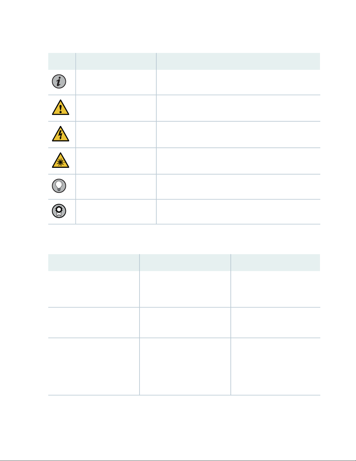
Table 1: Notice Icons
xiii
DescriptionMeaningIcon
Indicates important features or instructions.Informational note
Caution
Indicates a situation that might result in loss of data or hardware
damage.
Alerts you to the risk of personal injury or death.Warning
Alerts you to the risk of personal injury from a laser.Laser warning
Indicates helpful information.Tip
Alerts you to a recommended use or implementation.Best practice
Table 2 on page xiii defines the text and syntax conventions used in this guide.
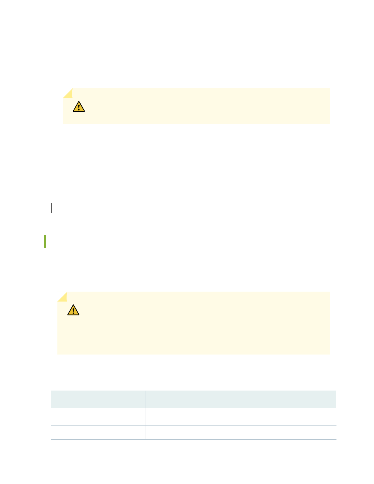
Table 2: Text and Syntax Conventions
ExamplesDescriptionConvention
Fixed-width text like this
Italic text like this
Represents text that you type.Bold text like this
Represents output that appears on
the terminal screen.
Introduces or emphasizes important
•
new terms.
Identifies guide names.
•
Identifies RFC and Internet draft
•
titles.
To enter configuration mode, type
the configure command:
user@host> configure
user@host> show chassis alarms
No alarms currently active
A policy term is a named structure
•
that defines match conditions and
actions.
Junos OS CLI User Guide
•
RFC 1997, BGP Communities
•
Attribute
Page 14

Table 2: Text and Syntax Conventions (continued)
xiv
ExamplesDescriptionConvention
Italic text like this
Text like this
< > (angle brackets)
| (pipe symbol)
Represents variables (options for
which you substitute a value) in
commands or configuration
statements.
Represents names of configuration
statements, commands, files, and
directories; configuration hierarchy
levels; or labels on routing platform
components.
variables.
Indicates a choice between the
mutually exclusive keywords or
variables on either side of the symbol.
The set of choices is often enclosed
in parentheses for clarity.
Configure the machine’s domain
name:
[edit]
root@# set system domain-name
domain-name
To configure a stub area, include
•
the stub statement at the [edit
protocols ospf area area-id]
hierarchy level.
The console port is labeled
•
CONSOLE.
stub <default-metric metric>;Encloses optional keywords or
broadcast | multicast
(string1 | string2 | string3)
# (pound sign)
[ ] (square brackets)
Indention and braces ( { } )
; (semicolon)
GUI Conventions
Indicates a comment specified on the
same line as the configuration
statement to which it applies.
Encloses a variable for which you can
substitute one or more values.
Identifies a level in the configuration
hierarchy.
Identifies a leaf statement at a
configuration hierarchy level.
rsvp { # Required for dynamic MPLS
only
community name members [
community-ids ]
[edit]
routing-options {
static {
route default {
nexthop address;
retain;
}
}
}
Page 15
Table 2: Text and Syntax Conventions (continued)
xv
ExamplesDescriptionConvention
Bold text like this
> (bold right angle bracket)
Represents graphical user interface
(GUI) items you click or select.
Separates levels in a hierarchy of
menu selections.
In the Logical Interfaces box, select
•
All Interfaces.
To cancel the configuration, click
•
Cancel.
In the configuration editor hierarchy,
select Protocols>Ospf.
Documentation Feedback
We encourage you to provide feedback so that we can improve our documentation. You can use either
of the following methods:
Online feedback system—Click TechLibrary Feedback, on the lower right of any page on the Juniper
•
Networks TechLibrary site, and do one of the following:
Click the thumbs-up icon if the information on the page was helpful to you.
•
Click the thumbs-down icon if the information on the page was not helpful to you or if you have
•
suggestions for improvement, and use the pop-up form to provide feedback.
E-mail—Send your comments to techpubs-comments@juniper.net. Include the document or topic name,
•
URL or page number, and software version (if applicable).
Requesting Technical Support
Technical product support is available through the Juniper Networks Technical Assistance Center (JTAC).
If you are a customer with an active Juniper Care or Partner Support Services support contract, or are
Page 16

covered under warranty, and need post-sales technical support, you can access our tools and resources
online or open a case with JTAC.
JTAC policies—For a complete understanding of our JTAC procedures and policies, review the JTAC User
•
Guide located at https://www.juniper.net/us/en/local/pdf/resource-guides/7100059-en.pdf.
Product warranties—For product warranty information, visit https://www.juniper.net/support/warranty/.
•
JTAC hours of operation—The JTAC centers have resources available 24 hours a day, 7 days a week,
•
365 days a year.
Self-Help Online Tools and Resources
For quick and easy problem resolution, Juniper Networks has designed an online self-service portal called
the Customer Support Center (CSC) that provides you with the following features:
Find CSC offerings: https://www.juniper.net/customers/support/
•
Search for known bugs: https://prsearch.juniper.net/
•
xvi
Find product documentation: https://www.juniper.net/documentation/
•
Find solutions and answer questions using our Knowledge Base: https://kb.juniper.net/
•
Download the latest versions of software and review release notes:
•
https://www.juniper.net/customers/csc/software/
Search technical bulletins for relevant hardware and software notifications:
•
https://kb.juniper.net/InfoCenter/
Join and participate in the Juniper Networks Community Forum:
•
https://www.juniper.net/company/communities/
Create a service request online: https://myjuniper.juniper.net
•
To verify service entitlement by product serial number, use our Serial Number Entitlement (SNE) Tool:
https://entitlementsearch.juniper.net/entitlementsearch/
Creating a Service Request with JTAC
You can create a service request with JTAC on the Web or by telephone.
Visit https://myjuniper.juniper.net.
•
Call 1-888-314-JTAC (1-888-314-5822 toll-free in the USA, Canada, and Mexico).
•
For international or direct-dial options in countries without toll-free numbers, see
https://support.juniper.net/support/requesting-support/.
Page 17

1
CHAPTER
Overview
QFX5110 System Overview | 18
QFX5110 Port Panels | 26
QFX5110 Management Panel | 36
QFX5110 Cooling System | 42
QFX5110 Power System | 48
Page 18
QFX5110 System Overview
IN THIS SECTION
QFX5110 Hardware Overview | 18
QFX5110 Hardware Models | 23
Understanding Hardware Redundancy of QFX5110 Components and Functionality | 24
QFX5110 Field-Replaceable Units | 25
QFX5110 Hardware Overview
18
IN THIS SECTION
Benefits of QFX5110 | 18
QFX5110 Models Overview | 19
QFX5110-48S Hardware | 21
QFX5110-32Q Hardware | 22
System Software | 22
The QFX5110 line of switches delivers low latency, flexible deployment options, and rich automation
features. QFX5110 Switches build a strong underlay foundation for flexible, high-performance,
standards-based fabrics and routing that improve network reliability and agility.
This topic covers:
Benefits of QFX5110
Flexible fabric support—QFX5110 offers multiple fabric options to fit your desired network architecture:
Virtual Chassis (VC), with up to 10 members
•
Virtual Chassis Fabric (VC), which offers a single pane management for up to 20 nodes
•
Page 19

MC-LAG, which provides dual-homing with reduced complexity related to STP
•
Junos Fusion Datacenter, where QFX5110 can operate as a satellite leaf node for 1 Gigabit, 10
•
Gigabit, 40 Gigabit, or 100 Gigabit connectivity
Overlay options—QFX5110 provides L2 and L3 VXLAN gateway support that works in conjunction with
a robust EVPN control plane to efficiently manage your virtualized workloads. Another option,
OVSDB-VXLAN can be introduced to stitch virtualized and physical workloads.
High density and low latency applications—Powered with high density 10 Gigabit or 40 Gigabit network
ports and four 100G uplinks, the QFX5110 delivers 1.76 Tbps of throughput and a low latency of 550
nS. Your legacy applications continue to be supported by 100 Mbps or 1 Gigabit copper SFP
transceivers.
QFX5110 Models Overview
The QFX5110 line of switches offers two compact 1 U models that are ideal for top-of-rack, QFX Virtual
Chassis, or Virtual Chassis Fabric (VCF) deployments, the 48-port QFX5110-48S and the 32-port
QFX5110-32Q. Performance of the control plane running on all the QFX5110 switches is enhanced by
the 1.8-Ghz quad-core Intel CPU with 16 GB of memory and 64 GB of solid-state drive (SSD) storage.
Both models offer flexible port configurations of 1-Gigabit Ethernet, 10-Gigabit Ethernet, 40-Gigabit
Ethernet, and 100-Gigabit Ethernet.
19
Both models can be ordered with either ports-to-FRUs or FRUs-to-ports airflow and with AC or DC power
supplies.
The QFX5110-32Q can be used as:
A standalone switch (Junos OS Release 17.2R1 and later).
•
A primary, backup, or line card in a QFX5110 Virtual Chassis (Junos OS Release 17.3R1 and later).
•
A QFX5110 Series Virtual Chassis allows you to connect up to 10 QFX5110 or supported QFX5100
switches into one logical device and manage the device as a single chassis using a ring topology. The
following QFX5100 switches are supported in a QFX5110 Virtual Chassis:
QFX5100-24Q
•
QFX5100-48S
•
QFX5100-96S
•
For a QFX5100 switch to participate in a QFX5110 Virtual Chassis, the switch must have the same
software version and image installed as the software running on the QFX5110 switches in the Virtual
Chassis. You do not need to configure mixed mode. In a QFX5110 Virtual Chassis, we recommend to
use QFX5110 switches in the primary and backup Routing Engine roles, and QFX5100 switches only in
the linecard role.
Page 20

A spine or leaf device in a QFX5110 VCF (Junos OS Release 17.3R1 and later).
•
VCF uses QFX Virtual Chassis technology to interconnect multiple devices into a single logical device
and manage that device as a single logical device inside of a fabric architecture. You can configure up
to a total of 20 QFX5110 or QFX5100 devices in a VCF. Out of the 20 total devices, you can configure
a maximum of 4 spine devices. You can use these models in any combination as leaf devices:
QFX5100-24Q
•
QFX5100-48S
•
QFX5100-48T (Junos OS Release 17.3R2 and later)
•
QFX5100-96S
•
QFX5110-48S
•
NOTE: If only QFX5110-48S switches are available, cable and configure the switches as a
QFX5110 Virtual chassis.
20
NOTE: Unike a QFX5100 VCF, EX4300 switches are not supported in the QFX5110 VCF.
The QFX5110-48S can be used as:
A standalone switch (Junos OS Release 15.1X53-D210 and later).
•
A primary, backup, or line card in a QFX5110 Virtual Chassis (Junos OS Release 17.3R1 and later).
•
A QFX5110 Series Virtual Chassis allows you to connect up to 10 QFX5110 or supported QFX5100
switches into one logical device and manage the device as a single chassis using a ring topology. The
following QFX5100 switches are supported in a QFX5110 Virtual Chassis:
QFX5100-24Q
•
QFX5100-48S
•
QFX5100-96S
•
For a QFX5100 switch to participate in a QFX5110 Virtual Chassis, the switch must have the same
software version and image installed as the software running on the QFX5110 switches in the Virtual
Chassis. You do not need to configure mixed mode. In a QFX5110 Virtual Chassis, we recommend to
use QFX5110 switches in the primary and backup Routing Engine roles, and QFX5100 switches only in
the line card role.
A leaf device in a QFX5110 VCF (Junos OS Release 17.3R1 and later).
•
VCF uses QFX Virtual Chassis technology to interconnect multiple devices into a single logical device
and manage that device as a single logical device inside of a fabric architecture. You can configure up
Page 21

to a total of 20 QFX5110 devices in a QFX5110 VCF. Use QFX5110-32Q as the spine devices. You can
g050472
GM
use these models in any combination as leaf devices:
QFX5100-24Q
•
QFX5100-48S
•
QFX5100-48T (Junos OS Release 17.3R2 and later)
•
QFX5100-96S
•
QFX5110-48S
•
NOTE: If only QFX5110-48S switches are available, cable and configure the switches as a
QFX5110 Virtual chassis.
A satellite device in a Junos Fusion Provider Edge system (Junos OS 18.1R2 and later)
•
21
NOTE: The QFX5110-48S does not support channelized ports in a Junos Fusion environment.
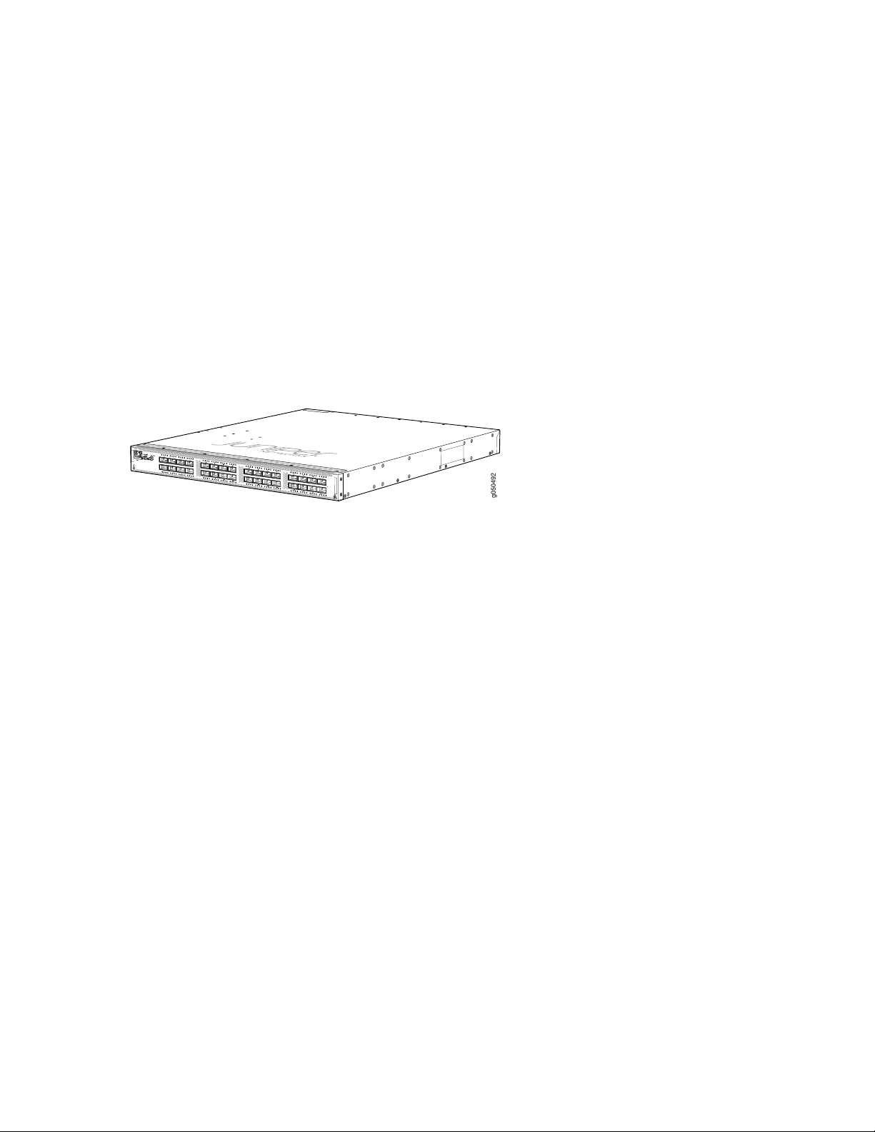
QFX5110-48S Hardware
As shown in Figure 1 on page 21, the QFX5110-48S is a 10-Gigabit Ethernet enhanced small form-factor
pluggable plus (SFP+) switch with 48 SFP+ ports and four 100-Gbps quad small form-factor (QSFP) pluggable
solution (QSFP28) ports. Each SFP+ port (0 through 47)can operate as a native 10-Gigabit Ethernet port
or a 1-Gigabit Ethernet port when 1-Gigabit Ethernet optics are inserted.
Each QSFP28 port (48 through 51) can operate as a native 100-Gigabit Ethernet port, a native 40-Gigabit
Ethernet port, or as 4 independent 10-Gigabit ports when using breakout cables. The four QSFP28 ports
can be used as either access ports or as uplinks. The QFX5110-48S provides an aggregate throughput of
960 Gbps. The QFX5110-48S has a 1 U form factor and comes standard with redundant fans and redundant
power supplies.
Figure 1: QFX5110-48S Port Panel
Page 22
QFX5110-32Q Hardware
g050492
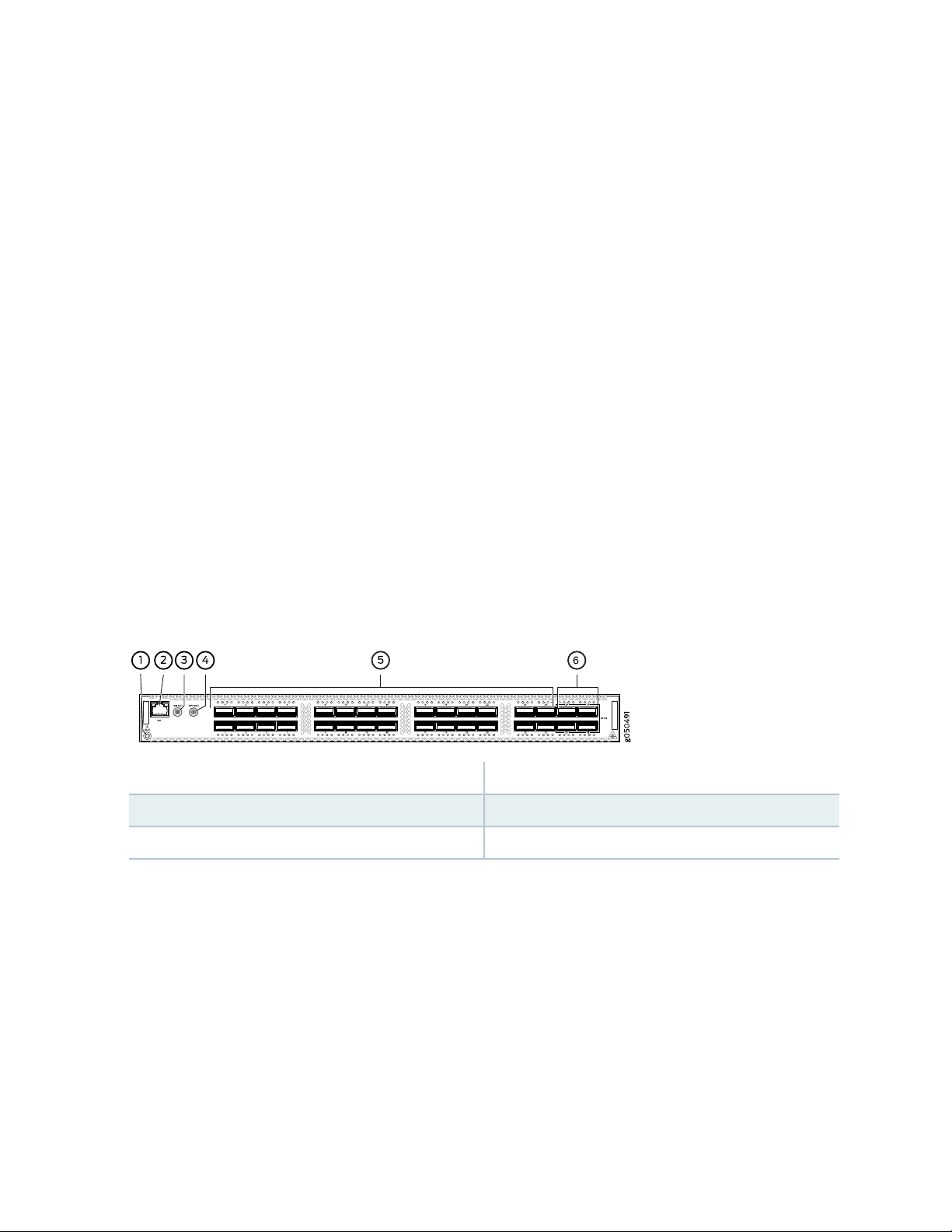
As shown in Figure 2 on page 22, the QFX5110-32Q is a flexible configuration switch allowing either 32
ports of 40-Gigabit Ethernet quad small form-factor pluggable plus (QSFP+) or 20 ports of QSFP+ and 4
ports of high-density 100-Gigabit Ethernet quad small form-factor pluggable solution (QSFP28). Each
QSFP+ port can operate as a native 40-Gigabit Ethernet port, or as four independent 10-Gigabit Ethernet
ports when using breakout cables. The four QSFP28 ports are available either as access ports or as uplinks.
The QFX5110-32Q can be channelized using one of the available system modes. For full details on the
different port channelization modes, see “QFX5110-32Q Port Panel” on page 29. The QFX5110-32Q
switch provides an aggregate throughput of 2.56 Tbps.
Figure 2: QFX5110-32Q Port Panel
22
System Software
QFX Series devices use the Junos operating system (OS), which is installed on a QFX5110 switch’s 64-GB
internal solid-state flash drive. The same Junos OS code base that runs on QFX5110 switches also runs
on all Juniper Networks EX Series switches, and M Series, MX Series, and T Series routers.
The QFX5110-48S switch is supported on Junos OS Release 15.1X53-D210 and later; the QFX5110-32Q
is supported on Junos OS 17.2R1 and later.
Software features are categorized into three tiers: base, premium, and advanced:
Junos OS base features such as Layer 2 and Layer 3 switching, multicast, automation, programmability,
•
Zero Touch Provisioning (ZTP), and basic monitoring are enabled by default from the factory.
Junos OS premium features such as Border Gateway Protocol (BGP), Intermediate System-to-Intermediate
•
System (IS-IS), and Virtual Extensible Local Area Network (VXLAN) require a QFX5K-C1-PFL license on
each QFX5110 switch to use these features.
Junos OS advanced features include Multiprotocol Label Switching (MPLS) in addition to all of the
•
premium features. A QFX5K-C1-AFL license is required on each QFX5110 switch to use these features.
When using QFX5110 switches in a QFX5110 VCF, PFL and AFL licenses are required on the spine device:
leaf devices do not require licensing.
Page 23

QFX5110 switches employ the security feature, Secure Boot, which is based on the UEFI 2.4 standard.
The BIOS has been hardened and serves as a core root of trust. The BIOS updates, the bootloader, and
the kernel are cryptographically protected. No action is required to implement Secure Boot.
If a premium or advanced feature is configured on the QFX5110 without a valid license, an alarm is raised
and system log (syslog) messages are generated.
For more information about which features are supported on QFX Series devices, see Feature Explorer.
You manage the switch using the Junos OS command-line interface (CLI), accessible through the console
and out-of-band management ports on the device.
SEE ALSO
Virtual Chassis Fabric Hardware Documentation
Virtual Chassis Fabric Overview
23
QFX5110 Hardware Models
The QFX5110 switches have 32 or 48 port configurations. Both switches are available with either AC or
DC power supply and with either airflow-in or airflow-out cooling. All models of the QFX5110, except the
QFX5110-32Q_CHAS, ship with two power supplies and five fans installed by default.
Table 3 on page 23 lists the ordering numbers for QFX5110 hardware-only product SKUs.
Table 3: QFX5110 Hardware-only Product Numbers
Power
SupplyPortsProduct Numbers
QFX5110-48S-AFO
4 QSFP28
QFX5110-48S-AFI
4 QSFP28
QFX5110-48S-DC-AFO
Airflow
Air Out (ports-to-FRUs)AC48 SFP+
Air In (FRUs-to-ports)AC48 SFP+
Air Out (ports-to-FRUs)DC48 SFP+
4 QSFP28
Page 24
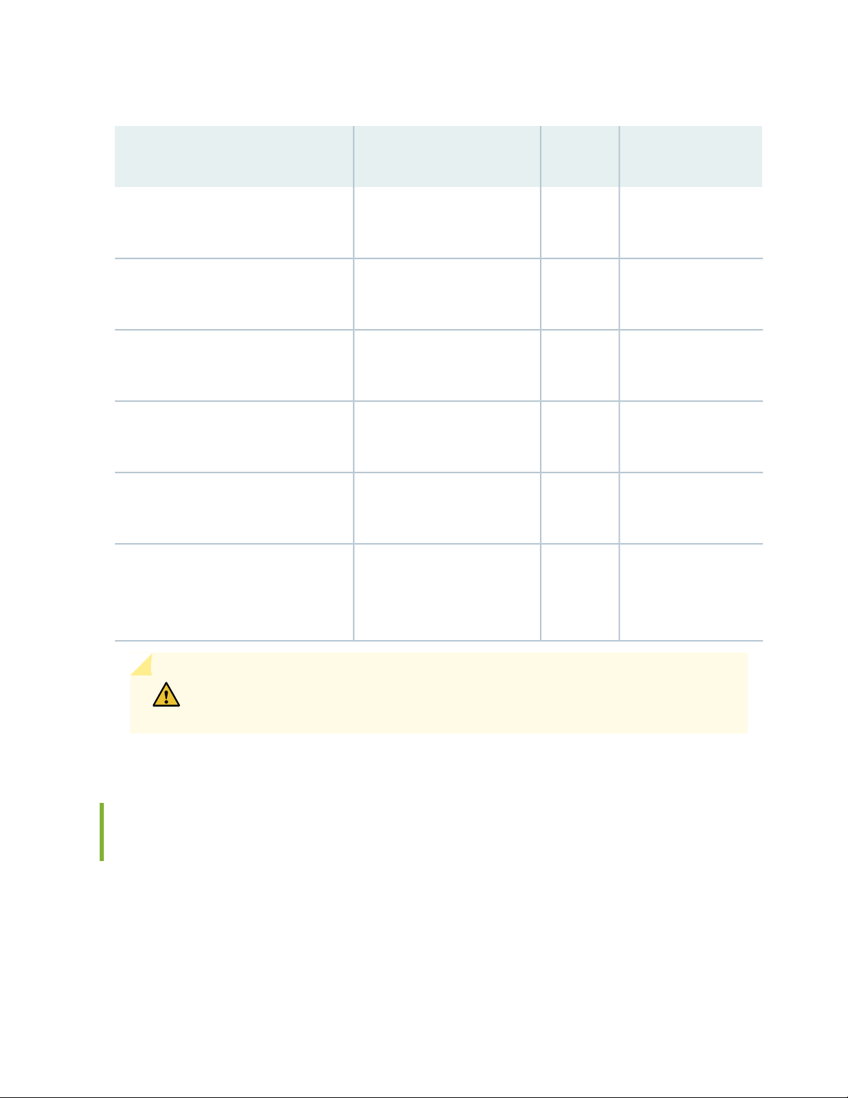
Table 3: QFX5110 Hardware-only Product Numbers (continued)
Power
SupplyPortsProduct Numbers
24
Airflow
QFX5110-48S-DC-AFI
QFX5110-32Q-AFO
QFX5110-32Q-AFI
QFX5110-32Q-DC-AFO
QFX5110-32Q-DC-AFI
QFX5110-32Q-CHAS
4 QSFP28
4 QSFP28
4 QSFP28
4 QSFP28
4 QSFP28
32 QSFP+
4 QSFP28
Order PSUs
separately.
Air In (FRUs-to-ports)DC48 SFP+
Air Out (ports-to-FRUs)AC32 QSFP+
Air In (FRUs-to-ports)AC32 QSFP+
Air Out (ports-to-FRUs)DC32 QSFP+
Air In (FRUs-to-ports)DC32 QSFP+
Fan modules are not
shipped by default.
Order fan modules
separately.
CAUTION: Mixing different types (AC and DC) of power supplies in the same chassis
is not supported. Mixing different airflow modules in the same chassis is not supported.
Understanding Hardware Redundancy of QFX5110 Components and Functionality
The following hardware components provide redundancy on a QFX5110:
Power supplies—The QFX5110 can operate with one power supply. However, all QFX5110 switches,
•
except the QFX5110-32Q-CHAS, ship with two power supplies preinstalled for redundancy.. Each power
supply provides power to all components in the switch. If two power supplies are installed, the two
Page 25
power supplies provide full power redundancy to the device. If one power supply fails or is removed,
the second power supply takes over the electrical load without interruption.
To provide power redundancy to the system, both power supplies must be installed. Connect power
source feed A to one power supply and power source feed B to the second power supply.
CAUTION: Do not connect feed A and feed B to the same power supply input
terminal.
Cooling system—All QFX5110 switches, except the QFX5110-32Q-CHAS, ship with five fan modules
•
installed. If a fan module fails and is unable to keep the QFX5110 within the desired temperature
thresholds, chassis alarms occur and the QFX5110 can shut down.
SEE ALSO
25
QFX5110 Power System | 48
QFX5110 Field-Replaceable Units
Field-replaceable units (FRUs) are components that you can replace at your site. The QFX5110 FRUs are
hot-insertable and hot-removable: you can remove and replace one of them without powering off the
switch or disrupting the switching function.
CAUTION: Replace a failed power supply with a blank panel or new power supply
within one minute of removal to prevent chassis overheating. The switch continues
to operate with only one power supply running. Replace a failed fan module with a
new fan module within one minute of removal to prevent chassis overheating. Do not
operate the switch with missing FRUs for longer than one minute.
Table 4 on page 25 lists the FRUs for the QFX5110 and actions to take before removing them.
Table 4: FRUs in a QFX5110
Required ActionFRU
None.Power supplies
None.Fan modules
Page 26

Table 4: FRUs in a QFX5110 (continued)
Required ActionFRU
26
Optical transceivers
NOTE: If you have a Juniper Care service contract, you can register any addition, change, or
upgrade of hardware components at
https://www.juniper.net/customers/support/tools/updateinstallbase/. Failure to do so can result
in significant delays if you need replacement parts. This note does not apply if you replace existing
components with the same type of component.
SEE ALSO
Maintaining QFX5110 Fan Modules | 123
Maintaining QFX5110 Power Supplies | 126
Removing and Installing Transceivers and Fiber-Optic Cables on QFX5110 | 130
None. We recommend that you disable the interface using the set interfaces
interface-name disable command before you remove the transceiver. See
“Remove a Transceiver” on page 130.
RELATED DOCUMENTATION
QFX5110 Management Panel | 36
QFX5110 Port Panels | 26
QFX5110 Port Panels
IN THIS SECTION
QFX5110-48S Port Panel | 27
QFX5110-32Q Port Panel | 29
QFX5110 Network Port LEDs | 33
Page 27
QFX5110-48S Port Panel
IN THIS SECTION
Switch Overview | 27
Network Ports | 28
Channelizing Interfaces | 29
Virtual Chassis and Virtual Chassis Fabric | 29
The port panel of the QFX5110-48S is primarily comprised of 48 small form-factor pluggable plus (SFP+)
and 4 quad small form-factor pluggable solution (QSFP28) ports. It also provides a central location for the
Precision Time Protocol (PTP) connections to a grandmaster clock.
27
This topic describes:
Switch Overview
The port panel of the QFX5110-48S supports 48 logical 10-GbE ports when operating as a standalone
switch. These data ports (0 through 47) support either 1-Gbps or 10-Gbps SFP+ transceivers. You can also
use SFP+ DAC cables and 10-Gbps active optical cables (AOC) in any access port. Starting in Junos OS
Release 18.3R1, the 10-GbE ports also support 100 Mbps.
The remaining 4 QSFP28 ports (48 through 51) support speeds of 40 GbE or 100 GbE. Each port can be
configured as an independent 100-GbE port or as an independent 40-GbE port. These port are usually
used as uplinks or Virtual Chassis Ports (VCP) on QFX5110 Virtual Chassis or Virtual Chassis Fabric (VCF).
In 40-GbE mode, these ports can be channelized using QSFP+ to SFP+ DAC breakout (DACBO) cables.
The port panel also provides PTP connections to a grandmaster clock (requires Junos OS Release 18.1R1).
There are also 10-MHz pulses-per-second (PPS) SubMiniature B (SMB) input and output connections to
measure the timing drift to and from the grandmaster clock.
Figure 3 on page 28 shows the port panel of the QFX5110-48S.
Page 28
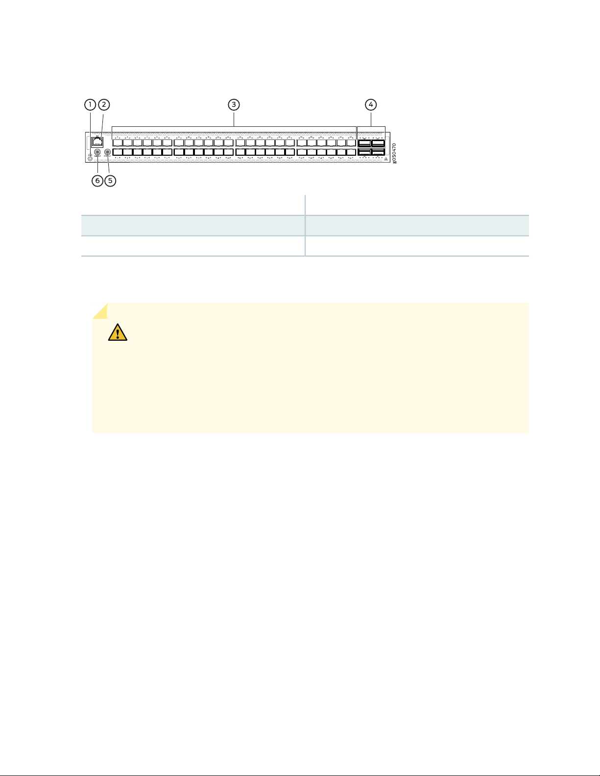
Figure 3: QFX5110-48S Port Panel
Network Ports
28
4—1— 4 QSFP28 portsElectrostatic discharge (ESD) terminal
5—2— Output clock at 10 MhzRJ-45 connection to grandmaster clock
6—3— 1 pulse per second (PPS) output connection48 SFP+ ports
CAUTION: Do not install 1GbE copper transceivers (such as QFX-SFP-1GE-T) directly
above or below another 1GbE copper transceiver. Use only the top row or bottom
row to avoid damage to the device caused by some types of copper transceivers when
the transceivers are installed above or below each other. However, if you are using
copper transceivers with the OEM part number FCLF8521P2BTL-J1 printed on the
transceiver label, you can install the transceivers in any port with no restrictions. For
devices that support 10GbE copper transceivers, there is no similar restriction.
The QFX5110-48S device ports (0 to 47) support:
10-Gbps SFP+ transceivers
•
1-Gbps SFP transceivers
•
SFP+ direct attach copper (DAC) cables
•
SFP+ active optical cables (AOC)
•
The QFX5110-48S uplink ports (48 to 51) support:
100-Gbps QSFP28 transceivers
•
40-Gbps QSFP+ transceivers
•
100-Gbps AOC
•
40-Gbps AOC (Junos OS 18.3R1 and later)
•
100-Gbps QSFP28 DAC cables
•
40-Gbps QSFP+ DAC cables
•
Page 29

40-Gbps QSFP+ to SFP+ DACBO cables (40-Gbps breaks out to 10-Gbps for copper connections)
•
40-Gbps AOCBO cables (40-Gbps breaks out to 10-Gbps for fiber connections)
•
Channelizing Interfaces
For downstream traffic, the QFX5110-48S has 4 physical or 16 logical ports that can be used for port
channelization. The default 100-Gigabit Ethernet ports can be configured as 40-Gigabit Ethernet, and in
this configuration can either operate as dedicated 40-Gigabit Ethernet ports or can be channelized to 4
independent 10-Gigabit Ethernet ports using copper or fiber breakout cables.
To channelize the ports, manually configure the port speed using the set chassis fpc slot-number port
port-number channel-speed speed command, where the speed can be set to 10-Gigabit Ethernet, 40-Gigabit
Ethernet, or 100-Gigabit Ethernet. The ports do not support auto-channelization.
Virtual Chassis and Virtual Chassis Fabric
29
To connect QFX5110 switches as members in a QFX5110 Virtual Chassis, you need a pair of dedicated
ports on each switch and cables that link each member in the Virtual Chassis into a ring topology. Each
member in the ring has at least one direct Virtual Chassis port (VCP) connection to a upstream and
downstream member. QFX5110 switches are recommended in the primary, backup, or line card role. You
may only mix QFX5100 members with QFX5110 members in a QFX5110 Virtual Chassis; no other QFX
Series or EX Series switches are supported. See “Connecting QFX5110 and QFX5100 Members in a
QFX5110 Virtual Chassis” on page 116 for a a diagram of cabling QFX5110 switches in a ring topology.
To connect a QFX5110 switch as a spine or leaf device in a Virtual Chassis Fabric (VCF), you need a pair
of dedicated ports and cables that link each spine device and leaf device in the VCF. All spine devices have
at least one direct VCP connection to each leaf device in the VCF. See “Connecting QFX5110 in a QFX5110
Virtual Chassis Fabric” on page 117 for a cabling diagram.
QFX5110-32Q Port Panel
IN THIS SECTION
Switch Overview | 30
Network Ports | 30
Channelizing Interfaces | 31
Virtual Chassis and Virtual Chassis Fabric | 32
Page 30
The port panel of the QFX5110-32Q primarily comprises 28 quad small form-factor pluggable plus (QSFP+)
6
ports and 4 quad small form-factor pluggable solution (QSFP28) ports. The mixture of QSFP+ and QSFP28
ports allows for flexible configuration as either all 40-Gigabit Ethernet ports or a mixture of 40-Gigabit
Ethernet and 100-Gigabit Ethernet for high-speed uplinks. The port panel also provides a central location
for the Precision Time Protocol (PTP) connections to a grandmaster clock.
This topic describes:
Switch Overview
The ports on the QFX5110-32Q support 40-Gbps or 100-Gbps speeds natively. All ports autosense the
type of transceiver and set the port to the corresponding speed. The QSFP+ ports can support channelization
to four independent 10 GbE downstream ports, see “Channelizing Interfaces” on page 31. Although all
network ports can be configured as either uplink or as access ports, best practice is to configure the four
QSFP28 ports (28 through 31) as uplinks to take advantage of the 100-Gbps speeds.
The port panel also provides PTP connections to a grandmaster clock (requires Junos OS Release 18.1R1).
There are also 10-MHz pulses-per-second (PPS) SubMiniature B (SMB) input and output connections to
measure the timing drift to and from the grandmaster clock.
30
Figure 4 on page 30 shows the port panel of the QFX5110-32Q.
Figure 4: QFX5110-32Q Port Panel
4—1— 1 pulse per second (PPS) output connectionElectrostatic discharge (ESD) terminal
5—2— 28 QSFP+ portsRJ-45 connection to grandmaster clock
6—3— 4 QSFP28 portsOutput clock at 10 MHz
Network Ports
The QFX5110-32Q device ports (0 through 27) support:
40-Gbps QSFP+ transceivers
•
QSFP+ direct attach copper (DAC) cables
•
QSFP+ active optical cables (AOC) (Junos OS Release 18.3R1 and later)
•
Page 31

40-Gbps QSFP+ to SFP+ DACBO cables (40 Gbps breaks out to 10 Gbps for copper connections on
•
supported ports)
40-Gbps AOCBO cables (40 Gbps breaks out to 10 Gbps for fiber connections on supported ports)
•
The QFX5110-32Q uplink ports (28 through 31) support:
100-Gbps QSFP28 transceivers
•
40-Gbps QSFP+ transceivers
•
100-Gbps AOC
•
40-Gbps AOC (Junos OS Release 18.3R1 or later)
•
100-Gbps QSFP28 DAC cables
•
40-Gbps QSFP+ DAC cables
•
Channelizing Interfaces
31
CAUTION: Starting with Junos OS Release 18.1R1, default behaviors changed for:
System mode—Flexi-pic mode is replaced by non-oversubscribed mode.
•
Auto-sense—The ports auto-sense the transceiver and set the port speed to match.
•
The Packet Forwarding Engine on the switch is restarted when you issue system mode
changes. As a result, you might experience packet loss on the switch.
The following system modes are available on the QFX5110-32Q:
Default mode (from Junos OS Release 17.2R1 up to Junos OS Release 18.1R1)
•
All 32 QSFP+ and QSFP28 ports on the switch are configured for 40-Gigabit Ethernet only. All ports
are supported as access or uplink ports, but cannot be channelized.
Default mode (Junos OS 18.1R1 and later)
•
If you connect 40-Gbps optics to all 32 ports, only ports 1 through 18 are available to channelize to 4
independent 10-Gbps speed downstream ports. You can use the remaining ports as dedicated 40 Gbps
ports. No ports are disabled.
Depending on the optics installed, you can channelize between 18 to 20 ports.
If the system detects a 100-Gbps optic in any one of the QSFP28 ports (28 to 31), the port forms a
•
port group and disables ports 20 to 27. The 40 Gbps QSFP+ ports 0 to 19 can be channelized to 4
independent 10 Gbps speed downstream ports.
Page 32

If the system detects 40 Gbps optics in the QSFP28 ports (28 to 31), you can channelize the 40 Gbps
•
QSFP+ ports 1 to 18 to 4 independent 10 Gbps speed downstream ports. You can use the remaining
ports as dedicated 40 Gbps ports. No ports are disabled.
CAUTION: Ports 20 through 27 are not be available for channelization if you have
populated the 100 Gbps QSFP28 ports with 100 Gbps optics.
Flexi-pic mode (from Junos OS Release 17.2R1 up to Junos OS Release 18.1R1):
•
Ports 0 through 19 of the switch are configured for 40-Gigabit Ethernet and can be channelized to 4
•
independent 10-Gigabit Ethernet ports.
Ports 20 though 27 are disabled.
•
Ports 28 through 31 are configured as 100-Gigabit Ethernet.
•
CAUTION: Take care when changing the channelization mode from Flexi-pic to
default. If you have existing ports that are channelized in Flexi-pic mode, remove
the channelization from the interface before changing the system mode. Changing
the Flexi-pic mode to the default mode with channelized ports causes the ports to
go down, log a system log error, and remain down. You must manually remove the
channelization configuration on the ports to bring the ports up in default mode.
Because there can be a slight loss of data while the FPC reboots, we recommend
that you only configure the changes during a maintenance window for this release.
32
NOTE: QFX5110-32Q switches that are configured for Flexi-pic mode and upgraded to Junos
OS Release 18.1R1 and later come up in default mode.
Non-oversubscribed mode (Junos OS Release 18.1R1 and later)
•
Ports 0 through 23 only can be channelized. The remaining ports are disabled. Use this mode to achieve
960 Gbps speeds for either 24 ports of 40 Gigabit Ethernet or 96 ports of 10 Gigabit Ethernet.
Use the request chassis system-mode command to change the system mode for the switch. If you attempt
to channelize a non-supported port, the configuration is ignored.
Virtual Chassis and Virtual Chassis Fabric
To connect QFX5110 switches as members in a QFX5110 Virtual Chassis, you need a pair of dedicated
ports on each switch and cables that link each member in the Virtual Chassis into a ring topology. Each
member in the ring has at least one direct Virtual Chassis port (VCP) connection to a upstream and
Page 33

downstream member. QFX5110 switches are recommended in the master, backup, or line card role. You
g050236
Bi-colored LEDs
may only mix QFX5100 members with QFX5110 members in a QFX5110 Virtual Chassis; no other QFX
Series or EX Series switches are supported. See “Connecting QFX5110 and QFX5100 Members in a
QFX5110 Virtual Chassis” on page 116 for a a diagram of cabling QFX5110 switches in a ring topology.
To connect a QFX5110 switch as a spine or leaf device in a Virtual Chassis Fabric (VCF), you need a pair
of dedicated ports and cables that link each spine device and leaf device in the VCF. All spine devices have
at least one direct VCP connection to each leaf device in the VCF. See “Connecting QFX5110 in a QFX5110
Virtual Chassis Fabric” on page 117 for a cabling diagram.
QFX5110 Network Port LEDs
The Link/Activity LED configuration for QFX5110-48S uses bi-colored LEDs. The link LED indicates link
activity or a fault. See Table 5 on page 33.
Table 5: QFX5110-48S Access Port and Uplink LED Locations
33
LocationIndicatorsPort TypeModel
QSFP28QFX5110-48S
SFP+
Link and
Activity
Status
See
Table6onpage34.
Link and
Activity
Status
See
Table7onpage34,
As shown in Table 5 on page 33 and Table 8 on page 35 there are four bi-color LEDs for each QSFP+
access port. The first LED indicates link presence and activity, while the remaining LEDs indicate status.
Table 6 on page 34 describes how to interpret the Link/Activity QSFP28 port LEDs, counting from the
left-most position.
Page 34

Table 6: Network Port LEDs on QSFP28 Ports on a QFX5110
DescriptionStateColorPosition
34
OffUnlit1–4
On steadilyGreen1
Blinking
On steadilyGreen2-4
Blinking
BlinkingAmberAll
The port is administratively disabled, there is no power, the link
is down, or there is a fault.
A link is established (either 100-Gigabit or 40-Gigabit,
non-channelized) but there is no link activity. When this LED is
on, the LEDs in positions 2 to 4 are off.
A link is established (either 100-Gigabit or 40-Gigabit,
non-channelized) and there is link activity.
A 40-Gigabit link is established in channelized mode, but there
is no link activity.
A 40-Gigabit link is established in channelized mode, and there
is link activity.
All four LEDs blink to indicate the beacon function was enabled
on the port.
Table 7 on page 34 describes how to interpret the Link/Activity LEDs on SFP+ ports.
Table 7: Network Port LEDs on SFP+ Ports on a QFX5110-48S Switch
DescriptionStateColorLED
OffUnlitLink/Activity
The port is administratively disabled, there is no power, the link
is down, or there is a fault.
A link is established, but there is no link activity.On steadilyGreen
A link is established, and there is link activity.Blinking
The beacon is enabled on the port.BlinkingAmber
Page 35

Table 7: Network Port LEDs on SFP+ Ports on a QFX5110-48S Switch (continued)
g050236
Bi-colored LEDs
DescriptionStateColorLED
The link is down or there is a fault.OffUnlitStatus
35
On steadilyGreen
BlinkingGreen
A 10-Gigabit Ethernet transceiver is installed in the port and link
is established.
A 1-Gigabit Ethernet transceiver is installed in the port and the
link is established.
The beacon function is enabled on the port.Slow blippingAmber
Table 8: QFX5110-32Q Access Port and Uplink LED Locations
QFX5110-32Q
QSFP28 and
QSFP+
Link and
Activity
Status
SEE ALSO
QFX5110 Management Panel | 36
Install a Transceiver | 134
Connect a Fiber-Optic Cable | 137
RELATED DOCUMENTATION
QFX5110 Field-Replaceable Units | 25
Channelizing Interfaces on QFX3500, QFX3600, QFX5100, QFX10002, QFX10008, QFX10016, and
EX4600 Switches
Connecting the QFX5110 in a Virtual Chassis or Virtual Chassis Fabric | 116
Page 36

QFX5110 Management Panel
IN THIS SECTION
QFX5110 Management Panel Description | 36
QFX5110 Management Port LEDs | 38
QFX5110 Chassis Status LEDs | 39
QFX5110 Management Panel Description
The management panel of the QFX5110 is found on the field-replaceable unit (FRU) end of the switch, as
shown in Figure 5 on page 36. See Figure 6 on page 37 for FRUs and management panel detail.
36
Figure 5: QFX5110 Switch, FRU End
2—Fan modules
3—1— Power supply unitsManagement panel
Page 37

Figure 6: Management Panel Components on QFX5110
4—1— USB portStatus LEDs
37
em0–RJ-45 (1000BASE-T) management Ethernet
port (C0)
and an additional SFP management Ethernet port
(second C0)
3—RJ-45 console port (CON)
5—2— em1–SFP management Ethernet port (C1)
Cage (socket for either 1-GbE copper SFP or fiber
SFP)
The management panel consists of the following components:
Status LEDs, see “QFX5110 Chassis Status LEDs” on page 39.
•
Switch product number
•
Management ports C0 and C1, see “QFX5110 Management Port LEDs” on page 38.
•
C0–Use the RJ-45 connectors for 10/100/1000BASE-T or to cable a virtual management Ethernet
•
(VME) interface for spine members in a VCF. See “Connect a Device to a Network for Out-of-Band
Management” on page 102.
NOTE: If both C0 ports are cabled, the copper C0 has priority over the fiber C0.
C1–Use the SFP connector for 1000BASE-X.
•
USB port for image updates
•
Console port (RJ-45) to support RS-232 serial ports. The LEDs above the port indicate status and link.
•
Page 38

QFX5110 Management Port LEDs
The management ports (labeled C0 for 10/100/1000BASE-T and C1 for 10/100/1000BASE-T and SFP
1000BASE-X connections) on a QFX5110 switch have two LEDs that indicate link status and link activity
(see Figure 7 on page 38). The left LED indicates status; the right LED indicates link/activity.
Figure 7: Management Port LEDs on a QFX5110
38
4—1— USB portStatus LEDs
em0–RJ-45 (10/100/1000BASE-T) management
Ethernet port (C0)
3—RJ-45 console port (CON))
5—2— em1–SFP management Ethernet port (C1)
Table 9 on page 38 describes the management port LEDs.
Table 9: Management Port LEDs on a QFX5110
OffUnlitLink/Activity
cage (socket for either 10/100/1000BASE-T RJ-45
SFP or 1-GbE fiber SFP)
DescriptionStateColorLED
No link is established, there is a fault, or the link is
down.
A link is established, but there is no link activity.On steadilyGreen
A link is established, and there is link activity.Blinking or flickering
Either the port speed is 10 M or the link is down.OffUnlitStatus
The port speed is 1000 M.On steadilyGreen
The port speed is 100 M.On steadilyAmber
Page 39

QFX5110 Chassis Status LEDs
The QFX5110 switch series has four status LEDs on the FRU side of the chassis, next to the management
ports (see Figure 8 on page 39).
Figure 8: Chassis Status LEDs on a QFX5110 Switch
39
4—1— USB portStatus LEDs
em0–RJ-45 (10/100/1000 BASE-T) management
Ethernet port (C0)
3—RJ-45 console port (CON)
5—2— em1–SFP management Ethernet port (C1)
cage (socket for either 10/100/1000 BASE-T RJ-45
SFP or 1-GbE fiber SFP)
Table 10 on page 40 describes the chassis status LEDs on a QFX5110, their colors and states, and the
status they indicate. You can view the colors of the three LEDs remotely through the CLI by issuing the
operational mode command show chassis lcd.
Page 40

Table 10: Chassis Status LEDs on a QFX5110 Switch
40
DescriptionStateColorName
OffUnlitALM–Alarm or beacon
On steadilyRed
On steadilyAmber
The switch is halted or there is no
alarm.
A major hardware fault has occurred,
such as a temperature alarm or power
failure, and the switch has halted.
Power off the QFX5110 by setting the
AC power source outlet to the off (O)
position, or unplugging the AC power
cords. Correct any voltage or site
temperature issues, and allow the
switch to cool down. Power on the
QFX5110 and monitor the power
supply and fan LEDs to help determine
where the error is occurring.
A minor, non-critical alarm has
occurred, such as a software error.
Power off the QFX5110 by setting the
AC power source outlet to the off (O)
position, or unplugging the AC power
cords. Power on the QFX5110 and
monitor the status LEDs to ensure that
Junos OS boots properly.
The switch is powered off or halted.OffUnlitSYS–System
On steadilyGreen
BlinkingGreen
Junos OS for QFX Series is loaded on
the switch.
The switch is participating as:
A member in a QFX Virtual Chassis
•
A leaf device in a Virtual Chassis
•
Fabric (VCF)
A spine device in a VCF
•
A Routing Engine Primary in a VCF
•
A Routing Engine Backup in a VCF
•
Page 41

Table 10: Chassis Status LEDs on a QFX5110 Switch (continued)
41
DescriptionStateColorName
Virtual Chassis or Routing
Engine Primary in a VCF
OffUnlitMST–Primary in a QFX
On steadilyGreen
BlinkingGreen
OffUnlitID–Identification
BlinkingBlue
The switch is a line card member in a
QFX Virtual Chassis.
The switch is one of the following:
A standalone switch
•
In the primary role in a QFX Virtual
•
Chassis
Is the routing engine primary in a
•
VCF
The switch is the backup primary in a
QFX Virtual Chassis or the backup
routing engine in a VCF.
The beacon feature is not enabled on
the switch. This feature is enabled
using the request chassis beacon
command.
The beacon feature is enabled on the
switch. This feature is enabled using
the request chassis beacon command.
SEE ALSO
show chassis alarms
request chassis beacon
RELATED DOCUMENTATION
QFX5110 Field-Replaceable Units | 25
USB Port Specifications for the QFX Series | 92
Page 42

QFX5110 Cooling System
IN THIS SECTION
QFX5110 Cooling System and Airflow Description | 42
QFX5110 Fan Module LED | 47
QFX5110 Cooling System and Airflow Description
IN THIS SECTION
42
Fan Modules | 42
Do Not Install Components with Different Airflow or Wattage in the Switch | 46
The cooling system in an QFX5110 device consists of five fan modules and a single fan in each power
supply. The switch can be set up to work in one of two airflow directions:
Airflow In–Air comes into the switch through the vents in the field-replaceable units (FRUs)
•
Airflow Out–Air comes into the switch through the vents in the port panel.
•
All QFX5110 switches, except the QFX5110-32Q-CHAS, are shipped with five fan modules and two power
supplies. Order fans for the QFX5110-32Q-CHAS separately.
CAUTION: Airflow In and Airflow Out fans and power supplies cannot be mixed in
the same chassis.
This topic describes:
Fan Modules
The fan modules in QFX5110 devices are hot-insertable and hot-removable FRUs. These fan modules are
designed for one of the two available airflow directions (Airflow In or Airflow Out). The fan modules are
Page 43

also color-coded for the airflow direction. The fan modules are installed in the fan module slots between
the management panel and the power supplies.
The QFX5110 fan modules have five fan modules numbered 0 through 4 counting from left to right. Each
fan module slot has a fan icon next to it.
Figure 9 on page 43 shows the fan module.
Figure 9: QFX5110 Fan Module
43
You remove and replace a fan module from the FRU end of the chassis. The switch continues to operate
for a limited period of time (30 seconds) during the replacement of the fan module without thermal
shutdown.
NOTE: All fan modules must be installed for optimal operation of the switch.
The fan modules are available in two product SKUs that have different airflow directions, airflow in and
airflow out. Airflow in is indicated on the module by the azure blue color and a label marked AIR IN. Airflow
in this version of the fan module bring air into the fans and power supplies and exhaust air through the
ports. Likewise, airflow out is indicated by a gold color and a label marked AIR OUT. Airflow out versions
of the fan module brings air into the switch through the vents around the ports and exhaust air through
the fans and power supplies. Table 11 on page 44 lists the available fan module product SKUs and the
direction of airflow in them.
Page 44

Table 11: Fan Modules in the QFX5110
Airflow
DiagramFan Module
Label on the
Fan Module
Color of
Fan
Module
Direction of Airflow
in the Fan Module
44
Power
Supplies
AIR INFigure10 on page 45QFX5110-48S-FANAFI
AIR INFigure 12 onpage 46QFX5110-32Q-FANAFI
Juniper
Azure Blue
Juniper GoldAIR OUTFigure11on page 45QFX5110-48S-FANAFO
Juniper
Azure Blue
FRU-to-port, that is, air
comes in from the end
of the switch with the
fans; air exhausts from
the switch end with
ports (also known as
back-to-front airflow).
Port-to-FRU, that is, air
comes in through vents
on the end with ports;
air exhausts out the end
with the fans (also
known as front-to-back
airflow).
FRU-to-port, that is, air
comes in from the end
of the switch with the
fans; air exhausts from
the switch end with
ports (also known as
back-to-front airflow).
You must install
only power
supplies that
have AIR IN
labels in
switches in
which the fan
modules have
AIR IN labels.
You must install
only power
supplies that
have AIR OUT
labels in
switches in
which the fan
modules have
AIR OUT labels.
You must install
only power
supplies that
have AIR IN
labels in
switches in
which the fan
modules have
AIR IN labels.
Juniper GoldAIR OUTFigure13 on page46QFX5110-32Q-FANAFO
Port-to-FRU, that is, air
comes in through vents
on the end with ports;
air exhausts out the end
with the fans (also
known as front-to-back
airflow).
You must install
only power
supplies that
have AIR OUT
labels in
switches in
which the fan
modules have
AIR OUT labels.
Page 45

In data center deployments, position the switch in such a manner that the AIR IN labels on switch
components are next to the cold aisle, and AIR OUT labels on switch components are next to the hot
aisle. See Figure 10 on page 45 through Figure 13 on page 46.
Figure 10: Air In Airflow Through the QFX5110-48S
45
Figure 11: Air Out Airflow Through the QFX5110-48S
Page 46

Figure 12: Air In Airflow Through the QFX5110-32Q
46
Figure 13: Air Out Airflow Through the QFX5110-32Q
Do Not Install Components with Different Airflow or Wattage in the Switch
Do not mix power supplies with different airflow. If the power supplies are color-coded, ensure they are
either all azure blue for airflow in models or all gold for airflow out models. If the power supplies are not
color-coded but have a label, ensure that the chassis is either using all airflow in (AFI ) or all airflow out
(AFO). Likewise, ensure that all fan modules have the same airflow and match the airflow of the power
Page 47

supplies. Fan modules are also either color-coded azure blue for airflow in or gold for airflow out. If the
g050487
CO
CON
ALM
SYS
MST
ID
RESET
CO
1
fan module has a label instead of being color-coded, ensure that labels (AIR IN and AIR OUT) are not
mixed. If the fan modules have AIR IN labels, the power supplies must also have AIR IN labels; if the fan
modules have AIR OUT labels, the power supplies must also have AIR OUT labels.
Mixing components with different airflows in the same chassis hampers the performance of the cooling
system of the switch and leads to overheating of the chassis.
CAUTION: The system raises an alarm if a fan module fails or if the ambient
temperature inside the chassis rises above the acceptable range. If the temperature
inside the chassis rises above the threshold temperature, the system shuts down
automatically.
Do not mix fan modules with different wattage. Only use the replacement fan modules that are designed
for use with your product number. See Table 11 on page 44 for the correct part number for your QFX5110.
47
CAUTION: Do not mix AC and DC power supplies in the same chassis.
However, if you need to convert a QFX5110 to have a different airflow, you can change the airflow pattern.
To convert an AIR IN product SKU to an AIR OUT product SKU or an AIR OUT product SKU to a AIR IN
product SKU, you must replace all of the fans and power supplies at one time to use the new direction.
The system raises an alarm when the system is converted, which is normal.
QFX5110 Fan Module LED
Figure 14 on page 47 shows the location of the LED next to the fan module.
Figure 14: Fan Module LED in a QFX5110 Switch
1—Fan LED
Table 12 on page 48 describes the function of the fan tray LED.
Page 48

Table 12: Fan Tray LED in a QFX5110 Switch
48
DescriptionStateColorName
On steadilyGreenFan
BlinkingAmber
The fan module is operating normally. The system
has verified that the module is engaged, that the
airflow is in the correct direction, and that the
fan is operating correctly.
An error has been detected in the fan module.
Replace the fan module as soon as possible.
Either the fan has failed or it is seated incorrectly.
To maintain proper airflow through the chassis,
leave the fan module installed in the chassis until
you are ready to replace it.
Under normal operating conditions, the fan modules operate at a moderate speed. Temperature sensors
in the chassis monitor the temperature within the chassis.
The system raises an alarm if a fan module fails or if the ambient temperature inside the chassis rises above
the acceptable range. If the temperature inside the chassis rises above the threshold temperature, the
system shuts down automatically.
RELATED DOCUMENTATION
QFX5110 System Overview | 18
Prevention of Electrostatic Discharge Damage | 196
Maintaining QFX5110 Fan Modules | 123
QFX5110 Power System
IN THIS SECTION
QFX5110 AC Power Supply Description | 49
QFX5110 AC Power Specifications | 50
QFX5110 AC Power Cord Specifications | 51
QFX5110 AC Power Supply LEDs | 53
QFX5110 DC Power Supply Description | 54
Page 49

QFX5110 DC Power Specifications | 56
g050255
1 2
3
4
QFX5110 DC Power Supply LEDs | 56
QFX5110 AC Power Supply Description
Except for the QFX5110-32Q-CHAS, the QFX5110 switches are shipped from the factory with two 650 W
power supplies pre-installed. See Figure 15 on page 49 for an example of a QFX5110 AC power supply.
Each power supply is a hot-removable and hot-insertable field-replaceable unit (FRU) when the second
power supply is installed and running. You can install replacement power supplies in the two slots next to
the fan modules without powering off the switch or disrupting the switching function.
The AC power supply in QFX5110 switches is available in different airflow configurations. Be sure to use
the correct power supply for your chassis product SKU (see Table 13 on page 50).
49
CAUTION: Do not mix power supplies with different airflow. The system raises an
alarm when a power supply having a different airflow or wattage is inserted into the
chassis.
Figure 15: AC Power Supply in QFX5110 Switches
3—1— AC appliance inletHandle
4—2— Security latchPower cord retainer
The power supply provides FRU-to-port or port-to-FRU airflow depending on the product SKU you
purchase. On legacy switches, or switches with an LCD, this airflow is called back-to-front and front-to-back.
The power supplies either have labels on the handles that indicate the direction of airflow or they have
color-coded handles with a fan icon. See Figure 16 on page 50 for an example of the power supply. Either
Page 50

a power supply has the label AFI or a blue handle, which denotes FRU-to-port airflow. A power supply
with the label AFO or a gold-colored handle denotes port-to-FRU airflow.
Figure 16: Power Supply Handle Detail
1—Fan icon on handle
CAUTION: Verify that the airflow direction on the power supply handle matches the
direction of airflow in the chassis. Ensure that each power supply you install in the
chassis has the same airflow direction. If you install power supplies with two different
airflow directions, Junos OS raises an alarm. If you need to convert the airflow pattern
on a chassis, you must change out all the fans and power supplies at one time to use
the new direction.
50
Table 13 on page 50 shows the different power supplies and their direction of airflow.
Table 13: Airflow Direction in QFX5110 AC Power Supplies
Color of Power Supply HandleDirection of AirflowProduct Number
Juniper Azure BlueFRU-to-portJPSU-650W-AC-AFI
Juniper GoldPort-to-FRUJPSU-650W-AC-AFO
To avoid electrical injury, carefully follow instructions in “Connecting AC Power to a QFX5110” on page 108.
QFX5110 AC Power Specifications
Table 14 on page 51 describes the AC power specifications for QFX5110 switches. The typical and
maximum power consumption values are calculated using small form-factor plus (SFP+) direct attach copper
Page 51

(DAC) cables on all network ports and all 100GBASE-SR4 transceivers in the uplink ports. Traffic is run at
25° C ambient.
Table 14: AC Power Specifications for QFX5110 Models
QFX5110-32Q SpecificationQFX5110-48S SpecificationItem
Operating range: 90 VAC to 264 VACOperating range: 90 VAC to 264 VACAC input voltage
50–60 Hz50–60 HzAC input line
frequency
3.6 A at 90 VAC3.6 A at 90 VACAC input current
rating
250 W150 WIdle power
consumption
290 W195 W (input current of 0.973 A at 220 VAC)Typical power
consumption
51
340 W300 WMaximum power
consumption
QFX5110 AC Power Cord Specifications
Detachable AC power cords are shipped with the chassis, if you include them as part of your order. The
coupler is type C13 as described by International Electrotechnical Commission (IEC) standard 60320. The
plug end of the power cord fits into the power source outlet that is standard for your geographical location.
NOTE: In North America, AC power cords must not exceed 14.75 feet (approximately 4.5 meters)
in length, to comply with National Electrical Code (NEC) Sections 400-8 (NFPA 75, 5-2.2) and
210-52, and Canadian Electrical Code (CEC) Section 4-010(3). The cords that can be ordered
for the QFX Series switches are in compliance.
Table 15 on page 52 lists AC power cord specifications provided for each country or region.
Page 52

Table 15: AC Power Cord Specifications
g021274
52
Australia
China
Europe (except
Italy, Switzerland,
and United
Kingdom)
Italy
Japan
North America
Electrical
SpecificationsCountry/Region
50 Hz
250 VAC, 10 A,
50 Hz
50 Hz
50 Hz
50 Hz or 60 Hz
60 Hz
Plug
Standards
2099.1–2008
Juniper Model
Number
Spare Juniper Model
Number
CBL-EX-PWR-C13-AUCG_CBL-C13-06-AUIEC 60884-1250 VAC, 10 A,
CBL-EX-PWR-C13-CHCG_CBL-C13-06-CHGB
CBL-EX-PWR-C13-EUCG_CBL-C13-06-EUIEC 60884-1250 VAC, 10 A,
CBL-EX-PWR-C13-ITCG_CBL-C13-06-ITCEI.23-16/VII250 VAC, 10 A,
CBL-EX-PWR-C13-JPCG_CBL-C13-06-JPJIS C8303125 VAC, 12 A,
CBL-EX-PWR-C13-USCG_CBL-C13-06-USNEMA 5-ISP125 VAC, 13 A,
Graphic
South Korea
60 Hz
Switzerland
United Kingdom
250 VAC, 10 A,
50 Hz
50 Hz
1011–2009
SEE ALSO
QFX5110 AC Power Supply Description | 49
General Safety Guidelines and Warnings | 162
General Electrical Safety Guidelines and Warnings | 194
Prevention of Electrostatic Discharge Damage | 196
AC Power Supply for a QFX5100 Device
QFX10002 AC Power Specifications
CBL-EX-PWR-C13-KRCG_CBL-C13-06-KRKSC 8305250 VAC, 10 A,
CBL-EX-PWR-C13-SZCG_CBL-C13-06-SZSEV
CBL-EX-PWR-C13-UKCG_CBL-C13-06--UKBS 1363250 VAC, 10 A,
Page 53

QFX5200 AC Power Specifications
g050008
AC OK
DC OK
Fault
QFX5110 AC Power Specifications | 50
QFX5110 AC Power Supply LEDs
Figure 17 on page 53 shows the location of the LEDs on the power supply.
Figure 17: AC Power Supply LEDs on a QFX5110 Switch
53
Table 16 on page 53 describes the LEDs on the AC power supplies.
Table 16: AC Power Supply LEDs on a QFX5110 Switch
DescriptionStateColorLED
OffUnlitAC OK
OffUnlitDC OK
On steadilyAmberFault
The power supply is disconnected from power, or power is not
coming into the power supply.
Power is coming into the power supply.On steadilyGreen
The power supply is disconnected from power, or the power supply
is not sending out power correctly.
The power supply is sending out power correctly.On steadilyGreen
An error has been detected in the power supply. Replace the power
supply as soon as possible. To maintain proper airflow through the
chassis, leave the power supply installed in the chassis until you
are ready to replace it.
Page 54

NOTE: If the AC OK LED and the DC OK LED are unlit, either the AC power cord is not installed
properly or the power supply fuse has failed. If the AC OK LED is lit and the DC OK LED is unlit,
the AC power supply is installed properly, but the power supply has an internal failure.
QFX5110 DC Power Supply Description
Except for the QFX5110-32Q-CHAS, the QFX5110 switches are shipped from the factory with two power
supplies (see Figure 18 on page 54). Each power supply is a hot-removable and hot-insertable
field-replaceable unit (FRU) when the second power supply is installed and running. You can install
replacement power supplies in the two slots next to the fan modules without powering off the switch or
disrupting the switching function.
The DC power supply in QFX5110 is 650 W with dual feeds for power resiliency.
54
Figure 18: DC Power Supply for the QFX5110
3—1— Security latchTerminal block
4—2— HandleProtective earthing terminal
NOTE: The DC power supply in the switch has four terminals labeled V-, V-, V+, and V+ (see
Figure 19 on page 55) for connecting DC power source cables labeled positive (+) and negative (–).
Page 55

Figure 19: DC Power Supply Faceplate on a QFX5110
5
55
5—1— Protective earthing terminalShunt negative input terminals (-48V)
6—2— Fault LEDShunt positive input terminals (+RTN)
7—3— Output LEDTerminal block
8—4— Input LEDSecurity latch
CAUTION: Verify that the airflow direction on the power supply handle matches the
direction of airflow in the chassis. Ensure that each power supply you install in the
chassis has the same airflow direction. If you install power supplies with two different
airflow directions, Junos OS raises an alarm. If you need to convert the airflow pattern
on a chassis, you must change out all the fans and power supplies at one time to use
the new direction.
Table 17 on page 55 shows the different power supplies and their direction of airflow.
Table 17: Airflow Direction in QFX5110 DC Power Supplies
Color of Power Supply HandleDirection of AirflowProduct Number
Juniper Azure BlueFRU-to-portJPSU-650W-DC-AFI
Juniper GoldPort-to-FRUJPSU-650W-DC-AFO
To avoid electrical injury, carefully follow the instructions in Maintaining the QFX5220 Power System.
Page 56

QFX5110 DC Power Specifications
Table 18 on page 56 describes the QFX5110 DC power specifications. The typical and maximum power
consumption values are calculated using dummy transceivers on all ports. Traffic is run at 25° C ambient.
Table 18: DC Power Specifications for QFX5110
SpecificationsItem
56
DC input voltage
Idle power consumption
QFX5110-48S
•
QFX5110-32Q
•
Typical power consumption
QFX5110-48S
•
QFX5110-32Q
•
Maximum power consumption
QFX5110-48S
•
QFX5110-32Q
•
Rated operating voltage: –39 VDC to –60 VDC
•
Operating voltage range: –40 VDC through –72 VDC
•
–8.2 A at 39 VDCDC input current rating
150 W
•
250 W
•
190 W
•
280 W
•
248 W
•
335 W
•
QFX5110 DC Power Supply LEDs
Figure 20 on page 57 shows the location of the LEDs on the DC power supply.
Page 57

Figure 20: DC Power Supply Faceplate on a QFX5110 Switch
3—1— Fault LEDInput LED
2—Output LED
CAUTION: The V+ terminals are shunted internally together, as are the V- terminals.
The same polarity terminal can be wired together from the same source to provide an
additional current path in a higher power chassis. Do not connect the terminals to
different sources.
57
Table 19 on page 57 describes the LEDs on the DC power supplies.
Table 19: DC Power Supply LEDs on a QFX5110 Switch
OffUnlitInput
OffUnlitOutput
On steadilyGreen
DescriptionStateColorName
The power supply is disconnected from
power, or power is not coming into the power
supply.
Power is coming into the power supply.On steadilyGreen
The power supply is disconnected from
power, or the power supply is not sending out
power correctly.
The power supply is sending out power
correctly.
Page 58

Table 19: DC Power Supply LEDs on a QFX5110 Switch (continued)
DescriptionStateColorName
58
On steadilyAmberFault
An error has been detected in the power
supply. Replace the power supply as soon as
possible. To maintain proper airflow through
the chassis, leave the power supply installed
in the chassis until you are ready to replace
it.
Page 59

2
CHAPTER
Site Planning, Preparation, and
Specifications
QFX5110 Site Preparation Checklist | 60
QFX5110 Site Guidelines and Requirements | 61
QFX5110 Deployment in a Virtual Chassis or Virtual Chassis Fabric | 69
QFX5110 Network Cable and Transceiver Planning | 78
QFX5110 Management Cable Specifications and Pinouts | 85
Page 60

QFX5110 Site Preparation Checklist
The checklist in Table 20 on page 60 summarizes the tasks you need to perform when preparing a site for
a QFX5110 installation.
Table 20: Site Preparation Checklist
DatePerformed ByFor More InformationItem or Task
Architecture
60
Determine whether the QFX5110 device will
operate:
standalone
•
as a member in a Virtual Chassis
•
as a spine or leaf in a Virtual Chassis Fabric
•
(VCF)
Environment
Verify that environmental factors such as
temperature and humidity do not exceed
switch tolerances.
Power
Measure the distance between external
power sources and switch installation site.
Calculate the power consumption and
requirements.
Planning a Virtual Chassis
•
Deployment using QFX
Devices on page 69
Plan a Virtual Chassis Fabric
•
Deployment on page 75
“QFX5110 Environmental
Requirements and Specifications”
on page 62
“QFX5110 AC Power
Specifications” on page 50 and
“QFX5110 DC Power
Specifications” on page 56
Rack
Verify that your rack meets the minimum
requirements for the installation of the
switch.
Plan rack location, including required space
clearances.
“QFX5110 Rack Requirements”
on page 67
“QFX5110 Clearance
Requirements for Airflow and
Hardware Maintenance” on
page 65
Page 61

Table 20: Site Preparation Checklist (continued)
Secure the rack or cabinet to the floor and
building structure.
Cables
61
DatePerformed ByFor More InformationItem or Task
Acquire cables and connectors:
Determine the number of cables needed
•
based on your planned configuration.
Review the maximum distance allowed for
•
each cable. Choose the length of cable
based on the distance between the
hardware components being connected.
Plan the cable routing and management.
“QFX5110 Network Cable and
Transceiver Planning” on page 78
RELATED DOCUMENTATION
General Safety Guidelines and Warnings | 162
General Site Guidelines | 63
QFX5110 Site Guidelines and Requirements
IN THIS SECTION
QFX5110 Environmental Requirements and Specifications | 62
General Site Guidelines | 63
Site Electrical Wiring Guidelines | 63
QFX5110 Chassis Grounding Cable and Lug Specifications | 64
QFX5110 Clearance Requirements for Airflow and Hardware Maintenance | 65
QFX5110 Chassis Physical Specifications | 66
QFX5110 Rack Requirements | 67
Page 62

QFX5110 Environmental Requirements and Specifications
The switch must be installed in a rack or cabinet. It must be housed in a dry, clean, well-ventilated, and
temperature-controlled environment.
Follow these environmental guidelines:
The site must be as dust-free as possible, because dust can clog air intake vents and filters, reducing the
•
efficiency of the switch cooling system.
Maintain ambient airflow for normal switch operation. If the airflow is blocked or restricted, or if the
•
intake air is too warm, the switch might overheat, leading to the switch temperature monitor shutting
down the device to protect the hardware components.
Table 21 on page 62 provides the required environmental conditions for normal switch operation for all
QFX5110 models.
Table 21: QFX5110 Environmental Tolerances
62
Relative humidity
Temperature
Seismic
ToleranceDescription
No performance degradation to 6562 feet (2000 meters)Altitude
Normal operation ensured in relative humidity range of 5% through 90%,
noncondensing
Short-term operation ensured in relative humidity range of 5% through
•
93%, noncondensing
NOTE: As defined in NEBS GR-63-CORE, Issue 3, short-term events can
be up to 96 hours in duration but not more than 15 days per year.
Normal operation ensured in temperature range of 32° F through 104° F
•
(0° C through 40° C)
Nonoperating storage temperature in shipping container: –40° F through
•
158° F (–40° C through 70° C)
Designed to comply with Zone 4 earthquake requirements per NEBS
GR-63-CORE, Issue 3.
NOTE: Install QFX Series devices only in restricted areas, such as dedicated equipment rooms
and equipment closets, in accordance with Articles 110-16, 110-17, and 110-18 of the National
Electrical Code, ANSI/NFPA 70.
Page 63

SEE ALSO
QFX5110 Clearance Requirements for Airflow and Hardware Maintenance | 65
Standalone Installation Overview | 95
General Site Guidelines
Efficient device operation requires proper site planning and maintenance and proper layout of the equipment,
rack or cabinet, and wiring closet.
To plan and create an acceptable operating environment for your device and prevent environmentally
caused equipment failures:
Keep the area around the chassis free from dust and conductive material, such as metal flakes.
•
Follow prescribed airflow guidelines to ensure that the cooling system functions properly and that
•
exhaust from other equipment does not blow into the intake vents of the device.
63
Follow the prescribed electrostatic discharge (ESD) prevention procedures to prevent damaging the
•
equipment. Static discharge can cause components to fail completely or intermittently over time.
Install the device in a secure area, so that only authorized personnel can access the device.
•
Site Electrical Wiring Guidelines
Table 22 on page 64 describes the factors you must consider while planning the electrical wiring at your
site.
WARNING: You must provide a properly grounded and shielded environment and use
electrical surge-suppression devices.
Avertissement Vous devez établir un environnement protégé et convenablement mis
à la terre et utiliser des dispositifs de parasurtension.
Page 64

Table 22: Site Electrical Wiring Guidelines
Site Wiring
Factor
Guidelines
64
Signaling
limitations
Radio
frequency
interference
Electromagnetic
compatibility
If your site experiences any of the following problems, consult experts in electrical surge suppression
and shielding:
Improperly installed wires cause radio frequency interference (RFI).
•
Damage from lightning strikes occurs when wires exceed recommended distances or pass between
•
buildings.
Electromagnetic pulses (EMPs) caused by lightning damage unshielded conductors and electronic
•
devices.
To reduce or eliminate RFI from your site wiring, do the following:
Use a twisted-pair cable with a good distribution of grounding conductors.
•
If you must exceed the recommended distances, use a high-quality twisted-pair cable with one
•
ground conductor for each data signal when applicable.
If your site is susceptible to problems with electromagnetic compatibility (EMC), particularly from
lightning or radio transmitters, seek expert advice.
Some of the problems caused by strong sources of electromagnetic interference (EMI) are:
Destruction of the signal drivers and receivers in the device
•
Electrical hazards as a result of power surges conducted over the lines into the equipment
•
QFX5110 Chassis Grounding Cable and Lug Specifications
To ground a QFX5110, connect a grounding cable to earth ground and attach it to the chassis grounding
points. See “Connect the QFX5110 to Earth Ground” on page 105. However if you are unable to access
the chassis grounding point on a DC system by using the two-holed grounding lug, you can ground the
chassis using the DC protective earthing terminal on the DC power supply, see “Alternate Method to
Ground QFX5110-48S-DC and QFX5110-32Q-DC Systems” on page 106.
WARNING: To comply with GR-1089 requirements, all intra-building copper cabling
used for SFP+ and QSFP+ ports must be shielded and grounded at both ends.
Page 65

CAUTION: Before switch installation begins, a licensed electrician must attach a cable
lug to the grounding cables that you supply. See “Connect the QFX5110 to Earth
Ground” on page 105. A cable with an incorrectly attached lug can damage the switch.
Before connecting the switch to earth ground, review the following information:
The grounding lug required is a Panduit LCD10-10A-L or equivalent (not provided). The recommended
•
grounding lug accommodates 14–10 AWG (2–5.3 mm²) stranded wire. If you are using the alternate
method of grounding the chassis on a QFX5110-48S or QFX5110-32Q DC system, the recommended
grounding cable is 12 AWG (2.5 mm²) standard wire, 90° C wire or heavier.
The grounding cable must be 14 AWG (2 mm²), minimum 60° C wire, or as permitted by the local code
•
(not provided).
65
SEE ALSO
QFX5110 Power System | 48
Maintaining QFX5110 Power Supplies | 126
QFX5110 Clearance Requirements for Airflow and Hardware Maintenance
When planning the site for installing a QFX5110, you must allow sufficient clearance around the installed
chassis (see Figure 21 on page 65).
Figure 21: Clearance Requirements for Airflow and Hardware Maintenance for a QFX5110
Page 66

For the cooling system to function properly, the airflow around the chassis must be unrestricted. See
•
“QFX5110 Cooling System and Airflow Description” on page 42 for more information about the airflow
through the chassis.
If you are mounting a QFX5110 in a rack with other equipment, ensure that the exhaust from other
•
equipment does not blow into the intake vents of the chassis.
Leave at least 24 in. (61 cm) both in front of and behind the QFX5110. For service personnel to remove
•
and install hardware components, you must leave adequate space at the front and back of the switch.
NEBS GR-63 recommends that you allow at least 30 in. (76.2 cm) in front of the rack or cabinet and
24 in. (61 cm) behind the rack or cabinet.
SEE ALSO
QFX5110 Rack Requirements | 67
General Site Guidelines | 63
66
Rack-Mounting and Cabinet-Mounting Warnings | 173
QFX5110 Chassis Physical Specifications
The QFX5110 models are rigid sheet-metal structures that houses the hardware components.
Table 23 on page 66 summarizes the physical specifications of the QFX5110.
Table 23: Physical Specifications for the QFX5110
WeightDepthWidthHeightProduct SKU
1.72 in. (4.3 cm)QFX5110-48S
1.72 in. (4.3 cm)QFX5110-32Q
17.36 in.
(44.1 cm)
17.36 in.
(44.1 cm)
20.48 in. (52.02 cm) excluding
fan and power supply handles
20.48 in. (52.02 cm) excluding
fan and power supply handles
23 lbs (10.43 kg) with 2
power supplies
24.6 lbs (11.16 kg) with 2
power supplies
SEE ALSO
QFX5110 Rack Requirements | 67
Mounting a QFX5110 in a Rack | 100
Standalone Installation Overview | 95
Installing and Removing QFX5110 Hardware Components
Page 67

QFX5110 Rack Requirements
QFX5110 switches are designed to be installed on four-post racks.
Rack requirements consist of:
Rack type
•
Mounting bracket hole spacing
•
Rack size and strength
•
Table 24 on page 67 provides the rack requirements and specifications for the QFX5110.
Table 24: Rack Requirements for the QFX5110
GuidelinesRack Requirement
67
Rack type
Mounting bracket hole spacing
Use a four-post rack that provides bracket holes or hole patterns spaced at
1 U (1.75 in. or 4.45 cm) increments and that meets the size and strength
requirements to support the weight.
A U is the standard rack unit defined in Cabinets, Racks, Panels, and Associated
Equipment (document number EIA-310–D) published by the Electronics
Industry Association.
The holes in the mounting brackets are spaced at 1 U (1.75 in. or 4.45 cm), so
that the switch can be mounted in any rack that provides holes spaced at that
distance.
Page 68

Table 24: Rack Requirements for the QFX5110 (continued)
GuidelinesRack Requirement
68
Rack size and strength
Ensure that the rack complies with the standards for a 19-in. or 23-in. rack
•
as defined in Cabinets, Racks, Panels, and Associated Equipment (document
number EIA-310–D) published by the Electronics Industry Association.
A 600-mm rack as defined in the four-part Equipment Engineering (EE);
•
European telecommunications standard for equipment practice (document
numbers ETS 300 119-1 through 119-4) published by the European
Telecommunications Standards Institute.
The horizontal spacing between the rails in a rack that complies with this
standard is usually wider than the device's mounting brackets, which measure
19 in. (48.26 cm) from outer edge to outer edge. Use approved wing devices
to narrow the opening between the rails as required.
Ensure that the rack rails are spaced widely enough to accommodate the
•
switch chassis’ external dimensions. The outer edges of the front-mounting
brackets extend the width to 19 in. (48.26 cm).
For four-post installations, the front and rear rack rails must be spaced
•
between 23.5 in. (59.7 cm) to 30.6 in. (77.7 cm) front-to-back.
The rack must be strong enough to support the weight of the switch.
•
Ensure that the spacing of rails and adjacent racks allows for proper
•
clearance around the switch and rack.
Rack connection to building structure
Secure the rack to the building structure.
•
If earthquakes are a possibility in your geographical area, secure the rack
•
to the floor.
Secure the rack to the ceiling brackets as well as wall or floor brackets for
•
maximum stability.
RELATED DOCUMENTATION
Rack-Mounting and Cabinet-Mounting Warnings | 173
QFX5110 Cooling System and Airflow Description | 42
Unpacking and Mounting the QFX5110 | 98
Page 69

QFX5110 Deployment in a Virtual Chassis or Virtual Chassis Fabric
IN THIS SECTION
Planning a Virtual Chassis Deployment using QFX Devices | 69
Virtual Chassis Fabric Hardware Overview | 74
Plan a Virtual Chassis Fabric Deployment | 75
Planning a Virtual Chassis Deployment using QFX Devices
69
IN THIS SECTION
Valid Configurations for a QFX Virtual Chassis | 70
Valid Configurations for a QFX5110 Virtual Chassis | 70
Valid Configurations for a QFX5200 Virtual Chassis | 71
VC Deployment Checklist | 71
You can deploy QFX Series switches as members in three types of Virtual Chassis:
QFX Virtual Chassis (QFX3500, QFX3600, QFX5100, and EX4300)
•
QFX5110 Virtual Chassis (QFX5110 and QFX5100)
•
QFX5200 Virtual Chassis (QFX5200-32C only)
•
QFX Virtual Chassis and QFX5110 Virtual Chassis allow you to interconnect a mixture of up to ten switches
into one logical device and manage the device as a single chassis. QFX5200 Virtual Chassis is limited to
three QFX5200-32C members.
A Virtual Chassis configuration has two Routing Engines—the primary switch and the backup switch. All
other participating switches operate as line cards. You create a Virtual Chassis by cabling the switches in
a ring topology and configuring SFP+, QSFP+, or QSFP28 interfaces into Virtual Chassis ports (VCPs).
VCPs are responsible for passing all data and control traffic between member switches in the Virtual
Page 70

Chassis. All non-channelized QSFP28 or QSFP+ uplink interfaces on the switches can be configured into
VCPs. All fixed SFP+ interfaces can also be configured into VCPs.
All members of the Virtual Chassis are required to run the same Junos OS Release. You can check the
version and release by issuing the show chassis version CLI command.
This topic covers:
Valid Configurations for a QFX Virtual Chassis
Valid configurations are:
All QFX5100 members (homogenous)–Supported QFX5100 models are:
•
QFX5100-24Q
•
QFX5100-48S
•
QFX5100-48T
•
QFX5100-96S
•
70
All QFX3600 members (homogenous)
•
All QFX3500 members (homogenous)
•
A mixture of QFX3600 and QFX3500 members (heterogeneous)
•
A mixture of QFX5100, QFX3600, and QFX3500 members (heterogeneous)–use the QFX5100 switches
•
as primary RE and backup RE whenever possible.
A mixture of QFX5100, QFX3600, QFX3500, and EX4300 members (heterogeneous). EX4300 switches
•
as the primary RE or backup RE is not supported; use QFX5100 switches in these roles whenever possible.
An all EX4300 member is simply considered an EX4300 Virtual Chassis. See Understanding EX Series Virtual
Chassis.
If the QSFP+ interfaces are not available for VCP, 10-Gigbit interfaces can be used.
Valid Configurations for a QFX5110 Virtual Chassis
Valid configurations are:
All QFX5110 members (homogenous)–Supported QFX5110 models are:
•
QFX5110-32Q
•
QFX5110-48S
•
A mixture of QFX5110 and QFX5100 members (homogenous)–use the QFX5110 models as the primary
•
RE and backup RE. Use the following QFX5100 switches in the line card role:
Page 71

QFX5100-24Q
•
QFX5100-48S
•
QFX5100-48T
•
QFX5100-96S
•
Valid Configurations for a QFX5200 Virtual Chassis
You can create an all QFX5200-32C Virtual Chassis with up to three members. Use the QFX5200-32C in
all three member roles: primary RE, backup RE, and line card. Configure the Virtual Chassis Ports (VCPs)
as 40-Gigabit Ethernet only. QFX5200-48Y is not supported in a QFX5200 Virtual Chassis.
VC Deployment Checklist
Use Table 25 on page 71 to plan your deployment:
71
Table 25: Deployment Checklist
Components
Determine the number of devices
in the Virtual Chassis and the role
of each device (primary RE,
backup RE, or linecard).
NOTE: A Virtual Chassis is not
constrained to a single building;
the limits for the optic cable are
the only consideration.
Environment
Evaluate the provisioning options
and determine the configuration
method that applies to your
deployment.
DatePerformed ByFor More InformationItem or Task
Understanding QFX Series Virtual Chassis
Understanding Virtual Chassis Components
Configuring an EX4650 or a QFX Series Virtual
Chassis
Power
Measure the distance between
external power sources and
switch installation site.
Page 72

Table 25: Deployment Checklist (continued)
72
DatePerformed ByFor More InformationItem or Task
Calculate the power consumption
and requirements.
Rack or Cabinet
Verify that your rack or cabinet
meets the minimum requirements
for the installation of the switch.
“QFX5110 AC Power Specifications” on
page 50
AC Power Specifications for a QFX5100 Device
AC Power Specifications for a QFX3600 or
QFX3600-I Device
AC Power Specifications for a QFX3500 Device
AC Power Specifications for an EX4600 Switch
AC Power Supply Specifications for EX4300
Switches
“QFX5110 Rack Requirements” on page 67
Rack Requirements for a QFX5100 Device
Cabinet Requirements for a QFX5100 Device
Rack Requirements for a QFX3600 or
QFX3600-I Device
Cabinet Requirements for a QFX3600 or
QFX3600-I Device
Rack Requirements for a QFX3500 Device
Cabinet Requirements for a QFX3500 Device
Rack Requirements for an EX4600 Switch
Cabinet Requirements for an EX4600 Switch
Rack Requirements for a EX4300 Device
Cabinet Requirements for a EX4300 Device
Page 73

Table 25: Deployment Checklist (continued)
73
DatePerformed ByFor More InformationItem or Task
Plan rack or cabinet location,
including required space
clearances.
Secure the rack or cabinet to the
floor and building structure.
Cables
Acquire cables and connectors:
Determine the number of
•
cables needed based on your
planned configuration.
Review the maximum distance
•
allowed for each cable. Choose
the length of cable based on the
distance between the hardware
components being connected.
Clearance Requirements for Airflow and
Hardware Maintenance for a QFX5100 Device
Clearance Requirements for Airflow and
Hardware Maintenance for a QFX3600 or
QFX3600-I Device
Clearance Requirements for Airflow and
Hardware Maintenance for a QFX3500 Device
Clearance Requirements for Airflow and
Hardware Maintenance for an EX4600 Switch
Clearance Requirements for Airflow and
Hardware Maintenance for EX4300 Switches
Cable Specifications for QSFP+ and
•
QSFP28 Transceivers on page 79
Cable Specifications for Console and
•
Management Connections for the QFX
Series on page 85
Understanding EX Series Switches
•
Fiber-Optic Cable Signal Loss, Attenuation,
and Dispersion
Understanding QFX Series Fiber-Optic
•
Cable Signal Loss, Attenuation, and
Dispersion on page 81
Plan the cable routing and
management.
SEE ALSO
QFX5110 Site Preparation Checklist | 60
Site Preparation Checklist for a QFX5100 Device
Page 74

Site Preparation Checklist for a QFX3600 or QFX3600-I Device
Site Preparation Checklist for a QFX3500 Device
Site Preparation Checklist for EX4300 Switches
Virtual Chassis Fabric Hardware Overview
The Juniper Networks Virtual Chassis Fabric (VCF) spine-and-leaf architecture supports two types of
hardware configurations based on the switch model used as the spine in the VCF.
QFX5110 VCF
•
QFX5110-32Q (spine or leaf)
•
QFX5110-48S (leaf)
•
QFX5100-24Q (leaf)
•
74
QFX5100-48S (leaf)
•
QFX5100-48T (leaf)
•
NOTE: Available on Junos OS Release 17.3R2 and later.
QFX5100-96S (leaf)
•
QFX5100 VCF
•
QFX5100-24Q (spine or leaf)
•
QFX5100-48S (spine or leaf)
•
QFX5100-48T (leaf)
•
QFX5100-96S (leaf)
•
QFX3600 (leaf)
•
QFX3500 (leaf)
•
EX4300 (leaf)
•
Homogeneous configurations are Installations with all members within the same line of switches (for
example, QFX5100-24Q, QFX5100-48S, QFX5100-48T, and QFX5100-96S in a QFX5100 VCF). QFX5100
VCF installations with a mixture of models are called mixed mode. For example, a mixed mode QFX5100
VCF might contain a EX4300 or QFX3600 as leaf devices. Mixed mode devices must be configured before
joining the VCF and are not eligible for the auto-provisioned configuration (plug and play). Adding a device
configured as mixed mode to a VCF can cause those devices to be marked inactive if the other devices
Page 75

are not also configured as mixed mode. In both mixed mode and homogeneous configurations, you must
run the same Junos OS release on all devices. In a QFX5100 VCF, the optimum configuration comprises
only QFX5100 models. When both the QFX5100-24Q and the QFX5100-48S are available in a VCF, use
the QFX5100-24Q as the spine.
In a QFX5110 VCF, the optimum configuration comprises only QFX5110 models. When multiple models
of QFX5110 are in a VCF, use the QFX5110-32Q as the spine. All QFX5110 VCF configurations are
considered homogeneous.
SEE ALSO
Virtual Chassis Fabric Installation Overview | 96
Plan a Virtual Chassis Fabric Deployment
75
A Virtual Chassis Fabric (VCF) architecture supports up to 20 interconnected devices that are managed
as a logical single device. Supported platforms vary depending on the QFX Series switch chosen for the
spine. See Understanding Virtual Chassis Fabric Components and “Virtual Chassis Fabric Hardware Overview”
on page 74 for supported configurations. Although the architecture has a powerful auto-provisioning
option, which allows you to plug and play the devices, careful planning of the deployment can avoid
unexpected results.
For example, if you perform any configuration level commands on one of the devices (including assigning
IP addresses or host names) you no longer can use auto-provisioning.
Use the following checklist to plan your deployment:
Table 26: Deployment Checklist
DatePerformed ByFor More InformationItem or Task
Components
Determine the number of devices
in the VCF and the role of each
device.
Understanding Virtual Chassis Fabric
Components
NOTE: A VCF is not constrained to
a single building; the limits for the
optic cable are the only
consideration.
Page 76

Table 26: Deployment Checklist (continued)
Environment
76
DatePerformed ByFor More InformationItem or Task
Evaluate the provisioning options
and determine the configuration
method that applies to your
deployment.
Power
Measure the distance between
external power sources and switch
installation site.
Calculate the power consumption
and requirements.
Understanding Virtual Chassis Fabric
Configuration
“QFX5110 AC Power Specifications” on
page 50
AC Power Specifications for a QFX5100
Device
AC Power Specifications for a QFX3600 or
QFX3600-I Device
AC Power Specifications for a QFX3500
Device
Rack or Cabinet
AC Power Supply Specifications for EX4300
Switches
Page 77

Table 26: Deployment Checklist (continued)
77
DatePerformed ByFor More InformationItem or Task
Verify that your rack or cabinet
meets the minimum requirements
for the installation of the switch.
Plan rack or cabinet location,
including required space clearances.
“QFX5110 Rack Requirements” on page 67
Rack Requirements for a QFX5100 Device
Cabinet Requirements for a QFX5100 Device
Rack Requirements for a QFX3600 or
QFX3600-I Device
Cabinet Requirements for a QFX3600 or
QFX3600-I Device
Rack Requirements for a QFX3500 Device
Cabinet Requirements for a QFX3500 Device
Rack Requirements for EX4300 Switches
Cabinet Requirements for EX4300 Switches
“QFX5110 Clearance Requirements for
Airflow and Hardware Maintenance” on
page 65
Secure the rack or cabinet to the
floor and building structure.
Cables
Clearance Requirements for Airflow and
Hardware Maintenance for a QFX5100
Device
Clearance Requirements for Airflow and
Hardware Maintenance for a QFX3600 or
QFX3600-I Device
Clearance Requirements for Airflow and
Hardware Maintenance for a QFX3500
Device
Clearance Requirements for Airflow and
Hardware Maintenance for EX4300 Switches
Page 78

Table 26: Deployment Checklist (continued)
78
DatePerformed ByFor More InformationItem or Task
Acquire cables and connectors:
Determine the number of cables
•
needed based on your planned
configuration.
Review the maximum distance
•
allowed for each cable. Choose
the length of cable based on the
distance between the hardware
components being connected.
Plan the cable routing and
management.
“Cable Specifications for QSFP+ and
QSFP28 Transceivers” on page 79
“Cable Specifications for Console and
Management Connections for the QFX
Series” on page 85
QFX5110 Network Cable and Transceiver Planning
IN THIS SECTION
Determining Transceiver Support for the QFX5110 | 78
Cable Specifications for QSFP+ and QSFP28 Transceivers | 79
Understanding QFX Series Fiber-Optic Cable Signal Loss, Attenuation, and Dispersion | 81
Calculating Power Budget and Power Margin for Fiber-Optic Cables | 83
Determining Transceiver Support for the QFX5110
The port panel of the QFX5110-48S supports 48 logical 10-Gigabit Ethernet ports. These data ports (0
through 47) support either 1-Gigabit small form-factor pluggable (SFP) or 10-Gigabit Ethernet Ethernet
small form-factor pluggable plus (SFP+) transceivers. You can also use SFP+ DAC cables and 10-Gigabit
active optical cables (AOC) in any access port.
The remaining 4 QSFP28 ports (48 through 51) support speeds of 40 Gbps or 100 Gbps. Each port can
be configured as an independent 100-Gigabit Ethernet port or as an independent 40-Gigabit Ethernet
Page 79

port. These port are usually used as uplinks. In 40-Gigabit Ethernet mode, these ports can be channelized
using QSP+ to SFP+ DAC breakout (DACBO) cables.
You can find information about the optical transceivers supported on your Juniper device by using the
Hardware Compatibility Tool. In addition to transceiver and connection type, the optical and cable
characteristics–where applicable–are documented for each transceiver. The Hardware Compatibility Tool
enables you to search by product, displaying all the transceivers supported on that device, or category, by
interface speed or type. The list of supported transceivers for the QFX5110 is located at
https://pathfinder.juniper.net/hct/product/#prd=QFX5110.
CAUTION: If you face a problem running a Juniper Networks device that uses a
third-party optic or cable, the Juniper Networks Technical Assistance Center (JTAC)
can help you diagnose the source of the problem. Your JTAC engineer might recommend
that you check the third-party optic or cable and potentially replace it with an equivalent
Juniper Networks optic or cable that is qualified for the device.
79
Cable Specifications for QSFP+ and QSFP28 Transceivers
The 40-Gigabit Ethernet QSFP+ and 100-Gigabit Ethernet QSFP28 transceivers that are used in QFX
Series switches use 12-ribbon multimode fiber crossover cables with socket MPO/UPC connectors. The
fiber can be either OM3 or OM4. These cables are not sold by Juniper Networks.
CAUTION: To maintain agency approvals, use only a properly constructed, shielded
cable.
TIP: Ensure that you order cables with the correct polarity. Vendors refer to these crossover
cables as key up to key up, latch up to latch up, Type B, or Method B. If you are using patch panels
between two QSFP+ or QSFP28 transceivers, ensure that the proper polarity is maintained
through the cable plant.
Table 27 on page 80 describes the signals on each fiber. Table 28 on page 80 shows the pin-to-pin
connections for proper polarity.
Page 80

Table 27: QSFP+ and QSFP28 Optical Module Receptacle Pinouts
SignalFiber
Tx0 (Transmit)1
Tx1 (Transmit)2
Tx2 (Transmit)3
Tx3 (Transmit)4
Unused5
Unused6
Unused7
80
Unused8
Rx3 (Receive)9
Rx2 (Receive)10
Rx1 (Receive)11
Rx0 (Receive)12
Table 28: QSFP+ MPO Fiber-Optic Crossover Cable Pinouts
PinPin
121
112
103
94
85
76
67
Page 81

Table 28: QSFP+ MPO Fiber-Optic Crossover Cable Pinouts (continued)
PinPin
58
49
310
211
112
Understanding QFX Series Fiber-Optic Cable Signal Loss, Attenuation, and
81
Dispersion
IN THIS SECTION
Signal Loss in Multimode and Single-Mode Fiber-Optic Cables | 81
Attenuation and Dispersion in Fiber-Optic Cable | 82
To determine the power budget and power margin needed for fiber-optic connections, you need to
understand how signal loss, attenuation, and dispersion affect transmission. The QFX Series uses various
types of network cables, including multimode and single-mode fiber-optic cables.
Signal Loss in Multimode and Single-Mode Fiber-Optic Cables
Multimode fiber is large enough in diameter to allow rays of light to reflect internally (bounce off the walls
of the fiber). Interfaces with multimode optics typically use LEDs as light sources. However, LEDs are not
coherent light sources. They spray varying wavelengths of light into the multimode fiber, which reflect
the light at different angles. Light rays travel in jagged lines through a multimode fiber, causing signal
dispersion. When light traveling in the fiber core radiates into the fiber cladding (layers of lower refractive
index material in close contact with a core material of higher refractive index), higher-order mode loss
occurs. Together, these factors reduce the transmission distance of multimode fiber compared to that of
single-mode fiber.
Page 82

Single-mode fiber is so small in diameter that rays of light reflect internally through one layer only. Interfaces
with single-mode optics use lasers as light sources. Lasers generate a single wavelength of light, which
travels in a straight line through the single-mode fiber. Compared to multimode fiber, single-mode fiber
has a higher bandwidth and can carry signals for longer distances. It is consequently more expensive.
For information about the maximum transmission distance and supported wavelength range for the types
of single-mode and multimode fiber-optic cables that are connected to the QFX Series, see the Hardware
Compatibility Tool. Exceeding the maximum transmission distances can result in significant signal loss,
which causes unreliable transmission.
Attenuation and Dispersion in Fiber-Optic Cable
An optical data link functions correctly provided that modulated light reaching the receiver has enough
power to be demodulated correctly. Attenuation is the reduction in strength of the light signal during
transmission. Passive media components such as cables, cable splices, and connectors cause attenuation.
Although attenuation is significantly lower for optical fiber than for other media, it still occurs in both
multimode and single-mode transmission. An efficient optical data link must transmit enough light to
overcome attenuation.
82
Dispersion is the spreading of the signal over time. The following two types of dispersion can affect signal
transmission through an optical data link:
Chromatic dispersion, which is the spreading of the signal over time caused by the different speeds of
•
light rays.
Modal dispersion, which is the spreading of the signal over time caused by the different propagation
•
modes in the fiber.
For multimode transmission, modal dispersion, rather than chromatic dispersion or attenuation, usually
limits the maximum bit rate and link length. For single-mode transmission, modal dispersion is not a factor.
However, at higher bit rates and over longer distances, chromatic dispersion limits the maximum link length.
An efficient optical data link must have enough light to exceed the minimum power that the receiver
requires to operate within its specifications. In addition, the total dispersion must be within the limits
specified for the type of link in the Telcordia Technologies document GR-253-CORE (Section 4.3) and
International Telecommunications Union (ITU) document G.957.
When chromatic dispersion is at the maximum allowed, its effect can be considered as a power penalty in
the power budget. The optical power budget must allow for the sum of component attenuation, power
penalties (including those from dispersion), and a safety margin for unexpected losses.
Page 83

Calculating Power Budget and Power Margin for Fiber-Optic Cables
Use the information in this topic and the specifications for your optical interface to calculate the power
budget and power margin for fiber-optic cables.
TIP: You can use the Hardware Compatibility Tool to find information about the pluggable
transceivers supported on your Juniper Networks device.
To calculate the power budget and power margin, perform the following tasks:
1.
How to Calculate Power Budget for Fiber-Optic Cable | 83
2.
How to Calculate Power Margin for Fiber-Optic Cable | 83
How to Calculate Power Budget for Fiber-Optic Cable
83
To ensure that fiber-optic connections have sufficient power for correct operation, you need to calculate
the link's power budget, which is the maximum amount of power it can transmit. When you calculate the
power budget, you use a worst-case analysis to provide a margin of error, even though all the parts of an
actual system do not operate at the worst-case levels. To calculate the worst-case estimate of power
budget (PB), you assume minimum transmitter power (PT) and minimum receiver sensitivity (PR):
PB= PT– P
R
The following hypothetical power budget equation uses values measured in decibels (dB) and decibels
referred to one milliwatt (dBm):
PB= PT– P
R
PB= –15 dBm – (–28 dBm)
PB= 13 dB
How to Calculate Power Margin for Fiber-Optic Cable
After calculating a link's power budget, you can calculate the power margin (PM), which represents the
amount of power available after subtracting attenuation or link loss (LL) from the power budget (PB). A
worst-case estimate of PMassumes maximum LL:
PM= PB– LL
PMgreater than zero indicates that the power budget is sufficient to operate the receiver.
Page 84

Factors that can cause link loss include higher-order mode losses, modal and chromatic dispersion,
connectors, splices, and fiber attenuation. Table 29 on page 84 lists an estimated amount of loss for the
factors used in the following sample calculations. For information about the actual amount of signal loss
caused by equipment and other factors, refer to vendor documentation.
Table 29: Estimated Values for Factors Causing Link Loss
Estimated Link-Loss ValueLink-Loss Factor
84
Higher-order mode losses
Modal and chromatic dispersion
Fiber attenuation
Single mode—None
Multimode—0.5 dB
Single mode—None
Multimode—None, if product of bandwidth and distance is less than
500 MHz-km
0.5 dBConnector
0.5 dBSplice
Single mode—0.5 dB/km
Multimode—1 dB/km
The following sample calculation for a 2-km-long multimode link with a power budget (PB) of 13 dB uses
the estimated values from Table 29 on page 84 to calculate link loss (LL) as the sum of fiber attenuation
(2 km @ 1 dB/km, or 2 dB) and loss for five connectors (0.5 dB per connector, or 2.5 dB) and two splices
(0.5 dB per splice, or 1 dB) as well as higher-order mode losses (0.5 dB). The power margin (PM) is calculated
as follows:
PM= PB– LL
PM= 13 dB – 2 km (1 dB/km) – 5 (0.5 dB) – 2 (0.5 dB) – 0.5 dB
PM= 13 dB – 2 dB – 2.5 dB – 1 dB – 0.5 dB
PM= 7 dB
The following sample calculation for an 8-km-long single-mode link with a power budget (PB) of 13 dB
uses the estimated values from Table 29 on page 84 to calculate link loss (LL) as the sum of fiber attenuation
(8 km @ 0.5 dB/km, or 4 dB) and loss for seven connectors (0.5 dB per connector, or 3.5 dB). The power
margin (PM) is calculated as follows:
PM= PB– LL
Page 85

PM= 13 dB – 8 km (0.5 dB/km) – 7(0.5 dB)
PM= 13 dB – 4 dB – 3.5 dB
PM= 5.5 dB
In both examples, the calculated power margin is greater than zero, indicating that the link has sufficient
power for transmission and does not exceed the maximum receiver input power.
RELATED DOCUMENTATION
QFX5110 Port Panels | 26
QFX5110 Power System | 48
QFX5110 Management Cable Specifications and
85
Pinouts
IN THIS SECTION
Cable Specifications for Console and Management Connections for the QFX Series | 85
RJ-45 Management Port Connector Pinout Information | 86
Console Port Connector Pinouts for the QFX Series | 87
RJ-45 Port, SFP Port, SFP+ Port, QSFP+ Port, and QSFP28 Port Connector Pinout Information | 87
USB Port Specifications for the QFX Series | 92
Cable Specifications for Console and Management Connections for the QFX Series
Table 30 on page 86 lists the specifications for the cables that connect the QFX Series switch to a
management device.
Page 86

NOTE: The QFX Series can be configured with SFP management ports that support 1000BASE-SX
transceivers. See the Hardware Compatibility Tool for more on the fiber-optic cables required
for use with these transceivers.
Table 30: Cable Specifications for Console and Management Connections for the QFX Series
86
Port on QFX
Series Device
Console port
Management port
RS-232 (EIA-232) serial
cable
Category 5 cable or
equivalent suitable for
1000BASE-T operation
One 7-foot (2.13-meter) long
RJ-45 patch cable and RJ-45
to DB-9 adapter
One 7-foot (2.13-meter) long
RJ-45 patch cable
Maximum
LengthCable SuppliedCable Specification
(2.13 meters)
(100 meters)
Device
Receptacle
RJ-457 feet
RJ-45328 feet
RJ-45 Management Port Connector Pinout Information
Table 31 on page 86 provides the pinout information for the RJ-45 connector for the management port
on Juniper Networks devices.
Table 31: RJ-45 Management Port Connector Pinout Information
DescriptionSignalPin
Transmit/receive data pair 1TRP1+1
Transmit/receive data pair 1TRP1—2
Transmit/receive data pair 2TRP2+3
Transmit/receive data pair 3TRP3+4
Transmit/receive data pair 3TRP3—5
Transmit/receive data pair 2TRP2—6
Transmit/receive data pair 4TRP4+7
Page 87

Table 31: RJ-45 Management Port Connector Pinout Information (continued)
DescriptionSignalPin
Transmit/receive data pair 4TRP4—8
Console Port Connector Pinouts for the QFX Series
The console port (labeled CON, or CONSOLE) is an RS-232 serial interface that uses an RJ-45 connector
to connect to a console management device. The default baud rate for the console port is 9600 baud.
Table 32 on page 87 provides the pinout information for the RJ-45 console connector. An RJ-45 cable
and RJ-45 to DB-9 adapter are supplied with the QFX Series device.
NOTE: If your laptop or PC does not have a DB-9 plug connector pin and you want to connect
your laptop or PC directly to a QFX Series device, use a combination of the RJ-45 cable and
RJ-45 to DB-9 adapter supplied with the device and a USB to DB-9 plug adapter. You must
provide the USB to DB-9 plug adapter.
87
Table 32: Console Port Connector Pinouts for the QFX Series
DescriptionSignalPin
Transmit dataTxD Output3
Signal groundSignal Ground4
Signal groundSignal Ground5
Receive dataRxD Input6
RJ-45 Port, SFP Port, SFP+ Port, QSFP+ Port, and QSFP28 Port Connector Pinout Information
The tables in this topic describe the connector pinout information for the RJ-45, SFP, SFP+, QSFP+, and
QSFP28 ports.
Page 88

Table 33 on page 88—10/100/1000-Mbps BASE-T Ethernet RJ-45 network port connector pinout
•
information
Table 34 on page 88—SFP port connector pinout information
•
Table 35 on page 89—SFP+ port connector pinout information
•
Table 36 on page 90—QSFP+ and QSFP28 ports connector pinout information
•
Table 33: 10/100/1000BASE-T Ethernet Network Port Connector Pinout Information
DescriptionSignalPin
88
TRP1+1
TRP1-2
TRP2+3
TRP2-6
Transmit/receive data pair 1
Negative Vport (in PoE models)
Transmit/receive data pair 1
Negative Vport (in PoE models)
Transmit/receive data pair 2
Positive Vport (in PoE models)
Transmit/receive data pair 3TRP3+4
Transmit/receive data pair 3TRP3-5
Transmit/receive data pair 2
Positive Vport (in PoE models)
Transmit/receive data pair 4TRP4+7
Transmit/receive data pair 4TRP4-8
Table 34: SFP Port Connector Pinout Information
DescriptionSignalPin
Module transmitter groundVeeT1
Module transmitter faultTX_Fault2
Transmitter disabledTX_Disable3
2-wire serial interface data lineSDA4
Page 89

Table 34: SFP Port Connector Pinout Information (continued)
DescriptionSignalPin
2-wire serial interface clockSCL-5
Module absentMOD_ABS6
Rate selectRS7
Receiver loss of signal indicationRX_LOS8
Module receiver groundVeeR9
Module receiver groundVeeR10
Module receiver groundVeeR11
89
Receiver inverted data outputRD-12
Receiver noninverted data outputRD+13
Module receiver groundVeeR14
Module receiver 3.3 V supplyVccR15
Module transmitter 3.3 V supplyVccT16
Module transmitter groundVeeT17
Transmitter noninverted data inputTD+18
Transmitter inverted data inputTD-19
Module transmitter groundVeeT20
Table 35: SFP+ Port Connector Pinout Information
DescriptionSignalPin
Module transmitter groundVeeT1
Module transmitter faultTX_Fault2
Transmitter disabledTX_Disable3
Page 90

Table 35: SFP+ Port Connector Pinout Information (continued)
DescriptionSignalPin
2-wire serial interface data lineSDA4
2-wire serial interface clockSCL-5
Module absentMOD_ABS6
Rate select 0, optionally controls SFP+ module receiverRS07
Receiver loss of signal indicationRX_LOS8
Rate select 1, optionally controls SFP+ transmitterRS19
Module receiver groundVeeR10
90
Module receiver groundVeeR11
Receiver inverted data outputRD-12
Receiver noninverted data outputRD+13
Module receiver groundVeeR14
Module receiver 3.3-V supplyVccR15
Module transmitter 3.3-V supplyVccT16
Module transmitter groundVeeT17
Transmitter noninverted data inputTD+18
Transmitter inverted data inputTD-19
Module transmitter groundVeeT20
Table 36: QSFP+ and QSFP28 Ports Connector Pinout Information
SignalPin
GND1
TX2n2
Page 91

Table 36: QSFP+ and QSFP28 Ports Connector Pinout Information (continued)
SignalPin
TX2p3
GND4
TX4n5
TX4p6
GND7
ModSelL8
LPMode_Reset9
91
VccRx10
SCL11
SDA12
GND13
RX3p14
RX3n15
GND16
RX1p17
RX1n18
GND19
GND20
RX2n21
RX2p22
GND23
Page 92

Table 36: QSFP+ and QSFP28 Ports Connector Pinout Information (continued)
SignalPin
RX4n24
RX4p25
GND26
ModPrsL27
IntL28
VccTx29
Vcc130
92
Reserved31
GND32
TX3p33
TX3n34
GND35
TX1p36
TX1n37
GND38
USB Port Specifications for the QFX Series
The following Juniper Networks USB flash drives have been tested and are officially supported for the
USB port in the QFX Series:
RE-USB-1G-S—1-gigabyte (GB) USB flash drive (except QFX3100 Director device)
•
RE-USB-2G-S—2-GB USB flash drive (except QFX3100 Director device)
•
RE-USB-4G-S—4-GB USB flash drive
•
Page 93

CAUTION: Any USB memory product not listed as supported for the QFX Series has
not been tested by Juniper Networks. The use of any unsupported USB memory
product could expose your device to unpredictable behavior. Juniper Networks
Technical Assistance Center (JTAC) can provide only limited support for issues related
to unsupported hardware. We strongly recommend that you use only supported USB
flash drives.
CAUTION: Remove the USB flash drive before upgrading Junos OS or rebooting a
QFX Series device. Failure to do so could expose your device to unpredictable behavior.
NOTE: Executing the request system snapshot CLI command on a QFX3500 device requires
an external USB flash drive with at least 4 GB of free space. We recommend using the
RE-USB-4G-S flash drive.
93
NOTE: USB flash drives used with the QFX Series device must support USB 2.0 or later.
RELATED DOCUMENTATION
Connecting a QFX Series Device to a Management Console
Page 94

3
CHAPTER
Initial Installation and Configuration
QFX5110 Installation Overview | 95
Unpacking and Mounting the QFX5110 | 98
Connecting the QFX5110 to External Devices | 102
Connecting the QFX5110 to Power | 104
Connecting the QFX5110 in a Virtual Chassis or Virtual Chassis Fabric | 116
Configuring a QFX5110 | 119
Page 95

QFX5110 Installation Overview
IN THIS SECTION
Standalone Installation Overview | 95
Virtual Chassis Fabric Installation Overview | 96
QFX5110 Installation Safety Guidelines | 97
Standalone Installation Overview
You can mount a QFX5110:
95
Flush with the front of a 19-in. four-post rack. Use the standard mounting brackets provided with the
•
switch for this configuration.
Recessed 2 in. (5 cm) from the front of a 19-in. four-post rack. Use the extension bracket provided in
•
the standard mounting kit for this configuration.
To install and connect a QFX5110:
1. Follow the instructions in “Unpacking a QFX5110” on page 98.
2. Determine how the switch is to be mounted.
Flush or recessed-mounted in a rack, see“Mounting a QFX5110 in a Rack” on page 100 .
3. Follow the instructions in:
a. Connect the QFX5110 to Earth Ground on page 105
b. Connecting the QFX5110 to Power on page 104
c. Register Products—Mandatory to Validate SLAs on page 99
4. Follow the instructions in “Configuring a QFX5110” on page 119.
Page 96

Virtual Chassis Fabric Installation Overview
For best results, ensure you review and understand the Virtual Chassis Fabric (VCF) configuration options.
These configuration options are explained in “Virtual Chassis Fabric Hardware Overview” on page 74 and
Understanding Virtual Chassis Fabric Configuration. Do not interconnect the switches with cables until
directed in the procedure.
1. Install the individual switches in a rack or cabinet following the guidelines in “Plan a Virtual Chassis
Fabric Deployment” on page 75.
BEST PRACTICE: Install spine devices at the top of the rack or cabinet in order of primary
routing engine (RE), backup RE, and then other leaf devices.
2. Make a list of all of the serial numbers of the devices.
96
3. Log into each device and configure into fabric mode and mixed mode, if needed. Mixed mode is only
necessary for QFX5100 VCF when QFX5100-96S, QFX5100-48T, QFX3500, QFX3600, or EX4300
devices are present as leaf devices in the configuration. If a spine device is not properly configured in
fabric and mixed mode for QFX5100 mixed VCF, the VCF devices reboot to commit the mixed mode
or fabric settings. When fabric and mixed mode are not set, you might need to manually correct any
issues that are related to the VCF not forming correctly because the device did not immediately join
the VCF.
WARNING: Only configure operational-level commands. If you commit any
configuration-level commands (including assigning IP address), the Virtual Chassis
Fabric cannot form and the switch must be zeroed.
4. Configure the VCF into mixed mode if it is a QFX5100 VCF and the switch models span different lines
of switches.
5. Configure each device for one of the provisioning modes: autoprovision, preprovision, or nonprovision.
See:
Autoprovisioning a Virtual Chassis Fabric
•
Preprovisioning a Virtual Chassis Fabric
•
Configuring a Nonprovisioned Virtual Chassis Fabric
•
Page 97

6. Connect and configure one of the management ports (C0) or (C1) to a management switch as the Virtual
Management Ethernet interface. Using this interface, you can configure and manage the devices in the
VCF. See “Connect a Device to a Network for Out-of-Band Management” on page 102.
7. Commit your changes.
8. Cable the ports that you will use as VCPs. For cabling examples, see “Connecting QFX5110 in a QFX5110
Virtual Chassis Fabric” on page 117, Connecting a QFX5100 Device in a Virtual Chassis Fabric, Connecting
a QFX3500 or QFX3600 Switch in a QFX5100 Virtual Chassis Fabric, and Connecting EX Series Switches
in a QFX5100 Virtual Chassis Fabric.
If you configured your devices as either autoprovisioned or preprovisioned, the Virtual Chassis ports
(VCP) are automatically configured. If you configure the devices as nonprovisioned, you must manually
configure the VCPs.
97
QFX5110 Installation Safety Guidelines
The weight of a QFX5110-48S with fans and power supplies is approximately 23 lbs (10.43 kg). Observe
the following guidelines for lifting and moving a QFX5110:
CAUTION: If you are installing the QFX5110 above 60 in. (152.4 cm) from the floor,
either remove the power supplies, fan modules, and any expansion modules before
attempting to install the switch, or ask someone to assist you during the installation.
Before installing a QFX5110, read the guidelines in “QFX5110 Site Preparation Checklist” on page 60
•
to verify that the intended site meets the specified power, environmental, and clearance requirements.
Before lifting or moving the QFX5110, disconnect all external cables.
•
As when lifting any heavy object, lift most of the weight with your legs rather than your back. Keep your
•
knees bent and your back relatively straight and avoid twisting your body as you lift. Balance the load
evenly and be sure that your footing is solid.
RELATED DOCUMENTATION
General Site Guidelines | 63
Installation Instructions Warning | 169
Virtual Chassis Fabric Hardware Overview | 74
Page 98

Unpacking and Mounting the QFX5110
IN THIS SECTION
Unpacking a QFX5110 | 98
Register Products—Mandatory to Validate SLAs | 99
Mounting a QFX5110 in a Rack | 100
Unpacking a QFX5110
The QFX5110 is a rigid sheet-metal structure that houses the hardware components. A QFX5110 is shipped
in a cardboard carton, secured with foam packing material. The carton also contains an accessory box and
a Documentation Roadmap card.
98
CAUTION: The QFX5110 is maximally protected inside the shipping carton. Do not
unpack the switch until you are ready to begin installation.
To unpack a QFX5110:
1. Move the shipping carton to a staging area as close to the installation site as possible, but where you
have enough room to remove the system components.
2. Position the carton so that the arrows are pointing up.
3. Open the top flaps on the shipping carton.
4. Remove the accessory box and verify the contents against the inventory included in the box.
Table 37 on page 99 lists the inventory of components supplied with a QFX5110.
5. Pull out the packing material holding the switch in place.
6. Verify the chassis components received:
Two power supplies
•
Five fan modules
•
Page 99

The QFX5110-32Q-CHAS is shipped without power supplies or fan modules.
7. Save the shipping carton and packing materials in case you need to move or ship the switch later.
Table 37: Inventory of Components Supplied with a QFX5110
QuantityComponent
1Chassis
5Fan modules
2Power supplies (650 W)
JPSU-650W-AC-AFO
•
JPSU-650W-AC-AFI
•
JPSU-650W-DC-AFO
•
JPSU-650W-DC-AFI
•
99
AC systems ship with 2 country-specific C13 power cables.
Four-post rack mount kit
Front mounting rail with attached front flange
•
Rear mounting blade with attached rear flange
•
Extension brackets
•
Flat head screws, 4-40
•
1
2
•
2
•
2
•
6
•
1RJ-45 cable and RJ-45 to DB-9 adapter
1Rack mount assembly drawing
1Documentation roadmap card
1Warranty
Register Products—Mandatory to Validate SLAs
Register all new Juniper Networks hardware products and changes to an existing installed product using
the Juniper Networks website to activate your hardware replacement service-level agreements (SLAs).
Page 100

CAUTION: Register product serial numbers on the Juniper Networks website and
update the installation base data if there is any addition or change to the installation
base or if the installation base is moved. Juniper Networks will not be held accountable
for not meeting the hardware replacement service-level agreement for products that
do not have registered serial numbers or accurate installation base data.
Register your product(s) at https://tools.juniper.net/svcreg/SRegSerialNum.jsp.
Update your installation base at
https://www.juniper.net/customers/csc/management/updateinstallbase.jsp.
Mounting a QFX5110 in a Rack
100
IN THIS SECTION
Before You Begin Rack Installation | 100
You can mount a QFX5110 on a four-post 19-in. rack using the mounting kit provided with the switch.
This kit contains two front-mounting rails with two matching rear-mounting blades. This configuration
allows either end of the switch to be mounted flush with the rack and still be adjustable for racks with
different depths.
Space the front and rear rack rails between 23.5 in. (59.7 cm) to 30.6 in. (77.7 cm) front-to-back.
This topic describes:
Before You Begin Rack Installation
Before you begin mounting a QFX5110 switch in the rack:
1. Ensure that you understand how to prevent electrostatic discharge (ESD) damage. See “Prevention of
Electrostatic Discharge Damage” on page 196.
2. Verify that the site meets the requirements described in “QFX5110 Site Preparation Checklist” on
page 60.
 Loading...