

Page 1

QFX5100 Switch Hardware Guide
Published
2021-02-22
Page 2

Juniper Networks, Inc.
1133 Innovation Way
Sunnyvale, California 94089
USA
408-745-2000
www.juniper.net
Juniper Networks, the Juniper Networks logo, Juniper, and Junos are registered trademarks of Juniper Networks, Inc. in
the United States and other countries. All other trademarks, service marks, registered marks, or registered service marks
are the property of their respective owners.
Juniper Networks assumes no responsibility for any inaccuracies in this document. Juniper Networks reserves the right
to change, modify, transfer, or otherwise revise this publication without notice.
QFX5100 Switch Hardware Guide
Copyright © 2021 Juniper Networks, Inc. All rights reserved.
The information in this document is current as of the date on the title page.
ii
YEAR 2000 NOTICE
Juniper Networks hardware and software products are Year 2000 compliant. Junos OS has no known time-related
limitations through the year 2038. However, the NTP application is known to have some difficulty in the year 2036.
END USER LICENSE AGREEMENT
The Juniper Networks product that is the subject of this technical documentation consists of (or is intended for use with)
Juniper Networks software. Use of such software is subject to the terms and conditions of the End User License Agreement
(“EULA”) posted at https://support.juniper.net/support/eula/. By downloading, installing or using such software, you
agree to the terms and conditions of that EULA.
Page 3

Table of Contents
1
About the Documentation | xi
Documentation and Release Notes | xi
Using the Examples in This Manual | xi
Merging a Full Example | xii
Merging a Snippet | xiii
Documentation Conventions | xiii
Documentation Feedback | xvi
Requesting Technical Support | xvi
Self-Help Online Tools and Resources | xvii
Creating a Service Request with JTAC | xvii
iii
Overview
QFX5100 System Overview | 19
QFX5100 Device Hardware Overview | 19
QFX5100 Hardware | 19
System Software | 28
QFX5100 Device Models | 28
Understanding Hardware Redundancy of QFX5100 Device Components and Functionality | 31
Field-Replaceable Units in a QFX5100 Device | 32
QFX5100 Chassis Description and Port Panels | 33
Chassis Physical Specifications for a QFX5100 Device | 34
Port Panel of a QFX5100-24Q Device | 34
Switch Ports | 35
QFabric Systems | 36
Channelizing Interfaces (Non-QFabric) | 36
Virtual Chassis and Virtual Chassis Fabric | 37
Port LEDs | 38
Port Panel of a QFX5100-24Q-AA Device | 39
Port Panel of QFX5100-48S and QFX5100-48SH Devices | 39
Port Panel of QFX5100-48T and QFX5100-48TH Devices | 42
Page 4

Port Panel of a QFX5100-96S Device | 44
Switch Ports | 44
Channelizing Interfaces | 45
Virtual Chassis and Virtual Chassis Fabric Support | 46
Expansion Modules for QFX5100 Devices | 47
EX4600-EM-8F | 47
QFX-EM-4Q | 49
QFX-PFA-4Q | 50
Access Port and Uplink Port LEDs on a QFX5100 Device | 51
QFX5100 Management Panel | 55
Management Panel of a QFX5100 Device | 55
Management Port LEDs on a QFX5100 Device | 59
Chassis Status LEDs on a QFX5100 Device | 60
iv
QFX5100 Power System | 64
AC Power Supply for a QFX5100 Device | 64
AC Power Specifications for a QFX5100 Device | 67
AC Power Cord Specifications for a QFX5100 Device | 68
AC Power Supply LEDs on a QFX5100 Device | 69
DC Power Supply in a QFX5100 Device | 70
DC Power Specifications for a QFX5100 Device | 72
DC Power Supply LEDs on a QFX5100 Device | 73
QFX5100 Cooling System | 75
Cooling System and Airflow in a QFX5100 Device | 75
Fan Modules | 76
Do Not Install Components with Different Airflow or Wattage in the Switch | 80
Fan Module Status | 81
Fan Module LED on a QFX5100 Device | 82
Clearance Requirements for Airflow and Hardware Maintenance for a QFX5100 Device | 83
Page 5

Site Planning, Preparation, and Specifications
2
Site Preparation Checklist for a QFX5100 Device | 86
QFX5100 Site Guidelines and Requirements | 88
Environmental Requirements and Specifications for a QFX5100 Device | 88
General Site Guidelines | 90
Site Electrical Wiring Guidelines | 90
Grounding Cable and Lug Specifications for a QFX5100 Device | 91
Rack Requirements for a QFX5100 Device | 92
Cabinet Requirements for a QFX5100 Device | 94
Plan a Virtual Chassis Fabric Deployment | 95
QFX5100 Network Cable and Transceiver Planning | 98
Determining Interface Support for the QFX5100 Device | 98
v
Cable Specifications for QSFP+ and QSFP28 Transceivers | 101
Understanding QFX Series Fiber-Optic Cable Signal Loss, Attenuation, and Dispersion | 103
Signal Loss in Multimode and Single-Mode Fiber-Optic Cables | 103
Attenuation and Dispersion in Fiber-Optic Cable | 104
Calculating Power Budget and Power Margin for Fiber-Optic Cables | 104
How to Calculate Power Budget for Fiber-Optic Cable | 105
How to Calculate Power Margin for Fiber-Optic Cable | 105
QFX5100 Cable and Pinout Specifications | 107
Cable Specifications for Console and Management Connections for the QFX Series | 107
RJ-45 Management Port Connector Pinout Information | 108
Console Port Connector Pinouts for the QFX Series | 109
Copper Cable Specifications for QFX5100-48T and QFX5100-48TH Switches | 109
USB Port Specifications for the QFX Series | 111
Page 6

Initial Installation and Configuration
3
QFX5100 Installation Overview | 114
QFX5100 Standalone Installation Overview | 114
Virtual Chassis Fabric Installation Overview | 115
QFX5100 Installation Safety Guidelines | 116
Unpack and Mount the QFX5100 Switch | 117
Unpack a QFX5100 Device | 118
Register Products—Mandatory to Validate SLAs | 119
Mount a QFX5100 Device in a Rack or Cabinet | 120
Before You Begin Rack Installation | 120
Four-Post Procedure | 122
Connect the QFX5100 to External Devices | 124
vi
Connect a Device to a Network for Out-of-Band Management | 124
Connect a Device to a Management Console Using an RJ-45 Connector | 125
Connect the QFX5100 in a Virtual Chassis or Virtual Chassis Fabric | 127
Connecting QFX Series and EX Series Switches in a QFX Virtual Chassis | 127
Before You Start | 127
Valid Configurations | 128
Cabling QFX3500 Switches in a QFX5100 Virtual Chassis | 129
Cabling QFX3600 Switches in a QFX Virtual Chassis | 131
Cabling a Mixed QFX Virtual Chassis | 132
Connecting a QFX5100 Device in a Virtual Chassis Fabric | 134
Connect the QFX5100 to Power | 137
Connecting Earth Ground to a QFX5100 Device | 138
Connecting AC Power to a QFX5100 Device | 139
Connecting DC Power to a QFX5100 Device | 142
Configure a QFX5100 Device | 148
Configuring a QFX5100 for Junos OS | 148
Configuring QFX10000 Switches for QFX5100-SH and QFX5100-TH as Satellite Devices | 150
Page 7

Maintaining Components
4
5
Install and Remove QFX5100 Fan Modules | 154
Installing a Fan Module in a QFX5100 Device | 154
Removing a Fan Module from a QFX5100 Device | 155
Install and Remove QFX5100 Power Supplies | 157
Installing a Power Supply in a QFX5100 Device | 158
Removing a Power Supply from a QFX5100 Device | 159
Install and Remove Expansion Modules in a QFX5100-Device | 161
Installing an Expansion Module in a QFX5100 Device | 162
Removing an Expansion Module from a QFX5100 Device | 165
Install and Remove Transceivers and Fiber Optic Cables on QFX5100 Devices | 168
Install a Transceiver | 168
vii
Remove a Transceiver | 171
Connect a Fiber-Optic Cable | 174
Disconnect a Fiber-Optic Cable | 175
How to Handle Fiber-Optic Cables | 176
Power Off a QFX5100 Device | 177
Remove a QFX5100 Device | 180
Installing and Removing QFX5100 Device Hardware Components | 180
Powering Off an Existing QFabric Node Device | 181
Removing a QFX5100 Device from a Rack or Cabinet | 183
Troubleshooting Hardware
Troubleshoot the QFX5100 Device | 187
Alarm Types and Severity Levels | 187
Interface Alarm Messages | 188
Chassis Alarm Messages | 189
Creating an Emergency Boot Device for QFX Series Switches | 194
Recovering the Installation Using an Emergency Boot Device | 196
Page 8

Contacting Customer Support and Returning the Chassis or Components
6
7
Contact Customer Support to Obtain Return Material Authorization | 199
Return the QFX5100 Chassis or Components | 200
Locating the Serial Number on a QFX5100 Device or Component | 200
Listing the Chassis and Component Details Using the CLI | 201
Locating the Chassis Serial Number ID Label on a QFX5100 Switch | 201
Locating the Serial Number ID Labels on FRU Components | 203
How to Return a Hardware Component to Juniper Networks, Inc. | 203
Guidelines for Packing Hardware Components for Shipment | 204
Safety and Compliance Information
General Safety Guidelines and Warnings | 208
Definitions of Safety Warning Levels | 209
viii
Qualified Personnel Warning | 212
Warning Statement for Norway and Sweden | 213
Fire Safety Requirements | 213
Fire Suppression | 213
Fire Suppression Equipment | 213
Installation Instructions Warning | 215
Chassis and Component Lifting Guidelines | 215
Restricted Access Warning | 217
Ramp Warning | 219
Rack-Mounting and Cabinet-Mounting Warnings | 220
Grounded Equipment Warning | 226
Laser and LED Safety Guidelines and Warnings | 227
General Laser Safety Guidelines | 227
Class 1 Laser Product Warning | 228
Class 1 LED Product Warning | 229
Laser Beam Warning | 230
Page 9

Radiation from Open Port Apertures Warning | 231
Maintenance and Operational Safety Guidelines and Warnings | 232
Battery Handling Warning | 233
Jewelry Removal Warning | 234
Lightning Activity Warning | 236
Operating Temperature Warning | 237
Product Disposal Warning | 239
General Electrical Safety Guidelines and Warnings | 240
Action to Take After an Electrical Accident | 241
Prevention of Electrostatic Discharge Damage | 242
AC Power Electrical Safety Guidelines | 243
ix
AC Power Disconnection Warning | 245
DC Power Electrical Safety Guidelines | 246
DC Power Copper Conductors Warning | 247
DC Power Disconnection Warning | 248
DC Power Grounding Requirements and Warning | 250
DC Power Wiring Sequence Warning | 252
DC Power Wiring Terminations Warning | 255
Multiple Power Supplies Disconnection Warning | 258
Agency Approvals for the QFX Series | 258
Compliance Statements for EMC Requirements for the QFX Series | 260
Canada | 260
European Community | 261
Israel | 261
Japan | 262
Korea | 262
Taiwan | 262
United States | 263
Page 10

Nonregulatory Environmental Standards | 263
Statements of Volatility for Juniper Network Devices | 264
TN Power Warning | 267
x
Page 11
About the Documentation
IN THIS SECTION
Documentation and Release Notes | xi
Using the Examples in This Manual | xi
Documentation Conventions | xiii
Documentation Feedback | xvi
Requesting Technical Support | xvi
Use this guide to plan, install, perform initial software configuration, perform routine maintenance, and to
troubleshoot QFX5100 switches.
xi
After completing the installation and basic configuration procedures covered in this guide, refer to the
Junos OS documentation for further software configuration.
Documentation and Release Notes
To obtain the most current version of all Juniper Networks®technical documentation, see the product
documentation page on the Juniper Networks website at https://www.juniper.net/documentation/.
If the information in the latest release notes differs from the information in the documentation, follow the
product Release Notes.
Juniper Networks Books publishes books by Juniper Networks engineers and subject matter experts.
These books go beyond the technical documentation to explore the nuances of network architecture,
deployment, and administration. The current list can be viewed at https://www.juniper.net/books.
Using the Examples in This Manual
If you want to use the examples in this manual, you can use the load merge or the load merge relative
command. These commands cause the software to merge the incoming configuration into the current
candidate configuration. The example does not become active until you commit the candidate configuration.
Page 12

If the example configuration contains the top level of the hierarchy (or multiple hierarchies), the example
is a full example. In this case, use the load merge command.
If the example configuration does not start at the top level of the hierarchy, the example is a snippet. In
this case, use the load merge relative command. These procedures are described in the following sections.
Merging a Full Example
To merge a full example, follow these steps:
1. From the HTML or PDF version of the manual, copy a configuration example into a text file, save the
file with a name, and copy the file to a directory on your routing platform.
For example, copy the following configuration to a file and name the file ex-script.conf. Copy the
ex-script.conf file to the /var/tmp directory on your routing platform.
system {
scripts {
commit {
file ex-script.xsl;
}
}
}
interfaces {
fxp0 {
disable;
unit 0 {
family inet {
address 10.0.0.1/24;
}
}
}
}
xii
2. Merge the contents of the file into your routing platform configuration by issuing the load merge
configuration mode command:
[edit]
user@host# load merge /var/tmp/ex-script.conf
load complete
Page 13

Merging a Snippet
To merge a snippet, follow these steps:
1. From the HTML or PDF version of the manual, copy a configuration snippet into a text file, save the
file with a name, and copy the file to a directory on your routing platform.
For example, copy the following snippet to a file and name the file ex-script-snippet.conf. Copy the
ex-script-snippet.conf file to the /var/tmp directory on your routing platform.
commit {
file ex-script-snippet.xsl; }
2. Move to the hierarchy level that is relevant for this snippet by issuing the following configuration mode
command:
[edit]
user@host# edit system scripts
[edit system scripts]
xiii
3. Merge the contents of the file into your routing platform configuration by issuing the load merge
relative configuration mode command:
[edit system scripts]
user@host# load merge relative /var/tmp/ex-script-snippet.conf
load complete
For more information about the load command, see CLI Explorer.
Documentation Conventions
Table 1 on page xiv defines notice icons used in this guide.
Page 14
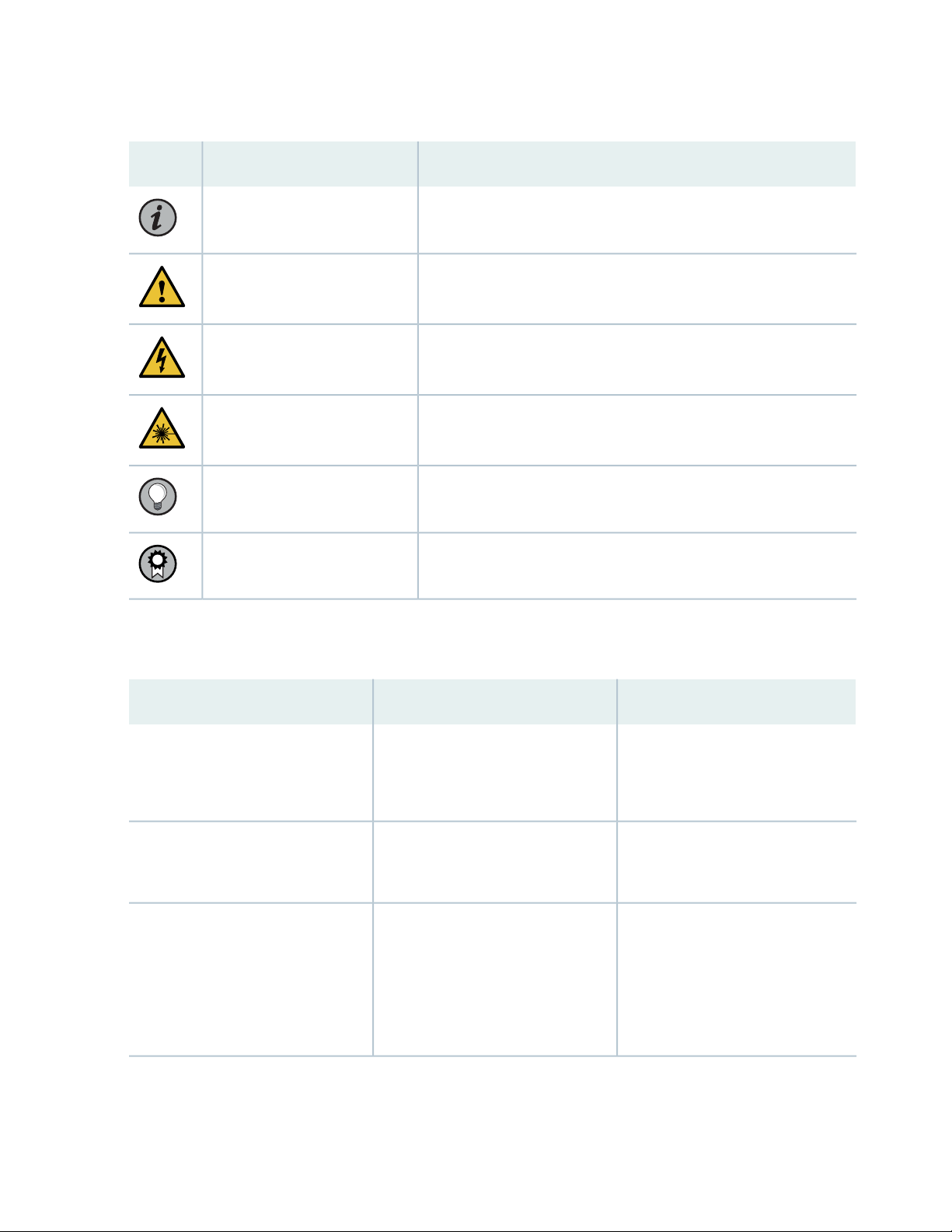
Table 1: Notice Icons
xiv
DescriptionMeaningIcon
Indicates important features or instructions.Informational note
Caution
Indicates a situation that might result in loss of data or hardware
damage.
Alerts you to the risk of personal injury or death.Warning
Alerts you to the risk of personal injury from a laser.Laser warning
Indicates helpful information.Tip
Alerts you to a recommended use or implementation.Best practice
Table 2 on page xiv defines the text and syntax conventions used in this guide.
Table 2: Text and Syntax Conventions
ExamplesDescriptionConvention
Fixed-width text like this
Italic text like this
Represents text that you type.Bold text like this
Represents output that appears on
the terminal screen.
Introduces or emphasizes important
•
new terms.
Identifies guide names.
•
Identifies RFC and Internet draft
•
titles.
To enter configuration mode, type
the configure command:
user@host> configure
user@host> show chassis alarms
No alarms currently active
A policy term is a named structure
•
that defines match conditions and
actions.
Junos OS CLI User Guide
•
RFC 1997, BGP Communities
•
Attribute
Page 15

Table 2: Text and Syntax Conventions (continued)
xv
ExamplesDescriptionConvention
Italic text like this
Text like this
< > (angle brackets)
| (pipe symbol)
Represents variables (options for
which you substitute a value) in
commands or configuration
statements.
Represents names of configuration
statements, commands, files, and
directories; configuration hierarchy
levels; or labels on routing platform
components.
variables.
Indicates a choice between the
mutually exclusive keywords or
variables on either side of the symbol.
The set of choices is often enclosed
in parentheses for clarity.
Configure the machine’s domain
name:
[edit]
root@# set system domain-name
domain-name
To configure a stub area, include
•
the stub statement at the [edit
protocols ospf area area-id]
hierarchy level.
The console port is labeled
•
CONSOLE.
stub <default-metric metric>;Encloses optional keywords or
broadcast | multicast
(string1 | string2 | string3)
# (pound sign)
[ ] (square brackets)
Indention and braces ( { } )
; (semicolon)
GUI Conventions
Indicates a comment specified on the
same line as the configuration
statement to which it applies.
Encloses a variable for which you can
substitute one or more values.
Identifies a level in the configuration
hierarchy.
Identifies a leaf statement at a
configuration hierarchy level.
rsvp { # Required for dynamic MPLS
only
community name members [
community-ids ]
[edit]
routing-options {
static {
route default {
nexthop address;
retain;
}
}
}
Page 16
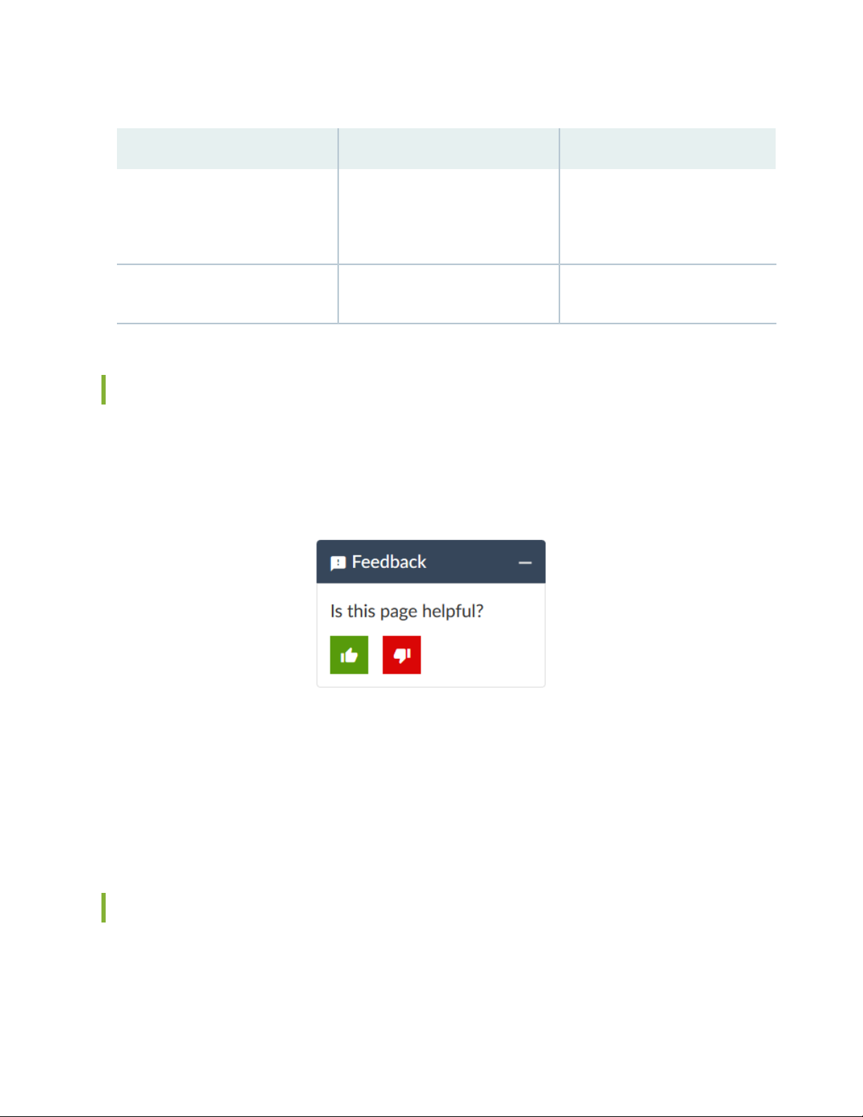
Table 2: Text and Syntax Conventions (continued)
xvi
ExamplesDescriptionConvention
Bold text like this
> (bold right angle bracket)
Represents graphical user interface
(GUI) items you click or select.
Separates levels in a hierarchy of
menu selections.
In the Logical Interfaces box, select
•
All Interfaces.
To cancel the configuration, click
•
Cancel.
In the configuration editor hierarchy,
select Protocols>Ospf.
Documentation Feedback
We encourage you to provide feedback so that we can improve our documentation. You can use either
of the following methods:
Online feedback system—Click TechLibrary Feedback, on the lower right of any page on the Juniper
•
Networks TechLibrary site, and do one of the following:
Click the thumbs-up icon if the information on the page was helpful to you.
•
Click the thumbs-down icon if the information on the page was not helpful to you or if you have
•
suggestions for improvement, and use the pop-up form to provide feedback.
E-mail—Send your comments to techpubs-comments@juniper.net. Include the document or topic name,
•
URL or page number, and software version (if applicable).
Requesting Technical Support
Technical product support is available through the Juniper Networks Technical Assistance Center (JTAC).
If you are a customer with an active Juniper Care or Partner Support Services support contract, or are
Page 17

covered under warranty, and need post-sales technical support, you can access our tools and resources
online or open a case with JTAC.
JTAC policies—For a complete understanding of our JTAC procedures and policies, review the JTAC User
•
Guide located at https://www.juniper.net/us/en/local/pdf/resource-guides/7100059-en.pdf.
Product warranties—For product warranty information, visit https://www.juniper.net/support/warranty/.
•
JTAC hours of operation—The JTAC centers have resources available 24 hours a day, 7 days a week,
•
365 days a year.
Self-Help Online Tools and Resources
For quick and easy problem resolution, Juniper Networks has designed an online self-service portal called
the Customer Support Center (CSC) that provides you with the following features:
Find CSC offerings: https://www.juniper.net/customers/support/
•
Search for known bugs: https://prsearch.juniper.net/
•
xvii
Find product documentation: https://www.juniper.net/documentation/
•
Find solutions and answer questions using our Knowledge Base: https://kb.juniper.net/
•
Download the latest versions of software and review release notes:
•
https://www.juniper.net/customers/csc/software/
Search technical bulletins for relevant hardware and software notifications:
•
https://kb.juniper.net/InfoCenter/
Join and participate in the Juniper Networks Community Forum:
•
https://www.juniper.net/company/communities/
Create a service request online: https://myjuniper.juniper.net
•
To verify service entitlement by product serial number, use our Serial Number Entitlement (SNE) Tool:
https://entitlementsearch.juniper.net/entitlementsearch/
Creating a Service Request with JTAC
You can create a service request with JTAC on the Web or by telephone.
Visit https://myjuniper.juniper.net.
•
Call 1-888-314-JTAC (1-888-314-5822 toll-free in the USA, Canada, and Mexico).
•
For international or direct-dial options in countries without toll-free numbers, see
https://support.juniper.net/support/requesting-support/.
Page 18

1
CHAPTER
Overview
QFX5100 System Overview | 19
QFX5100 Chassis Description and Port Panels | 33
QFX5100 Management Panel | 55
QFX5100 Power System | 64
QFX5100 Cooling System | 75
Page 19
QFX5100 System Overview
IN THIS SECTION
QFX5100 Device Hardware Overview | 19
QFX5100 Device Models | 28
Understanding Hardware Redundancy of QFX5100 Device Components and Functionality | 31
Field-Replaceable Units in a QFX5100 Device | 32
QFX5100 Device Hardware Overview
19
IN THIS SECTION
QFX5100 Hardware | 19
System Software | 28
The QFX5100 line of 10/40GbE switches delivers low latency, flexible deployment options, and rich
automation features. QFX5100 Switches build a strong underlay foundation for flexible, high-performance,
standards-based fabrics and routing that improve network reliability and agility.
QFX5100 Hardware
QFX5100 line of switches offer two compact 1 U models and a 2 U model that provide wire-speed packet
performance, very low latency, and rich set of Layer 2 and Layer 3 features. In addition to a high-throughput
Packet Forwarding Engine, the performance of the control plane running on all the QFX5100 switches is
enhanced by the 1.5 Ghz dual-core Intel CPU with 8 GB of memory and 32 GB of solid-state drive (SSD)
storage.
The QFX5100-24Q-AA switch has a 2.5 GHz 4-core Intel CPU with 32 GB of memory and 128 GB of SSD
storage.
The QFX5100 line of switches include both 10GE and 40GE fixed-configurations:
QFX5100-48S
•
Page 20
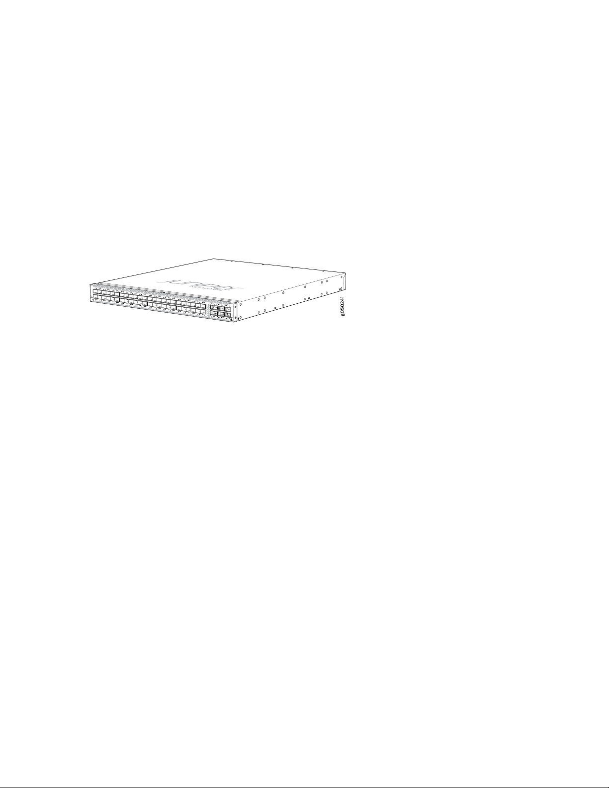
As shown in Figure 1 on page 20, the QFX5100-48S is a 10-Gigabit Ethernet Enhanced Small Form-Factor
Pluggable (SFP+) top-of-rack switch with 48 SFP+ ports and 6 Quad SFP+ (QSFP+) ports. Each SFP+
port can operate as a native 10 Gigabit port, when 10 Gbps optics are used. The SFP+ ports can also
run at 1 Gbps, or at 100 Mbps speeds when 1_Gigabit optics are inserted. Each QSFP+ port (48 through
53) can operate as uplink ports or four QSFP+ port (50 through 53) can operate at native 40-Gigabit
speed or as 4 independent 10-Gigabit port speeds. The 6 QSFP+ ports can be used as either access
ports or as uplinks. The QFX5100-48S provides full duplex throughput of 1.44 Tbps. The QFX5100-48S
has a 1 U form factor and comes standard with redundant fans and redundant power supplies. The switch
can be ordered with either ports-to-FRUs or FRUs-to-ports airflow and with AC or DC power supplies.
Figure 1: QFX5100-48S Port Panel
20
The QFX5100-48S can be used as:
A standalone switch.
•
A Node device in a QFabric system.
•
The QFX5100-48S is supported on both the QFX3000-G and QFX3000-M QFabric systems.
A primary, backup, or line card in a QFX Virtual Chassis.
•
A QFX Virtual Chassis allows you to interconnect up to 10 QFX3500, QFX3600, or QFX5100 switches
into one logical device and manage the device as a single chassis using a ring topology.
A line card in a QFX5110 Virtual Chassis.
•
A QFX5110 Virtual Chassis must have a QFX5110-32Q as the primary. Only QFX5110 and select
models of QFX5100 can participate in a QFX5110 Virtual Chassis.
A spine or leaf device in a standard QFX5100 Virtual Chassis Fabric (VCF).
•
VCF uses Virtual Chassis technology to interconnect multiple devices into a single logical device and
manage that device as a single logical device inside of a fabric architecture. VCF architecture supports
up to 20 total devices in a spine and leaf topology. Out of the 20 total devices, you can configure a
maximum of 4 spine devices.
A QFX5100 VCF uses QFX5100 devices as spines or leaf devices. You can also use QFX3500, QFX3600,
and EX4300 models as leaf devices in a QFX5100 VCF.
Whenever possible, configure the QFX5100-24Q as the spine device in a QFX5100 VCF. You can use
the QFX5100-48S as the spine in an all QFX5100-48S VCF or when EX4300 devices are used as leaf
devices.
Page 21
A leaf device in a QFX5110 VCF.
•
A QFX5110 VCF must have a minimum of two QFX5110-32Q as spine devices. Junos OS Release
17.3R1 or later is required for QFX5110 VCF.
A satellite device in a Junos Fusion system.
•
Junos OS Release 14.2.3 or later is required for Junos Fusion.
QFX5100-48SH
•
As shown in Figure 2 on page 21, the QFX5100-48SH is the same form factor and port configuration
as the QFX5100-48S. The QFX5100-48SH is specifically designed for Junos Fusion and comes
pre-configured with Satellite Network Operational System (SNOS) instead of Juniper Networks Junos
OS. The switch may not be converted to Junos OS without an additional license. The switch can be
ordered with either ports-to-FRUs or FRUs-to-ports airflow and with AC power supplies.
The QFX5100-48SH can only be used as a satellite device in a Junos Fusion system.
Figure 2: QFX5100-48SH Port Panel
21
QFX5100-48T
•
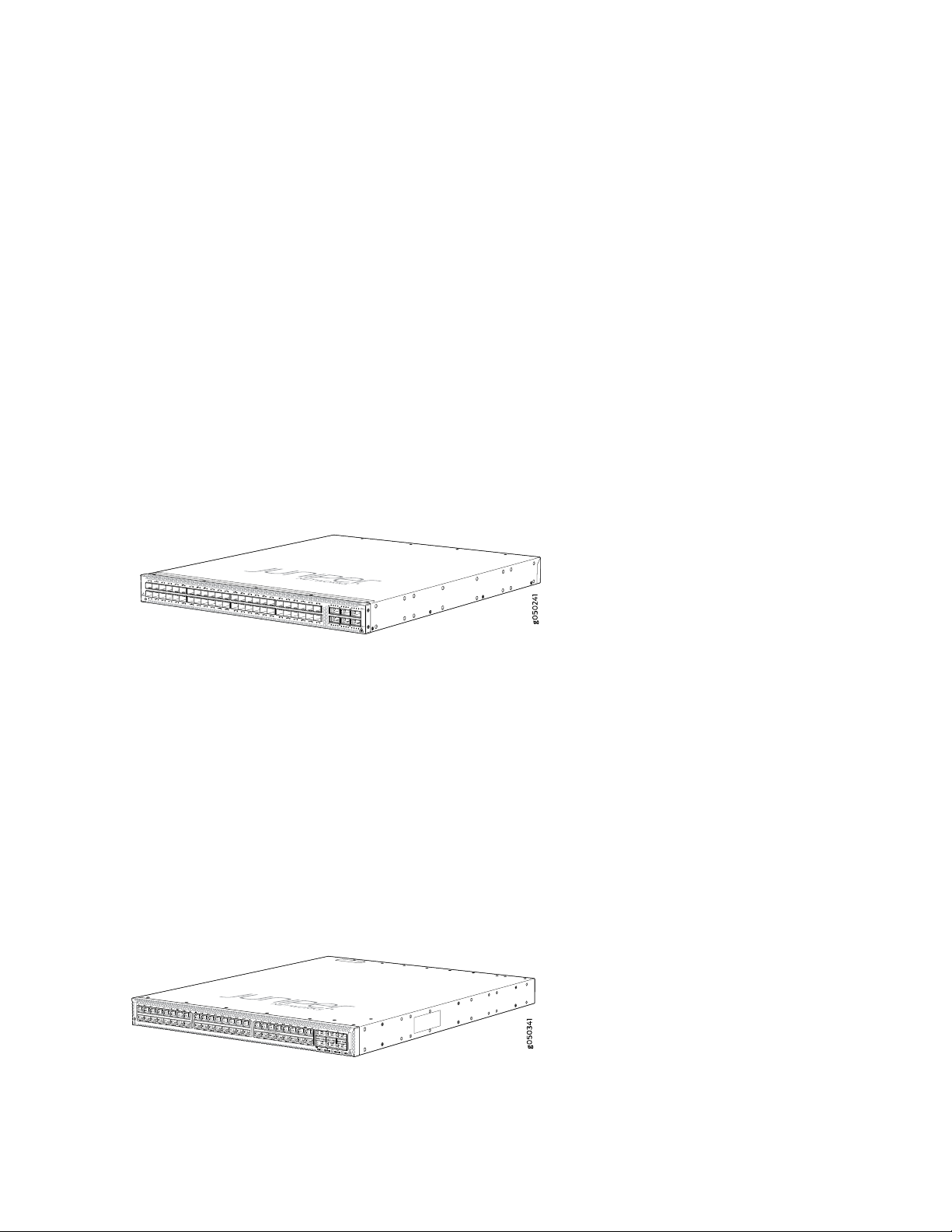
As shown in Figure 3 on page 21, the QFX5100-48T is a tri-speed 100/1000/10GBASE-T top-of-rack
switch with 48 10GBASE-T access ports and 6 QSFP+ ports. Each 40-Gigabit QSFP+ port (48 through
53) can operate either as uplink ports or four QSFP+ ports (50 through 53) can operate at native
40-Gigabit port or be channelized into 4 independent 10 Gigabit ports. The 6 QSFP+ ports can be used
as either access ports or as uplinks. The QFX5100-48T provides full duplex throughput of 720 Gbps.
The QFX5100-48T has a 1 U form factor and comes standard with redundant fans and redundant power
supplies. The switch can be ordered with either ports-to-FRUs or FRUs-to-ports airflow and with AC or
DC power supplies.
Figure 3: QFX5100-48T Port Panel
The QFX5100-48T can be used as:
Page 22

A standalone switch.
•
A Node device in a QFabric system.
•
The QFX5100-48T is supported on both the QFX3000-G and QFX3000-M QFabric systems.
A primary, backup, or line card in a QFX Virtual Chassis.
•
A QFX Series Virtual Chassis allows you to interconnect up to ten QFX5100, QFX3500, or QFX3600,
switches into one logical device and manage the device as a single chassis using a ring topology.
A line card in a QFX5110 Virtual Chassis.
•
You can configure up to ten QFX5110 and QFX5100 switches into one logical device and manage the
device as a single chassis using a ring topology. In a QFX5110 Virtual Chassis, configure QFX5110-32Q
as the primary and backup. Junos OS Release 17.3R2 or later is required on all members for QFX5110
VCF with QFX5100-48T leaf devices.
A leaf device in a standard QFX5100 Virtual Chassis Fabric (VCF).
•
VCF uses Virtual Chassis technology to interconnect multiple devices into a single logical device and
manage that device as a single logical device inside of a fabric architecture. VCF architecture supports
up to 20 total devices in a spine and leaf topology. Of those 20 devices, four QFX5100 devices can
be configured as spine devices.
22
In a QFX5100 VCF, the QFX5100-48T is always a leaf device and a QFX5100-24Q is the spine device.
A leaf device in a QFX5110 VCF.
•
A QFX5110 VCF must have a minimum of two QFX5110-32Q as spine devices. Junos OS Release
17.3R2 or later is required on all VCF devices for QFX5100-48T leaf devices to operate in a QFX5110
VCF.
A satellite device in a Junos Fusion system.
•
Junos OS Release 14.2.3 or later is required for Junos Fusion.
QFX5100-48TH
•
As shown in Figure 4 on page 23, the QFX5100-48TH is the same form factor and port configuration
as the QFX5100-48T. The QFX5100-48TH is specifically designed for Junos Fusion and comes
pre-configured with Satellite Network Operational System (SNOS) instead of Juniper Networks Junos
OS. The switch may not be converted to Junos OS without an additional license. The switch can be
ordered with either ports-to-FRUs or FRUs-to-ports airflow and with AC power supplies.
The QFX5100-48TH can only be used as a satellite device in a Junos Fusion system.
Page 23
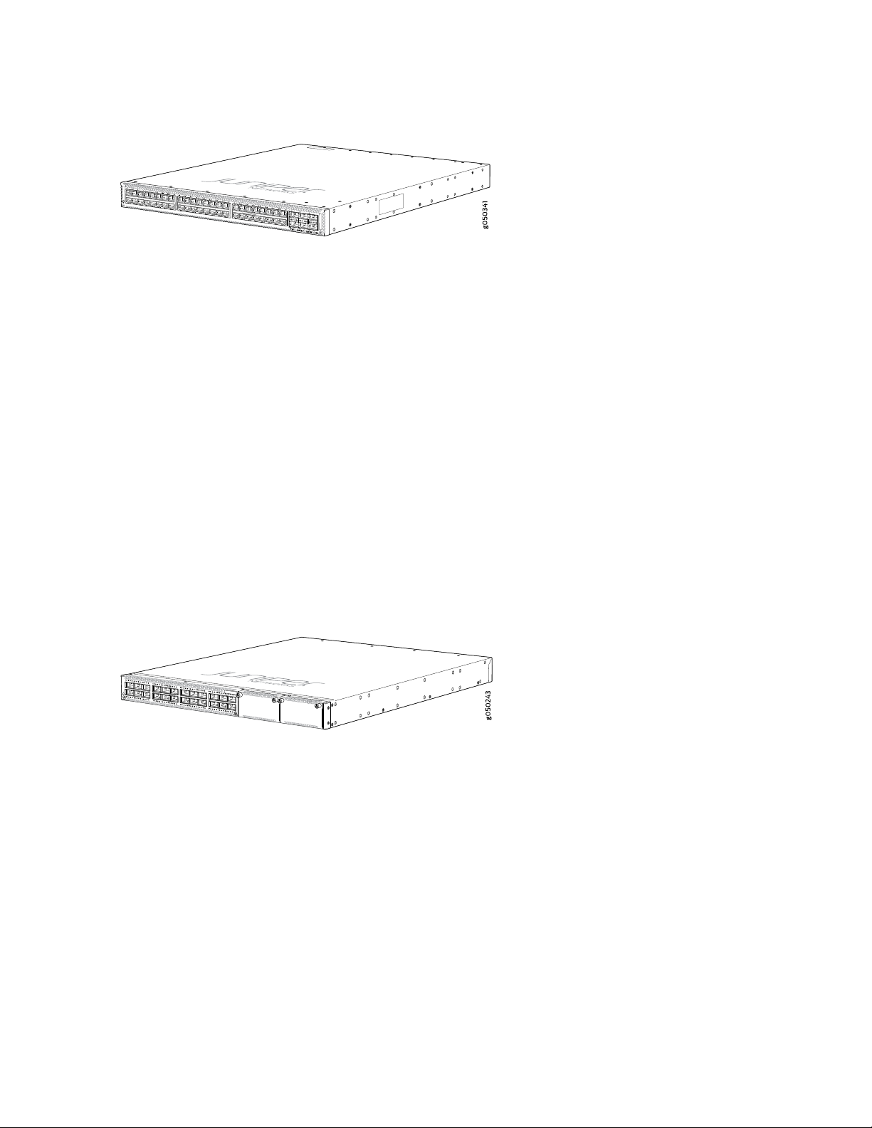
Figure 4: QFX5100-48THPort Panel
QFX5100-24Q
•
As shown in Figure 5 on page 23, the QFX5100-24Q is a 40-Gigabit Ethernet QSFP+ switch with 24
high-density QSFP+ ports. Each QSFP+ port can operate as a native 40 Gbps port or as 4 independent
10 Gbps ports. The QFX5100-24Q switch has a 1 U form factor and comes standard with redundant
fans and redundant power supplies. The switch can be ordered with either ports-to-FRUs or FRUs-to-ports
airflow and with AC or DC power supplies.
The QFX5100-24Q switch has two module bays for the optional expansion module, QFX-EM-4Q, which
can add a total of 8 additional QSFP+ ports to the chassis. When operating as a standalone switch and
fully populated with QFX-EM-4Q Expansion Modules, the QFX5100-24Q switch is equivalent to 80
10 Gbps interfaces and 4 40-Gbps interfaces. Of these total ports, 104 logical ports are available for
10G port channelization. For full details on the different port channelization modes, see “Port Panel of
a QFX5100-24Q Device” on page 34. All ports on the QFX5100-24Q and QFX-EM-4Q can be configured
as either access ports or as uplinks. The QFX5100-24Q switch provides full duplex throughput of 2.56
Tbps.
23
Figure 5: QFX5100-24Q Port Panel
The QFX5100-24Q can be used as:
A standalone switch.
•
An interconnect device in a QFX3000-M QFabric system.
•
A Node device in a QFabric system.
•
The QFX5100-24Q is supported on both the QFX3000-G and QFX3000-M QFabric systems. A
QFX5100-24Q Node device is equivalent to 80 10-Gbps interfaces and 4 40-Gbps interfaces.
A primary, backup, or line card in a QFX Virtual Chassis.
•
A QFX Series Virtual Chassis allows you to interconnect up to 10 QFX3500, QFX3600, or QFX5100
switches into one logical device and manage the device as a single chassis in a ring topology.
Use QFX5100-24Q switches as the primary and backup in a QFX Virtual Chassis.
Page 24
A line card in a QFX5110 Virtual Chassis.
•
A QFX5110 Virtual Chassis must have a QFX5110-32Q as the primary. Only QFX5110 switches and
select models of QFX5100 can participate in a QFX5110 Virtual Chassis. Junos OS Release 17.3R1
or later is required for QFX5110 Virtual Chassis.
A spine or leaf device in a standard QFX5100 Virtual Chassis Fabric (VCF).
•
VCF uses Virtual Chassis technology to interconnect multiple devices into a single logical device and
manage that device as a single logical device inside of a fabric architecture. VCF architecture supports
up to 20 total devices in a spine and leaf topology. Out of the 20 total devices, you can configure a
maximum of 4 spine devices.
A QFX5100 VCF uses QFX5100 devices as spines or leaf devices. You can also use QFX3500, QFX3600,
and EX4300 models as leaf devices in a QFX5100 VCF.
Whenever possible, configure the QFX5100-24Q as the spine device in a QFX5100 VCF.
A leaf device in a QFX5110 VCF.
•
A QFX5110 VCF must have a minimum of two QFX5110-32Q as spine devices. Junos OS Release
17.3R1 or later is required for QFX5110 VCF.
24
A satellite device in a Junos Fusion system.
•
Junos OS Release 14.2.3 or later is required for Junos Fusion.
The QFX5100-24Q switch has two bays on the port panel for optional expansion modules. The
QFX5100-24Q supports two expansion modules to increase port density:
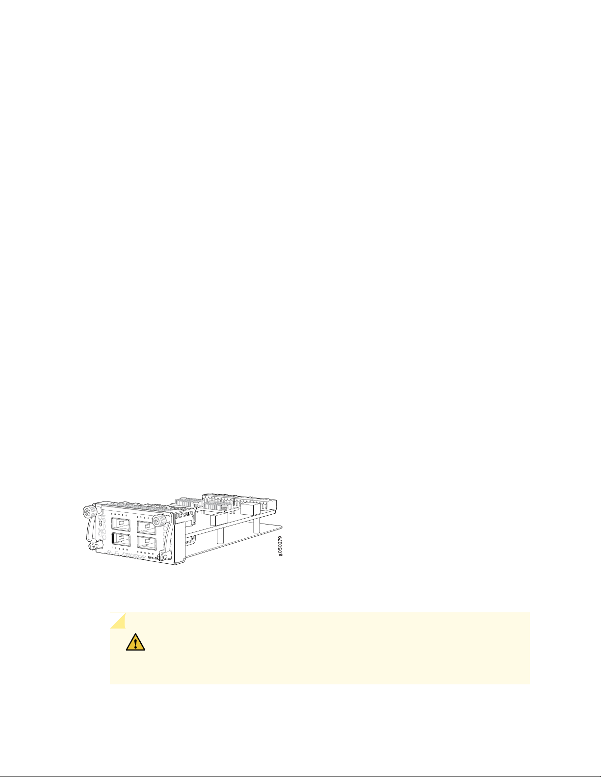
QFX-EM-4Q, which provides four additional 40-Gigabit Quad SFP+ (QSFP+) ports. See
•
Figure 6 on page 24.
Figure 6: QFX-EM-4Q Expansion Module
EX4600-EM-8F, which provides eight additional 10-Gigabit Ethernet Enhanced Small Form-Factor
•
Pluggable (SFP+) or four 1-Gigabit Ethernet ports. See Figure 7 on page 25.
CAUTION: Use only the top four ports or the bottom four ports for SFP
transceivers. Because SFP transceivers are larger than SFP+ transceivers, attempting
to stack SFP transceivers can cause internal damage to the module.
Page 25
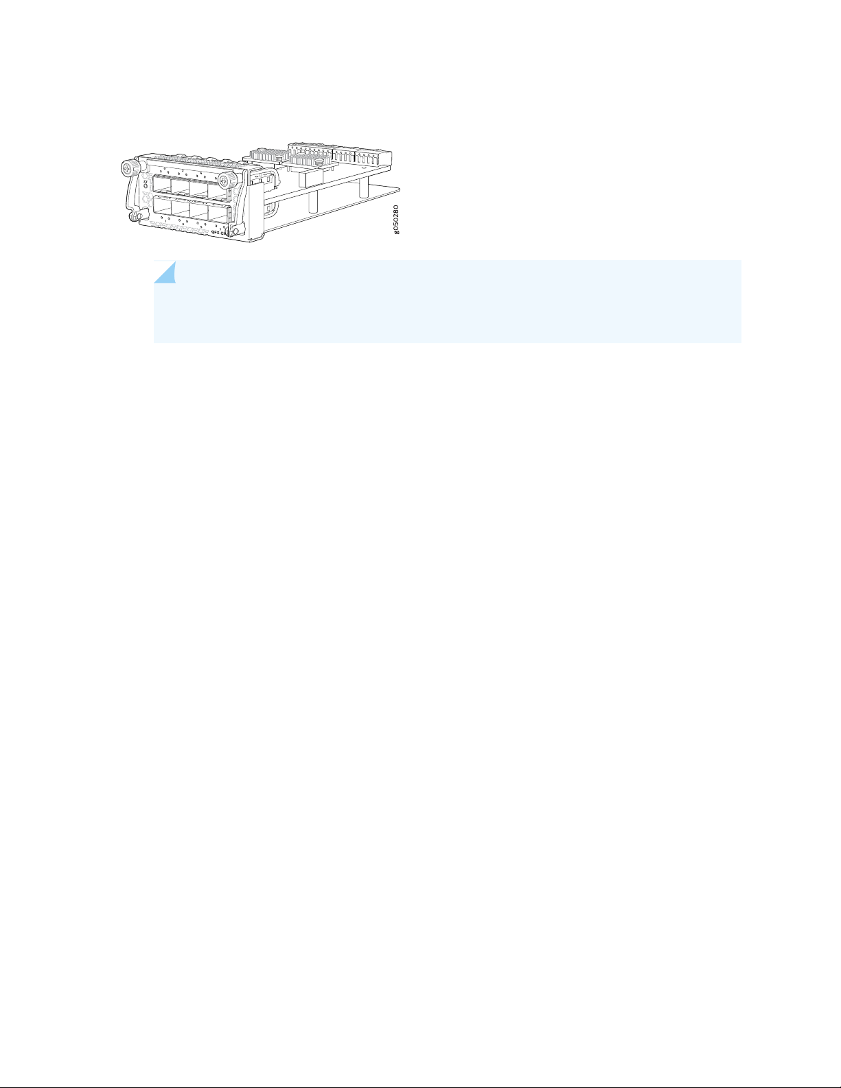
Figure 7: EX4600-EM-8F Expansion Module
NOTE: The EX4600-EM-8F is not supported on the QFX5100-24Q running in QFabric
systems.
The QFX5100-24Q is configured for the QFX-EM-4Q by default, but any combination of the two modules
is supported. Expansion modules can be hot-inserted or hot-removed. However, when an EX4600-EM-8F
is inserted instead of the default QFX-EM-4Q, the new configuration causes the interfaces to temporarily
go down. Likewise, when an EX4600-EM-8F is running on the QFX5100-24Q and it is swapped with a
QFX-EM-4Q, the interfaces temporarily go down, which can cause a short disruption in traffic.
25
QFX5100-24Q-AA
•
As shown in Figure 8 on page 26, the QFX5100-24Q-AA is a 1 U, top-of-rack, 40-Gigabit Ethernet
QSFP+ switch with 24 high-density QSFP+ ports. Each QSFP+ port can be configured to support
40-Gigabit Ethernet or as a set of 4 independent 10-Gigabit Ethernet ports. The QFX5100-24Q-AA can
also be configured to support twenty-four 40-Gigabit Ethernet interfaces or ninety-six 10-Gigabit
Ethernet interfaces using breakout cables (channelization mode) with 1280 Gbps output. The switch
can be ordered with either ports-to-FRUs or FRUs-to-ports airflow and with AC or DC power supplies.
The QFX5100-24Q switch provides full duplex throughput of 2.56 Tbps.
The QFX5100-24Q-AA module bay can accommodate a single Packet Flow Accelerator (PFA) double-wide
expansion module (QFX-PFA-4Q) or two single-wide optional expansion modules (two or one each of
QFX-EM-4Q and EX4600-EM-8F). The QFX-PFA-4Q, which features a high-performance
field-programmable gate array (FPGA), provides four additional QSFP+ ports to the chassis. Each
QFX-EM-4Q adds four QSFP+ ports to the chassis and each EX4600-EM-8F adds eight 10-Gigabit SFP+
ports to the chassis. The QFX-EM-4Q ports can also be configured as either access ports or uplink ports,
but only ports 0 and 2 can be channelized using port mode. For full details on the different port
channelization modes, see “Port Panel of a QFX5100-24Q Device” on page 34. All ports on the
QFX5100-24Q and QFX-EM-4Q can be configured as either access ports or uplink ports.
This switch provides the hardware support to enable PTP boundary clocks by using the QFX-PFA-4Q
module. The QFX5100-24Q-AA also supports GPS in and out signals when QFX-PFA-4Q is installed.
The CPU subsystem of this switch includes a 2-port 10-Gigabit Ethernet network interface card (NIC)
to provide a high bandwidth path or to alternate traffic path to guest VMs directly from the Packet
Forwarding Engine.
Page 26
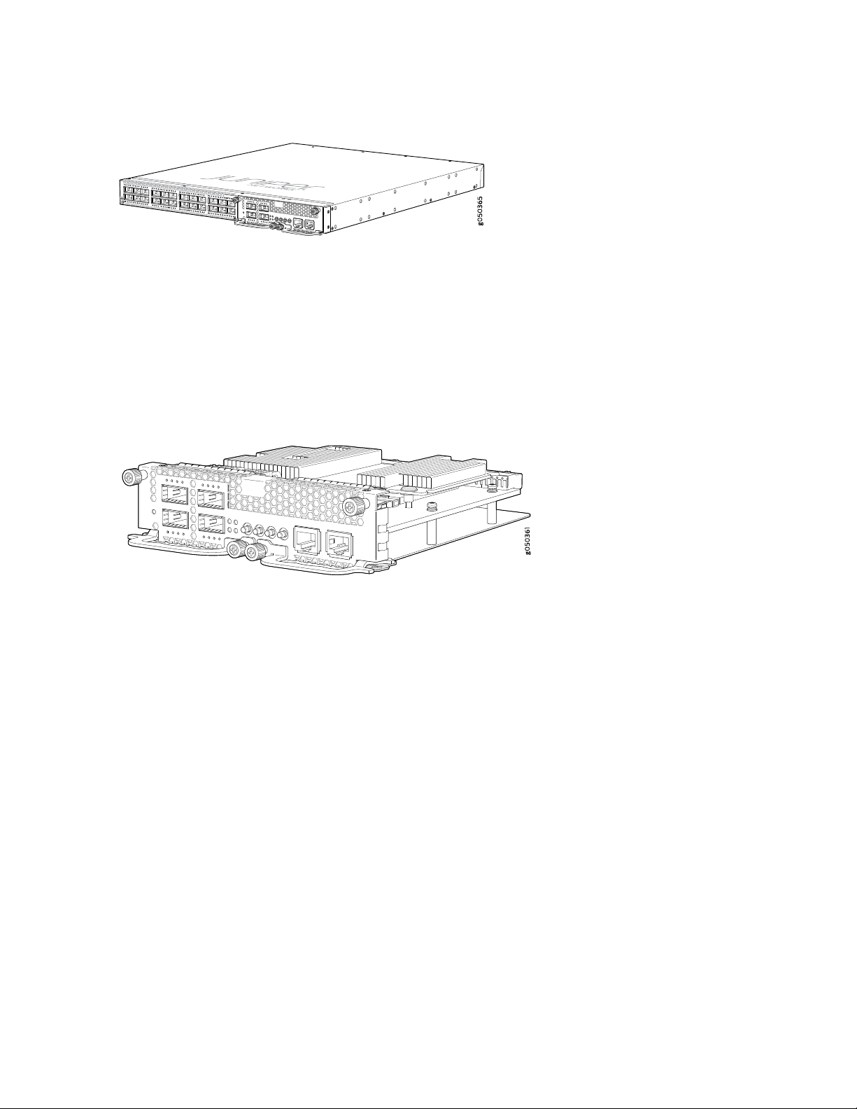
Figure 8: QFX5100-24Q-AA Port Panel with QFX-PFA-4Q
The QFX5100-24Q-AA can be used as a standalone switch that supports high frequency statistics
collection. Working with Juniper Networks Cloud Analytics Engine, this switch monitors and reports the
workload and application behavior across the physical and virtual infrastructure.
The QFX5100-24Q-AA supports the following expansion modules to increase port density:
QFX-PFA-4Q (double-wide), which provides four additional QSFP+ ports. See Figure 9 on page 26.
•
Figure 9: QFX-PFA-4Q Expansion Module
26
QFX-EM-4Q (single-wide), which provides 4 additional 40-Gigabit Ethernet QSFP+ ports. See
•
Figure 6 on page 24.
EX4600-EM-8F (single-wide), which provides 8 additional 10-Gigabit Ethernet SFP+ ports. See
•
Figure 7 on page 25.
The QFX5100-24Q switch supports the QFX-PFA-4Q and you must take the switch offline before
replacing the expansion module. Any combination of EX4600-EM-8F and QFX-EM-4Q is also supported.
These two expansion modules can be hot-inserted or hot-removed. However, when an EX4600-EM-8F
is inserted instead of a QFX-EM-4Q, the new configuration causes the interfaces to temporarily go
down. Likewise, when an EX4600-EM-8F is running on the QFX5100-24Q and is swapped with a
QFX-EM-4Q, the interfaces temporarily go down, which can cause a short disruption in traffic.
QFX5100-96S
•
As shown in Figure 10 on page 27, the QFX5100-96S switch is a is a 10-Gigabit Ethernet Enhanced
Small Form-Factor Pluggable (SFP+) top-of-rack switch with 96 SFP+ ports and 8 Quad SFP+ (QSFP+)
ports. Each SFP+ port can operate as a native 10 Gigabit port, when 10 Gbps optics are used. The SFP+
ports can also run at 1 Gbps, or at 100 Mbps speeds when 1_Gigabit optics are inserted. QSFP+ ports
96 and 100 can operate at native 40 Gbps speed or can be channelized to 4 independent 10 Gbps port
speeds. The 8 QSFP+ ports can be used as either access ports or as uplinks. The QFX5100-96S switch
Page 27
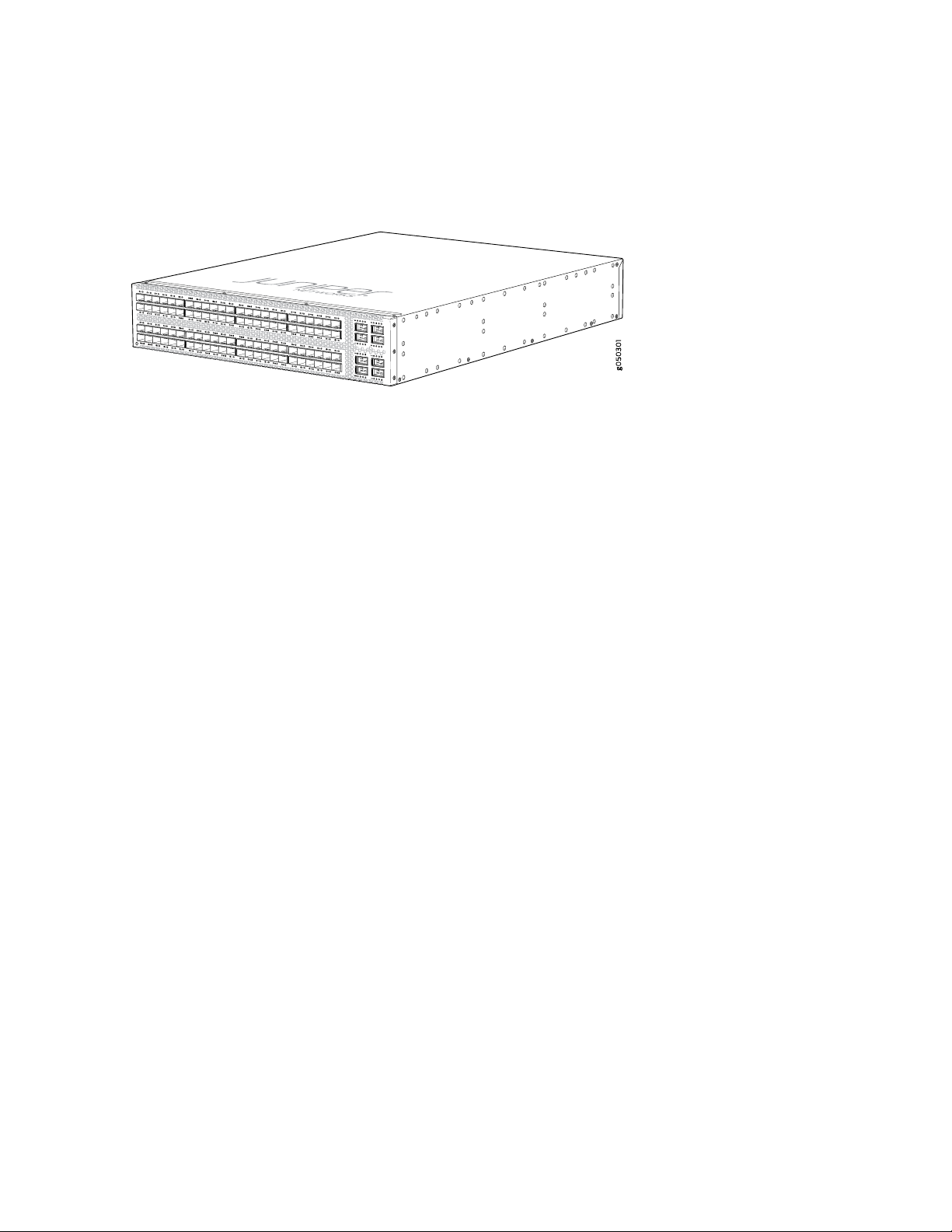
has a 2 U form factor and comes standard with redundant fans and redundant power supplies. The switch
can be ordered with either ports-to-FRUs or FRUs-to-ports airflow and with AC or DC power supplies.
Figure 10: QFX5100-96S Port Panel
The QFX5100-96S can be used as:
A standalone switch.
•
A member in a QFX Virtual Chassis.
•
27
A QFX Series Virtual Chassis allows you to interconnect up to ten QFX3500, QFX3600, or QFX5100
switches into one logical device and manage the device as a single chassis in a ring topology.
A spine or leaf device in a Virtual Chassis Fabric (VCF).
•
VCF uses Virtual Chassis technology to interconnect multiple devices into a single logical device and
manage that device as a single logical device inside of a fabric architecture. VCF architecture supports
up to 20 total devices in a spine and leaf topology. Of those 20 devices, 4 QFX5100 devices can be
configured as spine devices.
In a mixed environment with QFX5100-24Q, QFX5100-98S and EX4300, use the QFX5100-24Q as
the spine device and the QFX5100-96S and EX4300 as a leaf devices. You may use the QFX5100-96S
as a spine in an all QFX5100-96S VCF or in a VCF that has a mixture of QFX5100-96S and EX4300.
A line card in a mixed QFX5110 Virtual Chassis.
•
A QFX5110 Virtual Chassis must have a QFX5110-32Q as the primary. Only QFX5110 switches and
select models of QFX5100 switches can participate in a QFX5110 Virtual Chassis. Junos OS Release
17.3R1 or later is required for QFX5110 Virtual Chassis.
A spine or leaf device in a standard QFX5100 Virtual Chassis Fabric (VCF).
•
VCF uses Virtual Chassis technology to interconnect multiple devices into a single logical device and
manage that device as a single logical device inside of a fabric architecture. VCF architecture supports
up to 20 total devices in a spine and leaf topology. Out of the 20 total devices, you can configure a
maximum of 4 spine devices.
A QFX5100 VCF uses QFX5100 devices as spines or leaf devices. You can also use QFX3500, QFX3600,
and EX4300 models as leaf devices in a QFX5100 VCF.
Whenever possible, configure the QFX5100-24Q as the spine device in a QFX5100 VCF.
Page 28

A leaf device in a QFX5110 VCF.
•
A QFX5110 VCF must have a minimum of two QFX5110-32Q as spine devices. Junos OS Release
17.3R1 or later is required for QFX5110 VCF.
A satellite device in a Junos Fusion system.
•
Junos OS Release 14.2.3 or later is required for Junos Fusion.
System Software
QFX Series devices use the Junos operating system (OS), which provides Layer 2 and Layer 3 switching,
routing, and security services. Junos OS is installed on a QFX5100 switch’s 32-gigabyte (GB) internal solid
state flash drive. The same Junos OS code base that runs on QFX5100 switches also runs on all Juniper
Networks EX Series switches, M Series, MX Series, and T Series routers.
Participation in a QFX5110 Virtual Chassis or a QFX5110 VCF requires the same Junos OS image on all
devices in the Virtual Chassis or VCF. Junos OS 17.3R1 or later is the minimum software release for
QFX5110 Virtual Chassis or QFX5110 VCF.
28
For more information about which features are supported on QFX Series devices, see Feature Explorer.
You manage the switch using the Junos OS command-line interface (CLI), accessible through the console
and out-of-band management ports on the device.
SEE ALSO
Plan a Virtual Chassis Fabric Deployment | 95
QFX5100 Device Models
The QFX5100 switches have 24, 48, or 96 port configurations. The 24 port switches can be expanded to
a maximum of 32 QSFP+ ports using expansion modules. All switches are available with either AC or DC
power supply and with either airflow-in or airflow-out cooling. In legacy switches, or switches with an
LCD, this air flow is called front-to-back and back-to-front.
Table 3 on page 29 lists the ordering numbers for QFX5100 switch product SKUs.
Page 29

Table 3: QFX5100 Switch Product Numbers
29
Number of
Expansion
ModulesPortsP roduct Numbers
24 QSFP+QFX5100-24Q-AA
expansion
modules and
has 2
expansion
module slots
Power
Supply
Number
of Mgt.
Ports
2ACSupports 3
2AC224 QSFP+QFX5100-24Q-AFI
3AC224 QSFP+QFX5100-24Q-3AFI
2AC224 QSFP+QFX5100-24Q-AFO
3AC224 QSFP+QFX5100-24Q-3AFO
Airflow
Air In
(FRUs-to-ports)
and Air Out
(ports-to-FRUs)
Air In
(FRUs-to-ports)
Air In
(FRUs-to-ports)
Air Out
(ports-to-FRUs)
Air Out (portsto-FRUs)
QFX5100-48S-AFI
pluggable plus (SFP+ )
and 6 QSFP+
transceivers
2DC224 QSFP+QFX5100-24Q-DC-AFI
3DC224 QSFP+QFX5100-24Q-D-3AFI
2DC224 QSFP+QFX5100-24Q-DC-AFO
3DC224 QSFP+QFX5100-24Q-D-3AFO
2AC48 small form-factor
Air In
(FRUs-to-ports)
Air In
(FRUs-to-ports)
Air Out
(ports-to-FRUs)
Air Out
(ports-to-FRUs)
Air In
(FRUs-to-ports)
Page 30
Table 3: QFX5100 Switch Product Numbers (continued)
30
QFX5100-48S-3AFI
QFX5100-48S-AFO
QFX5100-48S-3AFO
QFX5100-48S-DC-AFI
QFX5100-48S-DC-AFO
pluggable plus (SFP+ )
and 6 QSFP+
transceivers
transceivers
transceivers
transceivers
transceivers
Number of
Expansion
ModulesPortsP roduct Numbers
Power
Supply
Number
of Mgt.
Ports
3AC48 small form-factor
2AC48 SFP+ and 6 QSFP+
3AC48 SFP+ and 6 QSFP+
2DC48 SFP+ and 6 QSFP+
2DC48 SFP+ and 6 QSFP+
Airflow
Air In
(FRUs-to-ports)
Air Out
(ports-to-FRUs)
Air Out
(ports-to-FRUs)
Air In
(FRUs-to-ports)
Air Out
(ports-to-FRUs)
QFX5100-48SH-AFI
QFX5100-48SH-AFO
QFX5100-48T-AFI
QFX5100-48T-AFO
QFX5100-48T-DC-AFI
QFX5100-48T-DC-AFO
QFX5100-48TH-AFI
transceivers
transceivers
QSFP+ transceivers
QSFP+ transceivers
QSFP+ transceivers
QSFP+ transceivers
QSFP+ transceivers
3AC48 SFP+ and 6 QSFP+
3AC48 SFP+ and 6 QSFP+
3AC48 10GBASE-T and 6
3AC48 10GBASE-T and 6
3DC48 10GBASE-T and 6
3DC48 10GBASE-T and 6
3AC48 10GBASE-T and 6
Air In
(FRUs-to-ports)
Air Out
(ports-to-FRUs)
Air In (FRUs to
ports)
Air Out (ports to
FRUs)
Air In (FRUs to
ports)
Air Out (ports to
FRUs)
Air In (FRUs to
ports)
Page 31

Table 3: QFX5100 Switch Product Numbers (continued)
31
QFX5100-48TH-AFO
QFX5100-96S-AFI
QFX5100-96S-AFO
QFX5100-96S-DC-AFI
QFX5100-96S-DC-AFO
CAUTION: Mixing different types (AC and DC) of power supplies in the same chassis
is not supported. Mixing different airflow modules in the same chassis is not supported.
QSFP+ transceivers
transceivers
transceivers
transceivers
transceivers
Number of
Expansion
ModulesPortsP roduct Numbers
Power
Supply
Number
of Mgt.
Ports
3AC48 10GBASE-T and 6
2AC96 SFP+ and 8 QSFP+
2AC96 SFP+ and 8 QSFP+
2DC96 SFP+ and 8 QSFP+
2DC96 SFP+ and 8 QSFP+
Airflow
Air Out (ports to
FRUs)
Air In
(FRUs-to-ports)
Air Out
(ports-to-FRUs)
Air In
(FRUs-to-ports)
Air Out
(ports-to-FRUs)
SEE ALSO
QFX5100 Management Panel | 55
Understanding Hardware Redundancy of QFX5100 Device Components and Functionality
The following hardware components provide redundancy on a QFX5100 switch:
Power supplies—The QFX5100 switch has one or two power supplies. Each power supply provides
•
power to all components in the switch. If two power supplies are installed, the two power supplies
provide full power redundancy to the device. If one power supply fails or is removed, the second power
supply balances the electrical load without interruption.
Page 32

To provide power redundancy to the system both power supplies must be installed. Connect power
source feed A to one power supply and power source feed B to the second power supply.
CAUTION: Do not connect feed A and feed B to the same power supply input
terminal.
Cooling system—The 1 U models of QFX5100 line of switches have five fan modules; the 2 U
•
QFX5100-96S has three fan modules. If a fan module fails and is unable to keep the QFX5100 switch
within the desired temperature thresholds, chassis alarms occur and the QFX5100 switch can shut down.
SEE ALSO
QFX5100 Power System | 64
QFX5100 Cooling System | 75
32
Field-Replaceable Units in a QFX5100 Device
Field-replaceable units (FRUs) are components that you can replace at your site. The QFX5100 device
FRUs are hot-insertable and hot-removable: you can remove and replace one of them without powering
off the switch or disrupting the switching function.
CAUTION: Replace a failed power supply with a blank panel or new power supply
within one minute of removal to prevent chassis overheating. The switch continues
to operate with only one power supply running. Replace a failed fan module with a
new fan module within one minute of removal to prevent chassis overheating. Do not
operate the switch with missing FRUs for longer than one minute.
Table 4 on page 32 lists the FRUs for the QFX5100 device and actions to take before removing them.
Table 4: FRUs in a QFX5100 Switch
Required ActionFRU
None.Power supplies
NoneExpansion modules
Page 33

Table 4: FRUs in a QFX5100 Switch (continued)
Required ActionFRU
None.Fan modules
33
Optical transceivers
None. We recommend that you disable the interface using the set interfaces
interface-name disable command before you remove the transceiver. See
Disconnecting a Fiber-Optic Cable from a QFX Series Device.
NOTE: If you have a Juniper Care service contract, register any addition, change, or upgrade of
hardware components at https://www.juniper.net/customers/support/tools/updateinstallbase/
. Failure to do so can result in significant delays if you need replacement parts. This note does
not apply if you replace existing components with the same type of component.
RELATED DOCUMENTATION
QFX5100 Management Panel | 55
QFX5100 Chassis Description and Port Panels
IN THIS SECTION
Chassis Physical Specifications for a QFX5100 Device | 34
Port Panel of a QFX5100-24Q Device | 34
Port Panel of a QFX5100-24Q-AA Device | 39
Port Panel of QFX5100-48S and QFX5100-48SH Devices | 39
Port Panel of QFX5100-48T and QFX5100-48TH Devices | 42
Port Panel of a QFX5100-96S Device | 44
Expansion Modules for QFX5100 Devices | 47
Access Port and Uplink Port LEDs on a QFX5100 Device | 51
Page 34

Chassis Physical Specifications for a QFX5100 Device
The QFX5100 switch chassis is a rigid sheet-metal structure that houses the hardware components.
Table 5 on page 34 summarizes the physical specifications of the QFX5100 chassis.
Table 5: Physical Specifications for the QFX5100 Switch Chassis
WeightDepthWidthHeightProduct SKU
34
QFX5100-48SH
QFX5100-48TH
17.36 in. (44.1 cm)3.46 in. (8.8 cm)QFX5100-96S
SEE ALSO
QFX5100 Site Guidelines and Requirements | 88
20.48 in. (52 cm)17.36 in. (44.1 cm)1.72 in. (4.3 cm)QFX5100-24Q
20.48 in. (52 cm)17.36 in. (44.1 cm)1.72 in. (4.3 cm)QFX5100-24Q-AA
20.48 in. (52 cm)17.36 in. (44.1 cm)1.72 in. (4.3 cm)QFX5100-48S and
21.47 in. (54.5 cm)17.36 in. (44.1 cm)1.72 in. (4.3 cm)QFX5100-48Tand
22.44 in. (57 cm) (not
including handles for
Fans and PSUs)
With FRUs installed: 22 lbs
( 9.97 kg)
With FRUs installed: 25 lbs
( 11.4 kg)
With FRUs installed: 21.8
lbs (9.8 kg)
With FRUs installed: 24.79
lbs (11.2 kg)
With FRUs installed: 32 lbs
(14.5 kg)
Mount a QFX5100 Device in a Rack or Cabinet | 120
QFX5100 Standalone Installation Overview | 114
Installing and Removing QFX5100 Device Hardware Components | 180
Port Panel of a QFX5100-24Q Device
IN THIS SECTION
Switch Ports | 35
QFabric Systems | 36
Page 35

Channelizing Interfaces (Non-QFabric) | 36
Virtual Chassis and Virtual Chassis Fabric | 37
Port LEDs | 38
The port panel of the QFX5100-24Q device consists of 24 quad small-form factor pluggable plus (QSFP+)
ports. Each QSFP+ socket can be configured to support 40 GbE or as a set of 4 independent 10 GbE ports
using breakout cables (channelization mode). In standalone mode, any of the 24 ports 0 through 23 can
be configured as either uplink or access ports. The QFX5100-24Q device has two module bays for the
optional expansion modules, QFX-EM-4Q or EX4600-EM-8F. The QFX-EM-4Q, can add a total of 8
additional QSFP+ ports to the chassis and the EX4600-EM-8F can provide 8 additional 10-Gigabit Ethernet
Enhanced Small Form-Factor Pluggable (SFP+) ports. The QFX-EM-4Q ports can also be configured as
either access ports or as uplinks, but only ports 0 and 2 can be channelized using port mode.
Figure 11 on page 35 shows the port panel of the QFX5100-24Q device.
35
Figure 11: QFX5100-24Q Device Port Panel
3—1— Expansion module bays with cover panels (2)Electrostatic Discharge (ESD) terminal
2—QSFP+ access interface or uplink ports (24)
Switch Ports
The QFX5100-24Q device ports, (0 through 23) support:
40 Gbps QSFP+ transceivers
•
QSFP+ to QSFP+ direct attach copper (DAC) cables
•
QSFP+ to SFP+ direct attach copper break out (DACBO) cables
•
QSFP+ to QSFP+ active optical cables (AOC)
•
QSFP+ to SFP+ active optical breakout cable (AOCBO)
•
Access ports
•
You can use 40-Gigabit Ethernet QSFP+ transceivers and QSFP+ direct attach copper cables in any
downstream port. See “Determining Interface Support for the QFX5100 Device” on page 98.
Page 36

Uplink ports
•
You can configure up to 4 of the 40 GbE ports as uplinks. Each additional QFX-EM-4Q, Expansion
Module adds the switch uplink capacity by 2 for a total of 8 uplinks.
To connect a QFX5100-24Q switch as a Node device in a QFabric system, you need:
Four QSFP+ uplink ports on each QFX5100-24Q Node device to connect to the data plane network
•
through the QFX3008-I or QFX5100-24Q Interconnect devices.
Two additional QSFP+ uplink ports on each QFX5100-24Q Node device connect to the data plane
•
network through the QFX3008-I or QFX5100-24Q Interconnect devices. .
QFabric Systems
The QFX5100-24Q operates as a Node device in both the QFX3000-G and QFX3000-M QFabric systems.
Additionally, the QFX5100-24Q can be configured as an Interconnect Device in QFX3000-M QFabric
systems allowing a maximum of 16 Node devices. The QFX5100-24Q may not be mixed with QFX3600-I
Interconnect devices in the same QFabric system.
36
When operating as a Node device, ports 0 through 7 are default FTE ports; ports 8 through 15 can be
configured as either uplink (FTE) or access ports (XLE). In the port range 8 through 23, only 12 ports can
be channelized when the 2 QFX-EM-4Q are installed.
NOTE: The EX4600-EM-8S expansion module is not supported on the QFX5100-24Q device
in a QFabric system.
Channelizing Interfaces (Non-QFabric)
When fully populated with 2 QFX-EM-4Q Expansion Modules, the QFX5100-24Q device has 128 physical
ports. However, only 104 logical ports can be used for port channelization. Depending on the system mode
you configure for channelization, different ports are restricted. If you attempt to channelize a restricted
port, the configuration is ignored. The following system modes are available on the QFX5100-24Q device:
Default mode
•
All 24 QSFP+ ports on the switch (PIC 0) are channelized by default (96 ports). With QFX-EM-4Q
Expansion Modules (PIC 1) and (PIC 2), the QSFP+ ports are supported for access or uplink ports, but
cannot be channelized. Ports are over-subscribed In this mode and could be subject to packet-loss. You
can have one of two port combinations: 32 40-Gbps QSFP+ ports, or 96 10-Gigabit Ethernet ports plus
8 40-Gbps QSFP+ ports.
104 port mode
•
Page 37

All 24 QSFP+ ports on the switch (PIC 0) are channelized (96 ports). Two ports on QFX-EM-4Q Expansion
Module (PIC 1) are also channelized (8 additional). In this mode, ports 0 and 2 are channelized by default
and ports 1 and 3 are disabled. If additional QSFP+ ports are detected in an expansion module (PIC 2),
those ports are ignored.
Flexi-pic mode
•
Ports 0 through 3 of the switch cannot be channelized; ports 4 through 24 are channelized by default
(80 ports). With QFX-EM-4Q Expansion Modules (PIC 1) and (PIC 2), the QSFP+ ports are supported
for access or uplink ports, but cannot be channelized. With EX4600-EM-8F Expansion Modules installed
(PIC 1) and (PIC 2), the 16 SFP+ ports of SFP are recognized for a total of 96 logical ports.
Non-oversubscribed mode
•
All 24 QSFP+ ports on the switch (PIC 0) are channelized (96 ports). Expansion modules on PIC 1 and
PIC 2 are not supported and cannot be channelized. There is no packet loss for packets of any size in
this mode.
Virtual Chassis and Virtual Chassis Fabric
37
The QFX5100-24Q device operates as a standalone switch, a member of a QFX Virtual Chassis, or as a
spine or leaf device in a QFX5100 Virtual Chassis Fabric (VCF). QFX Virtual Chassis support up to 10
members. QFX5100 VCF supports 20 QFX5100 and EX4300 devices, of which 4 QFX5100 devices can
be configured as spines.
To connect a QFX5100-24Q device as a member in a QFX Virtual Chassis, you need to cable a pair of
ports to link each member in the Virtual Chassis into a ring topology. Each member in the ring has at least
one direct Virtual Chassis port (VCP) connection to each directly connected member. QFX5100-24Q
devices are recommended in the primary, backup, or line card role. When mixed with QFX3500 or QFX3600
devices, configure the QFX5100-24Q device in the primary and backup roles. See “Connecting QFX Series
and EX Series Switches in a QFX Virtual Chassis” on page 127 for cabling diagrams. The Virtual Chassis
feature is not applicable to QFX devices in a QFabric.
To connect a QFX5100-24Q device as a spine or leaf device in a QFX5100 VCF, you need to cable a set
of ports as VCP connections that link each spine device and leaf device. All spine devices have at least one
direct VCP connection to each leaf device in the VCF. Non-channelized DAC cables can be configured as
VCP connections. See “Connecting a QFX5100 Device in a Virtual Chassis Fabric” on page 134 for a cabling
diagram.
BEST PRACTICE: Whenever possible use the QFX5100-24Q device as a spine device. By using
the QFX5100-24Q device in a maximum configuration of 20 total devices, four QFX5100-24Q
devices may be used as spine devices. All members can be connected to the spine using QSFP+
ports.
Page 38

As of Junos OS release 17.3R1, you can also connect a QFX5100-24Q as a leaf device in a QFX5110 VCF
or as a member in a QFX5110 Virtual Chassis.
Port LEDs
The bi-color LEDs labeled Link/Activity LED in Figure 12 on page 38 indicate link activity or faults.
Figure 12: LEDs on the QSFP+ Uplink Ports
38
Table 6 on page 38 describes the SFP+ access port LEDs.
Table 6: Port LEDs on a QFX5100-24Q Switch
DescriptionStateColor
OffUnlit
On steadilyGreen
Blinking
The port is administratively disabled, there is no power, or there
is a fault.
NOTE: When configured for channelized 10-Gigabit Ethernet,
the LED remains unlit only if all four of the 10-Gigabit Ethernet
SFP+ breakout links are down.
A link is established, but there is no link activity.
NOTE: When configured for channelized 10-Gigabit Ethernet,
the LED is lit green when at least one of the four 10-Gigabit
Ethernet SFP+ breakout links is established.
A link is established, and there is link activity.
NOTE: When configured for channelized 10-Gigabit Ethernet,
the LED is lit green when at least one of the four 10-Gigabit
Ethernet SFP+ breakout links is established.
BlinkingAmber
All four LEDs blink to indicate the beacon function was enabled
on the port.
Page 39

Port Panel of a QFX5100-24Q-AA Device
The port panel of the QFX5100-24Q-AA switch consists of 24 quad small-form factor pluggable plus
(QSFP+) 40-Gigabit Ethernet ports. Each QSFP+ socket can be configured to support 40-Gigabit Ethernet
or as a set of four independent 10-Gigabit Ethernet ports using breakout cables (channelization mode).
The QFX5100-24Q-AA can also be configured to support 96 10-Gigabit Ethernet ports using breakout
cables (channelization mode) with 1280 Gbps output. Any of the 24 ports can be configured as either an
uplink port or an access port.
The expansion module bay of the QFX5100-24Q switch is located on the port panel. In the expansion
module bay, you can install a single double-wide expansion module (QFX-PFA-4Q) or two single-wide
optional expansion modules (QFX-EM-4Q and EX4600-EM-8F, in any combination). When you install two
single-wide expansion modules, the slot on your left hand side is slot 1 (QIC0), and the slot on your right
hand side is slot 2 (QIC1).
The QFX-PFA-4Q module adds four QSFP+ ports to the chassis. The QFX-EM-4Q module adds four
QSFP+ ports to the chassis and the EX4600-EM-8F module adds eight 10-Gigabit SFP+ ports to the chassis.
The QFX-EM-4Q ports can be configured as either access ports or as uplinks ports, but only ports 0 and
2 can be channelized by using port mode. The QFX-EM-4Q ports can also be configured as either access
ports or uplink ports, but only ports 0 and 2 can be channelized by using port mode. Figure 13 on page 39
shows the port panel of the QFX5100-24Q-AA device.
39
Figure 13: Port Panel of a QFX5100-24Q-AA Switch
Electrostatic discharge (ESD) terminal
2—QSFP+ ports (24)
For details on port LEDs, see “Port LEDs on a QFX5100-24Q Switch” on page 38.
3—1— Expansion module bay (with a QFX-PFA-4Q
expansion module installed)
Port Panel of QFX5100-48S and QFX5100-48SH Devices
The port panel of the QFX5100-48S and QFX5100-48SH switches supports up to a maximum of 72 logical
10 GbE ports when operating as a standalone switch. Forty-eight physical ports(0 through 47) support 10
Gigabit Ethernet small form-factor pluggable plus (SFP+) transceivers. These ports can also support 1 Gigabit
SFP transceivers and can be configured at either 1 Gbps or 1 Gbps speeds using the set interface speed
Page 40

command. All 48 of these ports can be used for SFP+ transceivers or SFP+ direct attach copper (DAC)
cables. You can use 1-Gigabit Ethernet SFP+, 10-Gigabit Ethernet SFP+ transceivers and SFP+ DAC cables
in any access port.
The remaining 24 logical ports are the six 40 GbE physical ports (48 through 53) that support up to 6 quad
small-form factor pluggable plus (QSFP+) transceivers . Each QSFP+ socket can operate either as a single
40 Gbps port or as a set of 4 independent 10 Gbps ports using QSFP+ breakout cables. The 40 GbE ports
can be configured as either access ports or as uplinks.
CAUTION: Do not install 1GbE copper transceivers (such as QFX-SFP-1GE-T) directly
above or below another 1GbE copper transceiver. Use only the top row or bottom
row to avoid damage to the device caused by some types of copper transceivers when
the transceivers are installed above or below each other. However, if you are using
copper transceivers with the OEM part number FCLF8521P2BTL-J1 printed on the
transceiver label, you can install the transceivers in any port with no restrictions. For
devices that support 10GbE copper transceivers, there is no similar restriction.
40
To connect a QFX5100-48S switch as a node device in a QFabric system, you need:
Four QSFP+ uplink ports on each QFX5100-48S Node device to connect to the data plane network
•
through the QFX3008-I or QFX5100-24Q Interconnect devices.
The two remaining QSFP+ uplink ports on each QFX5100-48S Node device connect to the data plane
•
network through the QFX3008-I or QFX5100-24Q Interconnect devices. See “Determining Interface
Support for the QFX5100 Device” on page 98.
To connect a QFX5100-48S switch as a member in a QFX Virtual Chassis, you need a pair of dedicated
ports and cables that link each member in the Virtual Chassis into a ring topology. Each member in the
ring has at least one direct Virtual Chassis port (VCP) connection to a upstream and downstream member.
QFX5100-48S switches are recommended in the primary, backup, or line card role. When mixed with
QFX3500 or QFX3600 devices, configure the QFX5100-48S in the primary and backup roles. See
“Connecting QFX Series and EX Series Switches in a QFX Virtual Chassis” on page 127 for cabling diagrams.
To connect a QFX5100-48S switch as a spine or leaf device in a QFX5100 Virtual Chassis Fabric (VCF),
you need a pair of dedicated ports and cables that link each spine device and leaf device in the VCF. All
spine devices have at least one direct VCP connection to each leaf device in the VCF. See “Connecting a
QFX5100 Device in a Virtual Chassis Fabric” on page 134 for a cabling diagram.
Page 41

BEST PRACTICE: In a mixed QFX5100 VCF environment with multiple models of QFX5100 and
the EX4300, use QFX5100-24Q as spine devices. In the maximum configuration of 20 total
devices, up to four QFX5100-24Q devices may be used as spine devices. All members can be
connected to the spine using QSFP+ ports. You can configure the QFX5100-96S as a spine in
an all QFX5100-96S VCF or in a mixed VCF comprised of EX4300 and QFX5100-96S.
As of Junos OS release 17.3R1, you can also connect a QFX5100-48S as a leaf device in a QFX5110 VCF
or as a member in a QFX5110 Virtual Chassis.
Figure 14 on page 41 shows the port panel of a QFX5100-48S switch.
Figure 14: QFX5100-48S Switch Port Panel
41
3—1— 40 GbE ports (6)Electrostatic Discharge (ESD) terminal
2—10 G ports (48)
The QFX5100-48S and QFX5100-48SH device ports, (0 through 47) support:
SFP transceivers that can run at either 100 Mbps or 1 Gbps speed
•
SFP+ transceivers at 10 Gbps speed
•
SFP to SFP direct attach copper (DAC) cables
•
SFP+ to SFP+ DAC cables
•
SFP+ to SFP+ active optical cables (AOC)
•
The QFX5100-48S and QFX5100-48SH 40 G uplink or data ports (48 through 53) support:
QSFP+ transceivers
•
QSFP+ to QSFP+ direct attach copper (DAC) cables
•
QSFP+ to SFP+ DAC breakout cables (DACBO)
•
QSFP+ to QSFP+ active optical cables (AOC)
•
QSFP+ to SFP+ AOC breakout cables (AOCBO)
•
Page 42

Port Panel of QFX5100-48T and QFX5100-48TH Devices
The port panel of the QFX5100-48T and QFX5100-48TH devices supports 48 10GBASE-T ports and 6
quad small-form factor pluggable (QSFP+) ports. Forty-eight copper physical ports (0 through 47) are
tri-speed and support up to 10-Gigabit Ethernet. These 10GbE/1GbE/100 Mbps ports can be configured
as access ports. See “Determining Interface Support for the QFX5100 Device” on page 98.
The remaining six ports (48 through 53), support 40 GbE QSFP+ transceivers. Each QSFP+ socket can
operate either as a single 40 Gbps port or as a set of 4 independent 10 Gbps ports using QSFP+ breakout
cables. The 40 GbE ports can be configured as either access ports or as uplinks.
To connect a QFX5100-48T device as a member in a QFX Virtual Chassis, you need a pair of dedicated
ports and cables that link each member in the Virtual Chassis into a ring topology. Each member in the
ring has at least one direct Virtual Chassis port (VCP) connection to a upstream and downstream member.
QFX5100-48T switches are recommended in the primary, backup, or line card role. When mixed with
QFX3500 or QFX3600 devices, configure the QFX5100-48T device in the primary and backup roles. See
“Connecting QFX Series and EX Series Switches in a QFX Virtual Chassis” on page 127 for cabling diagrams.
42
To connect a QFX5100-48T device as a leaf device in a Virtual Chassis Fabric (VCF), you need a pair of
dedicated ports and cables that link each spine device and leaf device in the VCF. All spine devices have
at least one direct VCP connection to each leaf device in the VCF. See “Connecting a QFX5100 Device in
a Virtual Chassis Fabric” on page 134 for a cabling diagram.
The QFX5100-48T device operates as a standalone switch, a member of a QFX Virtual Chassis, a member
of a QFX5110 Virtual Chassis, act as a leaf device in a Juniper Networks Virtual Chassis Fabric (VCF). QFX
Virtual Chassis and QFX5100 Virtual Chassis both support up to 10 members. VCF supports 20 total
devices, of which 4 QFX5100-24Q devices can be configured as spine devices.
BEST PRACTICE: Use the QFX5100-24Q as a spine device and any QFX5100 device (except
QFX5100-24Q-AA, QFX5100-48TH, or QFX510048SH) as leaf devices.
Figure 15 on page 43 shows the port panel of a QFX5100-48T or QFX5100-48TH device.
Page 43

Figure 15: QFX5100-48T or QFX5100-48TH Switch Port Panel
3—1— 40 GbE ports (6)Electrostatic Discharge (ESD) terminal
2—10GBASE-T ports (48)
The QFX5100-48T and QFX5100-48TH device ports, (0 through 47) support RJ45 connectors. The 40 G
uplink or data ports (48 through 53) support:
QSFP+ transceivers
•
QSFP+ to QSFP+ direct attach copper (DAC) cables
•
QSFP+ to SFP+ DAC breakout cables (DACBO)
•
43
QSFP+ to QSFP+ active optical cables (AOC)
•
QSFP+ to SFP+ AOC breakout cables (AOCBO)
•
To connect a QFX5100-48T switch as a Node device in a QFabric system, you need:
Four QSFP+ uplink ports on each QFX5100-48T Node device to connect to the data plane network
•
through the QFX3008-I or QFX5100-24Q Interconnect devices.
The two remaining QSFP+ uplink ports on each QFX5100-48T Node device connect to the data plane
•
network through the QFX3008-I or QFX5100-24Q Interconnect devices.
Access port pinouts for the QFX5100-48T switch are the same as the management port connector pinouts
for the QFX Series. For more information, see “RJ-45 Management Port Connector Pinout Information”
on page 108.
SEE ALSO
Connect the QFX5100 in a Virtual Chassis or Virtual Chassis Fabric | 127
Page 44

Port Panel of a QFX5100-96S Device
IN THIS SECTION
Switch Ports | 44
Channelizing Interfaces | 45
Virtual Chassis and Virtual Chassis Fabric Support | 46
The port panel of the QFX5100-96S switch consists of 96 small form-factor pluggable plus (SFP+) and 8
quad small-form factor pluggable plus (QSFP+) ports that are normally configured as access ports. Physical
ports(0 through 95) support 10 Gbps SFP+ transceivers and 1 Gbps transceivers. The eight 40-Gigabit
ports (96 through 104) support QSFP+ transceivers and are normally configured as uplinks or Virtual
Chassis ports (VCPs). Although the 104 physical ports of the QFX5100-96S would map to 128 logical
ports using channelization, only 104 logical ports are supported.
44
Figure 16 on page 44 shows the port panel of a QFX5100-96S switch.
Figure 16: QFX5100-96S Switch Port Panel
3—1— 40 Gigabit Ethernet ports (8)Electrostatic Discharge (ESD) terminal
2—10 Gigabit Ethernet ports (96)
This topic describes:
Switch Ports
The QFX5100-96S switch ports, (0 through 95) support:
SFP transceivers that can run at either 100 Mbps or 1 Gbps speed
•
SFP+ transceivers at 10 Gbps speed
•
Page 45

SFP to SFP direct attach copper (DAC) cables
•
SFP+ to SFP+ DAC cables
•
SFP+ to SFP+ active optical cables (AOC)
•
Ports 96 through 104 support:
40 Gbps QSFP+ transceivers
•
Additionally ports 96 and 100 support:
SFP+ transceivers
•
QSFP+ to QSFP+ direct attach copper (DAC) cables
•
QSFP+ to SFP+ DAC breakout cables (DACBO)
•
QSFP+ to QSFP+ active optical cables (AOC)
•
QSFP+ to SFP+ AOC breakout cables (AOCBO)
•
45
CAUTION: Do not install 1GbE copper transceivers (such as QFX-SFP-1GE-T) directly
above or below another 1GbE copper transceiver. Use only the top row or bottom
row to avoid damage to the device caused by some types of copper transceivers when
the transceivers are installed above or below each other. However, if you are using
copper transceivers with the OEM part number FCLF8521P2BTL-J1 printed on the
transceiver label, you can install the transceivers in any port with no restrictions. For
devices that support 10GbE copper transceivers, there is no similar restriction.
Channelizing Interfaces
The port panel of the QFX5100-96S switch supports up to a maximum of 104 logical 10 GbE ports that
can be distributed over 96 small form-factor pluggable plus (SFP+) and 8 quad small-form factor pluggable
plus (QSFP+) transceivers . Because of an 104 port restriction, only two of the eight QSFP+ can be
channelized. Depending on how you set the system mode for channelization, the behavior of channelization
for the QSFP+ changes. The following system modes are available for the QFX5100-96S switch:
Non-oversubscribed
•
All 96 SFP+ ports on the switch (PIC 0) are supported. In this mode, the eight QSFP+ ports are not
supported and cannot be channelized. There is no packet loss for packets of any size in this mode.
Default mode
•
All 96 SFP+ ports on the switch (PIC 0) are supported. QSFP+ ports 96 and 100 can be channelized. If
ports 96 and 100 are channelized, the interfaces on ports 97, 98, 99, 101, 102, and 103 are disabled.
Page 46

Virtual Chassis and Virtual Chassis Fabric Support
The QFX5100-96S switch operates as a standalone switch, as a member in a QFX Virtual Chassis, as a
member in a QFX5110 Virtual Chassis, as a spine or leaf device in a QFX5100 Virtual Chassis Fabric (VCF),
or as a leaf device in a QFX5110 VCF. QFX Virtual Chassis support up to 10 members; QFX5100 VCF
supports a total of 20 devices, of which 4 QFX5100 devices can be configured as spines. A QFX Virtual
Chassis is cabled in a ring topology, where a VCF is cabled in a spine and leaf topology.
Virtual Chassis
In a QFX Virtual Chassis, you can connect up to 10 standalone QFX5100-96S switches into a QFX Series
Virtual Chassis and manage the interconnected switches as a single chassis. The advantages of connecting
multiple switches into a Virtual Chassis include better-managed bandwidth at a network layer, simplified
configuration and maintenance because multiple devices can be managed as a single device, increased
fault tolerance and high availability (HA) because a Virtual Chassis can remain active and network traffic
can be redirected to other member switches when a single member switch fails, and a flatter, simplified
Layer 2 network topology that minimizes or eliminates the need for loop prevention protocols such as
Spanning Tree Protocol (STP).
46
As of Junos OS release 17.3R1, you can also connect a QFX5100-96S as a member in a QFX5110 Virtual
Chassis.
Virtual Chassis Fabric
The VCF provides a low-latency, high-performance fabric architecture that can be managed as a single
device. VCF is an evolution of the Virtual Chassis feature, which allows you to interconnect multiple devices
into a single logical device, inside of a fabric architecture. The VCF architecture is optimized to support
small and medium-sized data centers that contain a mix of 1-Gpbs, 10-Gpbs, and 40-Gbps Ethernet
interfaces.
A VCF is constructed using a spine-and-leaf architecture and topology. In the spine-and-leaf architecture,
each spine device is interconnected to each leaf device. A VCF supports up to 20 devices, of which 4
QFX5100 devices can be configured into spine devices. In a mixed environment with QFX5100-24Q,
QFX5100-98S and EX4300, use the QFX5100-24Q as the spine device and the QFX5100-96S and EX4300
as a leaf devices. You may use the QFX5100-96S as a spine in an all QFX5100-96S VCF or in a VCF that
has a mixture of QFX5100-96S and EX4300.
As of Junos OS release 17.3R1, you can also connect a QFX5100-24Q as a leaf device in a QFX5110 VCF.
Page 47

Expansion Modules for QFX5100 Devices
IN THIS SECTION
EX4600-EM-8F | 47
QFX-EM-4Q | 49
QFX-PFA-4Q | 50
The QFX5100-24Q and QFX5100-24Q-AA devices have two bays on the port panel for optional expansion
modules. These expansion modules can be hot-inserted or hot-removed. Expansion modules and transceivers
are not shipped with the switch and must be ordered separately.
The QFX5100-24Q and QFX5100-24Q-AA support these expansion modules up to the 104-port limitation:
47
Two EX4600-EM-8F, which provides a total of 16 additional 10-Gigabit Ethernet Enhanced Small
•
Form-Factor Pluggable (SFP+) ports or 8 additional 1-Gigabit SFP ports. When both bays (PIC 1 and
PIC 2) are populated with EX4600-EM-8F modules, you must configure the system mode as Flexi-pic.
In this mode, port 0 to 3 of PIC 0 are disabled, which allows the devices to operate within the 104-port
limitation.
Two QFX-EM-4Q, which provides a total of 8 additional 40-Gigabit Quad SFP+ (QSFP+) ports.
•
One EX4600-EM-8F and one QFX-EM-4Q, which provides 8 additional 10-Gigabit Ethernet SFP+ (or
•
8 additional 1-Gigabit SFP ports) and 4 additional 40-Gigabit (QSFP+) ports. This combination requires
the system mode to be configured as Flexi-pic. See Configuring the System Mode.
Additionally, the QFX5100-24Q-AA supports the QFX-PFA-4Q expansion module, which provides 4
additional QSFP+ ports.
NOTE: In order to run the orchestration diagnostics, Precision Time Protocol (PTP) and
synchronization diagnostics, and utilities contained in the Packet Flow Accelerator Diagnostics
software, you must have Junos OS Release 14.1X53-D27 or later software with enhanced
automation installed on your QFX5100-24Q-AA.
EX4600-EM-8F
The EX4600-EM-8F is a MACsec-capable expansion module that inserts into one of the device bays of a
QFX5100-24Q, QFX5100-24Q-AA, or an EX4600 switch. It provides 8 additional 10-Gigabit Ethernet
Page 48

SFP+ ports or 8 additional 1-Gigabit SFP ports to each bay. Figure 17 on page 48 shows the ports and
LEDs on the expansion module.
CAUTION: Copper SFP transceivers (1000BASE-T) are restricted to the top four ports
or the bottom four ports; fiber SFP transceivers (1000BASE-X) can be used in any of
the eight ports. Attempting to stack copper SFP transceivers causes internal damage
to the module.
Figure 17: EX4600-EM-8F Faceplate and LEDs
48
2—1— SFP+ port LEDsExpansion module status LED
When the expansion module is inserted into the expansion bay, the chassis detects the additional ports,
recognizes them as 10GbE ports, and lights the Status LED. The QFX5100-24Q device is configured for
the QFX-EM-4Q by default, but any combination of the two modules is supported. Expansion modules
can be hot-inserted or hot-removed. However, when an EX4600-EM-4Q is inserted instead of the default
QFX-EM-4Q, the Packet Forwarding Engine reboots that can cause some temporary disruption in traffic.
See Configuring the System Mode.
NOTE: MACsec is supported on the 10-Gigabit Ethernet ports with the EX-QFX-MACSEC-AGG
license.
Table 7 on page 49 describes the Status LED on the EX4600-EM-8F.
Page 49
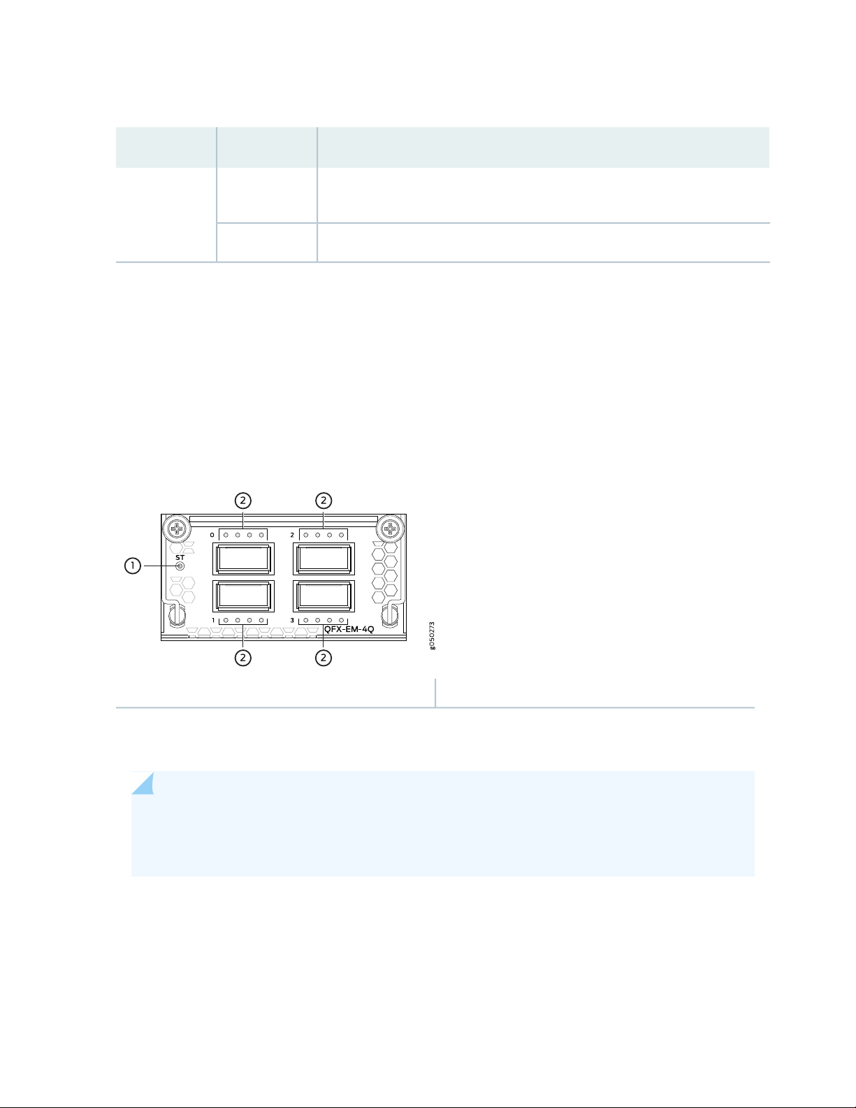
Table 7: EX4600-EM-8F Status LED
DescriptionStateLED
49
UnlitST
The expansion module is offline.
•
The chassis is powered off.
•
The expansion module is online and functioning normally.Green
•
QFX-EM-4Q
The QFX-EM-4Q, provides 4 additional 40-Gigabit Ethernet QSFP+ ports to one of the bays in the
QFX5100-24Q or QFX5100-24Q-AA. Port 0 and port 2 can be used for port channelization by configuring
the system mode for 104 port mode.
Figure 18 on page 49 shows the QFX-EM-4Q ports and LEDs.
Figure 18: QFX-EM-4Q Faceplate and LEDs
2—1— QSFP+ port LEDsExpansion module status LED
When the expansion module is inserted into the expansion bay, the chassis detects the additional ports,
recognizes them as 40 GbE ports, and lights the Status LED.
NOTE: If a QFX-EM-4Q is installed in PIC1 and EX4600-EM-8F is installed in PIC2, you must
configure the system mode to be Flexi-PIC. Otherwise, only the EQF-EM-4Q is recognized by
the software.
Table 8 on page 50 describes the Status LED on the QFX-EM-4Q expansion module.
Page 50

Table 8: Expansion Module Status LED
DescriptionStateLED
50
UnlitST
The expansion module is offline.
•
The chassis is powered off.
•
The expansion module is online and functioning normally.Green
•
QFX-PFA-4Q
The QFX-PFA-4Q, which features a high-performance field-programmable gate array (FPGA), provides
four additional QSFP+ ports to the QFX5100-24Q-AA switch. The QFX-PFA-4Q is a double-wide expansion
module. Figure 19 on page 50 shows the ports and LEDs on the expansion module.
Figure 19: QFX-PFA-4Q Faceplate and LEDs
4—1— 1-PPS and 10-MHz GPS input and outputExpansion module status LED
5—2— RJ-45 Ethernet portQSFP+ ports and LEDs
6—3— Time-of-day (TOD) RS-232 portFPGA LEDs
Table 9 on page 50 describes the status and FPGA LEDs on the QFX-PFA-4Q.
Table 9: QFX-PFA-4Q Status and FPGA LEDs
DescriptionStateLED
UnlitST
FPGA
The expansion module is offline.
•
The chassis is powered off.
•
The expansion module is online and functioning normally.Green
•
Page 51

Table 9: QFX-PFA-4Q Status and FPGA LEDs (continued)
DescriptionStateLED
FPGA not configured.OffLD
FPGA configuration in progress or failed.Amber
FPGA configured successfully.Green
No FPGA alarms.OffAL
Minor FPGA alarm.Amber
Major FPGA alarm.Red
Application-specific status is off.OffS0 and S1
51
Application-specific status is on.Green
SEE ALSO
Install and Remove Expansion Modules in a QFX5100-Device | 161
Configuring the System Mode
Access Port and Uplink Port LEDs on a QFX5100 Device
The Link/Activity and Status LED configuration for QFX5100 switches use bi-colored LEDs. The link LED
indicates link activity or a fault. The status LED indicates transceiver presence. See Table 10 on page 52
to locate the position and type of LED for your QFX5100 model.
Page 52

Table 10: QFX5100 Access Port and Uplink LED Locations
g050236
Bi-colored LEDs
LocationIndicatorsPort TypeModel
52
and
QFX5100-48SH
and
QFX5100-48TH
QSFP+QFX5100-24Q
Link
Status
SFP+QFX5100-48S
Link
Status
Link10GBASE-TQFX5100-48T
SFP+QFX5100-96S
Link
Status
Page 53

Table 10: QFX5100 Access Port and Uplink LED Locations (continued)
LocationIndicatorsPort TypeModel
53
Table 11 on page 53 describes how to interpret the SFP+ port LEDs.
Table 11: Network Port LEDs on SFP+ Ports on a QFX5100 Switch
DescriptionStateColorLED
The port is administratively disabled, there is no power,
the link is down, or there is a fault.
A link is established, but there is no link activity.On steadilyGreen
A link is established, and there is link activity.Blinking
The beacon is enabled on the port. On QFX5100-48T, it
indicates a fault.
The link is down.OffUnlitStatus
The beacon function is enabled on the port.BlinkingAmber
A 1-Gigabit Ethernet transceiver is installed in the port
and the link is established.
NOTE: Not
applicable for
QFX5100-48T or
QFX5100-48TH.
OffUnlitLink/Activity
BlinkingAmber
BlinkingGreen
On steadilyGreen
A 10-Gigabit Ethernet transceiver is installed in the port
and link is established.
Page 54

As shown in Table 10 on page 52, there are four bi-color LEDs for each QSFP+ port. The first LED is used
and the remaining LEDs are not used when the interface is configured for 40-Gigabit Ethernet and connected
to a QSFP+ transceiver. All four LEDs are used when the interface is configured for 10-Gigabit Ethernet
and the port is connected using an optical split cable or a copper DACBO cable. Table 12 on page 54
describes how to interpret the QSFP+ LEDs.
Table 12: Network Port LEDs on QSFP+ Ports on a QFX5100 Switch
DescriptionStateColor
54
OffUnlit
On steadilyGreen
Blinking
BlinkingAmber
The port is administratively disabled, there is no power, the
link is down, or there is a fault.
NOTE: When configured for 10-Gigabit Ethernet, the LED
remains unlit only if all four of the 10-Gigabit Ethernet SFP+
breakout links are down.
A link is established, but there is no link activity.
NOTE: When configured for 10-Gigabit Ethernet, the LED is
lit green when at least one of the four 10-Gigabit Ethernet
SFP+ breakout links is established.
A link is established, and there is link activity.
NOTE: When configured for 10-Gigabit Ethernet, the LED is
lit green when at least one of the four 10-Gigabit Ethernet
SFP+ breakout links is established.
All four LEDs blink to indicate the beacon function was enabled
on the port.
SEE ALSO
Management Panel of a QFX5100 Device | 55
Install and Remove Transceivers and Fiber Optic Cables on QFX5100 Devices | 168
RELATED DOCUMENTATION
Field-Replaceable Units in a QFX5100 Device | 32
Channelizing Interfaces on QFX3500, QFX3600, QFX5100, QFX10002, QFX10008, QFX10016, and
EX4600 Switches
Page 55
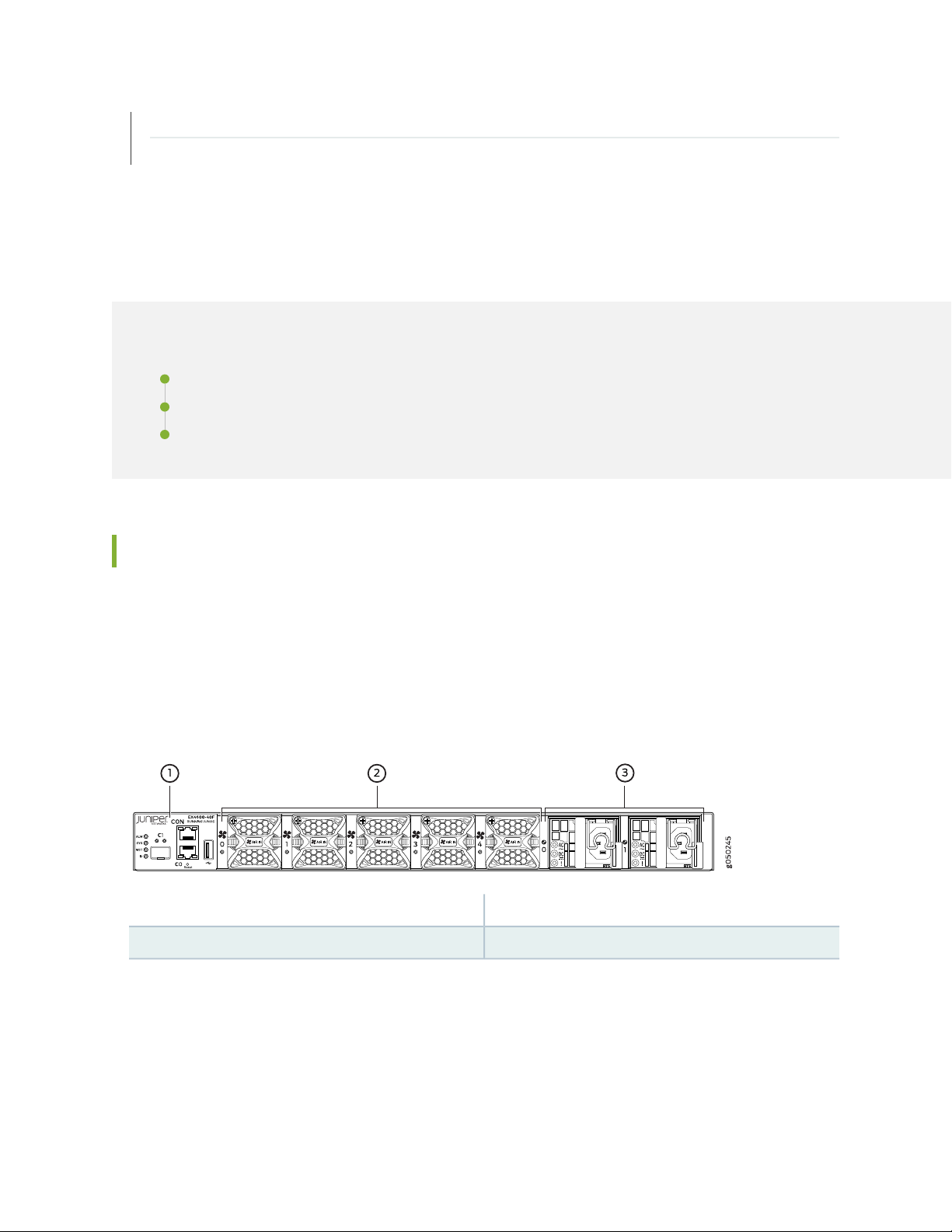
Installing and Removing QFX5100 Device Hardware Components | 180
Plan a Virtual Chassis Fabric Deployment | 95
QFX5100 Management Panel
IN THIS SECTION
Management Panel of a QFX5100 Device | 55
Management Port LEDs on a QFX5100 Device | 59
Chassis Status LEDs on a QFX5100 Device | 60
55
Management Panel of a QFX5100 Device
The management panel of the QFX5100 switch is found on the Field Replaceable Unit (FRU) end of the
switch as shown in Figure 20 on page 55 for 1 U switches and Figure 21 on page 56 for the 2 U ,
QFX5100-96S switch. See Figure 22 on page 56 and Figure 23 on page 57 for FRUs and management
panel detail.
Figure 20: QFX5100 Switch, FRU End 1 U Product SKUs
3—1— Power supply unitsManagement panel
2—Fan modules
Page 56

Figure 21: QFX5100-96S, FRU End
Figure 22: Management Panel Components on 1 U QFX5100
56
Status LEDs
Cage (socket for either 1 GbE copper SFP or fiber
SFP)
CAUTION: Do not use the Reset button to restart the power sequence unless under
the direction of Juniper Networks Technical Assistance Center (JTAC).
4—1— em0–RJ-45 (1000 Base-T) management Ethernet port
(C0)
Some SKUs have an additional SFP management
Ethernet port (second C0)
5—2— RJ-45 console port (CON) )em1–SFP management Ethernet port (C1)
6—3— USB portReset button, see caution statement below
Page 57

Figure 23: Management Panel Components on the QFX5100-96S
57
Status LEDs
Cage (socket for either 1 GbE copper SFP or fiber
SFP)
4—1— em0–RJ-45 (1000 Base-T) management Ethernet port
(C0)
5—2— RJ-45 console port (C0N) )em1–SFP management Ethernet port (C1)
6—3— USB portReset button, see caution statement above
The management panel consists of the following components:
Status LEDs
•
ALM–Alarm
•
Unlit indicates the switch is halted or that there is no alarm.
•
Red indicates a hardware fault, such as a power failure or a system shutdown due to system
•
over-heating.
Amber indicates a major or minor alarm.
•
SYS–System
•
Unlit indicates the switch is powered off or halted.
•
Solid green indicates that Junos OS for QFX Series is loaded on the switch.
•
Blinking green indicates the switch is:
•
A participating member in a Virtual Chassis.
•
A participating leaf device in a Virtual Chassis Fabric (VCF).
•
Page 58

A participating spine device in a VCF.
•
A Routing Engine Primary in a VCF.
•
A Routing Engine Backup in a VCF.
•
MST–Primary in a QFX Virtual Chassis or Routing Engine Primary in a VCF
•
Unlit indicates the switch is a line card member in a Virtual Chassis.
•
Solid green indicates the switch is:
•
A standalone switch
•
In the primary role in a QFX Virtual Chassis
•
Is the routing engine primary in a VCF
•
Blinking green indicates the switch is the backup primary in a Virtual Chassis or the backup routing
•
engine in a VCF.
ID–Identification or beacon
•
58
Unlit indicates the beacon feature is not enabled.
•
Blinking blue indicates the beacon feature is enabled. This feature is enabled using the request
•
chassis beacon command.
Switch product number
•
Management Ports C0 and C1
•
C0–Use the RJ-45 connectors for 10/100/1000 BaseT or to cable a virtual management Ethernet
•
(VME) interface for spine members in a VCF. See “Connect a Device to a Network for Out-of-Band
Management” on page 124.
NOTE: For product SKUs with C0 available in both copper and fiber, the copper C0 has
priority over fiber C0.
C1–Use the SFP connector for 1000 BaseX.
•
USB port for image updates.
•
Console port (RJ-45) to support RS-232 serial ports. The LEDs above the port indicate status and link.
•
Page 59
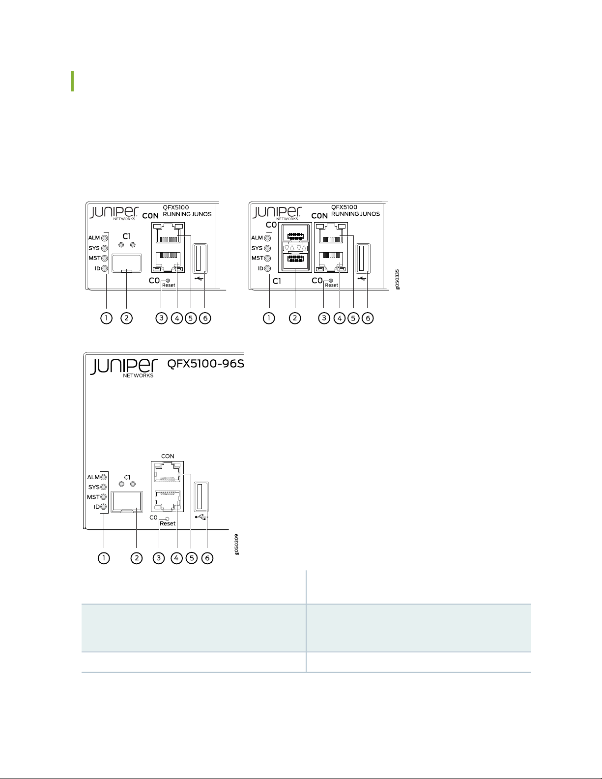
Management Port LEDs on a QFX5100 Device
The management ports (labeled C0 for 10/100/1000 Base-T and C1 for 10/100/1000 Base-T and SFP
1000 Base-X connections) on a QFX5100 switch have two LEDs that indicate link status and link activity
(see Figure 24 on page 59). The left LED indicates status; the right LED indicates link/activity.
Figure 24: Management Port LEDs on a QFX5100 Switch
59
Status LEDs
Cage (socket for either 10/100/1000 Base-T RJ45
SFP or 1GbE fiber SFP)
4—1— em0–RJ-45 (10/100/1000 Base-T) management
Ethernet port (C0)
5—2— RJ-45 console port (CON)em1–SFP management Ethernet port (C1)
6—3— USB portReset button, see caution statement below
Page 60

CAUTION: Do not use the Reset button to restart the power sequence unless under
the direction of Juniper Networks Technical Assistance Center (JTAC).
Table 13 on page 60 describes the management port LEDs.
Table 13: Management Port LEDs on a QFX5100 Switch
60
DescriptionStateColorLED
OffUnlitLink/Activity
No link is established, there is a fault, or the link is
down.
A link is established, but there is no link activity.On steadilyGreen
A link is established, and there is link activity.Blinking or flickering
Either the port speed is 10 M or the link is down.OffUnlitStatus
The port speed is 1000 M.On steadilyGreen
The port speed is 100 M.On steadilyAmber
Chassis Status LEDs on a QFX5100 Device
The QFX5100 switch series has four status LEDs on the FRU side of the chassis, next to the management
ports (see Figure 25 on page 61).
Page 61

Figure 25: Chassis Status LEDs on a QFX5100 Switch
61
Status LEDs
Cage (socket for either 10/100/1000 Base-T RJ45
SFP or 1GbE fiber SFP)
4—1— em0–RJ-45 (10/100/1000 Base-T) management
Ethernet port (C0)
5—2— RJ-45 console port (CON )em1–SFP management Ethernet port (C1)
6—3— USB portReset button, see caution statement below
CAUTION: Do not use the Reset button to restart the power sequence unless under
the direction of Juniper Networks Technical Assistance Center (JTAC).
Table 14 on page 62 describes the chassis status LEDs on a QFX5100 switch, their colors and states, and
the status they indicate. You can view the colors of the three LEDs remotely through the CLI by issuing
the operational mode command show chassis led.
Page 62

Table 14: Chassis Status LEDs on a QFX5100 Switch
62
DescriptionStateColorName
OffUnlitALM–Alarm or beacon
On steadilyRed
On steadilyAmber
The switch is halted or there is no
alarm.
A major hardware fault has occurred,
such as a temperature alarm or power
failure, and the switch has halted.
Power off the QFX5100 switch by
setting the AC power source outlet to
the OFF (O) position, or unplugging the
AC power cords. Correct any voltage
or site temperature issues, and allow
the switch to cool down. Power on the
QFX5100 switch and monitor the
power supply and fan LEDs to help
determine where the error is occurring.
A minor alarm has occurred, such as a
software error. Power off the
QFX5100 switch by setting the AC
power source outlet to the OFF (O)
position, or unplugging the AC power
cords. Power on the QFX5100 switch
and monitor the status LEDs to ensure
that Junos OS boots properly.
The switch is powered off or halted.OffUnlitSYS–System
On steadilyGreen
BlinkingGreen
Junos OS for QFX Series is loaded on
the switch.
The switch is participating as:
A member in a QFX Virtual Chassis
•
A leaf device in a Virtual Chassis
•
Fabric (VCF)
A spine device in a VCF
•
A Routing Engine Primary in a VCF
•
A Routing Engine Backup in a VCF
•
Page 63

Table 14: Chassis Status LEDs on a QFX5100 Switch (continued)
63
DescriptionStateColorName
Virtual Chassis or Routing
Engine Primary in a VCF
OffUnlitMST–Primary in a QFX
On steadilyGreen
BlinkingGreen
OffUnlitID–Identification
BlinkingBlue
The switch is a linecard member in a
QFX Virtual Chassis.
The switch is one of the following:
A standalone switch
•
In the primary role in a QFX Virtual
•
Chassis
Is the routing engine primary in a
•
VCF
The switch is the backup primary in a
QFX Virtual Chassis or the backup
routing engine in a VCF.
The beacon feature is not enabled on
the switch. This feature is enabled
using the request chassis beacon
command.
The beacon feature is enabled on the
switch. This feature is enabled using
the request chassis beacon command.
SEE ALSO
show chassis alarms
request chassis beacon
RELATED DOCUMENTATION
USB Port Specifications for the QFX Series | 111
Installing and Removing QFX5100 Device Hardware Components | 180
Connect a Device to a Network for Out-of-Band Management | 124
Page 64
QFX5100 Power System
IN THIS SECTION
AC Power Supply for a QFX5100 Device | 64
AC Power Specifications for a QFX5100 Device | 67
AC Power Cord Specifications for a QFX5100 Device | 68
AC Power Supply LEDs on a QFX5100 Device | 69
DC Power Supply in a QFX5100 Device | 70
DC Power Specifications for a QFX5100 Device | 72
DC Power Supply LEDs on a QFX5100 Device | 73
64
AC Power Supply for a QFX5100 Device
The two power supplies in QFX5100 switches are hot-removable and hot-insertable field-replaceable
units (FRUs). The power supplies are installed in the switch at the factory. You can install replacement
power supplies from the management panel without powering off the switch or disrupting the switching
function.
The AC power supply in 1 U QFX5100 switches is 650 W; the AC power supply in the 2 U, QFX5100-96S
switch, is 850 W. Both power supplies look identical. Be sure to use the correct power supply for your
chassis product SKU (see Table 15 on page 66).
CAUTION: Do not mix power supplies with different airflow or different wattage. The
system raises an alarm when a power supply having a different airflow or wattage is
inserted into the chassis.
See Figure 26 on page 65 for an example of the 1 U design and Figure 27 on page 65 for an example of
the 2 U power supply.
Page 65

Figure 26: 1 U AC Power Supply in QFX5100 Switches
g050255
1 2
3
4
3—1— AC appliance inletHandle
4—2— Ejector leverSecurity latch
Figure 27: 2 U AC Power Supply in a QFX5100-96S Switch
65
The power supply provides FRU-to-port or port-to-FRU airflow depending on the product SKU you
purchase. On legacy switches, or switches with an LCD, this airflow is called back-to-front and front-to-back.
The power supplies have color-coded handles with a fan icon. See Figure 28 on page 66 for an example
of the power supply. A power supply with a blue handle denotes FRU-to-port airflow; a power supply with
a gold-colored handle denotes port-to-FRU airflow.
Page 66

Figure 28: Power Supply Handle Detail
1—Fan icon on handle
CAUTION: Verify that the airflow direction on the power supply handle matches the
direction of airflow in the chassis. Ensure that each power supply you install in the
chassis has the same airflow direction. If you install power supplies with two different
airflow directions, Junos OS raises an alarm. If you need to convert the airflow pattern
on a chassis, you must change out all the fans and power supplies at one time to use
the new direction.
66
Table 15 on page 66 shows the different power supplies and their direction of airflow.
Table 15: Airflow Direction in QFX5100 AC Power Supplies
QFX5100
Product SKUs
QFX5100-48S
QFX5100-48SH
QFX5100-48T
QFX5100-48TH
650 WQFX5100-24Q
QFXC01-PWRACI-650A
(older version)
JPSU-850W-AC-AFI850 WQFX5100-96S
Direction of
AirflowProduct NumberWattage
Color of Power
Supply Handle
Juniper Azure BlueFRU-to-portJPSU-650W-AC-AFI
Page 67

Table 15: Airflow Direction in QFX5100 AC Power Supplies (continued)
67
QFX5100
Product SKUs
QFX5100-48S
QFX5100-48SH
QFX5100-48T
QFX5100-48TH
Direction of
AirflowProduct NumberWattage
650 WQFX5100-24Q
QFXC01-PWRACO-650A
(older version)
JPSU-850W-AC-AFO850 WQFX5100-96S
Color of Power
Supply Handle
Juniper GoldPort-to-FRUJPSU-650W-AC-AFO
To avoid electrical injury, carefully follow instructions in “Connecting AC Power to a QFX5100 Device”
on page 139.
AC Power Specifications for a QFX5100 Device
Table 16 on page 67 describes the AC power specifications for a QFX5100 device.
Table 16: AC Power Specifications for a QFX5100 Device
Item
AC input voltage
AC input line frequency
AC input current rating
Typical power consumption
230 WQFX5100-24Q
230 WQFX5100-48S and QFX5100-48SH
322 WQFX5100-48T and QFX5100-48TH
315 WQFX5100-96S
Maximum power consumption
Page 68

Table 16: AC Power Specifications for a QFX5100 Device (continued)
Item
365 WQFX5100-24Q
365 WQFX5100-48S and QFX5100-48SH
395 WQFX5100-48T and QFX5100-48TH
470 WQFX5100-96S
AC Power Cord Specifications for a QFX5100 Device
Detachable AC power cords are shipped with the chassis, if you include them as part of your order. The
coupler is type C13 as described by International Electrotechnical Commission (IEC) standard 60320. The
plug end of the power cord fits into the power source outlet that is standard for your geographical location.
68
CAUTION: The AC power cord for the device is intended for use with that chassis
only and not for any other use.
NOTE: In North America, AC power cords must not exceed 4.5 meters (approximately 14.75 feet)
in length, to comply with National Electrical Code (NEC) Sections 400-8 (NFPA 75, 5-2.2) and
210-52 and Canadian Electrical Code (CEC) Section 4-010(3). The cords that can be ordered for
the QFX5100 devices are in compliance.
Table 17 on page 68 lists AC power cord specifications provided for each country or region.
Table 17: AC Power Cord Specifications
Plug StandardsElectrical SpecificationsCountry/Region
AS/NZ 3112-1993250 VAC, 10 A, 50 HzAustralia
250 VAC, 10 A, 50 HzChina
GB2099.1 1996 and GB1002 1996
(CH1-10P)
and United Kingdom)
CEE (7) VII250 VAC, 10 A, 50 HzEurope (except Italy, Switzerland,
Page 69

Table 17: AC Power Cord Specifications (continued)
g050008
AC OK
DC OK
Fault
Plug StandardsElectrical SpecificationsCountry/Region
CEI 23-16/VII250 VAC, 10 A, 50 HzItaly
JIS 8303125 VAC, 12 A, 50 Hz or 60 HzJapan
NEMA 5-15125 VAC, 13 A, 60 HzNorth America
KSC 8305250 VAC, 10 A, 60 HzSouth Korea
SEV 1011 SEV 6534/2250 VAC, 10 A, 50 HzSwitzerland
BS 1363A250 VAC, 10 A, 50 HzUnited Kingdom
Figure 29 on page 69 illustrates the plug on the power cord for some of the countries or regions listed in
Table 17 on page 68.
69
Figure 29: AC Plug Types
AC Power Supply LEDs on a QFX5100 Device
Figure 30 on page 69 shows the location of the LEDs on the power supply.
Figure 30: AC Power Supply LEDs on a QFX5100 Switch
Table 18 on page 70 describes the LEDs on the AC power supplies.
Page 70

Table 18: AC Power Supply LEDs on a QFX5100 Switch
DescriptionStateColorLED
70
OffUnlitAC OK
OffUnlitDC OK
On steadilyAmberFault
The power supply is disconnected from power, or power is not
coming into the power supply.
Power is coming into the power supply.On steadilyGreen
The power supply is disconnected from power, or the power supply
is not sending out power correctly.
The power supply is sending out power correctly.On steadilyGreen
An error has been detected in the power supply. Replace the power
supply as soon as possible. To maintain proper airflow through the
chassis, leave the power supply installed in the chassis until you
are ready to replace it.
NOTE: If the AC OK LED and the DC OK LED are unlit, either the AC power cord is not installed
properly or the power supply fuse has failed. If the AC OK LED is lit and the DC OK LED is unlit,
the AC power supply is installed properly, but the power supply has an internal failure.
DC Power Supply in a QFX5100 Device
The power supplies in QFX5100 devices (see Figure 31 on page 71) are hot-removable and hot-insertable
field-replaceable units (FRUs) that you can install in 1 U DC product SKUs of QFX5100 devices without
powering off the device or disrupting the switching function.
The DC power supply in 1 U product SKUs of QFX5100 is 650 W with dual feeds for power resiliency.
The DC power supply in the 2 U product SKU, QFX5100-96S, is 850 W with dual feeds for power resiliency.
Both power supplies have a similar design. See Figure 31 on page 71 for an example of the 1 U design and
Figure 32 on page 71 for an example of the 2 U power supply.
Page 71

Figure 31: DC Power Supply in QFX5100 Devices
3—1— Ejector leverTerminal block
4—2— HandleESD grounding point
To supply sufficient power for 1 U models, terminate the DC input wiring on a facility DC source that is
capable of supplying a minimum of 7 A at –48 VDC.
71
Figure 32: DC Power Supply for QFX5100-96S Devices
3—1— Ejector leverTerminal block
4—2— HandleESD grounding point
NOTE: The DC power supply in the switch has four terminals labeled V-, V-, V+, and V+ (see
Figure 33 on page 72) for connecting DC power source cables labeled positive (+) and negative (–).
Page 72

Figure 33: DC Power Supply Faceplate in QFX5100 Devices
5
5—1— ESD grounding pointShunt negative input terminals (-48V)
72
6—2— Fault LEDShunt positive input terminals (+RTN)
7—3— Output LEDTerminal block
8—4— Input LEDEjector lever
To avoid electrical injury, carefully follow instructions in “Install and Remove QFX5100 Power Supplies”
on page 157.
DC Power Specifications for a QFX5100 Device
Table 19 on page 73 describes the DC power specifications for DC product SKUs of the QFX5100 device.
Page 73

Table 19: DC Power Specifications for a QFX5100 Device
73
SpecificationsProduct SKUsItem
DC input voltage
DC input current
rating
Typical power
consumption
QFX5100-24Q
QFX5100-48S
QFX5100-48T
QFX5100-96S
QFX5100-48S
QFX5100-48T
QFX5100-96S
QFX5100-48T
QFX5100-24Q
Rated operating voltage: –48 VDC to -60
•
VDC
Operating voltage range: -40 VDC through
•
–72 VDC
Rated operating voltage: VDC -48 VDC to
•
-60 VDC
Operating voltage range: –40 VDC through
•
-72 VDC
10 A maximumQFX5100-24Q
300 WQFX5100-48S
315 WQFX5100-96S
Maximum power
consumption
QFX5100-48S
QFX5100-48T
385 WQFX5100-24Q
470 WQFX5100-96S
DC Power Supply LEDs on a QFX5100 Device
Figure 34 on page 74 shows the location of the LEDs on the DC power supply.
Page 74

Figure 34: DC Power Supply Faceplate on a QFX5100 Switch
3—1— Fault LEDInput LED
2—Output LED
CAUTION: The V+ terminals are shunted internally together, as are the V- terminals.
The same polarity terminal can be wired together from the same source to provide an
additional current path in a higher power chassis. Do not connect the terminals to
different sources.
74
Table 20 on page 74 describes the LEDs on the DC power supplies.
Table 20: DC Power Supply LEDs on a QFX5100 Switch
OffUnlitInput
OffUnlitOutput
On steadilyGreen
DescriptionStateColorName
The power supply is disconnected from
power, or power is not coming into the power
supply.
Power is coming into the power supply.On steadilyGreen
The power supply is disconnected from
power, or the power supply is not sending out
power correctly.
The power supply is sending out power
correctly.
Page 75

Table 20: DC Power Supply LEDs on a QFX5100 Switch (continued)
DescriptionStateColorName
75
On steadilyAmberFault
RELATED DOCUMENTATION
Connect the QFX5100 to Power | 137
Prevention of Electrostatic Discharge Damage | 242
QFX5100 Cooling System
An error has been detected in the power
supply. Replace the power supply as soon as
possible. To maintain proper airflow through
the chassis, leave the power supply installed
in the chassis until you are ready to replace
it.
IN THIS SECTION
Cooling System and Airflow in a QFX5100 Device | 75
Fan Module LED on a QFX5100 Device | 82
Clearance Requirements for Airflow and Hardware Maintenance for a QFX5100 Device | 83
Cooling System and Airflow in a QFX5100 Device
IN THIS SECTION
Fan Modules | 76
Do Not Install Components with Different Airflow or Wattage in the Switch | 80
Fan Module Status | 81
Page 76

The cooling system in an QFX5100 device consists of fan modules and a single fan in each power supply.
The number of fan modules vary depending whether the size of the switch is 1 U or 2 U high. All switches
can be set up to work in one of two airflow directions:
Airflow In–Air comes into the switch through the vents in the field-replaceable units (FRUs)
•
Airflow Out–Air comes into the switch through the vents in the port panel.
•
CAUTION: Airflow In and Airflow Out fans and power supplies cannot be mixed in
the same chassis.
Fan Modules
The fan modules in QFX5100 devices are hot-insertable and hot-removable field-replaceable units (FRUs).
These fan modules are designed for one of the two available airflow directions (Airflow In or Airflow Out).
Some fan modules are also color-coded for the airflow direction as well. The fan modules are installed in
the fan module slots on the management panel of the switch next to the power supplies.
76
Both the 1 U and 2 U versions of QFX5100 fan modules have a similar design with different dimensions.
The 1 U QFX5100 devices have 5 fan modules numbered 0 through 4 from left to right, where the 2 U,
QFX5100-96S device, has 3 fan modules numbered 0 through 2. On all QFX5100 devices, each fan module
slot has a fan icon next to it.
Figure 35 on page 76 shows the 1 U fan module and Figure 36 on page 77 shows the 2 U fan module.
Figure 35: 1 U Fan Module Used in QFX5100 Switches
Page 77

Figure 36: 2 U Fan Module Used in QFX5100-96S Switches
g050311
You remove and replace a fan module from the FRU end of the chassis. The switch continues to operate
for a limited period of time (30 seconds) during the replacement of the fan module without thermal
shutdown.
77
NOTE: All fan modules must be installed for optimal operation of the switch.
The fan modules are available in two product SKUs that have different airflow directions—FRU-to-port
airflow, indicated on some units by the azure blue color or a label. FRU-to-port airflow versions of the fan
module that have labels are marked AIR IN . Likewise, port-to-FRU airflow is indicated by either a gold
color or the label AIR OUT . On legacy switches or switches with LCDs, this airflow is also called
front-to-back and back-to-front. Table 21 on page 78 lists the available fan module product SKUs and the
direction of airflow in them:
Page 78

Table 21: Fan Modules in QFX5100 Switches
Label
on the
Fan
ModuleAirflow DiagramProduct SKUsFan Module
Color
of Fan
Module
Direction of
Airflow in the
Fan Module
78
Power
Supplies
QFX5100-FAN-AFI
QFX5100-FAN-AFO
QFX5100-48S
QFX5100-48SH
QFX5100-48T
QFX5100-48TH
QFX5100-48S
QFX5100-48SH
QFX5100-48T
QFX5100-48TH
AIR INFigure37 on page 79QFX5100-24Q
Figure 38 on page 79QFX5100-96SQFX5100-96S-FANAFI
Figure 39 on page 80QFX5100-24Q
Figure 40 on page 80QFX5100-96SQFX5100-96S-FANAFO
AIR
OUT
Juniper
Azure
Blue
Juniper
Gold
FRU-to-port,
that is, air
comes in from
the end of the
switch with the
fans; air
exhausts from
the switch end
with ports (also
known as
back-to-front
airflow).
Port-to-FRU,
that is, air
comes in
through vents
on the end with
ports; air
exhausts out
the end with
the fans (also
known as
front-to-back
airflow).
You must
install only
power
supplies
that have
AIR IN
labels in
switches
in which
the fan
modules
have AIR
IN labels.
You must
install only
power
supplies
that have
AIR OUT
labels in
switches
in which
the fan
modules
have AIR
OUT
labels.
In data center deployments, position the switch in such a manner that the AIR IN labels on switch
components are next to the cold aisle, and AIR OUT labels on switch components are next to the hot
aisle.
Page 79

Figure 37: Air In Airflow Through 1 U QFX5100 Switch Chassis
79
Figure 38: Air In Airflow Through 2 U QFX5100 Switch Chassis
Page 80

Figure 39: Air Out Airflow Through 1 U QFX5100 Switch Chassis
80
Figure 40: Air Out Airflow Through 2 U QFX5100 Switch Chassis
Do Not Install Components with Different Airflow or Wattage in the Switch
Do not mix power supplies with different airflow. If the power supplies are color-coded, ensure they are
either all azure blue for airflow in models or all gold for airflow out models. If the power supplies are not
color-coded but have a label, ensure that the chassis is either using all airflow in ( AFI ) or all airflow out
(AFO). Likewise, ensure that all fan modules have the same airflow and match the airflow of the power
supplies. Fan modules are also either color-coded azure blue for airflow in or gold for airflow out. If the
fan module has a label instead of being color-coded, ensure that labels (AIR IN and AIR OUT ) are not
mixed. If the fan modules have AIR IN labels, the power supplies must also have AIR IN labels; if the fan
modules have AIR OUT labels, the power supplies must also have AIR OUT labels.
Page 81

Mixing components with different airflows in the same chassis hampers the performance of the cooling
system of the switch and leads to overheating of the chassis.
CAUTION: The system raises an alarm if a fan module fails or if the ambient
temperature inside the chassis rises above the acceptable range. If the temperature
inside the chassis rises above the threshold temperature, the system shuts down
automatically.
Do not mix fan modules with different wattage. Only use the replacement fan modules that are designed
for use with your product number. See Table 21 on page 78 for the correct part number for your QFX5100
device.
CAUTION: Do not mix AC and DC power supplies in the same chassis.
81
However if you need to convert a QFX5100 device to have a different airflow, you can change the airflow
pattern. To convert an AIR IN product SKU to an AIR OUT product SKU or an AIR OUT product SKU to
a AIR IN product SKU, you must replace all of the fans and power supplies at one time to use the new
direction. The system raises an alarm when the system is converted, which is normal.
Fan Module Status
You can check the status of fan modules through the show system alarms command or by looking at the
LEDs next to each fan module.
Each switch has a Status LED (labeled ST) for each fan module on the left side of the corresponding fan
module slot. It indicates the status of all the fan modules. Table 22 on page 81 describes the Status LED
on the fan module in a QFX5100 device.
Table 22: Fan Module LED
DescriptionLED State
Solid Green
The individual fan module is present. After the hardware senses the fan module, software
ensures the airflow is consistent with the other fan modules and that it is functioning
correctly.
Blinking Amber
Indicates one of the following:
The fan module is not present.
•
The fan module is not functioning normally.
•
Page 82

Under normal operating conditions, the fan modules operate at a moderate speed. Temperature sensors
1
in the chassis monitor the temperature within the chassis.
The system raises an alarm if a fan module fails or if the ambient temperature inside the chassis rises above
the acceptable range. If the temperature inside the chassis rises above the threshold temperature, the
system shuts down automatically.
SEE ALSO
Field-Replaceable Units in a QFX5100 Device | 32
Prevention of Electrostatic Discharge Damage | 242
QFX5100 Device Hardware Overview | 19
Installing a Fan Module in a QFX5100 Device | 154
Removing a Fan Module from a QFX5100 Device | 155
82
Fan Module LED on a QFX5100 Device
Figure 41 on page 82 shows the location of the LED next to the fan module.
Figure 41: Fan Module LED in a QFX5100 Switch
1—Fan LED
Table 23 on page 83 describes the function of the fan tray LED.
Page 83

Table 23: Fan Tray LED in a QFX5100 Switch
FRUs
Ports
Mounting bracket
17.36"
44.1 cm
20.48"
(52.02 cm)
Clearance required
for maintenance
Clearance required
for maintenance
g050277
19"
(48.2 cm)
24 " ( 6 0 .9 cm) 24 " ( 6 0 .9 cm)
83
DescriptionStateColorName
On steadilyGreenFan
The fan module is operating normally. The
system has verified that the module is
engaged, that the airflow is in the correct
direction, and that the fan is operating
correctly.
BlinkingAmber
An error has been detected in the fan
module. Replace the fan module as soon
as possible. Either the fan has failed or it
is seated incorrectly. To maintain proper
airflow through the chassis, leave the fan
module installed in the chassis until you
are ready to replace it.
Clearance Requirements for Airflow and Hardware Maintenance for a QFX5100 Device
When planning the site for installing a QFX5100 device, you must allow sufficient clearance around the
installed chassis (see Figure 42 on page 83).
Figure 42: Clearance Requirements for Airflow and Hardware Maintenance for a QFX5100 Device
For the cooling system to function properly, the airflow around the chassis must be unrestricted. See
•
“Cooling System and Airflow in a QFX5100 Device” on page 75 for more information about the airflow
through the chassis.
Page 84

If you are mounting a QFX5100 device in a rack or cabinet with other equipment, ensure that the exhaust
•
from other equipment does not blow into the intake vents of the chassis.
Leave at least 24 in. (61 cm) both in front of and behind the QFX5100 device. For service personnel to
•
remove and install hardware components, you must leave adequate space at the front and back of the
switch. NEBS GR-63 recommends that you allow at least 30 in. (76.2 cm) in front of the rack or cabinet
and 24 in. (61 cm) behind the rack or cabinet.
RELATED DOCUMENTATION
Install and Remove QFX5100 Fan Modules | 154
General Site Guidelines | 90
Rack-Mounting and Cabinet-Mounting Warnings | 220
84
Page 85

2
CHAPTER
Site Planning, Preparation, and
Specifications
Site Preparation Checklist for a QFX5100 Device | 86
QFX5100 Site Guidelines and Requirements | 88
Plan a Virtual Chassis Fabric Deployment | 95
QFX5100 Network Cable and Transceiver Planning | 98
QFX5100 Cable and Pinout Specifications | 107
Page 86

Site Preparation Checklist for a QFX5100 Device
The checklist in Table 24 on page 86 summarizes the tasks you need to perform when preparing a site for
QFX5100 deviceinstallation.
Table 24: Site Preparation Checklist
DatePerformed ByFor More InformationItem or Task
Architecture
86
Determine whether the QFX5100 device
will operate:
standalone
•
as a member in a Virtual Chassis
•
as a spine or leaf in a Virtual Chassis
•
Fabric (VCF)
as a node in a QFabric
•
Environment
Verify that environmental factors such
as temperature and humidity do not
exceed switch tolerances.
Power
Measure the distance between external
power sources and switch installation
site.
Calculate the power consumption and
requirements.
Plan a Virtual Chassis Fabric
•
Deployment on page 95
Planning a QFX3000-G QFabric
•
System Deployment
Planning a QFX3000-M QFabric
•
System Deployment
“Environmental Requirements and
Specifications for a QFX5100 Device”
on page 88
“AC Power Specifications for a
QFX5100 Device” on page 67
Rack or Cabinet
Verify that your rack or cabinet meets
the minimum requirements for the
installation of the switch.
“Rack Requirements for a QFX5100
Device” on page 92
“Cabinet Requirements for a
QFX5100 Device” on page 94
Page 87

Table 24: Site Preparation Checklist (continued)
87
DatePerformed ByFor More InformationItem or Task
Plan rack or cabinet location, including
required space clearances.
Secure the rack or cabinet to the floor
and building structure.
Cables
Acquire cables and connectors:
Determine the number of cables
•
needed based on your planned
configuration.
Review the maximum distance allowed
•
for each cable. Choose the length of
cable based on the distance between
the hardware components being
connected.
“Clearance Requirements for Airflow
and Hardware Maintenance for a
QFX5100 Device” on page 83
Port Panel of a QFX5100-24Q
•
Device on page 34
Port Panel of a QFX5100-24Q-AA
•
Device on page 39
Port Panel of QFX5100-48S and
•
QFX5100-48SH Devices on
page 39
Port Panel of QFX5100-48T and
•
QFX5100-48TH Devices on
page 42
Port Panel of a QFX5100-96S
•
Device on page 44
Plan the cable routing and management.
RELATED DOCUMENTATION
General Safety Guidelines and Warnings | 208
QFX5100 Standalone Installation Overview | 114
Page 88

QFX5100 Site Guidelines and Requirements
IN THIS SECTION
Environmental Requirements and Specifications for a QFX5100 Device | 88
General Site Guidelines | 90
Site Electrical Wiring Guidelines | 90
Grounding Cable and Lug Specifications for a QFX5100 Device | 91
Rack Requirements for a QFX5100 Device | 92
Cabinet Requirements for a QFX5100 Device | 94
88
Environmental Requirements and Specifications for a QFX5100 Device
The switch must be installed in a rack or cabinet. It must be housed in a dry, clean, well-ventilated, and
temperature-controlled environment.
Follow these environmental guidelines:
The site must be as dust-free as possible, because dust can clog air intake vents and filters, reducing the
•
efficiency of the switch cooling system.
Maintain ambient airflow for normal switch operation. If the airflow is blocked or restricted, or if the
•
intake air is too warm, the switch might overheat, leading to the switch temperature monitor shutting
down the device to protect the hardware components.
Table 25 on page 88 provides the required environmental conditions for normal switch operation.
Table 25: QFX5100 Switch Environmental Tolerances
ToleranceDescription
No performance degradation to 6,562 feet (2000 meters)Altitude
Page 89

Table 25: QFX5100 Switch Environmental Tolerances (continued)
ToleranceDescription
89
Relative humidity
Temperature
Seismic
Normal operation ensured in relative humidity range of 5% through 90%,
noncondensing
Short-term operation ensured in relative humidity range of 5% through
•
93%, noncondensing
NOTE: As defined in NEBS GR-63-CORE, Issue 3, short-term events can
be up to 96 hours in duration but not more than 15 days per year.
Normal operation ensured in temperature range of 32° F through 104° F
•
(0° C through 40° C)
NOTE: Customers with QFX5100-48T switches should ensure the room
temperature does not exceed a 2° C increase or decrease per minute.
Nonoperating storage temperature in shipping container: –40° F through
•
158° F (–40° C through 70° C)
Designed to comply with Zone 4 earthquake requirements per NEBS
GR-63-CORE, Issue 3.
NOTE: Install QFX Series devices only in restricted areas, such as dedicated equipment rooms
and equipment closets, in accordance with Articles 110-16, 110-17, and 110-18 of the National
Electrical Code, ANSI/NFPA 70.
SEE ALSO
Clearance Requirements for Airflow and Hardware Maintenance for a QFX5100 Device | 83
QFX5100 Standalone Installation Overview | 114
Page 90

General Site Guidelines
Efficient device operation requires proper site planning and maintenance and proper layout of the equipment,
rack or cabinet, and wiring closet.
To plan and create an acceptable operating environment for your device and prevent environmentally
caused equipment failures:
Keep the area around the chassis free from dust and conductive material, such as metal flakes.
•
Follow prescribed airflow guidelines to ensure that the cooling system functions properly and that
•
exhaust from other equipment does not blow into the intake vents of the device.
Follow the prescribed electrostatic discharge (ESD) prevention procedures to prevent damaging the
•
equipment. Static discharge can cause components to fail completely or intermittently over time.
Install the device in a secure area, so that only authorized personnel can access the device.
•
90
Site Electrical Wiring Guidelines
Table 26 on page 90 describes the factors you must consider while planning the electrical wiring at your
site.
WARNING: You must provide a properly grounded and shielded environment and use
electrical surge-suppression devices.
Avertissement Vous devez établir un environnement protégé et convenablement mis
à la terre et utiliser des dispositifs de parasurtension.
Table 26: Site Electrical Wiring Guidelines
Site Wiring
Factor
Signaling
limitations
Guidelines
If your site experiences any of the following problems, consult experts in electrical surge suppression
and shielding:
Improperly installed wires cause radio frequency interference (RFI).
•
Damage from lightning strikes occurs when wires exceed recommended distances or pass between
•
buildings.
Electromagnetic pulses (EMPs) caused by lightning damage unshielded conductors and electronic
•
devices.
Page 91

Table 26: Site Electrical Wiring Guidelines (continued)
Site Wiring
Factor
Guidelines
91
Radio
frequency
interference
Electromagnetic
compatibility
To reduce or eliminate RFI from your site wiring, do the following:
Use a twisted-pair cable with a good distribution of grounding conductors.
•
If you must exceed the recommended distances, use a high-quality twisted-pair cable with one
•
ground conductor for each data signal when applicable.
If your site is susceptible to problems with electromagnetic compatibility (EMC), particularly from
lightning or radio transmitters, seek expert advice.
Some of the problems caused by strong sources of electromagnetic interference (EMI) are:
Destruction of the signal drivers and receivers in the device
•
Electrical hazards as a result of power surges conducted over the lines into the equipment
•
Grounding Cable and Lug Specifications for a QFX5100 Device
For installations that require a separate grounding conductor to the chassis, the switch must be adequately
grounded before power is connected to ensure proper operation and to meet safety and electromagnetic
interference (EMI) requirements. To ground a QFX5100 device, connect a grounding cable to earth ground
and then attach it to the chassis grounding points.
WARNING: The switch is pluggable type A equipment installed in a restricted-access
location. It has a separate protective earthing terminal provided on the chassis in
addition to the grounding pin of the power supply cord. This separate protective
earthing terminal must be permanently connected to earth ground for installations
that require a separate grounding conductor to the chassis.
WARNING: To comply with GR-1089 requirements, all intra-building copper cabling
used for SFP+ and QSFP+ ports must be shielded and grounded at both ends.
Page 92

CAUTION: Before switch installation begins, a licensed electrician must attach a cable
lug to the grounding cables that you supply. See “Connecting Earth Ground to a
QFX5100 Device” on page 138. A cable with an incorrectly attached lug can damage
the switch.
Before connecting the switch to earth ground, review the following information:
A protective earthing terminal bracket is provided in the accessory kit for connecting the switch to earth
•
ground. This L-shaped bracket attaches to the side of the QFX5100 chassis through the mounting
bracket, providing a protective earthing terminal for the switch.
The grounding lug required is a Panduit LCD10-10A-L or equivalent (not provided).. The grounding lug
•
should accommodates 14–10 AWG (2–5.3 mm²) stranded wire.
The grounding cable that you provide for a QFX5100 device must be 14 AWG (2 mm²), minimum 60°
•
C wire, or as permitted by the local code.
92
Ensure you have two SAE 10-32 washers and screws to attach the cable and bracket (not provided).
•
SEE ALSO
QFX5100 Power System | 64
Connect the QFX5100 to Power | 137
Rack Requirements for a QFX5100 Device
All QFX5100 devices are designed to be installed on four-post racks. The QFX5100-96S device can also
be installed on two-post racks.
Rack requirements consist of:
Rack type
•
Mounting bracket hole spacing
•
Rack size and strength
•
Table 27 on page 93 provides the rack requirements and specifications for the QFX5100 device.
Page 93

Table 27: Rack Requirements for the QFX5100 Device
GuidelinesRack Requirement
93
Rack type (all product
SKUs)
Rack type (QFX5100-96S
only)
Mounting bracket hole
spacing (all product SKUs)
Rack size and strength (all
product SKUs)
Use a four-post rack that provides bracket holes or hole patterns spaced at 1 U (1.75 in.
or 4.45 cm) increments and that meets the size and strength requirements to support the
weight.
A U is the standard rack unit defined in Cabinets, Racks, Panels, and Associated Equipment
(document number EIA-310–D) published by the Electronics Industry Association.
Use a two-post or four-post rack that provides bracket holes or hole patterns spaced at
1 U (1.75 in. or 4.45 cm) increments and that meets the size and strength requirements
to support the weight.
The holes in the mounting brackets are spaced at 1 U (1.75 in. or 4.45 cm), so that the
switch can be mounted in any rack that provides holes spaced at that distance.
Ensure that the rack complies with the standards for a 19-in. or 23-in. rack as defined
•
in Cabinets, Racks, Panels, and Associated Equipment (document number EIA-310–D)
published by the Electronics Industry Association.
A 600-mm rack as defined in the four-part Equipment Engineering (EE); European
•
telecommunications standard for equipment practice (document numbers ETS 300 119-1
through 119-4) published by the European Telecommunications Standards Institute.
The horizontal spacing between the rails in a rack that complies with this standard is
usually wider than the device's mounting brackets, which measure 19 in. (48.26 cm)
from outer edge to outer edge. Use approved wing devices to narrow the opening
between the rails as required.
Ensure that the rack rails are spaced widely enough to accommodate the switch chassis’
•
external dimensions. The outer edges of the front-mounting brackets extend the width
to 28.5 in. (72.4 cm) to 31.5 in. (80 cm).
For four-post installations, the front and rear rack rails must be spaced between 28.5
•
in. (72.4 cm) to 31.5 in. (80 cm) front-to-back.
The rack must be strong enough to support the weight of the switch.
•
Ensure that the spacing of rails and adjacent racks allows for proper clearance around
•
the switch and rack.
Rack connection to
building structure
SEE ALSO
Secure the rack to the building structure.
•
If earthquakes are a possibility in your geographical area, secure the rack to the floor.
•
Secure the rack to the ceiling brackets as well as wall or floor brackets for maximum
•
stability.
Page 94

Chassis Physical Specifications for a QFX5100 Device | 34
Rack-Mounting and Cabinet-Mounting Warnings | 220
Clearance Requirements for Airflow and Hardware Maintenance for a QFX5100 Device | 83
Mount a QFX5100 Device in a Rack or Cabinet | 120
Cabinet Requirements for a QFX5100 Device
You can mount the QFX5100 device in an enclosure or cabinet that contains a four-post 19-in. open rack
as defined in Cabinets, Racks, Panels, and Associated Equipment (document number EIA-310-D) published
by the Electronics Industry Association.
Cabinet requirements consist of:
Cabinet size and clearance
•
Cabinet airflow requirements
•
94
Table 28 on page 94 provides the cabinet requirements and specifications for the QFX5100 device.
Table 28: Cabinet Requirements for the QFX5100 Device
GuidelinesCabinet Requirement
Cabinet size and clearance
The minimum cabinet size for accommodating a QFX5100 device is 36 in.
(91.4 cm) deep. Large cabinets improve airflow and reduce the chance of
overheating.
Page 95

Table 28: Cabinet Requirements for the QFX5100 Device (continued)
GuidelinesCabinet Requirement
95
Cabinet airflow requirements
When you mount the switch in a cabinet, ensure that ventilation through the
cabinet is sufficient to prevent overheating.
Ensure that the cool air supply you provide through the cabinet adequately
•
dissipates the thermal output of the switch (or switches).
Ensure that the cabinet allows the chassis hot exhaust air to exit the cabinet
•
without recirculating into the switch. An open cabinet (without a top or
doors) that employs hot air exhaust extraction from the top allows the best
airflow through the chassis. If the cabinet contains a top or doors,
perforations in these elements assist with removing the hot air exhaust.
The QFX5100 device fans exhaust hot air either through the vents on the
•
port panel or through the fans and power supplies. Install the switch in the
cabinet in a way that maximizes the open space on the FRU side of the
chassis. This maximizes the clearance for critical airflow.
Route and dress all cables to minimize the blockage of airflow to and from
•
the chassis.
Ensure that the spacing of rails and adjacent cabinets allows for the proper
•
clearance around the switch and cabinet.
RELATED DOCUMENTATION
Rack-Mounting and Cabinet-Mounting Warnings | 220
Clearance Requirements for Airflow and Hardware Maintenance for a QFX5100 Device | 83
Mount a QFX5100 Device in a Rack or Cabinet | 120
Plan a Virtual Chassis Fabric Deployment
A Virtual Chassis Fabric (VCF) architecture supports up to 20 interconnected devices that are managed
as a logical single device. Supported platforms vary depending on the QFX Series switch chosen for the
spine. See Understanding Virtual Chassis Fabric Components and Virtual Chassis Fabric Hardware Overview
for supported configurations. Although the architecture has a powerful auto-provisioning option, which
allows you to plug and play the devices, careful planning of the deployment can avoid unexpected results.
For example, if you perform any configuration level commands on one of the devices (including assigning
IP addresses or host names) you no longer can use auto-provisioning.
Page 96

Use the following checklist to plan your deployment:
Table 29: Deployment Checklist
Components
96
DatePerformed ByFor More InformationItem or Task
Determine the number of devices
in the VCF and the role of each
device.
NOTE: A VCF is not constrained to
a single building; the limits for the
optic cable are the only
consideration.
Environment
Evaluate the provisioning options
and determine the configuration
method that applies to your
deployment.
Power
Measure the distance between
external power sources and switch
installation site.
Understanding Virtual Chassis Fabric
Components
Understanding Virtual Chassis Fabric
Configuration
Calculate the power consumption
and requirements.
Rack or Cabinet
QFX5110 AC Power Specifications
“AC Power Specifications for a QFX5100
Device” on page 67
AC Power Specifications for a QFX3600 or
QFX3600-I Device
AC Power Specifications for a QFX3500
Device
AC Power Supply Specifications for EX4300
Switches
Page 97

Table 29: Deployment Checklist (continued)
97
DatePerformed ByFor More InformationItem or Task
Verify that your rack or cabinet
meets the minimum requirements
for the installation of the switch.
Plan rack or cabinet location,
including required space clearances.
QFX5110 Rack Requirements
“Rack Requirements for a QFX5100
Device” on page 92
“Cabinet Requirements for a QFX5100
Device” on page 94
Rack Requirements for a QFX3600 or
QFX3600-I Device
Cabinet Requirements for a QFX3600 or
QFX3600-I Device
Rack Requirements for a QFX3500 Device
Cabinet Requirements for a QFX3500 Device
Rack Requirements for EX4300 Switches
Cabinet Requirements for EX4300 Switches
QFX5110 Clearance Requirements for Airflow
and Hardware Maintenance
Secure the rack or cabinet to the
floor and building structure.
Cables
“Clearance Requirements for Airflow and
Hardware Maintenance for a QFX5100
Device” on page 83
Clearance Requirements for Airflow and
Hardware Maintenance for a QFX3600 or
QFX3600-I Device
Clearance Requirements for Airflow and
Hardware Maintenance for a QFX3500
Device
Clearance Requirements for Airflow and
Hardware Maintenance for EX4300 Switches
Page 98

Table 29: Deployment Checklist (continued)
98
DatePerformed ByFor More InformationItem or Task
Acquire cables and connectors:
Determine the number of cables
•
needed based on your planned
configuration.
Review the maximum distance
•
allowed for each cable. Choose
the length of cable based on the
distance between the hardware
components being connected.
Plan the cable routing and
management.
“Cable Specifications for QSFP+ and
QSFP28 Transceivers” on page 101
“Cable Specifications for Console and
Management Connections for the QFX
Series” on page 107
QFX5100 Network Cable and Transceiver Planning
IN THIS SECTION
Determining Interface Support for the QFX5100 Device | 98
Cable Specifications for QSFP+ and QSFP28 Transceivers | 101
Understanding QFX Series Fiber-Optic Cable Signal Loss, Attenuation, and Dispersion | 103
Calculating Power Budget and Power Margin for Fiber-Optic Cables | 104
Determining Interface Support for the QFX5100 Device
All product SKUs of the QFX5100 supply quad small form-factor pluggable plus (QSFP+) ports for use as
uplinks, as access ports, or as Virtual Chassis ports (VCPs). These 40 GbE ports support QSFP+ transceivers,
QSFP+ direct-attach copper (DAC) cables, and DAC breakout cables (DACBO). The QFX5100-48S has 6
QSFP+ ports; the QFX5100-96S has 8 QSFP+ ports; the QFX5100-24Q has 24 built-in QSFP+ ports that
can all be used as uplinks. The You can also add two QFX-EM-4Q expansion modules to the QFX5100-24Q
for additional QSFP+ uplink ports. Each QSFP+ port on a QFX5100-24Q can be configured to operate as
Page 99

10-Gigabit Ethernet interface by using a breakout cable or as a single 40-Gigabit Ethernet interface. See
Configuring the QSFP+ Port Type on QFX5100 Devices for more information.
On all QFX5100 product SKUs, the ports are enabled by default and the default config adds the ports to
the default VLAN.
Downlink ports are product SKU-specific:
QFX5100-96S–has 96 small form-factor pluggable plus (SFP+) ports that support SFP and SFP+
•
transceivers, as well as DAC cables.
QFX5100-48S–has 48 SFP+ ports that support SFP and SFP+ transceivers, as well as DAC cables.
•
QFX5100-48T–has 6 QSFP+ uplink ports.
•
QFX5100-24Q–has 24 QSFP+ access ports that can be configured to operate as 10-Gigabit Ethernet
•
interfaces or as a single 40-Gigabit Ethernet interface.
QFX5100-24Q-AA–has 24 QSFP+ access ports that can be configured to operate as 10-Gigabit Ethernet
•
interfaces or as a single 40-Gigabit Ethernet interface.
99
Figure 43 on page 99 shows the location of SFP+ and QSFP+ ports for the QFX5100-96S,
Figure 44 on page 100 shows these ports for the QFX5100-48S device, Figure 45 on page 100 shows the
RJ45 and QSFP+ ports for the QFX5100-48T device, and Figure 46 on page 100 shows the location of
QSFP+ ports for the QFX5100-24Q device.
Figure 43: Port Panel QFX5100-96S Device
3—1— QSFP+ uplink ports (8)Electrostatic discharge (ESD) terminal
2—SFP+ access ports (96)
Page 100

Figure 44: Port Panel QFX5100-48S Device
2—SFP+ access ports (48)
Figure 45: Port Panel QFX5100-48T Device
100
3—1— QSFP+ uplink ports (6)Electrostatic discharge (ESD) terminal
2—RJ45 access ports (48)
Figure 46: Port Panel QFX5100-24Q Device
2—QSFP+ access or uplink ports (24)
Figure 47: Port Panel QFX5100-24Q-AA Device
3—1— QSFP+ uplink ports (6)Electrostatic discharge (ESD) terminal
3—1— Expansion module bays with cover panels (2)Electrostatic discharge (ESD) terminal
Electrostatic discharge (ESD) terminal
2—QSFP+ access or uplink ports (24)
3—1— Expansion module bay (shows a QFX-PFA-4Q
installed)
 Loading...