

Page 1

QFX3600 Device Hardware Documentation
Modified: 2017-10-05
Copyright © 2017, Juniper Networks, Inc.
Page 2

Juniper Networks, Inc.
1133 Innovation Way
Sunnyvale, California 94089
USA
408-745-2000
www.juniper.net
Copyright © 2017 Juniper Networks, Inc. All rights reserved.
Juniper Networks, the Juniper Networks logo, Juniper, and Junos are registered trademarks of Juniper Networks, Inc. and/or its affiliates in
the United States and other countries. All other trademarks may be property of their respective owners.
Juniper Networks assumes no responsibility for any inaccuracies in this document. Juniper Networks reserves the right to change, modify,
transfer, or otherwise revise this publication without notice.
QFX3600 Device Hardware Documentation
Copyright © 2017 Juniper Networks, Inc. All rights reserved.
The information in this document is current as of the date on the title page.
YEAR 2000 NOTICE
Juniper Networks hardware and software products are Year 2000 compliant. Junos OShas no known time-related limitations through the
year 2038. However, the NTP application is known to have some difficulty in the year 2036.
END USER LICENSE AGREEMENT
The Juniper Networks product that is the subject of this technical documentation consists of (or is intended for use with) Juniper Networks
software. Use of such software is subject tothe terms and conditions of the End User License Agreement (“EULA”) posted at
http://www.juniper.net/support/eula/. By downloading, installing or using such software, you agree to the terms and conditions of that
EULA.
Copyright © 2017, Juniper Networks, Inc.ii
Page 3

Table of Contents
About the Documentation . . . . . . . . . . . . . . . . . . . . . . . . . . . . . . . . . . . . . . . . . . . . xv
Documentation and Release Notes . . . . . . . . . . . . . . . . . . . . . . . . . . . . . . . . . xv
Supported Platforms . . . . . . . . . . . . . . . . . . . . . . . . . . . . . . . . . . . . . . . . . . . . . xv
Documentation Conventions . . . . . . . . . . . . . . . . . . . . . . . . . . . . . . . . . . . . . . xv
Documentation Feedback . . . . . . . . . . . . . . . . . . . . . . . . . . . . . . . . . . . . . . . . xvii
Requesting Technical Support . . . . . . . . . . . . . . . . . . . . . . . . . . . . . . . . . . . . xviii
Self-Help Online Tools and Resources . . . . . . . . . . . . . . . . . . . . . . . . . . xviii
Opening a Case with JTAC . . . . . . . . . . . . . . . . . . . . . . . . . . . . . . . . . . . . xviii
Part 1 Overview
Chapter 1 System Overview . . . . . . . . . . . . . . . . . . . . . . . . . . . . . . . . . . . . . . . . . . . . . . . . . . . 3
QFX3600 Device Overview . . . . . . . . . . . . . . . . . . . . . . . . . . . . . . . . . . . . . . . . . . . . 3
Software . . . . . . . . . . . . . . . . . . . . . . . . . . . . . . . . . . . . . . . . . . . . . . . . . . . . . . . 4
Hardware . . . . . . . . . . . . . . . . . . . . . . . . . . . . . . . . . . . . . . . . . . . . . . . . . . . . . . . 4
Understanding Redundancy of QFX3600 and QFX3600-I Components and
Functionality . . . . . . . . . . . . . . . . . . . . . . . . . . . . . . . . . . . . . . . . . . . . . . . . . . . . 6
Understanding QFX Series Virtual Chassis . . . . . . . . . . . . . . . . . . . . . . . . . . . . . . . . 6
QFX Virtual Chassis Overview . . . . . . . . . . . . . . . . . . . . . . . . . . . . . . . . . . . . . . . 7
QFX5110 Switches in a Virtual Chassis . . . . . . . . . . . . . . . . . . . . . . . . . . . . . . . . 8
QFX5100 Switches in a Virtual Chassis . . . . . . . . . . . . . . . . . . . . . . . . . . . . . . . 8
QFX3500 and QFX3600 Switches in a Virtual Chassis . . . . . . . . . . . . . . . . . . 9
EX4300 Switches in a QFX Series Virtual Chassis . . . . . . . . . . . . . . . . . . . . . . 9
Understanding QFX Series Virtual Chassis Components . . . . . . . . . . . . . . . . . . . . 10
Virtual Chassis Ports (VCPs) . . . . . . . . . . . . . . . . . . . . . . . . . . . . . . . . . . . . . . . 11
Maximum Switch Support . . . . . . . . . . . . . . . . . . . . . . . . . . . . . . . . . . . . . . . . . 11
Master Routing Engine Role . . . . . . . . . . . . . . . . . . . . . . . . . . . . . . . . . . . . . . . . 12
Backup Routing Engine Role . . . . . . . . . . . . . . . . . . . . . . . . . . . . . . . . . . . . . . . 12
Linecard Role . . . . . . . . . . . . . . . . . . . . . . . . . . . . . . . . . . . . . . . . . . . . . . . . . . . 13
Member Switch and Member ID . . . . . . . . . . . . . . . . . . . . . . . . . . . . . . . . . . . . 14
Mastership Priority . . . . . . . . . . . . . . . . . . . . . . . . . . . . . . . . . . . . . . . . . . . . . . . 14
Chapter 2 Chassis Components and Descriptions . . . . . . . . . . . . . . . . . . . . . . . . . . . . . . . 17
Chassis Physical Specifications for QFX3600 and QFX3600-I Devices . . . . . . . . 17
Field-Replaceable Units for QFX3600 and QFX3600-I Devices . . . . . . . . . . . . . . 18
Front Panel of a QFX3600 Device . . . . . . . . . . . . . . . . . . . . . . . . . . . . . . . . . . . . . . 19
Rear Panel of QFX3600 and QFX3600-I Devices . . . . . . . . . . . . . . . . . . . . . . . . . . 21
Access Port and Uplink Port LEDs on a QFX3600 or QFX3600-I Device . . . . . . . . 21
Chassis Status LEDs in the QFX3600 and QFX3600-I Device . . . . . . . . . . . . . . . 23
Management Port LEDs in the QFX3600 and QFX3600-I Device . . . . . . . . . . . . . 24
iiiCopyright © 2017, Juniper Networks, Inc.
Page 4

QFX3600 Device HardwareDocumentation
Chapter 3 Cooling System and Airflow . . . . . . . . . . . . . . . . . . . . . . . . . . . . . . . . . . . . . . . . 27
Cooling System and Airflow for QFX3600 and QFX3600-I Devices . . . . . . . . . . . 27
Fan Tray LED on a QFX3600 or QFX3600-I Device . . . . . . . . . . . . . . . . . . . . . . . . 30
Chapter 4 Power Supplies . . . . . . . . . . . . . . . . . . . . . . . . . . . . . . . . . . . . . . . . . . . . . . . . . . . 33
AC Power Supply for a QFX3500, QFX3600, or QFX3600-I Device . . . . . . . . . . . 33
DC Power Supply for a QFX3500, QFX3600, or QFX3600-I Device . . . . . . . . . . . 35
AC Power Supply LEDs on a QFX3500, QFX3600, or QFX3600-I Device . . . . . . . 37
DC Power Supply LEDs on a QFX3500, QFX3600, or QFX3600-I Device . . . . . . 38
Part 2 Site Planning, Preparation, and Specifications
Chapter 5 Preparation Overview . . . . . . . . . . . . . . . . . . . . . . . . . . . . . . . . . . . . . . . . . . . . . . 43
Site Preparation Checklist for a QFX3600 or QFX3600-I Device . . . . . . . . . . . . . 43
Environmental Requirements and Specifications for QFX3600 and QFX3600-I
General Site Guidelines . . . . . . . . . . . . . . . . . . . . . . . . . . . . . . . . . . . . . . . . . . . . . . 45
Site Electrical Wiring Guidelines . . . . . . . . . . . . . . . . . . . . . . . . . . . . . . . . . . . . . . . 46
Rack Requirements for a QFX3600 or QFX3600-I Device . . . . . . . . . . . . . . . . . . 46
Cabinet Requirements for a QFX3600 or QFX3600-I Device . . . . . . . . . . . . . . . . 48
Clearance Requirementsfor Airflow and Hardware Maintenancefor a QFX3600
Chapter 6 Power Specifications and Requirements . . . . . . . . . . . . . . . . . . . . . . . . . . . . . 51
AC Power Specifications for a QFX3600 or QFX3600-I Device . . . . . . . . . . . . . . . 51
AC Power Cord Specifications for a QFX Series Device . . . . . . . . . . . . . . . . . . . . . 52
DC Power Specifications for a QFX3600 or QFX3600-I Device . . . . . . . . . . . . . . 53
Grounding Cable and Lug Specifications for QFX3600 and QFX3600-I
Chapter 7 Transceiver and Cable Specifications . . . . . . . . . . . . . . . . . . . . . . . . . . . . . . . . 55
Determining Interface Support for the QFX3600 Device . . . . . . . . . . . . . . . . . . . . 55
Cable Specifications for QSFP+ and QSFP28 Transceivers . . . . . . . . . . . . . . . . . . 56
Cable Specifications for Console and Management Connections for the QFX
Understanding QFX Series Fiber-Optic Cable Signal Loss, Attenuation, and
Calculating the Fiber-Optic Cable Power Budget for a QFX Series Device . . . . . . . 61
Calculating the Fiber-Optic Cable Power Margin for a QFX Series Device . . . . . . . 61
Chapter 8 Pinout Specifications . . . . . . . . . . . . . . . . . . . . . . . . . . . . . . . . . . . . . . . . . . . . . . 65
USB Port Specifications for the QFX Series . . . . . . . . . . . . . . . . . . . . . . . . . . . . . . 65
Console Port Connector Pinouts for the QFX Series . . . . . . . . . . . . . . . . . . . . . . . 66
RJ-45 Management Port Connector Pinout Information . . . . . . . . . . . . . . . . . . . . 67
Devices . . . . . . . . . . . . . . . . . . . . . . . . . . . . . . . . . . . . . . . . . . . . . . . . . . . . . . . 44
or QFX3600-I Device . . . . . . . . . . . . . . . . . . . . . . . . . . . . . . . . . . . . . . . . . . . . 49
Devices . . . . . . . . . . . . . . . . . . . . . . . . . . . . . . . . . . . . . . . . . . . . . . . . . . . . . . . 53
Series . . . . . . . . . . . . . . . . . . . . . . . . . . . . . . . . . . . . . . . . . . . . . . . . . . . . . . . . . 58
Dispersion . . . . . . . . . . . . . . . . . . . . . . . . . . . . . . . . . . . . . . . . . . . . . . . . . . . . . 59
Signal Loss in Multimode and Single-Mode Fiber-Optic Cables . . . . . . . . . . 59
Attenuation and Dispersion in Fiber-Optic Cable . . . . . . . . . . . . . . . . . . . . . . 60
Copyright © 2017, Juniper Networks, Inc.iv
Page 5

Table of Contents
Part 3 Initial Installation and Configuration
Chapter 9 Unpacking and Mounting the Device . . . . . . . . . . . . . . . . . . . . . . . . . . . . . . . . . 71
Installing and Connecting a QFX3600 or QFX3600-I Device . . . . . . . . . . . . . . . . . 71
Unpacking a QFX3600 or QFX3600-I Device . . . . . . . . . . . . . . . . . . . . . . . . . . . . . 72
Mounting a QFX3600 or QFX3600-I Device on Two Posts in a Rack or
Cabinet . . . . . . . . . . . . . . . . . . . . . . . . . . . . . . . . . . . . . . . . . . . . . . . . . . . . . . . 73
Mounting a QFX3600 or QFX3600-I Device on Four Posts in a Rack or
Cabinet . . . . . . . . . . . . . . . . . . . . . . . . . . . . . . . . . . . . . . . . . . . . . . . . . . . . . . . 75
Chapter 10 Connecting the QFX3600 Device to Power . . . . . . . . . . . . . . . . . . . . . . . . . . . 81
Connecting Earth Ground to QFX3600 or QFX3600-I Devices . . . . . . . . . . . . . . . 82
Connecting AC Power to a QFX3500, QFX3600, or QFX3600-I Device . . . . . . . . 83
Connecting DC Power to a QFX3500, QFX3600, or QFX3600-I Device . . . . . . . . 86
Chapter 11 Connecting the Device to the Network . . . . . . . . . . . . . . . . . . . . . . . . . . . . . . . 91
Connecting a Device to a Network for Out-of-Band Management . . . . . . . . . . . . 91
Connecting a Device to a Management Console by Using an RJ-45
Connector . . . . . . . . . . . . . . . . . . . . . . . . . . . . . . . . . . . . . . . . . . . . . . . . . . . . . 92
Connecting QFX Series and EX Series Switches in a QFX Virtual Chassis . . . . . . . 93
Before You Start . . . . . . . . . . . . . . . . . . . . . . . . . . . . . . . . . . . . . . . . . . . . . . . . 94
Valid Configurations . . . . . . . . . . . . . . . . . . . . . . . . . . . . . . . . . . . . . . . . . . . . . 94
Cabling QFX3500 Switches in a QFX5100 Virtual Chassis . . . . . . . . . . . . . . . 95
Cabling QFX3600 Switches in a QFX Virtual Chassis . . . . . . . . . . . . . . . . . . . 97
Cabling a Mixed QFX Virtual Chassis . . . . . . . . . . . . . . . . . . . . . . . . . . . . . . . . 98
Connecting a QFX3500 or QFX3600 Switch in a QFX5100 Virtual Chassis
Fabric . . . . . . . . . . . . . . . . . . . . . . . . . . . . . . . . . . . . . . . . . . . . . . . . . . . . . . . . 100
Chapter 12 Performing Initial Configuration . . . . . . . . . . . . . . . . . . . . . . . . . . . . . . . . . . . . 103
Configuring a QFX3600 Device as a Standalone Switch . . . . . . . . . . . . . . . . . . . 103
Adding a New Switch to an Existing QFX Series Virtual Chassis (CLI
Procedure) . . . . . . . . . . . . . . . . . . . . . . . . . . . . . . . . . . . . . . . . . . . . . . . . . . . . 105
Configuring a QFX Series Virtual Chassis (CLI Procedure) . . . . . . . . . . . . . . . . . . 107
Understanding the Licensing Requirements for a QFX Series Virtual
Chassis . . . . . . . . . . . . . . . . . . . . . . . . . . . . . . . . . . . . . . . . . . . . . . . . . . . 109
ConfiguringaQFX SeriesVirtual Chassiswitha Preprovisioned Configuration
File . . . . . . . . . . . . . . . . . . . . . . . . . . . . . . . . . . . . . . . . . . . . . . . . . . . . . . 109
Configuringa QFX Series Virtual Chassis with a Nonprovisioned Configuration
File . . . . . . . . . . . . . . . . . . . . . . . . . . . . . . . . . . . . . . . . . . . . . . . . . . . . . . . 112
Part 4 Installing, Maintaining, and Replacing Components
Chapter 13 Replacing Components . . . . . . . . . . . . . . . . . . . . . . . . . . . . . . . . . . . . . . . . . . . . 117
Installing and Removing QFX3600 or QFX3600-I Device Hardware
Components . . . . . . . . . . . . . . . . . . . . . . . . . . . . . . . . . . . . . . . . . . . . . . . . . . . 117
Installing a Fan Tray in a QFX3600 or QFX3600-I Device . . . . . . . . . . . . . . . . . . . 118
Removing a Fan Tray from a QFX3600 or QFX3600-I Device . . . . . . . . . . . . . . . 119
Installing a Power Supply in a QFX3600 or QFX3600-I Device . . . . . . . . . . . . . . 120
Removing a Power Supply from a QFX3600 or QFX3600-I Device . . . . . . . . . . . 122
vCopyright © 2017, Juniper Networks, Inc.
Page 6

QFX3600 Device Hardware Documentation
Chapter 14 Replacing Transceivers and Fiber-Optic Cables . . . . . . . . . . . . . . . . . . . . . . 125
Installing a Transceiver . . . . . . . . . . . . . . . . . . . . . . . . . . . . . . . . . . . . . . . . . . . . . . 125
Removing a Transceiver . . . . . . . . . . . . . . . . . . . . . . . . . . . . . . . . . . . . . . . . . . . . . 127
Connecting a Fiber-Optic Cable . . . . . . . . . . . . . . . . . . . . . . . . . . . . . . . . . . . . . . . 130
Disconnecting a Fiber-Optic Cable from a Device . . . . . . . . . . . . . . . . . . . . . . . . . 131
Maintaining Fiber-Optic Cables . . . . . . . . . . . . . . . . . . . . . . . . . . . . . . . . . . . . . . . 132
Configuring the Port Type on QFX3600 Standalone Switches . . . . . . . . . . . . . . . 133
Chapter 15 Removing the Device . . . . . . . . . . . . . . . . . . . . . . . . . . . . . . . . . . . . . . . . . . . . . 135
Powering Off a QFX3600 Device . . . . . . . . . . . . . . . . . . . . . . . . . . . . . . . . . . . . . . 135
Adding or Replacing an Interconnect Device in a QFX3000-M QFabric
Adding or Replacing a Node Device in a QFabric Node Group . . . . . . . . . . . . . . . 142
Removing a QFX3600 or QFX3600-I Device from a Rack or Cabinet . . . . . . . . . 147
Chapter 16 Contacting Customer Support and Returning the Chassis or
Components . . . . . . . . . . . . . . . . . . . . . . . . . . . . . . . . . . . . . . . . . . . . . . . . . . . . 149
Returning a QFX3600 or QFX3600-I Device or Component for Repair or
Locating the Serial Number on a QFX3600 or QFX3600-I Device or
Packing a QFX3600 or QFX3600-I Device or Component for Shipping . . . . . . . . 151
Contacting Customer Support to Obtain a Return Materials Authorization for a
System . . . . . . . . . . . . . . . . . . . . . . . . . . . . . . . . . . . . . . . . . . . . . . . . . . . . . . . 137
Before You Begin . . . . . . . . . . . . . . . . . . . . . . . . . . . . . . . . . . . . . . . . . . . . . . . 137
Powering Off an Interconnect Device on a QFX3000-M QFabric System . . 138
Adding a New Interconnect Device . . . . . . . . . . . . . . . . . . . . . . . . . . . . . . . . . 140
Before You Begin . . . . . . . . . . . . . . . . . . . . . . . . . . . . . . . . . . . . . . . . . . . . . . . 142
Powering Off an Existing QFabric Node Device . . . . . . . . . . . . . . . . . . . . . . . 143
Adding a New Node Device to a Node Group in a QFabric System . . . . . . . . 145
Replacement . . . . . . . . . . . . . . . . . . . . . . . . . . . . . . . . . . . . . . . . . . . . . . . . . . 149
Component . . . . . . . . . . . . . . . . . . . . . . . . . . . . . . . . . . . . . . . . . . . . . . . . . . . 150
Listing the Chassis and Component Details Using the CLI . . . . . . . . . . . . . . 150
Locating the Chassis Serial Number ID Label on a QFX3600 or QFX3600-I
Device . . . . . . . . . . . . . . . . . . . . . . . . . . . . . . . . . . . . . . . . . . . . . . . . . . . . 151
Locating the Serial Number ID Labels on FRU Components . . . . . . . . . . . . . 151
Packing a QFX3600 or QFX3600-I Device for Shipping . . . . . . . . . . . . . . . . 152
Packing QFX3600 or QFX3600-I Device Components for Shipping . . . . . . 153
QFX Series Device or Component . . . . . . . . . . . . . . . . . . . . . . . . . . . . . . . . . . 153
Part 5 Troubleshooting
Chapter 17 Alarm Messages . . . . . . . . . . . . . . . . . . . . . . . . . . . . . . . . . . . . . . . . . . . . . . . . . . 157
Understanding Alarms . . . . . . . . . . . . . . . . . . . . . . . . . . . . . . . . . . . . . . . . . . . . . . 157
Chassis Alarm Messages on a QFX3600 or QFX3600-I Device . . . . . . . . . . . . . . 158
Interface Alarm Messages . . . . . . . . . . . . . . . . . . . . . . . . . . . . . . . . . . . . . . . . . . . . 161
Chapter 18 Restoring Junos OS . . . . . . . . . . . . . . . . . . . . . . . . . . . . . . . . . . . . . . . . . . . . . . . 163
Creating an Emergency Boot Device . . . . . . . . . . . . . . . . . . . . . . . . . . . . . . . . . . . 163
Performing a Recovery Installation . . . . . . . . . . . . . . . . . . . . . . . . . . . . . . . . . . . . 165
Copyright © 2017, Juniper Networks, Inc.vi
Page 7

Table of Contents
Part 6 Safety and Compliance Information
Chapter 19 General Safety Guidelines and Warnings . . . . . . . . . . . . . . . . . . . . . . . . . . . . . 171
General Safety Guidelines and Warnings . . . . . . . . . . . . . . . . . . . . . . . . . . . . . . . . 171
Definitions of Safety Warning Levels . . . . . . . . . . . . . . . . . . . . . . . . . . . . . . . . . . . 172
Qualified Personnel Warning . . . . . . . . . . . . . . . . . . . . . . . . . . . . . . . . . . . . . . . . . 174
Warning Statement for Norway and Sweden . . . . . . . . . . . . . . . . . . . . . . . . . . . . 175
Chapter 20 Fire Safety Requirements . . . . . . . . . . . . . . . . . . . . . . . . . . . . . . . . . . . . . . . . . . 177
Fire Safety Requirements . . . . . . . . . . . . . . . . . . . . . . . . . . . . . . . . . . . . . . . . . . . . 177
Chapter 21 Installation Safety Guidelines and Warnings . . . . . . . . . . . . . . . . . . . . . . . . . 179
Installation Instructions Warning . . . . . . . . . . . . . . . . . . . . . . . . . . . . . . . . . . . . . . 179
Chassis Lifting Guidelines for a QFX3600 or QFX3600-I Device . . . . . . . . . . . . . 180
Restricted Access Warning . . . . . . . . . . . . . . . . . . . . . . . . . . . . . . . . . . . . . . . . . . 180
Ramp Warning . . . . . . . . . . . . . . . . . . . . . . . . . . . . . . . . . . . . . . . . . . . . . . . . . . . . 182
Rack-Mounting and Cabinet-Mounting Warnings . . . . . . . . . . . . . . . . . . . . . . . . . 182
Grounded Equipment Warning . . . . . . . . . . . . . . . . . . . . . . . . . . . . . . . . . . . . . . . 186
Chapter 22 Radiation and Laser Warnings . . . . . . . . . . . . . . . . . . . . . . . . . . . . . . . . . . . . . 189
Radiation from Open Port Apertures Warning . . . . . . . . . . . . . . . . . . . . . . . . . . . 189
Laser and LED Safety Guidelines and Warnings for the QFX Series . . . . . . . . . . . 190
Class 1M Laser Product Warning . . . . . . . . . . . . . . . . . . . . . . . . . . . . . . . . . . . 190
Class 1M Laser Radiation Warning . . . . . . . . . . . . . . . . . . . . . . . . . . . . . . . . . . 191
Unterminated Fiber-Optic Cable Warning . . . . . . . . . . . . . . . . . . . . . . . . . . . 191
Chapter 23 Maintenance and Operational Safety Warnings . . . . . . . . . . . . . . . . . . . . . . 193
Maintenance and Operational Safety Guidelines and Warnings . . . . . . . . . . . . . 193
Battery Handling Warning . . . . . . . . . . . . . . . . . . . . . . . . . . . . . . . . . . . . . . . . 193
Jewelry Removal Warning . . . . . . . . . . . . . . . . . . . . . . . . . . . . . . . . . . . . . . . . 194
Lightning Activity Warning . . . . . . . . . . . . . . . . . . . . . . . . . . . . . . . . . . . . . . . 195
Operating Temperature Warning . . . . . . . . . . . . . . . . . . . . . . . . . . . . . . . . . . 196
Product Disposal Warning . . . . . . . . . . . . . . . . . . . . . . . . . . . . . . . . . . . . . . . . 197
Chapter 24 Power and Electrical Safety Information . . . . . . . . . . . . . . . . . . . . . . . . . . . . 199
General Electrical Safety Guidelines and Warnings . . . . . . . . . . . . . . . . . . . . . . . 199
Prevention of Electrostatic Discharge Damage . . . . . . . . . . . . . . . . . . . . . . . . . . 200
Action to Take After an Electrical Accident . . . . . . . . . . . . . . . . . . . . . . . . . . . . . . 202
AC Power Electrical Safety Guidelines . . . . . . . . . . . . . . . . . . . . . . . . . . . . . . . . . 202
AC Power Disconnection Warning . . . . . . . . . . . . . . . . . . . . . . . . . . . . . . . . . . . . . 203
DC Power Electrical Safety Guidelines for Switches . . . . . . . . . . . . . . . . . . . . . . 204
DC Power Disconnection Warning . . . . . . . . . . . . . . . . . . . . . . . . . . . . . . . . . . . . . 207
DC Power Grounding Requirements and Warning . . . . . . . . . . . . . . . . . . . . . . . . 208
DC Power Wiring Sequence Warning . . . . . . . . . . . . . . . . . . . . . . . . . . . . . . . . . . 209
DC Power Wiring Terminations Warning . . . . . . . . . . . . . . . . . . . . . . . . . . . . . . . . . 211
Multiple Power Supplies Disconnection Warning . . . . . . . . . . . . . . . . . . . . . . . . . 212
TN Power Warning . . . . . . . . . . . . . . . . . . . . . . . . . . . . . . . . . . . . . . . . . . . . . . . . . 212
viiCopyright © 2017, Juniper Networks, Inc.
Page 8

QFX3600 Device Hardware Documentation
Chapter 25 Compliance . . . . . . . . . . . . . . . . . . . . . . . . . . . . . . . . . . . . . . . . . . . . . . . . . . . . . . 215
Agency Approvals for the QFX Series . . . . . . . . . . . . . . . . . . . . . . . . . . . . . . . . . . . 215
Compliance Statements for EMC Requirements for the QFX Series . . . . . . . . . . 216
Statements of Volatility for Juniper Network Devices . . . . . . . . . . . . . . . . . . . . . . 219
Canada . . . . . . . . . . . . . . . . . . . . . . . . . . . . . . . . . . . . . . . . . . . . . . . . . . . . . . . 216
European Community . . . . . . . . . . . . . . . . . . . . . . . . . . . . . . . . . . . . . . . . . . . 217
Israel . . . . . . . . . . . . . . . . . . . . . . . . . . . . . . . . . . . . . . . . . . . . . . . . . . . . . . . . . 217
Japan . . . . . . . . . . . . . . . . . . . . . . . . . . . . . . . . . . . . . . . . . . . . . . . . . . . . . . . . 217
Korea . . . . . . . . . . . . . . . . . . . . . . . . . . . . . . . . . . . . . . . . . . . . . . . . . . . . . . . . . 217
United States . . . . . . . . . . . . . . . . . . . . . . . . . . . . . . . . . . . . . . . . . . . . . . . . . . 218
Nonregulatory Environmental Standards . . . . . . . . . . . . . . . . . . . . . . . . . . . . 218
Copyright © 2017, Juniper Networks, Inc.viii
Page 9

List of Figures
Part 1 Overview
Chapter 1 System Overview . . . . . . . . . . . . . . . . . . . . . . . . . . . . . . . . . . . . . . . . . . . . . . . . . . . 3
Figure 1: QFX3600 Chassis Front . . . . . . . . . . . . . . . . . . . . . . . . . . . . . . . . . . . . . . . . 5
Figure 2: QFX3600 Chassis Rear . . . . . . . . . . . . . . . . . . . . . . . . . . . . . . . . . . . . . . . . 5
Chapter 2 Chassis Components and Descriptions . . . . . . . . . . . . . . . . . . . . . . . . . . . . . . . 17
Figure 3: QFX3600 Device Front Panel . . . . . . . . . . . . . . . . . . . . . . . . . . . . . . . . . . 20
Figure 4: QFX3600 and QFX3600-I Device Rear Panel . . . . . . . . . . . . . . . . . . . . . 21
Figure 5: LEDs on the QSFP+ Access and Uplink Ports . . . . . . . . . . . . . . . . . . . . . . 22
Figure 6: Chassis Status LEDs in the QFX3600 and QFX3600-I Device . . . . . . . . 23
Figure 7: LEDs on the Management Ports on a QFX3600 or QFX3600-I
Device . . . . . . . . . . . . . . . . . . . . . . . . . . . . . . . . . . . . . . . . . . . . . . . . . . . . . . . . 24
Chapter 3 Cooling System and Airflow . . . . . . . . . . . . . . . . . . . . . . . . . . . . . . . . . . . . . . . . 27
Figure 8: Fan Tray for QFX3600 and QFX3600-I Devices . . . . . . . . . . . . . . . . . . . 27
Figure9: FRU-Side-to-Port-SideAirflow Through the QFX3600 and QFX3600-I
Chassis . . . . . . . . . . . . . . . . . . . . . . . . . . . . . . . . . . . . . . . . . . . . . . . . . . . . . . . 28
Figure 10: Port-to-FRU Airflow Through the QFX3600 and QFX3600-I
Chassis . . . . . . . . . . . . . . . . . . . . . . . . . . . . . . . . . . . . . . . . . . . . . . . . . . . . . . . 29
Figure 11: Label Identifying Airflow Direction on Power Supply Handle . . . . . . . . . 29
Figure 12: Fan Tray . . . . . . . . . . . . . . . . . . . . . . . . . . . . . . . . . . . . . . . . . . . . . . . . . . . 31
Chapter 4 Power Supplies . . . . . . . . . . . . . . . . . . . . . . . . . . . . . . . . . . . . . . . . . . . . . . . . . . . 33
Figure 13: AC Power Supply in QFX3500, QFX3600, or QFX3600-I Devices . . . . . 33
Figure 14: An Arrow Icon and AFI Label Identifying Airflow Direction on Power
Supply Handle . . . . . . . . . . . . . . . . . . . . . . . . . . . . . . . . . . . . . . . . . . . . . . . . . . 34
Figure 15: A Fan Icon Identifying Airflow Direction on Power Supply Handle . . . . . 34
Figure 16: DC Power Supply for a QFX3500, QFX3600, or QFX3600-I Device . . . 35
Figure 17: DC Power Supply Faceplate . . . . . . . . . . . . . . . . . . . . . . . . . . . . . . . . . . . 36
Figure 18: Label Identifying Airflow Direction on Power Supply Handle . . . . . . . . . 37
Figure 19: AC Power Supply LEDs on a QFX3500, QFX3600, or QFX3600-I
Device . . . . . . . . . . . . . . . . . . . . . . . . . . . . . . . . . . . . . . . . . . . . . . . . . . . . . . . . 38
Figure 20: DC Power Supply Faceplateon a QFX3500, QFX3600, or QFX3600-I
Device . . . . . . . . . . . . . . . . . . . . . . . . . . . . . . . . . . . . . . . . . . . . . . . . . . . . . . . . 39
Part 2 Site Planning, Preparation, and Specifications
Chapter 5 Preparation Overview . . . . . . . . . . . . . . . . . . . . . . . . . . . . . . . . . . . . . . . . . . . . . . 43
Figure 21: Clearance Requirements for Airflow and Hardware Maintenance for
a QFX3600 or QFX3600-I Device . . . . . . . . . . . . . . . . . . . . . . . . . . . . . . . . . . 49
ixCopyright © 2017, Juniper Networks, Inc.
Page 10

QFX3600 Device Hardware Documentation
Part 3 Initial Installation and Configuration
Chapter 9 Unpacking and Mounting the Device . . . . . . . . . . . . . . . . . . . . . . . . . . . . . . . . . 71
Figure 22: Mounting the Device on Two Posts in a Rack . . . . . . . . . . . . . . . . . . . . . 75
Figure 23: Attaching the Installation Blades to the Rear of the Rack . . . . . . . . . . . 77
Figure 24: Mounting the Device on Four Posts . . . . . . . . . . . . . . . . . . . . . . . . . . . . 79
Chapter 10 Connecting the QFX3600 Device to Power . . . . . . . . . . . . . . . . . . . . . . . . . . . 81
Figure 25: Connecting a Grounding Cable to a QFX3600 or QFX3600-I
Figure 26: Connecting an AC Power Cord to an AC Power Supply in a QFX3500
Figure 27: Connecting an AC Power Cord to an AC Power Supply in a QFX3600
Figure 28: DC Power Supply Faceplate for a QFX3500, QFX3600 or QFX3600-I
Figure 29: Securing Ring Lugs to the Terminals on the QFX3500, QFX3600 or
Chapter 11 Connecting the Device to the Network . . . . . . . . . . . . . . . . . . . . . . . . . . . . . . . 91
Figure 30: RJ-45 Connector on an Ethernet Cable . . . . . . . . . . . . . . . . . . . . . . . . . 91
Figure 31: Connecting a Device to a Network for Out-of-Band Management . . . . 92
Figure 32: RJ-45 Connector on an Ethernet Cable . . . . . . . . . . . . . . . . . . . . . . . . . 92
Figure 33: Connecting a Device to a Management Console Through a Console
Figure 34: Connecting a Device Directly to a Management Console . . . . . . . . . . . 93
Figure 35: QFX3500 Using the 40G Ports as the VCPs . . . . . . . . . . . . . . . . . . . . . 96
Figure 36: QFX3500 Using the 10G Ports as the VCPs . . . . . . . . . . . . . . . . . . . . . . 97
Figure 37: QFX3600 Using the 40G Ports as the VCPs . . . . . . . . . . . . . . . . . . . . . 98
Figure 38: QFX3500 and QFX3600 Mixed Using the 40G Ports as the VCPs . . . 98
Figure 39: QFX3500 and QFX3600 Mixed Using Both 40G Ports and 10G Ports
Figure 40: QFX5100 Master Connecting QFX3600 and QFX3500 Using 40G
Figure 41: Mixed Mode QFX5100 VCF with QFX3500 and QFX3600 Leaf
Device . . . . . . . . . . . . . . . . . . . . . . . . . . . . . . . . . . . . . . . . . . . . . . . . . . . . . . . . 83
Device . . . . . . . . . . . . . . . . . . . . . . . . . . . . . . . . . . . . . . . . . . . . . . . . . . . . . . . . 85
or QFX3600-I Device . . . . . . . . . . . . . . . . . . . . . . . . . . . . . . . . . . . . . . . . . . . . 85
Device . . . . . . . . . . . . . . . . . . . . . . . . . . . . . . . . . . . . . . . . . . . . . . . . . . . . . . . . 89
QFX3600-I DC Power Supply . . . . . . . . . . . . . . . . . . . . . . . . . . . . . . . . . . . . . 89
Server . . . . . . . . . . . . . . . . . . . . . . . . . . . . . . . . . . . . . . . . . . . . . . . . . . . . . . . . 93
as the VCPs . . . . . . . . . . . . . . . . . . . . . . . . . . . . . . . . . . . . . . . . . . . . . . . . . . . . 99
Ports as VCPs . . . . . . . . . . . . . . . . . . . . . . . . . . . . . . . . . . . . . . . . . . . . . . . . . . 99
Devices . . . . . . . . . . . . . . . . . . . . . . . . . . . . . . . . . . . . . . . . . . . . . . . . . . . . . . . 101
Part 4 Installing, Maintaining, and Replacing Components
Chapter 13 Replacing Components . . . . . . . . . . . . . . . . . . . . . . . . . . . . . . . . . . . . . . . . . . . . 117
Figure 42: Installing a Fan Tray in a QFX3600 or QFX3600-I Device . . . . . . . . . . 119
Figure 43: Removing a Fan Tray from a QFX3600 or QFX3600-I Device . . . . . . . 120
Figure 44: Installing a Power Supply in a QFX3600 or QFX3600-I Device . . . . . . 121
Figure 45: Removing a Power Supply from a QFX3600 or QFX3600-I Device . . 123
Chapter 14 Replacing Transceivers and Fiber-Optic Cables . . . . . . . . . . . . . . . . . . . . . . 125
Figure 46: Installing a Transceiver . . . . . . . . . . . . . . . . . . . . . . . . . . . . . . . . . . . . . . 127
Figure 47: Removing an SFP, SFP+, XFP, or a QSFP+ Transceiver . . . . . . . . . . . . 129
Figure 48: Connecting a Fiber-Optic Cable to an Optical Transceiver Installed
in a Device . . . . . . . . . . . . . . . . . . . . . . . . . . . . . . . . . . . . . . . . . . . . . . . . . . . . 130
Copyright © 2017, Juniper Networks, Inc.x
Page 11

List of Figures
Chapter 16 Contacting Customer Support and Returning the Chassis or
Components . . . . . . . . . . . . . . . . . . . . . . . . . . . . . . . . . . . . . . . . . . . . . . . . . . . . 149
Figure 49: Location of the Serial Number ID Label on a QFX3600 or QFX3600-I
Device . . . . . . . . . . . . . . . . . . . . . . . . . . . . . . . . . . . . . . . . . . . . . . . . . . . . . . . . 151
Part 6 Safety and Compliance Information
Chapter 24 Power and Electrical Safety Information . . . . . . . . . . . . . . . . . . . . . . . . . . . . 199
Figure 50: Placing a Component into an Antistatic Bag . . . . . . . . . . . . . . . . . . . . 201
xiCopyright © 2017, Juniper Networks, Inc.
Page 12

QFX3600 Device Hardware Documentation
Copyright © 2017, Juniper Networks, Inc.xii
Page 13

List of Tables
About the Documentation . . . . . . . . . . . . . . . . . . . . . . . . . . . . . . . . . . . . . . . . . . xv
Table 1: Notice Icons . . . . . . . . . . . . . . . . . . . . . . . . . . . . . . . . . . . . . . . . . . . . . . . . . xvi
Table 2: Text and Syntax Conventions . . . . . . . . . . . . . . . . . . . . . . . . . . . . . . . . . . xvi
Part 1 Overview
Chapter 2 Chassis Components and Descriptions . . . . . . . . . . . . . . . . . . . . . . . . . . . . . . . 17
Table 3: Chassis Physical Specifications for QFX3600 and QFX3600-I
Table 4: Field-Replaceable Units for QFX3600 and QFX3600-I Devices . . . . . . . 18
Table 5: Access Port LEDs on QSFP+ Ports on a QFX3600 Device . . . . . . . . . . . . 22
Table 6: Uplink Port LEDs on a QFX3600 or QFX3600-I Device . . . . . . . . . . . . . . 22
Table 7: Chassis Status LEDs in the QFX3600 and QFX3600-I Device . . . . . . . . . 23
Table 8: Management Port LEDs in a QFX3600 or QFX3600-I Device . . . . . . . . . 25
Chapter 3 Cooling System and Airflow . . . . . . . . . . . . . . . . . . . . . . . . . . . . . . . . . . . . . . . . 27
Table 9: Airflow Direction in QFX3600 and QFX3600-I Device Models . . . . . . . . 28
Table 10: Airflow Direction in QFX3600 and QFX3600-I SKUs . . . . . . . . . . . . . . . 30
Table 11: Fan Tray LED . . . . . . . . . . . . . . . . . . . . . . . . . . . . . . . . . . . . . . . . . . . . . . . . 31
Chapter 4 Power Supplies . . . . . . . . . . . . . . . . . . . . . . . . . . . . . . . . . . . . . . . . . . . . . . . . . . . 33
Table 12: Airfow Direction in QFX3500, QFX3600, or QFX3600-I AC Power
Table 13: Airflow Direction in QFX3500, QFX3600, and QFX3600-I Device DC
Table 14: AC Power Supply LEDs on a QFX3500, QFX3600, or QFX3600-I
Table 15: DC Power Supply LEDs on a QFX3500, QFX3600, or QFX3600-I
Devices . . . . . . . . . . . . . . . . . . . . . . . . . . . . . . . . . . . . . . . . . . . . . . . . . . . . . . . . 17
Supplies . . . . . . . . . . . . . . . . . . . . . . . . . . . . . . . . . . . . . . . . . . . . . . . . . . . . . . . 34
Power Supplies . . . . . . . . . . . . . . . . . . . . . . . . . . . . . . . . . . . . . . . . . . . . . . . . . 37
Device . . . . . . . . . . . . . . . . . . . . . . . . . . . . . . . . . . . . . . . . . . . . . . . . . . . . . . . . 38
Device . . . . . . . . . . . . . . . . . . . . . . . . . . . . . . . . . . . . . . . . . . . . . . . . . . . . . . . . 39
Part 2 Site Planning, Preparation, and Specifications
Chapter 5 Preparation Overview . . . . . . . . . . . . . . . . . . . . . . . . . . . . . . . . . . . . . . . . . . . . . . 43
Table 16: Site Preparation Checklist . . . . . . . . . . . . . . . . . . . . . . . . . . . . . . . . . . . . 43
Table 17: QFX3600 and QFX3600-I Device Environmental Tolerances . . . . . . . . 45
Table 18: Site Electrical Wiring Guidelines . . . . . . . . . . . . . . . . . . . . . . . . . . . . . . . 46
Table 19: Rack Requirements for a QFX3600 or QFX3600-I Device . . . . . . . . . . . 47
Table 20: Cabinet Requirements for a QFX3600 or QFX3600-I Device . . . . . . . . 48
Chapter 6 Power Specifications and Requirements . . . . . . . . . . . . . . . . . . . . . . . . . . . . . 51
Table 21: AC Power Specifications for a QFX3600 or QFX3600-I Device . . . . . . . 51
Table 22: AC Power Cord Specifications . . . . . . . . . . . . . . . . . . . . . . . . . . . . . . . . . 52
xiiiCopyright © 2017, Juniper Networks, Inc.
Page 14

QFX3600 Device Hardware Documentation
Table 23: DC Power Specifications for a QFX3600 or QFX3600-I Device . . . . . . 53
Chapter 7 Transceiver and Cable Specifications . . . . . . . . . . . . . . . . . . . . . . . . . . . . . . . . 55
Table 24: QSFP+ and QSFP28 Optical Module Receptacle Pinouts . . . . . . . . . . . 57
Table 25: QSFP+ MPO Fiber-Optic Crossover Cable Pinouts . . . . . . . . . . . . . . . . . 57
Table 26: Cable Specifications for Console and Management Connections for
Table 27: Estimated Values for Factors Causing Link Loss . . . . . . . . . . . . . . . . . . . 62
Chapter 8 Pinout Specifications . . . . . . . . . . . . . . . . . . . . . . . . . . . . . . . . . . . . . . . . . . . . . . 65
Table 28: Console Port Connector Pinouts for the QFX Series . . . . . . . . . . . . . . . 66
Table 29: RJ-45 Management Port Connector Pinout Information . . . . . . . . . . . . 67
Part 3 Initial Installation and Configuration
Chapter 9 Unpacking and Mounting the Device . . . . . . . . . . . . . . . . . . . . . . . . . . . . . . . . . 71
Table 30: Accessory Kit Part Contents . . . . . . . . . . . . . . . . . . . . . . . . . . . . . . . . . . . 73
Part 5 Troubleshooting
the QFX Series . . . . . . . . . . . . . . . . . . . . . . . . . . . . . . . . . . . . . . . . . . . . . . . . . 58
Chapter 17 Alarm Messages . . . . . . . . . . . . . . . . . . . . . . . . . . . . . . . . . . . . . . . . . . . . . . . . . . 157
Table 31: Alarm Terms and Definitions . . . . . . . . . . . . . . . . . . . . . . . . . . . . . . . . . . 157
Table 32: QFX3600 and QFX3600-I Chassis Alarm Messages . . . . . . . . . . . . . . 159
Copyright © 2017, Juniper Networks, Inc.xiv
Page 15

About the Documentation
•
Documentation and Release Notes on page xv
•
Supported Platforms on page xv
•
Documentation Conventions on page xv
•
Documentation Feedback on page xvii
•
Requesting Technical Support on page xviii
Documentation and Release Notes
To obtain the most current version of all Juniper Networks®technical documentation,
see the product documentation page on the Juniper Networks website at
http://www.juniper.net/techpubs/.
If the information in the latest release notes differs from the information in the
documentation, follow the product Release Notes.
Juniper Networks Books publishes books by Juniper Networks engineers and subject
matter experts. These books go beyond the technical documentation to explore the
nuances of network architecture, deployment, and administration. The current list can
be viewed at http://www.juniper.net/books.
Supported Platforms
For the features described in this document, the following platforms are supported:
•
QFabric System
•
QFX Series
Documentation Conventions
Table 1 on page xvi defines notice icons used in this guide.
xvCopyright © 2017, Juniper Networks, Inc.
Page 16
QFX3600 Device Hardware Documentation
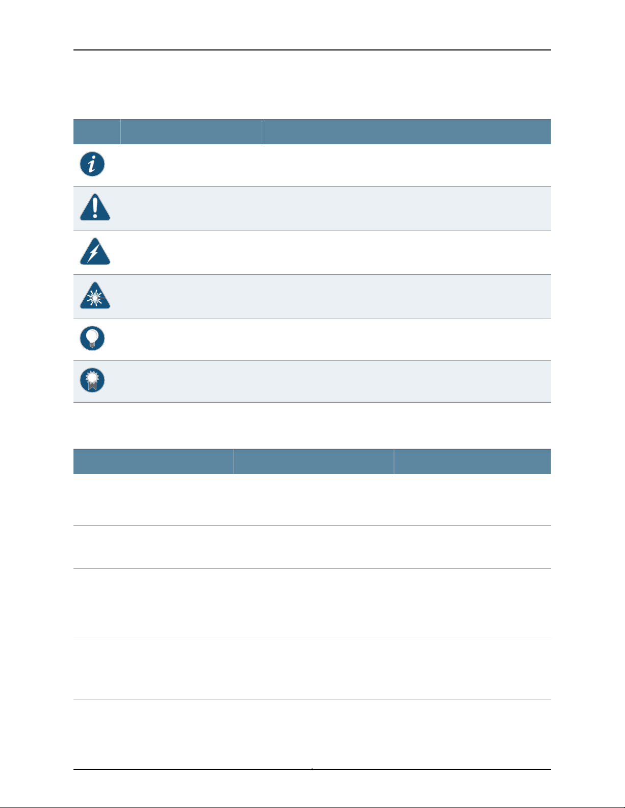
Table 1: Notice Icons
DescriptionMeaningIcon
Indicates important features or instructions.Informational note
Indicates a situation that might result in loss of data or hardware damage.Caution
Alerts you to the risk of personal injury or death.Warning
Alerts you to the risk of personal injury from a laser.Laser warning
Indicates helpful information.Tip
Table 2 on page xvi defines the text and syntax conventions used in this guide.
Table 2: Text and Syntax Conventions
Represents text that you type.Bold text like this
Fixed-width text like this
Italic text like this
Italic text like this
Represents output that appears on the
terminal screen.
•
Introduces or emphasizes important
new terms.
•
Identifies guide names.
•
Identifies RFC and Internet draft titles.
Represents variables (options for which
you substitute a value) in commands or
configuration statements.
Alerts you to a recommended use or implementation.Best practice
ExamplesDescriptionConvention
To enter configuration mode, type the
configure command:
user@host> configure
user@host> show chassis alarms
No alarms currently active
•
A policy term is a named structure
that defines match conditions and
actions.
•
Junos OS CLI User Guide
•
RFC 1997, BGP Communities Attribute
Configure the machine’s domain name:
[edit]
root@# set system domain-name
domain-name
Copyright © 2017, Juniper Networks, Inc.xvi
Page 17

Table 2: Text and Syntax Conventions (continued)
Text like this
Represents names of configuration
statements, commands, files, and
directories;configurationhierarchylevels;
or labels on routing platform
components.
About the Documentation
ExamplesDescriptionConvention
•
To configure a stub area, include the
stub statement at the [edit protocols
ospf area area-id] hierarchy level.
•
The console port is labeled CONSOLE.
stub <default-metric metric>;Encloses optional keywords or variables.< > (angle brackets)
| (pipe symbol)
# (pound sign)
[ ] (square brackets)
Indention and braces ( { } )
; (semicolon)
GUI Conventions
Bold text like this
Indicatesa choice between the mutually
exclusivekeywordsor variables on either
side of the symbol. The set of choices is
often enclosed in parentheses for clarity.
same line as the configurationstatement
to which it applies.
Encloses a variable for which you can
substitute one or more values.
Identifies a level in the configuration
hierarchy.
Identifies a leaf statement at a
configuration hierarchy level.
Representsgraphicaluser interface (GUI)
items you click or select.
broadcast | multicast
(string1 | string2 | string3)
rsvp { # Required for dynamic MPLS onlyIndicates a comment specified on the
community name members [
community-ids ]
[edit]
routing-options {
static {
route default {
nexthop address;
retain;
}
}
}
•
In the Logical Interfaces box, select
All Interfaces.
•
To cancel the configuration, click
Cancel.
> (bold right angle bracket)
Documentation Feedback
We encourage you to provide feedback, comments, and suggestions so that we can
improve the documentation. You can provide feedback by using either of the following
methods:
•
Online feedback rating system—On any page of the Juniper Networks TechLibrary site
at http://www.juniper.net/techpubs/index.html,simply click the stars to ratethe content,
and use the pop-up form to provide us with information about your experience.
Alternately, you can use the online feedback form at
http://www.juniper.net/techpubs/feedback/.
Separates levels in a hierarchy of menu
selections.
In the configuration editor hierarchy,
select Protocols>Ospf.
xviiCopyright © 2017, Juniper Networks, Inc.
Page 18

QFX3600 Device Hardware Documentation
•
E-mail—Sendyourcomments to techpubs-comments@juniper.net.Include the document
or topic name, URL or page number, and software version (if applicable).
Requesting Technical Support
Technical product support is availablethrough the Juniper NetworksTechnical Assistance
Center (JTAC). If you are a customer with an active J-Care or Partner Support Service
support contract, or are covered under warranty, and need post-sales technical support,
you can access our tools and resources online or open a case with JTAC.
•
JTAC policies—For a complete understanding of our JTAC procedures and policies,
review the JTAC User Guide located at
http://www.juniper.net/us/en/local/pdf/resource-guides/7100059-en.pdf.
•
Product warranties—For product warranty information, visit
http://www.juniper.net/support/warranty/.
•
JTAC hours of operation—The JTAC centers have resources available 24 hours a day,
7 days a week, 365 days a year.
Self-Help Online Tools and Resources
For quick and easy problem resolution, Juniper Networks has designed an online
self-service portal called the Customer Support Center (CSC) that provides you with the
following features:
•
Find CSC offerings: http://www.juniper.net/customers/support/
•
Search for known bugs: https://prsearch.juniper.net/
•
Find product documentation: http://www.juniper.net/documentation/
•
Find solutions and answer questions using our Knowledge Base: http://kb.juniper.net/
•
Download the latest versions of software and review release notes:
http://www.juniper.net/customers/csc/software/
•
Search technical bulletins for relevant hardware and software notifications:
http://kb.juniper.net/InfoCenter/
•
Join and participate in the Juniper Networks Community Forum:
http://www.juniper.net/company/communities/
•
Open a case online in the CSC Case Management tool: http://www.juniper.net/cm/
To verify service entitlementby productserial number,use our Serial Number Entitlement
(SNE) Tool: https://entitlementsearch.juniper.net/entitlementsearch/
Opening a Case with JTAC
You can open a case with JTAC on the Web or by telephone.
•
Use the Case Management tool in the CSC at http://www.juniper.net/cm/.
•
Call 1-888-314-JTAC (1-888-314-5822 toll-free in the USA, Canada, and Mexico).
Copyright © 2017, Juniper Networks, Inc.xviii
Page 19

About the Documentation
For international or direct-dial options in countries without toll-free numbers, see
http://www.juniper.net/support/requesting-support.html.
xixCopyright © 2017, Juniper Networks, Inc.
Page 20

QFX3600 Device Hardware Documentation
Copyright © 2017, Juniper Networks, Inc.xx
Page 21

PART 1
Overview
•
System Overview on page 3
•
Chassis Components and Descriptions on page 17
•
Cooling System and Airflow on page 27
•
Power Supplies on page 33
1Copyright © 2017, Juniper Networks, Inc.
Page 22

QFX3600 Device Hardware Documentation
Copyright © 2017, Juniper Networks, Inc.2
Page 23

CHAPTER 1
System Overview
•
QFX3600 Device Overview on page 3
•
Understanding Redundancy of QFX3600 and QFX3600-I Components and
Functionality on page 6
•
Understanding QFX Series Virtual Chassis on page 6
•
Understanding QFX Series Virtual Chassis Components on page 10
QFX3600 Device Overview
The Juniper Networks QFX3600 device is a high-speed, multipurpose switch especially
designed for next-generation data centers. The QFX3600 device can be configured as:
•
A standalone switch
•
A Node device in a QFX3000-M or QFX3000-G QFabric system
•
An Interconnect device in a QFX3000-M QFabric system
•
A member in a QFX Virtual Chassis
•
A leaf node in a QFX5100 Virtual Chassis Fabric (VCF)
Sixteen40-Gbps ports in the device use quad small form-factorpluggable plus (QSFP+)
transceivers. The small form-factor and front facing ports in the switch make it suitable
fordeployment in high-density serverracks and container-baseddata center deployments.
In a QFX3000-G QFabric system, the QFX3600 device can operate as a Node device
through the 40-Gbps uplinks ports to a Juniper Networks QFX3008-I Interconnectdevice.
On a QFX3000-M QFabric device, the QFX3600 can be configured to operate as either
a Node device or as a QFX3600-I Interconnectdevice. When configured as a Node device
in a QFX3000-M QFabric system, , the QFX3600 device can connect to either a
QFX3600-I Interconnect device to a QFX5100-24Q through the 40-Gbps uplink
ports.Together, the QFX3600 Node devices and Interconnect devices form a multistage,
nonblocking switch fabric that provides a high-performance, low-latency, unified
interconnect solution for next-generation data centers.
The QFX3600 Node devices and QFX3008-I or QFX3600-I Interconnect devices are
connected to Juniper Networks QFX3100 Director devices in a control plane and
managementnetwork. The QFX3100 Director device presents the QFabric system devices
3Copyright © 2017, Juniper Networks, Inc.
Page 24

QFX3600 Device Hardware Documentation
as a single network entity, allowing for simplified management of your data center using
the Junos OS command-line interface (CLI).
In a QFX Virtual Chassis, the QFX3600 device can participatewith other QFX3600 devices
or QFX3500 devices in a ring topology with up to 10 members.
In a QFX5100 Virtual Chassis Fabric, the QFX3600 device can participate as a leafdevice.
Up to a total of 32 devices can participate in the Virtual Chassis Fabric.
•
Software on page 4
•
Hardware on page 4
Software
QFX Series devices use the Junos operating system (OS), which provides Layer 2 and
Layer 3 switching, routing, and security services. Junos OS is installed on the QFX3600
device’s 8-gigabyte (GB) internal flash drive. The same Junos OS code base that runs
on QFX Series devices also runs on all Juniper Networks EX Series, J Series, M Series, MX
Series, and T Series devices.
Hardware
For more information about which features are supported on QFX Series devices, see
Feature Explorer.
When the QFX3600 device is operating as a standalone switch, you manage the switch
using the Junos OS command-line interface (CLI), accessible through the console and
out-of-band management ports on the device.
When a QFX Series device operates as part of a QFabric system, all the devices in the
data center fabric are managed through the Administrator software installed on the
QFX3100 Director devices. Each device in a QFabric system is interconnected in a single
control plane and management network, using the redundant management ports on
each device.
The compact QFX3600 chassis is 1 rack unit (1 U) in size and designed to fit in
industry-standard 19-inch rack-mount enclosures, as well as high-density server racks
and container-based data center deployments. See Figure 1 on page 5 and
Figure 2 on page 5 and “Chassis Physical Specifications for QFX3600 and QFX3600-I
Devices” on page 17.
Copyright © 2017, Juniper Networks, Inc.4
Page 25
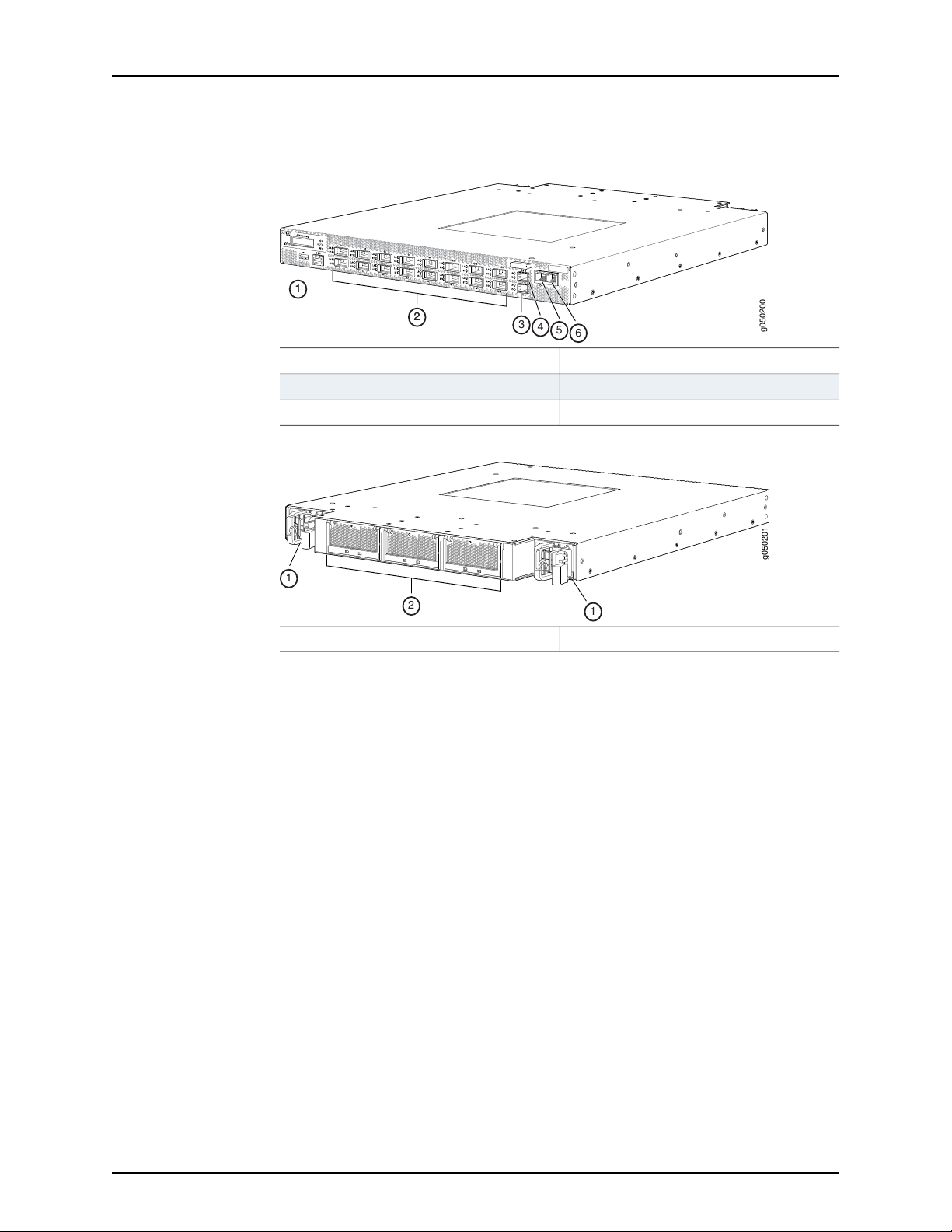
Figure 1: QFX3600 Chassis Front
g050200
3
4
5
6
2
1
2
1
g050201
AC
!
DC
1
1
2
Chapter 1: System Overview
LCD panel
QSFP+ ports
4—1—
C0S 1-Gbps SFP management port
5—2—
C0 1000BASE-T RJ-45 management port
6—3—
C1 1000BASE-T RJ-45 management portC1S 1-Gbps SFP management port
Figure 2: QFX3600 Chassis Rear
2—1— Fan traysPower supplies
The front panel of the QFX3600 chassis has an LCD panel that displays the device
hostname and the number of active alarms. It also has sixteen 40-Gbps ports labeled
Q0 through Q15 thatsupport quad small form-factorpluggableplus (QSFP+) transceivers.
See “Front Panel of a QFX3600 Device” on page 19.
If you are using the QFX3600 device as a Node device in a QFabric system, by default,
four ports (labeled Q0 through C3) are configured for uplink connections between your
QFX3600 Node device and your Interconnect device, and twelve ports (labeled Q4
through Q15) support 48 10-Gigabit Ethernet or 12 40-Gigabit Ethernet interfaces for
connectionsto either endpoint systems(such as servers and storagedevices)or external
networks.Optionally,you can choose to configure the first eight ports (labeled Q0 through
Q7) for uplink connections between your QFX3600 Node device and your Interconnect
device and ports Q2 through Q15 for 10-Gigabit Ethernet or 40-Gigabit Ethernet
connections to either endpoint systems or external networks. See Configuring the Port
Type on QFX3600 Node Devices and “Determining Interface Support for the QFX3600
Device” on page 55.
If you are using the QFX3600 device as a standalone switch, by default, all 16 QSFP+
ports (Q0 through Q15) are configured as 40-Gigabit Ethernet (xle) ports. Optionally,
you can choose to configure each port to operate as 10-Gigabit Ethernet (xe) ports. Port
00 is unique because the number of ports you can specify as 10-Gigabit Ethernet varies
by Junos OS release. In some Junos OS releases, port 00 has a reserved port and in other
5Copyright © 2017, Juniper Networks, Inc.
Page 26
QFX3600 Device Hardware Documentation
releases, the port is available. See the topics on channelizing interfaces or configuring
the port type for your specific software release.
The rear panel of the QFX3600 chassis has two redundant power supplies and three
redundant fan trays that are field-replaceable and hot-swappable. See “Rear Panel of
QFX3600 and QFX3600-I Devices” on page 21.
Related
Documentation
Field-Replaceable Units for QFX3600 and QFX3600-I Devices on page 18•
• Site Preparation Checklist for a QFX3600 or QFX3600-I Device on page 43
• Installing and Removing QFX3600 or QFX3600-I Device Hardware Components on
page 117
Understanding Redundancy of QFX3600 and QFX3600-I Components and Functionality
The following hardware components provide redundancy on QFX3600 and QFX3600-I
devices:
•
Power supplies—QFX3600 and QFX3600-I devices have two power supplies. Each
power supply provides power to all components in the device. The two power supplies
provide full power redundancy to the device. If one power supply fails or is removed,
the second power supply balances the electrical load without interruption.
To provide power redundancy to the system both power supplies must be installed.
Connect power source feed A to one power supply and power source feed B to the
second power supply.
CAUTION: Do not connect feed A and feed B to the same power supply
input terminal.
•
Cooling system—QFX3600and QFX3600-I devices havethree fan trays.If a fan module
on a fan tray fails and is unable to keep the QFX3600 device within the desired
temperature thresholds, chassis alarms occur and the device may shut down.
Related
Documentation
AC Power Supply for a QFX3500, QFX3600, or QFX3600-I Device on page 33•
• DC Power Supply for a QFX3500, QFX3600, or QFX3600-I Device on page 35
• Cooling System and Airflow for QFX3600 and QFX3600-I Devices on page 27
Understanding QFX Series Virtual Chassis
This topic discusses QFX Series Virtual Chassis. A QFX Series Virtual Chassis is a supported
combination of interconnected QFX3500, QFX3600, QFX5100, QFX5110, and EX4300
switches operating as one logical device and managed as a single chassis. Switches in
a Virtual Chassis are called members of the Virtual Chassis.
Copyright © 2017, Juniper Networks, Inc.6
Page 27

This topic does not discuss Virtual Chassis Fabric (VCF). For informationon understanding
VCF, see Virtual Chassis Fabric Overview.
This topic includes:
•
QFX Virtual Chassis Overview on page 7
•
QFX5110 Switches in a Virtual Chassis on page 8
•
QFX5100 Switches in a Virtual Chassis on page 8
•
QFX3500 and QFX3600 Switches in a Virtual Chassis on page 9
•
EX4300 Switches in a QFX Series Virtual Chassis on page 9
QFX Virtual Chassis Overview
A QFX Series Virtual Chassis is a flexible, scaling switch solution for supported
combinationsof QFX3500, QFX3600,QFX5100,and QFX5110 switches. EX4300 switches
can also be included in some configurations of a QFX Series Virtual Chassis..
In a QFX Series Virtual Chassis, you can interconnect up to ten standalone switches in
the following combinations into one logical device, and manage the logical device as a
single chassis:
Chapter 1: System Overview
•
QFX5110 switches or a combination of QFX5110 and QFX5100 switches (a non-mixed
Virtual Chassis)
•
QFX5100 switches (a non-mixed Virtual Chassis)
•
QFX5100 switches with any combinationof QFX3500, QFX3600,or EX4300 switches
(a mixed mode Virtual Chassis)
•
QFX3500switches or QFX3600 switches, or a combination of QFX3500 and QFX3600
switches (a non-mixed Virtual Chassis)
•
QFX3500 or QFX3600 switches with EX4300 switches, or a combination of all three
types of switches (a mixed mode Virtual Chassis)
The advantages of connecting multiple switches into a Virtual Chassis include
better-managed bandwidth at a networklayer, simplified configurationand maintenance
because multiple devices can be managed as a single device, increased fault tolerance
and high availability(HA) because a Virtual Chassis can remain active and network traffic
can be redirected to other member switches when a single member switch fails, and a
flatter, simplified Layer 2 network topology that minimizes or eliminates the need for
loop prevention protocols such as Spanning Tree Protocol (STP).
You set up a Virtual Chassis by configuring Virtual Chassis ports (VCPs) on the member
switches, and interconnecting the switches using the VCPs . VCPs are responsible for
passing all data and control traffic between member switches in theVirtual Chassis. The
following ports on QFX Series switches that support Virtual Chassis can be configured
into VCPs to form a QFX Series Virtual Chassis:
•
Any 100-Gbps or 40-Gbps QSFP28 ports on QFX5110 switches
•
Any non-channelized 40-Gbps QSFP+ ports on QFX3500, QFX3600, QFX5100, or
QFX5110 switches
7Copyright © 2017, Juniper Networks, Inc.
Page 28

QFX3600 Device Hardware Documentation
•
Any fixed 10-Gbps SFP+ ports on QFX Series switches with these ports
See EX4300 Switches Hardware Overview for details on the ports on an EX4300 switch
that can be configured into VCPs in a QFX Series Virtual Chassis.
You can increase VCP bandwidth between member switches by configuring multiple
interfaces between the same two switches into VCPs. When multiple VCPs interconnect
the same two member switches, a Link Aggregation Group (LAG) or bundle is
automatically formed when the VCPs are on interfaces supporting identical speeds. For
example, if you have two 40-Gbps QSFP+ interfaces configured as VCPs between
member switches, a LAG with two member links with 80Gbps of total bandwidth is
formed. However, 10-Gbps SFP+ and 40-Gbps QSFP+ interfaces configured as VCPs
will not become members of the same VCP LAG.
QFX5110 Switches in a Virtual Chassis
Starting in Junos OS Release 17.3R1, Virtual Chassis is supported on QFX5110 switches.
You can interconnect up to ten QFX5110 switches or a combination of QFX5110 and
QFX5100 switches intoa QFX5110 Virtual Chassis. All switches can run the same software
image, and you do not need to configure mixed mode.
The following QFX5110 and QFX5100 switches are supported in a QFX5110 Virtual Chassis:
•
QFX5110-32Q
•
QFX5110-48S
•
QFX5100-24Q
•
QFX5100-48S
•
QFX5100-96S
QFX5100 Switches in a Virtual Chassis
Starting in Junos OS Release 13.2X51-D20, Virtual Chassis is supported on QFX5100
switches.You can interconnect up to ten switches into a QFX5100 Virtual Chassis that
can include any combination of QFX5100, QFX3500, QFX3600, and EX4300 switches.
NOTE: In Junos OS release13.2X51-D20, you can interconnect only up to four
QFX5100-96S switches in a non-mixed QFX5100 Virtual Chassis. Starting
in Junos OS release 13.2X51-D25, you can configure up to ten QFX5100-96S
switches into a mixed or non-mixed QFX Series Virtual Chassis.
The following QFX5100 switches are supported in a non-mixed QFX5100 Virtual Chassis
or a mixed QFX5100 Virtual Chassis (QFX5100 switches with QFX3500, QFX3600, or
EX4300 switches):
•
QFX5100-24Q
•
QFX5100-48S
Copyright © 2017, Juniper Networks, Inc.8
Page 29
Chapter 1: System Overview
•
QFX5100-48T
•
QFX5100-96S
NOTE: QFX5100-24Q switches should be configured as the Routing Engine
role members in a mixed QFX5100 Virtual Chassis.
QFX5100 switches can also be part of a QFX5110 Virtual Chassis, which can include a
combination of up to ten QFX5110 and QFX5100 switches. For a QFX5100 switch to
participatein a QFX5110 Virtual Chassis, the switchmust have the same software version
and image installed as the software running on the QFX5110 switches in the Virtual
Chassis. You do not need to configure mixed mode. In a QFX5110 Virtual Chassis, we
recommend to use QFX5110 switches in the master and backup Routing Engine roles,
and QFX5100 switches only in the linecard role.
The following QFX5100 switches are supported in a QFX5110 Virtual Chassis:
•
QFX5100-24Q
•
QFX5100-48S
•
QFX5100-96S
CAUTION: A QFX5100 switch running a Junos OS software image with
“-qfx-5-” in the package filename must first be upgraded to a Junos OS
software image with “-qfx-5e-” in the package filename before it can be
added to a QFX5110 Virtual Chassis or VCF. See Upgrading a QFX5100 Switch
with a USB Device to Join a QFX5110 Virtual Chassis or Virtual Chassis Fabric.
QFX3500 and QFX3600 Switches in a Virtual Chassis
Virtual Chassis is supported on QFX3500 and QFX3600 series switches. To be included
in a Virtual Chassis, QFX3500 and QFX3600 series switches must be configured as
standalone switches and not as QFX node devices in a QFabric system.
QFX3500 and QFX3600 devices must be running a version of Junos OS for QFX devices
that supports Virtual Chassis,and can be in a Virtual Chassiswith up to ten total members
including QFX3500 or QFX3600 switches only, or any combination of QFX3500,
QFX3600, QFX5100, and EX4300 switches.
EX4300 Switches in a QFX Series Virtual Chassis
Virtual Chassis is supported on EX4300 switches. Starting in Junos OS Release
13.2X51-D20, EX4300 switches can be interconnected into a QFX Series Virtual Chassis
with QFX3500 switches, QFX3600 switches, and QFX5100 switches.
A mixed or non-mixed QFX Series Virtual Chassis that includes EX4300 switches can
contain up to ten total member switches including any combination of QFX3500,
QFX3600, and QFX5100 switches with EX4300 switches.
9Copyright © 2017, Juniper Networks, Inc.
Page 30

QFX3600 Device Hardware Documentation
Release History Table DescriptionRelease
Starting in Junos OS Release 17.3R1, Virtual Chassis is supported on
QFX5110 switches.
Starting in Junos OS release 13.2X51-D25, you can configure up to ten
QFX5100-96S switches into a mixed or non-mixed QFX Series Virtual
Chassis.
Starting in Junos OS Release 13.2X51-D20, Virtual Chassis is supported on
QFX5100 switches.
In Junos OS release 13.2X51-D20, you can interconnect only up to four
QFX5100-96S switches in a non-mixed QFX5100 Virtual Chassis.
Starting in Junos OS Release 13.2X51-D20, EX4300 switches can be
interconnected into a QFX Series Virtual Chassis with QFX3500 switches,
QFX3600 switches, and QFX5100 switches.
Related
Documentation
17.3R1
13.2X53-D25
13.2X51-D20
13.2X51-D20
13.2X51-D20
Understanding QFX Series Virtual Chassis Components on page 10•
• Configuring a QFX Series Virtual Chassis (CLI Procedure) on page 107
Understanding QFX Series Virtual Chassis Components
This topic describes the components of a QFX Series Virtual Chassis. A QFX Series Virtual
Chassis is a supported combination of up to ten standalone QFX3500, QFX3600,
QFX5100,or QFX5110switches interconnectedand managedas a single chassis.(EX4300
switches can also be interconnected into a mixed Virtual Chassis with QFX3500,
QFX3600, and QFX5100 switches.)
This topic does not discuss Virtual Chassis Fabric components. For informationon Virtual
Chassis Fabric components, see Understanding Virtual Chassis Fabric Components.
This topic covers:
•
Virtual Chassis Ports (VCPs) on page 11
•
Maximum Switch Support on page 11
•
Master Routing Engine Role on page 12
•
Backup Routing Engine Role on page 12
•
Linecard Role on page 13
•
Member Switch and Member ID on page 14
•
Mastership Priority on page 14
Copyright © 2017, Juniper Networks, Inc.10
Page 31

Virtual Chassis Ports (VCPs)
You set up a Virtual Chassis by configuring Virtual Chassis ports (VCPs) on the member
switches, and interconnecting the switches using the VCPs. VCPs are responsible for
passing all data and control traffic between member switches in the Virtual Chassis.
The following options are available for configuring VCPs on the switches in a QFX Series
Virtual Chassis:
•
Any 100-Gbps or 40-Gbps QSFP28 ports on QFX5110 switches can be configured into
VCPs.
•
Any non-channelized 40-Gbps QSFP+ interfaces on QFX3500, QFX3600, QFX5100,
and QFX5110 switches can be configured into VCPs.
•
40-Gbps QSFP+ interfaces that have been channelized into SFP+ interfaces using a
breakout cable cannot be configured into VCPs, but all other non-channelized SFP+
interfaces on QFX series switches can be configured into VCPs, and can also be used
to interconnect EX4300 switches into a mixed QFX and EX Series Virtual Chassis.
Chapter 1: System Overview
You can increase VCP bandwidth between member switches by configuring multiple
interfaces between the same two switches into VCPs. When multiple VCPs interconnect
the same two member switches, a Link Aggregation Group (LAG) or bundle is
automatically formed when the VCPs are on interfaces supporting identical speeds. For
example, if you have two 40-Gbps QSFP+ interfaces configured as VCPs between
member switches, a LAG with two member links with 80-Gbps of total bandwidth is
formed. However, 10-Gigabit SFP+ and 40-Gbps QSFP+ interfaces configured as VCPs
will not become members of the same LAG. See Understanding Virtual Chassis Port Link
Aggregation.
Maximum Switch Support
In a QFX Series Virtual Chassis, you can interconnect up to 10 standalone switches in the
following supported combinations:
•
QFX5110 switches or a combination of QFX5110 switches and QFX5100 switches (a
non-mixed Virtual Chassis)
•
QFX5100 switches (a non-mixed Virtual Chassis)
•
QFX5100 switches with any combinationof QFX3500, QFX3600,or EX4300 switches
(a mixed mode Virtual Chassis)
•
QFX3500 switches, or QFX3600 swtiches, or any combination of QFX3500 switches
and QFX3600 switches (a non-mixed Virtual Chassis)
•
Any combination of QFX3500 and QFX3600 switcheswith EX4300 switches (a mixed
mode Virtual Chassis)
11Copyright © 2017, Juniper Networks, Inc.
Page 32

QFX3600 Device Hardware Documentation
Master Routing Engine Role
In a Virtual Chassis, each member switch is assigned one of two roles: Routing Engine or
linecard, and for Routing Engine role, receives a further designation as the master or
backup Routing Engine.
Themember that functions as the masterin the Routing Engine role in the Virtual Chassis:
•
Manages the member switches.
•
Runs Junos OS for the switches as a master Routing Engine.
•
Runs the chassis management processes and control protocols.
NOTE: In Junos OS release13.2X51-D20, you can interconnect only up to four
QFX5100-96S switches in a non-mixed QFX5100 Virtual Chassis. Starting
in Junos OS release 13.2X51-D25, you can configure up to ten QFX5100-96S
switches into a mixed or non-mixed QFX5100 Virtual Chassis.
•
Represents all the member switches interconnected within the Virtual Chassis
configuration.(The hostname and other properties that you assign to this switch during
setup apply to all members of the Virtual Chassis configuration.)
In a preprovisioned configuration, one of the two members assigned as routing-engine
functions as the master member. The selection of which member assigned as
routing-engine functions as master and which as backup is determined by the software
based on the master election algorithm. See Understanding How the Master in a Virtual
Chassis Is Elected.
In a configuration that is not preprovisioned, the selection of the master and backup is
determined by the mastership priority value and secondary factorsin the master election
algorithm.
All switches that are not assigned the master or backup Routing Engine role function in
the linecard role.
In a QFX5110 Virtual Chassis with QFX5110 and QFX5100 switches, we recommend
configuring only QFX5110 switches into the Routing Engine role.
In a mixed QFX Series Virtual Chassis made up of QFX5100 switches with QFX3500,
QFX3600, or EX4300 switches, we recommend configuring QFX5100 switches into the
Routing Engine role. If the mixed Virtual Chassis does not contain QFX5100 switches, we
recommend configuring QFX3500 or QFX3600 switches into the Routing Engine role.
Backup Routing Engine Role
The member that functions in the backup Routing Engine role in a Virtual Chassis:
•
Maintains a stateof readiness to take over the master Routing Engine role if the master
fails.
•
Runs Junos OS for the switches as a backup Routing Engine.
Copyright © 2017, Juniper Networks, Inc.12
Page 33

Chapter 1: System Overview
•
Synchronizeswith the master in terms of protocol states, forwarding tables, and other
information,so that it is prepared to preserve routing information and maintain network
connectivity without disruption in case the master is unavailable.
You must have at least two member switches in the Virtual Chassis configuration in order
to have a backup Routing Engine member.
In a preprovisioned configuration, one of the two members assigned as routing-engine
functions in the backup role. The selection of which member assigned as routing-engine
functions as master and which as backup is determined by the software based on the
master election algorithm. See Understanding How the Master in a Virtual Chassis Is
Elected.
In a configuration that is not preprovisioned, the selection of the master and backup is
determined by the mastership priority value and secondary factorsin the master election
algorithm.
In a QFX5110 Virtual Chassis with QFX5110 and QFX5100 switches, we recommend
configuring only QFX5110 switches into the Routing Engine role.
Linecard Role
In a mixed QFX Series Virtual Chassis made up of QFX5100 switches with QFX3500,
QFX3600, or EX4300 switches, we recommend configuring the QFX5100 switches into
the Routing Engine role. If the mixed Virtual Chassis does not contain QFX5100 switches,
we recommend configuringQFX3500 or QFX3600 switches into the Routing Engine role.
A member that functions in the linecard role in a Virtual Chassis:
•
Runs only a subset of Junos OS.
•
Does not run the chassis control protocols.
•
Can detect certain error conditions (such as an unplugged cable) on any interfaces
that have been configured on it through the master.
The Virtual Chassis configuration must have at least three members in order to include
a linecard member.
In a preprovisioned configuration, you can explicitly configure a member with the linecard
role, which makes it ineligible for functioning as a master or backup Routing Engine.
In a configurationthat is not preprovisioned,the members that are not selectedas master
or backup function as linecard members of the Virtual Chassis configuration.The selection
of the master and backup is determined by the mastership priority value and secondary
factors in the masterelection algorithm. A switch with a mastership priority of 0 is always
in the linecard role.
Any switch can function in the linecard role in a mixed or non-mixed Virtual Chassis.
In a QFX5110 Virtual Chassis made up of QFX5110 and QFX5100 switches,we recommend
configuring only QFX5110 switches into the Routing Engine role.
13Copyright © 2017, Juniper Networks, Inc.
Page 34

QFX3600 Device Hardware Documentation
In a mixed QFX Series Virtual Chassis made up of QFX5100 switches with QFX3500,
QFX3600, or EX4300 switches, we recommend configuring the QFX5100 switches into
the Routing Engine role. If the mixed Virtual Chassis does not contain QFX5100 switches,
we recommend configuringQFX3500 or QFX3600 switches into the Routing Engine role.
Member Switch and Member ID
Each standalone switch that supports Virtual Chassis is a potential member of a Virtual
Chassis configuration. When one of those switches is powered on, it receives a member
ID that can be seen by viewing the front-panel LCD or by entering the show virtual-chassis
command. If the switch is powered on as a standalone switch, that member’s member
ID is always0. When the switch is interconnectedwith other switches in a Virtual Chassis
configuration, its member ID is assigned by the master based on various factors, such as
the order in which the switch was added to the Virtual Chassis configuration or the
member ID assigned by a preprovisionedconfiguration.See Understanding How the Master
in a Virtual Chassis Is Elected.
If the Virtual Chassis configuration previously included a member switch and that member
was physically disconnected or removed from the Virtual Chassis configuration, its
member ID is not availablefor assignment as part of the standard sequential assignment
by the master. For example, you might have a Virtual Chassis configuration composed
of member 0, member 2, and member 3, because member 1 was removed. When you
add another member switch and power it on, the master assigns it as member 4.
Mastership Priority
Themember ID distinguishes the member switches fromone another.You use the member
ID:
•
To assign a mastership priority value to a member switch
•
To configure interfaces for a member switch (The function is similar to that of a slot
number on Juniper Networks routers.)
•
To apply some operational commands to a member switch
•
To display status or characteristics of a member switch
In a configurationthat is not preprovisioned,youcan designate the role (master or backup
RoutingEngine, or linecard) that a member switch assumes by configuring its mastership
priority (from 0 through 255). The mastership priority value is the factor in the master
election algorithm with the highest precedence for selecting the master of the Virtual
Chassis configuration. A switch with a mastership priority of 0 never assumes the backup
or master Routing Engine role.
The default value for mastership priority is 128. When a standalone switch is powered
on, it receives the default mastership priority value. Because it is the only member of the
Virtual Chassis configuration, it is also the master. When you interconnect a standalone
switch to an existing Virtual Chassis configuration (which implicitly includes its own
master), we recommend that you explicitly configure the mastership priority of the
members that you want to function as the master and backup.
Copyright © 2017, Juniper Networks, Inc.14
Page 35

In a preprovisioned configuration, you assign the role of each member switch.
Release History Table DescriptionRelease
Chapter 1: System Overview
Related
Documentation
13.2X53-D25
13.2X51-D20
• Understanding QFX Series Virtual Chassis on page 6
• Configuring a QFX Series Virtual Chassis (CLI Procedure) on page 107
Starting in Junos OS release 13.2X51-D25, you can configure up to ten
QFX5100-96S switches into a mixed or non-mixed QFX5100 Virtual
Chassis.
In Junos OS release 13.2X51-D20, you can interconnect only up to four
QFX5100-96S switches in a non-mixed QFX5100 Virtual Chassis.
15Copyright © 2017, Juniper Networks, Inc.
Page 36

QFX3600 Device Hardware Documentation
Copyright © 2017, Juniper Networks, Inc.16
Page 37

CHAPTER 2
Chassis Components and Descriptions
•
Chassis Physical Specifications for QFX3600 and QFX3600-I Devices on page 17
•
Field-Replaceable Units for QFX3600 and QFX3600-I Devices on page 18
•
Front Panel of a QFX3600 Device on page 19
•
Rear Panel of QFX3600 and QFX3600-I Devices on page 21
•
Access Port and Uplink Port LEDs on a QFX3600 or QFX3600-I Device on page 21
•
Chassis Status LEDs in the QFX3600 and QFX3600-I Device on page 23
•
Management Port LEDs in the QFX3600 and QFX3600-I Device on page 24
Chassis Physical Specifications for QFX3600 and QFX3600-I Devices
The QFX3600 and QFX3600-I chassis is a rigid sheet-metal structure that houses the
hardware components. Table 3 on page 17 summarizes the physical specifications of
the QFX3600 and QFX3600-I chassis.
Table 3: Chassis Physical Specifications for QFX3600 and QFX3600-I Devices
Chassis width
Chassis depth
Weight
Documentation
Related
ValueDescription
1.74 in. (4.4 cm)Chassis height
•
Including mounting brackets: 19.2 in. (48.8 cm)
•
Excluding mounting brackets: 16.9 in. (42.9 cm)
•
Including FRU handles and locking levers: 19.4 in. (49.3 cm)
•
Excluding FRU handles and locking levers: 19.3 in. (49 cm)
•
With FRUs installed: 20.5 lb (9.3 kg)
•
Without FRUs installed: 14.6 lb (6.6 kg)
•
AC power supply: 2.2 lb (1 kg)
•
DC power supply: 2.2 lb (1 kg)
•
Fan tray: 0.9 lb (0.4 kg)
Rack Requirements for a QFX3600 or QFX3600-I Device on page 46•
• Cabinet Requirements for a QFX3600 or QFX3600-I Device on page 48
17Copyright © 2017, Juniper Networks, Inc.
Page 38

QFX3600 Device Hardware Documentation
• Installing and Connecting a QFX3600 or QFX3600-I Device on page 71
• Installing and Removing QFX3600 or QFX3600-I Device Hardware Components on
page 117
Field-Replaceable Units for QFX3600 and QFX3600-I Devices
Field-replaceable units (FRUs) are components that you can replace at your site.
QFX3600 and QFX3600-I device FRUs are hot-insertable and hot-removable: you can
remove and replace them without powering off the device or disrupting the switching
function.
CAUTION: Replace a failed power supply with a blank panel or new power
supply within 1 minute of removal to prevent chassis overheating. Replace a
failed fan tray with a new fan tray within 1 minute of removal to prevent
chassis overheating.
Table 4 on page 18 lists the FRUs for QFX3600 and QFX3600-I devices and actions to
take before removing them.
Table 4: Field-Replaceable Units for QFX3600 and QFX3600-I Devices
Required ActionFRU
None.Power supplies
None.Fan trays
Optical transceivers
None. We recommend that you disable the interface using the set interfaces
interface-namedisablecommand before you remove the transceiver. See Disconnecting
a Fiber-Optic Cable from a QFX Series Device.
NOTE: If you have a Juniper J-Care service contract, register any addition,
change, or upgrade of hardware components at
https://www.juniper.net/customers/csc/management/updateinstallbase.jsp .
Failureto do so can resultin significant delays if you need replacement parts.
This note does not apply if you replace existing components with the same
type of component.
Related
Documentation
Installing and Removing QFX3600 or QFX3600-I Device Hardware Components on
•
page 117
Copyright © 2017, Juniper Networks, Inc.18
Page 39

Front Panel of a QFX3600 Device
The front panel of the QFX3600 device consists of the following components:
•
LCD panel—The LCD panel displays the device hostname and the number of active
alarms.
TIP: Alternatively, you can use the show chassis lcd CLI command to view
what is currently displayed on the LCD panel.
•
Chassis status LEDs
•
USB port
•
Console (CON) port
•
Management ports—The QFX3600 device has four management ports. The ports
labeled C0 and C1 are 1000BASE-T RJ-45 ports, and the ports labeled C0S and C1S
are 1-Gbps SFP ports.
Chapter 2: Chassis Components and Descriptions
•
If you are using the QFX3600 device as a Node device in a QFabric system, these
ports are used to connect the QFX3600 device to the QFabric system control plane
and management network. See Determining Transceiver Support for QFabric Systems
for information about the supported transceivers and required cables.
•
If you are using the QFX3600 device as a standalone switch, these ports are used
to connect the QFX3600 deviceto a management network.See “Cable Specifications
for Console and Management Connections for the QFX Series” on page 58 for
information about the required cables.
NOTE: When an SFP transceiver is inserted into a management port, the
correspondingRJ-45 management port (C0 or C1) is disabled. Either RJ-45
or SFP management ports can be used, but not both.
•
Chassis serial number label and ESD point
NOTE: The chassis serial number ID label is located on a sliding panel on
the top right of the front panel on a QFX3600 device (see
Figure 3 on page 20). To use the sliding panel as an ESD point, pull the
sliding panel partway out of the chassis, and connect a tape-style ESD
grounding strap to the panel.
•
Access and uplink ports—The QFX3600 device has sixteen 40-Gbps ports labeled Q0
through Q15 that support quad small form-factor pluggable plus (QSFP+) transceivers.
•
If you are using the QFX3600 device asa Node device in a QFabric system, bydefault,
four ports (labeled Q0 through Q3) are configured for uplink connections between
your QFX3600 Node device and your Interconnect device, and twelve ports (labeled
19Copyright © 2017, Juniper Networks, Inc.
Page 40

OK /!
QFX3600-16Q
CON
LA
ST
LA
ST
Q0
Q1
LA
ST
LA
ST
Q2
Q3
LA
ST
LA
ST
Q4
Q5
LA
ST
LA
ST
Q6
Q7
LA
ST
LA
ST
Q8
Q9
LA
ST
LA
ST
Q10
Q11
LA
ST
LA
ST
Q12
Q13
LA
ST
LA
ST
Q14
Q15
LA
ST
LA
ST
C1S
C0
C1
C0S
g050202
8
7
6
5
10
2
4
9
1
3
QFX3600 Device Hardware Documentation
Q4 through Q15) use QSFP+ direct-attach copper (DAC) breakout cables or QSFP+
transceivers with fiber breakout cables to support 48 10-Gigabit Ethernet interfaces
for connections to either endpoint systems (such as servers and storage devices)
or external networks. Optionally, you can choose to configure the first eight ports
(labeledQ0 through Q7) for uplinkconnections between your QFX3600 Node device
and your Interconnect device and ports Q2 through Q15 for 10-Gigabit Ethernet
connections to either endpoint systems or external networks. See Determining
Transceiver Support for QFabric Systems.
•
If you are using the QFX3600 device as a standalone switch, by default, all 16 QSFP+
ports (Q0 through Q15) are configuredas 40-Gigabit Ethernet (xle)ports. Optionally,
you can choose to configure each port to operate as 10-Gigabit Ethernet (xe) ports.
The number of ports supported is release dependent. See “Configuring the Port Type
on QFX3600 StandaloneSwitches” on page 133 for your releasefor moreinformation
about configuring the port type. You can use QSFP+ direct-attach copper (DAC)
cables, QSFP+ DAC breakout cables, or QSFP+ transceivers. You can use QSFP+
transceivers to create four 10-Gigabit Ethernet ports by using a fiber breakout cable
to distribute the interfaces to four 10GBASE-SR SFP+ transceivers. (Juniper Networks
does not sell fiber breakout cables, they must be purchased separately.) See
“Determining Interface Support for the QFX3600 Device” on page 55.
Related
Documentation
•
Access port and uplink port LEDs
Figure 3 on page 20 shows the front of a QFX3600 device.
Figure 3: QFX3600 Device Front Panel
LCD panel
Chassis status LEDs
Access and uplink ports
Chassis serial number label and ESD point
C1 management port
Field-Replaceable Units for QFX3600 and QFX3600-I Devices on page 18•
• Rear Panel of QFX3600 and QFX3600-I Devices on page 21
• USB Port Specifications for the QFX Series on page 65
6—1—
C0 management port
7—2—
C0S management port
8—3—
C1S management port
9—4—
Console (CON) port
10—5— USB port
• Chassis Status LEDs in the QFX3600 and QFX3600-I Device on page 23
• Access Port and Uplink Port LEDs on a QFX3600 or QFX3600-I Device on page 21
• Prevention of Electrostatic Discharge Damage on page 200
Copyright © 2017, Juniper Networks, Inc.20
Page 41

• Installing and Removing QFX3600 or QFX3600-I Device Hardware Components on
g050203
2
4
1
3
page 117
Rear Panel of QFX3600 and QFX3600-I Devices
The rear panel of QFX3600 and QFX3600-I devices consists of the followingcomponents:
•
Fan trays
•
Grounding point
•
Power supplies
Figure 4 on page 21 shows the rear panel of a QFX3600 device.
Figure 4: QFX3600 and QFX3600-I Device Rear Panel
Chapter 2: Chassis Components and Descriptions
3—1—
Fan trays 0-2Power supply 0
4—2—
Power supply 1
Related
Documentation
Grounding point
Field-Replaceable Units for QFX3600 and QFX3600-I Devices on page 18•
• Front Panel of a QFX3600 Device on page 19
• Cooling System and Airflow for QFX3600 and QFX3600-I Devices on page 27
• Grounding Cable and Lug Specifications for QFX3600 and QFX3600-I Devices on
page 53
• AC Power Supply for a QFX3500, QFX3600, or QFX3600-I Device on page 33
• DC Power Supply for a QFX3500, QFX3600, or QFX3600-I Device on page 35
• Prevention of Electrostatic Discharge Damage on page 200
• Installing and Removing QFX3600 or QFX3600-I Device Hardware Components on
page 117
Access Port and Uplink Port LEDs on a QFX3600 or QFX3600-I Device
Each access port and uplink port in a QFX3600 device has two LEDs (see
Figure 5 on page 22).
21Copyright © 2017, Juniper Networks, Inc.
Page 42

g050209
Link /Activity
LED
Status
LED
QFX3600 Device Hardware Documentation
Figure 5: LEDs on the QSFP+ Access and Uplink Ports
The LEDs labeled Link/Activity LED in Figure 5 on page 22 indicate link activity or faults.
The LEDs labeled Status LED in Figure 5 on page 22 indicate link status.
Table 5 on page 22 describes the QSFP+ access port LEDs.
Table 5: Access Port LEDs on QSFP+ Ports on a QFX3600 Device
DescriptionStateColorLED
OffUnlitLink/Activity
On steadilyGreen
Blinking
No link is established, there is a fault, or the link is down.
NOTE: The LED remains unlit only if all four of the 10-Gigabit Ethernet
SFP+ breakout links are down.
A link is established, but there is no link activity.
NOTE: The LED is lit green when at least one of the four 10-Gigabit Ethernet
SFP+ breakout links is established.
A link is established, and there is link activity.
NOTE: The LED is lit green when at least one of the four 10-Gigabit Ethernet
SFP+ breakout links is established.
No transceiver is installed in the port, or the transceiver is not supported.OffUnlitStatus
A transceiver is installed in the port.On steadilyGreen
Table 6 on page 22 describes the QSFP+ uplink port LEDs.
Table 6: Uplink Port LEDs on a QFX3600 or QFX3600-I Device
DescriptionStateColorLED
No link is established, there is a fault, or the link is down.OffUnlitLink/Activity
A link is established, but there is no link activity.On steadilyGreen
A link is established, and there is link activity.Blinking
OffUnlitStatus
No transceiver is installed in the port, or the transceiver is not
supported.
A transceiver is installed in the port.On steadilyGreen
Copyright © 2017, Juniper Networks, Inc.22
Page 43

g050204
Status
Fan
Power
Chapter 2: Chassis Components and Descriptions
Related
Documentation
Front Panel of a QFX3600 Device on page 19•
• Front Panel of a QFX3600-I Interconnect Device
• Installing a Transceiver in a QFX Series Device
• Connecting a Fiber-Optic Cable to a QFX Series Device
Chassis Status LEDs in the QFX3600 and QFX3600-I Device
The front panel of the QFX3600 and QFX3600-I device has three LEDs on the right side
of the management board, next to the LCD panel (see Figure 6 on page 23).
Figure 6: Chassis Status LEDs in the QFX3600 and QFX3600-I Device
Table 7 on page 23 describes the chassis status LEDs in a QFX3600 and QFX3600-I
device, their colors and states, and the status they indicate. You can view the colors of
the three LEDs remotelythroughthe CLI byissuing the operationalmode commandshow
chassis lcd.
Table 7: Chassis Status LEDs in the QFX3600 and QFX3600-I Device
DescriptionStateColorName
The device is powered on.On steadilyGreenPower
A temperature or voltage error has been detected, and the device has shut down.
Power off the QFX3600 or QFX3600-I device following the instructions in
“PoweringOff a QFX3600 Device” on page 135. Correctany site temperature issues,
and allow the device to cool down. Power on the QFX3600 or QFX3600-I device
and monitor the power supply and fan LEDs to help determine where the error is
occurring. If the amber Power LED begins blinking again, power off the QFX3600
or QFX3600-I device and contact customer support. See “Contacting Customer
Support to Obtain a Return Materials Authorization for a QFX Series Device or
Component” on page 153.
Junos OS has been loaded on the device.On steadilyGreenStatus
The beacon feature has been enabled on the device using the request chassis
beacon command.
BlinkingAmber
Intermittent
blinking
23Copyright © 2017, Juniper Networks, Inc.
Page 44
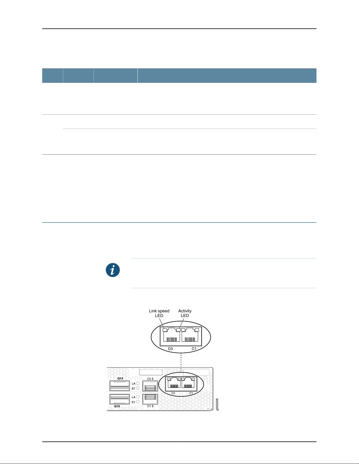
g050208
Activity
LED
Link speed
LED
QFX3600 Device Hardware Documentation
Table 7: Chassis Status LEDs in the QFX3600 and QFX3600-I Device (continued)
DescriptionStateColorName
A software error has occurred. Power off the QFX3600 or QFX3600-I device by
followingthe instructions in “PoweringOff a QFX3600 Device”on page 135. Power
on the QFX3600 or QFX3600-I device and monitor the management board LEDs
to ensure that Junos OS boots properly.
The fan trays are operating normally.On steadilyGreenFan
An error has been detected in a fan tray installed on the rear panel of the device.
Replace the fan tray as soon as possible. To maintain proper airflow through the
chassis leave the fan tray installed in the chassis, until you are ready to replace it.
Related
Documentation
BlinkingAmber
BlinkingAmber
Front Panel of a QFX3600 Device on page 19•
• Front Panel of a QFX3600-I Interconnect Device
• Rear Panel of QFX3600 and QFX3600-I Devices on page 21
• Chassis Alarm Messages on a QFX3500 Device
Management Port LEDs in the QFX3600 and QFX3600-I Device
The RJ-45 management ports labeled C0 and C1 and SFP management ports labeled
C0S and C1S in a QFX3600 or QFX3600-I device have two LEDs that indicate link speed
and activity.
NOTE: On the SFP management ports, LA denotes activity, and ST denotes
speed.
Figure 7: LEDs on the Management Ports on a QFX3600 or QFX3600-I
Device
Copyright © 2017, Juniper Networks, Inc.24
Page 45

Chapter 2: Chassis Components and Descriptions
Table 8 on page 25 describes the management port LEDs.
Table 8: Management Port LEDs in a QFX3600 or QFX3600-I Device
DescriptionStateColorLED
The port is not active.OffUnlitLink speed
1-Gbps link is established.On steadilyGreen
Related
Documentation
On steadilyAmber
• Front Panel of a QFX3600 Device on page 19
• Front Panel of a QFX3600-I Interconnect Device
• Connecting a QFX3600 Device to a Network for Out-of-Band Management
10/100-Mbps link is established.
NOTE: The SFP management ports (C0S and C1S) do not
support 10-Mbps or 100-Mbps speeds.
There is no activity on the link.OffUnlitActivity
There is activity on the link.FlickeringGreen
25Copyright © 2017, Juniper Networks, Inc.
Page 46

QFX3600 Device Hardware Documentation
Copyright © 2017, Juniper Networks, Inc.26
Page 47

CHAPTER 3
g050205
1 2
Cooling System and Airflow
•
Cooling System and Airflow for QFX3600 and QFX3600-I Devices on page 27
•
Fan Tray LED on a QFX3600 or QFX3600-I Device on page 30
Cooling System and Airflow for QFX3600 and QFX3600-I Devices
The cooling systemin QFX3600and QFX3600-I devices consistof three field-replaceable
unit (FRU) fan trays with two fan modules each (see Figure 8 on page 27). In addition,
the power supplies have internal fans to cool themselves.
Figure 8: Fan Tray for QFX3600 and QFX3600-I Devices
The fan tray provides FRU-to-port or port-to-FRU airflow depending on the SKU you
purchase. Table 9 on page 28 lists the different QFX3600 and QFX3600-I SKUs and
their direction of airflow.
NOTE: In QFX Series device model names, AFI, or airflow in, describes
FRU--to-port airflow. AFO, or airflow out, describes port-to-FRU airflow.
NOTE: The rear panel of the device where the power supplies and fan trays
are located is the FRU side of the device.
27Copyright © 2017, Juniper Networks, Inc.
Page 48

g050206
FRUs
Ports
QFX3600 Device Hardware Documentation
Table 9: Airflow Direction in QFX3600 and QFX3600-I Device Models
Direction of AirflowModel
FRU-to-portQFX3600-16Q-AFI
Port-to-FRUQFX3600-16Q-AFO
FRU-to-portQFX3600-I-16Q-AFI
Port-to-FRUQFX3600-I-16Q-AFO
In QFX3600 and QFX3600-I device models that have FRU--to-port airflow,the air intake
to cool the chassis is locatedon the rear panel of the chassis, where the FRUs are installed.
Air is pulled into the chassis and pushed away from the fan trays. Hot air exhausts from
the rear of the chassis, where the ports are located. See Figure 9 on page 28.
Figure 9: FRU-Side-to-Port-Side Airflow Through the QFX3600 and
QFX3600-I Chassis
In QFX3600 and QFX3600-I device models that have port-to-FRU airflow, the air intake
to cool the chassis is located on the front panel of the chassis, the side with access and
uplink ports. Air is pulled into the chassis and pulled through the fan trays.Hot air exhausts
from the front of the chassis, where the FRUs are installed. See Figure 10 on page 29.
Copyright © 2017, Juniper Networks, Inc.28
Page 49

g050207
FRUs
Ports
Chapter 3: Cooling System and Airflow
Figure 10: Port-to-FRU Airflow Through the QFX3600 and QFX3600-I
Chassis
Each airflow type requires specific power supplies and fan trays that have fan modules
oriented in the proper direction. The fan trays are designed so that they can only be
inserted into the device model that supports the same airflow type. The power supplies
have labels and arrows on the handles that depict the direction of airflow (see
Figure11 on page29). The label AFI denotes FRU-to-port airflow.AFO denotesport-to-FRU
airflow.
CAUTION: Verify that the direction of the arrow on the power supply handle
matches the direction of airflow in the chassis. See Table 9 on page 28 to
determine your model’s airflow direction.
Figure 11: Label Identifying Airflow Direction on Power Supply Handle
Table 10 on page 30 lists QFX3600 and QFX3600-I device FRUs and their direction of
airflow.
29Copyright © 2017, Juniper Networks, Inc.
Page 50

QFX3600 Device Hardware Documentation
Table 10: Airflow Direction in QFX3600 and QFX3600-I SKUs
Direction of AirflowPart NumberFRU
FRU-side-to-port-sideQFXC01-FANBIFan tray
Port-side-to-FRU-sideQFXC01-FANBO
AC power supply
Documentation
Related
•
JPSU-650W-AC-AFI
•
QFXC01-PWRACI-650A
FRU-side-to-port-side
Port-side-to-FRU-sideJPSU-650W-AC-AFO
FRU-side-to-port-sideJPSU-650W-DC-AFIDC power supply
Port-side-to-FRU-sideJPSU-650W-DC-AFO
The chassis includes a fan speed-control system. Under normal operating conditions,
fans operate at reduced speed to reduce noise and power consumption.
Temperature sensors in the chassis monitor the temperature within the chassis. The
system raises an alarm if a fan fails or if the temperature inside the chassis rises above
permitted levels. If the temperature inside the chassis rises above the threshold, the
device shuts down automatically. You can see the status of fans and the temperature
remotely through the CLI by issuing the operational mode command show chassis
environment.
You cannot replace a single fan module. If one or more fan modules fail, you must replace
the entire fan tray.
Field-Replaceable Units for QFX3600 and QFX3600-I Devices on page 18•
• Rear Panel of QFX3600 and QFX3600-I Devices on page 21
• Prevention of Electrostatic Discharge Damage on page 200
• Installing a Fan Tray in a QFX3600 or QFX3600-I Device on page 118
• Removing a Fan Tray from a QFX3600 or QFX3600-I Device on page 119
• Fan Tray LED on a QFX3600 or QFX3600-I Device on page 30
Fan Tray LED on a QFX3600 or QFX3600-I Device
Figure 12 on page 31 shows the location of the LED on the fan tray.
Copyright © 2017, Juniper Networks, Inc.30
Page 51

g050205
1 2
Table 11: Fan Tray LED
Chapter 3: Cooling System and Airflow
Figure 12: Fan Tray
2—1— LEDHandle
Table 11 on page 31 describes the function of the fan tray LED.
DescriptionStateColorName
Related
Documentation
The fan tray is operating normally.On steadilyGreenFan
BlinkingAmber
• Cooling System and Airflow for QFX3600 and QFX3600-I Devices on page 27
• Installing a Fan Tray in a QFX3600 or QFX3600-I Device on page 118
• Removing a Fan Tray from a QFX3600 or QFX3600-I Device on page 119
An error has been detected in the fan tray.Replacethe fan tray as soon
as possible. To maintain proper airflow through the chassis, leave the
fan tray installed in the chassis until you are ready to replace it.
31Copyright © 2017, Juniper Networks, Inc.
Page 52

QFX3600 Device Hardware Documentation
Copyright © 2017, Juniper Networks, Inc.32
Page 53

CHAPTER 4
g050002
Handle
Ejector
lever
AC appliance
inlet
Cord retainer
Power Supplies
•
AC Power Supply for a QFX3500, QFX3600, or QFX3600-I Device on page 33
•
DC Power Supply for a QFX3500, QFX3600, or QFX3600-I Device on page 35
•
AC Power Supply LEDs on a QFX3500, QFX3600, or QFX3600-I Device on page 37
•
DC Power Supply LEDs on a QFX3500, QFX3600, or QFX3600-I Device on page 38
AC Power Supply for a QFX3500, QFX3600, or QFX3600-I Device
The power supplies in QFX3500, QFX3600, and QFX3600-I devices (see
Figure 13 on page 33) are hot-removable and hot-insertable field-replaceable units
(FRUs) that you can install on the front panel without powering off the device or disrupting
the switching function.
The AC power supply in QFX3500, QFX3600, and QFX3600-I devices is 650 W.
Figure 13: AC PowerSupply in QFX3500, QFX3600, or QFX3600-IDevices
Thepower supply providesFRU-to-portor port-to-FRUairflowdepending on the product
SKU you purchase. On legacy switches, or switches with an LCD, this airflow is called
back-to-front and front-to-back. The power supplies either have labels on the handles
that indicate the direction of the airflow or they have color-coded handles with a fan
icon. See Figure 15 on page 34 for an example of the power supply with the fan icon. A
power supply with a blue handle denotes FRU-to-port airflow; a power supply with a
gold-colored handle denotes port-to-FRU airflow.
33Copyright © 2017, Juniper Networks, Inc.
Page 54

QFX3600 Device Hardware Documentation
Figure 14: An Arrow Icon and AFI Label Identifying Airflow Direction on
Power Supply Handle
Figure 15: A Fan Icon Identifying Airflow Direction on PowerSupply Handle
CAUTION: Verifythat the direction of the airflow on the power supply handle
matchesthe directionof airflowin the chassis.Ensure thateach powersupply
you install in the chassis has the same airflow direction. If you install power
supplies with two different airflow directions, Junos OS raises an alarm, and
the status (OK/!) LED blinks amber.
Table 12 on page 34 shows the different power supplies and their direction of airflow.
Table 12: Airfow Direction in QFX3500, QFX3600, or QFX3600-I AC Power Supplies
Direction of AirflowModel
•
JPSU-650W-AC-AFI
•
QFXC01-PWRACI-650A
Related
Documentation
To avoid electrical injury, carefully follow instructions in “Connecting AC Power to a
QFX3500, QFX3600, or QFX3600-I Device” on page 83.
AC Power Cord Specifications for a QFX Series Device on page 52•
• AC Power Supply LEDs on a QFX3500, QFX3600, or QFX3600-I Device on page 37
FRU-to-port
Port-to-FRUJPSU-650W-AC-AFO
Copyright © 2017, Juniper Networks, Inc.34
Page 55

• Front Panel of a QFX3500 Device
• Field-Replaceable Units in a QFX3500 Device
• AC Power Specifications for a QFX3500 Device
• Prevention of Electrostatic Discharge Damage on page 200
DC Power Supply for a QFX3500, QFX3600, or QFX3600-I Device
The power supplies in a QFX3500, QFX3600, and QFX3600-I device (see
Figure 16 on page 35 and Figure 17 on page 36) are hot-removable and hot-insertable
field-replaceable units (FRUs) that you can install in the device without powering off the
device or disrupting the switching function.
The DC power supply in QFX3500, QFX3600, and QFX3600-I devices is 650 W.
NOTE: The V+ terminals are referredto as +RTN and V–terminals are referred
to as –48 V in “DC Power Wiring Sequence Warning” on page 209 and “DC
Power Electrical Safety Guidelines for Switches” on page 204.
Chapter 4: Power Supplies
Figure 16: DC Power Supply for a QFX3500, QFX3600, or QFX3600-I
Device
3—1— Ejector leverHandle
2—Terminal block
35Copyright © 2017, Juniper Networks, Inc.
Page 56

g050211
1
678
5
2
3
4
QFX3600 Device Hardware Documentation
Figure 17: DC Power Supply Faceplate
5—1— ESD grounding pointShunt positive input terminals
6—2— Fault LEDShunt negative input terminals
7—3— Output LEDTerminal block
8—4— Input LEDEjector lever
CAUTION: The V+ terminals are shunted internally together, as are the V-
terminals. The same polarity terminal can be wired together from the same
source to provide an additional current path in a higher power chassis. Do
not connect the terminals to different sources.
The power supply provides FRU-to-port or port-to-FRU airflow depending on the SKU
you purchase. The power supplies have labels and arrows on the handles that depict the
direction of airflow (see Figure 18 on page 37). The label AFI denotes FRU-to-port airflow.
AFO denotes port-to FRU airflow.
Copyright © 2017, Juniper Networks, Inc.36
Page 57

Chapter 4: Power Supplies
Figure 18: Label Identifying Airflow Direction on Power Supply Handle
1— Airflow in indicator
CAUTION: Verify that the airflow direction of the power supply handle
matchesthe directionof airflowin the chassis.Ensure thateach powersupply
you install in the chassis has the same airflow direction. If you install power
supplies with two different airflow directions, Junos OS raises an alarm, and
the status (OK/!) LED blinks amber.
Table 13 on page 37 shows the different power supplies and their direction of airflow.
Table 13: Airflow Direction in QFX3500, QFX3600, and QFX3600-I Device DC Power Supplies
Direction of AirflowModel
FRU-to-portJPSU-650W-DC-AFI
Port-to-FRUJPSU-650W-DC-AFO
To avoid electrical injury, carefully follow instructions in “Connecting DC Power to a
QFX3500, QFX3600, or QFX3600-I Device” on page 86.
Related
Documentation
DC Power Supply LEDs on a QFX3500, QFX3600, or QFX3600-I Device on page 38•
• DC Power Specifications for a QFX3500 Device
• DC Power Specifications for a QFX3600 or QFX3600-I Device on page 53
AC Power Supply LEDs on a QFX3500, QFX3600, or QFX3600-I Device
Figure 19 on page 38 shows the location of the LEDs on the power supply.
37Copyright © 2017, Juniper Networks, Inc.
Page 58

g050008
AC OK
DC OK
Fault
QFX3600 Device Hardware Documentation
Figure19: ACPowerSupply LEDs on a QFX3500, QFX3600,or QFX3600-I
Device
Table 14 on page 38 describes the LEDs on the AC power supplies.
Table 14: AC Power Supply LEDs on a QFX3500, QFX3600, or QFX3600-I Device
DescriptionStateColorLED
Related
Documentation
OffUnlitAC OK
OffUnlitDC OK
On steadilyAmberFault
The power supply is disconnected from power, or power is not coming
into the power supply.
Power is coming into the power supply.On steadilyGreen
The power supply is disconnected from power, or the power supply is
not sending out power correctly.
The power supply is sending out power correctly.On steadilyGreen
An error has been detected in the power supply. Replace the power
supply as soon as possible. To maintain proper airflow through the
chassis, leave the power supply installed in the chassis until you are
ready to replace it.
NOTE: If the AC OK LED and the DC OK LED are unlit, either the AC power
cord is not installed properly or the power supply fuse has failed. If the AC
OK LED is lit and the DC OK LED is unlit, the AC power supply is installed
properly, but the power supply has an internal failure.
AC Power Supply for a QFX3500, QFX3600, or QFX3600-I Device on page 33•
• Connecting AC Power to a QFX3500, QFX3600, or QFX3600-I Device on page 83
DC Power Supply LEDs on a QFX3500, QFX3600, or QFX3600-I Device
Figure 20 on page 39 shows the location of the LEDs on the DC power supply.
Copyright © 2017, Juniper Networks, Inc.38
Page 59

g050211
1
678
5
2
3
4
Chapter 4: Power Supplies
Figure 20: DC Power Supply Faceplate on a QFX3500, QFX3600, or
QFX3600-I Device
5—1— ESD grounding pointShunt positive input terminals
6—2— Fault LEDShunt negative input terminals
7—3— Output LEDTerminal block
8—4— Input LEDEjector lever
CAUTION: The V+ terminals are shunted internally together, as are the V-
terminals. The same polarity terminal can be wired together from the same
source to provide an additional current path in a higher power chassis. Do
not connect the terminals to different sources.
Table 15 on page 39 describes the LEDs on the DC power supplies.
Table 15: DC Power Supply LEDs on a QFX3500, QFX3600, or QFX3600-I Device
DescriptionStateColorName
OffUnlitInput
OffUnlitOutput
The power supply is disconnected from power,
or power is not coming into the power supply.
Power is coming into the power supply.On steadilyGreen
The power supply is disconnected from power,
or the power supply is not sending out power
correctly.
The power supply is sending out power correctly.On steadilyGreen
39Copyright © 2017, Juniper Networks, Inc.
Page 60

QFX3600 Device Hardware Documentation
Table 15: DC Power Supply LEDs on a QFX3500, QFX3600, or QFX3600-I Device (continued)
DescriptionStateColorName
Related
Documentation
On steadilyAmberFault
• DC Power Supply for a QFX3500, QFX3600, or QFX3600-I Device on page 35
• Connecting DC Power to a QFX3500, QFX3600, or QFX3600-I Device on page 86
An error has been detected in the power supply.
Replace the power supply as soon as possible.
To maintain proper airflow through the chassis,
leave the power supply installed in the chassis
until you are ready to replace it.
Copyright © 2017, Juniper Networks, Inc.40
Page 61

PART 2
Site Planning, Preparation, and
Specifications
•
Preparation Overview on page 43
•
Power Specifications and Requirements on page 51
•
Transceiver and Cable Specifications on page 55
•
Pinout Specifications on page 65
41Copyright © 2017, Juniper Networks, Inc.
Page 62

QFX3600 Device Hardware Documentation
Copyright © 2017, Juniper Networks, Inc.42
Page 63

CHAPTER 5
Preparation Overview
•
Site Preparation Checklist for a QFX3600 or QFX3600-I Device on page 43
•
Environmental Requirements and Specifications for QFX3600 and QFX3600-I
Devices on page 44
•
General Site Guidelines on page 45
•
Site Electrical Wiring Guidelines on page 46
•
Rack Requirements for a QFX3600 or QFX3600-I Device on page 46
•
Cabinet Requirements for a QFX3600 or QFX3600-I Device on page 48
•
Clearance Requirements for Airflow and Hardware Maintenance for a QFX3600 or
QFX3600-I Device on page 49
Site Preparation Checklist for a QFX3600 or QFX3600-I Device
The checklist in Table 16 on page 43 summarizes the tasks you need to perform when
preparing a site for QFX3600 or QFX3600-I device installation.
Table 16: Site Preparation Checklist
Environment
Verify that environmental factors such as
temperature and humidity do not exceed
device tolerances.
Power
Measure distance between external power
sources and device installation site.
Calculate the power consumption and
requirements.
Rack or Cabinet
DatePerformed ByFor More InformationItem or Task
“Environmental Requirements and
Specifications for QFX3600 and
QFX3600-I Devices” on page 44
“AC PowerSpecificationsfor a QFX3600
or QFX3600-I Device” on page 51
“DC Power Specificationsfor a QFX3600
or QFX3600-I Device” on page 53
43Copyright © 2017, Juniper Networks, Inc.
Page 64

QFX3600 Device Hardware Documentation
Table 16: Site Preparation Checklist (continued)
DatePerformed ByFor More InformationItem or Task
Verify that your rack or cabinet meets the
minimum requirements for the installation
of the switch.
Plan rack or cabinet location, including
required space clearances.
Secure the rack or cabinet to the floor and
building structure.
Cables
Acquire cables and connectors:
•
Determine the number of cables needed
based on your planned configuration.
•
Review the maximum distance allowed
foreach cable. Choose the length of cable
based on the distance between the
hardware components being connected.
Plan the cable routing and management.
Related
Documentation
General Safety Guidelines and Warnings on page 171•
• General Site Guidelines on page 45
“Rack Requirements for a QFX3600 or
QFX3600-I Device” on page 46
“Cabinet Requirements for a QFX3600
or QFX3600-I Device” on page 48
“ClearanceRequirements for Airflowand
Hardware Maintenance for a QFX3600
or QFX3600-I Device” on page 49
“Determining Interface Support for the
QFX3600 Device” on page 55
Determining Transceiver Support for
QFabric Systems
• Installing and Connecting a QFX3600 or QFX3600-I Device on page 71
EnvironmentalRequirements and Specificationsfor QFX3600 and QFX3600-I Devices
The QFX3600 and QFX3600-I devices must be installed in a rack or cabinet housed in
a dry, clean, well-ventilated, and temperature-controlled environment.
Follow these environmental guidelines:
•
The site must be as dust-free as possible, because dust can clog air intake vents and
filters, reducing the efficiency of the device cooling system.
•
Maintain ambient airflow for normal device operation. If the airflow is blocked or
restricted, or if the intake air is too warm, the device might overheat, leading to the
device temperature monitor shutting down the device to protect the hardware
components.
Table 17 on page 45 provides the required environmental conditions for normal device
operation.
Copyright © 2017, Juniper Networks, Inc.44
Page 65

Table 17: QFX3600 and QFX3600-I Device Environmental Tolerances
ToleranceDescription
No performance degradation to 10,000 feet (3048 meters)Altitude
Normal operation ensured in relative humidity range of 5% through 85%, noncondensingRelative humidity
•
Temperature
Normal operation ensured in temperature range of 32° F through 104° F (0° C through 40° C)
•
Short-term operation ensured in temperature range of 23° F through 131° F (–5° C through
55° C)
NOTE: As defined in NEBS GR-63-CORE, Issue 3, short-term events can be up to 96 hours in
duration but not more than 15 days per year.
•
Nonoperatingstoragetemperature in shipping container: –40° F through158° F (–40° C through
70° C)
Designed to comply with Zone 4 earthquake requirements per NEBS GR-63-CORE, Issue 3.Seismic
Chapter 5: Preparation Overview
Related
Documentation
Clearance Requirements for Airflow and Hardware Maintenance for a QFX3600 or
•
QFX3600-I Device on page 49
• Installing and Connecting a QFX3600 or QFX3600-I Device on page 71
General Site Guidelines
Efficient device operation requires proper site planning and maintenance and proper
layout of the equipment, rack or cabinet (if used), and wiring closet.
To plan and create an acceptable operating environment for your device and prevent
environmentally caused equipment failures:
•
Keep the area around the chassis free from dust and conductive material, such as
metal flakes.
•
Followprescribed airflow guidelines to ensure that the cooling systemfunctions properly
and that exhaust from other equipment does not blow into the intake vents of the
device.
NOTE: Install QFX Series devices only in restricted areas, such as dedicated
equipment rooms and equipment closets, in accordance with Articles 110-16,
110-17, and 110-18 of the National Electrical Code, ANSI/NFPA 70.
•
Follow the prescribed electrostatic discharge (ESD) prevention procedures to prevent
damaging the equipment. Static discharge can cause components to fail completely
or intermittently over time.
•
Install the device in a secure area, so that only authorized personnel can access the
device.
45Copyright © 2017, Juniper Networks, Inc.
Page 66

QFX3600 Device Hardware Documentation
Related
Prevention of Electrostatic Discharge Damage on page 200•
Documentation
Site Electrical Wiring Guidelines
Table 18 on page 46 describes the factorsyou must consider while planning the electrical
wiring at your site.
WARNING: It is particularly important to provide a properly grounded and
shielded environment and to use electrical surge-suppression devices.
Table 18: Site Electrical Wiring Guidelines
GuidelinesSite Wiring Factor
Signaling limitations
If your site experiences any of the following problems, consult experts in electrical surge
suppression and shielding:
•
Improperly installed wires cause radio frequency interference (RFI).
•
Damage from lightning strikes occurs when wires exceed recommended distances or pass
between buildings.
•
Electromagnetic pulses (EMPs) caused by lightning damage unshielded conductors and
electronic devices.
Radio frequency
interference
Electromagnetic
compatibility
Related
Documentation
To reduce or eliminate RFI from your site wiring, do the following:
•
Use a twisted-pair cable with a good distribution of grounding conductors.
•
If you must exceed the recommended distances, use a high-quality twisted-pair cable with
one ground conductor for each data signal when applicable.
If your site is susceptible to problems with electromagnetic compatibility (EMC), particularly from
lightning or radio transmitters, seek expert advice.
Some of the problems caused by strong sources of electromagnetic interference (EMI) are:
•
Destruction of the signal drivers and receivers in the device
•
Electrical hazards as a result of power surges conducted over the lines into the equipment
General Safety Guidelines and Warnings on page 171•
• General Electrical Safety Guidelines and Warnings on page 199
• Prevention of Electrostatic Discharge Damage on page 200
Rack Requirements for a QFX3600 or QFX3600-I Device
QFX3600 and QFX3600-I devices are designed to be installed on two-post racks or
four-post racks.
Rack requirements consist of:
Copyright © 2017, Juniper Networks, Inc.46
Page 67

•
Rack type
•
Mounting bracket hole spacing
•
Rack size and strength
•
Rack connection to the building structure
Table 19 on page 47 provides the rack requirements and specifications for a QFX3600
or QFX3600-I device.
Table 19: Rack Requirements for a QFX3600 or QFX3600-I Device
GuidelinesRack Requirement
Chapter 5: Preparation Overview
Rack type
Mounting bracket hole
spacing
Rack size and strength
Rack connection to
building structure
Use a two-post or a four-post rack. You can mount the switch on any two-post or four-post rack
that provides bracket holes or hole patterns spaced at 1 U (1.75 in./4.45 cm) increments and that
meets the size and strength requirements to support the weight.
A U is the standard rack unit defined in Cabinets, Racks, Panels, and Associated Equipment (document
number EIA-310–D) published by the Electronics Industry Association (http://www.eia.org).
The holes in the mounting brackets are spaced at 1 U (1.75 in. or 4.45 cm), so that the switch can
be mounted in any rack that provides holes spaced at that distance.
•
Ensure that the rack complies with the standards for a 19-in. rack as defined in Cabinets, Racks,
Panels, and Associated Equipment (document number EIA-310–D) published by the Electronics
Industry Association.
•
Ensure that the rack rails are spaced widely enough to accommodate the device chassis’ external
dimensions. The outer edges of the mounting brackets extend the width to 19.2 in. (48.8 cm).
•
On four-post racks, the front and rear rack rails must be spaced between 19.3 in. (49 cm) and
36 in. (91.4 cm) front-to-back.
•
The rack must be strong enough to support the weight of the device.
•
Ensure that the spacing of rails and adjacent racks allows for proper clearance around the device
and rack.
•
Secure the rack to the building structure.
•
If earthquakes are a possibility in your geographical area, secure the rack to the floor.
•
Secure the rack to the ceiling brackets as well as wall or floor brackets for maximum stability.
The following types of mounting brackets are supplied with each switch:
•
One pair of mounting brackets for front-mounting or rear-mounting the switch on two
posts of a rack
•
One pair of mounting brackets for mid-mounting the switch (front or rear facing) on
two posts of a rack
•
One pair of fixed railmounting bracketsfor front-mounting or rear-mounting the switch
on four posts of a rack
•
One pair of adjustable rail mounting brackets for front-mounting or rear-mounting the
switch on four posts of a rack
47Copyright © 2017, Juniper Networks, Inc.
Page 68

QFX3600 Device Hardware Documentation
Related
Documentation
Chassis Physical Specifications for QFX3600 and QFX3600-I Devices on page 17•
• Rack-Mounting and Cabinet-Mounting Warnings on page 182
• Clearance Requirements for Airflow and Hardware Maintenance for a QFX3600 or
QFX3600-I Device on page 49
• Mounting a QFX3600 or QFX3600-I Device on Four Posts in a Rack or Cabinet on
page 75
• Mounting a QFX3600 or QFX3600-I Device on Two Posts in a Rack or Cabinet on
page 73
Cabinet Requirements for a QFX3600 or QFX3600-I Device
You can mount a QFX3600 or QFX3600-I device in a cabinet that contains a four-post
19-in. rack as defined in Cabinets, Racks, Panels, and Associated Equipment (document
number EIA-310-D) published by the former Electronics Industry Association.
Cabinet requirements consist of:
•
Cabinet size and clearance
•
Cabinet airflow requirements
Table 20 on page 48 provides the cabinetrequirements and specifications for a QFX3600
or QFX3600-I device.
Table 20: Cabinet Requirements for a QFX3600 or QFX3600-I Device
GuidelinesCabinet Requirement
Cabinet size and
clearance
Cabinet airflow
requirements
Related
Documentation
The minimum cabinet size for accommodating a QFX3600 device is 28 in. (71.1 cm) deep. Large
cabinets improve airflow and reduce the chance of overheating.
When you mount the device in a cabinet, ensure that ventilation through the cabinet is sufficient to
prevent overheating.
•
Ensure that the cool air supply you provide through the cabinet adequately dissipates the thermal
output of the device (or devices).
•
Ensure that the cabinet allows the chassis hot exhaust air to exit the cabinet without recirculating
into the device. An open cabinet (without a top or doors) that employs hot air exhaust extraction
from the top allows the best airflow through the chassis. If the cabinet contains a top or doors,
perforations in these elements assist with removing the hot air exhaust.
•
The device fans exhaust hot air through the rear of the chassis. Install the device in the cabinet in
a way that maximizes the open space on the fan tray side of the chassis. This maximizes the
clearance for critical airflow.
•
Route and dress all cables to minimize the blockage of airflow to and from the chassis.
•
Ensure that the spacing of rails and adjacent cabinets allows for the proper clearance around the
device and cabinet.
Clearance Requirements for Airflow and Hardware Maintenance for a QFX3600 or
•
QFX3600-I Device on page 49
Copyright © 2017, Juniper Networks, Inc.48
Page 69

FRUs
Ports
g050212
16.9 in.
(42.9 cm)
19.2 in.
(48.8 cm)
Mounting bracket
Clearance required
for maintenance
24 in. (60.9 cm)
19.4 in.
(49.2 cm)
Clearance required
for maintenance
24 in. (60.9 cm)
Chapter 5: Preparation Overview
• Rack Requirements for a QFX3600 or QFX3600-I Device on page 46
• Mounting a QFX3600 or QFX3600-I Device on Four Posts in a Rack or Cabinet on
page 75
• Mounting a QFX3600 or QFX3600-I Device on Two Posts in a Rack or Cabinet on
page 73
Clearance Requirements for Airflow and Hardware Maintenance for a QFX3600 or QFX3600-I Device
When planning the site for installing a QFX3600 or QFX3600-I device, you must allow
sufficient clearance around the installed device (see Figure 21 on page 49).
Figure 21: ClearanceRequirements for Airflow and Hardware Maintenance
for a QFX3600 or QFX3600-I Device
Related
Documentation
•
For the cooling system to function properly, the airflow around the chassis must be
unrestricted. See “Cooling System and Airflow for QFX3600 and QFX3600-I Devices”
on page 27 for more information about the airflow through the chassis.
•
If you are mounting a QFX3600 or QFX3600-I device in a rack or cabinet with other
equipment, ensure that the exhaust from other equipment does not blow into the
intake vents of the chassis.
•
Leave at least 24 in. (61 cm) both in front of and behind the QFX3600 or QFX3600-I
device. For service personnel to remove and install hardware components, you must
leave adequate space at the front and back of the device. NEBS GR-63 recommends
that you allow at least 30 in. (76.2 cm) in front of the rack or cabinet and 24 in. (61 cm)
behind the rack or cabinet.
• Rack Requirements for a QFX3600 or QFX3600-I Device on page 46
49Copyright © 2017, Juniper Networks, Inc.
Page 70

QFX3600 Device Hardware Documentation
• Cabinet Requirements for a QFX3600 or QFX3600-I Device on page 48
• General Site Guidelines on page 45
• Rack-Mounting and Cabinet-Mounting Warnings on page 182
Copyright © 2017, Juniper Networks, Inc.50
Page 71

CHAPTER 6
Power Specifications and Requirements
•
AC Power Specifications for a QFX3600 or QFX3600-I Device on page 51
•
AC Power Cord Specifications for a QFX Series Device on page 52
•
DC Power Specifications for a QFX3600 or QFX3600-I Device on page 53
•
Grounding Cable and Lug Specifications for QFX3600 and QFX3600-I
Devices on page 53
AC Power Specifications for a QFX3600 or QFX3600-I Device
Table 21 on page 51 describes the AC power specifications for a QFX3600 or QFX3600-I
device.
Table 21: AC Power Specifications for a QFX3600 or QFX3600-I Device
SpecificationItem
AC input voltage
AC input current rating
Related
Documentation
Operating range:
•
100–240 VAC
50–60 HzAC input line frequency
•
4 A at 100VAC
•
2 A at 240 VAC
255 WTypical power consumption
345 WMaximum power consumption
AC Power Cord Specifications for a QFX Series Device on page 52•
• AC Power Supply for a QFX3500, QFX3600, or QFX3600-I Device on page 33
• General Safety Guidelines and Warnings on page 171
• General Electrical Safety Guidelines and Warnings on page 199
51Copyright © 2017, Juniper Networks, Inc.
Page 72

g021274
QFX3600 Device Hardware Documentation
AC Power Cord Specifications for a QFX Series Device
Detachable AC power cords are shipped with the chassis, if you include them as part of
your order. The coupler is type C13 as described by International Electrotechnical
Commission (IEC) standard 60320. The plug at the male end of the power cord fits into
the power source outlet that is standard for your geographical location.
NOTE: In North America, AC power cords must not exceed 14.75 feet
(approximately4.5 meters)in length,to complywith NationalElectricalCode
(NEC) Sections400-8 (NFPA75, 5-2.2) and 210-52, and Canadian Electrical
Code (CEC) Section 4-010(3). The cords that can be ordered for the QFX
Series switches are in compliance.
Table 22 on page 52 lists AC power cord specifications provided for each country or
region.
Table 22: AC Power Cord Specifications
Switzerland, and United
Kingdom)
250 VAC, 10 A, 50 HzSwitzerland
GraphicJuniper Model NumberPlug StandardsElectrical SpecificationsCountry/Region
CG_CBL-C13-06-AUAS/NZ 3109-1996250 VAC, 10 A, 50 HzAustralia
CG_CBL-C13-06-CHGB 1002-1996250 VAC, 10 A, 50 HzChina
CG_CBL-C13-06-EUCEE (7) VII250 VAC, 10 A, 50 HzEurope (except Italy,
CG_CBL-C13-06-ITCEI 23-16/VII250 VAC, 10 A, 50 HzItaly
CG_CBL-C13-06-JPJIS C8303125 VAC, 12 A, 50 Hz or 60 Hz
CG_CBL-C13-06-USCAN/CSA No. 49-92125 VAC, 13 A, 60 HzNorth America
CG_CBL-C13-06-KRKSC 8305; K60884-1250 VAC, 10 A, 60 HzSouth Korea
CG_CBL-C13-06-SZSEV 1011 SEV 1991; EN
60320 C13
CG_CBL-C13-06--UKBS 1363/A250 VAC, 10 A, 50 HzUnited Kingdom
Related
AC Power Supply for a QFX3500, QFX3600, or QFX3600-I Device on page 33•
Documentation
Copyright © 2017, Juniper Networks, Inc.52
Page 73

Chapter 6: Power Specifications and Requirements
• General Safety Guidelines and Warnings on page 171
• General Electrical Safety Guidelines and Warnings on page 199
• Prevention of Electrostatic Discharge Damage on page 200
• AC Power Supply for a QFX5100 Device
• QFX10002 AC Power Specifications
• QFX5200 AC Power Specifications
• QFX5110 AC Power Specifications
DC Power Specifications for a QFX3600 or QFX3600-I Device
Table 23 on page 53 describes the DC power specifications for a QFX3600 or QFX3600-I
device.
Table 23: DC Power Specifications for a QFX3600 or QFX3600-I Device
SpecificationsItem
•
DC input voltage
Documentation
Related
DC Power Supply for a QFX3500, QFX3600, or QFX3600-I Device on page 35•
• DC Power Supply LEDs on a QFX3500, QFX3600, or QFX3600-I Device on page 38
Minimum operating voltage: –40 VDC
•
Nominal operating voltage: –48 VDC
•
Operating voltage range: –40 VDC through –72 VDC
8 A maximum at nominal operating voltage (–48 VDC)DC input current rating
341 WTypical power consumption
252 WMaximum power consumption
Grounding Cable and Lug Specifications for QFX3600 and QFX3600-I Devices
For installations that require a separate grounding conductor to the chassis, the device
must be adequately grounded before power is connected to ensure proper operation
and to meet safety and electromagnetic interference (EMI) requirements. To ground a
QFX3600 or QFX3600-I device, connect a grounding cable to earth ground and then
attach it to the chassis grounding points.
WARNING: The device is pluggable type A equipment installed in a
restricted-access location. It has a separate protective earthing terminal
provided on the chassis in addition to the grounding pin of the power supply
cord. This separate protective earthing terminal must be permanently
53Copyright © 2017, Juniper Networks, Inc.
Page 74

QFX3600 Device Hardware Documentation
Before connecting the device to earth ground, review the following information:
•
The grounding points on the chassis are sized for M5 screws. The grounding points are
spaced at 0.625 in. (15.86 mm). M5 screws with integrated washers are provided in
the accessory kit. You may use a disposable ESD strap to connect to grounding points.
•
The grounding lug required is a Panduit LCD10-10A-L or equivalent. This grounding lug
is provided in the accessory kit. The grounding lug providedaccommodates14–10 AWG
(2–5.3 mm²) stranded wire. You may only use clip-style ESD straps to connect to a
grounding lug.
connectedto earth ground for installationsthat require a separate grounding
conductor to the chassis.
CAUTION: Before device installation begins, a licensed electrician must
attach a cable lug to the grounding cables that you supply. See “Connecting
Earth Ground to QFX3600 or QFX3600-I Devices” on page 82. A cable with
an incorrectly attached lug can damage the device.
Related
Documentation
•
The grounding cable that you provide for a QFX3600 or QFX3600-I device must be
14 AWG (2 mm²), minimum 60° C wire, or as permitted by the local code.
• AC Power Supply for a QFX3500, QFX3600, or QFX3600-I Device on page 33
• Connecting AC Power to a QFX3500, QFX3600, or QFX3600-I Device on page 83
Copyright © 2017, Juniper Networks, Inc.54
Page 75

CHAPTER 7
Transceiver and Cable Specifications
•
Determining Interface Support for the QFX3600 Device on page 55
•
Cable Specifications for QSFP+ and QSFP28 Transceivers on page 56
•
Cable Specifications for Console and Management Connections for the QFX
Series on page 58
•
Understanding QFX Series Fiber-Optic Cable Signal Loss, Attenuation, and
Dispersion on page 59
•
Calculating the Fiber-Optic Cable Power Budget for a QFX Series Device on page 61
•
Calculating the Fiber-Optic Cable Power Margin for a QFX Series Device on page 61
Determining Interface Support for the QFX3600 Device
The QFX3600 device provides 16 QSFP+ ports, which support QSFP+ transceivers and
QSFP+ DAC or DAC breakout cables.
On a QFX3600 Node device in a QFabric system, four ports (labeled Q0 through Q3)
operateas40-Gbps data uplink (fte) ports for uplink connections betweenyour QFX3600
Node device and your Interconnect device. Twelveports (labeled Q4 through Q15) operate
in 10-Gigabit Ethernet (xe) mode to support 48 10-Gigabit Ethernet interfaces for
connections to either endpoint systems or external networks. Optionally, you can choose
to configure ports Q0 through Q7 to operate as 40-Gbps data uplink (fte) ports, and
ports Q2 through Q15 to operate in 10-Gigabit Ethernet (xe) or 40-Gigabit Ethernet (xle)
mode. See Configuring the Port Type on QFX3600 Node Devices for more information.
On a QFX3600 standalone switch, ports Q0 through Q15 operateas 40-Gigabit Ethernet
(xle) ports. Optionally, you can choose to configure ports Q0 through Q15 to operate as
10-Gigabit Ethernet (xe) ports. See “Configuring the Port Type on QFX3600 Standalone
Switches” on page 133 for more information.
NOTE: On a QFX3600 standalone switch, you can either configure up to 63
or 64 10-Gigabit Ethernet ports on ports Q0 through Q15, depending on the
Junos OS releaserunningon the switch. Seethe Channelizing Interfaces topic
for your specific Junos OS release for further details.
55Copyright © 2017, Juniper Networks, Inc.
Page 76

QFX3600 Device Hardware Documentation
You can use SFP transceiverstoconnect the QFX3600 device toa managementnetwork,
or the control plane and management network of a QFabric system. The 1000BASE-SX
Gigabit Ethernet SFP module (QFX-SFP-1GE-SX) is supported in the SFP management
ports labeled C0S and C1S. The QFX3600 device also has two 1000BASE-T RJ-45
management ports (labeled C0 and C1), which can be used to connect the QFX3600
device to a management network, or the control plane and management network of a
QFabric system.
You can find information about the optical transceivers supported on your Juniper device
by using the Hardware Compatibility Tool.In addition to transceiverand connection type,
the optical and cable characteristics–where applicable–are documented for each
transceiver. The HardwareCompatibilityTool enables you to search by product, displaying
all the transceivers supported on that device, or category, by interface speed or type. The
list of supported transceivers for the QFX3600 and QFX3600-I Interconnect device is
located at https://pathfinder.juniper.net/hct/product/#prd=QFX3600.
NOTE: The QSFP+ DAC cables consist of a cable assembly terminated with
QSFP+ transceivers on either end. If you use the QSFP+ DAC cable as the
data plane connection between a QFX3600-I Interconnect device and a
QFX3600or QFX3500Node device,the interfaceis automatically configured
to operate at 40 Gbps. If you use the QSFP+ DAC cable to interconnect a
QFX3600 Node device with another device, the interface is automatically
configured to operate as four 10-Gigabit Ethernet interfaces over one cable.
CAUTION: If you facea problem running a Juniper Networks device that uses
a third-party optic or cable, the Juniper NetworksTechnical Assistance Center
(JTAC) can help you diagnose the source of the problem. Your JTAC engineer
might recommend thatyou check the third-partyoptic or cable and potentially
replaceit with an equivalent Juniper Networks optic or cable that is qualified
for the device.
Related
Documentation
Front Panel of a QFX3600 Device on page 19•
• Rear Panel of QFX3600 and QFX3600-I Devices on page 21
Cable Specifications for QSFP+ and QSFP28 Transceivers
The 40-Gigabit Ethernet QSFP+ and 100-Gigabit Ethernet QSFP28 transceiversthat are
used in QFX Series and EX4600 switches use 12-ribbon multimode fiber crossover cables
with female MPO/UPC connectors. The fiber can be either OM3 or OM4. These cables
are not sold by Juniper Networks.
CAUTION: To maintain agency approvals, use only a properly constructed,
shielded cable.
Copyright © 2017, Juniper Networks, Inc.56
Page 77

Chapter 7: Transceiver and Cable Specifications
TIP: Ensure that you order cables with the correct polarity. Vendors refer to
these crossover cables as key up to key up, latch up to latch up, Type B, or
Method B. If you are using patch panels between two QSFP+ or QSFP28
transceivers,ensure that the properpolarity is maintained through the cable
plant.
Table 24 on page 57 describes the signals on each fiber. Table 25 on page 57 shows the
pin-to-pin connections for proper polarity.
Table 24: QSFP+ and QSFP28 Optical Module Receptacle Pinouts
SignalFiber
Tx0 (Transmit)1
Tx1 (Transmit)2
Tx2 (Transmit)3
Tx3 (Transmit)4
Unused5
Unused6
Unused7
Unused8
Rx3 (Receive)9
Rx2 (Receive)10
Rx1 (Receive)11
Rx0 (Receive)12
Table 25: QSFP+ MPO Fiber-Optic Crossover Cable Pinouts
PinPin
121
112
103
94
57Copyright © 2017, Juniper Networks, Inc.
Page 78

QFX3600 Device Hardware Documentation
Table 25: QSFP+ MPO Fiber-Optic Crossover Cable Pinouts (continued)
PinPin
85
76
67
58
49
310
211
112
Related
Documentation
Determining Interface Support for the QFX3500 Device•
• Determining Interface Support for the QFX3600 Device on page 55
• Determining Interface Support for the QFX5100 Device
• Determining Transceiver Support for the QFX5110
• Determining QFX5200 Optical Interface Support
• Determining QFX10000 Optical Transceiver and Cable Support
Cable Specifications for Console and Management Connections for the QFX Series
Table 26 on page 58 lists the specifications for the cables that connect the QFX Series
to a management device.
NOTE: The QFX Series can be configured with SFP management ports that
support 1000BASE-SX transceivers. See The Hardware Compatibility Tool for
more on the fiber-optic cables required for use with these transceivers.
Table 26: Cable Specifications for Console and Management Connections for the QFX Series
Porton QFX Series
Device
Device
ReceptacleMaximum LengthCable SuppliedCable Specification
RS-232(EIA-232) serial cableConsole port
RJ-45 patch cable and RJ-45 to
DB-9 adapter
Copyright © 2017, Juniper Networks, Inc.58
RJ-457 feet (2.13 meters)One 7-foot (2.13-meter) long
Page 79

Chapter 7: Transceiver and Cable Specifications
Table 26: Cable Specifications for Console and Management Connections for the QFX
Series (continued)
Porton QFX Series
Device
Management port
Related
Documentation
Category 5 cable or
equivalent suitable for
1000BASE-T operation
One 7-foot (2.13-meter) long
RJ-45 patch cable
(100 meters)
Console Port Connector Pinouts for the QFX Series on page 66•
• Management Port Connector Pinouts for the QFX Series
• Connecting a QFX Series Device to a Management Console
• Connecting a QFX3600 Device to a Network for Out-of-Band Management
• Connecting a QFX3500 Device to a Network for Out-of-Band Management
• Connecting a QFX3100 Director Device to a Network for Out-of-Band Management
• Connecting a QFX5100 Device to a Network for Out-of-Band Management
• Connecting a QFX5110 to a Network for Out-of-Band Management
• Connecting a QFX5200 to a Network for Out-of-Band Management
• Connecting a QFX5300 to a Network for Out-of-Band Management
Device
ReceptacleMaximum LengthCable SuppliedCable Specification
RJ-45328 feet
Understanding QFX Series Fiber-Optic Cable Signal Loss, Attenuation, and Dispersion
To determine the power budget and power margin needed for fiber-optic connections,
you need to understand how signal loss, attenuation,and dispersion affect transmission.
The QFX Series uses various types of network cables, including multimode and
single-mode fiber-optic cables.
•
Signal Loss in Multimode and Single-Mode Fiber-Optic Cables on page 59
•
Attenuation and Dispersion in Fiber-Optic Cable on page 60
Signal Loss in Multimode and Single-Mode Fiber-Optic Cables
Multimode fiber is large enough in diameter to allow rays of light to reflect internally
(bounce off the walls of the fiber). Interfaces with multimode optics typically use LEDs
as light sources. However, LEDs are not coherent light sources. They spray varying
wavelengths of light into the multimode fiber, which reflect the light at different angles.
Light rays travel in jagged lines through a multimode fiber, causing signal dispersion.
When light traveling in the fiber core radiates into the fiber cladding (layers of lower
refractive index material in close contact with a core material of higher refractive index),
higher-order mode loss occurs. Together,these factors reduce the transmission distance
of multimode fiber compared to that of single-mode fiber.
Single-mode fiber is so small in diameter that rays of light reflect internally through one
layeronly. Interfaces with single-mode optics use lasers as light sources. Lasers generate
59Copyright © 2017, Juniper Networks, Inc.
Page 80

QFX3600 Device Hardware Documentation
a single wavelength of light, which travelsin a straight line through the single-mode fiber.
Compared to multimode fiber, single-mode fiber has a higher bandwidth and can carry
signals for longer distances. It is consequently more expensive.
For information about the maximum transmission distance and supported wavelength
range for the types of single-mode and multimode fiber-optic cables that are connected
to the QFX Series, see the Hardware Compatibility Tool . Exceeding the maximum
transmission distances can result in significant signal loss, which causes unreliable
transmission.
Attenuation and Dispersion in Fiber-Optic Cable
An optical data link functions correctlyprovided that modulatedlight reachingthe receiver
has enough power to be demodulated correctly. Attenuation is the reduction in strength
of the light signal during transmission. Passive media components such as cables, cable
splices, and connectors cause attenuation. Although attenuation is significantly lower
for optical fiber than for other media, it still occurs in both multimode and single-mode
transmission. An efficient optical data link must transmit enough light to overcome
attenuation.
Dispersion is the spreading of the signal over time. The following two types of dispersion
can affect signal transmission through an optical data link:
•
Chromatic dispersion, which is the spreading of the signal over time caused by the
different speeds of light rays.
•
Modal dispersion, which is the spreading of the signal over time caused by the different
propagation modes in the fiber.
For multimode transmission, modal dispersion, rather than chromatic dispersion or
attenuation, usually limits the maximum bit rate and link length. For single-mode
transmission, modal dispersion is not a factor. However, at higher bit ratesand over longer
distances, chromatic dispersion limits the maximum link length.
An efficient optical data link must have enough light to exceed the minimum power that
the receiver requires to operate within its specifications. In addition, the total dispersion
must be within the limits specified for the type of link in the Telcordia Technologies
document GR-253-CORE (Section 4.3) and International Telecommunications Union
(ITU) document G.957.
When chromatic dispersion is at the maximum allowed, its effect can be considered as
a power penalty in the power budget. The optical power budget must allow for the sum
of component attenuation, power penalties (including those from dispersion), and a
safety margin for unexpected losses.
Related
Documentation
Calculating the Fiber-Optic Cable Power Budget for a QFX Series Device on page 61•
• Calculating the Fiber-Optic Cable Power Margin for a QFX Series Device on page 61
Copyright © 2017, Juniper Networks, Inc.60
Page 81

Chapter 7: Transceiver and Cable Specifications
Calculating the Fiber-Optic Cable Power Budget for a QFX Series Device
Calculate the link's power budget when planning fiber-optic cable layout and distances
to ensure that fiber-optic connections have sufficient power for correct operation. The
powerbudget is the maximum amount of power the link can transmit.When you calculate
the power budget, you use a worst-case analysis to provide a margin of error,even though
all the parts of an actual system do not operate at the worst-case levels.
To calculate the worst-case estimate for the fiber-optic cable power budget (PB) for the
link:
1. Determinevalues for the link's minimum transmitter power (P
) and minimum receiver
T
sensitivity (PR). For example, here, (PT) and (PR) are measuredin decibels, and decibels
are referenced to 1 milliwatt (dBm):
PT= –15 dBm
PR= –28 dBm
NOTE: See the specifications for your transmitter and receiver to find the
minimum transmitter power and minimum receiver sensitivity.
2. Calculate the power budget (P
B
) by subtracting (PR) from (PT):
–15 dBm – (–28 dBm) = 13 dBm
Related
Documentation
Understanding QFX Series Fiber-Optic Cable Signal Loss, Attenuation, and Dispersion
•
on page 59
• Calculating the Fiber-Optic Cable Power Margin for a QFX Series Device on page 61
Calculating the Fiber-Optic Cable Power Margin for a QFX Series Device
Calculate the link's power margin when planning fiber-optic cable layout and distances
to ensure that fiber-optic connections have sufficient signal power to overcome system
losses and still satisfy the minimum input requirements of the receiver for the required
performance level. The power margin (PM) is the amount of power available after
attenuation or link loss (LL) has been subtracted from the power budget (PB).
When you calculate the power margin, you use a worst-case analysis to provide a margin
of error, even though all the parts of an actual system do not operate at worst-case
levels.A powermargin (PM) greater than zero indicatesthat the power budgetis sufficient
to operate the receiver and that it does not exceed the maximum receiver input power.
This means the link will work. A (PM) that is zero or negative indicates insufficient power
to operate the receiver. See the specification for your receiver to find the maximum
receiver input power.
61Copyright © 2017, Juniper Networks, Inc.
Page 82

QFX3600 Device Hardware Documentation
Before you begin to calculate the power margin:
•
Calculate the power budget. See “Calculating the Fiber-Optic Cable Power Budget for
a QFX Series Device” on page 61.
To calculate the worst-case estimate for the power margin (PM) for the link:
1. Determine the maximum value for link loss (LL) by adding estimated values for
applicable link-loss factors; for example, use the sample values for various factors
as provided in Table27 on page 62 (here, the link is 2 km long and multimode, and the
(PB) is 13 dBm).
Table 27: Estimated Values for Factors Causing Link Loss
Sample Link Loss (LL) Calculation ValuesEstimated Link Loss ValueLink-Loss Factor
0.5 dBmMultimode—0.5 dBmHigher-order mode losses
0 dBmSingle-mode—None
Modal and chromatic
dispersion
(CRM)
bandwidth and distance is less
than 500 MHz/km
0.5 dBmConnector
0.5 dBmSplice
Multimode—1 dBm/kmFiber attenuation
Single-mode—0.5 dBm/km
NOTE: For information about the actual amount of signal loss caused by
equipment and other factors, see your vendor documentation for that
equipment.
0 dBmMultimode—None, if product of
0 dBmSingle-mode—None
This example assumes five connectors. Loss for five
connectors: 5 (0.5 dBm) = 2.5 dBm.
This example assumes two splices. Loss for two splices:
2 (0.5 dBm) = 1 dBm.
This example assumes the link is 2 km long. Fiber
attenuation for 2 km: 2 km (1 dBm/km) = 2 dBm.
This example assumes the link is 2 km long. Fiber
attenuation for 2 km: 2 km (0.5 dBm/km) = 1 dBm.
1 dBm1 dBmClock Recovery Module
2. Calculate the (P
PB– LL = P
M
) by subtracting (LL) from (PB):
M
Copyright © 2017, Juniper Networks, Inc.62
Page 83

Chapter 7: Transceiver and Cable Specifications
13 dBm – 0.5 dBm [HOL] – 5 (0.5 dBm) – 2 (0.5 dBm) – 2 km (1.0 dBm/km) – 1 dB
[CRM] = P
13 dBm – 0.5 dBm – 2.5 dBm – 1 dBm – 2 dBm – 1 dBm = P
M
M
PM= 6 dBm
The calculatedpower margin is greaterthan zero,indicating that the link has sufficient
power for transmission. Also, the power margin value does not exceed the maximum
receiverinput power. Refer to the specifications for your receiver to find the maximum
receiver input power.
Related
Documentation
• Understanding QFX Series Fiber-Optic Cable Signal Loss, Attenuation, and Dispersion
on page 59
63Copyright © 2017, Juniper Networks, Inc.
Page 84

QFX3600 Device Hardware Documentation
Copyright © 2017, Juniper Networks, Inc.64
Page 85

CHAPTER 8
Pinout Specifications
•
USB Port Specifications for the QFX Series on page 65
•
Console Port Connector Pinouts for the QFX Series on page 66
•
RJ-45 Management Port Connector Pinout Information on page 67
USB Port Specifications for the QFX Series
The following Juniper Networks USB flash drives have been tested and are officially
supported for the USB port in the QFX Series:
•
RE-USB-1G-S—1-gigabyte (GB) USB flash drive (except QFX3100 Director device)
•
RE-USB-2G-S—2-GB USB flash drive (except QFX3100 Director device)
•
RE-USB-4G-S—4-GB USB flash drive
CAUTION: Any USB memory product not listed as supported for the QFX
Series has not been tested by Juniper Networks. The use of any unsupported
USB memory product could expose your device to unpredictable behavior.
Juniper Networks TechnicalAssistanceCenter (JTAC) can provideonly limited
support for issuesrelatedtounsupported hardware.Westrongly recommend
that you use only supported USB flash drives.
CAUTION: Remove the USB flash drive before upgrading Junos OS or
rebooting a QFX Series device. Failure to do so could expose your device to
unpredictable behavior.
NOTE: Executing the request system snapshot CLI command on a QFX3500
device requires an external USB flash drive with at least 4 GB of free space.
We recommend using the RE-USB-4G-S flash drive.
65Copyright © 2017, Juniper Networks, Inc.
Page 86

QFX3600 Device Hardware Documentation
NOTE: USB flash drives used with the QFX Series device must support
USB 2.0 or later.
Related
Documentation
Creating an Emergency Boot Device on page 163•
• Performing a Recovery Installation Using an Emergency Boot Device
Console Port Connector Pinouts for the QFX Series
The console port (labeled CON, or CONSOLE) is an RS-232 serial interface that uses an
RJ-45 connector to connect to a console management device. The default baud rate for
the console port is 9600 baud.
Table 28 on page 66 provides the pinout information for the RJ-45 console connector.
An RJ-45 cable and RJ-45 to DB-9 adapter are supplied with the QFX Series device.
NOTE: If your laptop or PC does not have a DB-9 male connectorpin and you
want to connect your laptop or PC directly to a QFX Series device, use a
combinationof the RJ-45 cableand RJ-45 to DB-9 adapter supplied with the
device and a USB to DB-9 male adapter. You must provide the USB to DB-9
male adapter.
Table 28: Console Port Connector Pinouts for the QFX Series
DescriptionSignalPin
Related
Documentation
Request to sendRTS Output1
Data terminal readyDTR Output2
Transmit dataTxD Output3
Signal groundSignal Ground4
Signal groundSignal Ground5
Receive dataRxD Input6
Data carrier detectDCD Input7
Clear to sendCTS Input8
Connecting a QFX Series Device to a Management Console•
Copyright © 2017, Juniper Networks, Inc.66
Page 87

RJ-45 Management Port Connector Pinout Information
Table 29 on page 67 provides the pinout information for the RJ-45 connector for the
management port on Juniper Networks devices.
Table 29: RJ-45 Management Port Connector Pinout Information
DescriptionSignalPin
Transmit/receive data pair 1TRP1+1
Transmit/receive data pair 1TRP1-2
Transmit/receive data pair 2TRP2+3
Transmit/receive data pair 3TRP3+4
Transmit/receive data pair 3TRP3-5
Chapter 8: Pinout Specifications
Related
Documentation
Transmit/receive data pair 2TRP2-6
Transmit/receive data pair 4TRP4+7
Transmit/receive data pair 4TRP4-8
• Connecting a Device to a Network for Out-of-Band Management on page 91
67Copyright © 2017, Juniper Networks, Inc.
Page 88

QFX3600 Device Hardware Documentation
Copyright © 2017, Juniper Networks, Inc.68
Page 89

PART 3
Initial Installation and Configuration
•
Unpacking and Mounting the Device on page 71
•
Connecting the QFX3600 Device to Power on page 81
•
Connecting the Device to the Network on page 91
•
Performing Initial Configuration on page 103
69Copyright © 2017, Juniper Networks, Inc.
Page 90

QFX3600 Device Hardware Documentation
Copyright © 2017, Juniper Networks, Inc.70
Page 91

CHAPTER 9
Unpacking and Mounting the Device
•
Installing and Connecting a QFX3600 or QFX3600-I Device on page 71
•
Unpacking a QFX3600 or QFX3600-I Device on page 72
•
Mounting a QFX3600 or QFX3600-I Device on Two Posts in a Rack or
Cabinet on page 73
•
Mounting a QFX3600 or QFX3600-I Device on Four Posts in a Rack or
Cabinet on page 75
Installing and Connecting a QFX3600 or QFX3600-I Device
To install and connect a QFX3600 or QFX3600-I device:
1. Follow the instructions in “Unpacking a QFX3600 or QFX3600-I Device” on page 72.
2. Mount the device by following the instructions appropriate for your site:
•
Mounting a QFX3600 or QFX3600-I Device on Two Posts in a Rack or Cabinet on
page 73
•
Mounting a QFX3600 or QFX3600-I Device on Four Posts in a Rack or Cabinet on
page 75
3. Follow the instructions in “Connecting Earth Ground to QFX3600 or QFX3600-I
Devices” on page 82.
4. Follow the instructions for connecting power as appropriate for your site:
•
Connecting AC Power to a QFX3500, QFX3600, or QFX3600-I Device on page 83
•
Connecting DC Power to a QFX3500, QFX3600, or QFX3600-I Device on page 86
5. Depending on how you will be using the QFX3600 or QFX3600-I device, take one of
the following actions:
•
If you are using the QFX3600 device as a standalone switch, follow the instructions
in “Configuring a QFX3600 Device as a Standalone Switch” on page 103.
•
If you are using the QFX3600 device as a Node device in a QFX3000-G QFabric
system,see QFX3000-G QFabric SystemInstallationOverview for information about
the steps to install and configure your QFX3000-G QFabric system.
71Copyright © 2017, Juniper Networks, Inc.
Page 92

QFX3600 Device Hardware Documentation
•
If you are using the QFX3600 device as a Node device in a QFX3000-M QFabric
system,see QFX3000-M QFabric System Installation Overview for information about
the steps to install and configure your QFX3000-M QFabric system.
•
If you are using the QFX3600-I device as an Interconnect device in a QFX3000-M
QFabric system, see QFX3000-M QFabric System Installation Overview for
information about the steps to install and configure your QFX3000-M QFabric
system.
Related
Documentation
Rack Requirements for a QFX3600 or QFX3600-I Device on page 46•
• Cabinet Requirements for a QFX3600 or QFX3600-I Device on page 48
• Clearance Requirements for Airflow and Hardware Maintenance for a QFX3600 or
QFX3600-I Device on page 49
Unpacking a QFX3600 or QFX3600-I Device
The QFX3600 or QFX3600-I device chassis is a rigid sheet-metal structure that houses
the hardware components. QFX3600and QFX3600-I devicesare shipped in a cardboard
carton, secured with foam packing material. The carton also contains an accessory box
and quick start instructions.
CAUTION: QFX3600and QFX3600-Idevices are maximally protectedinside
the shipping carton. Do not unpack the device until you are ready to begin
installation.
To unpack a QFX3600 or QFX3600-I device:
1. Move the shipping carton to a staging area as close to the installation site as possible,
but where you have enough room to remove the system components.
2. Position the carton so that the arrows are pointing up.
3. Open the top flaps on the shipping carton.
4. Remove the accessory box and verify the contents against the inventory included in
the box. Table 30 on page 73 lists the inventory of components supplied with a
QFX3600 or QFX3600-I device.
5. Pull out the packing material holding the device in place.
6. Verify the chassis components received:
•
Three fan trays
Copyright © 2017, Juniper Networks, Inc.72
Page 93

•
Two power supplies
7. Save the shipping carton and packing materials in case you need to move or ship the
device later.
Table 30: Accessory Kit Part Contents
NOTE: Use only clip-style ESD grounding straps with the chassis grounding lug.
Chapter 9: Unpacking and Mounting the Device
QuantityParts
1Chassis grounding lug
2M5 screws to attach the chassis grounding lug to the protective earth terminal on the chassis
1Electrostatic discharge (ESD) grounding strap
2SFP/SFP+ port dust covers
16QSFP+ port dust covers
1RJ-45 cable and RJ-45 to DB-9 adapter for console port connection
2Mounting brackets for front-mounting in a four-post rack or cabinet
6M4 flat-head screws to attach the brackets for front-mounting in a rack or cabinet
2Rear installation blades for front-mounting in a four-post rack or cabinet
2Mounting brackets for front-mounting in a two-post rack or cabinet
2Mounting brackets for mid-mounting in a two-post rack or cabinet
6M4 pan-head screws to attach the brackets for front-mounting or mid-mounting in a rack or cabinet
Related
Installing and Connecting a QFX3600 or QFX3600-I Device on page 71•
Documentation
Mounting a QFX3600 or QFX3600-I Device on Two Posts in a Rack or Cabinet
You can mid-mount a QFX3600 or QFX3600-I device on two posts of a 19-in. rack or
cabinet by using the mounting brackets provided with the device. (The remainder of this
topic uses “rack” to mean “rack or cabinet.”)
You can also mount the device on four posts of a four-post rack by using the mounting
brackets provided with the device. See “Mounting a QFX3600 or QFX3600-I Device on
Four Posts in a Rack or Cabinet” on page 75.
The holes in the mounting brackets are placed at 1 U (1.75 in., or 4.45 cm.) apart so that
the device can be mounted in any rack that provides holes spaced at that distance.
73Copyright © 2017, Juniper Networks, Inc.
Page 94

QFX3600 Device Hardware Documentation
Before mounting a QFX3600 or QFX3600-I device on two posts in a rack:
•
Ensure you understand how to prevent electrostatic discharge (ESD) damage. See
“Prevention of Electrostatic Discharge Damage” on page 200.
•
Verify that the site meets the requirements described in “Site Preparation Checklist
for a QFX3600 or QFX3600-I Device” on page 43.
•
Place the rack in its permanent location, allowing adequate clearance for airflow and
maintenance, and secure it to the building structure.
•
Read “General Safety Guidelines and Warnings” on page 171, with particular attention
to “Chassis Lifting Guidelines for a QFX3600 or QFX3600-I Device” on page 180.
•
Removethe device from the shipping carton(see “Unpacking a QFX3600 or QFX3600-I
Device” on page 72).
Ensure that you have the following parts and tools available:
•
ESD grounding strap (provided)
•
One pair of mounting brackets depending on how you want to mount the device
(provided)
•
Use the front/rear mounting brackets (part number 540-038579) to front-mount
or rear-mount the device.
•
Use the mid-mounting brackets (part number 540-038665) to mid-mount the
device.
•
6 Phillips 4x6-mm pan-head mounting screws (provided)
•
Four screws to secure the chassis to the rack (not provided)
•
Appropriate screwdriver for the mounting screws (not provided)
NOTE: One person must be available to lift the device while another secures
the device to the rack.
CAUTION: If you are mounting multiple device on a rack, mount a device in
the bottom of the rack first and proceed to mount the rest of the devices
from bottom to top.
To mount the device on two posts in a rack:
1. Attach the ESD grounding strap to your bare wrist and to a site ESD point.
2. Place the device on a flat, stable surface.
Copyright © 2017, Juniper Networks, Inc.74
Page 95

AC
!
DC
g050216
AC
!
DC
Chapter 9: Unpacking and Mounting the Device
3. Align the mid-mounting brackets (part number 540-038665) with the holes on the
side panels of the device chassis, such that the mounting ears are in the center of the
side panels. See Figure 22 on page 75.
4. Insert mounting screws into the aligned holes. Tighten the screws.
5. Have one person grasp both sides of the device, lift the device, and position it in the
rack, aligning the mounting ear holes with the threaded holes in the rack or cabinet
rail. Align the bottom mounting ear hole in both the mounting brackets with a hole in
each rack rail, making sure the chassis is level. See Figure 22 on page 75.
6. Have a second person secure the device to the rack by using the appropriate screws.
Tighten the screws.
7. Ensure that the device chassis is level by verifying that all screws on one side of the
rack are aligned with the screws on the other side.
Figure 22: Mounting the Device on Two Posts in a Rack
Related
Documentation
Rack-Mounting and Cabinet-Mounting Warnings on page 182•
• Connecting Earth Ground to QFX3600 or QFX3600-I Devices on page 82
• Connecting AC Power to a QFX3500, QFX3600, or QFX3600-I Device on page 83
• Connecting DC Power to a QFX3500, QFX3600, or QFX3600-I Device on page 86
Mounting a QFX3600 or QFX3600-I Device on Four Posts in a Rack or Cabinet
You can front-mount or rear-mount a QFX3600 or QFX3600-I device on four posts in a
19-in. rack or cabinet by using the mounting brackets and installation blades provided
with the device. (The remainder of this topic uses “rack” to mean “rack or cabinet.”) The
front and rear rack rails must be spaced between 19.3 in. (49 cm) and 36 in. (91.4 cm)
front to back.
75Copyright © 2017, Juniper Networks, Inc.
Page 96

QFX3600 Device Hardware Documentation
You can also mount the device on two posts of a 19-in. rack or cabinet by using the
mounting brackets provided with the device. See “Mounting a QFX3600 or QFX3600-I
Device on Two Posts in a Rack or Cabinet” on page 73.
The holes in the mounting brackets and installation blades are placed at 1 U (1.75 in., or
4.45cm.) apart so that the device can be mounted in any rack that provides holes spaced
at that distance.
Before you begin mounting a QFX3600 or QFX3600-I device on the rack or cabinet:
•
Ensure you understand how to prevent electrostatic discharge (ESD) damage. See
“Prevention of Electrostatic Discharge Damage” on page 200.
•
Verify that the site meets the requirements described in “Site Preparation Checklist
for a QFX3600 or QFX3600-I Device” on page 43.
•
Place the rack in its permanent location, allowing adequate clearance for airflow and
maintenance, and secure it to the building structure.
•
Read“General Site Guidelines” on page 45, with particular attention to “Chassis Lifting
Guidelines for a QFX3600 or QFX3600-I Device” on page 180.
•
Removethe device from the shipping carton(see “Unpacking a QFX3600 or QFX3600-I
Device” on page 72).
Ensure that you have the following parts and tools available to mount the device on four
posts in a rack:
•
ESD grounding strap (provided).
•
One pair of mounting brackets (part number 540-038596) (provided).
•
One pair of rear installation blades (part number 540-038598). These installation
blades support the rear of the chassis, and must be installed (provided).
•
6 Phillips 4x5-mm flat-head mounting screws (provided).
•
Eight screws to secure the chassis and rear installation blades to the rack (not provided).
•
Appropriate screwdriver for the mounting screws (not provided).
WARNING: QFX3600 and QFX3600-I devices must be supported at all four
corners. Mounting the chassis using only the front brackets damages the
chassis and can result in serious bodily injury.
CAUTION: If you are installing the QFX3600 or QFX3600-I device above
60 in. (152.4 cm) from the floor, you must remove the power supplies and
fan trays before attempting to install the device, or ask someone to assist
you during the installation.
Copyright © 2017, Juniper Networks, Inc.76
Page 97

g050208
Chapter 9: Unpacking and Mounting the Device
CAUTION: If you are mounting multiple devices on a rack, mount the device
in the lowest position of the rack first, and proceed to mount the rest of the
devices from bottom to top.
To mount the device on four posts in a rack:
1. Attach the ESD grounding strap to your bare wrist and to a site ESD point.
2. Decide where to position the device in the rack.
3. Install the rear installation blades. See Figure 23 on page 77.
a. With two mounting screws—and cage nuts and washers if your rack requires
them—attach one of the rear installation blades to the left rear of the rack at the
point where you want to mount the device. Tighten the screws.
b. Position the second rear installation blade at the desired position in the right rear
of the rack, so that it is on the same rack level as the left rear installation blade. If
the right and left rear installation blades are not on the same level, the chassis will
rest at an angle in the rack instead of resting flat and level.
c. With two mounting screws—and cage nuts and washers if your rack requires
them—attach the second rear installation blade to the right rear of the rack at the
point where you want to mount the device. Tighten the screws.
Figure 23: Attaching the Installation Blades to the Rear of the Rack
4. Prepare the device for mounting.
a. Place the device on a flat, stable surface.
b. Align the mounting brackets along the front or rear of the side panels of the device
chassis depending on how you want to mount the device. For example, if you want
to front-mount the device, align the brackets along the front of the side panel such
that the mounting ears are in the front of the device chassis. See
Figure 24 on page 79.
77Copyright © 2017, Juniper Networks, Inc.
Page 98

QFX3600 Device Hardware Documentation
c. Align the holes in the mounting brackets with holes on the side panels of the device
chassis.
d. Insert mounting screws into the aligned holes. Tighten the screws.
5. Mount the device.
a. Grasp both sides of the device, lift it, and position it in the rack so that the rear of
the chassis slides onto the installation blade. See Figure 24 on page 79.
b. Align the holes in the front bracketson the chassis with the holesin the rack.Ensure
that the chassis is level.
c. With four mounting screws—and cage nuts and washers if your rack requires
them—secure the front of the device to the rack. Tighten the screws.
TIP: If someone is assisting you, have one person stand at the rear of
the rack where the installation blade is installed, to help guide the
device onto the installation blade.
d. Ensure that the device chassis is level by verifying that all screws on one side of
the rack are aligned with the screws on the other side.
Copyright © 2017, Juniper Networks, Inc.78
Page 99

g050214
Chapter 9: Unpacking and Mounting the Device
Figure 24: Mounting the Device on Four Posts
Related
Documentation
• Rack-Mounting and Cabinet-Mounting Warnings on page 182
• Connecting Earth Ground to QFX3600 or QFX3600-I Devices on page 82
• Connecting AC Power to a QFX3500, QFX3600, or QFX3600-I Device on page 83
• Connecting DC Power to a QFX3500, QFX3600, or QFX3600-I Device on page 86
• Configuring a QFX3600 Device as a Standalone Switch on page 103
79Copyright © 2017, Juniper Networks, Inc.
Page 100

QFX3600 Device Hardware Documentation
Copyright © 2017, Juniper Networks, Inc.80
 Loading...