

Page 1

QFX3000-G QFabric System Deployment Guide
Release
13.1
Modified: 2015-06-30
Copyright © 2015, Juniper Networks, Inc.
Page 2

Juniper Networks, Inc.
1133 Innovation Way
Sunnyvale, California 94089
USA
408-745-2000
www.juniper.net
Juniper Networks, Junos, Steel-Belted Radius, NetScreen, and ScreenOS are registered trademarks of Juniper Networks, Inc. in the United
States and other countries. The Juniper Networks Logo, the Junos logo, and JunosE are trademarks of Juniper Networks, Inc. All other
trademarks, service marks, registered trademarks, or registered service marks are the property of their respective owners.
Juniper Networks assumes no responsibility for any inaccuracies in this document. Juniper Networks reserves the right to change, modify,
transfer, or otherwise revise this publication without notice.
QFX3000-G QFabric System Deployment Guide
13.1
Copyright © 2015, Juniper Networks, Inc.
All rights reserved.
The information in this document is current as of the date on the title page.
YEAR 2000 NOTICE
Juniper Networks hardware and software products are Year 2000 compliant. Junos OS has no known time-related limitations through the
year 2038. However, the NTP application is known to have some difficulty in the year 2036.
END USER LICENSE AGREEMENT
The Juniper Networks product that is the subject of this technical documentation consists of (or is intended for use with) Juniper Networks
software. Use of such software is subject to the terms and conditions of the End User License Agreement (“EULA”) posted at
http://www.juniper.net/support/eula.html. By downloading, installing or using such software, you agree to the terms and conditions of
that EULA.
Copyright © 2015, Juniper Networks, Inc.ii
Page 3

Table of Contents
About the Documentation . . . . . . . . . . . . . . . . . . . . . . . . . . . . . . . . . . . . . . . . . . . . xxi
Documentation and Release Notes . . . . . . . . . . . . . . . . . . . . . . . . . . . . . . . . . xxi
Supported Platforms . . . . . . . . . . . . . . . . . . . . . . . . . . . . . . . . . . . . . . . . . . . . xxi
Using the Examples in This Manual . . . . . . . . . . . . . . . . . . . . . . . . . . . . . . . . . xxi
Merging a Full Example . . . . . . . . . . . . . . . . . . . . . . . . . . . . . . . . . . . . . . xxii
Merging a Snippet . . . . . . . . . . . . . . . . . . . . . . . . . . . . . . . . . . . . . . . . . . . xxii
Documentation Conventions . . . . . . . . . . . . . . . . . . . . . . . . . . . . . . . . . . . . . xxiii
Documentation Feedback . . . . . . . . . . . . . . . . . . . . . . . . . . . . . . . . . . . . . . . . xxv
Requesting Technical Support . . . . . . . . . . . . . . . . . . . . . . . . . . . . . . . . . . . . xxv
Self-Help Online Tools and Resources . . . . . . . . . . . . . . . . . . . . . . . . . . xxv
Opening a Case with JTAC . . . . . . . . . . . . . . . . . . . . . . . . . . . . . . . . . . . . xxvi
Part 1 Overview
Chapter 1 Before You Begin . . . . . . . . . . . . . . . . . . . . . . . . . . . . . . . . . . . . . . . . . . . . . . . . . . . 3
QFabric System Overview . . . . . . . . . . . . . . . . . . . . . . . . . . . . . . . . . . . . . . . . . . . . . 3
Legacy Data Center Architecture . . . . . . . . . . . . . . . . . . . . . . . . . . . . . . . . . . . . 3
QFX Series QFabric System Architecture . . . . . . . . . . . . . . . . . . . . . . . . . . . . . . 5
Understanding QFabric System Terminology . . . . . . . . . . . . . . . . . . . . . . . . . . . . . . 7
Understanding Interfaces on the QFabric System . . . . . . . . . . . . . . . . . . . . . . . . . . 11
Four-Level Interface Naming Convention . . . . . . . . . . . . . . . . . . . . . . . . . . . . . 11
QSFP+ Interfaces . . . . . . . . . . . . . . . . . . . . . . . . . . . . . . . . . . . . . . . . . . . . . . . . 12
Link Aggregation . . . . . . . . . . . . . . . . . . . . . . . . . . . . . . . . . . . . . . . . . . . . . . . . 14
Chapter 2 Hardware Architecture Overview . . . . . . . . . . . . . . . . . . . . . . . . . . . . . . . . . . . . 15
Understanding the QFabric System Hardware Architecture . . . . . . . . . . . . . . . . . . 15
QFabric System Hardware Architecture Overview . . . . . . . . . . . . . . . . . . . . . . 15
QFX3000-G QFabric System Features . . . . . . . . . . . . . . . . . . . . . . . . . . . . . . 18
QFX3000-M QFabric System Features . . . . . . . . . . . . . . . . . . . . . . . . . . . . . . 18
Understanding the Director Group . . . . . . . . . . . . . . . . . . . . . . . . . . . . . . . . . . . . . . 18
Director Group Components . . . . . . . . . . . . . . . . . . . . . . . . . . . . . . . . . . . . . . . 18
Director Group Services . . . . . . . . . . . . . . . . . . . . . . . . . . . . . . . . . . . . . . . . . . . 19
Understanding Routing Engines in the QFabric System . . . . . . . . . . . . . . . . . . . . . 19
Hardware-Based Routing Engines . . . . . . . . . . . . . . . . . . . . . . . . . . . . . . . . . . 20
Software-Based External Routing Engines . . . . . . . . . . . . . . . . . . . . . . . . . . . 20
Understanding Interconnect Devices . . . . . . . . . . . . . . . . . . . . . . . . . . . . . . . . . . . . 21
Interconnect Device Introduction . . . . . . . . . . . . . . . . . . . . . . . . . . . . . . . . . . . 21
QFX3008-I Interconnect Devices . . . . . . . . . . . . . . . . . . . . . . . . . . . . . . . . . . . 22
QFX3600-I Interconnect Devices . . . . . . . . . . . . . . . . . . . . . . . . . . . . . . . . . . . 23
iiiCopyright © 2015, Juniper Networks, Inc.
Page 4

QFX3000-G QFabric System Deployment Guide
Understanding Node Devices . . . . . . . . . . . . . . . . . . . . . . . . . . . . . . . . . . . . . . . . . 24
Node Device Introduction . . . . . . . . . . . . . . . . . . . . . . . . . . . . . . . . . . . . . . . . . 24
QFX3500 Node Devices . . . . . . . . . . . . . . . . . . . . . . . . . . . . . . . . . . . . . . . . . . 25
QFX3600 Node Devices . . . . . . . . . . . . . . . . . . . . . . . . . . . . . . . . . . . . . . . . . . 26
Understanding Node Groups . . . . . . . . . . . . . . . . . . . . . . . . . . . . . . . . . . . . . . . . . . 27
Network Node Groups . . . . . . . . . . . . . . . . . . . . . . . . . . . . . . . . . . . . . . . . . . . 28
Server Node Groups . . . . . . . . . . . . . . . . . . . . . . . . . . . . . . . . . . . . . . . . . . . . . 28
Understanding Port Oversubscription on Node Devices . . . . . . . . . . . . . . . . . . . . 29
Chapter 3 Software Architecture Overview . . . . . . . . . . . . . . . . . . . . . . . . . . . . . . . . . . . . . 31
Understanding the QFabric System Software Architecture . . . . . . . . . . . . . . . . . . 31
Understanding the Director Software . . . . . . . . . . . . . . . . . . . . . . . . . . . . . . . . . . . 32
Understanding Partitions . . . . . . . . . . . . . . . . . . . . . . . . . . . . . . . . . . . . . . . . . . . . . 33
QFabric System Default Partition . . . . . . . . . . . . . . . . . . . . . . . . . . . . . . . . . . . 33
Understanding the QFabric System Control Plane . . . . . . . . . . . . . . . . . . . . . . . . . 35
Control Plane Elements . . . . . . . . . . . . . . . . . . . . . . . . . . . . . . . . . . . . . . . . . . 36
Control Plane Services . . . . . . . . . . . . . . . . . . . . . . . . . . . . . . . . . . . . . . . . . . . 38
Understanding the QFabric System Data Plane . . . . . . . . . . . . . . . . . . . . . . . . . . . 38
Data Plane Components . . . . . . . . . . . . . . . . . . . . . . . . . . . . . . . . . . . . . . . . . 38
QFabric System Fabric . . . . . . . . . . . . . . . . . . . . . . . . . . . . . . . . . . . . . . . . . . . 39
Chapter 4 Software Features . . . . . . . . . . . . . . . . . . . . . . . . . . . . . . . . . . . . . . . . . . . . . . . . . 41
QFX Series Software Features . . . . . . . . . . . . . . . . . . . . . . . . . . . . . . . . . . . . . . . . . 41
Understanding Software Upgrade on the QFabric System . . . . . . . . . . . . . . . . . . 42
Operational Software Commands . . . . . . . . . . . . . . . . . . . . . . . . . . . . . . . . . . 42
Operational Reboot Commands . . . . . . . . . . . . . . . . . . . . . . . . . . . . . . . . . . . 43
Understanding Nonstop Software Upgrade for QFabric Systems . . . . . . . . . . . . . 43
Understanding Statements and Commands on the QFabric System . . . . . . . . . . 47
Chassis Statements . . . . . . . . . . . . . . . . . . . . . . . . . . . . . . . . . . . . . . . . . . . . . 47
Chassis Commands . . . . . . . . . . . . . . . . . . . . . . . . . . . . . . . . . . . . . . . . . . . . . 48
Understanding NTP on the QFabric System . . . . . . . . . . . . . . . . . . . . . . . . . . . . . . 49
Understanding Network Management Implementation on the QFabric
System . . . . . . . . . . . . . . . . . . . . . . . . . . . . . . . . . . . . . . . . . . . . . . . . . . . . . . . 49
Understanding the Implementation of SNMP on the QFabric System . . . . . . . . . 50
Understanding the Implementation of System Log Messages on the QFabric
System . . . . . . . . . . . . . . . . . . . . . . . . . . . . . . . . . . . . . . . . . . . . . . . . . . . . . . . . 52
Understanding User and Access Management Features on the QFabric
System . . . . . . . . . . . . . . . . . . . . . . . . . . . . . . . . . . . . . . . . . . . . . . . . . . . . . . . 54
Understanding QFabric System Login Classes . . . . . . . . . . . . . . . . . . . . . . . . . . . . 54
Understanding Interfaces on the QFabric System . . . . . . . . . . . . . . . . . . . . . . . . . 56
Four-Level Interface Naming Convention . . . . . . . . . . . . . . . . . . . . . . . . . . . . 56
QSFP+ Interfaces . . . . . . . . . . . . . . . . . . . . . . . . . . . . . . . . . . . . . . . . . . . . . . . 56
Link Aggregation . . . . . . . . . . . . . . . . . . . . . . . . . . . . . . . . . . . . . . . . . . . . . . . . 59
Understanding Layer 3 Features on the QFabric System . . . . . . . . . . . . . . . . . . . . 59
Understanding Security Features on the QFabric System . . . . . . . . . . . . . . . . . . . 60
Understanding Port Mirroring on the QFabric System . . . . . . . . . . . . . . . . . . . . . . . 61
Understanding Fibre Channel Fabrics on the QFabric System . . . . . . . . . . . . . . . . 61
Copyright © 2015, Juniper Networks, Inc.iv
Page 5

Table of Contents
Understanding CoS Fabric Forwarding Class Sets . . . . . . . . . . . . . . . . . . . . . . . . . 62
Default Fabric Forwarding Class Sets . . . . . . . . . . . . . . . . . . . . . . . . . . . . . . . 64
Fabric Forwarding Class Set Configuration and Implementation . . . . . . . . . . 67
Mapping Forwarding Classes to Fabric Forwarding Class Sets . . . . . . . . 67
Fabric Forwarding Class Set Implementation . . . . . . . . . . . . . . . . . . . . . 68
Fabric Forwarding Class Set Scheduling (CoS) . . . . . . . . . . . . . . . . . . . . . . . 69
Class Groups for Fabric Forwarding Class Sets . . . . . . . . . . . . . . . . . . . . 69
Class Group Scheduling . . . . . . . . . . . . . . . . . . . . . . . . . . . . . . . . . . . . . . 69
QFabric System CoS . . . . . . . . . . . . . . . . . . . . . . . . . . . . . . . . . . . . . . . . . . 71
Support for Flow Control and Lossless Transport Across the Fabric . . . . . . . . 71
Viewing Fabric Forwarding Class Set Information . . . . . . . . . . . . . . . . . . . . . . 73
Summary of Fabric Forwarding Class Set andNodeDevice Forwarding Class
Set Differences . . . . . . . . . . . . . . . . . . . . . . . . . . . . . . . . . . . . . . . . . . . . . . 75
Chapter 5 Licenses . . . . . . . . . . . . . . . . . . . . . . . . . . . . . . . . . . . . . . . . . . . . . . . . . . . . . . . . . . 77
Junos OS Feature Licenses . . . . . . . . . . . . . . . . . . . . . . . . . . . . . . . . . . . . . . . . . . . . 77
Software Features That Require Licenses on the QFX Series . . . . . . . . . . . . . . . . . 77
Junos OS License Keys . . . . . . . . . . . . . . . . . . . . . . . . . . . . . . . . . . . . . . . . . . . . . . . 79
Licensable Ports on MX5, MX10, and MX40 Routers . . . . . . . . . . . . . . . . . . . . 79
Part 2 Installation
Chapter 6 Before You Begin . . . . . . . . . . . . . . . . . . . . . . . . . . . . . . . . . . . . . . . . . . . . . . . . . . 83
QFX3000-G QFabric System Installation Overview . . . . . . . . . . . . . . . . . . . . . . . 83
Understanding QFX3000-G QFabric System Hardware Configurations . . . . . . . 85
Planning a QFX3000-G QFabric System Deployment . . . . . . . . . . . . . . . . . . . . . 86
General Site Guidelines . . . . . . . . . . . . . . . . . . . . . . . . . . . . . . . . . . . . . . . . . . . . . . 90
Site Electrical Wiring Guidelines . . . . . . . . . . . . . . . . . . . . . . . . . . . . . . . . . . . . . . . . 91
Environmental Requirements and Specifications for a QFX3100 Director
Device . . . . . . . . . . . . . . . . . . . . . . . . . . . . . . . . . . . . . . . . . . . . . . . . . . . . . . . . 92
Environmental Requirements and Specifications for a QFX3008-I Interconnect
Device . . . . . . . . . . . . . . . . . . . . . . . . . . . . . . . . . . . . . . . . . . . . . . . . . . . . . . . . 93
Environmental Requirements and Specifications for a QFX3500 Device . . . . . . . 94
Environmental Requirements and Specifications for QFX3600 and QFX3600-I
Devices . . . . . . . . . . . . . . . . . . . . . . . . . . . . . . . . . . . . . . . . . . . . . . . . . . . . . . . 95
Chapter 7 Ports and Connectors . . . . . . . . . . . . . . . . . . . . . . . . . . . . . . . . . . . . . . . . . . . . . . 97
Interface Support for the QFX3600 Device . . . . . . . . . . . . . . . . . . . . . . . . . . . . . . 97
Interface Support for the QFX3500 Device . . . . . . . . . . . . . . . . . . . . . . . . . . . . . 100
Interface Specifications for SFP, SFP+, and QSFP+ Transceivers for the QFX
Series . . . . . . . . . . . . . . . . . . . . . . . . . . . . . . . . . . . . . . . . . . . . . . . . . . . . . . . . 104
Interface Specifications for SFP+ DAC Cables for the QFX Series . . . . . . . . . . . . 114
Interface Specifications for QSFP+ DAC Breakout Cables for the QFX Series . . . 120
Interface Specifications for QSFP+ DAC Cables for the QFX Series . . . . . . . . . . . 123
Cable Specifications for Copper-Based Control Plane Connections for the QFabric
System . . . . . . . . . . . . . . . . . . . . . . . . . . . . . . . . . . . . . . . . . . . . . . . . . . . . . . . 126
Chapter 8 Power . . . . . . . . . . . . . . . . . . . . . . . . . . . . . . . . . . . . . . . . . . . . . . . . . . . . . . . . . . . 129
AC Power Specifications for a QFX3100 Director Device . . . . . . . . . . . . . . . . . . . 129
AC Power Cord Specifications for a QFX3100 Director Device . . . . . . . . . . . . . . . 130
vCopyright © 2015, Juniper Networks, Inc.
Page 6

QFX3000-G QFabric System Deployment Guide
AC Power Specifications for a QFX3008-I InterconnectDevice with Single-Phase
Wiring Trays . . . . . . . . . . . . . . . . . . . . . . . . . . . . . . . . . . . . . . . . . . . . . . . . . . . . 131
AC Power Specifications for a QFX3008-I Interconnect Device with Three-Phase
Delta Wiring Trays . . . . . . . . . . . . . . . . . . . . . . . . . . . . . . . . . . . . . . . . . . . . . . 132
AC Power Specifications for a QFX3008-I Interconnect Device with Three-Phase
Wye Wiring Trays . . . . . . . . . . . . . . . . . . . . . . . . . . . . . . . . . . . . . . . . . . . . . . . 132
AC Power Cord Specifications for a QFX3008-I Interconnect Device with
Single-Phase Wiring Trays . . . . . . . . . . . . . . . . . . . . . . . . . . . . . . . . . . . . . . . . 133
AC Power Cord Specifications for a QFX3008-I Interconnect Device with
Three-Phase Delta Wiring Trays . . . . . . . . . . . . . . . . . . . . . . . . . . . . . . . . . . . 135
AC Power Cord Specifications for a QFX3008-I Interconnect Device with
Three-Phase Wye Wiring Trays . . . . . . . . . . . . . . . . . . . . . . . . . . . . . . . . . . . . 136
AC Power Specifications for a QFX3600 or QFX3600-I Device . . . . . . . . . . . . . . 137
AC Power Specifications for a QFX3500 Device . . . . . . . . . . . . . . . . . . . . . . . . . . 138
AC Power Cord Specifications for a QFX3500, QFX3600, or QFX3600-I
Device . . . . . . . . . . . . . . . . . . . . . . . . . . . . . . . . . . . . . . . . . . . . . . . . . . . . . . . . 139
DC Power Specifications for a QFX3600 or QFX3600-I Device . . . . . . . . . . . . . 140
DC Power Specifications for a QFX3500 Device . . . . . . . . . . . . . . . . . . . . . . . . . . 141
Chapter 9 Installing a QFX3100 Director Device . . . . . . . . . . . . . . . . . . . . . . . . . . . . . . . 143
Installing and Connecting a QFX3100 Director Device . . . . . . . . . . . . . . . . . . . . . 143
Unpacking a QFX3100 Director Device . . . . . . . . . . . . . . . . . . . . . . . . . . . . . . . . . 144
Mounting a QFX3100 Director Device on Two Posts in a Rack or Cabinet . . . . . . 146
Mounting a QFX3100 Director Device on Four Posts in a Rack or Cabinet . . . . . . 147
Connecting AC Power to a QFX3100 Director Device . . . . . . . . . . . . . . . . . . . . . . 149
Connecting a QFX Series Device to a Management Console . . . . . . . . . . . . . . . . . 151
Powering On a QFX3100 Director Device . . . . . . . . . . . . . . . . . . . . . . . . . . . . . . . . 151
Chapter 10 Installing a QFX3008-I Interconnect Device . . . . . . . . . . . . . . . . . . . . . . . . . 155
Installing and Connecting a QFX3008-I Interconnect Device . . . . . . . . . . . . . . . 155
Unpacking a QFX3008-I Interconnect Device . . . . . . . . . . . . . . . . . . . . . . . . . . . . 156
Parts Inventory (Packing List) for a QFX3008-I Interconnect Device . . . . . . . . . . 157
Installing QFX3008-I Interconnect Device Mounting Hardware on Four-Post
Racks or Cabinets . . . . . . . . . . . . . . . . . . . . . . . . . . . . . . . . . . . . . . . . . . . . . . 159
Installing Four-Post Mounting Shelf and Rear Support Bracket for QFX3008-I
Installing Spacer Bars and Shelves for QFX3008-I Interconnect Device
Interconnect Device Four-Post Rack or Cabinet Mounting . . . . . . . . . . 160
Installing Cage Nuts for the Four-Post Mounting Shelf and Support
Bracket for QFX3008-I Interconnect Device Four-Post Rack or
Cabinet Mounting . . . . . . . . . . . . . . . . . . . . . . . . . . . . . . . . . . . . . . . 162
Installing the Rear Support Bracket for QFX3008-I Interconnect Device
Four-Post Rack or Cabinet Mounting . . . . . . . . . . . . . . . . . . . . . . . . 162
Installing the Four-Post Mounting Shelf for QFX3008-I Interconnect
Device Four-Post Rack or Cabinet Mounting . . . . . . . . . . . . . . . . . . 162
Four-Post Rack or Cabinet Mounting . . . . . . . . . . . . . . . . . . . . . . . . . . . 163
Installing Cage Nuts for QFX3008-I Interconnect Device Four-Post Rack
or Cabinet Mounting . . . . . . . . . . . . . . . . . . . . . . . . . . . . . . . . . . . . . 165
Installing the Small Mounting Shelf for QFX3008-I InterconnectDevice
Four-Post Rack or Cabinet Mounting . . . . . . . . . . . . . . . . . . . . . . . . 165
Copyright © 2015, Juniper Networks, Inc.vi
Page 7

Table of Contents
Installing the Large Mounting Shelf and Spacer Bars for QFX3008-I
Interconnect Device Four-Post Rack or Cabinet Mounting . . . . . . . 166
Removing the Adjustable Center-Mounting Brackets for QFX3008-I
Interconnect Device Four-Post Rack or Cabinet Mounting . . . . . . . . . . 166
Installing QFX3008-I Interconnect Device Mounting Hardware on Two-Post
Racks . . . . . . . . . . . . . . . . . . . . . . . . . . . . . . . . . . . . . . . . . . . . . . . . . . . . . . . . 167
Installing Cage Nuts for QFX3008-I Interconnect Device Two-Post Rack
Mounting . . . . . . . . . . . . . . . . . . . . . . . . . . . . . . . . . . . . . . . . . . . . . . . . . 169
Installing the Small Mounting Shelf for QFX3008-I Interconnect Device
Two-Post Rack Mounting . . . . . . . . . . . . . . . . . . . . . . . . . . . . . . . . . . . . 169
Installing the Large Mounting Shelf for QFX3008-I Interconnect Device
Two-Post Rack Mounting . . . . . . . . . . . . . . . . . . . . . . . . . . . . . . . . . . . . . 170
Mounting a QFX3008-I Interconnect Device on a Rack or Cabinet Using a
Mechanical Lift . . . . . . . . . . . . . . . . . . . . . . . . . . . . . . . . . . . . . . . . . . . . . . . . 170
Connecting Earth Ground to a QFX3008-I Interconnect Device . . . . . . . . . . . . . . 174
Connecting AC Power to a QFX3008-I Interconnect Device with Single-Phase
Wiring Trays . . . . . . . . . . . . . . . . . . . . . . . . . . . . . . . . . . . . . . . . . . . . . . . . . . . 176
Preparing Delta and Wye Three-Phase Power Cords . . . . . . . . . . . . . . . . . . . . . . 178
Connecting AC Power to a QFX3008-I Interconnect Device with Three-Phase
Delta Wiring Trays . . . . . . . . . . . . . . . . . . . . . . . . . . . . . . . . . . . . . . . . . . . . . . 183
Connecting AC Power to a QFX3008-I Interconnect Device with Three-Phase
Wye Wiring Trays . . . . . . . . . . . . . . . . . . . . . . . . . . . . . . . . . . . . . . . . . . . . . . . 187
Connecting a QFX Series Device to a Management Console . . . . . . . . . . . . . . . . 190
Powering On a QFX3008-I Interconnect Device . . . . . . . . . . . . . . . . . . . . . . . . . . 191
Chapter 11 Installing a QFX3600 Node Device . . . . . . . . . . . . . . . . . . . . . . . . . . . . . . . . . 193
Installing and Connecting a QFX3600 or QFX3600-I Device . . . . . . . . . . . . . . . . 193
Unpacking a QFX3600 or QFX3600-I Device . . . . . . . . . . . . . . . . . . . . . . . . . . . . 194
Mounting a QFX3600 or QFX3600-I Device on Two Posts in a Rack or
Cabinet . . . . . . . . . . . . . . . . . . . . . . . . . . . . . . . . . . . . . . . . . . . . . . . . . . . . . . . 195
Mounting a QFX3600 or QFX3600-I Device on Four Posts in a Rack or
Cabinet . . . . . . . . . . . . . . . . . . . . . . . . . . . . . . . . . . . . . . . . . . . . . . . . . . . . . . 198
Connecting Earth Ground to QFX3600 or QFX3600-I Devices . . . . . . . . . . . . . . 201
Connecting AC Power to a QFX3500, QFX3600, or QFX3600-I Device . . . . . . . 203
Connecting DC Power to a QFX3500, QFX3600, or QFX3600-I Device . . . . . . . 205
Connecting a QFX Series Device to a Management Console . . . . . . . . . . . . . . . . 209
Chapter 12 Installing a QFX3500 Node Device . . . . . . . . . . . . . . . . . . . . . . . . . . . . . . . . . . 211
Installing and Connecting a QFX3500 Device . . . . . . . . . . . . . . . . . . . . . . . . . . . . 211
Unpacking a QFX3500 Device . . . . . . . . . . . . . . . . . . . . . . . . . . . . . . . . . . . . . . . . 212
Mounting a QFX3500 Device in a Rack or Cabinet . . . . . . . . . . . . . . . . . . . . . . . . 213
Connecting Earth Ground to a QFX3500 Device . . . . . . . . . . . . . . . . . . . . . . . . . . 215
Connecting AC Power to a QFX3500, QFX3600, or QFX3600-I Device . . . . . . . 217
Connecting DC Power to a QFX3500, QFX3600, or QFX3600-I Device . . . . . . . 220
Connecting a QFX Series Device to a Management Console . . . . . . . . . . . . . . . . 223
viiCopyright © 2015, Juniper Networks, Inc.
Page 8

QFX3000-G QFabric System Deployment Guide
Chapter 13 Cabling a Copper-Based Control Plane for the QFX3000-G QFabric
System . . . . . . . . . . . . . . . . . . . . . . . . . . . . . . . . . . . . . . . . . . . . . . . . . . . . . . . . . 225
Interconnecting Two Virtual Chassis for Copper-Based QFX3000-G QFabric
System Control Plane Redundancy . . . . . . . . . . . . . . . . . . . . . . . . . . . . . . . . 225
Connecting QFX3100 Director Devices in a Director Group . . . . . . . . . . . . . . . . . 228
Connecting QFX3100 Director Devices to a Copper-Based QFX3000-G QFabric
System Control Plane Network . . . . . . . . . . . . . . . . . . . . . . . . . . . . . . . . . . . . 231
Connecting a QFX3100 Director Device to a Network for Out-of-Band
Management . . . . . . . . . . . . . . . . . . . . . . . . . . . . . . . . . . . . . . . . . . . . . . . . . . 233
Connecting a QFX3008-I Interconnect Device to a Copper-Based QFX3000-G
QFabric System Control Plane Network . . . . . . . . . . . . . . . . . . . . . . . . . . . . 234
Connecting a QFX3600 Node Device to a Copper-Based QFX3000-G QFabric
System Control Plane Network . . . . . . . . . . . . . . . . . . . . . . . . . . . . . . . . . . . 238
Connecting a QFX3500 Node Device to a Copper-Based QFX3000-G QFabric
System Control Plane Network . . . . . . . . . . . . . . . . . . . . . . . . . . . . . . . . . . . . 241
Chapter 14 Cabling a Fiber-Based Control Plane for the QFX3000-G QFabric
System . . . . . . . . . . . . . . . . . . . . . . . . . . . . . . . . . . . . . . . . . . . . . . . . . . . . . . . . . 245
InterconnectingTwo Virtual Chassis for Fiber-Based QFX3000-G QFabric System
Control Plane Redundancy . . . . . . . . . . . . . . . . . . . . . . . . . . . . . . . . . . . . . . . 245
Connecting QFX3100 Director Devices in a Director Group . . . . . . . . . . . . . . . . . 248
Connecting QFX3100 Director Devices to a Fiber-Based QFX3000-G QFabric
System Control Plane Network . . . . . . . . . . . . . . . . . . . . . . . . . . . . . . . . . . . . 251
Connecting a QFX3100 Director Device to a Network for Out-of-Band
Management . . . . . . . . . . . . . . . . . . . . . . . . . . . . . . . . . . . . . . . . . . . . . . . . . . 254
Connecting a QFX3008-I Interconnect Device to a Fiber-Based QFX3000-G
QFabric System Control Plane Network . . . . . . . . . . . . . . . . . . . . . . . . . . . . 255
Connecting a QFX3600 Node Device to a Fiber-Based QFX3000-G QFabric
System Control Plane Network . . . . . . . . . . . . . . . . . . . . . . . . . . . . . . . . . . . . 261
Connecting a QFX3500 Node Device to a Fiber-Based QFX3000-G QFabric
System Control Plane Network . . . . . . . . . . . . . . . . . . . . . . . . . . . . . . . . . . . 264
Chapter 15 Cabling the Data Plane for the QFX3000-G QFabric System . . . . . . . . . . 269
Connecting a QFX3600 Node Device to a QFX3008-I Interconnect Device . . . 269
Connecting a QFX3500 Node Device to a QFX3008-I Interconnect Device . . . . 271
Copyright © 2015, Juniper Networks, Inc.viii
Page 9

Table of Contents
Part 3 Configuration
Chapter 16 Initial Setup . . . . . . . . . . . . . . . . . . . . . . . . . . . . . . . . . . . . . . . . . . . . . . . . . . . . . 275
QFabric System Initial and Default Configuration Information . . . . . . . . . . . . . . . 275
Converting the Device Mode for a QFabric System Component . . . . . . . . . . . . . 277
Example: Configuring the Virtual Chassis for the QFX3000-G QFabric System
Control Plane . . . . . . . . . . . . . . . . . . . . . . . . . . . . . . . . . . . . . . . . . . . . . . . . . 283
Example: Configuring a Fiber-Based Control Plane for the QFX3000-G QFabric
System . . . . . . . . . . . . . . . . . . . . . . . . . . . . . . . . . . . . . . . . . . . . . . . . . . . . . . . 327
Importing a QFX3000-G QFabric System Control Plane Virtual Chassis
Configuration with a USB Flash Drive . . . . . . . . . . . . . . . . . . . . . . . . . . . . . . 359
Generating the MAC Address Range for a QFabric System . . . . . . . . . . . . . . . . . 361
Performing the QFabric System Initial Setup on a QFX3100 Director Group . . . 362
Performing an Initial Setup . . . . . . . . . . . . . . . . . . . . . . . . . . . . . . . . . . . . . . . 363
Restoring a Backup Configuration . . . . . . . . . . . . . . . . . . . . . . . . . . . . . . . . . 366
Chapter 17 QFabric System Configuration . . . . . . . . . . . . . . . . . . . . . . . . . . . . . . . . . . . . . 369
Understanding QFabric System Administration Tasks and Utilities . . . . . . . . . . 369
Gaining Access to the QFabric System Through the Default Partition . . . . . . . . . 373
Example: Configuring QFabric System Login Classes . . . . . . . . . . . . . . . . . . . . . . 374
Configuring Aliases for the QFabric System . . . . . . . . . . . . . . . . . . . . . . . . . . . . . 382
Configuring the Port Type on QFX3600 Node Devices . . . . . . . . . . . . . . . . . . . . 392
Configuring Node Groups for the QFabric System . . . . . . . . . . . . . . . . . . . . . . . . 395
Example: Configuring SNMP . . . . . . . . . . . . . . . . . . . . . . . . . . . . . . . . . . . . . . . . . 399
Configuring Graceful Restart for QFabric Systems . . . . . . . . . . . . . . . . . . . . . . . . 401
Enabling Graceful Restart . . . . . . . . . . . . . . . . . . . . . . . . . . . . . . . . . . . . . . . 402
Configuring Graceful Restart Options for BGP . . . . . . . . . . . . . . . . . . . . . . . 403
Configuring Graceful Restart Options for OSPF and OSPFv3 . . . . . . . . . . . 404
Tracking Graceful Restart Events . . . . . . . . . . . . . . . . . . . . . . . . . . . . . . . . . . 405
Optimizing the Number of Multicast Flows on QFabric Systems . . . . . . . . . . . . 405
Chapter 18 QFabric System Licensing . . . . . . . . . . . . . . . . . . . . . . . . . . . . . . . . . . . . . . . . . 407
Generating the License Keys for a QFabric System . . . . . . . . . . . . . . . . . . . . . . . 407
Adding New Licenses (CLI Procedure) . . . . . . . . . . . . . . . . . . . . . . . . . . . . . . . . . 409
Deleting a License (CLI Procedure) . . . . . . . . . . . . . . . . . . . . . . . . . . . . . . . . . . . . 410
Saving License Keys . . . . . . . . . . . . . . . . . . . . . . . . . . . . . . . . . . . . . . . . . . . . . . . . . 411
Verifying Junos OS License Installation . . . . . . . . . . . . . . . . . . . . . . . . . . . . . . . . . 412
Displaying Installed Licenses . . . . . . . . . . . . . . . . . . . . . . . . . . . . . . . . . . . . . 412
Displaying License Usage . . . . . . . . . . . . . . . . . . . . . . . . . . . . . . . . . . . . . . . . 413
Chapter 19 Configuration Statements . . . . . . . . . . . . . . . . . . . . . . . . . . . . . . . . . . . . . . . . . 415
aliases . . . . . . . . . . . . . . . . . . . . . . . . . . . . . . . . . . . . . . . . . . . . . . . . . . . . . . . . . . . 416
archive (QFabric System) . . . . . . . . . . . . . . . . . . . . . . . . . . . . . . . . . . . . . . . . . . . . 417
chassis (QFabric System) . . . . . . . . . . . . . . . . . . . . . . . . . . . . . . . . . . . . . . . . . . . 418
director-device (Aliases) . . . . . . . . . . . . . . . . . . . . . . . . . . . . . . . . . . . . . . . . . . . . 420
fabric . . . . . . . . . . . . . . . . . . . . . . . . . . . . . . . . . . . . . . . . . . . . . . . . . . . . . . . . . . . . 421
file (QFabric System) . . . . . . . . . . . . . . . . . . . . . . . . . . . . . . . . . . . . . . . . . . . . . . . 422
graceful-restart (Enabling Globally) . . . . . . . . . . . . . . . . . . . . . . . . . . . . . . . . . . . 423
graceful-restart (Protocols BGP) . . . . . . . . . . . . . . . . . . . . . . . . . . . . . . . . . . . . . 425
graceful-restart (Protocols OSPF) . . . . . . . . . . . . . . . . . . . . . . . . . . . . . . . . . . . . 427
ixCopyright © 2015, Juniper Networks, Inc.
Page 10

QFX3000-G QFabric System Deployment Guide
interconnect-device (Chassis) . . . . . . . . . . . . . . . . . . . . . . . . . . . . . . . . . . . . . . . 429
interconnect-device (Aliases) . . . . . . . . . . . . . . . . . . . . . . . . . . . . . . . . . . . . . . . . 430
multicast (QFabric Routing Options) . . . . . . . . . . . . . . . . . . . . . . . . . . . . . . . . . . . 431
network-domain . . . . . . . . . . . . . . . . . . . . . . . . . . . . . . . . . . . . . . . . . . . . . . . . . . . 431
no-make-before-break . . . . . . . . . . . . . . . . . . . . . . . . . . . . . . . . . . . . . . . . . . . . . 432
node-device (Aliases) . . . . . . . . . . . . . . . . . . . . . . . . . . . . . . . . . . . . . . . . . . . . . . 433
node-device (Chassis) . . . . . . . . . . . . . . . . . . . . . . . . . . . . . . . . . . . . . . . . . . . . . . 434
node-device (Resources) . . . . . . . . . . . . . . . . . . . . . . . . . . . . . . . . . . . . . . . . . . . 435
node-group (Chassis) . . . . . . . . . . . . . . . . . . . . . . . . . . . . . . . . . . . . . . . . . . . . . . 436
node-group (Resources) . . . . . . . . . . . . . . . . . . . . . . . . . . . . . . . . . . . . . . . . . . . . 437
pic (Port) . . . . . . . . . . . . . . . . . . . . . . . . . . . . . . . . . . . . . . . . . . . . . . . . . . . . . . . . 438
remote-debug-permission . . . . . . . . . . . . . . . . . . . . . . . . . . . . . . . . . . . . . . . . . . 439
resources . . . . . . . . . . . . . . . . . . . . . . . . . . . . . . . . . . . . . . . . . . . . . . . . . . . . . . . . 440
routing-options (QFabric System) . . . . . . . . . . . . . . . . . . . . . . . . . . . . . . . . . . . . 440
syslog (QFabric System) . . . . . . . . . . . . . . . . . . . . . . . . . . . . . . . . . . . . . . . . . . . . 441
Part 4 Administration
Chapter 20 Software Upgrade and Recovery . . . . . . . . . . . . . . . . . . . . . . . . . . . . . . . . . . . 445
Performing a Nonstop Software Upgrade on the QFabric System . . . . . . . . . . . 445
Backing Up the Current Configuration Files . . . . . . . . . . . . . . . . . . . . . . . . . . 446
Downloading Software Files Using a Browser . . . . . . . . . . . . . . . . . . . . . . . . 447
Retrieving Software Files for Download . . . . . . . . . . . . . . . . . . . . . . . . . . . . . 447
Performing a Nonstop Software Upgrade for Director Devices in a Director
Performinga Nonstop Software Upgrade for InterconnectDevices and Other
(Optional) Creating Upgrade Groups for Node Groups . . . . . . . . . . . . . . . . 448
Performing a Nonstop Software Upgrade on a Node Group . . . . . . . . . . . . 449
Verifying Nonstop Software Upgrade for QFabric Systems . . . . . . . . . . . . . . . . . 450
Verifying a Director Group Nonstop Software Upgrade . . . . . . . . . . . . . . . . . 451
Verifying a Fabric Nonstop Software Upgrade . . . . . . . . . . . . . . . . . . . . . . . 464
Verifying a Redundant Server Node Group Nonstop Software Upgrade . . . 465
Verifying a Network Node Group Nonstop Software Upgrade . . . . . . . . . . . 468
Upgrading Software on a QFabric System . . . . . . . . . . . . . . . . . . . . . . . . . . . . . . 470
Backing Up the Current Configuration Files . . . . . . . . . . . . . . . . . . . . . . . . . . 471
Downloading Software Files Using a Browser . . . . . . . . . . . . . . . . . . . . . . . . 471
Retrieving Software Files for Download . . . . . . . . . . . . . . . . . . . . . . . . . . . . . 472
Installing the Software Package on the Entire QFabric System . . . . . . . . . . 472
Performing System Backup and Recovery for a QFabric System . . . . . . . . . . . . . 475
Chapter 21 Operational Mode Commands . . . . . . . . . . . . . . . . . . . . . . . . . . . . . . . . . . . . . 477
QFabric System Operational Mode Commands . . . . . . . . . . . . . . . . . . . . . . . . . . 478
Filtering Operational Mode Command Output in a QFabric System . . . . . . . . . 480
request chassis device-mode . . . . . . . . . . . . . . . . . . . . . . . . . . . . . . . . . . . . . . . . 481
request chassis fabric fpc . . . . . . . . . . . . . . . . . . . . . . . . . . . . . . . . . . . . . . . . . . . 483
request component login . . . . . . . . . . . . . . . . . . . . . . . . . . . . . . . . . . . . . . . . . . . 484
request fabric administration director-group change-master . . . . . . . . . . . . . . . 486
request fabric administration remove . . . . . . . . . . . . . . . . . . . . . . . . . . . . . . . . . . 487
request fabric administration system mac-pool add . . . . . . . . . . . . . . . . . . . . . . 489
Group . . . . . . . . . . . . . . . . . . . . . . . . . . . . . . . . . . . . . . . . . . . . . . . . . . . . 448
Fabric-Related Components . . . . . . . . . . . . . . . . . . . . . . . . . . . . . . . . . 448
Copyright © 2015, Juniper Networks, Inc.x
Page 11

Table of Contents
request fabric administration system mac-pool delete . . . . . . . . . . . . . . . . . . . 490
request system halt . . . . . . . . . . . . . . . . . . . . . . . . . . . . . . . . . . . . . . . . . . . . . . . . 491
request system reboot . . . . . . . . . . . . . . . . . . . . . . . . . . . . . . . . . . . . . . . . . . . . . . 497
request system software format-qfabric-backup . . . . . . . . . . . . . . . . . . . . . . . . 500
request system software nonstop-upgrade . . . . . . . . . . . . . . . . . . . . . . . . . . . . . 501
request system software system-backup . . . . . . . . . . . . . . . . . . . . . . . . . . . . . . . 507
set chassis display message . . . . . . . . . . . . . . . . . . . . . . . . . . . . . . . . . . . . . . . . . 509
show chassis device-mode . . . . . . . . . . . . . . . . . . . . . . . . . . . . . . . . . . . . . . . . . . 515
show chassis ethernet-switch interconnect-device cb . . . . . . . . . . . . . . . . . . . . . 518
show chassis ethernet-switch interconnect-device fpc . . . . . . . . . . . . . . . . . . . . 535
show chassis fabric connectivity . . . . . . . . . . . . . . . . . . . . . . . . . . . . . . . . . . . . . 560
show chassis fabric device . . . . . . . . . . . . . . . . . . . . . . . . . . . . . . . . . . . . . . . . . . . 567
show chassis lcd . . . . . . . . . . . . . . . . . . . . . . . . . . . . . . . . . . . . . . . . . . . . . . . . . . 569
show chassis nonstop-upgrade node-group . . . . . . . . . . . . . . . . . . . . . . . . . . . . 583
show fabric administration inventory . . . . . . . . . . . . . . . . . . . . . . . . . . . . . . . . . . 584
show fabric administration inventory director-group status . . . . . . . . . . . . . . . . 589
show fabric administration inventory infrastructure . . . . . . . . . . . . . . . . . . . . . . 594
show fabric administration inventory interconnect-devices . . . . . . . . . . . . . . . . 597
show fabric administration inventory node-devices . . . . . . . . . . . . . . . . . . . . . . 599
show fabric administration inventory node-groups . . . . . . . . . . . . . . . . . . . . . . . 601
show fabric administration system mac-pool . . . . . . . . . . . . . . . . . . . . . . . . . . . 603
show fabric inventory . . . . . . . . . . . . . . . . . . . . . . . . . . . . . . . . . . . . . . . . . . . . . . 604
show fabric session-host . . . . . . . . . . . . . . . . . . . . . . . . . . . . . . . . . . . . . . . . . . . . 607
show log . . . . . . . . . . . . . . . . . . . . . . . . . . . . . . . . . . . . . . . . . . . . . . . . . . . . . . . . . 608
show system software upgrade status . . . . . . . . . . . . . . . . . . . . . . . . . . . . . . . . . . 611
Part 5 Troubleshooting
Chapter 22 QFabric System Troubleshooting . . . . . . . . . . . . . . . . . . . . . . . . . . . . . . . . . . . 615
Performing System Backup and Recovery for a QFabric System . . . . . . . . . . . . . 615
Performing a QFabric System Recovery Installation on the Director Group . . . . . 616
(Optional) Creating an Emergency Boot Device Using a Juniper Networks
External Blank USB Flash Drive . . . . . . . . . . . . . . . . . . . . . . . . . . . . . . . . 617
Performing a Recovery Installation Using a Juniper Networks External USB
Flash Drive with Preloaded Software . . . . . . . . . . . . . . . . . . . . . . . . . . . 618
Performing a Recovery Installation on a QFX3008-I, QFX3600-I, QFX3600, or
QFX3500 Device . . . . . . . . . . . . . . . . . . . . . . . . . . . . . . . . . . . . . . . . . . . . . . . 623
Creating an Emergency Boot Device for a QFX Series Device . . . . . . . . . . . . . . . 625
xiCopyright © 2015, Juniper Networks, Inc.
Page 12

QFX3000-G QFabric System Deployment Guide
Copyright © 2015, Juniper Networks, Inc.xii
Page 13

List of Figures
Part 1 Overview
Chapter 1 Before You Begin . . . . . . . . . . . . . . . . . . . . . . . . . . . . . . . . . . . . . . . . . . . . . . . . . . . 3
Figure 1: Legacy Data Center Architecture . . . . . . . . . . . . . . . . . . . . . . . . . . . . . . . . . 4
Figure 2: QFX Series QFabric System Architecture . . . . . . . . . . . . . . . . . . . . . . . . . . 5
Chapter 2 Hardware Architecture Overview . . . . . . . . . . . . . . . . . . . . . . . . . . . . . . . . . . . . 15
Figure 3: QFabric System Hardware Architecture . . . . . . . . . . . . . . . . . . . . . . . . . . 16
Figure 4: External Routing Engine Types . . . . . . . . . . . . . . . . . . . . . . . . . . . . . . . . . 20
Figure 5: Clos Switching for QFX3008-I Interconnect Devices . . . . . . . . . . . . . . . . 22
Figure 6: QFX3008-I Data Plane and Control Plane Connections . . . . . . . . . . . . . 23
Figure 7: QFX3600-I Data Plane and Control Plane Connections . . . . . . . . . . . . . 24
Figure 8: QFX3500 Data Plane and Control Plane Connections . . . . . . . . . . . . . . 26
Figure 9: QFX3600 Data Plane and Control Plane Connections . . . . . . . . . . . . . . 27
Chapter 3 Software Architecture Overview . . . . . . . . . . . . . . . . . . . . . . . . . . . . . . . . . . . . . 31
Figure 10: QFabric System Topology - Default Partition . . . . . . . . . . . . . . . . . . . . . 34
Figure 11: QFabric System Control Plane Network . . . . . . . . . . . . . . . . . . . . . . . . . 36
Figure 12: QFabric System Data Plane Network . . . . . . . . . . . . . . . . . . . . . . . . . . . 39
Figure 13: QFX3008-I Interconnect Device Cross-Connect System . . . . . . . . . . . 40
Part 2 Installation
Chapter 7 Ports and Connectors . . . . . . . . . . . . . . . . . . . . . . . . . . . . . . . . . . . . . . . . . . . . . . 97
Figure 14: QSFP+ Uplink Port Locations . . . . . . . . . . . . . . . . . . . . . . . . . . . . . . . . 100
Chapter 8 Power . . . . . . . . . . . . . . . . . . . . . . . . . . . . . . . . . . . . . . . . . . . . . . . . . . . . . . . . . . . 129
Figure 15: AC Plug Types . . . . . . . . . . . . . . . . . . . . . . . . . . . . . . . . . . . . . . . . . . . . . 131
Figure 16: AC Plug Types . . . . . . . . . . . . . . . . . . . . . . . . . . . . . . . . . . . . . . . . . . . . . 140
Chapter 9 Installing a QFX3100 Director Device . . . . . . . . . . . . . . . . . . . . . . . . . . . . . . . 143
Figure 17: Unpacking a QFX3100 Director Device . . . . . . . . . . . . . . . . . . . . . . . . . . 145
Figure 18: Mounting the QFX3100 Director Device on Two Posts in a Rack . . . . . 147
Figure 19: Mounting a QFX3100 Director Device on Four Posts in a Rack or
Cabinet . . . . . . . . . . . . . . . . . . . . . . . . . . . . . . . . . . . . . . . . . . . . . . . . . . . . . . 149
Figure 20: Connecting an AC Power Cord to an AC Power Supply in a QFX3100
Director Device . . . . . . . . . . . . . . . . . . . . . . . . . . . . . . . . . . . . . . . . . . . . . . . . 150
Figure 21: Connecting the QFX Series to a Management Console Through a
Console Server . . . . . . . . . . . . . . . . . . . . . . . . . . . . . . . . . . . . . . . . . . . . . . . . . 151
Figure 22: Connecting the QFX Series Directly to a Management Console . . . . . . 151
Chapter 10 Installing a QFX3008-I Interconnect Device . . . . . . . . . . . . . . . . . . . . . . . . . 155
xiiiCopyright © 2015, Juniper Networks, Inc.
Page 14

QFX3000-G QFabric System Deployment Guide
Figure 23: Installing Four-Post Mounting Shelf and Rear Support Bracket for
QFX3008-I Interconnect Device Four-Post Rack or Cabinet Mounting . . . . . 161
Figure 24: Installing Spacer Bar and Shelves for QFX3008-I Interconnect Device
Four-Post Rack or Cabinet Mounting . . . . . . . . . . . . . . . . . . . . . . . . . . . . . . . 164
Figure 25: Installing the Mounting Hardware for a Two-Post Rack . . . . . . . . . . . 168
Figure 26: Installing a QFX3008-I Interconnect Device in a Four-Post Rack . . . . 173
Figure 27: Attaching Rear Support Anchors to the QFX3008-I Chassis in a
Four-Post Rack . . . . . . . . . . . . . . . . . . . . . . . . . . . . . . . . . . . . . . . . . . . . . . . . 174
Figure 28: Connecting a Grounding Cable to a QFX3008-I Interconnect
Device . . . . . . . . . . . . . . . . . . . . . . . . . . . . . . . . . . . . . . . . . . . . . . . . . . . . . . . . 176
Figure 29: Connecting an AC Power Cord to a Single-Phase Wiring Tray . . . . . . . 178
Figure 30: Assembling a Power Cord Using a 90° Connector . . . . . . . . . . . . . . . . 179
Figure 31: Assembling a Power Cord Using a Flat Connector . . . . . . . . . . . . . . . . 179
Figure 32: Wye Wiring Tray with a 90° Connector Installed . . . . . . . . . . . . . . . . . 180
Figure 33: Delta Wiring Tray with a Flat Connector Installed . . . . . . . . . . . . . . . . 180
Figure 34: Installing a Three-Phase Wiring Tray with a Power Cord Installed . . . . 181
Figure 35: Connecting Power to a Three-Phase Delta AC Power Supply . . . . . . . 186
Figure 36: Connecting Power to the Three-Phase Wye Wiring Tray . . . . . . . . . . . 189
Figure 37: Connecting the QFX Series to a Management Console Through a
Console Server . . . . . . . . . . . . . . . . . . . . . . . . . . . . . . . . . . . . . . . . . . . . . . . . 190
Figure 38: Connecting the QFX Series Directly to a Management Console . . . . . . 191
Chapter 11 Installing a QFX3600 Node Device . . . . . . . . . . . . . . . . . . . . . . . . . . . . . . . . . 193
Figure 39: Attaching the Front or Rear Mounting Brackets to the Side Panel of
the Device . . . . . . . . . . . . . . . . . . . . . . . . . . . . . . . . . . . . . . . . . . . . . . . . . . . . . 197
Figure 40: Mounting the Device on Two Posts in a Rack . . . . . . . . . . . . . . . . . . . . 197
Figure 41: Attaching the Installation Blades to the Rear of the Rack . . . . . . . . . . 200
Figure 42: Mounting the Device on Four-Posts . . . . . . . . . . . . . . . . . . . . . . . . . . . 201
Figure 43: Connecting a Grounding Cable to a QFX3600 or QFX3600-I
Device . . . . . . . . . . . . . . . . . . . . . . . . . . . . . . . . . . . . . . . . . . . . . . . . . . . . . . . 203
Figure 44: Connecting an AC Power Cord to an AC Power Supply in a QFX3500
Device . . . . . . . . . . . . . . . . . . . . . . . . . . . . . . . . . . . . . . . . . . . . . . . . . . . . . . . 204
Figure 45: Connecting an AC Power Cord to an AC Power Supply in a QFX3600
or QFX3600-I Device . . . . . . . . . . . . . . . . . . . . . . . . . . . . . . . . . . . . . . . . . . . 205
Figure 46: DC Power Supply Faceplate for a QFX3500, QFX3600 or QFX3600-I
Device . . . . . . . . . . . . . . . . . . . . . . . . . . . . . . . . . . . . . . . . . . . . . . . . . . . . . . . 208
Figure 47: Securing Ring Lugs to the Terminals on the QFX3500, QFX3600 or
QFX3600-I DC Power Supply . . . . . . . . . . . . . . . . . . . . . . . . . . . . . . . . . . . . 209
Figure 48: Connecting the QFX Series to a Management Console Through a
Console Server . . . . . . . . . . . . . . . . . . . . . . . . . . . . . . . . . . . . . . . . . . . . . . . . . 210
Figure 49: Connecting the QFX Series Directly to a Management Console . . . . . 210
Chapter 12 Installing a QFX3500 Node Device . . . . . . . . . . . . . . . . . . . . . . . . . . . . . . . . . . 211
Figure 50: Installing an Installation Blade in a Rack . . . . . . . . . . . . . . . . . . . . . . . 214
Figure 51: Mounting the QFX3500 Device on Four Posts in a Rack . . . . . . . . . . . . 215
Figure 52: Connecting a Grounding Cable to a QFX3500 Device . . . . . . . . . . . . . 217
Figure 53: Connecting an AC Power Cord to an AC Power Supply in a QFX3500
Device . . . . . . . . . . . . . . . . . . . . . . . . . . . . . . . . . . . . . . . . . . . . . . . . . . . . . . . . 219
Figure 54: Connecting an AC Power Cord to an AC Power Supply in a QFX3600
or QFX3600-I Device . . . . . . . . . . . . . . . . . . . . . . . . . . . . . . . . . . . . . . . . . . . . 219
Copyright © 2015, Juniper Networks, Inc.xiv
Page 15

Figure 55: DC Power Supply Faceplate for a QFX3500, QFX3600 or QFX3600-I
Device . . . . . . . . . . . . . . . . . . . . . . . . . . . . . . . . . . . . . . . . . . . . . . . . . . . . . . . 222
Figure 56: Securing Ring Lugs to the Terminals on the QFX3500, QFX3600 or
QFX3600-I DC Power Supply . . . . . . . . . . . . . . . . . . . . . . . . . . . . . . . . . . . . . 223
Figure 57: Connecting the QFX Series to a Management Console Through a
Console Server . . . . . . . . . . . . . . . . . . . . . . . . . . . . . . . . . . . . . . . . . . . . . . . . 224
Figure 58: Connecting the QFX Series Directly to a Management Console . . . . . 224
Chapter 13 Cabling a Copper-Based Control Plane for the QFX3000-G QFabric
System . . . . . . . . . . . . . . . . . . . . . . . . . . . . . . . . . . . . . . . . . . . . . . . . . . . . . . . . . 225
Figure 59: QFX3000-G QFabric System Copper-Based Control
Plane—Inter-Virtual Chassis LAG Connections . . . . . . . . . . . . . . . . . . . . . . . 226
Figure 60: Connecting a Fiber-Optic Cable to an Optical Transceiver Installed
in an EX Series Switch . . . . . . . . . . . . . . . . . . . . . . . . . . . . . . . . . . . . . . . . . . . 227
Figure 61: QFX3100 Director Group Control Plane Connections for QFX3000-G
QFabric System Using Copper-Based Control Plane . . . . . . . . . . . . . . . . . . 228
Figure 62: QFX3100 Director Group Control Plane Connections for QFX3000-G
QFabric System Using Fiber-Based Control Plane . . . . . . . . . . . . . . . . . . . . 229
Figure 63: QFX3100 Director Group Control Plane Connections for QFX3000-M
QFabric System . . . . . . . . . . . . . . . . . . . . . . . . . . . . . . . . . . . . . . . . . . . . . . . . 229
Figure 64: QFX3100 Director Group to Virtual Chassis Connections for
QFX3000-G QFabric System . . . . . . . . . . . . . . . . . . . . . . . . . . . . . . . . . . . . . 231
Figure 65: QFX3008-I Interconnect Device Control Plane Connections . . . . . . . 235
Figure 66: QFX3600 Node Device Control Plane Connections . . . . . . . . . . . . . . 239
Figure 67: QFX3500 Node Device Control Plane Connections . . . . . . . . . . . . . . . 241
Chapter 14 Cabling a Fiber-Based Control Plane for the QFX3000-G QFabric
System . . . . . . . . . . . . . . . . . . . . . . . . . . . . . . . . . . . . . . . . . . . . . . . . . . . . . . . . . 245
Figure 68: QFX3000-G QFabric SystemFiber-Based Control Plane—Inter-Virtual
Chassis LAG Connections . . . . . . . . . . . . . . . . . . . . . . . . . . . . . . . . . . . . . . . . 246
Figure 69: Connecting a Fiber-Optic Cable to an Optical Transceiver Installed
in an EX Series Switch . . . . . . . . . . . . . . . . . . . . . . . . . . . . . . . . . . . . . . . . . . . 247
Figure 70: QFX3100 Director Group Control Plane Connections for QFX3000-G
QFabric System Using Copper-Based Control Plane . . . . . . . . . . . . . . . . . . 248
Figure 71: QFX3100 Director Group Control Plane Connections for QFX3000-G
QFabric System Using Fiber-Based Control Plane . . . . . . . . . . . . . . . . . . . . 249
Figure 72: QFX3100 Director Group Control Plane Connections for QFX3000-M
QFabric System . . . . . . . . . . . . . . . . . . . . . . . . . . . . . . . . . . . . . . . . . . . . . . . 249
Figure 73: QFX3100 Director Group to Virtual Chassis Connections for
QFX3000-G QFabric System . . . . . . . . . . . . . . . . . . . . . . . . . . . . . . . . . . . . . 252
Figure 74: QFX3000-G QFabric System Fiber-Based Control Plane—Interconnect
Device to Virtual Chassis Connections . . . . . . . . . . . . . . . . . . . . . . . . . . . . . . 256
Figure 75: QFX3600 Node Device Fiber-Based Control Plane Connections for
QFX3000-M QFabric System . . . . . . . . . . . . . . . . . . . . . . . . . . . . . . . . . . . . . 261
Figure 76: QFX3500 Node Device Fiber-Based Control Plane Connections for
QFX3000-M QFabric System . . . . . . . . . . . . . . . . . . . . . . . . . . . . . . . . . . . . 265
List of Figures
Part 3 Configuration
Chapter 16 Initial Setup . . . . . . . . . . . . . . . . . . . . . . . . . . . . . . . . . . . . . . . . . . . . . . . . . . . . . 275
xvCopyright © 2015, Juniper Networks, Inc.
Page 16

QFX3000-G QFabric System Deployment Guide
Figure 77: QFX3000-G QFabric System Control Plane—Virtual Chassis Port
Ranges . . . . . . . . . . . . . . . . . . . . . . . . . . . . . . . . . . . . . . . . . . . . . . . . . . . . . . 285
Figure 78: QFX3000-G QFabric System Control Plane—Director Group to Virtual
Chassis Connections . . . . . . . . . . . . . . . . . . . . . . . . . . . . . . . . . . . . . . . . . . . 290
Figure 79: QFX3000-G QFabric System Control Plane—Interconnect Device to
Virtual Chassis Connections . . . . . . . . . . . . . . . . . . . . . . . . . . . . . . . . . . . . . . 292
Figure 80: QFX3000-G QFabric System Control Plane—Node Device to Virtual
Chassis Connections . . . . . . . . . . . . . . . . . . . . . . . . . . . . . . . . . . . . . . . . . . . . 293
Figure 81: QFX3000-G QFabric System Control Plane—Inter-Virtual Chassis
LAG Connections . . . . . . . . . . . . . . . . . . . . . . . . . . . . . . . . . . . . . . . . . . . . . . 294
Figure 82: QFX3000-G QFabric System Fiber-Based Control Plane—Virtual
Chassis Port Ranges . . . . . . . . . . . . . . . . . . . . . . . . . . . . . . . . . . . . . . . . . . . . 329
Figure 83: QFX3000-G QFabric System Fiber-Based Control Plane—Director
Group to Virtual Chassis Connections . . . . . . . . . . . . . . . . . . . . . . . . . . . . . . 333
Figure 84: QFX3000-G QFabric System Fiber-BasedControl Plane—Interconnect
Device to Virtual Chassis Connections . . . . . . . . . . . . . . . . . . . . . . . . . . . . . . 335
Figure 85: QFX3000-G QFabric System Fiber-Based Control Plane—Node Device
to Virtual Chassis Connections . . . . . . . . . . . . . . . . . . . . . . . . . . . . . . . . . . . . 337
Figure 86: QFX3000-G QFabric SystemFiber-Based Control Plane—Inter-Virtual
Chassis LAG Connections . . . . . . . . . . . . . . . . . . . . . . . . . . . . . . . . . . . . . . . . 338
Copyright © 2015, Juniper Networks, Inc.xvi
Page 17

List of Tables
About the Documentation . . . . . . . . . . . . . . . . . . . . . . . . . . . . . . . . . . . . . . . . . xxi
Table 1: Notice Icons . . . . . . . . . . . . . . . . . . . . . . . . . . . . . . . . . . . . . . . . . . . . . . . . xxiii
Table 2: Text and Syntax Conventions . . . . . . . . . . . . . . . . . . . . . . . . . . . . . . . . . . xxiii
Part 1 Overview
Chapter 1 Before You Begin . . . . . . . . . . . . . . . . . . . . . . . . . . . . . . . . . . . . . . . . . . . . . . . . . . . 3
Table 3: QFabric System Terms . . . . . . . . . . . . . . . . . . . . . . . . . . . . . . . . . . . . . . . . . 7
Table 4: QFX3600 Node Device Port Mappings . . . . . . . . . . . . . . . . . . . . . . . . . . . 12
Chapter 2 Hardware Architecture Overview . . . . . . . . . . . . . . . . . . . . . . . . . . . . . . . . . . . . 15
Table 5: Supported QFabric System Hardware Configurations . . . . . . . . . . . . . . . . 17
Table 6: Oversubscription Ratio on Node Devices . . . . . . . . . . . . . . . . . . . . . . . . . 29
Chapter 4 Software Features . . . . . . . . . . . . . . . . . . . . . . . . . . . . . . . . . . . . . . . . . . . . . . . . . 41
Table 7: QFX3600 Node Device Port Mappings . . . . . . . . . . . . . . . . . . . . . . . . . . . 57
Table 8: Default Fabric Forwarding Class Sets . . . . . . . . . . . . . . . . . . . . . . . . . . . . 64
Table 9: Default Forwarding Class to Fabric Forwarding Class Set Mapping . . . . 65
Table 10: Class Group Scheduling Properties and Membership . . . . . . . . . . . . . . . 70
Table 11: Lossless Priority (Forwarding Class) Support for QFX3500 and
Table 12: show class-of-service forwarding-class-set Command Output
Table 13: Summary of Differences Between Fabric fc-sets and Node Device
Chapter 5 Licenses . . . . . . . . . . . . . . . . . . . . . . . . . . . . . . . . . . . . . . . . . . . . . . . . . . . . . . . . . . 77
Table 14: Junos OS Feature Licenses and Model Numbers for QFX Series
Table 15: Upgrade Licenses for Enhancing Port Capacity . . . . . . . . . . . . . . . . . . . 80
QFX3600 Node Devices When Fewer than Six Lossless Priorities Are
Supported . . . . . . . . . . . . . . . . . . . . . . . . . . . . . . . . . . . . . . . . . . . . . . . . . . . . . 73
Fields . . . . . . . . . . . . . . . . . . . . . . . . . . . . . . . . . . . . . . . . . . . . . . . . . . . . . . . . . 74
fc-sets . . . . . . . . . . . . . . . . . . . . . . . . . . . . . . . . . . . . . . . . . . . . . . . . . . . . . . . . 75
Devices . . . . . . . . . . . . . . . . . . . . . . . . . . . . . . . . . . . . . . . . . . . . . . . . . . . . . . . 78
Part 2 Installation
Chapter 6 Before You Begin . . . . . . . . . . . . . . . . . . . . . . . . . . . . . . . . . . . . . . . . . . . . . . . . . . 83
Table 16: Number of 10-Gigabit Ethernet Access Ports Supported on Node
Table 17: Maximum Number of Node Devices Supported Based on
Table 18: Number of Connections Required Between Node and Interconnect
Table 19: Site Electrical Wiring Guidelines . . . . . . . . . . . . . . . . . . . . . . . . . . . . . . . . 91
Devices Based on Oversubscription Ratio . . . . . . . . . . . . . . . . . . . . . . . . . . . . 87
Oversubscription Ratio and Number of Interconnect Devices . . . . . . . . . . . . 87
Devices Based on Oversubscription Ratio . . . . . . . . . . . . . . . . . . . . . . . . . . . . 89
xviiCopyright © 2015, Juniper Networks, Inc.
Page 18

QFX3000-G QFabric System Deployment Guide
Table 20: QFX3100 Director Device Environmental Tolerances . . . . . . . . . . . . . . . 93
Table 21: QFX3008-I Interconnect Device Environmental Tolerances . . . . . . . . . . 94
Table 22: QFX3500 Device Environmental Tolerances . . . . . . . . . . . . . . . . . . . . . 95
Table 23: QFX3600 and QFX3600-I Device Environmental Tolerances . . . . . . . . 96
Chapter 7 Ports and Connectors . . . . . . . . . . . . . . . . . . . . . . . . . . . . . . . . . . . . . . . . . . . . . . 97
Table 24: Supported Transceivers for the QFX3600 Device . . . . . . . . . . . . . . . . . 98
Table 25: Supported DAC and DAC Breakout Cables for the QFX3600
Device . . . . . . . . . . . . . . . . . . . . . . . . . . . . . . . . . . . . . . . . . . . . . . . . . . . . . . . . 99
Table 26: Supported Transceivers for the QFX3500 Device . . . . . . . . . . . . . . . . . 101
Table 27: Supported DAC and DAC Breakout Cables for the QFX3500 Device . . 102
Table 28: Copper Interface Support and Optical Interface Support for
Gigabit Ethernet SFP Transceivers for the QFX Series . . . . . . . . . . . . . . . . . . 105
Table 29: Optical Interface Support for Fibre Channel SFP+ Transceivers for the
QFX Series . . . . . . . . . . . . . . . . . . . . . . . . . . . . . . . . . . . . . . . . . . . . . . . . . . . . 108
Table 30: Optical Interface Support for 10-Gigabit Ethernet SFP+ Transceivers
for the QFX Series . . . . . . . . . . . . . . . . . . . . . . . . . . . . . . . . . . . . . . . . . . . . . . 109
Table 31: Interface Support for 40-Gigabit Ethernet QSFP+ Transceivers for the
QFX Series . . . . . . . . . . . . . . . . . . . . . . . . . . . . . . . . . . . . . . . . . . . . . . . . . . . . . 113
Table 32: Third-Party SFP+ DAC Cable Support . . . . . . . . . . . . . . . . . . . . . . . . . . 115
Table 33: SFP+ Passive Direct Attach Copper Cable Specifications . . . . . . . . . . . 116
Table 34: SFP+ Active Direct Attach Copper Cable Specifications . . . . . . . . . . . . 118
Table 35: Third-Party QSFP+ DAC Breakout Cable Support . . . . . . . . . . . . . . . . . 121
Table 36: QSFP+ DAC Breakout Cable Specifications . . . . . . . . . . . . . . . . . . . . . . 122
Table 37: QSFP+ Active DAC Breakout Cable Specifications . . . . . . . . . . . . . . . . 123
Table 38: Third-Party QSFP+ DAC Cable Support . . . . . . . . . . . . . . . . . . . . . . . . 124
Table 39: Interface Specifications for QSFP+ DAC Cables . . . . . . . . . . . . . . . . . . 125
Table 40: Cable Specifications for Copper-Based Control Plane Connections
for the QFabric System . . . . . . . . . . . . . . . . . . . . . . . . . . . . . . . . . . . . . . . . . . 126
Chapter 8 Power . . . . . . . . . . . . . . . . . . . . . . . . . . . . . . . . . . . . . . . . . . . . . . . . . . . . . . . . . . . 129
Table 41: AC Power Specifications for a QFX3100 Director Device . . . . . . . . . . . . 129
Table 42: AC Power Cord Specifications for a QFX3100 Director Device . . . . . . . 130
Table 43: AC Power Specifications for a QFX3008-I Interconnect Device with
Single-Phase Wiring Trays . . . . . . . . . . . . . . . . . . . . . . . . . . . . . . . . . . . . . . . . 131
Table 44: AC Power Specifications for a QFX3008-I Interconnect Device with
Three-Phase Delta Wiring Trays . . . . . . . . . . . . . . . . . . . . . . . . . . . . . . . . . . . 132
Table 45: AC Power Specifications for a QFX3008-I Interconnect Device with
Three-Phase Wye Wiring Trays . . . . . . . . . . . . . . . . . . . . . . . . . . . . . . . . . . . . 133
Table 46: AC Power Cord Specifications for a Single-Phase Wiring Tray . . . . . . . 134
Table 47: Three-Phase Delta AC Power Cord Specifications . . . . . . . . . . . . . . . . 136
Table 48: Three-Phase Delta AC Power Cord Specifications . . . . . . . . . . . . . . . . 137
Table 49: AC Power Specifications for a QFX3600 or QFX3600-I Device . . . . . . 138
Table 50: AC Power Specifications for a QFX3500 Device . . . . . . . . . . . . . . . . . . 138
Table 51: AC Power Cord Specifications . . . . . . . . . . . . . . . . . . . . . . . . . . . . . . . . . 139
Table 52: DC Power Specifications for a QFX3600 or QFX3600-I Device . . . . . . 140
Table 53: DC Power Specifications for a QFX3500 Device . . . . . . . . . . . . . . . . . . 141
Chapter 9 Installing a QFX3100 Director Device . . . . . . . . . . . . . . . . . . . . . . . . . . . . . . . 143
Copyright © 2015, Juniper Networks, Inc.xviii
Page 19

List of Tables
Table 54: Inventory of Components Provided with a QFX3100 Director
Device . . . . . . . . . . . . . . . . . . . . . . . . . . . . . . . . . . . . . . . . . . . . . . . . . . . . . . . . 145
Chapter 10 Installing a QFX3008-I Interconnect Device . . . . . . . . . . . . . . . . . . . . . . . . . 155
Table 55: Parts List for QFX3008-I Interconnect Device Configurations . . . . . . . 158
Table 56: QFX3008-I Interconnect Device Accessory Kit Contents . . . . . . . . . . . 158
Table 57: QFX3008-I Interconnect Device Rack Install Accessory Kit
Contents . . . . . . . . . . . . . . . . . . . . . . . . . . . . . . . . . . . . . . . . . . . . . . . . . . . . . 159
Table 58: QFX3008-I Interconnect Device Wiring Tray Accessory Kit Part
Contents . . . . . . . . . . . . . . . . . . . . . . . . . . . . . . . . . . . . . . . . . . . . . . . . . . . . . 159
Table 59: Four-Post Mounting Shelf and Rear Support Bracket Hole
Locations . . . . . . . . . . . . . . . . . . . . . . . . . . . . . . . . . . . . . . . . . . . . . . . . . . . . . 161
Table 60: Four-Post Rack or Cabinet Mounting Hole Locations . . . . . . . . . . . . . . 164
Table 61: Two-Post Rack Mounting Hole Locations . . . . . . . . . . . . . . . . . . . . . . . 168
Chapter 11 Installing a QFX3600 Node Device . . . . . . . . . . . . . . . . . . . . . . . . . . . . . . . . . 193
Table 62: Accessory Kit Part Contents . . . . . . . . . . . . . . . . . . . . . . . . . . . . . . . . . . 195
Chapter 12 Installing a QFX3500 Node Device . . . . . . . . . . . . . . . . . . . . . . . . . . . . . . . . . . 211
Table 63: Inventory of Components Supplied with a QFX3500 Device . . . . . . . . 212
Chapter 13 Cabling a Copper-Based Control Plane for the QFX3000-G QFabric
System . . . . . . . . . . . . . . . . . . . . . . . . . . . . . . . . . . . . . . . . . . . . . . . . . . . . . . . . . 225
Table 64: Virtual Chassis-to-Virtual Chassis Copper-Based Control Plane Port
Assignments . . . . . . . . . . . . . . . . . . . . . . . . . . . . . . . . . . . . . . . . . . . . . . . . . . 227
Table 65: QFX3100 Director Device-to-Virtual Chassis Control Plane Port
Assignments for DG0 . . . . . . . . . . . . . . . . . . . . . . . . . . . . . . . . . . . . . . . . . . . 233
Table 66: Second QFX3100 Director Device-to-Virtual Chassis Control Plane
Port Assignments for DG1 . . . . . . . . . . . . . . . . . . . . . . . . . . . . . . . . . . . . . . . . 233
Table 67: Interconnect Device Port Mappings . . . . . . . . . . . . . . . . . . . . . . . . . . . . 236
Table 68: QFX3600 Node Device-to-Virtual Chassis Control Plane Port
Assignments . . . . . . . . . . . . . . . . . . . . . . . . . . . . . . . . . . . . . . . . . . . . . . . . . . 240
Table 69: QFX3500 Node Device-to-Virtual Chassis Copper-Based Control
Plane Port Assignments . . . . . . . . . . . . . . . . . . . . . . . . . . . . . . . . . . . . . . . . . 242
Chapter 14 Cabling a Fiber-Based Control Plane for the QFX3000-G QFabric
System . . . . . . . . . . . . . . . . . . . . . . . . . . . . . . . . . . . . . . . . . . . . . . . . . . . . . . . . . 245
Table 70: Virtual Chassis-to-Virtual Chassis Fiber-Based Control Plane Port
Assignments . . . . . . . . . . . . . . . . . . . . . . . . . . . . . . . . . . . . . . . . . . . . . . . . . . 247
Table 71: QFX3100 Director Device-to-VIrtual Chassis Control Plane Port
Assignments for DG0 . . . . . . . . . . . . . . . . . . . . . . . . . . . . . . . . . . . . . . . . . . . 254
Table 72: Second QFX3100 Director Device-to-Virtual Chassis Control Plane
Port Assignments for DG1 . . . . . . . . . . . . . . . . . . . . . . . . . . . . . . . . . . . . . . . . 254
Table 73: Interconnect Device Port Mappings . . . . . . . . . . . . . . . . . . . . . . . . . . . . 257
Table 74: QFX3600 Node Device-to-Virtual Chassis Fiber-Based Control Plane
Port Assignments . . . . . . . . . . . . . . . . . . . . . . . . . . . . . . . . . . . . . . . . . . . . . . 263
Table 75: QFX3500 Node Device-to-Virtual Chassis Fiber-Based Control Plane
Port Assignments . . . . . . . . . . . . . . . . . . . . . . . . . . . . . . . . . . . . . . . . . . . . . . 266
Part 3 Configuration
Chapter 16 Initial Setup . . . . . . . . . . . . . . . . . . . . . . . . . . . . . . . . . . . . . . . . . . . . . . . . . . . . . 275
xixCopyright © 2015, Juniper Networks, Inc.
Page 20

QFX3000-G QFabric System Deployment Guide
Table 76: Support for device mode options . . . . . . . . . . . . . . . . . . . . . . . . . . . . . 278
Table 77: QFX3000-G QFabric System Virtual Chassis Control Plane Port
Assignments . . . . . . . . . . . . . . . . . . . . . . . . . . . . . . . . . . . . . . . . . . . . . . . . . . 285
Table 78: Director Group Port Mappings . . . . . . . . . . . . . . . . . . . . . . . . . . . . . . . . 290
Table 79: Hardware to Software Port Mappings for Director Device Network
Modules . . . . . . . . . . . . . . . . . . . . . . . . . . . . . . . . . . . . . . . . . . . . . . . . . . . . . . 291
Table 80: Interconnect Device Port Mappings . . . . . . . . . . . . . . . . . . . . . . . . . . . 292
Table 81: Interconnect Device Port Mappings for Two Additional Devices . . . . . 293
Table 82: Node Device Port Mappings . . . . . . . . . . . . . . . . . . . . . . . . . . . . . . . . . 294
Table 83: Virtual Chassis LAG Port Mappings . . . . . . . . . . . . . . . . . . . . . . . . . . . . 295
Table 84: QFX3000-G QFabric System Virtual Chassis Fiber-Based Control
Plane Port Assignments . . . . . . . . . . . . . . . . . . . . . . . . . . . . . . . . . . . . . . . . . 330
Table 85: Director Group Port Mappings . . . . . . . . . . . . . . . . . . . . . . . . . . . . . . . . 334
Table 86: Hardware to Software Port Mappings for Director Device Network
Modules . . . . . . . . . . . . . . . . . . . . . . . . . . . . . . . . . . . . . . . . . . . . . . . . . . . . . . 334
Table 87: Interconnect Device Port Mappings . . . . . . . . . . . . . . . . . . . . . . . . . . . . 335
Table 88: Interconnect Device Port Mappings for Two Additional Devices . . . . . 336
Table 89: Node Device Port Mappings . . . . . . . . . . . . . . . . . . . . . . . . . . . . . . . . . 337
Table 90: Virtual Chassis LAG Port Mappings . . . . . . . . . . . . . . . . . . . . . . . . . . . 338
Part 4 Administration
Chapter 21 Operational Mode Commands . . . . . . . . . . . . . . . . . . . . . . . . . . . . . . . . . . . . . 477
Table 91: QFabric System Operational Mode Commands . . . . . . . . . . . . . . . . . . 478
Table 92: show chassis device-mode Output Fields . . . . . . . . . . . . . . . . . . . . . . . 516
Table 93: show chassis ethernet-switch interconnect-device fpc Output
Fields . . . . . . . . . . . . . . . . . . . . . . . . . . . . . . . . . . . . . . . . . . . . . . . . . . . . . . . . 518
Table 94: show chassis ethernet-switch interconnect-device fpc Output
Fields . . . . . . . . . . . . . . . . . . . . . . . . . . . . . . . . . . . . . . . . . . . . . . . . . . . . . . . . 535
Table 95: show chassis fabric connectivity Output Fields . . . . . . . . . . . . . . . . . . 560
Table 96: show chassis fabric device Output Fields . . . . . . . . . . . . . . . . . . . . . . . 567
Table 97: show chassis lcd Output Fields . . . . . . . . . . . . . . . . . . . . . . . . . . . . . . . . 571
Table 98: show chassis nonstop-upgrade node-group Output Fields . . . . . . . . 583
Table 99: show fabric administration inventory Output Fields . . . . . . . . . . . . . . 585
Table 100: show fabric administration inventory director-group status Output
Fields . . . . . . . . . . . . . . . . . . . . . . . . . . . . . . . . . . . . . . . . . . . . . . . . . . . . . . . . 589
Table 101: show fabric administration inventory infrastructure Output Fields . . 594
Table 102: show fabric administration inventory interconnect-devices Output
Fields . . . . . . . . . . . . . . . . . . . . . . . . . . . . . . . . . . . . . . . . . . . . . . . . . . . . . . . . 597
Table 103: show fabric administration inventory node-devices Output Fields . . 599
Table 104: show fabric administration inventory node-groups Output Fields . . . 601
Table 105: show fabric administration system mac-pool Output Fields . . . . . . . 603
Table 106: show fabric inventory Output Fields . . . . . . . . . . . . . . . . . . . . . . . . . . 605
Table 107: show fabric session-host Output Fields . . . . . . . . . . . . . . . . . . . . . . . 607
Table 108: show system software upgrade status Output Fields . . . . . . . . . . . . . 611
Copyright © 2015, Juniper Networks, Inc.xx
Page 21

About the Documentation
•
Documentation and Release Notes on page xxi
•
Supported Platforms on page xxi
•
Using the Examples in This Manual on page xxi
•
Documentation Conventions on page xxiii
•
Documentation Feedback on page xxv
•
Requesting Technical Support on page xxv
Documentation and Release Notes
To obtain the most current version of all Juniper Networks®technical documentation,
see the product documentation page on the Juniper Networks website at
http://www.juniper.net/techpubs/.
If the information in the latest release notes differs from the information in the
documentation, follow the product Release Notes.
Juniper Networks Books publishes books by Juniper Networks engineers and subject
matter experts. These books go beyond the technical documentation to explore the
nuances of network architecture, deployment, and administration. The current list can
be viewed at http://www.juniper.net/books.
Supported Platforms
For the features described in this document, the following platforms are supported:
•
QFabric System
•
QFX3000-G
Using the Examples in This Manual
If you want to use the examples in this manual, you can use the load merge or the load
merge relative command. These commands cause the software to merge the incoming
configuration into the current candidate configuration. The example does not become
active until you commit the candidate configuration.
If the example configuration contains the top level of the hierarchy (or multiple
hierarchies), the example is a full example. In this case, use the load merge command.
xxiCopyright © 2015, Juniper Networks, Inc.
Page 22

QFX3000-G QFabric System Deployment Guide
If the example configuration does not start at the top level of the hierarchy, the example
is a snippet. In this case, use the load merge relative command. These procedures are
described in the following sections.
Merging a Full Example
To merge a full example, follow these steps:
1. From the HTML or PDF version of the manual, copy a configuration example into a
text file, save the file with a name, and copy the file to a directory on your routing
platform.
For example, copy the followingconfigurationto a file and name the file ex-script.conf.
Copy the ex-script.conf file to the /var/tmp directory on your routing platform.
system {
scripts {
commit {
}
}
}
interfaces {
fxp0 {
disable;
unit 0 {
}
}
}
file ex-script.xsl;
family inet {
address 10.0.0.1/24;
}
Merging a Snippet
2. Merge the contents of the file into your routing platform configuration by issuing the
load merge configuration mode command:
[edit]
user@host# load merge /var/tmp/ex-script.conf
load complete
To merge a snippet, follow these steps:
1. From the HTML or PDF version of the manual, copy a configuration snippet into a text
file, save the file with a name, and copy the file to a directory on your routing platform.
For example, copy the following snippet to a file and name the file
ex-script-snippet.conf. Copy the ex-script-snippet.conf file to the /var/tmp directory
on your routing platform.
commit {
file ex-script-snippet.xsl; }
2. Move to the hierarchy level that is relevant for this snippet by issuing the following
configuration mode command:
Copyright © 2015, Juniper Networks, Inc.xxii
Page 23
[edit]
user@host# edit system scripts
[edit system scripts]
3. Merge the contents of the file into your routing platform configuration by issuing the
load merge relative configuration mode command:
[edit system scripts]
user@host# load merge relative /var/tmp/ex-script-snippet.conf
load complete
For more information about the load command, see the CLI User Guide.
Documentation Conventions
Table 1 on page xxiii defines notice icons used in this guide.
Table 1: Notice Icons
About the Documentation
DescriptionMeaningIcon
Table 2 on page xxiii defines the text and syntax conventions used in this guide.
Table 2: Text and Syntax Conventions
Indicates important features or instructions.Informational note
Indicates a situation that might result in loss of data or hardware damage.Caution
Alerts you to the risk of personal injury or death.Warning
Alerts you to the risk of personal injury from a laser.Laser warning
Indicates helpful information.Tip
Alerts you to a recommended use or implementation.Best practice
ExamplesDescriptionConvention
Represents text that you type.Bold text like this
To enter configuration mode, type the
configure command:
user@host> configure
xxiiiCopyright © 2015, Juniper Networks, Inc.
Page 24
QFX3000-G QFabric System Deployment Guide
Table 2: Text and Syntax Conventions (continued)
ExamplesDescriptionConvention
Fixed-width text like this
Italic text like this
Italic text like this
Text like this
| (pipe symbol)
Represents output that appears on the
terminal screen.
•
Introduces or emphasizes important
new terms.
•
Identifies guide names.
•
Identifies RFC and Internet draft titles.
Represents variables (options for which
you substitute a value) in commands or
configuration statements.
Represents names of configuration
statements, commands, files, and
directories;configurationhierarchylevels;
or labels on routing platform
components.
Indicates a choice between the mutually
exclusivekeywords or variables on either
side of the symbol. The set of choices is
often enclosed in parentheses for clarity.
user@host> show chassis alarms
No alarms currently active
•
A policy term is a named structure
that defines match conditions and
actions.
•
Junos OS CLI User Guide
•
RFC 1997, BGP Communities Attribute
Configure the machine’s domain name:
[edit]
root@# set system domain-name
domain-name
•
To configure a stub area, include the
stub statement at the [edit protocols
ospf area area-id] hierarchy level.
•
The console port is labeled CONSOLE.
stub <default-metric metric>;Encloses optional keywords or variables.< > (angle brackets)
broadcast | multicast
(string1 | string2 | string3)
# (pound sign)
[ ] (square brackets)
Indention and braces ( { } )
; (semicolon)
GUI Conventions
Bold text like this
same line as the configurationstatement
to which it applies.
Encloses a variable for which you can
substitute one or more values.
Identifies a level in the configuration
hierarchy.
Identifies a leaf statement at a
configuration hierarchy level.
Representsgraphicaluser interface (GUI)
items you click or select.
rsvp { # Required for dynamic MPLS onlyIndicates a comment specified on the
community name members [
community-ids ]
[edit]
routing-options {
static {
route default {
nexthop address;
retain;
}
}
}
•
In the Logical Interfaces box, select
All Interfaces.
•
To cancel the configuration, click
Cancel.
Copyright © 2015, Juniper Networks, Inc.xxiv
Page 25

Table 2: Text and Syntax Conventions (continued)
About the Documentation
ExamplesDescriptionConvention
> (bold right angle bracket)
Documentation Feedback
We encourage you to provide feedback, comments, and suggestions so that we can
improve the documentation. You can provide feedback by using either of the following
methods:
•
Online feedback rating system—On any page at the Juniper Networks Technical
Documentation site at http://www.juniper.net/techpubs/index.html, simply click the
stars to ratethe content, and use the pop-up form to provide us with information about
your experience. Alternately, you can use the online feedback form at
https://www.juniper.net/cgi-bin/docbugreport/.
•
E-mail—Sendyour comments to techpubs-comments@juniper.net. Include the document
or topic name, URL or page number, and software version (if applicable).
Requesting Technical Support
Technical product support is available through the Juniper Networks Technical Assistance
Center (JTAC). If you are a customer with an active J-Care or Partner Support Service
support contract, or are covered under warranty, and need post-sales technical support,
you can access our tools and resources online or open a case with JTAC.
Separates levels in a hierarchy of menu
selections.
In the configuration editor hierarchy,
select Protocols>Ospf.
•
JTAC policies—For a complete understanding of our JTAC procedures and policies,
review the JTAC User Guide located at
http://www.juniper.net/us/en/local/pdf/resource-guides/7100059-en.pdf.
•
Product warranties—For product warranty information, visit
http://www.juniper.net/support/warranty/.
•
JTAC hours of operation—The JTAC centers have resources available 24 hours a day,
7 days a week, 365 days a year.
Self-Help Online Tools and Resources
For quick and easy problem resolution, Juniper Networks has designed an online
self-service portal called the Customer Support Center (CSC) that provides you with the
following features:
•
Find CSC offerings: http://www.juniper.net/customers/support/
•
Search for known bugs: http://www2.juniper.net/kb/
•
Find product documentation: http://www.juniper.net/techpubs/
•
Find solutions and answer questions using our Knowledge Base: http://kb.juniper.net/
xxvCopyright © 2015, Juniper Networks, Inc.
Page 26

QFX3000-G QFabric System Deployment Guide
•
Download the latest versions of software and review release notes:
http://www.juniper.net/customers/csc/software/
•
Search technical bulletins for relevant hardware and software notifications:
http://kb.juniper.net/InfoCenter/
•
Join and participate in the Juniper Networks Community Forum:
http://www.juniper.net/company/communities/
•
Open a case online in the CSC Case Management tool: http://www.juniper.net/cm/
To verify service entitlement by product serial number,use our Serial Number Entitlement
(SNE) Tool: https://tools.juniper.net/SerialNumberEntitlementSearch/
Opening a Case with JTAC
You can open a case with JTAC on the Web or by telephone.
•
Use the Case Management tool in the CSC at http://www.juniper.net/cm/.
•
Call 1-888-314-JTAC (1-888-314-5822 toll-free in the USA, Canada, and Mexico).
For international or direct-dial options in countries without toll-free numbers, see
http://www.juniper.net/support/requesting-support.html.
Copyright © 2015, Juniper Networks, Inc.xxvi
Page 27

PART 1
Overview
•
Before You Begin on page 3
•
Hardware Architecture Overview on page 15
•
Software Architecture Overview on page 31
•
Software Features on page 41
•
Licenses on page 77
1Copyright © 2015, Juniper Networks, Inc.
Page 28

QFX3000-G QFabric System Deployment Guide
Copyright © 2015, Juniper Networks, Inc.2
Page 29

CHAPTER 1
Before You Begin
•
QFabric System Overview on page 3
•
Understanding QFabric System Terminology on page 7
•
Understanding Interfaces on the QFabric System on page 11
QFabric System Overview
Supported Platforms QFabric System
The architecture of legacy data centers contrasts significantly with the revolutionary
Juniper Networks data center solution.
This topic covers:
•
Legacy Data Center Architecture on page 3
•
QFX Series QFabric System Architecture on page 5
Legacy Data Center Architecture
Service providers and companies that support data centers are familiar with legacy
multi-tiered architectures, as seen in Figure 1 on page 4.
3Copyright © 2015, Juniper Networks, Inc.
Page 30
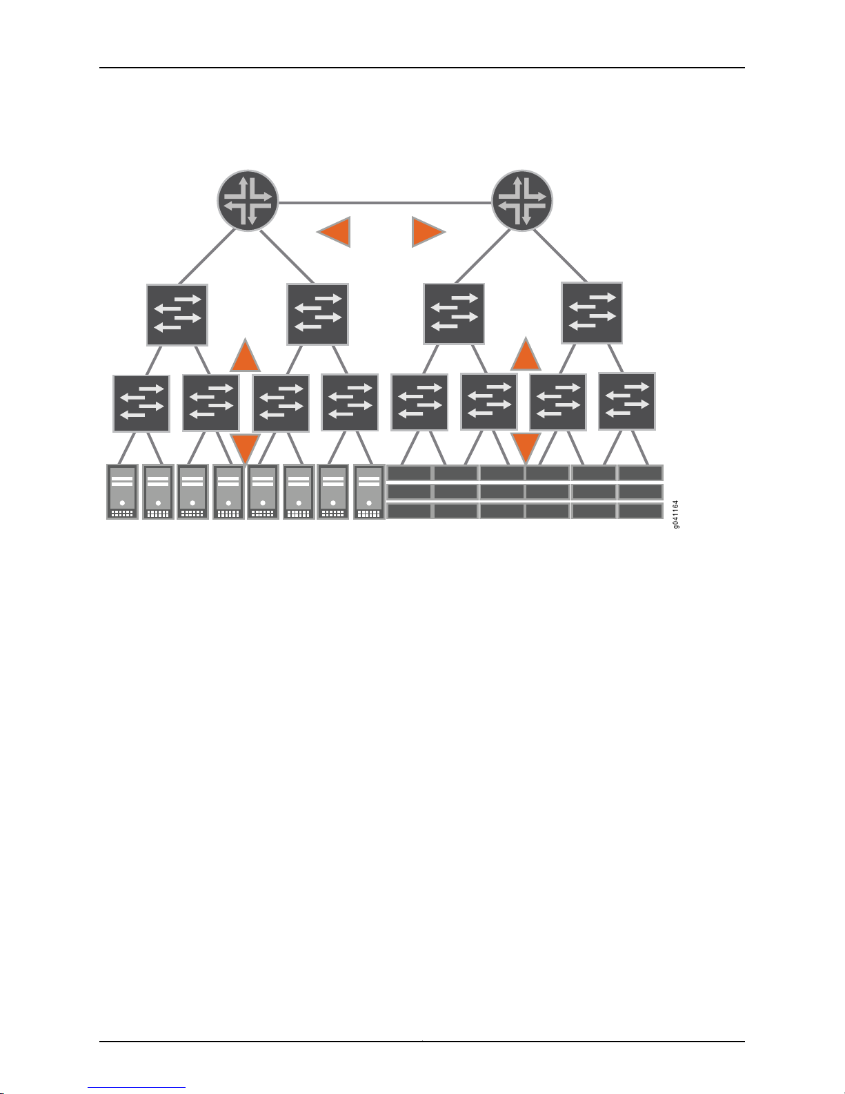
g041164
QFX3000-G QFabric System Deployment Guide
Figure 1: Legacy Data Center Architecture
The access layer connects servers and other devices to a Layer 2 switch and provides an
entry point into the data center. Several access switches are in turn connected to
intermediate Layer 2 switches at the aggregation layer (sometimes referred to as the
distribution layer) to consolidate traffic. A core layer interconnects the aggregation layer
switches. Finally, the core switches are connected to Layer 3 routers in the routing layer
to send the aggregated data center traffic to other data centers or a wide area network
(WAN), receive external traffic destined for the data center, and interconnect different
Layer 2 broadcast domains within the data center.
The problems that exist with the multi-tiered data center architecture include:
•
Limited scalability—The demands for electrical power, cooling, cabling, rack space,
and port density increase exponentially as the traditional data center expands, which
prohibits growth after minimal thresholds are met.
•
Inefficient resource usage—Up to 50 percent of switch ports in a legacy data center
are used to interconnect different tiers rather than support server and storage
connections. In addition, traffic that ideally should move horizontally between servers
within a data center often must also be sent vertically up through the tiers to reach a
router and down through the tiers to reach the required destination server.
•
Increased latency—By requiring the devices at each tier level to perform multiple
iterations of packet and frame processing, the data plane traffic takes significantly
longer to reach its destination than if the sending and receiving devices were directly
connected. This processing overhead results in potentially poor performance for
time-sensitive applications, such as voice, video, or financial transactions.
Copyright © 2015, Juniper Networks, Inc.4
Page 31

QFX Series QFabric System Architecture
Interconnect devices
Virtual Chassis
control plane
Director devices
Node devices
g041145
In contrast to legacy multi-tiered data center architectures, the Juniper Networks QFX
Series QFabric System architecture provides a simplified networking environment that
solves the most challenging issues faced by data center operators. A fabric is a set of
devices that act in concert to behave as a single switch. It is a highly scalable, distributed,
Layer 2 and Layer 3 networking architecture that provides a high-performance,
low-latency, and unified interconnect solution for next-generation data centers as seen
in Figure 2 on page 5.
Figure 2: QFX Series QFabric System Architecture
Chapter 1: Before You Begin
A QFabric system collapses the traditional multi-tiered data center model into a single
tier where all access layer devices (known in the QFabric system model as Node devices)
are essentially directly connected to all other access layer devices across a very large
scale fabric backplane (known in the QFabric system model as the Interconnect device).
Such an architecture enables the consolidation of data center endpoints (such as servers,
storage devices, memory, appliances, and routers) and provides better scaling and
network virtualization capabilities than traditional data centers.
5Copyright © 2015, Juniper Networks, Inc.
Page 32

QFX3000-G QFabric System Deployment Guide
Essentially, a QFabric system can be viewed as a single, nonblocking, low-latency switch
that supports thousands of 10-Gigabit Ethernet ports or 2-Gbps, 4-Gbps, or 8-Gbps Fibre
Channel ports to interconnect servers, storage, and the Internet across a high-speed,
high-performancefabric. The entire QFabric system is managed as a single entity through
a Director group, containing redundant hardware and software components that can be
expanded and scaled as the QFabric system grows in size. In addition, the Director group
automatically senses when devices are added or removed from the QFabric system and
dynamically adjusts the amount of processing resources required to support the system.
Such intelligence helps the QFabric system use the minimum amount of power to run
the system efficiently, but not waste energy on unused components.
As a result of the QFabric system architecture, data center operators are now realizing
the benefits of this next-generation architecture, including:
•
Low latency—Because of its inherent advantages in this area, the QFabric system
provides an excellent foundation for mission-critical applications such as financial
transactions and stock trades, as well as time-sensitive applications such as voice and
video.
•
Enhanced scalability—The QFabric system can be managed as a single entity and
provides support for thousands of data center devices. As Internet traffic continues to
grow exponentially with the increase in high-quality video transmissions and rise in the
number of mobile devices used worldwide, the QFabric system can keep pace with
the demands for bandwidth, applications, and services offered by the data center.
Related
Documentation
•
Virtualization-enabled—The QFabric system was designed to work seamlessly with
virtual servers, virtual appliances, and other virtual devices, allowing for even greater
scalability, expandability, and rapid deployment of new services than ever before.
Migrating to virtual devices also results in significant costs savings, fueled by reduced
space requirements, decreased needs for power and cooling, and increased processing
capabilities.
•
Simplicity—Although the QFabric system can scale to hundreds of devices and
thousands of ports, you can still manage the QFabric system as a single system.
•
Flexibility—You can deploy the QFabric system as an entire system or in stages.
•
Convergence—Because the congestion-free fabric is lossless, all traffic in a QFabric
system can be converged onto a single network. As a result, the QFabric system
supports Ethernet, Fibre Channel over Ethernet, and native Fibre Channel packets and
frames.
Flat, nonblocking, and lossless, the network fabric offered by the QFabric system has the
scale and flexibility to meet the needs of small, medium, and large-sized data centers
for years to come.
Understanding QFabric System Terminology on page 7•
• Understanding the QFabric System Hardware Architecture on page 15
• Understanding the QFabric System Software Architecture on page 31
Copyright © 2015, Juniper Networks, Inc.6
Page 33

Understanding QFabric System Terminology
Supported Platforms QFabric System
To understand the QFabric system environment and its components, you should become
familiar with the terms defined in Table 3 on page 7.
Table 3: QFabric System Terms
DefinitionTerm
Chapter 1: Before You Begin
Clos network fabric
Director device
Director group
Director software
Three-stage switching network in which switch elements in the middle stages
are connected to all switch elements in the ingress and egress stages. In the
case of QFabric system components, the three stages are represented by an
ingress chipset, a midplane chipset, and an egress chipset in an Interconnect
device (such as a QFX3008-I Interconnect device). In Clos networks, which
are well known for their nonblocking properties, a connection can be made
from any idle input port to any idle output port, regardless of the traffic load
in the rest of the system.
Hardwarecomponent that processes fundamental QFabric system applications
and services, such as startup, maintenance, and inter-QFabric system device
communication.A set of Director devices with hard drives can be joined to form
a Director group, which provides redundancy and high availability by way of
additional memory and processing power. (See also Director group.)
Set of Director devices that host and load-balance internal processes for the
QFabric system. The Director group handles tasks such as QFabric system
network topology discovery, Node and Interconnect device configuration,
startup, and DNS, DHCP, and NFS services. Operating a Director group is a
minimum requirement to manage a QFabric system.
The Director group runs the Director software for management applications
and runs dual processes in active/standby mode for maximum redundancy
and high availability. (See also Director software and Director device.)
Software that handles QFabric system administration tasks, such as fabric
management and configuration. The Junos OS-based Director software runs
on the Director group, provides a single, consolidated view of the QFabric
system, and enables the main QFabric system administrator to configure,
manage, monitor, and troubleshoot QFabric system components from a
centralized location. To access the Director software, log in to the default
partition. (See also Director device and Director group.)
fabric control Routing Engine
fabric manager Routing Engine
infrastructure
Virtual Junos OS Routing Engine instance used to control the exchange of
routesand flow of data betweenQFabric systemhardwarecomponents within
a partition. The fabric control Routing Engine runs on the Director group.
Virtual Junos OS Routing Engine instance used to control the initialization and
maintenanceof QFabric system hardware components belonging to the default
partition. The fabric manager Routing Engine runs on the Director group.
QFabric system services processed by the virtual Junos Routing Engines
operatingwithin the Director group. These services, such as fabric management
and fabric control, support QFabric system functionality and high availability.
7Copyright © 2015, Juniper Networks, Inc.
Page 34

QFX3000-G QFabric System Deployment Guide
Table 3: QFabric System Terms (continued)
DefinitionTerm
Interconnect device
Junos Space
network Node group Routing Engine
Node device
partition
QFabric system
QFabric system component that acts as the primary fabric for data plane traffic
traversing the QFabric system between Node devices. An example of an
Interconnectdevice is a QFX3008-I Interconnect device. (See also Node device.)
Carrier-class network management system for provisioning, monitoring, and
diagnosing Juniper Networks routing, switching, security, and data center
platforms.
Set of one to eight Node devices that connects to an external network.network Node group
Virtual Junos OS Routing Engine instance that handles routing processes for
a network Node group. The network Node group Routing Engine runs on the
Director group.
Routing and switching device that connects to endpoints (such as servers or
storage devices) or external network peers, and is connected to the QFabric
system through an Interconnect device. You can deploy Node devices similarly
to the way a top-of-rack switch is implemented. An example of a Node device
is the QFX3500 Node device. (See also Interconnect device and network Node
group.)
Collection of physical or logical QFabric system hardware components (such
as Node devices) that provides fault isolation, separation, and security.
In their initial state, all QFabric system components belong to a default partition.
Highly scalable, distributed, Layer 2 and Layer 3 networking architecture that
provides a high-performance, low-latency, and unified interconnect solution
for next-generation data centers. A QFabric system collapses the traditional
multi-tier data center model, enables the consolidation of data center
endpoints (such as servers, storagedevices, memory,appliances, and routers),
and provides better scaling and network virtualization capabilities than
traditional data centers.
Essentially, a QFabric system can be viewed as a single, nonblocking,
low-latency switch that supports thousands of 10-Gigabit Ethernet ports or
2-Gbps, 4-Gbps or 8-Gbps Fibre Channel ports to interconnectservers,storage,
and the Internet across a high-speed, high-performance fabric. The QFabric
system must have sufficient resources and devices allocated to handle the
Director group, Node device, and Interconnect device functions and capabilities.
Copyright © 2015, Juniper Networks, Inc.8
Page 35

Table 3: QFabric System Terms (continued)
DefinitionTerm
Chapter 1: Before You Begin
QFabric system control plane
QFabric system data plane
Internal network connection that carries control traffic between QFabric system
components. The QFabric system control plane includes management
connections between the following QFabric system hardware and software
components:
•
Node devices, such as the QFX3500 Node device.
•
Interconnect devices, such as the QFX3008-I Interconnect device.
•
Director group processes, such as management applications, provisioning,
and topology discovery.
•
Control plane Ethernet switches to provide interconnections to all QFabric
system devices and processes. For example, you can use EX Series EX4200
switches running in Virtual Chassis mode for this purpose.
To maintain high availability,the QFabric system control plane uses a different
network than the QFabric system data plane, and uses a fabric provisioning
protocol and a fabric management protocol to establish and maintain the
QFabric system.
Redundant, high-performance, and scalable data plane that carries QFabric
system data traffic. The QFabric system data plane includes the following
high-speed data connections:
•
10-Gigabit Ethernet connections between QFabric system endpoints (such
as servers or storage devices) and Node devices.
•
40-Gbps quad small form-factor pluggable plus (QSFP+) connections
between Node devices and Interconnect devices.
•
10-Gigabit Ethernet connections between external networks and a Node
device acting as a network Node group.
To maintain high availability, the QFabric system data plane is separate from
the QFabric system control plane.
QFabric system endpoint
QFabric system fabric
QFX3500 Node device
Device connected to a Node device port, such as a server, a storage device,
memory, an appliance, a switch, or a router.
Distributed, multistage network that consists of a queuing and scheduling
systemthat is implemented in the Node device, and a distributed cross-connect
systemthat is implemented in Interconnectdevices.The QFabric system fabric
is part of the QFabric system data plane.
Node device that connects to either endpoint systems (such as servers and
storage devices) or external networks in a QFabric system. It is packaged in an
industry-standard 1U, 19-inch rack-mounted enclosure.
The QFX3500 Node device provides up to 48 10-Gigabit Ethernet interfaces
to connect to the endpoints. Twelve of these 48 interfaces can be configured
to support 2-Gbps, 4-Gbps or 8-Gbps Fibre Channel, and 36 of the interfaces
can be configured to support Gigabit Ethernet. Also, there are four uplink
connections to connect to Interconnect devices in a QFabric system. These
uplinks use 40-Gbps quad small form-factor pluggable plus (QSFP+)
interfaces. (See also QFX3500 switch.)
9Copyright © 2015, Juniper Networks, Inc.
Page 36

QFX3000-G QFabric System Deployment Guide
Table 3: QFabric System Terms (continued)
DefinitionTerm
QFX3500 switch
QFX3600 Node device
QFX3600 switch
Standalone data center switch with 10-Gigabit Ethernet access ports and
40-Gbps quad, small form-factor pluggable plus (QSFP+) uplink interfaces.
You can (optionally) configure some of the access ports as 2-Gbps, 4-Gbps,
or 8-Gbps Fibre Channel ports or Gigabit Ethernet ports.
The QFX3500 switch can be converted to a QFabric system Node device as
part of a complete QFabric system. The switch is packaged in an
industry-standard 1U, 19-inch rack-mounted enclosure. (See also QFX3500
Node device.)
Node device that connects to either endpoint systems (such as servers and
storage devices) or external networks in a QFabric system. It is packaged in an
industry-standard 1U, 19-inch rack-mounted enclosure.
The QFX3600 Node device provides 16 40-Gbps QSFP+ ports. By default, 4
ports (labeled Q0 through Q3) are configured for 40-Gbps uplink connections
between your Node device and your Interconnectdevice, and 12 ports (labeled
Q4 through Q15) use QSFP+ direct-attach copper (DAC) breakout cables or
QSFP+ transceivers with fiber breakout cables to support 48 10-Gigabit
Ethernet interfaces for connections to either endpoint systems (such as servers
and storage devices) or external networks. Optionally, you can choose to
configure the first eight ports (Q0 through Q7) for uplink connections between
your Node device and your Interconnect device, and ports Q2 through Q15 for
10-Gigabit Ethernet connections to either endpoint systems or external
networks. (See also QFX3600 switch.)
Standalone data center switch with 16 40-Gbps quad, small form-factor
pluggable plus (QSFP+) interfaces. By default, all the 16 ports operate as
40-Gigabit Ethernet ports. Optionally,you can choose to configure the 40-Gbps
ports to operate as four 10-Gigabit Ethernet ports. You can use QSFP+ to four
SFP+ breakout cables to connect the 10-Gigabit Ethernet ports to other servers,
storage, and switches.
redundant server Node group
rolling upgrade
Routing Engine
The QFX3600 switch can be converted to a QFabric system Node device as
part of a complete QFabric system. The switch is packaged in an
industry-standard 1U, 19-inch rack-mounted enclosure. (See also QFX3600
Node device.)
Set of two Node devices that connect to servers or storage devices. Link
aggregation group (LAG) interfaces can span the Node devices within a
redundant server Node group.
Method used in the QFabric system to upgrade the software for components
in a systematic, low-impact way. A rolling upgrade begins with the Director
group, proceeds to the fabric (Interconnect devices), and finishes with the
Node groups.
Juniper Networks-proprietaryprocessingentity that implements QFabric system
control plane functions, routing protocols, system management, and user
access. Routing Engines can be either physical or virtual entities.
The Routing Engine functions in a QFabric system are sometimes handled by
Node devices (when connected to endpoints), but mostly implemented by
the Director group (to provide support for QFabric system establishment,
maintenance, and other tasks).
Copyright © 2015, Juniper Networks, Inc.10
Page 37

Table 3: QFabric System Terms (continued)
DefinitionTerm
Chapter 1: Before You Begin
routing instance
virtual LAN (VLAN)
virtual private network (VPN)
Related
Documentation
Privatecollectionof routing tables, interfaces,and routing protocol parameters
unique to a specific customer. The set of interfaces is contained in the routing
tables, and the routing protocol parameters control the information in the
routing tables.
(See also virtual private network.)
Set of one or more Node devices that connect to servers or storage devices.server Node group
Unique Layer 2 broadcast domain for a set of ports selected from the
components available in a partition. VLANs allow manual segmentation of
larger Layer 2 networks and help to restrict access to network resources. To
interconnect VLANs, Layer 3 routing is required.
Layer 3 routing domain within a partition. VPNs maintain privacy with a
tunneling protocol, encryption, and security procedures. In a QFabric system,
a Layer 3 VPN is configured as a routing instance.
QFabric System Overview on page 3•
• Understanding the QFabric System Hardware Architecture on page 15
• Understanding the QFabric System Software Architecture on page 31
• Understanding Fibre Channel Terminology
Understanding Interfaces on the QFabric System
Supported Platforms QFabric System
This topic describes:
•
Four-Level Interface Naming Convention on page 11
•
QSFP+ Interfaces on page 12
•
Link Aggregation on page 14
Four-Level Interface Naming Convention
When you configure an interface on the QFabric system, the interface name needs to
follow a four-level naming convention that enables you to identify an interface as part
of either a Node device or a Node group. Include the name of the network or server Node
group at the beginning of the interface name.
The four-level interface naming convention is:
device-name:type-fpc/pic/port
where device-name is the name of the Node device or Node group. The remainder of the
naming convention elements are the same as those in the QFX3500 switch interface
naming convention.
11Copyright © 2015, Juniper Networks, Inc.
Page 38

QFX3000-G QFabric System Deployment Guide
An example of a four-level interface name is:
node2:xe-0/0/2
QSFP+ Interfaces
The QFX3500 Node device provides four 40-Gbps QSFP+ (quad small form-factor
pluggable plus) interfaces (labeled Q0 through Q3) for uplink connections between your
Node device and your Interconnect devices.
The QFX3600 Node device provides16 40-Gbps QSFP+ interfaces.By default, 4 interfaces
(labeled Q0 through Q3) are configured for 40-Gbps uplink connections between your
Node device and your Interconnect devices, and 12 interfaces (labeled Q4 through Q15)
use QSFP+ direct-attach copper (DAC)breakout cables or QSFP+ transceiverswith fiber
breakout cables to support 48 10-Gigabit Ethernet interfaces for connections to either
endpoint systems (such as servers and storage devices) or external networks. Optionally,
you can choose to configure the first eight interfaces (Q0 through Q7) for uplink
connections between your Node device and your Interconnect devices, and interfaces
Q2 through Q15 for 10-Gigabit Ethernet connections to either endpoint systems or external
networks (see “Configuring the Port Type on QFX3600 Node Devices” on page 392).
Table 4 on page 12 shows the port mappings for QFX3600 Node devices.
Table 4: QFX3600 Node Device Port Mappings
40-Gigabit Data Plane Uplink
InterfacesPort Number
fte-0/1/2Q2
fte-0/1/3Q3
fte-0/1/4Q4
10-Gigabit Ethernet Interfaces
Not supported on this portfte-0/1/0Q0
Not supported on this portfte-0/1/1Q1
xe-0/0/8
xe-0/0/9
xe-0/0/10
xe-0/0/11
xe-0/0/12
xe-0/0/13
xe-0/0/14
xe-0/0/15
xe-0/0/16
xe-0/0/17
xe-0/0/18
xe-0/0/19
Copyright © 2015, Juniper Networks, Inc.12
Page 39

Table 4: QFX3600 Node Device Port Mappings (continued)
40-Gigabit Data Plane Uplink
InterfacesPort Number
Chapter 1: Before You Begin
10-Gigabit Ethernet Interfaces
fte-0/1/5Q5
fte-0/1/6Q6
fte-0/1/7Q7
Not supported on this portQ8
xe-0/0/20
xe-0/0/21
xe-0/0/22
xe-0/0/23
xe-0/0/24
xe-0/0/25
xe-0/0/26
xe-0/0/27
xe-0/0/28
xe-0/0/29
xe-0/0/30
xe-0/0/31
xe-0/0/32
xe-0/0/33
xe-0/0/34
xe-0/0/35
Not supported on this portQ9
Not supported on this portQ10
Not supported on this portQ11
xe-0/0/36
xe-0/0/37
xe-0/0/38
xe-0/0/39
xe-0/0/40
xe-0/0/41
xe-0/0/42
xe-0/0/43
xe-0/0/44
xe-0/0/45
xe-0/0/46
xe-0/0/47
13Copyright © 2015, Juniper Networks, Inc.
Page 40

QFX3000-G QFabric System Deployment Guide
Table 4: QFX3600 Node Device Port Mappings (continued)
40-Gigabit Data Plane Uplink
InterfacesPort Number
10-Gigabit Ethernet Interfaces
Not supported on this portQ12
Not supported on this portQ13
Not supported on this portQ14
Not supported on this portQ15
xe-0/0/48
xe-0/0/49
xe-0/0/50
xe-0/0/51
xe-0/0/52
xe-0/0/53
xe-0/0/54
xe-0/0/55
xe-0/0/56
xe-0/0/57
xe-0/0/58
xe-0/0/59
xe-0/0/60
xe-0/0/61
xe-0/0/62
Link Aggregation
Related
Documentation
xe-0/0/63
Link aggregation enables you to create link aggregation groups across Node devices
within a network Node group or redundant server Node group. You can include up to 32
Ethernet interfaces in a LAG. You can have up to 48 LAGs within a redundant server Node
group, and 128 LAGs in a network Node group. To configure a LAG, include the
aggregated-devices statement at the [edit chassis node-group node-group-name] hierarchy
level and the device-count statement at the [edit chassis node-group node-group-name
aggregated-devices ethernet] hierarchy level.Additionally, include any aggregated Ethernet
options (minimum-links and link-speed) at the [edit interfaces interface-name
aggregated-ether-options] hierarchy level and the 802.3ad statement at the [edit
interfacesinterface-nameether-options] hierarchy level. To configure the Link Aggregation
Control Protocol (LACP), include the lacp statement at the [edit interfaces
aggregated-ether-options] hierarchy level.
• Configuring the Port Type on QFX3600 Node Devices on page 392
Copyright © 2015, Juniper Networks, Inc.14
Page 41

CHAPTER 2
Hardware Architecture Overview
•
Understanding the QFabric System Hardware Architecture on page 15
•
Understanding the Director Group on page 18
•
Understanding Routing Engines in the QFabric System on page 19
•
Understanding Interconnect Devices on page 21
•
Understanding Node Devices on page 24
•
Understanding Node Groups on page 27
•
Understanding Port Oversubscription on Node Devices on page 29
Understanding the QFabric System Hardware Architecture
Supported Platforms QFabric System
•
QFabric System Hardware Architecture Overview on page 15
•
QFX3000-G QFabric System Features on page 18
•
QFX3000-M QFabric System Features on page 18
QFabric System Hardware Architecture Overview
The QFabric system is a single-layer networking tier that connects servers and storage
devices to one another across a high-speed, unified core fabric. You can view the QFabric
system as a single, extremely large, nonblocking, high-performance Layer 2 and Layer 3
switching system. The reason you can consider the QFabric system as a single system
is that the Director software running on the Directorgroup allows the main QFabric system
administrator to access and configure every device and port in the QFabric system from
a single location. Although you configure the system as a single entity, the fabric contains
four major hardware components. The hardware components can be chassis-based,
group-based, or a hybrid of the two. As a result, it is important to understand the four
types of generic QFabric system components and their functions, regardless of which
hardware environment you decide to implement. A representation of these components
is shown in Figure 3 on page 16.
15Copyright © 2015, Juniper Networks, Inc.
Page 42

Virtual Chassis
(control plane)
Interconnect devices
Node devices
Director devices
g041135
QFX3000-G QFabric System Deployment Guide
Figure 3: QFabric System Hardware Architecture
The four major QFabric system components include the following:
•
Director group—The Director group is a management platform that establishes,
monitors, and maintains all components in the QFabric system. It is a set of Director
devicesthat run the Junos operating system (Junos OS) on top of a CentOS foundation.
The Director group handles tasks such as QFabric system network topology discovery,
Node and Interconnect device configuration and startup, and Domain Name System
(DNS), Dynamic Host ConfigurationProtocol (DHCP), and Network File System (NFS)
services. The Directorgroup also runs the software for management applications, hosts
and load-balances internal processes for the QFabric system, and starts additional
QFabric system processes as requested.
•
Node devices—A Node device is a hardware system located on the ingress of the
QFabric system that connects to endpoints (such as servers or storage devices) or
external networks, and is connected to the heart of the QFabric system through an
Interconnectdevice.A Node device can be used in a manner similar to how a top-of-rack
switch is implemented. By default, Node devices connect to servers or storage devices.
However, when you group Node devices together to connect to a network that is
external to the QFabric system, the formation is known as a network Node group.
•
Interconnectdevices—An Interconnect device acts as the primary fabric for data plane
traffic traversing the QFabric system between Node devices. To reduce latency to a
minimum, the Interconnect device implements multistage Clos switching to provide
nonblocking interconnections between any of the Node devices in the system.
•
Control plane network—The control plane network is an out-of-band Gigabit Ethernet
management network that connects all QFabric system components. For example,
you can use a group of EX4200 Ethernet switches configured as a Virtual Chassis to
enable the control plane network. The control plane network connects the Director
Copyright © 2015, Juniper Networks, Inc.16
Page 43

group to the management ports of the Node and Interconnect devices. By keeping the
control plane network separate from the data plane, the QFabric system can scale to
support thousands of servers and storage devices.
The four major QFabric system components can be assembled from a variety of hardware
options. Currently supported hardware configurations are shown in Table 5 on page 17.
Table 5: Supported QFabric System Hardware Configurations
QFabric
System
Configuration
Chapter 2: Hardware Architecture Overview
Control Plane DeviceInterconnectDeviceNode DeviceDirector Group
QFX3000-G
QFabric system
QFX3000-M
QFabric system
QFX3100 Director
group
QFX3100 Director
group
NOTE: For a
copper-based
QFX3000-M QFabric
system control plane
network, use QFX3100
Director devices with
RJ-45 network
modules installed. For
a fiber-based control
plane network, use
QFX3100 Director
devices with SFP
network modules
installed.
QFX3500 and QFX3600 Node
device
NOTE: There can be a
maximum of 128 Node devices
in the QFX3000-G QFabric
system.
QFX3500 and QFX3600 Node
device
NOTE:
•
There can be a maximum of
16 Node devices in the
QFX3000-M QFabric
system.
•
For a copper-based
QFX3000-M QFabric
system control plane
network, use QFX3500
Node devices with a
1000BASE-T management
board installed. For a
fiber-based control plane
network, use QFX3500
Node devices with an SFP
management board
installed.
QFX3008-I
Interconnect device
NOTE: There can be
a maximum of four
Interconnect devices
in the QFX3000-G
QFabric system.
QFX3600-I
Interconnect device
NOTE: There can be
a maximum of four
Interconnect devices
in the QFX3000-M
QFabric system.
Two Virtual Chassis
composed of four
EX4200 switches each
Two EX4200 Ethernet
switches
NOTE: For a
copper-based
QFX3000-M QFabric
system control plane
network, use
EX4200-24T switches
with an SFP+ uplink
module installed. For a
fiber-based control plane
network, use
EX4200-24F switches
with an SFP+ uplink
module installed.
To complete the system, external Routing Engines (such as the fabric manager Routing
Engines, network Node group Routing Engines, and fabric control Routing Engines) run
on the Directorgroup and implement QFabric system control plane functions. The control
plane network provides the control plane connections between the Node devices, the
Interconnect devices, and the Routing Engines running on the Director group.
17Copyright © 2015, Juniper Networks, Inc.
Page 44

QFX3000-G QFabric System Deployment Guide
QFX3000-G QFabric System Features
A QFX3000-G QFabric system provides the following key features:
•
Support for up to 128 Node devices and 4 Interconnect devices, which provides a
maximum of 6144 10-Gigabit Ethernet ports.
•
Low port-to-port latencies that scale as the system size grows from 48 to 6144
10-Gigabit Ethernet ports.
•
Support for up to 384,000 total ingress queues at each Node device to the QFabric
system Interconnect backplane.
•
Support for Converged Enhanced Ethernet (CEE) traffic.
QFX3000-M QFabric System Features
A QFX3000-M QFabric system provides the following key features:
•
Support for up to 16 Node devices and 4 Interconnect devices, which provides a
maximum of 768 10-Gigabit Ethernet ports.
•
Low port-to-port latencies that scale as the system size grows from 48 to 768
10-Gigabit Ethernet ports.
Related
Documentation
Understanding QFabric System Terminology on page 7•
• Understanding the QFabric System Software Architecture on page 31
• Understanding the Director Group on page 18
• Understanding Routing Engines in the QFabric System on page 19
• Understanding Interconnect Devices on page 21
• Understanding Node Devices on page 24
• Understanding Node Groups on page 27
• Understanding Partitions on page 33
Understanding the Director Group
Supported Platforms QFabric System
Because the Director group provides management services for the QFabric system, it is
important to understand the components of the cluster and how the Director group
supports the needs of the greater fabric.
•
Director Group Components on page 18
•
Director Group Services on page 19
Director Group Components
When you build a Director group, consider the following elements and concepts.
Copyright © 2015, Juniper Networks, Inc.18
Page 45

Chapter 2: Hardware Architecture Overview
•
Directordevice—A single management device for the QFabric system. Director devices
with a hard drive provide full processing services and are used to build the Director
group.
•
Directorgroup—A set of Director devices. The Director group is essential to the QFabric
system, which cannot operate properly without it. The Director group shares and
load-balances processing tasks for the QFabric system, performs topology discovery,
assigns identifiers to QFabric system components, and manages interfabric
communication. The primary devices in a Director group are Director devices that
contain hard drives. The Director devices run dual processes in active or standby mode
for maximum redundancy.
When you add additional Director devices to the group, the Director group coordinates
their activities and distributes processing loads across all available Director devices.
The additional Director devices provide the Director group with additional memory and
processing power.Supplementing the Director group with extra Directordevices allows
the group to scale efficiently and serve the needs of the entire QFabric system as it
grows.
Director Group Services
The Director group is a management platform that establishes, monitors, and maintains
all components in the QFabric system. It is a set of Director devices that run the Junos
operating system (Junos OS) on top of a CentOS foundation. The Director group handles
tasks such as QFabric system network topology discovery,Node and Interconnect device
configurationand startup, and Domain Name System(DNS), Dynamic Host Configuration
Protocol (DHCP), and Network File System (NFS) services. The Director group also runs
the software for management applications, hosts and load-balances internal processes
for the QFabric system, maintains configuration and topology databases, and starts
additional QFabric system processes as requested.
Another critical role provided by the Director group is the hosting of the virtual Junos
Routing Engines. These Routing Engines provide services for the QFabric system to keep
it operating smoothly.
Related
Documentation
Performingthe QFabric System Initial Setup on a QFX3100 Director Group on page 362•
• Understanding Routing Engines in the QFabric System on page 19
• Understanding the QFabric System Hardware Architecture on page 15
Understanding Routing Engines in the QFabric System
Supported Platforms QFabric System
19Copyright © 2015, Juniper Networks, Inc.
Page 46

Fabric control
Fabric manager
Network Node group
Fabric visualizer
Diagnostics
g041148
QFX3000-G QFabric System Deployment Guide
Routing Engines perform many important processing tasks in the QFabric system. Knowing
where the Routing Engines are located and what services they provide enables you to
troubleshoot the QFabric system and ensure that it is running the way it should.
This topic covers:
•
Hardware-Based Routing Engines on page 20
•
Software-Based External Routing Engines on page 20
Hardware-Based Routing Engines
A traditional Juniper Networks Routing Engine is a hardware field-replaceable unit that
runs routing protocols, builds the routing and switching tables, sends routing information
to the Packet Forwarding Engine, and handles several software processes for the device
(such as interface control, chassis component monitoring, system management, and
user access). Node devices that are part of server Node groups in the QFabric system
that connect to servers or storage devices implement Routing Engine functions locally
using this traditional hardware method.
Software-Based External Routing Engines
The QFabric systemalso uses external Routing Engines that run in software on the Director
group. In contrast with traditional Routing Engines, the functions and processes provided
by software-based Routing Engines are segmented, specialized, and distributed across
multipleRouting Engine instances running on the Directorgroup. Such separation provides
redundancy for these functions and enables the QFabric system to scale.
Figure 4 on page 20 shows the external Routing Engine types.
Figure 4: External Routing Engine Types
These special-purpose external Routing Engine instances running on the Director group
provide the following major services for the QFabric system:
•
Fabric manager Routing Engine—Providesservices to all devices in the QFabric system,
such as systeminitialization, topology discovery, internal IP address and ID assignment,
and interdevice communication. The fabric manager Routing Engine authenticates
Interconnect and Node devices, and maintains a database for system components. A
single fabric manager Routing Engine instance is generated to manage the entire
QFabric system.
•
Fabric control Routing Engine—Runs the fabric control protocol to share route
information between available devices in a partition. A pair of redundant route
Copyright © 2015, Juniper Networks, Inc.20
Page 47

Chapter 2: Hardware Architecture Overview
distribution Routing Engine instances is generated for every partition in the QFabric
system, and both instances are active.
•
Diagnostic Routing Engine—Gathers operational information that allows QFabric
system administrators to monitor the health of the QFabric system. A single Routing
Engine instance is generated for the entire QFabric system.
•
NetworkNode group Routing Engine—Provides Routing Engine functionality for groups
of Node devices bundled together as a single Layer 3 routing device, which is used to
connect to externalnetworks.A pair of redundant Routing Engine instances is generated
for every network Node group in the QFabric system.
Related
Documentation
Understanding the Director Group on page 18•
• Understanding the QFabric System Control Plane on page 35
• Understanding the QFabric System Hardware Architecture on page 15
Understanding Interconnect Devices
Supported Platforms QFabric System
Interconnect devices in a QFabric system provide a way for the Node devices to connect
with one another over a high-speed backplane. By understanding the role of Interconnect
devices, you can harness the benefits of low latency, superb scalability, and minimum
packet processing offered by a single-tier data center architecture.
This topic covers:
•
Interconnect Device Introduction on page 21
•
QFX3008-I Interconnect Devices on page 22
•
QFX3600-I Interconnect Devices on page 23
Interconnect Device Introduction
Interconnectdevices act as the primary fabric for data plane traffic traversing the QFabric
system between Node devices. The main task for the Interconnect devices is to transfer
traffic between the Node devices as quickly as possible across a high-speed, available
path backplane. To reduce latency to a minimum, larger Interconnect devices (such as
the QFX3008-I Interconnect device) implement multistage Clos switching to provide
nonblocking connections between any of the Node devices in the system.
Figure 5 on page 22 shows an example of how Clos switching works in the QFX3008-I
Interconnect device.
21Copyright © 2015, Juniper Networks, Inc.
Page 48

IC0
F1
Incoming traffic
Outgoing traffic
Front Card Rear Card
F3
F2
g041161
QFX3000-G QFabric System Deployment Guide
Figure 5: Clos Switching for QFX3008-I Interconnect Devices
Traffic enters a QSFP+ port from a Node device, and an ingress chipset provides stage
F1 processing. For the F2 stage, the frame is sent to a rear card and processed by a
midplane chipset. Lastly, an egress chipset on the front card QSFP+ port handles
processing tasks for the F3 stage. At each of the three Clos stages, a switching table
chooses the best path and determines where to send the frame to reach the next stage.
The F1 and F3 stages can be handled by the same front card or different front cards,
depending on the best path selected by the fabric. After the frame traverses the
Interconnect device backplane, the Interconnect device sends the frame to the egress
Node device.
QFX3008-I Interconnect Devices
The QFX3008-I Interconnect device contains eight slots in the front of the chassis. In
each slot, you can install a front card containing 16 40-Gbps quad small form-factor
pluggable plus (QSFP+) ports. A fully configured system offers a total capacity of 128
QSFP+ connections. These front card ports attach to the high-speed backplane to reach
the eight slots in the rear of the chassis, which provide the heavy-duty interconnections
for the entire QFX3000-G QFabric system. In addition, four interfaces (two per Control
Board) provide Gigabit Ethernet access to the control plane management network.
Figure 6 on page 23 shows an example of the data plane and control plane connections
for QFX3008-I Interconnect devices.
Copyright © 2015, Juniper Networks, Inc.22
Page 49

VC0
VC1
c0
ge-3/0/39
ge-1/0/39
ge-2/0/39
ge-3/0/39
ge-0/0/39
IC0
IC1
ge-2/0/39
ge-0/0/39
ge-1/0/39
cb0
cb1
cb0
cb1
Port 0 Port 1
Port 0
Port 1
Port 0 Port 1
Port 0
Port 1
g041147
Node0
Node0:fte-0/1/1
Node0:xe-0/0/0
Node0:fte-0/1/3
Node0:xe-0/0/46
IC0:fte-7/0/0
IC1:fte-0/0/0
Server
Storage
Data
Plane
Control
Plane
Chapter 2: Hardware Architecture Overview
Figure 6: QFX3008-I Data Plane and Control Plane Connections
QFX3600-I Interconnect Devices
The QFX3600-I Interconnect device has 16 40-Gbps quad small form-factor pluggable
plus (QSFP+) ports that provide interconnections for the entire QFX3000-M QFabric
system.In addition, two management ports provide Gigabit Ethernet access to the control
plane management network. Figure 7 on page 24 shows an example of the data plane
and control plane connections for a QFX3600-I Interconnect device.
23Copyright © 2015, Juniper Networks, Inc.
Page 50

g041235
Node0
Node0:fte-0/1/1
Node0:xe-0/0/0
Node0:fte-0/1/3
Node0:xe-0/0/46
IC0:fte-0/1/0
IC1:fte-0/1/0
Server
Storage
Data
Plane
Control
Plane
EX0
EX1
ge-0/0/17
IC0
IC1
Port C0 Port C1 Port C0 Port C1
ge-0/0/16ge-0/0/17ge-0/0/16
QFX3000-G QFabric System Deployment Guide
Figure 7: QFX3600-I Data Plane and Control Plane Connections
Related
Documentation
Understanding Node Devices on page 24•
• Understanding the QFabric System Data Plane on page 38
• Understanding the QFabric System Control Plane on page 35
• Understanding the QFabric System Hardware Architecture on page 15
Understanding Node Devices
Supported Platforms QFabric System
Node devices in a QFabric systemprovide a way for servers, storage devices, and external
networks to connect to the QFabric system. By understanding the role of Node devices,
you can design your QFabric system topology to take advantage of the unique benefits
offered by a single-tier data center architecture.
Node Device Introduction
This topic covers:
•
Node Device Introduction on page 24
•
QFX3500 Node Devices on page 25
•
QFX3600 Node Devices on page 26
A Node device in the QFabric system connects either endpoint systems (such as
application servers and storage devices) or external networks to Interconnect devices.
It can be used similarly to the way a top-of-rack switch is implemented in a data center.
Node devices provide an access point to the QFabric system, allowing data to flow into
Copyright © 2015, Juniper Networks, Inc.24
Page 51

and out of the QFabric system. Because all Node devices in the QFabric system connect
through a backplane of Interconnect devices, in essence all Node devices are connected
to one another. This directly connected design model eliminates multiple tiers of
aggregation and core devices and provides minimum latency, maximum scalability, and
rapid transport of server-to-servertraffic and QFabric system-to-externalnetwork traffic.
Sets of Node devices can be bundled together into Node groups, in which each group
operates as a single virtual entity. Node groups that connect to servers and storage
devices are known as server Node groups, and Node groups that connect to external
networks are known as network Node groups.
QFX3500 Node Devices
The QFX3500 Node device works as part of a QFabric system. A QFX3500 chassis
provides up to 48 10-Gigabit Ethernet interfaces to connect to endpoints or external
networks. You can configure 12 of these 48 interfaces to support 2-Gbps, 4-Gbps, or
8-Gbps Fibre Channel. You can also configure the remaining 36 interfaces with Gigabit
Ethernet.
Chapter 2: Hardware Architecture Overview
NOTE: You can configure interface ports 0 through 47 as 10-Gigabit Ethernet
ports, 0 through 5 and 42 through 47 as Fibre Channel over Ethernet ports,
and 6 through 41 as Gigabit Ethernet ports. However, you cannot configure
any Fibre Channel over Ethernet ports as Gigabit Ethernet ports or vice versa.
In addition to these server and network interfaces, there are four uplink interfaces to
connect the QFX3500 Node device to Interconnect devices in a QFabric system. These
uplinks use 40-Gbps quad small form-factor pluggable plus (QSFP+) interfaces.
The control plane requires two management ports on the QFX3500 chassis to connect
the Node device to the control plane network. Figure 8 on page 26 shows an example of
the data plane and control plane connections for a QFX3500 Node device.
25Copyright © 2015, Juniper Networks, Inc.
Page 52

VC0
VC1
ge-0/0/0
ge-0/0/0
C1
C0
Data
Plane
Control
Plane
Front view
Rear view
IC0
IC1
IC0:fte-7/0/6
IC1:fte-0/0/6
Node0:fte-0/1/0
Node0:xe-0/0/0
Node0:fte-0/1/2
Node0:xe-0/0/46
Node0
Server
Storage
g041146
QFX3000-G QFabric System Deployment Guide
Figure 8: QFX3500 Data Plane and Control Plane Connections
QFX3600 Node Devices
The QFX3600 Node device works as part of a QFabric system. A QFX3600 chassis
provides 16 40-Gbps QSFP+ interfaces. By default, 4 interfaces (labeled Q0 through Q3)
are configured for 40-Gbps uplink connections between your QFX3600 Node device and
your Interconnect device, and 12 interfaces (labeled Q4 through Q15) use QSFP+
direct-attach copper (DAC) breakout cables or QSFP+ transceivers with fiber breakout
cables to support 48 10-Gigabit Ethernet interfaces for connections to either endpoint
systems or external networks. Optionally, you can choose to configure the first eight
interfaces (Q0 through Q7) for uplink connections between your Node device and your
Interconnect devices, and interfaces Q2 through Q15 for 10-Gigabit Ethernet connections
to either endpoint systems or external networks.
The control plane requires two management ports on the QFX3600 chassis to connect
the Node device to the control plane network. Figure 9 on page 27 shows an example of
the data plane and control plane connections for a QFX3600 Node device.
Copyright © 2015, Juniper Networks, Inc.26
Page 53

VC0
VC1
ge-0/0/0
ge-0/0/0
C1C0
Data
Plane
Control
Plane
IC0
IC1
IC0:fte-7/0/6
IC1:fte-0/0/6
Node0:fte-0/1/0
Node0:fte-0/1/1
g041255
Node0
Node0:xe-0/0/20
Node0:xe-0/0/28
Server
Storage
Chapter 2: Hardware Architecture Overview
Figure 9: QFX3600 Data Plane and Control Plane Connections
Understanding Node Groups
Related
Documentation
Converting the Device Mode for a QFabric System Component on page 277•
• Configuring Aliases for the QFabric System on page 382
• Configuring Node Groups for the QFabric System on page 395
• Configuring the Port Type on QFX3600 Node Devices on page 392
• Understanding Node Groups on page 27
• Understanding Interconnect Devices on page 21
• Understanding the QFabric System Data Plane on page 38
• Understanding the QFabric System Control Plane on page 35
• Understanding the QFabric System Hardware Architecture on page 15
Supported Platforms QFabric System
27Copyright © 2015, Juniper Networks, Inc.
Page 54

QFX3000-G QFabric System Deployment Guide
Node groups help you combine multiple Node devices into a single virtual entity within
the QFabric system to enable redundancy and scalability at the edge of the data center.
This topic covers:
•
Network Node Groups on page 28
•
Server Node Groups on page 28
Network Node Groups
A set of one or more Node devices that connect to an externalnetwork is called a network
Node group. The network Node group also relies on two external Routing Engines running
on the Director group. These redundant network Node group Routing Engines run the
routing protocols required to support the connections from the network Node group to
external networks.
When configured, the Node devices within a network Node group and the network Node
group Routing Engines work together in tandem as a single entity. By default, network
Node group Routing Engines are part of the NW-NG-0 network Node group but no Node
devices are included in the group. As a result, you must configure Node devices to be part
of a network Node group.
Server Node Groups
In a QFabric system deployment that requires connectivity to external networks, you can
modify the automatically generated network Node group by including its preset name
NW-NG-0 in the Node group configuration. Within a network Node group, you can include
a minimum of one Node device up to a maximum of eight Node devices. By adding more
Node devices to the group, you provide enhanced scalability and redundancy for your
network Node group.
NOTE: The QFabric system creates a single NW-NG-0 network Node group
for the default partition. You cannot configure a second network Node group
inside the default partition. The remaining Node devices within the default
partition are reserved to connect to servers, storage, or other endpoints
internal to the QFabric system. These Node devices either can be retained in
the automatically generated server Node groups or can be configured as part
of a redundant server Node group.
A server Node group is a set of one or more Node devices that connect to servers or storage
devices. Unlike Node devices that are part of a network Node group and rely on an external
Routing Engine, a Node device within a server Node group connects directly to endpoints
and implements the Routing Engine functions locally, using the local CPU built into the
Node device itself.
By default, each Node device is placed in its own self-named autogenerated server Node
group to connect to servers and storage. You can override the default assignment by
manually configuring a redundant server Node group that contains a maximum of two
Node devices. You can use a redundant server Node group to provide multihoming services
Copyright © 2015, Juniper Networks, Inc.28
Page 55

Chapter 2: Hardware Architecture Overview
to servers and storage, as well as configure aggregated LAG connections that span the
two Node devices.
NOTE: The Node devices in a redundant server Node group must be of the
same type, either a QFX3500 Node device or a QFX3600 Node device. You
cannot add a QFX3500 and a QFX3600 Node device to the same redundant
server Node group.
Related
Documentation
Configuring Node Groups for the QFabric System on page 395•
• Understanding Node Devices on page 24
• Understanding Routing Engines in the QFabric System on page 19
• Understanding the QFabric System Hardware Architecture on page 15
Understanding Port Oversubscription on Node Devices
Supported Platforms QFabric System
Each Node device in a QFabric system can have a different port oversubscription
configuration. For example, you can have a Node device with 3:1 port oversubscription,
another with 6:1 oversubscription, and yet another with 1:1 oversubscription.
The port oversubscription ratio on a Node device is based on the number of uplink
connections from the Node device to Interconnectdevices. For example, you can configure
1:1 port oversubscription on your QFX3600 Node device by connecting the eight uplink
ports (labeled Q0 through Q7) on the Node device to Interconnect devices.
Table 6 on page 29 shows the oversubscription ratio for ports on Node devices based on
the number of Interconnect devices and the number of connections from each Node
device to each Interconnect device.
Table 6: Oversubscription Ratio on Node Devices
Number of Connections from Each
Number of Interconnect
Devices
Node Device to Each Interconnect
Device
Oversubscription Ratio on Node Device
6:112
3:122
1:1 (Supported on QFX3600 Node devices only)42
3:114
1:1 (Supported on QFX3600 Node devices only)24
29Copyright © 2015, Juniper Networks, Inc.
Page 56

QFX3000-G QFabric System Deployment Guide
Related
Documentation
• Connecting a QFX3500 Node Device to a QFX3008-I Interconnect Device on page 271
• Connecting a QFX3600 Node Device to a QFX3008-I InterconnectDevice on page 269
• Connecting a QFX3500 Node Device to a QFX3600-I Interconnect Device
• Connecting a QFX3600 Node Device to a QFX3600-I Interconnect Device
Copyright © 2015, Juniper Networks, Inc.30
Page 57

CHAPTER 3
Software Architecture Overview
•
Understanding the QFabric System Software Architecture on page 31
•
Understanding the Director Software on page 32
•
Understanding Partitions on page 33
•
Understanding the QFabric System Control Plane on page 35
•
Understanding the QFabric System Data Plane on page 38
Understanding the QFabric System Software Architecture
Supported Platforms QFabric System
The software architecture for the QFabric system environment has been designed to
provide a high-speed, low-latency, nonblocking fabric for data center traffic. This topic
explores how the software architecture for a QFabric system supports these goals.
Key components of the QFabric system software architecture include:
•
A single administrative view of all QFabric system components provides unified
management, configuration, monitoring, and troubleshooting of the QFabric system.
This view is provided by the QFX Series Director software running on the Director group.
A primary administrator can access the unified view through the default partition.
•
A fabric control protocol enables rapid transport of data traffic between QFabric system
components. This unique feature of the software architecture distributes route
information for each device within the QFabric system, and removes the need to run
spanning-tree protocols inside the QFabric system network.
•
A fabric management protocol provides rapid transport of control traffic between
QFabric system components. This protocol helps identify and initialize QFabric system
resources, supports device redundancy, and supports management communication
throughout the QFabric system.
•
A control plane network that is separate from the data plane network provides high
availability for the QFabric system.
The software also provides access to relevant features in the Junos operating system
(Junos OS) that support QFabric system functionality. Support is available for most
switching features available on EX Series Ethernet switches and many routing features
available on M Series, MX Series, and T Series routing platforms.
31Copyright © 2015, Juniper Networks, Inc.
Page 58

QFX3000-G QFabric System Deployment Guide
Related
Documentation
Understanding QFabric System Terminology on page 7•
• Understanding the QFabric System Hardware Architecture on page 15
• Understanding the Director Software on page 32
• Understanding Partitions on page 33
• Understanding the QFabric System Control Plane on page 35
• Understanding the QFabric System Data Plane on page 38
Understanding the Director Software
Supported Platforms QFabric System
The Director software provides a single view into the QFabric system so that it can be
managed as a single entity. This topic explains how the Director software interacts with
the components of the QFabric system to maintain operations from a central location.
Because the QFabric system consists of multiple Director, Node, and Interconnect devices,
the architects of the QFabric system determined that it would be useful to manage the
entire system as a single logical entity. As a result, the Director software handles
administration tasks for the entire QFabric system, such as fabric management and
configuration. The Director software runs on the Director group, provides a single
consolidated view of the QFabric system, and enables the main QFabric system
administrator to configure, manage, monitor, and troubleshoot QFabric system
components from a centralized location. In the Junos operating system (Junos OS)
command-line interface (CLI), you can access the Director software by logging in to the
default partition.
The Director software handles the following major tasks for the QFabric system:
•
Provides command-line interface (CLI) access to all QFabric system components that
you have permission to manage or view.
•
Evaluates configuration statements and operational mode commands for their scope
and sends requests to the applicable Director, Node, and Interconnect devices. (This
operation is sometimes referred to as scattering.)
•
Consolidates responses from Director, Node, and Interconnect devices, and displays
output from the devices in a unified, centralized manner. (This operation is sometimes
referred to as gathering.)
•
Coordinates configuration and operational efforts with a database housed in the
Director group to store and retrieve configurations, software images, event logs, and
system log messages.
•
Facilitates control plane communication between the Node devices, the Routing Engine
services running on the Director group, and the Interconnect devices.
•
Runs parallel processes on the Director group devices to provide high availability for
the QFabric system.
Copyright © 2015, Juniper Networks, Inc.32
Page 59

Chapter 3: Software Architecture Overview
•
Coordinates interactions with QFabric system components to provide load balancing
of processing tasks across the Director group devices.
•
Manages user access and privileges.
•
Enables you to configure, manage, monitor, and troubleshoot QFabric system
components that are assigned to you.
•
Gathers QFabric system inventory and topology details.
•
Offers a way to manage Director group devices, including the ability to add and delete
Director devices in the group, set and switch mastership in the Director group, and
monitor Director group status.
•
Provides a centralized way to coordinate software upgrades for QFabric system
components.
The Director software provides a backbone of functionality that supports the entire
QFabric system. It is an essential component of the QFabric system that enables you to
implement the system in a logical and efficient way.
Related
Documentation
Gaining Access to the QFabric System Through the Default Partition on page 373•
• Understanding the Director Group on page 18
• Understanding the QFabric System Software Architecture on page 31
Understanding Partitions
Supported Platforms QFabric System
Partitions provide a way to allocate specified virtual and physical resources within your
QFabric system. This topic covers:
•
QFabric System Default Partition on page 33
QFabric System Default Partition
By default, all equipment and virtual resourcesin the QFabric system belong to the default
partition. As a result, the QFabric system in its initial state has a single broadcast domain
that is administered by a single main administrator. Figure 10 on page 34 shows a topology
with the default settings—a single collection that contains all the devices in the QFabric
system.
33Copyright © 2015, Juniper Networks, Inc.
Page 60

Interconnect devices
Virtual Chassis
control plane
Director devices
Node devices
g041145
QFX3000-G QFabric System Deployment Guide
Figure 10: QFabric System Topology - Default Partition
Related
Documentation
NOTE: The initial release of the QFabric system supports a single default
partition. All equipment and resources belong to the default partition.
A partition provides the following functions:
•
Fault isolation and separation from other partitions at the control plane level.
•
A separate configuration domain for the Node devices within the partition.
•
A Layer 2 domain in which MAC learning takes place, and members of the same VLAN
can communicatewith each other.To provide network connectivitybetweenpartitions,
you need to enable Layer 3 routing by way of a routed VLAN interface (RVI).
Gaining Access to the QFabric System Through the Default Partition on page 373•
• Understanding the QFabric System Software Architecture on page 31
• Understanding the QFabric System Hardware Architecture on page 15
Copyright © 2015, Juniper Networks, Inc.34
Page 61

Understanding the QFabric System Control Plane
Supported Platforms QFabric System
The control plane in the QFabric system transports management traffic between QFabric
system components to facilitate system operations, configuration, and maintenance.
This topic covers:
•
Control Plane Elements on page 36
•
Control Plane Services on page 38
Chapter 3: Software Architecture Overview
35Copyright © 2015, Juniper Networks, Inc.
Page 62

Node devices
Ports 0-31
Interconnect devices
Ports 38-39
Director group
Ports 40-41
Inter-VC LAG
Ports xe-x/1/0 and xe-x/1/2
Virtual Chassis
g041136
QFX3000-G QFabric System Deployment Guide
Control Plane Elements
Control traffic within a QFabric system is carried across a redundant, scalable,
out-of-band, Ethernet switching network called the control plane network. To maintain
high availability, the QFabric system control plane is separated from the QFabric system
data plane. Figure 11 on page 36 shows a diagram of the QFabric system devices that
compose the control plane network.
Figure 11: QFabric System Control Plane Network
The control plane consists of the following elements:
•
Control plane switches—Provide connectivity to the management interfaces of all
QFabric system components in the control plane network, including the Node devices,
the Interconnect devices, and the Director group. When you interconnect all QFabric
systemdevices to the control plane switches, the Director group can manage the entire
system. Depending on the size and scale of your QFabric system, the control plane
switches might be standalone switches or might be groups of switches bundled into
a Virtual Chassis (See the Example topics in the Related Documentation section of
this topic to learn more about the control plane switch configuration required for your
QFabric system.)
For example, the control plane switch for the QFX3000-G QFabric system requires
two Virtual Chassis containing four EX4200 switch members each. The two Virtual
Chassis connect to each other across a 10-Gigabit Ethernet LAG link to provide
maximum resiliency for the QFabric system control plane.
•
Connections between the management interfaces of the Node devices and the
control plane switches—Enable control plane connectivity from the Node devices to
the rest of the QFabric system. You must connect two management interfaces from
Copyright © 2015, Juniper Networks, Inc.36
Page 63

Chapter 3: Software Architecture Overview
each Node device to the control plane switches. Connect each interface to a different
control plane switch to provide system resiliency.
For the most current guidance on the QFabric control plane configuration and cabling
recommendations, see:
•
Example: Configuring the Virtual Chassis for the QFX3000-G QFabric System Control
Plane on page 283
•
Example: Configuring EX4200 Switches for the Copper-Based QFX3000-M QFabric
System Control Plane
•
Connections between the management interfaces of the Interconnect devices and
the control plane switches—Enable control plane connectivity from the Interconnect
devices to the rest of the QFabric system. You must connect the interfaces in each
Interconnectdevice to the control plane switches. Connect each interface to a different
control plane switch to provide system resiliency.
For example, on QFX3008-I Interconnect devices, there are two Control Boards and
two interfaces per Control Board, for a total of four connections per Interconnect device.
To provide system resiliency, connect one interface from each Control Board to the
first Virtual Chassis, and connect the second interface from each Control Board to the
second Virtual Chassis.
For the most current guidance on the QFabric control plane configuration and cabling
recommendations, see:
•
Example: Configuring the Virtual Chassis for the QFX3000-G QFabric System Control
Plane on page 283
•
Example: Configuring EX4200 Switches for the Copper-Based QFX3000-M QFabric
System Control Plane
•
Connections between the network module interfaces of the Director group and the
control plane switches—Enable control plane connectivity from the Director group to
the rest of the QFabric system. Youmust connect some interfaces from the first network
module in a Director device to one control plane switch, and connect some interfaces
from the second network module in a Director device to the second control plane
switch. Also, you must connect the ports from the first network module to the primary
control plane switch for each Director device (which may vary depending on the
configuration of your Director group).
For the most current guidance on the QFabric control plane configuration and cabling
recommendations, see:
•
Example: Configuring the Virtual Chassis for the QFX3000-G QFabric System Control
Plane on page 283
•
Example: Configuring EX4200 Switches for the Copper-Based QFX3000-M QFabric
System Control Plane
•
Routing Engines—Although they are automatically provisioned, specialized Routing
Engines implement services such as default QFabric system infrastructure, device
37Copyright © 2015, Juniper Networks, Inc.
Page 64

QFX3000-G QFabric System Deployment Guide
management, route sharing, and diagnostics to support the QFabric system. Routing
Engines for control plane functions are virtual entities that run on the Director group.
•
Fabric management protocol—A link-state protocol runs on the control plane network
to identify and initialize QFabric system resources, support device redundancy, and
support management communication throughout the QFabric system. The protocol
is enabled by default.
Control Plane Services
The QFabric system control plane provides the infrastructure to support the following
services for the QFabric system:
•
System initialization
•
Topology discovery
•
Internal IP address and unique ID assignment
•
Route information sharing
•
Configuration delivery to Node devices
•
Interdevice communication between Node devices, Interconnect devices, and the
Director group
Many of these services are provided by the external Routing Engines that run in software
on the Director group.
Related
Documentation
Example: Configuring the Virtual Chassis for the QFX3000-G QFabric System Control
•
Plane on page 283
• Example: Configuring EX4200 Switches for the Copper-Based QFX3000-M QFabric
System Control Plane
• Understanding the QFabric System Data Plane on page 38
• Understanding Routing Engines in the QFabric System on page 19
• Understanding the QFabric System Hardware Architecture on page 15
Understanding the QFabric System Data Plane
Supported Platforms QFabric System
The data plane in the QFabric system transfers application traffic between QFabric
system components rapidly and efficiently. This topic covers:
•
Data Plane Components on page 38
•
QFabric System Fabric on page 39
Data Plane Components
Data traffic within a QFabric system is carried across a redundant, high-performance,
and scalable data plane. To maintain high availability, the QFabric system data plane is
Copyright © 2015, Juniper Networks, Inc.38
Page 65

c0
IC0
IC1
Node0
Node0:fte-0/1/1
Node0:xe-0/0/0
Node0:fte-0/1/3
Node0:xe-0/0/46
IC0:fte-7/0/0
IC1:fte-0/0/0
Server
Storage
Data
Plane
g041162
Chapter 3: Software Architecture Overview
separated physicallyfrom the QFabric system control plane and uses a different network.
Figure 12 on page 39 shows an example diagram of the QFabric system data plane
network.
Figure 12: QFabric System Data Plane Network
QFabric System Fabric
The QFabric system data plane includes the following high-speed data connections and
elements:
•
10-Gigabit Ethernet or 2-Gbps, 4-Gbps, or 8-Gbps Fibre Channel connections between
QFabric system endpoints (such as servers or storage devices) and the Node devices.
•
40-Gbps quad, small form-factor pluggable plus (QSFP+) connections between the
Node devices and the Interconnect devices.
•
10-Gigabit Ethernet connections between external networks and the Node devices
contained in the network Node group.
•
A fabric control protocol, used to distribute route information to all devices connected
to the QFabric system data plane.
Unlike traditional data centersthat employ a multi-tieredhierarchy of switches,a QFabric
systemcontains a single tier of Node devices connectedto one another across a backplane
of Interconnect devices. The QFabric system fabric is a distributed, multistage network
that consists of a fabric queuing and scheduling system implemented in the Node devices,
and a distributed cross-connect system implemented in the Interconnect devices. The
39Copyright © 2015, Juniper Networks, Inc.
Page 66

IC0
F1
Incoming traffic
Outgoing traffic
Front Card Rear Card
F3
F2
g041161
QFX3000-G QFabric System Deployment Guide
cross-connect system for the QFX3008-I Interconnect device is shown as an example
in Figure 13 on page 40.
Figure 13: QFX3008-I Interconnect Device Cross-Connect System
Related
Documentation
The design of the cross-connectsystem provides multistage Clos switching, which results
in nonblocking paths for data traffic and any-to-any connectivity for the Node devices.
Because all Node devices are connected through the Interconnect device, the QFabric
system offers very low port-to-port latencies. In addition, dynamic load balancing and
low-latency packet flows provide for scaling the port count and bandwidth capacity of
a QFabric system.
• Understanding the QFabric System Control Plane on page 35
• Understanding the QFabric System Hardware Architecture on page 15
Copyright © 2015, Juniper Networks, Inc.40
Page 67

CHAPTER 4
Software Features
•
QFX Series Software Features on page 41
•
Understanding Software Upgrade on the QFabric System on page 42
•
Understanding Nonstop Software Upgrade for QFabric Systems on page 43
•
Understanding Statements and Commands on the QFabric System on page 47
•
Understanding NTP on the QFabric System on page 49
•
Understanding Network Management Implementation on the QFabric
System on page 49
•
Understanding the Implementation of SNMP on the QFabric System on page 50
•
Understanding the Implementation of System Log Messages on the QFabric
System on page 52
•
Understanding User and Access Management Features on the QFabric
System on page 54
•
Understanding QFabric System Login Classes on page 54
•
Understanding Interfaces on the QFabric System on page 56
•
Understanding Layer 3 Features on the QFabric System on page 59
•
Understanding Security Features on the QFabric System on page 60
•
Understanding Port Mirroring on the QFabric System on page 61
•
Understanding Fibre Channel Fabrics on the QFabric System on page 61
•
Understanding CoS Fabric Forwarding Class Sets on page 62
QFX Series Software Features
Supported Platforms QFabric System, QFX Series standalone switches
For information about the software features supported with Junos OS 13.1X50, see
•
Feature Explorer: Junos OS 13.1X50-D20
•
Feature Explorer: Junos OS 13.1X50-D10
Related
Documentation
QFX3000-G QFabric System Hardware Documentation•
• QFX3000-M QFabric System Hardware Documentation
41Copyright © 2015, Juniper Networks, Inc.
Page 68

QFX3000-G QFabric System Deployment Guide
• QFX3500 Device Hardware Documentation
• QFX3600 Device Hardware Documentation
Understanding Software Upgrade on the QFabric System
Supported Platforms QFabric System
The QFabric system software package contains software for the QFabric system
infrastructure and for all of the different component devices in the QFabric system:
Director group, Interconnect devices, and Node devices.
•
Operational Software Commands on page 42
•
Operational Reboot Commands on page 43
Operational Software Commands
The request system software download CLI command enables you to download the
software package to various locations: for example, USB device, remote server, or FTP
site.
The following CLI commands enable you to install the software for the Director group,
Interconnect devices, Node devices, and the QFabric system infrastructure. You may
need to specify the reboot option depending on which devices or QFabric infrastructure
you are installing the software. The reboot option works differently depending on whether
you install the software on the QFabric system infrastructure or on a particular device in
the QFabric system.
•
request system software add component all
This command installs software for the Director group, fabric control Routing Engine,
fabric manager Routing Engine, Interconnect devices, and network and server Node
groups.
•
request system software add component director-group
This command installs software for the Director group and the default partition, which
is where you access the QFabric system CLI.
•
request system software add component fabric
This command installs the software for the fabric control Routing Engines and the
Interconnect devices.
•
request system software add component node-group-name
This command installs software for a server Node group or a network Node group.
Additionally, you can back up your current QFabric configuration file and
installation-specific parameters using the requestsystem software configuration-backup
command. We recommend that you save this file to an external location, like an FTP site
or USB device, but you can save it locally.
Copyright © 2015, Juniper Networks, Inc.42
Page 69

Operational Reboot Commands
The following commands enable you to reboot the entire QFabric system, various Node
devices, or the QFabric system infrastructure:
•
request system reboot all
This command reboots the Director group, fabric control Routing Engines, fabric
manager Routing Engine, Interconnect devices, and network and server Node groups.
•
request system reboot director-group
This command reboots the Director group and the default partition, which is where
you access the QFabric system CLI.
•
request system reboot fabric
This command reboots the fabric control Routing Engines and the Interconnect devices.
•
request system reboot node-group
This command reboots a server Node group or a network node group.
Chapter 4: Software Features
Related
Upgrading Software on a QFabric System on page 470•
Documentation
Understanding Nonstop Software Upgrade for QFabric Systems
Supported Platforms QFabric System
The framework that underlies a nonstop software upgrade in a QFabric system enables
you to upgrade the system in a step-by-step manner and minimize the impact to the
continuous operation of the system. This topic explains how a nonstop software upgrade
works in a QFabric system, the steps that are involved, and the procedures that you need
to implement to experience the benefits of this style of software upgrade.
Nonstop software upgrade enables some QFabric system components to continue
operating while similar components in the system are being upgraded. In general, the
QFabric system upgrades redundant components in stages so that some components
remain operational and continue forwarding traffic while their equivalent counterparts
upgrade to a new version of software.
TIP: Use the following guidelines to decide when to implement a nonstop
software upgrade:
•
If you need to upgrade all components of the systemin the shortest amount
of time (approximately one hour) and you do not need to retain the
forwarding resiliency of the data plane, issue the request system software
add component all command to perform a standard software upgrade. All
components of the QFabric system upgrade simultaneously and
expediently, but this type of upgrade does not provide resiliency or
switchover capabilities.
43Copyright © 2015, Juniper Networks, Inc.
Page 70

QFX3000-G QFabric System Deployment Guide
•
NOTE:
•
•
•
If you need to minimize service impact, preserve the forwarding operations
of the data plane during the upgrade, and are willing to take the extra time
required for component switchovers (in many cases, several hours), issue
the three nonstop software upgrade commands (request system software
nonstop-upgrade(director-group| fabric | node-group) described in this topic
in the correct order.
Before you begin a nonstop software upgrade, issue the request system
software download command to copy the software to the QFabric system.
Each of the 3 nonstop software upgrade steps must be considered parts
of the whole process. You must complete all 3 steps of a nonstop software
upgrade in the correct order to ensure the proper operation of the QFabric
system.
Open two SSH sessions to the QFabric CLI. Use one session to monitor the
upgrade itself and use a second session to verify that the QFabric system
components respond to operational mode commands as expected. For
more information on verification of the upgrade, see “Verifying Nonstop
Software Upgrade for QFabric Systems” on page 450.
•
Issue the show fabric administration inventory command to verify that all
upgraded components are operational at the end of a step beforebeginning
the next step.
•
Once you start the nonstop software upgrade process, we strongly
recommend that you complete all 3 steps within 12 hours.
The three steps to a successful nonstop software upgrade must be performed in the
following order:
•
Directorgroup—The first step upgrades the Director devices, the fabric manager Routing
Engine, and the diagnostic Routing Engine. To perform the first step, issue the request
systemsoftwarenonstop-upgradedirector-group command.The key actions that occur
during a Director group upgrade are:
1. Connecting to the QFabric system by way of an SSH connection. This action
establishes a load-balancedCLI session on one of the Director devices in the Director
group.
2. The QFabric system downloads and installs the new software in both Director
devices.
3. The Director device hosting the CLI session becomes the master for all QFabric
system processes running on the Director group, such as the fabric manager and
network Node group Routing Engines.
4. The QFabric system installs the new software for the backup fabric manager Routing
Engine on the backup Director device.
Copyright © 2015, Juniper Networks, Inc.44
Page 71

Chapter 4: Software Features
5. The backup Director device reboots to activate the new software.
6. The master Director device begins a 15 minute sequence that includes a temporary
suspension of QFabric services and a QFabric database transfer. You cannot issue
operational mode commands in the QFabric CLI during this period.
7. The QFabric system installs the new software for the fabric manager and diagnostic
Routing Engines on the Director group master.
8. The QFabric system switches mastership of all QFabric processes from the master
Director device to the backup Director device.
9. The master Director device reboots to activate the new software.
10. The CLI session terminates, and logging back in to the QFabric system with a new
SSH connection establishes the session on the new master Director device (the
original backup).
11. The previous master Director device resumes operation as a backup and the
associated processes(such as the fabric manager and network Node group Routing
Engines) become backup as well. The fabric control Routing Engine associated with
this Director device returns to active status.
NOTE: After the Director group nonstop software upgrade completes, any
Interconnect device or Node device that reboots will automatically
download the new software, install it, and reboot again. As a result, try not
to restart any QFabric system devices before you complete the rest of the
nonstop software upgrade steps.
TIP:
•
To enable BGP and OSPF to continue operating on the network Node
group during a Director group nonstop service upgrade, we recommend
that you configure graceful restart for these routing protocols. For more
information on graceful restart, see “Configuring Graceful Restart for
QFabric Systems” on page 401.
•
Wait 15 minutes after the second Director device returns to service and
hosts Routing Engine processes before proceeding to step 2—the fabric
upgrade. You can verify the operational status of both Director devices
by issuing the show fabric administration inventory director-group status
command. Also, issue the show fabric administration inventory
infrastructure command to verify when the Routing Engine processes
become load balanced (typically, there will be three to four Routing
Engines running on each Director device).
•
Fabric—The second step upgrades the Interconnect devices and the fabric control
Routing Engines. To perform the second step, issue the request system software
nonstop-upgrade fabric command. The key actions that occur during a fabric upgrade
are:
45Copyright © 2015, Juniper Networks, Inc.
Page 72

QFX3000-G QFabric System Deployment Guide
1. The QFabric system downloads, validates, and installs the new software in all
Interconnect devices and fabric control Routing Engines (FC-0 and FC-1).
2. One fabric control Routing Engine reboots and comes back online.
3. The other fabric control Routing Engine reboots and comes back online.
4. The first Interconnect device reboots, comes back online, and resumes the forwarding
of traffic.
5. Subsequent Interconnect devices reboot one at a time, come back online, and return
to service.
NOTE:
•
If the software does not load properly on any one of the fabric
components, all components revert back to the original software version.
•
If one of the components in a fabric upgrade does not reboot successfully,
issue the request system reboot fabric command to reattempt the
rebooting process for this fabric component and activate the new
software.
•
Node group—The third and final step upgrades Node groups. Youcan choose to upgrade
a network Node group, a redundant server Node group, or individual server Node groups.
You can upgrade the Node groups one at a time or in groups (known as upgrade groups).
However, you must upgrade all Node groups in your QFabric system before you can
complete the nonstop software upgrade process. To perform the third step, issue the
request system software nonstop-upgrade node-group command.
The key actions that occur during a network Node group upgrade are:
1. The QFabric system copies the new software to each Node device one at a time.
2. The QFabric system validates and then installs the new softwarein all Node devices
simultaneously.
3. The system copies the software to the network Node group Routing Engines.
4. The QFabric system validates and then installs the software in the network Node
group Routing Engines one at a time -- first the backup, then the master.
5. The backup network Node group Routing Engine reboots and comes back online.
6. The supporting Node devices reboot and come back online one at a time.
NOTE: To reduce the total upgrade duration, configure an upgrade
group. All Node devices within the upgrade group reboot at the same
time.
7. The master network Node group Routing Engine relinquishes mastership to the
backup, reboots, and comes back online.
The key actions that occur during a redundant server Node group upgrade are:
Copyright © 2015, Juniper Networks, Inc.46
Page 73

Chapter 4: Software Features
1. The QFabric system copies the new software to the backup Node device, then the
master Node device.
2. The QFabric system validates and then installs the new software on the backup
Node device, then the master Node device.
3. The backup Node device reboots, comes back online, and becomes the master
Node device.
4. The previous master Node device reboots and comes back online as a backup Node
device.
NOTE: For redundant server Node groups, both Node devices must be
online before the upgrade will proceed. If one of the devices is no longer
available, remove the Node device from the Node group configuration
before you issue the nonstop software upgrade command.
The key actions that occur during a server Node group upgrade for a Node group that
contains one member are:
1. The Node device downloads the software package and validates the software.
2. The Node device installs the software and reboots.
NOTE: Because there is no redundancy for Node groups containing a single
Node device, traffic loss occurs when the device reboots during the upgrade.
Related
Documentation
Performing a Nonstop Software Upgrade on the QFabric System on page 445•
• Verifying Nonstop Software Upgrade for QFabric Systems on page 450
• request system software nonstop-upgrade on page 501
• request system software add
• Configuring Graceful Restart for QFabric Systems on page 401
Understanding Statements and Commands on the QFabric System
Supported Platforms QFabric System
•
Chassis Statements on page 47
•
Chassis Commands on page 48
Chassis Statements
The following chassis statements enable you to configure various options for your
Interconnect devices, Node groups (network and server), and Node devices:
•
interconnect-device
47Copyright © 2015, Juniper Networks, Inc.
Page 74

QFX3000-G QFabric System Deployment Guide
•
node-group
•
node-device
Chassis Commands
The Junos OS CLI contains additions to the existing chassis commands. These additions
reflect new options as a result of adding the interconnect-device, node-group, and
node-device chassis statements at the [edit chassis] hierarchy level.
The following chassis commands enable you to monitor and configure the QFabric system
hardware and software options at various hierarchy levels:
•
clear chassis display message
•
request chassis beacon
•
request chassis cb (QFX3000-G QFabric systems only)
•
request chassis fabric (QFX3000-G QFabric systems only)
•
request chassis fpc
•
request chassis routing-engine master
•
set chassis aggregated-devices
•
set chassis alarm
•
set chassis container-devices
•
set chassis craft-lockout
•
set chassis display
•
set chassis fpc
•
set chassis routing-engine
•
show chassis alarms
•
show chassis beacon
•
show chassis environment
•
show chassis fan (QFX3000-G QFabric systems only)
•
show chassis fabric
•
show chassis firmware
•
show chassis fpc
•
show chassis hardware
•
show chassis lcd
•
show chassis led
•
show chassis location
•
show chassis mac-addresses
Copyright © 2015, Juniper Networks, Inc.48
Page 75

•
show chassis nonstop-upgrade
•
show chassis pic
•
show chassis routing-engine
•
show chassis temperature-thresholds
•
show chassis zones
Understanding NTP on the QFabric System
Supported Platforms QFabric System
Network Time Protocol (NTP) enables you to synchronize the time across the network.
This is especially helpful for correlating log events and replicating databases and file
systems. The QFabric system synchronizes time with servers that are external to the
system and operates in client mode only.
To configure NTP, include the server address and authentication-key statements at the
[edit system ntp] hierarchy level.
Chapter 4: Software Features
Understanding Network Management Implementation on the QFabric System
Supported Platforms QFabric System
This topic describes network management features on the QFabric system that are
implemented differently than on other devices running Junos OS.
The following network management features are supported on the QFabric system:
•
System log messages—The QFabric system monitors events that occur on its
component devices, distributes system log messagesabout those events to all external
system log message servers (hosts) that are configured, and archives the messages.
Component devices include Node devices, Interconnect devices, Director devices, and
the Virtual Chassis. You configure system log messages at the [edit system syslog]
hierarchy level. Use the show log filename operational mode command to view
messages.
•
Simple Network Management Protocol (SNMP) Version 1 (v1) and v2c—SNMP
monitors network devices from a central location. The SNMP implementation on the
QFabric system supports the basic SNMP architecture of Junos OS with some
limitations, including a reduced set of MIB objects, read-only access for SNMP
communities, and limited support for SNMP requests. You configure SNMP at the [edit
snmp] hierarchy level. Only the show snmp statistics operational mode command is
supported, but you can issue SNMP requests using external SNMP client applications.
•
Advanced Insight Solutions (AIS)—AIS provides tools and processes to automate
the delivery of support services for the QFabric system. AIS components include
AdvancedInsight Scripts (AI-Scripts) and Advanced Insight Manager (AIM). Youinstall
AI-Scripts using the request system scripts add operational mode command. However,
the jais-activate-scripts.slax file used during installation is preconfigured for the QFabric
system and cannot be changed.
49Copyright © 2015, Juniper Networks, Inc.
Page 76

QFX3000-G QFabric System Deployment Guide
NOTE: Do not install Junos Space and AIS on the control plane network
EX4200 switches or EX4200 Virtual Chassis in a QFX3000 QFabric system
Related
Documentation
Advanced Insight Scripts (AI-Scripts) Release Notes•
• Understanding Device and Network Management Features
• Overview of Junos OS System Log Messages
• Understanding the Implementation of SNMP on the QFabric System on page 50
• SNMP MIBs Support
Understanding the Implementation of SNMP on the QFabric System
Supported Platforms QFabric System
SNMP monitors network devices from a central location. The QFabric system supports
the basic SNMP architecture of Junos OS, but its implementation of SNMP differs from
that of other devices running Junos OS. This topic provides an overview of the SNMP
implementation on the QFabric system.
As in other SNMP systems, the SNMP manager resides on the network management
system (NMS) of the network to which the QFabric system belongs. The SNMP agent
resides in the QFabric Director software and is responsible for receiving and distributing
all traps as well as responding to all the queries of the SNMP manager. For example,
traps that are generated by a Node device are sent to the SNMP agent in the Director
software, which in turn processes and sends them to the target IP addresses that are
defined in the SNMP configuration.
Support for SNMP on the QFabric system includes:
•
Support for the SNMP Version 1 (v1) and v2.
•
Support for the following standard MIBs:
NOTE: In its SNMP implementation, the QFabric system acts as an SNMP
proxyserver,and requires more time to process SNMP requests than a typical
Junos OS device does. The default timeout setting on most SNMP client
applications is 3 seconds, which is not enough time for the QFabric system
to respond to SNMP requests, so the results of your mibwalk command may
be incomplete. For this reason, we recommend that you change the SNMP
timeout setting to 5 seconds or longer for the QFabric system to complete
the responses to your requests.
NOTE: Only SNMPv2 traps are supported on the QFabric system.
Copyright © 2015, Juniper Networks, Inc.50
Page 77

Chapter 4: Software Features
•
RFC 1155, Structure and Identification of Management Information for TCP/IP-based
Internets
•
RFC 1157, A Simple Network Management Protocol (SNMP)
•
RFC 1212, Concise MIB Definitions
•
RFC 1213, Management Information Base for Network Management of TCP/IP-Based
Internets: MIB-II (partial support, including the system group and interfaces group)
•
RFC 1215, A Convention for Defining Traps for use with the SNMP
•
RFC 1901, Introduction to Community-based SNMPv2
•
RFC 1905, Protocol Operations for Version 2 of the Simple Network Management
Protocol (SNMPv2)
•
RFC 1907, Management Information Base for Version 2 of the Simple Network
Management Protocol (SNMPv2)
•
RFC 2011, SNMPv2 Management Information Base for the Internet Protocol Using
SMIv2
•
RFC 2012, SNMPv2 Management Information Base for the Transmission Control
Protocol Using SMIv2
•
RFC 2013, SNMPv2 Management Information Base for the User Datagram Protocol
Using SMIv2
•
RFC 2233, The Interfaces Group MIB Using SMIv2
•
RFC 2571, An Architecture for Describing SNMP Management Frameworks (read-only
access) (excluding SNMPv3)
•
RFC 2572, Message Processing and Dispatching for the Simple Network Management
Protocol (SNMP) (read-only access) (excluding SNMPv3)
•
RFC 2576, Coexistence between Version 1, Version 2, and Version 3 of the
Internet-standard Network Management Framework (excluding SNMPv3)
•
RFC 2578, Structure of Management Information Version 2 (SMIv2)
•
RFC 2579, Textual Conventions for SMIv2
•
RFC 2580, Conformance Statements for SMIv2
•
RFC 2665, Definitions of Managed Objects for the Ethernet-like Interface Types
•
RFC 2863, The Interfaces Group MIB
•
RFC 3410, Introduction and Applicability Statements for Internet Standard Management
Framework (excluding SNMPv3)
•
RFC 3411, An Architecturefor Describing Simple Network Management Protocol(SNMP)
Management Framework (excluding SNMPv3)
•
RFC 3412, Message Processing and Dispatching for the Simple Network Management
Protocol (SNMP) (excluding SNMPv3)
•
RFC 3413, Simple Network Management Protocol (SNMP) Applications (excluding
SNMPv3)
51Copyright © 2015, Juniper Networks, Inc.
Page 78

QFX3000-G QFabric System Deployment Guide
•
RFC 3416, Version 2 of the Protocol Operations for the Simple Network Management
Protocol (SNMP)
•
RFC 3417, Transport Mappings for the Simple Network Management Protocol (SNMP)
•
RFC 3418, Management Information Base (MIB) for the Simple Network Management
Protocol (SNMP)
•
RFC 3584, Coexistence between Version 1, Version 2, and Version 3 of the
Internet-standard Network Management Framework (excluding SNMPv3)
•
RFC 4188, Definitions of Managed Objects for Bridges
•
RFC 4293, Management Information Base for the Internet Protocol (IP)
•
RFC 4363b, Q-Bridge VLAN MIB
•
Support for the following Juniper Networks enterprise-specific MIBs:
•
Chassis MIB (mib-jnx-chassis.txt)
•
Class-of-Service MIB (mib-jnx-cos.txt)
•
Configuration Management MIB (mib-jnx-cfgmgmt.txt)
•
Fabric Chassis MIB (mib-jnx-fabric-chassis.txt)
•
Interface MIB Extensions (mib-jnx-if-extensions.txt)
•
Power Supply Unit MIB (mib-jnx-power-supply-unit.txt)
•
QFabric MIB (mib-jnx-qf-smi.txt)
•
Utility MIB (mib-jnx-util.txt)
•
Support for operational mode commands—Limited to the show snmp statistics
command. You may issue other SNMP requests, including get, get next, and walk
requests, by using external SNMP client applications.
Related
Documentation
SNMP MIBs Support•
• SNMP Traps Support
Understanding the Implementation of System Log Messages on the QFabric System
Supported Platforms QFabric System
This topic provides an overview of system log (syslog) messages as implemented on the
QFabric system.
The QFabric systemmonitors events that occur on its component devices and distributes
system log messages about those events to all external system log message servers
(hosts) that are configured. Component devices may include Node devices, Interconnect
devices, Director devices, and the Virtual Chassis. Messages are stored for viewing only
in the QFabric system database. To view the messages, issue the show log command.
Copyright © 2015, Juniper Networks, Inc.52
Page 79

Chapter 4: Software Features
You configure system log messages by using the host and file statements at the [edit
system syslog] hierarchy level. Use the show log filename operational mode command
to view the messages.
NOTE: On the QFabric system, a syslog file named messages with a size of
100 MB is configured by default. If you do not configure a filename, you can
use the default filename messages with the show log filename command.
All messages with a severity level of notice or higher are logged. Messages
with a facility level of interactive-commands on Node devices are not logged.
The QFabric system supports the following system log message features:
•
The file filename and host hostname statements at the [edit system syslog] hierarchy
level are supported. Other statements at that hierarchy level are not supported.
•
You can specify the maximum amount of data that is displayed when you issue the
show log filename command by configuring the file filename archive maximum-file-size
statement.
•
You can specify that one or more system log message servers receive messages, which
are sent to each server that is configured.
•
If you configured an alias for a device or interface, the alias is displayed in the message
for the device or interface.
•
The level of detail that is included in a message depends on the facility and severity
levels that are configured. Messages include the highest level of detail available for
the configured facility and severity levels.
•
The unit of time is is measured and displayed in seconds, and not milliseconds. If you
attempt to configure the time-format option in milliseconds, the log output displays
000.
Starting in Junos OS Release 13.1, the QFabric system supports these additional syslog
features:
•
You can filter the output of the show log filename operational mode command by
device type and device ID or device alias when you specify the device-type (device-id |
device-alias) optional parameters. Device types include director-device,
infrastructure-device, interconnect-device, and node-device.
•
You can specify the syslog structured data output format when you configure the
structured-data statement at the [edit system syslog file filename] and [edit system
syslog host hostname] hierarchy levels.
NOTE: Information displayed in the structured data output for systemlogs
originating from the Director software may not be complete.
53Copyright © 2015, Juniper Networks, Inc.
Page 80

QFX3000-G QFabric System Deployment Guide
•
You can filter the types of logs that the Director group collects from a component
device when you configure the filter all facility severity or filter all match
“regular-expression” statements at the [edit system syslog] hierarchy level.
Unsupported syslog features include:
•
File access to syslog messages
•
Monitoring of syslog messages
Related
Documentation
Example: Configuring System Log Messages•
• syslog (QFabric System) on page 441
Understanding User and Access Management Features on the QFabric System
Supported Platforms QFabric System
The QFabric system supports the following user and access management features:
•
User authentication
•
RADIUS
•
Link Layer Discovery Protocol (LLDP)
•
SSH
•
TACACS+
•
Access privilege management
The specific functionality, features, options, syntax, and hierarchy levels of some of the
user and access management commands and configuration statements implemented
on the QFabric systemmay differ somewhat from the same commands and configuration
statements on standard Junos OS. See the configuration statement or command topic
in the documentation set for additional information, and use the help (?) command-line
function to display specific information as needed.
Some user and accessmanagement features are not yet fully supported in the full QFabric
architecture, although full support is planned for future releases. The user and access
management features currently unsupported on the QFabric system include:
•
Full RADIUS server support, including RADIUS accounting
•
accounting-options configuration statement hierarchy
•
tacplus-options configuration statement
Understanding QFabric System Login Classes
Supported Platforms QFabric System
Copyright © 2015, Juniper Networks, Inc.54
Page 81

Chapter 4: Software Features
In some cases (such as device-level troubleshooting), it is useful to log in to individual
QFabric system components so you can view and manage issues on a per-device basis.
This topic explains the login classes that provide individual component access within a
QFabric system.
NOTE: Under normal operating conditions, you should manage the QFabric
system as a single entity by using the QFabric system default partition
command-line interface (CLI). The default partition CLI provides you with
the ability to configure and monitor your entire QFabric system from a central
location and should be used as the primary way to manage the system.
The QFabric system offers three special preset login classes that provide different levels
of access to individual components within a QFabric system:
•
qfabric-admin—Provides the ability to log in to individual QFabric systemcomponents
and manage them. This class is equivalent to setting the followingpermissions: access,
admin, clear, firewall, interface, maintenance, network, reset, routing, secret, security,
snmp, system, trace, and view. The qfabric-admin class also enables you issue all
operational mode commands except configure. To provide QFabric system
component-level login and management privileges, include the qfabric-admin statement
at the [edit system login user username authentication remote-debug-permission]
hierarchy level.
•
qfabric-operator—Provides the privilege to log in to individual QFabric system
components and view component operations and configurations. This class is
equivalent to setting the following permissions: trace and view. The qfabric-operator
class also enables you issue the monitor and show log messages operational mode
commands. To provide limited QFabric system component-level access, include the
qfabric-operator statement at the [edit system login user username authentication
remote-debug-permission] hierarchy level.
•
qfabric-user—Prevents access to individual QFabric system components. This class
is the default setting for all QFabric system users and is equivalent to the preset Junos
OS class of unauthorized. To prevent a user from accessing individual QFabric system
components, include the qfabric-user statement at the [edit systemlogin user username
authentication remote-debug-permission] hierarchy level.
When you perform the initial setup for the Director group, you must specify a username
and password for QFabric components. Once configured, this information is stored in
the QFabric system and mapped to the QFabric system login classes. Such mapping
allows users with the proper login class (qfabric-admin or qfabric-operator) to log in
automatically to a component without being prompted for the username and password.
After you assign the qfabric-admin or qfabric-operator class to a user, the user can log in
to an individual QFabric system component by issuing the request component login
component-name command. You can access Node devices, Interconnect devices, and
virtual Junos Routing Engines (diagnostics, fabric control, and fabric manager) one at a
time when you issue this command. To leave the CLI prompt of a component and return
55Copyright © 2015, Juniper Networks, Inc.
Page 82

QFX3000-G QFabric System Deployment Guide
to the QFabric system defaultpartition CLI, issue the exit command from the component’s
operational mode CLI prompt.
Related
Documentation
Example: Configuring QFabric System Login Classes on page 374•
• remote-debug-permission on page 439
• request component login on page 484
• Junos OS Login Classes Overview
Understanding Interfaces on the QFabric System
Supported Platforms QFabric System
This topic describes:
•
Four-Level Interface Naming Convention on page 56
•
QSFP+ Interfaces on page 56
•
Link Aggregation on page 59
Four-Level Interface Naming Convention
When you configure an interface on the QFabric system, the interface name needs to
follow a four-level naming convention that enables you to identify an interface as part
of either a Node device or a Node group. Include the name of the network or server Node
group at the beginning of the interface name.
The four-level interface naming convention is:
device-name:type-fpc/pic/port
where device-name is the name of the Node device or Node group. The remainder of the
naming convention elements are the same as those in the QFX3500 switch interface
naming convention.
An example of a four-level interface name is:
node2:xe-0/0/2
QSFP+ Interfaces
The QFX3500 Node device provides four 40-Gbps QSFP+ (quad small form-factor
pluggable plus) interfaces (labeled Q0 through Q3) for uplink connections between your
Node device and your Interconnect devices.
The QFX3600 Node device provides16 40-Gbps QSFP+ interfaces.By default, 4 interfaces
(labeled Q0 through Q3) are configured for 40-Gbps uplink connections between your
Node device and your Interconnect devices, and 12 interfaces (labeled Q4 through Q15)
use QSFP+ direct-attach copper (DAC)breakout cables or QSFP+ transceiverswith fiber
breakout cables to support 48 10-Gigabit Ethernet interfaces for connections to either
endpoint systems (such as servers and storage devices) or external networks. Optionally,
you can choose to configure the first eight interfaces (Q0 through Q7) for uplink
connections between your Node device and your Interconnect devices, and interfaces
Q2 through Q15 for 10-Gigabit Ethernet connections to either endpoint systems or external
Copyright © 2015, Juniper Networks, Inc.56
Page 83

networks (see “Configuring the Port Type on QFX3600 Node Devices” on page 392).
Table 4 on page 12 shows the port mappings for QFX3600 Node devices.
Table 7: QFX3600 Node Device Port Mappings
40-Gigabit Data Plane Uplink
InterfacesPort Number
Chapter 4: Software Features
10-Gigabit Ethernet Interfaces
Not supported on this portfte-0/1/0Q0
Not supported on this portfte-0/1/1Q1
fte-0/1/2Q2
fte-0/1/3Q3
fte-0/1/4Q4
fte-0/1/5Q5
xe-0/0/8
xe-0/0/9
xe-0/0/10
xe-0/0/11
xe-0/0/12
xe-0/0/13
xe-0/0/14
xe-0/0/15
xe-0/0/16
xe-0/0/17
xe-0/0/18
xe-0/0/19
xe-0/0/20
xe-0/0/21
xe-0/0/22
xe-0/0/23
fte-0/1/6Q6
fte-0/1/7Q7
xe-0/0/24
xe-0/0/25
xe-0/0/26
xe-0/0/27
xe-0/0/28
xe-0/0/29
xe-0/0/30
xe-0/0/31
57Copyright © 2015, Juniper Networks, Inc.
Page 84

QFX3000-G QFabric System Deployment Guide
Table 7: QFX3600 Node Device Port Mappings (continued)
40-Gigabit Data Plane Uplink
InterfacesPort Number
10-Gigabit Ethernet Interfaces
Not supported on this portQ8
Not supported on this portQ9
Not supported on this portQ10
Not supported on this portQ11
xe-0/0/32
xe-0/0/33
xe-0/0/34
xe-0/0/35
xe-0/0/36
xe-0/0/37
xe-0/0/38
xe-0/0/39
xe-0/0/40
xe-0/0/41
xe-0/0/42
xe-0/0/43
xe-0/0/44
xe-0/0/45
xe-0/0/46
xe-0/0/47
Not supported on this portQ12
Not supported on this portQ13
Not supported on this portQ14
xe-0/0/48
xe-0/0/49
xe-0/0/50
xe-0/0/51
xe-0/0/52
xe-0/0/53
xe-0/0/54
xe-0/0/55
xe-0/0/56
xe-0/0/57
xe-0/0/58
xe-0/0/59
Copyright © 2015, Juniper Networks, Inc.58
Page 85

Table 7: QFX3600 Node Device Port Mappings (continued)
40-Gigabit Data Plane Uplink
InterfacesPort Number
Chapter 4: Software Features
10-Gigabit Ethernet Interfaces
Link Aggregation
Related
Documentation
Not supported on this portQ15
xe-0/0/60
xe-0/0/61
xe-0/0/62
xe-0/0/63
Link aggregation enables you to create link aggregation groups across Node devices
within a network Node group or redundant server Node group. You can include up to 32
Ethernet interfaces in a LAG. You can have up to 48 LAGs within a redundant server Node
group, and 128 LAGs in a network Node group. To configure a LAG, include the
aggregated-devices statement at the [edit chassis node-group node-group-name] hierarchy
level and the device-count statement at the [edit chassis node-group node-group-name
aggregated-devices ethernet] hierarchy level.Additionally, include any aggregated Ethernet
options (minimum-links and link-speed) at the [edit interfaces interface-name
aggregated-ether-options] hierarchy level and the 802.3ad statement at the [edit
interfacesinterface-nameether-options] hierarchy level. To configure the Link Aggregation
Control Protocol (LACP), include the lacp statement at the [edit interfaces
aggregated-ether-options] hierarchy level.
Configuring the Port Type on QFX3600 Node Devices on page 392•
Understanding Layer 3 Features on the QFabric System
Supported Platforms QFabric System
The QFabric system supports the following Layer 3 features:
•
Static routes, which enable you to manually configure and enter routes directly into
the routing table.
•
RoutedVLAN Interfaces, which are a special type of Layer 3 virtual interface that enable
you to forward packets between VLANs without using a router to connect the VLANs.
Using this approach to connect VLANs reduces complexity and avoids the costs
associated with purchasing, installing, managing, powering, and cooling another device.
•
Routing protocols for routing traffic. The following routing protocols are supported on
QFabric systems:
•
Border Gateway Protocol (BGP), which is an exterior gateway protocol (EGP) for
routing traffic between autonomous systems (ASs).
•
Open Shortest Path First (OSPF) protocol, which is an interior gateway protocol
(IGP) for routing trafficwithin an autonomous system (AS). QFabric systems support
OSPFv1 and OSPFv2.
59Copyright © 2015, Juniper Networks, Inc.
Page 86

QFX3000-G QFabric System Deployment Guide
NOTE:
•
When you configure routing protocols on the QFabric system, you must
use interfaces from the Node devices assigned to the network Node
group. If you try to configure routing protocols on interfaces from the
Node devices assigned to server Node groups, the configuration commit
operation fails.
•
You can configure routing protocols by including statements at the [edit
protocols] hierarchy level. If you want to isolate customer traffic on your
network, you can configure virtual router routing instances at the [edit
routing-instances] hierarchy level, and configure routing protocols for
each virtual router routing instance by including statements at the [edit
routing-instances routing-instance-name protocols] hierarchy level.
Related
Understanding Virtual Router Routing Instances•
Documentation
Understanding Security Features on the QFabric System
Supported Platforms QFabric System
The QFabric system supports the following security features:
•
Firewall filters provide rules that define whether to accept or discard packets that are
transiting an interface. If a packet is accepted, you can configure additional actions to
perform on the packet, such as class-of-service (CoS) marking (grouping similar types
of traffic togetherand treatingeach type of trafficas a class with its own level of service
priority) and traffic policing (controlling the maximum rate of traffic sent or received).
•
Policing (rate-limiting) traffic allows you to control the maximum rate of traffic sent
or received on an interface and to provide multiple priority levels or classes of service.
You use policers to apply limits to traffic flow and set consequences for packets that
exceed these limits—usually applying a higher loss priority—so that if packets encounter
downstream congestion, they can be discarded first. Policers apply only to unicast
packets.
•
MAC limiting protects against flooding of the Ethernet switching table (also known as
the MAC forwarding table or Layer 2 forwarding table). You enable this feature on
Layer 2 interfaces (ports). MAC limiting sets a limit on the number of MAC addresses
that can be learned on a single Layer 2 access interface or on all the Layer 2 access
interfaces on the switch. Junos OS provides two MAC limiting methods:
•
Maximum number of MAC addresses—You configure the maximum number of
dynamic MAC addresses allowed per interface.When the limit is exceeded,incoming
packets with new MAC addresses can be ignored, dropped, or logged. You can also
specify that the interface be shut down or temporarily disabled.
•
Allowed MAC—You configure specific “allowed” MAC addresses for the access
interface. Any MAC address that is not in the list of configured addresses is not
learned, and the switch logs an appropriate message. Allowed MAC binds MAC
Copyright © 2015, Juniper Networks, Inc.60
Page 87

addresses to a VLAN so that the address does not get registered outside the VLAN.
If an allowed MAC setting conflicts with a dynamic MAC setting, the allowed MAC
setting takes precedence.
•
Storm control causes a switch to monitor traffic levels and take a specified action
when a specified traffic level—called the storm control level—is exceeded, thus
preventingpackets from proliferating and degrading service. Youcan configure switches
to drop broadcast and unknown unicast packets, shut down interfaces, or temporarily
disable interfaces when the storm control level is exceeded.
Understanding Port Mirroring on the QFabric System
Supported Platforms QFabric System
Port mirroring copies unicast packets entering or exiting a port or entering a VLAN and
sends the copies to a local interface for monitoring. Use port mirroring to send traffic to
applications that analyze traffic for purposes such as monitoring compliance, enforcing
policies, detecting intrusions, monitoring and predicting traffic patterns, correlating events,
and so on.
Chapter 4: Software Features
Understanding Fibre Channel Fabrics on the QFabric System
Supported Platforms QFabric System
A Fibre Channel (FC) fabric on a QFabric system is a construct that you configure on a
QFX3500 Node device when the Node device is in FCoE-FC gateway mode. The FC fabric
on a QFabric Node device is not the same as an FC fabric on a storage area network
(SAN). The FC fabric on a QFabric Node device is local to that particular node device.
We call the FC fabric on a QFabric Node device a local FC fabric to differentiate it from
an FC fabric on the SAN.
NOTE: The QFX3600 Node device does not support FC or FCoE features.
A local FC fabric does not span Node devices and does not span the fabric Interconnect
device. Local FC fabrics are entirely contained on a single Node device. A local FC fabric
creates associations that connect FCoE devices that have converged network adapters
(CNAs) on the Ethernet network to an FC switch or FCoE forwarder (FCF) on the FC
network. A local FC fabric consists of:
•
A unique fabric name.
•
A unique fabric ID.
•
One or more FCoE VLAN interfaces that include one or more 10-Gigabit Ethernet
interfaces connected to FCoE devices. The FCoE VLANs transport traffic between the
FCoE servers and the FCoE-FC gateway. Each FCoE VLAN must carry only FCoE traffic.
You cannot mix FCoE traffic and standard Ethernet traffic on the same VLAN.
61Copyright © 2015, Juniper Networks, Inc.
Page 88

QFX3000-G QFabric System Deployment Guide
The 10-Gigabit Ethernet interfaces that connect to FCoE devices must include a native
VLAN to transport FIP traffic because FIP VLAN discovery and notification frames are
exchanged as untagged packets.
Each FCoE VLAN interface can present multiple VF_Port interfacesto the FCoE network.
•
One or more native FC interfaces. The native FC interfaces transport traffic between
the gateway and the FC switch or FCF.
All of the FC and FCoE traffic that belongs to a local FC fabric on a Node device must
enter and exit that Node device. This means that the FC switch or FCF and the FCoE
devices in the Ethernet network must be connected to the same Node device. The
interfaces that connect to the FC switch and the interfaces that connect to the FCoE
devices must be included in the local FC fabric. You cannot configure a local FC fabric
that spans more than one Node device.
TIP: If the network does not use a dual-rail architecture for redundancy,
configure more than one native FC interface for each local FC fabric to
create redundant connections between the FCoE devices and the FC
network. If one physical link goes down, any sessions it carried can log in
again and connect to the FC network on a different interface.
Traffic flows from FC and FCoE devices that are not in the same local FC fabric remain
separate and cannot communicate with each other through the FCoE-FC gateway.
NOTE: The QFabric system enforces commit checks to ensure that local FC
fabrics and FCoE VLANs on FCoE-FC gateways do not span more than one
Node device.
Related
Documentation
Overview of Fibre Channel on the QFX Series•
• Understanding an FCoE-FC Gateway
• Understanding FCoE-FC Gateway Functions
• Understanding Interfaces on an FCoE-FC Gateway
Understanding CoS Fabric Forwarding Class Sets
Supported Platforms QFabric System
Copyright © 2015, Juniper Networks, Inc.62
Page 89

Chapter 4: Software Features
Fabric forwarding class sets (fabric fc-sets) are similar to the fc-sets (priority groups)
you configure on Node devices. The major differences are:
1. Fabric fc-sets group traffic for transport across the QFX3008-I or QFX3600-I
Interconnect device (the fabric). Node device fc-sets group traffic on a Node device
for transport across that Node device.
2. Fabric fc-sets are global. They apply to the entire fabric. Node device fc-sets apply
only to the Node device on which they are configured.
3. You can configure class of service (CoS) scheduling for Node device fc-sets, but you
cannot configure CoS for fabric fc-sets.
4. Fabric fc-sets map to Interconnect device fabric output queues statically—youcannot
configure the mapping of fabric fc-sets to fabric output queues. All traffic in a fabric
fc-set maps to the same output queue.
Node device fc-sets include forwarding classes that map to Node device output
queues, and you can configure the mapping of forwarding classes to output queues
(or you can use the default mapping). Because output queues are mapped to
forwarding classes, different classes of traffic in a Node device fc-set can be mapped
to different output queues.
Node device fc-sets consist of forwarding classes containing traffic that requires similar
CoS treatment. (Forwarding classes are default forwarding classes or user-defined
forwarding classes.) You can configure CoS for each fc-set to determine how the traffic
of its forwarding classes is scheduled on a Node device.
When traffic exits a Node device interface and enters an Interconnect device fabric
interface, the Interconnect device uses the same forwarding classes to group traffic. The
forwarding classes are mapped to global fabric fc-sets for transport across the fabric.
Like fc-sets on a Node device, fabric fc-sets also contain traffic that requires similar CoS
treatment. Unlike fc-sets on a Node device, you cannot configure CoS on fabric fc-sets.
Fabric fc-sets reside on the Interconnect device and are global to the QFabric system.
Fabric fc-sets apply to all traffic that traverses the fabric. The mapping of forwarding
classes to fabric fc-sets is global and applies to all forwarding classes with traffic that
traverses the fabric from all connected Node devices. You can change the mapping of
forwarding classes to fabric fc-sets. All mapping changes you make are global. For
example, if you change the fabric fc-set to forwarding class mapping of the default
best-effort forwarding class, then every Node device’s best-effort forwarding class traffic
that traverses the fabric is mapped to that fabric fc-set.
This topic describes:
•
Default Fabric Forwarding Class Sets on page 64
•
Fabric Forwarding Class Set Configuration and Implementation on page 67
•
Fabric Forwarding Class Set Scheduling (CoS) on page 69
•
Support for Flow Control and Lossless Transport Across the Fabric on page 71
63Copyright © 2015, Juniper Networks, Inc.
Page 90

QFX3000-G QFabric System Deployment Guide
•
Viewing Fabric Forwarding Class Set Information on page 73
•
Summary of Fabric Forwarding Class Set and Node Device Forwarding Class Set
Differences on page 75
Default Fabric Forwarding Class Sets
Interconnect devices have 12 default fabric fc-sets, including five visible default fabric
fc-sets, four for unicast traffic and one for multidestination (multicast, broadcast, and
destination lookup failure) traffic.
There are also seven hidden default fabric fc-sets. There are three hidden default fabric
fc-sets for multidestination traffic that you can use if you want to map different
multidestination forwarding classes to different multidestination fabric fc-sets. There
are four hidden default fabric fc-sets for lossless traffic that you can use to map different
lossless forwarding classes (priorities) to different lossless fabric fc-sets.
Table 8 on page 64 shows the default fabric fc-sets:
Table 8: Default Fabric Forwarding Class Sets
CharacteristicsFabric Forwarding Class Set Name
fabric_fcset_strict_high
fabric_fcset_noloss1
fabric_fcset_noloss2
fabric_fcset_noloss3
fabric_fcset_noloss4
Transports best-effort unicast traffic across the fabric.fabric_fcset_be
Transports unicast traffic that has been configured with
strict-high priority and in the network-control forwarding
class across the fabric. This fabric fc-set receives as
much bandwidth across the fabric as it needs to service
the traffic in the group up to the entire fabric interface
bandwidth. For this reason, exercise caution when
mapping traffic to this fabric fc-set to avoid starving
other traffic.
Transports unicast traffic in the default fcoe forwarding
class across the fabric.
Transports unicast traffic in the default no-loss
forwarding class across the fabric.
(Hidden) No traffic is assigned by default to this fabric
fc-set. Unless traffic is mapped to this fabric fc-set, this
fabric fc-set remains hidden. This fabric fc-set is valid
only for lossless forwarding classes.
(Hidden) No traffic is assigned by default to this fabric
fc-set. Unless traffic is mapped to this fabric fc-set, this
fabric fc-set remains hidden. This fabric fc-set is valid
only for lossless forwarding classes.
fabric_fcset_noloss5
(Hidden) No traffic is assigned by default to this fabric
fc-set. Unless traffic is mapped to this fabric fc-set, this
fabric fc-set remains hidden. This fabric fc-set is valid
only for lossless forwarding classes.
Copyright © 2015, Juniper Networks, Inc.64
Page 91

Chapter 4: Software Features
Table 8: Default Fabric Forwarding Class Sets (continued)
CharacteristicsFabric Forwarding Class Set Name
fabric_fcset_noloss6
fabric_fcset_multicast1
fabric_fcset_multicast2
fabric_fcset_multicast3
fabric_fcset_multicast4
(Hidden) No traffic is assigned by default to this fabric
fc-set. Unless traffic is mapped to this fabric fc-set, this
fabric fc-set remains hidden. This fabric fc-set is valid
only for lossless forwarding classes.
Transports multidestination traffic in the mcast
forwarding class across the fabric. This fabric fc-set is
valid only for multidestination forwarding classes.
(Hidden) No traffic is assigned by default to this fabric
fc-set. Unless traffic is mapped to this fabric fc-set, this
fabric fc-set remains hidden. This fabric fc-set is valid
only for multidestination forwarding classes.
(Hidden) No traffic is assigned by default to this fabric
fc-set. Unless traffic is mapped to this fabric fc-set, this
fabric fc-set remains hidden. This fabric fc-set is valid
only for multidestination forwarding classes.
(Hidden) No traffic is assigned by default to this fabric
fc-set. Unless traffic is mapped to this fabric fc-set, this
fabric fc-set remains hidden. This fabric fc-set is valid
only for multidestination forwarding classes.
The five defaultforwarding classes (best-effort, fcoe, no-loss, network-control, and mcast)
are mapped to the fabric fc-sets by default as shown in Table 9 on page 65.
Table9: Default Forwarding Class to Fabric Forwarding Class Set Mapping
Maximum
MTU
Supported
for Lossless
Operation
NA0fabric_fcset_bebest-effort
NA7fabric_fcset_strict_highnetwork-control
9K1fabric_fcset_noloss1fcoe
9K2fabric_fcset_noloss2no-loss
NA8fabric_fcset_multicast1mcast
9k3fabric_fcset_noloss3No forwarding classes are mapped by
9k4fabric_fcset_noloss4No forwarding classes are mapped by
default to this hidden fabric fc-set.
default to this hidden fabric fc-set.
Fabric Forwarding Class
SetForwarding Class
Fabric
Output
Queue
65Copyright © 2015, Juniper Networks, Inc.
Page 92

QFX3000-G QFabric System Deployment Guide
Table 9: Default Forwarding Class to Fabric Forwarding Class Set
Mapping (continued)
default to this hidden fabric fc-set.
default to this hidden fabric fc-set.
default to this hidden fabric fc-set.
default to this hidden fabric fc-set.
Fabric Forwarding Class
SetForwarding Class
Fabric
Output
Queue
Maximum
MTU
Supported
for Lossless
Operation
9k5fabric_fcset_noloss5No forwarding classes are mapped by
9k6fabric_fcset_noloss6No forwarding classes are mapped by
NA9fabric_fcset_multicast2No forwarding classes are mapped by
NA10fabric_fcset_multicast3No forwarding classes are mapped by
NA11fabric_fcset_multicast4No forwarding classes are mapped by
default to this hidden fabric fc-set.
The maximum fiber cable length between the QFabric system Node device and the
QFabric system Interconnect device is 150 meters.
TIP: If you explicitly configure lossless forwarding classes, we recommend
that you map each user-configured lossless forwarding class to an unused
fabric fc-set (fabric_fcset_noloss3 through fabric_fcset_noloss6) on a
one-to-one basis: one lossless forwarding class mapped to one lossless
fabric fc-set.
The reason for one-to-one mapping is to avoid fate sharing of lossless flows.
Because each fabric fc-set is mapped statically to an output queue, when
you map more than one forwarding class to a fabric fc-set, all of the traffic
in all of the forwarding classes that belong to the fabric fc-set uses the same
output queue. If that output queue becomes congested due to congestion
caused by one of the flows, the other flows are also affected. (They share
fate because the flow that congests the output queue affects flows that are
not experiencing congestion.)
However, it is important to understand that fabric_fcset_noloss1 and
fabric_fcset_noloss2 have a scheduling weight of 35, while the other fabric
fc-sets have a scheduling weight of 1. The scheduling weights mean that
fabric_fcset_noloss1 and fabric_fcset_noloss2 receive most of the bandwidth
available to lossless fabric fc-sets if the amount of traffic on
fabric_fcset_noloss1 and fabric_fcset_noloss2 requires the bandwidth.
If you believethat the trafficon fabric_fcset_noloss1 and fabric_fcset_noloss2
will consume most of that bandwidth, then you should place all lossless
Copyright © 2015, Juniper Networks, Inc.66
Page 93

Chapter 4: Software Features
traffic on fabric_fcset_noloss1 and fabric_fcset_noloss2. If you believe that
the traffic on fabric_fcset_noloss1 and fabric_fcset_noloss2 will
<emphasis>not</emphasis> consume most of that bandwidth, then you
can map lossless forwarding classes in a one-to-one manner to lossless
fabric fc-sets to avoid fate sharing.
If you want to map different multidestination forwarding classes to different
multidestination fabric fc-sets, use one or more of the hidden multidestination fabric
fc-sets.
NOTE: The global mapping of forwarding classes to fabric fc-sets is
independent of the mapping of forwarding classes to Node device fc-sets.
Global mapping of forwarding classes to fabric fc-sets occurs only on the
Interconnect device. The Node device mapping of forwarding classes to
fc-sets does not affect the global mapping of forwarding classes to fabric
fc-sets on the Interconnect device, and vice versa.
When you define new forwarding classes on a Node device, you explicitly map those
forwarding classes to Node device fc-sets. However, new (user-created) forwarding
classes are mapped by default to fabric fc-sets. (You can override the default mapping
if you want to configure the forwarding class to fabric fc-set mapping explicitly, as
described in the next section.)
By default:
•
All best-effort traffic forwarding classes that you create are mapped to the
fabric_fcset_be fabric fc-set.
•
All lossless traffic forwarding classes that you create are mapped to the
fabric_fcset_noloss1 or fabric_fcset_noloss2 fabric fc-set.
•
All multidestination traffic forwarding classes that you create are mapped to the
fabric_fcset_multicast1 fabric fc-set.
•
All strict-high priority traffic and network-control forwarding classes that you create
are mapped to the fabric_fcset_strict_high fabric fc-set.
Fabric Forwarding Class Set Configuration and Implementation
You can map forwarding classes to fabric fc-sets, but no other attributes of fabric fc-sets
are user-configurable, including CoS. This section describes:
•
Mapping Forwarding Classes to Fabric Forwarding Class Sets on page 67
•
Fabric Forwarding Class Set Implementation on page 68
Mapping Forwarding Classes to Fabric Forwarding Class Sets
If you do not want to use the default mapping of forwarding classes to fabric fc-sets, you
can map forwarding classes to fabric fc-sets the same way as you map forwarding classes
67Copyright © 2015, Juniper Networks, Inc.
Page 94

QFX3000-G QFabric System Deployment Guide
to Node device fc-sets. To do this, use exactly the same statement that you use to map
forwardingclasses to fc-sets,but instead of specifying a Node device fc-set name, specify
a fabric fc-set name.
NOTE: The global mapping of forwarding classes to fabric fc-sets does not
affect the mapping of forwarding classes to Node device fc-sets. The global
forwarding class mapping to fabric fc-sets pertains to the traffic only when
it enters, traverses, and exits the fabric. The forwarding class mapping to
fc-sets on a Node device is valid within that Node device.
Mapping forwarding classes to fabric fc-sets does not affect the scheduling
configuration of the forwarding classes or fc-sets on Node devices. Fabric
fc-set scheduling (which is not user-configurable) pertains to traffic only
when it enters, traverses, and exits the Interconnect device fabric.
If you change the mapping of a forwarding class to a fabric fc-set, the new
mapping is global and applies to all traffic in that forwardingclass,regardless
of which Node device forwards the traffic to the Interconnect device.
•
To assign one or more forwarding classes to a fabric fc-set:
[edit class-of-service]
user@switch# set forwarding-class-sets fabric-forwarding-class-set-name class
forwarding-class-name
For example, to map a user-defined forwarding class named best-effort-2 to the fabric
fc-set fabric_fcset_be:
[edit class-of-service]
user@switch# set forwarding-class-sets fabric_fcset_be class best-effort-2
NOTE: Because fabric fc-set configuration is global, in this example all
forwarding classes with the name best-effort-2 on all of the Node devices
attached to the fabric use the fabric_fcset_be fabric fc-set to transport traffic
across the fabric.
Fabric Forwarding Class Set Implementation
The following rules apply to fabric fc-sets:
•
You cannot create new fabric fc-sets. Only the twelve default fabric fc-sets are
available.
•
You cannot delete a default fabric fc-set.
•
You cannot attach a fabric fc-set to a Node device interface. Fabric fc-sets are used
only on the Interconnect device fabric, not on Node devices.
•
You can map only multidestination forwarding classes to multidestination fabric fc-sets.
•
You cannot map multidestination forwarding classes to unicast fabric fc-sets.
Copyright © 2015, Juniper Networks, Inc.68
Page 95

•
You cannot map unicast forwarding classes to multidestination fabric fc-sets.
•
You cannot configure CoS for fabric fc-sets. (However, default CoS scheduling
properties are applied to traffic on the fabric, and the fabric interfaces use link layer
flow control (LLFC) for flow control.)
Fabric Forwarding Class Set Scheduling (CoS)
Although fabric fc-set CoS is not user-configurable, CoS is applied to traffic on the fabric.
(In addition, fabric interfaces use LLFC to ensure lossless transport for lossless traffic
flows.) This section describes how the fabric applies CoS scheduling to traffic:
•
Class Groups for Fabric Forwarding Class Sets on page 69
•
Class Group Scheduling on page 69
•
QFabric System CoS on page 71
Class Groups for Fabric Forwarding Class Sets
To transport traffic across the fabric, the QFabric system organizes the fabric fc-sets into
three classes called class groups. The three class groups are:
Chapter 4: Software Features
•
Strict-high priority—All traffic in the fabric fc-set fabric_fcset_strict_high. This class
group includes the traffic in strict-high priority and network-control forwarding classes
and in any forwarding classes you create on a Node device that consist of strict-high
priority or network-control forwarding class traffic.
•
Unicast—All traffic in the fabric fc-sets fabric_fcset_be, fabric_fcset_noloss1, and
fabric_fcset_noloss2. This class group includes the traffic in the best-effort, fcoe, and
no-loss forwarding classes and in any forwarding classes you create on a Node device
that consist of best-effort or lossless traffic. If you use any of the hidden no loss fabric
fc-sets (fabric_fcset_noloss3, fabric_fcset_noloss4, fabric_fcset_noloss5, or
fabric_fcset_noloss6), that traffic is part of this class group.
•
Multidestination—All traffic in the fabric fc-set fabric_fcset_multicast1. This class group
includes the traffic in the mcast forwarding class and in any forwarding classes you
create on a Node device that consist of multidestination traffic. If you use any of the
hidden multidestination fabric fc-sets (fabric_fcset_multicast2, fabric_fcset_multicast3,
or fabric_fcset_multicast4), that traffic is also classified as part of this class group.
Class Group Scheduling
You cannot configure CoS for class groups or for fabric fc-sets (that is, you cannot attach
a traffic control profile to a fabric fc-set—youattach traffic control profilesto Node device
fc-sets to apply scheduling to the traffic that belongs to the Node device fc-set). By
default, the fabric uses weighted round-robin (WRR) scheduling in which each class
group receives a portion of the total available fabric bandwidth based on its type of traffic,
as shown in Table 10 on page 70:
69Copyright © 2015, Juniper Networks, Inc.
Page 96

QFX3000-G QFabric System Deployment Guide
Table 10: Class Group Scheduling Properties and Membership
Unicast
fabric_fcset_strict_highStrict-high priority
•
fabric_fcset_be
•
fabric_fcset_noloss1
•
fabric_fcset_noloss2
Includes the hidden
lossless fabric fc-sets if
used:
•
fabric_fcset_noloss3
•
fabric_fcset_noloss4
•
fabric_fcset_noloss5
•
fabric_fcset_noloss6
Forwarding Classes (Default
Mapping)Fabric fc-setsClass Group
•
All strict-high priority
forwarding classes
•
network-control
•
best-effort
•
fcoe
•
no-loss
NOTE: No forwarding classes
are mapped to the hidden
lossless fabric_fcsets by
default.
Class Group Scheduling Properties
(Weight)
Traffic in the strict-high priority class
group is served first. This class group
receives all of the bandwidth it needs to
empty its queues and therefore can
starve other types of traffic during
periods of high-volume strict-high
priority traffic. Plan carefully and use
caution when determining how much
traffic to configure as strict-high priority
traffic.
Traffic in the unicast class group receives
an 80% weight in the WRR calculations.
After the strict-high priority class group
has been served, the unicast class group
receives 80% of the remaining fabric
bandwidth. (If more bandwidth is
available, the unicast class group can
use more bandwidth.)
Multidestination
fabric_fcset_multicast1
•
mcast
Traffic in the multidestination class
group receivesa 20% weight in the WRR
Includes the hidden
multidestination fabric
fc-sets if used:
•
fabric_fcset_multicast2
•
fabric_fcset_multicast3
•
fabric_fcset_multicast4
NOTE: No forwarding classes
are mapped to the hidden
multidestination fabric_fcsets
by default.
calculations. After the strict-high priority
class group has been served, the
multidestination class group receives
20% of the remaining fabric bandwidth.
(If more bandwidth is available, the
multidestination class group can use
more bandwidth.)
The fabric fc-sets within each class group are weighted equally and receive bandwidth
using round-robin scheduling. For example:
•
If the unicast class group has three member fabric fc-sets, fabric_fcset_be,
fabric_fcset_noloss1, and fabric_fcset_noloss2, then each of the three fabric fc-sets
receives one-third of the bandwidth available to the unicast class group.
•
If the multidestination class group has one member fc-set, fabric_fcset_multicast1,
then that fc-set receives all of the bandwidth available to the multidestination class
group.
•
If the multidestination class group has two member fc-sets, fabric_fcset_multicast1
and fabric_fcset_multicast2, then each of the two fabric fc-sets receives one-half of
the bandwidth available to the multidestination class group.
Copyright © 2015, Juniper Networks, Inc.70
Page 97

QFabric System CoS
When traffic enters and exits the same Node device, CoS works the same as it works on
a standalone QFX3500 switch.
However, when traffic enters a Node device, crosses the Interconnect device, and then
exits a different Node device, CoS is applied differently:
1. Traffic entering the ingress Node device receives the CoS configured at the Node
ingress (packet classification, congestion notification profile for PFC).
2. When traffic goes from the ingress Node device to the Interconnect device, the fabric
fc-set CoS is applied as described in the discussion of fabric forwarding class set
scheduling.
3. When traffic goes from the Interconnect device to the egress Node device, the egress
Node device applies CoS at the egress port (egress queue scheduling, WRED,
IEEE 802.1p or DSCP code-point rewrite).
Support for Flow Control and Lossless Transport Across the Fabric
Chapter 4: Software Features
The Interconnect device incorporates flow control mechanisms to support lossless
transport during periods of congestion on the fabric. To support the priority-based flow
control (PFC) feature on the Node devices, the fabric interfaces use LLFC to support
losslesstransport for up to six IEEE 802.1p priorities when the following two configuration
constraints are met:
1. The IEEE 802.1p priority used for the traffic that requires lossless transport is mapped
to a lossless forwarding class on the Node devices.
2. The lossless forwarding class must be mapped to a lossless fabric fc-set on the
Interconnect device (fabric_fcset_noloss1, fabric_fcset_noloss2, fabric_fcset_noloss3,
fabric_fcset_noloss4, fabric_fcset_noloss5, or fabric_fcset_noloss6).
When traffic meets the two configuration constraints, the fabric propagates the back
pressure from the egress Node device across the fabric to the ingress Node device during
periods of congestion. However, to achieve end-to-end lossless transport across the
switch, you must also configure a congestion notification profile to enable PFC on the
Node device ingress ports.
For all other combinations of IEEE 802.1p priority to forwarding class mapping and all
other combinations of forwarding class to fabric fc-set mapping, the congestion control
mechanism is normal packet drop. For example:
•
Case 1—If the IEEE 802.1p priority 5 is mapped to the lossless fcoe forwarding class,
and the fcoe forwarding class is mapped to the fabric_fcset_noloss1 fabric fc-set, then
the congestion control mechanism is PFC.
•
Case 2—If the IEEE 802.1p priority 5 is mapped to the lossless fcoe forwarding class,
and the fcoe forwarding class is mapped to the fabric_fcset_be fabric fc-set, then the
congestion control mechanism is packet drop.
71Copyright © 2015, Juniper Networks, Inc.
Page 98

QFX3000-G QFabric System Deployment Guide
•
Case 3—If the IEEE 802.1p priority 5 is mapped to the lossless no-loss forwarding class,
and the no-loss forwarding class is mapped to the fabric_fcset_noloss2 fabric fc-set,
then the congestion control mechanism is PFC.
•
Case 4—If the IEEE 802.1p priority 5 is mapped to the lossless no-loss forwarding class,
and the no-loss forwarding class is mapped to the fabric_fcset_be fabric fc-set, then
the congestion control mechanism is packet drop.
•
Case 5—If the IEEE 802.1p priority 5 is mapped to the best-effort forwarding class, and
the best-effort forwarding class is mapped to the fabric_fcset_be fabric fc-set, then
the congestion control mechanism is packet drop.
•
Case 6—If the IEEE 802.1p priority 5 is mapped to the best-effort forwarding class, and
the best-effort forwarding class is mapped to the fabric_fcset_noloss1 fabric fc-set,
then the congestion control mechanism is packet drop.
NOTE: Lossless transport across the fabric also must meet the following
two conditions:
1. Themaximum cable lengthbetween the Node device and the Interconnect
device is a 150 meters of fiber cable.
2. The maximum frame size is 9216 bytes.
If the MTU is 9216 KB, in some cases the QFabric system supports only five
losslessforwardingclasses instead of six losslessforwardingclasses because
of headroom buffer limitations.
The number of IEEE 802.1p priorities (forwardingclasses) the QFabric system can support
for lossless transport across the Interconnect device fabric depends on several factors:
•
Approximate fiber cable length—The longer the fiber cable that connects Node device
fabric (FTE) ports to the Interconnect device fabric ports, the more data the connected
ports need to buffer when a pause is asserted. (The longer the fiber cable, the more
frames are traversing the cable when a pause is asserted. Each port must be able to
store all of the “in transit” frames in the buffer to preserve lossless behavior and avoid
dropping frames.)
•
MTU size—The largerthe maximum frame sizes the buffer must hold, the fewer frames
the buffer can hold. The larger the MTU size, the more buffer space each frame
consumes.
•
Total number of Node device fabric ports connected to the Interconnect device—The
higher the number of connected fabric ports, the more headroom buffer space the
Node device needs on those fabric ports to support the lossless flows that traverse
the Interconnect device. Because more buffer space is used on the Node device fabric
ports, less buffer space is available for the Node device access ports, and a lower total
number of lossless flows are supported.
Copyright © 2015, Juniper Networks, Inc.72
Page 99

Chapter 4: Software Features
The QFabric system supports six lossless priorities (forwarding classes) under most
conditions. The priority group headroom that remains after allocating headroom to
lossless flows is sufficient to support best-effort and multidestination traffic.
Table 11 on page 73 shows how many lossless priorities the QFabric system supports
under different conditions (fiber cable lengths and MTUs) in cases when the QFabric
system supports fewer than six lossless priorities. The number of lossless priorities is the
same regardless of how many Node device FTE ports are connected to the Interconnect
device. However, the higher the number of FTE ports connected to the Interconnect
device, the lower the number of total lossless flows supported. In all cases that are not
shown in Table 11 on page 73, the QFabric system supports six lossless priorities.
NOTE: The system does not perform a configuration commit check that
comparesavailablesystemresources with the number of lossless forwarding
classes configured. If you commit a configuration with more lossless
forwardingclassesthan the system resources can support, frames in lossless
forwarding classes might be dropped.
Table 11: Lossless Priority (Forwarding Class) Support for QFX3500 and
QFX3600 Node Devices When Fewer than Six Lossless Priorities Are
Supported
Fiber Cable Length in
Meters (Approximate)MTU in Bytes
NOTE: The total number of losslessflowsdecreasesas resource consumption
increases. For a Node device, the higher the number of FTE ports connected
to the Interconnect device, the larger the MTU, and the longer the fiber cable
length, the fewer total lossless flows the QFabric system can support.
Viewing Fabric Forwarding Class Set Information
You can display information about fabric fc-sets using the same CLI command you use
to display information about Node device fc-sets:
user@switch> show class-of-service forwarding-class-set
Forwarding class set: fabric_fcset_be, Type: fabric-type, Forwarding class set
index: 1
Forwarding class Index
best-effort 0
Maximum Number of Lossless
Priorities (Forwarding Classes) on
the Node Device
51009216 (9K)
51509216 (9K)
Forwarding class set: fabric_fcset_mcast1, Type: fabric-type, Forwarding class
set index: 5
Forwarding class Index
73Copyright © 2015, Juniper Networks, Inc.
Page 100

QFX3000-G QFabric System Deployment Guide
mcast 8
Forwarding class set: fabric_fcset_mcast2, Type: fabric-type, Forwarding class
set index: 6
Forwarding class set: fabric_fcset_mcast3, Type: fabric-type, Forwarding class
set index: 7
Forwarding class set: fabric_fcset_mcast4, Type: fabric-type, Forwarding class
set index: 8
Forwarding class set: fabric_fcset_noloss1, Type: fabric-type, Forwarding class
set index: 2
Forwarding class Index
fcoe 1
Forwarding class set: fabric_fcset_noloss2, Type: fabric-type, Forwarding class
set index: 3
Forwarding class Index
no-loss 2
Forwarding class set: fabric_fcset_noloss3, Type: fabric-type, Forwarding class
set index: 9
Forwarding class set: fabric_fcset_noloss4, Type: fabric-type, Forwarding class
set index: 10
Forwarding class set: fabric_fcset_noloss5, Type: fabric-type, Forwarding class
set index: 11
Forwarding class set: fabric_fcset_noloss6, Type: fabric-type, Forwarding class
set index: 12
Forwarding class set: fabric_fcset_strict_high, Type: fabric-type, Forwarding
class set index: 4
Forwarding class Index
network-control 3
Table 12 on page 74 describes the meaning of the show class-of-service
forwarding-class-set output fields when you display fabric fc-set information.
Table 12: show class-of-service forwarding-class-set Command Output
Fields
Field DescriptionField Name
Name of the fabric forwarding class set.Forwarding class set
Type
Type of forwarding class set:
•
Fabric-type—Fabric fc-set
•
Normal-type—Node device fc-set
Index of this forwarding class set.Forwarding class set index
Name of a forwarding class.Forwarding class
Index of the forwarding class.Index
Copyright © 2015, Juniper Networks, Inc.74
 Loading...