

Page 1

QFX10016 Switch Hardware Guide
Published
2021-04-08
Page 2

Juniper Networks, Inc.
1133 Innovation Way
Sunnyvale, California 94089
USA
408-745-2000
www.juniper.net
Juniper Networks, the Juniper Networks logo, Juniper, and Junos are registered trademarks of Juniper Networks, Inc. in
the United States and other countries. All other trademarks, service marks, registered marks, or registered service marks
are the property of their respective owners.
Juniper Networks assumes no responsibility for any inaccuracies in this document. Juniper Networks reserves the right
to change, modify, transfer, or otherwise revise this publication without notice.
QFX10016 Switch Hardware Guide
Copyright © 2021 Juniper Networks, Inc. All rights reserved.
The information in this document is current as of the date on the title page.
ii
YEAR 2000 NOTICE
Juniper Networks hardware and software products are Year 2000 compliant. Junos OS has no known time-related
limitations through the year 2038. However, the NTP application is known to have some difficulty in the year 2036.
END USER LICENSE AGREEMENT
The Juniper Networks product that is the subject of this technical documentation consists of (or is intended for use with)
Juniper Networks software. Use of such software is subject to the terms and conditions of the End User License Agreement
(“EULA”) posted at https://support.juniper.net/support/eula/. By downloading, installing or using such software, you
agree to the terms and conditions of that EULA.
Page 3

Table of Contents
1
About the Documentation | xiii
Documentation and Release Notes | xiii
Using the Examples in This Manual | xiii
Merging a Full Example | xiv
Merging a Snippet | xv
Documentation Conventions | xv
Documentation Feedback | xviii
Requesting Technical Support | xviii
Self-Help Online Tools and Resources | xix
Creating a Service Request with JTAC | xix
iii
Overview
QFX10016 System Overview | 21
QFX10016 Hardware Overview | 21
Benefits of QFX10000 Modular Chassis Switches | 23
Chassis Description | 24
Routing and Control Board | 27
Line Cards | 28
Switch Interface Boards | 29
Cooling System | 30
Power Supplies | 31
Page 4

Software | 33
QFX10016 Components and Configurations | 33
QFX10000 Hardware and CLI Terminology Mapping | 35
QFX10000 Component Redundancy | 37
QFX10000 Chassis | 38
QFX10000 Field-Replaceable Units | 39
QFX10000 Status Panel | 40
QFX10000 EMI Front Panel | 43
QFX10000 Optional Equipment | 44
QFX10000 Cable Management System | 44
QFX10000 SATA SSD | 45
QFX10016 Cooling System | 46
QFX10016 Cooling System and Airflow | 47
iv
Fan Tray QFX10016-FAN | 47
Fan Tray Controller | 49
Airflow Direction in the QFX10016 | 50
QFX10000 Fan Tray LEDs and Fan Tray Controller LEDs | 52
Fan Tray LEDs | 52
Fan Tray Controller LEDs | 56
QFX10000 AC Power System | 58
QFX10000-PWR-AC Power Supply | 59
QFX10000-PWR-AC Power Supply Description | 59
QFX10000-PWR-AC Power Specifications | 62
JNP10K-PWR-AC2 Power Supply | 62
JNP10K-PWR-AC2 Power Specifications | 64
QFX10000 Power Cables Specifications | 65
QFX10000-PWR-AC Power Cable Specifications | 66
JNP10K-PWR-AC2 Power Cable Specifications | 68
JNP10K-PWR-AC2 Power Cable Specifications for 30-A Input | 72
QFX10000 AC Power Supply LEDs | 74
JNP10K-PWR-AC2 Power Supply LEDs | 76
Page 5

QFX10000 DC Power System | 78
QFX10000-PWR-DC Power Supply | 79
QFX10000-PWR-DC Power Specifications | 81
JNP10K-PWR-DC2 Power Supply | 82
JNP10K-PWR-DC2 Power Specifications | 84
QFX10000-PWR-DC Power Supply LEDs | 85
JNP10K-PWR-DC2 Power Supply LEDs | 86
QFX10016 Switch Interface Board | 88
QFX10016 Switch Interface Board Description | 88
QFX10000 Switch Interface Board LEDs | 90
QFX10000 Routing and Control Board | 92
QFX10000 Routing and Control Board Description | 92
RCB Functions | 93
v
RCB Components | 93
QFX10000 Routing and Control Board LEDs | 94
RCB Status Panel LEDs | 94
QFX10000 Management Port LEDs | 95
SATA SSD LEDs | 97
Virtual Port Connections | 97
QFX10000 Line Cards | 97
QFX10000-30C Line Card | 98
Overview | 98
Channelizing 40-Gigabit Ports | 99
Switch Ports | 100
Status and Activity LEDs | 101
QFX10000-30C-M Line Card | 102
Overview | 103
Channelizing 40-Gigabit Ports | 103
Network Ports | 105
Power and Status LEDs | 105
Port Status and Activity LEDs | 106
Page 6

QFX10000-36Q Line Card | 107
2
Overview | 107
Switch Ports | 108
Status and Activity LEDs | 112
QFX10000-60S-6Q Line Card | 113
Hardware Features | 114
Port Groups | 115
Channelization of 40-Gigabit Ethernet Ports | 116
Using Copper and Fiber SFP Transceivers | 117
SFP+ Status and Activity LEDs | 118
QSFP+ and QSFP28 Status and Activity LEDs | 119
QFX10K-12C-DWDM Coherent Line Card | 120
Hardware Features | 120
Compatibility | 123
vi
Optical Transmit Specifications | 123
Optical Receive Specifications | 124
Status and Activity LEDs | 125
1.2-Terabyte Per Second DWDM OTN Module Wavelengths | 127
QFX10000 Line Card LEDs | 145
Offline Button | 146
Site Planning, Preparation, and Specifications
QFX10016 Site Preparation Checklist | 148
QFX10016 Site Guidelines and Requirements | 149
QFX10000 Environmental Requirements and Specifications | 149
General Site Guidelines | 151
Site Electrical Wiring Guidelines | 151
QFX10000 Rack Requirements | 152
QFX10000 Clearance Requirements for Airflow and Hardware Maintenance | 154
Page 7

QFX10016 Chassis Physical Specifications | 155
3
QFX10016 Power Planning | 158
Power Requirements for QFX10000 Components | 158
Calculating Power Requirements for a QFX10016 | 159
How to Calculate the Power Consumption of Your QFX10016 | 161
How to Calculate the Number of Power Supplies Required for Your QFX10016
Configuration | 163
QFX10008 and QFX100016 Grounding Cable and Lug Specifications | 165
QFX10000 Transceiver and Cable Specifications | 166
QFX10000 Optical Transceiver and Cable Support | 166
Cable Specifications for QSFP+ and QSFP28 Transceivers | 167
Understanding QFX Series Fiber-Optic Cable Signal Loss, Attenuation, and Dispersion | 169
Signal Loss in Multimode and Single-Mode Fiber-Optic Cables | 169
vii
Attenuation and Dispersion in Fiber-Optic Cable | 170
Calculating Power Budget and Power Margin for Fiber-Optic Cables | 170
How to Calculate Power Budget for Fiber-Optic Cable | 171
How to Calculate Power Margin for Fiber-Optic Cable | 171
QFX10000 Console and Management Cable Specifications and Pinouts | 173
QFX10000 Cable Specifications for Console and Management Connections | 173
RJ-45 to DB-9 Serial Port Adapter Pinout Information | 174
RJ-45 Management Port Connector Pinout Information | 175
Console Port Connector Pinout Information | 175
USB Port Specifications for the QFX Series | 176
Initial Installation and Configuration
QFX10016 Installation Overview | 179
Unpacking the QFX10016 | 180
Unpacking the QFX10016 Chassis | 180
Unpacking QFX10000 Line Cards, Routing and Control Boards, and Switch Interface
Boards | 183
Comparing the QFX10000 Order to the Packing List | 184
Register Products—Mandatory to Validate SLAs | 189
Installing the Mounting Hardware for a QFX10000 | 190
Page 8

Mounting a QFX10016 in a Four-Post Rack Using a Mechanical Lift | 192
4
Installing the Front Panel on a QFX10000 | 196
Connecting the QFX10008 or QFX10016 to Power | 201
Connect the QFX10008 or QFX10016 to Earth Ground | 202
Connect AC Power to a QFX Modular Chassis | 205
Connect DC Power to a QFX10008 or QFX10016 | 205
Connecting the QFX10000 to External Devices | 206
Connect a Device to a Network for Out-of-Band Management | 207
Connect a Device to a Management Console Using an RJ-45 Connector | 207
Performing an Initial Configuration of a QFX10000 | 209
Maintaining Components
viii
QFX10000 Field-Replaceable Units | 213
Handling and Storing QFX10000 Line Cards, RCBs, and SIBs | 214
Holding Line Cards and RCBs | 215
Holding SIBs | 216
Storing Line Cards, RCBs, and SIBs | 217
Maintaining QFX10000 Routing and Control Boards | 218
Removing a QFX10000 Routing and Control Board | 218
Installing a QFX10000 Routing and Control Board | 220
Maintaining QFX10016 Cooling System Components | 223
Removing a QFX10016 Fan Tray | 223
Installing a QFX10016 Fan Tray | 226
Removing a QFX10016 Fan Tray Controller | 228
Installing a QFX10016 Fan Tray Controller | 230
Maintaining QFX10000 Power System | 232
How to Remove a QFX10000-PWR-AC Power Supply | 233
How to Install a QFX10000-PWR-AC Power Supply | 236
How to Remove a JNP10K-PWR-AC2 Power Supply | 244
How to Install a JNP10K-PWR-AC2 Power Supply | 248
How to Remove a QFX10000-PWR-DC Power Supply | 255
Page 9

How to Install a QFX10000-PWR-DC Power Supply | 260
5
How to Remove a JNP10K-PWR-DC2 Power Supply | 270
How to Install a JNP10K-PWR-DC2 Power Supply | 274
Maintaining QFX10000 Switch Interface Boards | 284
Removing a QFX10000 Switch Interface Board | 284
Installing a QFX10000 Switch Interface Board | 289
Maintaining QFX10000 Solid State Drives | 295
Removing the Optional SATA Solid State Drive in a QFX10000 | 295
Installing the Optional SATA Solid State Drive in a QFX10000 | 297
Maintaining QFX10000 Line Cards | 299
Removing a QFX10000 Line Card | 299
Installing a QFX10000 Line Card | 303
ix
Installing the QFX10000 Cable Management System | 306
Maintaining Transceivers and Fiber-Optic Cables on QFX10000 | 310
Removing a Transceiver | 310
Install a Transceiver | 313
Disconnect a Fiber-Optic Cable | 315
Connect a Fiber-Optic Cable | 316
How to Handle Fiber-Optic Cables | 317
Removing the QFX10016 | 318
Powering Off a QFX10000 | 319
Removing a QFX10016 From a 4-Post Rack Using a Mechanical Lift | 321
Troubleshooting
Troubleshooting QFX10000 Modular Chassis | 325
QFX10000 Troubleshooting Resources Overview | 325
QFX Series Alarm Messages Overview | 326
Chassis Alarm Messages on QFX10008 and QFX10016 Modular Chassis Switches | 326
Page 10

Contacting Customer Support and Returning the Chassis or Components
6
7
Contact Customer Support to Obtain Return Material Authorization | 331
Returning the QFX10000 Chassis or Component | 332
How to Return a Hardware Component to Juniper Networks, Inc. | 332
Locating the Serial Number on a QFX10000 Switch or Component | 333
Listing the Chassis and Component Details Using the CLI | 334
Locating the Chassis Serial Number ID Label on a QFX10008 or QFX10016 | 335
Locating the Serial Number ID Labels on QFX10000 Power Supplies | 337
Locating the Serial Number ID Labels on QFX10000 Fan Trays and Fan Tray
Controllers | 340
Locating the Serial Number ID Labels on QFX10000 Routing Control Boards | 340
Locating the Serial Number ID Labels on a QFX10000 Line Card | 341
Locating the Serial Number ID Labels on a QFX10000 Switch Interface Board (SIB) | 341
x
Locating the Serial Number ID Label on a QFX10000 SATA SSD | 342
Packing a QFX10000 or Component for Shipping | 342
Packing a QFX10000 Switch Chassis for Shipping | 343
Packing QFX10000 Switch Components for Shipping | 348
Safety and Compliance Information
General Safety Guidelines and Warnings | 352
Definitions of Safety Warning Levels | 353
Qualified Personnel Warning | 356
Warning Statement for Norway and Sweden | 357
Fire Safety Requirements | 357
Fire Suppression | 357
Fire Suppression Equipment | 357
Installation Instructions Warning | 359
QFX10016 Chassis Lifting Guidelines | 359
Restricted Access Warning | 361
Ramp Warning | 363
Page 11

Rack-Mounting and Cabinet-Mounting Warnings | 364
Grounded Equipment Warning | 370
Radiation from Open Port Apertures Warning | 371
Laser and LED Safety Guidelines and Warnings for the QFX Series | 372
Class 1M Laser Product Warning | 373
Class 1M Laser Radiation Warning | 373
Unterminated Fiber-Optic Cable Warning | 374
Maintenance and Operational Safety Guidelines and Warnings | 376
Battery Handling Warning | 378
Jewelry Removal Warning | 379
Lightning Activity Warning | 381
Operating Temperature Warning | 382
xi
Product Disposal Warning | 384
General Electrical Safety Guidelines and Warnings | 385
Action to Take After an Electrical Accident | 386
Prevention of Electrostatic Discharge Damage | 387
AC Power Electrical Safety Guidelines | 388
AC Power Disconnection Warning | 390
DC Power Electrical Safety Guidelines | 391
DC Power Disconnection Warning | 392
DC Power Grounding Requirements and Warning | 394
DC Power Wiring Terminations Warning | 396
Multiple Power Supplies Disconnection Warning | 399
Page 12

TN Power Warning | 400
Agency Approvals for the QFX Series | 400
Compliance Statements for EMC Requirements for the QFX Series | 402
Canada | 402
European Community | 403
Israel | 403
Japan | 403
Korea | 404
Taiwan | 404
United States | 404
Nonregulatory Environmental Standards | 405
QFX Series Compliance Statements for NEBS | 406
xii
Compliance Statements for Environmental Requirements | 406
Page 13

About the Documentation
IN THIS SECTION
Documentation and Release Notes | xiii
Using the Examples in This Manual | xiii
Documentation Conventions | xv
Documentation Feedback | xviii
Requesting Technical Support | xviii
Use this guide to plan, install, perform initial software configuration, perform routine maintenance, and to
troubleshoot QFX10016 modular switches.
xiii
After completing the installation and basic configuration procedures covered in this guide, refer to the
Junos OS documentation for further software configuration.
Documentation and Release Notes
To obtain the most current version of all Juniper Networks®technical documentation, see the product
documentation page on the Juniper Networks website at https://www.juniper.net/documentation/.
If the information in the latest release notes differs from the information in the documentation, follow the
product Release Notes.
Juniper Networks Books publishes books by Juniper Networks engineers and subject matter experts.
These books go beyond the technical documentation to explore the nuances of network architecture,
deployment, and administration. The current list can be viewed at https://www.juniper.net/books.
Using the Examples in This Manual
If you want to use the examples in this manual, you can use the load merge or the load merge relative
command. These commands cause the software to merge the incoming configuration into the current
candidate configuration. The example does not become active until you commit the candidate configuration.
Page 14

If the example configuration contains the top level of the hierarchy (or multiple hierarchies), the example
is a full example. In this case, use the load merge command.
If the example configuration does not start at the top level of the hierarchy, the example is a snippet. In
this case, use the load merge relative command. These procedures are described in the following sections.
Merging a Full Example
To merge a full example, follow these steps:
1. From the HTML or PDF version of the manual, copy a configuration example into a text file, save the
file with a name, and copy the file to a directory on your routing platform.
For example, copy the following configuration to a file and name the file ex-script.conf. Copy the
ex-script.conf file to the /var/tmp directory on your routing platform.
system {
scripts {
commit {
file ex-script.xsl;
}
}
}
interfaces {
fxp0 {
disable;
unit 0 {
family inet {
address 10.0.0.1/24;
}
}
}
}
xiv
2. Merge the contents of the file into your routing platform configuration by issuing the load merge
configuration mode command:
[edit]
user@host# load merge /var/tmp/ex-script.conf
load complete
Page 15

Merging a Snippet
To merge a snippet, follow these steps:
1. From the HTML or PDF version of the manual, copy a configuration snippet into a text file, save the
file with a name, and copy the file to a directory on your routing platform.
For example, copy the following snippet to a file and name the file ex-script-snippet.conf. Copy the
ex-script-snippet.conf file to the /var/tmp directory on your routing platform.
commit {
file ex-script-snippet.xsl; }
2. Move to the hierarchy level that is relevant for this snippet by issuing the following configuration mode
command:
[edit]
user@host# edit system scripts
[edit system scripts]
xv
3. Merge the contents of the file into your routing platform configuration by issuing the load merge
relative configuration mode command:
[edit system scripts]
user@host# load merge relative /var/tmp/ex-script-snippet.conf
load complete
For more information about the load command, see CLI Explorer.
Documentation Conventions
Table 1 on page xvi defines notice icons used in this guide.
Page 16
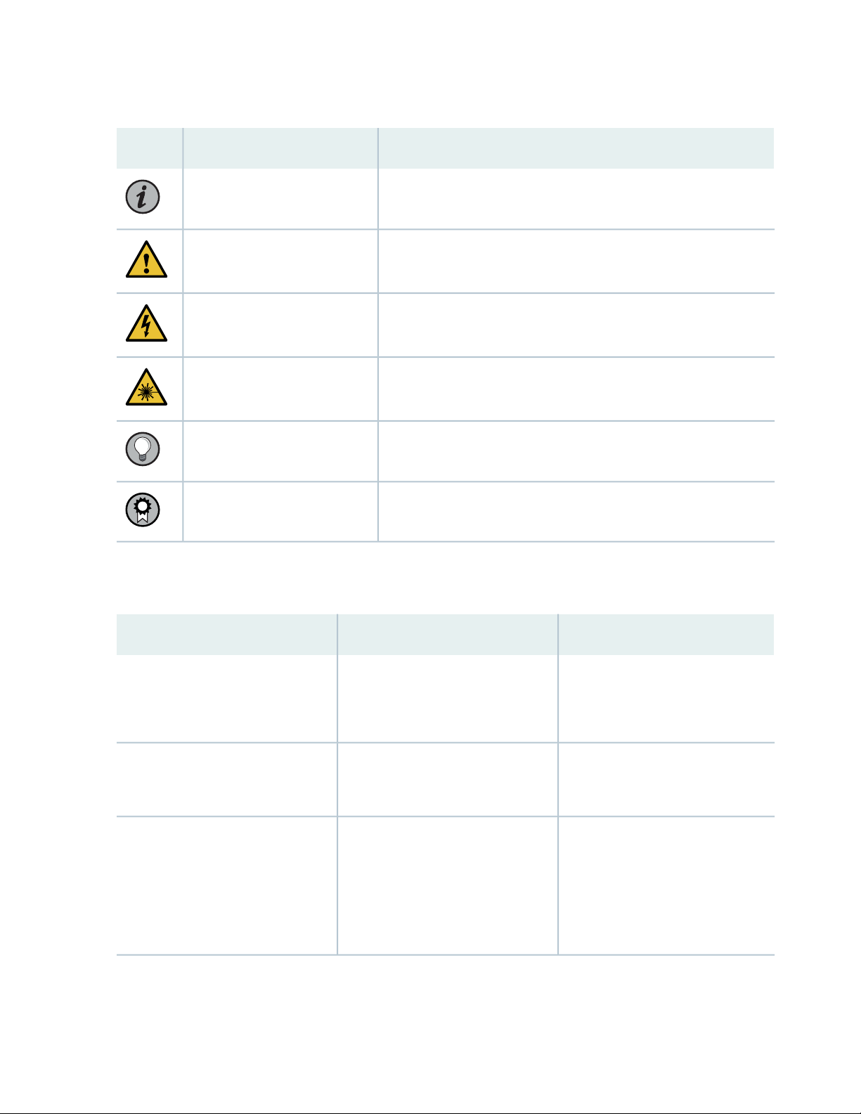
Table 1: Notice Icons
xvi
DescriptionMeaningIcon
Indicates important features or instructions.Informational note
Caution
Indicates a situation that might result in loss of data or hardware
damage.
Alerts you to the risk of personal injury or death.Warning
Alerts you to the risk of personal injury from a laser.Laser warning
Indicates helpful information.Tip
Alerts you to a recommended use or implementation.Best practice
Table 2 on page xvi defines the text and syntax conventions used in this guide.
Table 2: Text and Syntax Conventions
ExamplesDescriptionConvention
Fixed-width text like this
Italic text like this
Represents text that you type.Bold text like this
Represents output that appears on
the terminal screen.
Introduces or emphasizes important
•
new terms.
Identifies guide names.
•
Identifies RFC and Internet draft
•
titles.
To enter configuration mode, type
the configure command:
user@host> configure
user@host> show chassis alarms
No alarms currently active
A policy term is a named structure
•
that defines match conditions and
actions.
Junos OS CLI User Guide
•
RFC 1997, BGP Communities
•
Attribute
Page 17

Table 2: Text and Syntax Conventions (continued)
xvii
ExamplesDescriptionConvention
Italic text like this
Text like this
< > (angle brackets)
| (pipe symbol)
Represents variables (options for
which you substitute a value) in
commands or configuration
statements.
Represents names of configuration
statements, commands, files, and
directories; configuration hierarchy
levels; or labels on routing platform
components.
variables.
Indicates a choice between the
mutually exclusive keywords or
variables on either side of the symbol.
The set of choices is often enclosed
in parentheses for clarity.
Configure the machine’s domain
name:
[edit]
root@# set system domain-name
domain-name
To configure a stub area, include
•
the stub statement at the [edit
protocols ospf area area-id]
hierarchy level.
The console port is labeled
•
CONSOLE.
stub <default-metric metric>;Encloses optional keywords or
broadcast | multicast
(string1 | string2 | string3)
# (pound sign)
[ ] (square brackets)
Indention and braces ( { } )
; (semicolon)
GUI Conventions
Indicates a comment specified on the
same line as the configuration
statement to which it applies.
Encloses a variable for which you can
substitute one or more values.
Identifies a level in the configuration
hierarchy.
Identifies a leaf statement at a
configuration hierarchy level.
rsvp { # Required for dynamic MPLS
only
community name members [
community-ids ]
[edit]
routing-options {
static {
route default {
nexthop address;
retain;
}
}
}
Page 18
Table 2: Text and Syntax Conventions (continued)
xviii
ExamplesDescriptionConvention
Bold text like this
> (bold right angle bracket)
Represents graphical user interface
(GUI) items you click or select.
Separates levels in a hierarchy of
menu selections.
In the Logical Interfaces box, select
•
All Interfaces.
To cancel the configuration, click
•
Cancel.
In the configuration editor hierarchy,
select Protocols>Ospf.
Documentation Feedback
We encourage you to provide feedback so that we can improve our documentation. You can use either
of the following methods:
Online feedback system—Click TechLibrary Feedback, on the lower right of any page on the Juniper
•
Networks TechLibrary site, and do one of the following:
Click the thumbs-up icon if the information on the page was helpful to you.
•
Click the thumbs-down icon if the information on the page was not helpful to you or if you have
•
suggestions for improvement, and use the pop-up form to provide feedback.
E-mail—Send your comments to techpubs-comments@juniper.net. Include the document or topic name,
•
URL or page number, and software version (if applicable).
Requesting Technical Support
Technical product support is available through the Juniper Networks Technical Assistance Center (JTAC).
If you are a customer with an active Juniper Care or Partner Support Services support contract, or are
Page 19

covered under warranty, and need post-sales technical support, you can access our tools and resources
online or open a case with JTAC.
JTAC policies—For a complete understanding of our JTAC procedures and policies, review the JTAC User
•
Guide located at https://www.juniper.net/us/en/local/pdf/resource-guides/7100059-en.pdf.
Product warranties—For product warranty information, visit https://www.juniper.net/support/warranty/.
•
JTAC hours of operation—The JTAC centers have resources available 24 hours a day, 7 days a week,
•
365 days a year.
Self-Help Online Tools and Resources
For quick and easy problem resolution, Juniper Networks has designed an online self-service portal called
the Customer Support Center (CSC) that provides you with the following features:
Find CSC offerings: https://www.juniper.net/customers/support/
•
Search for known bugs: https://prsearch.juniper.net/
•
xix
Find product documentation: https://www.juniper.net/documentation/
•
Find solutions and answer questions using our Knowledge Base: https://kb.juniper.net/
•
Download the latest versions of software and review release notes:
•
https://www.juniper.net/customers/csc/software/
Search technical bulletins for relevant hardware and software notifications:
•
https://kb.juniper.net/InfoCenter/
Join and participate in the Juniper Networks Community Forum:
•
https://www.juniper.net/company/communities/
Create a service request online: https://myjuniper.juniper.net
•
To verify service entitlement by product serial number, use our Serial Number Entitlement (SNE) Tool:
https://entitlementsearch.juniper.net/entitlementsearch/
Creating a Service Request with JTAC
You can create a service request with JTAC on the Web or by telephone.
Visit https://myjuniper.juniper.net.
•
Call 1-888-314-JTAC (1-888-314-5822 toll-free in the USA, Canada, and Mexico).
•
For international or direct-dial options in countries without toll-free numbers, see
https://support.juniper.net/support/requesting-support/.
Page 20

1
CHAPTER
Overview
QFX10016 System Overview | 21
QFX10000 Chassis | 38
QFX10016 Cooling System | 46
QFX10000 AC Power System | 58
QFX10000 DC Power System | 78
QFX10016 Switch Interface Board | 88
QFX10000 Routing and Control Board | 92
QFX10000 Line Cards | 97
Page 21
QFX10016 System Overview
IN THIS SECTION
QFX10016 Hardware Overview | 21
QFX10016 Components and Configurations | 33
QFX10000 Hardware and CLI Terminology Mapping | 35
QFX10000 Component Redundancy | 37
QFX10016 Hardware Overview
21
IN THIS SECTION
Benefits of QFX10000 Modular Chassis Switches | 23
Chassis Description | 24
Routing and Control Board | 27
Line Cards | 28
Switch Interface Boards | 29
Cooling System | 30
Power Supplies | 31
Software | 33
The Juniper Networks QFX10016 modular switch builds a strong underlay foundation for flexible,
high-performance, standards-based fabrics and routing that improve network reliability and agility. The
largest of the QFX10000 line of switches, the QFX10016 can provide 96 Tbps of throughput and 32 Bpps
of forwarding capacity in a 21 rack unit (21 U) chassis. The QFX10016 has 16 slots for line cards that allow
for a smooth transition from 10-Gigabit Ethernet and 40-Gigabit Ethernet networks to 100-Gigabit Ethernet
high-performance networks. Table 3 on page 22 shows the supported port densities.
Page 22

Table 3: QFX10016 Port Densities
MaximumPort Density
230410-Gigabit Ethernet
57640-Gigabit Ethernet
480100-Gigabit Ethernet
The QFX10016 can be deployed in various network designs and fabrics, including:
Layer 3 fabrics
•
Juniper Networks MC-LAG for Layer 2 and 3 networks
•
The QFX10016 is available in both base and redundant configurations for both AC and DC operation. All
systems feature front-to-back airflow. This airflow is also know as airflow out (AFO).
Figure 1 on page 23 shows a front and rear view of the QFX10016.
22
Page 23
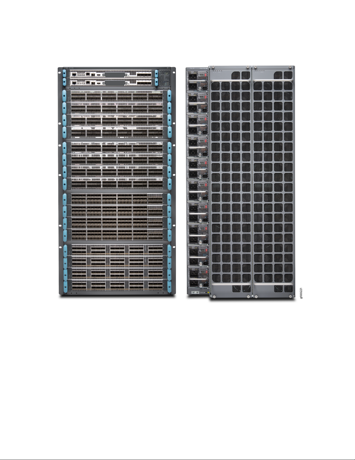
Figure 1: QFX10016—Front and Rear
23
Benefits of QFX10000 Modular Chassis Switches
System throughput—The Juniper Networks®QFX10000 line of modular switches delivers up to 96 Tbps
of system throughput to meet the rapid and ongoing traffic growth in data center, campus, and routing
environments. Industry-leading scale and density on the QFX10000 modular switches redefine per-slot
economics, enabling you to do more with less while simplifying network design and reducing operating
expenditures.
Logical scale—The QFX10000 modular switches deliver the highest Layer 2 / Layer 3 scale with up to 1
million MAC addresses, 2 million host routes, and 2 million FIB. The system also supports deep buffers
Page 24

with up to 100ms packet buffering per port. Virtual output Queue (VoQ) based architecture prevents
head-of-line blocking.
Network architectures—The QFX10000 line can be deployed in a number of different network designs
and fabrics, including IP fabrics and EVPN-VXLAN overlays for Layer 2 and Layer 3 networks, along
with support for DC edge and DCI use cases, giving customers complete architectural flexibility.
Additionally, the open architecture ensures that customers can innovate on top of Juniper Networks
Junos®operating system to accelerate the pace of innovation.
Chassis Description
The QFX10016 is 21 U tall. Two QFX10016 chassis can fit in a standard 42 U rack with adequate cooling
and power. All key QFX10016 components are field-replaceable units (FRUs). Figure 2 on page 25 illustrates
the key components visible from the front and rear of the chassis., Figure 3 on page 26 illustrates the
components that are visible from the rear of the chassis, and Figure 4 on page 27 illustrates the components
that are internal to the chassis.
24
Page 25
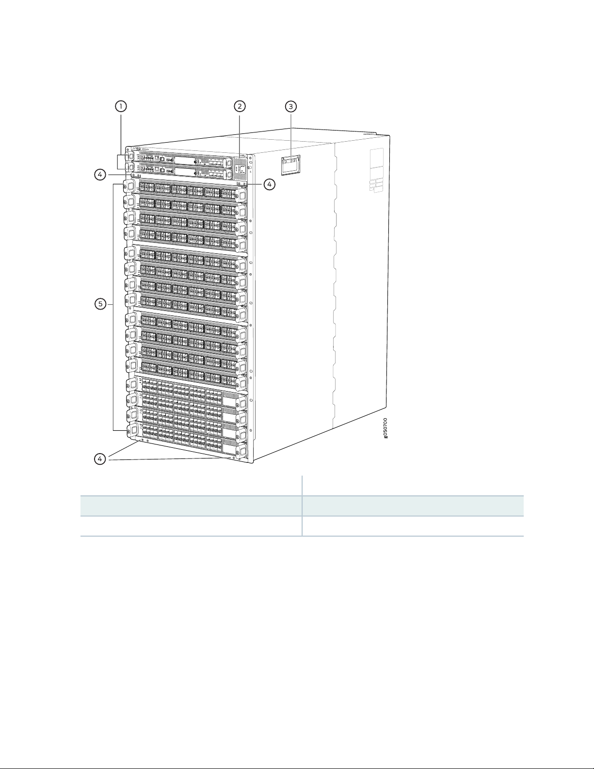
Figure 2: QFX10016 Chassis Front
25
4—1— Installation holes for the front panelRCBs slots 0 and 1 (numbered top to bottom)
5—2— Line card slots 0 to 15 (numbered top to bottom)Status LED panel
3—Handles
Some chassis ship with an enhanced power bus to support the power needs of higher wattage line cards.
Chassis with the enhanced power bus have a modified Status Panel (see QFX10000 Status Panel).
Page 26
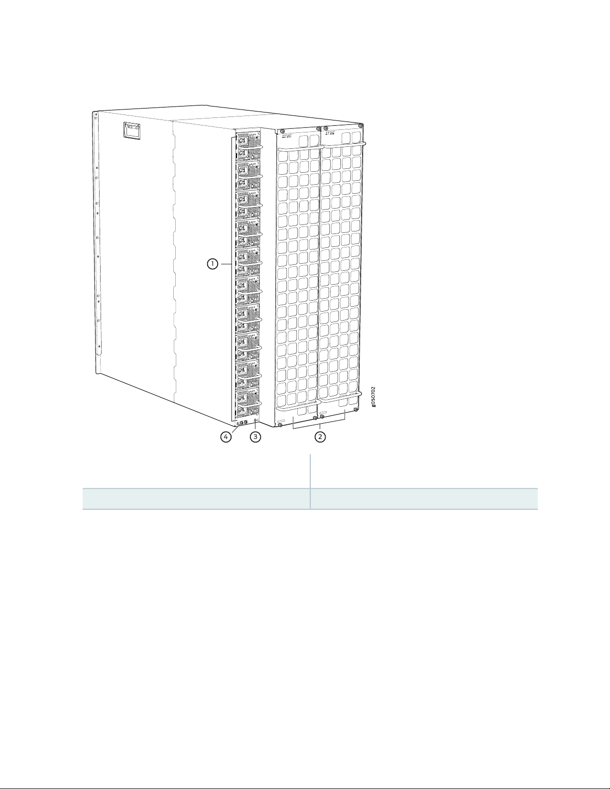
Figure 3: QFX10016 Chassis Rear
26
to bottom)
3—1— ESD pointAC or DC power supplies slots 0 to 9 (numbered top
4—2— Protective earthing terminalFan trays with redundant fans
Page 27
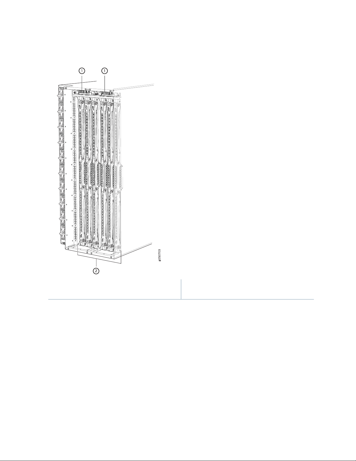
Figure 4: QFX10016 Chassis Internal Components
27
Fan tray controllers slots 0 and 1 (numbered left to
right)
2—1— Switch Interface Boards (SIBs) slots 0 to 5 (numbered
left to right)
See “QFX10016 Chassis Physical Specifications” on page 155 and “QFX10000 Field-Replaceable Units” on
page 39.
Routing and Control Board
The routing and control board (RCB) (see Figure 5 on page 28) contains a Routing Engine and is responsible
for the system management and system control in QFX10016. See “QFX10000 Routing and Control Board
Description” on page 92. RCBs are FRUs that are installed in the front of the chassis in the slots labeled
CB0 and CB1. The base configuration has a single RCB; the fully-redundant configuration has two RCBs.
The RCB also contains Precision Time Protocol (PTP) ports and four Media Access Control Security (MACsec)
capable ports. See “QFX10016 Components and Configurations” on page 33. The base configuration has
a single RCB; the fully redundant configuration has two RCBs.
Page 28
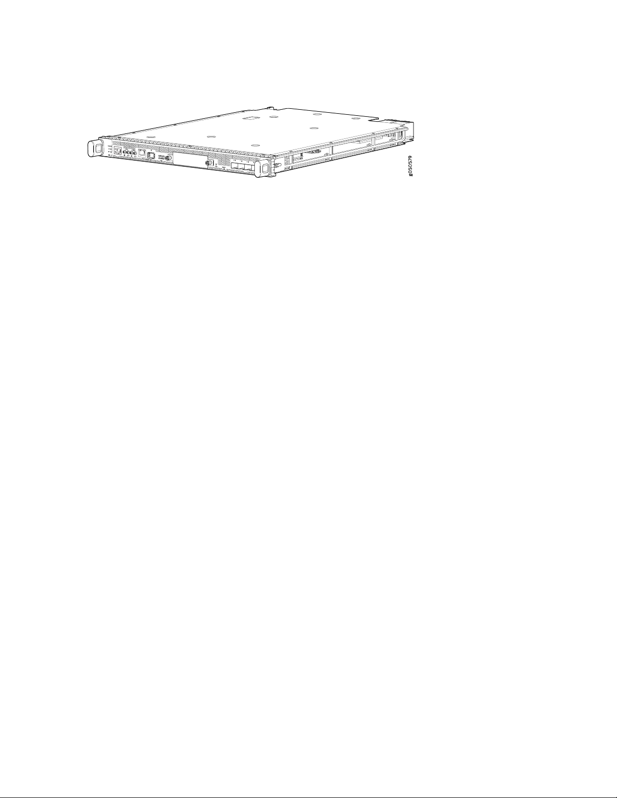
Figure 5: QFX10000 Routing and Control Board (QFX10000-RE)
Line Cards
The QFX10016 features 16 horizontal line card slots and supports line rate for each line card. The line
cards combine a Packet Forwarding Engine (PFE) and Ethernet interfaces enclosed in a single assembly.
The QFX10000 line card architecture is based on a number of identical, independent PFE slices, each with
500 Gbps full-duplex throughput. Line cards are FRUs that can be installed in the line card slots labeled 0
through 15 (top to bottom) on the front of the switch chassis. All line cards are hot-removable and
hot-insertable.
28
Five line cards are available for the QFX10016:
QFX10000-36Q–provides 36 ports of 40-gigabit QSFP+. Twelve ports are designed to be 100-Gigabit
•
capable using QSFP28. Each of the 40-Gigabit QSFP+ can be configured as either a native 40-Gigabit
port or four 10-Gigabit ports using a breakout cable. With breakout cables, the line card supports a
maximum of 144 logical 10-Gigabit Ethernet ports.
QFX10000-30C–provides 30 ports of either 100-gigabit or 40-gigabit QSFP28. The ports autodetect
•
the type of transceiver installed and set the configuration to the appropriate speed. Each of the 40-gigabit
ports can be configured as either a native 40-gigabit port or four 10-gigabit ports using a breakout cable.
With breakout cables, the line card supports a maximum of 96 logical 10-Gigabit Ethernet ports.
QFX10000-30C-M–provides 30 ports of either 100-gigabit or 40-gigabit QSFP28 that support MACsec
•
security features.
QFX10000-60S-6Q–provides 60 SFP+ ports that can be configured for either 1-gigabit or 10-gigabit
•
speeds. The card also provides six flexible configuration ports for 100-gigabit and 40-gigabit speeds. Of
the six flexible configuration ports, two ports have QSFP28 sockets that support either 100-gigabit or
40-gigabit speeds. The remaining four ports have QSFP+ sockets that can be configured as either a
native 40-gigabit port or four 10-gigabit ports using a breakout cable. With breakout cables, the line
card supports a maximum of 84 logical 10-Gigabit Ethernet ports.
QFX10K-12C-DWDM-provides 6 coherent dense wavelength-division multiplexing (DWDM) ports with
•
built-in optics. The card supports MACsec security features and provides a flexible rate modulation at
100 Gbps, 150 Gbps, and 200 Gbps speeds.
See Figure 6 on page 29 for an example of a QFX10000 line card.
Page 29
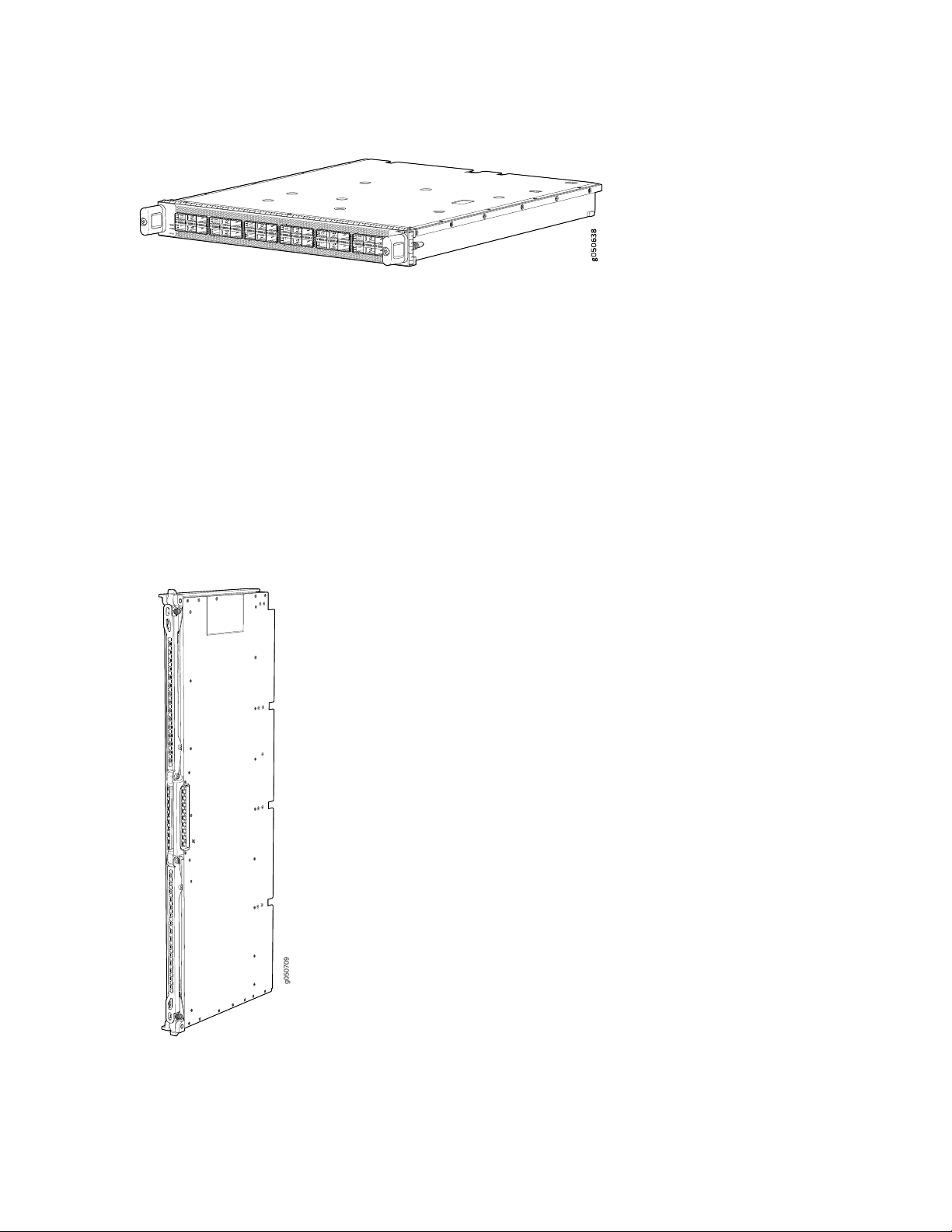
Figure 6: QFX10000-36Q Line Card
g050709
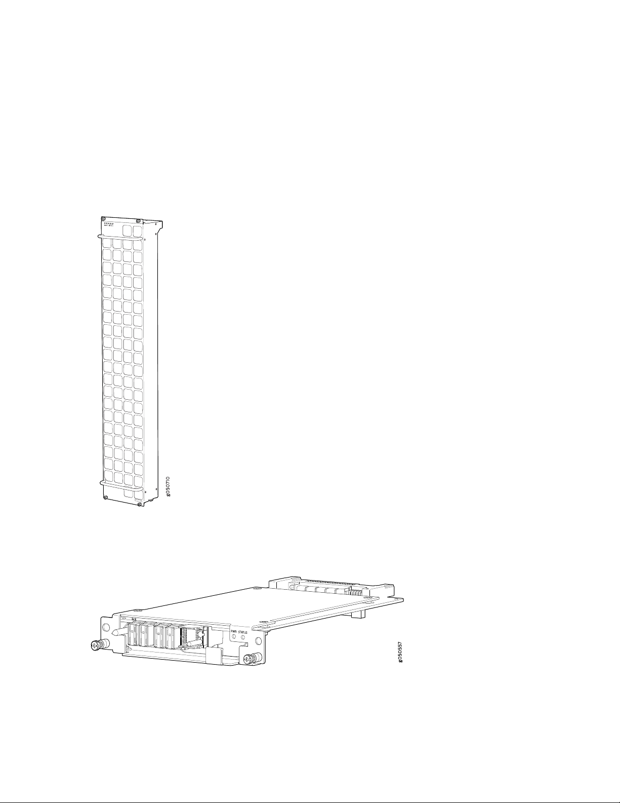
Switch Interface Boards
Five switch interface boards (SIBs) provide the necessary switching functionality to a base configuration
QFX10016. A sixth SIB is available in the redundant configuration to provide n+1 redundancy. SIBs are
installed between the line cards and the fan trays inside of the chassis (see Figure 7 on page 29). Each
QFX10016 SIB has 16 connectors that match to a line card slot, eliminating the need for a backplane.
When all six SIBs are installed, the QFX10016 has a net switching capacity of 96 Tbps. See “QFX10016
Switch Interface Board Description” on page 88.
29
Figure 7: QFX10016 SIB
Page 30
Cooling System
The cooling system in a QFX10016 consists of two hot-removable and hot-insertable FRU fan trays (see
Figure 8 on page 30) and two fan tray controllers (see Figure 9 on page 30). Each fan tray contains 21
fans. The fan trays install vertically on the rear of the chassis and provide front-to-back chassis cooling.
See “QFX10016 Cooling System and Airflow” on page 47.
Figure 8: Fan Tray (QFX10016-FAN)
30
Figure 9: Fan Tray Controller (QFX10016-FAN-CTRL)
Page 31

Power Supplies
The QFX10000 switches support AC, DC, high-voltage alternating current (HVAC) and high-voltage direct
current (HVDC) by offering the following power supplies:
QFX10000-PWR-AC
•
JNP10K-PWR-AC2
•
QFX10000-PWR-DC
•
JNP10K-PWR-DC2
•
All of the power supplies for the QFX10000 are fully redundant, load-sharing, and hot-removable and
hot-insertable FRUs. Each QFX10016 base configuration has five power supplies; redundant configurations
hold the maximum of ten AC HVAC, DC, or HVDC power supplies. Each power supply has an internal fan
for cooling. You can install the power supplies in any slot. See Table 4 on page 31 and Figure 10 on page 32
through Figure 13 on page 33.
The JNP10K-PWR-AC2 and JNP10K-PWR-DC2 PSMs work optimally with the enhanced power bus. To
determine whether your system has the standard power bus or the enhanced power bus, see “QFX10000
Status Panel” on page 40. Table 4 on page 31 provides the specifications for these different power supplies.
31
Table 4: Power Supply Overview
JNP10K-PWR-DC2QFX10000-PWR-DCJNP10K-PWR-AC2QFX10000-PWR-AC
5500 W when set for
high power (80-A) or
4400 W when set for
low power (60-A)
4 DC only (INPUT 1,
INPUT 2)
Standard or enhanced*Standard or enhancedStandard or enhanced
output power
power bus
2700 WMaximum
5500 W, dual feed
when set for high
power (30-A); 3000 W
when set for low
power (20-A)
2 AC only(INP1, INP2)Inputs
Standard or enhancedCompatible
2 AC, HVAC, or HVDC
(INP1, INP2)
*
2500 W5000 W, single feed or
2 DC only (INPUT 1,
INPUT 2)
Note:
*The JNP10K-PWR-AC2 and the JNP10K-PWR-DC2 power supplies are supported on both the standard and enhanced
chassis. However, when these models are run in a standard chassis, the power management software sets the power
budget to 3000 W.
Page 32

CAUTION: Do not mix power supply models in the same chassis in a running
g100585
environment. DC and HVDC can coexist in the same chassis during the hot swap of
DC for HVDC.
Figure 10: QFX10000-PWR-AC Power Supply
32
Figure 11: JNP10K-PWR-AC2 Power Supply
Page 33

Figure 12: QFX10000-PWR-DC Power Supply
g050571
g100595
Figure 13: JNP10K-PWR-DC2 Power Supply
33
Table 4 on page 31 provides an overview of the differences among the power supplies.
Software
The Juniper Networks QFX Series Ethernet Switches run Junos OS, which provides Layer 2 and Layer 3
switching, routing, and security services. The same Junos OS code base that runs on QFX Series switches
also runs on all Juniper Networks EX Series, M Series, MX Series, and T Series routers and SRX Series
Services Gateways. The minimum Junos OS release is 15.1X53-D61.
QFX10016 Components and Configurations
Table 5 on page 34 lists the four hardware configurations for a QFX10016 modular chassis—base (AC
version), and redundant (AC and DC versions)—and the components included in each configuration.
Page 34

Table 5: QFX10016 Hardware Configurations
Configuration ComponentsSwitch Configuration
34
Base AC configuration
QFX10016-BASE
Redundant AC configuration
QFX10016-REDUND
Chassis, including power bus
•
One RCB
•
One RCB cover, SDD coverl
•
Two QFX10016-FAN-CTRL fan tray controllers
•
Two QFX10016-FAN fan trays
•
Five QFX10000-PWR-AC power supplies
•
Five power supply covers
•
Ten AC power cables
•
Five QFX10016-SF Switch Interface Boards (SIBs)
•
One SIB cover
•
Sixteen line card covers
•
One front panel
•
Chassis, including power bus
•
Two RCBs
•
Two QFX10016-FAN-CTRL fan tray controllers
•
Two QFX10016-FAN fan trays
•
Ten QFX10000-PWR-AC power supplies
•
Six QFX10016-SF Switch Interface Boards (SIBs)
•
Twenty power cords
•
Sixteen line card covers
•
One front panel
•
Redundant DC configuration
QFX10016-REDUND-DC
Chassis, including power bus
•
Two RCBs
•
Two QFX10016-FAN-CTRL fan tray controllers
•
Two QFX10016-FAN fan trays
•
Ten QFX10000-PWR-DC power supplies
•
Six QFX10016-SF SIBs
•
Sixteen line card covers
•
One front panel
•
NOTE: You can install up to 8 line cards (any combination of line cards) in the QFX10008 and
16 line cards in the QFX10016.
Page 35

NOTE: Line cards, the cable management system, and the SATA solid state drive are not part
of the base or redundant configurations. You must order them separately.
NOTE: If you want to purchase additional power supplies (AC or DC), SIBs, or RCBs for your
switch configuration, you must order them separately.
SEE ALSO
QFX10016 Chassis Physical Specifications | 155
35
QFX10000 Hardware and CLI Terminology Mapping
This topic describes the hardware terms used in QFX10000 documentation and the corresponding terms
used in the Junos OS CLI. See Table 6 on page 35.
Table 6: CLI Equivalents of Terms Used in Documentation for QFX10000 Switches
Hardware
Item (CLI)
Chassis
Control
Board
QFX10016
CB (n)Routing and
n is a value in the range
of 0–1.
Multiple line items
appear in the CLI if more
than one RCB (CB) is
installed in the chassis.
Item In
DocumentationValue (CLI)Description (CLI)
Switch chassis–QFX10008
Additional Information
QFX10008 Physical
Specifications and
“QFX10016 Chassis
Physical Specifications”
on page 155
“QFX10000 Routing and
Control Board” on
page 92
Page 36

Table 6: CLI Equivalents of Terms Used in Documentation for QFX10000 Switches (continued)
36
Hardware
Item (CLI)
FPC (n)
Xcvr (n)
PSU (n)
Abbreviated name
of the Flexible PIC
Concentrator
(FPC)
On QFX10008 and
QFX10016, an
FPC equates to a
line card.
Abbreviated name
of the transceiver
One of the
following:
QFX10000-PWR-AC
•
QFX10000-PWR-DC
•
JNP10K-PWR-AC2
•
JNP10K-PWR-DC2
•
n is a value in the range
of 0–7 for the QFX10008
and 0–15 for the
QFX10016. The value
corresponds to the line
card slot number in which
the line card is installed.
the number of the port in
which the transceiver is
installed.
n is a value in the range
of 0–5. The value
corresponds to the power
supply slot number.
Item In
DocumentationValue (CLI)Description (CLI)
Line card (The switch
does not have actual
FPCs—the line cards are
the FPC equivalents on
the switch.)
Optical transceiversn is a value equivalent to
AC, DC, HVAC, or
HVDC
Additional Information
Understanding Interface
Naming Conventions
“QFX10000 Optical
Transceiver and Cable
Support” on page 166
QFX10000-PWR-AC
•
Power Supply on
page 59
JNP10K-PWR-AC2
•
Power Supply
QFX10000-PWR-DC
•
Power Supply on
page 79
JNP10K-PWR-DC2
•
Power Supply
Fan tray
JNP10008-FAN2
QFX10016-FAN
Fan tray–QFX10008-FAN
QFX10008 Cooling
System and Airflow
“QFX10016 Cooling
System and Airflow” on
page 47
Page 37

Table 6: CLI Equivalents of Terms Used in Documentation for QFX10000 Switches (continued)
37
Hardware
Item (CLI)
SIB (n)
This field indicates:
State of the
•
fabric plane:
Active
•
Spare
•
Check State
•
Status of the
•
Packet
Forwarding
Engine in each
fabric plane:
Links OK
•
Error
•
of 0–5.
Item In
DocumentationValue (CLI)Description (CLI)
–Value of n is always 0.–PIC (n)
Additional Information
show chassis fabric sibsFabric planen is a value in the range
Understanding Interface
Naming Conventions
QFX10000 Component Redundancy
The QFX10000 is designed so that no single point of failure can cause the entire system to fail. The
following major hardware components in the redundant configuration provide redundancy:
Routing and Control Board (RCB)—The RCB consolidates the Routing Engine function with control plane
•
function in a single unit. The QFX10000 can have one or two RCBs. When two RCBs are installed, one
functions as the primary and the other functions as the backup. If the primary RCB (or either of its
components) fails, the backup can take over as the primary. See “QFX10000 Routing and Control Board
Description” on page 92.
Switch Interface Boards (SIBs)—The QFX10000 has six SIB slots. Five SIBs are required for base operation
•
and the sixth SIB provides n+1 redundancy. All six SIBs are active and can sustain full throughput rate.
The fabric plane can tolerate one SIB failure without any loss of performance. See the QFX10008 Switch
Interface Board Description and “QFX10016 Switch Interface Board Description” on page 88.
Power supplies—The QFX10000 requires three power supplies for minimum operation (two RCBs, two
•
fan trays, six SIBs and no line cards). With additional power supplies, it provides n+1 redundancy for the
system. AC, DC, HVAC, and HVDC systems tolerate a single power supply to fail without system
Page 38

interruption. If one power supply fails in a fully redundant system, the other power supplies can provide
full power to the QFX10000 indefinitely.
The QFX10000 also supports source redundancy. Two sets of lugs are provided for the
QFX10000-PWR-AC cables, four sets of lugs are provided for the JNP10K-PWR-DC2 cables, and two
AC power cords are provided for each JNP10K-PWR-AC2 power supply.
Cooling system—The fan trays have redundant fans, which are controlled by the fan tray controller. If
•
one of the fans fails, the host subsystem increases the speed of the remaining fans to provide sufficient
cooling for the switch indefinitely. See QFX10008 Cooling System and Airflow and “QFX10016 Cooling
System and Airflow” on page 47.
RELATED DOCUMENTATION
QFX10016 Cooling System | 46
QFX10000 Chassis | 38
38
QFX10000 Routing and Control Board Description | 92
QFX10000-PWR-AC Power Supply | 59
QFX10000-PWR-DC Power Supply | 79
QFX10016 Switch Interface Board Description | 88
QFX10000 Chassis
IN THIS SECTION
QFX10000 Field-Replaceable Units | 39
QFX10000 Status Panel | 40
QFX10000 EMI Front Panel | 43
QFX10000 Optional Equipment | 44
Page 39

QFX10000 Field-Replaceable Units
Field-replaceable units (FRUs) are switch components that you can replace at your site. The switch uses
these types of FRUs:
Hot-insertable and hot-removable—You can remove and replace these components without powering
•
off the switch or disrupting the switching function.
Hot-pluggable—You can remove and replace these components without powering off the switch, but
•
the switching function is interrupted until you replace the component.
Table 7 on page 39 lists the FRUs and their types for the QFX10000.
Table 7: FRUs in an QFX10000
TypeFRU
Hot-insertable and hot-removable.Power supplies
39
Routing Control Board (RCB)
Switch Interface Boards (SIBs)
Hot-insertable and hot-removable.Fan tray
Hot-insertable and hot-removable.Fan tray controller
Redundant configuration:
Primary RCB is hot-pluggable.
•
Backup RCB is hot-insertable and hot-removable.
•
Base configuration:
Removal of the RCB will cause the switch to shut down. You can install a
•
replacement RCB in the second slot. The system will restart to elect a primary
and backup. If necessary, you can switch the primary and backup using the
request chassis routing-engine master switch command.
See QFX10008 Configurations and Upgrade Options and “QFX10016 Components
and Configurations” on page 33.
SIBs are hot-insertable and hot-removable. We recommend that you take SIBs
offline before removing them to avoid traffic loss while the switch fabric is being
reconfigured. For example:
Line cards
user@switch> request chassis sib (offline | online) slot slot-number offline
Hot-insertable and hot-removable. We recommend that you take line cards offline
before removing them. For example:
user@switch> request chassis fpc slot slot-number offline
Page 40

Table 7: FRUs in an QFX10000 (continued)
TypeFRU
Hot-insertable and hot-removable.Optical transceivers
See the Hardware Compatibility
Tool.
NOTE: Line cards are not part of the base or redundant configuration. You must order them
separately.
NOTE: If you have a Juniper Care service contract, register any addition, change, or upgrade of
hardware components at https://www.juniper.net/customers/support/tools/updateinstallbase/.
Failure to do so can result in significant delays if you need replacement parts. This note does
not apply if you replace an existing component with the same type of component.
40
QFX10000 Status Panel
The status panel of the QFX10008 and QFX10016 has two purposes:
Shows the overall status of the chassis
•
Indicates the type of power bus internal to the chassis
•
Some chassis ship with an enhanced power bus to support the power needs of higher wattage line cards.
The status panel indicates chassis status through a set of five bi-color LEDs. See Figure 14 on page 41 for
chassis with the original power bus.
Page 41

Figure 14: Status Panel
g100339
Other chassis have the same set of five bi-color LEDs, but also have an azure blue line to indicate the
enhanced power bus (see Figure 15 on page 41).
Figure 15: Status Panel on Chassis with the Enhanced Power Bus
41
Table 8 on page 41 describes the status panel LEDs.
Table 8: Status Panel LEDs in a QFX10000
On steadilyGreenPower supplies
On steadilyYellow
OffNone
DescriptionStateColorName
All of the power supplies are online and
operating normally.
One or more of the power supplies has an
error.
None of the power supplies is receiving
power.
Page 42

Table 8: Status Panel LEDs in a QFX10000 (continued)
42
DescriptionStateColorName
On steadilyGreenFans
On steadilyYellow
OffNone
On steadilyGreenSIBs
On steadilyYellow
The fans and the fan tray controllers are
online and operating normally.
There is an error in a fan or in one of the
fan tray controllers.
The fan tray controllers and fan trays are
not receiving power.
All installed Switch Interface Boards (SIBs)
are online.
There is an error in one or more SIBs.On steadilyYellow
One or more SIBs are offline.OffNone
All installed line cards are online.On steadilyGreenLine cards
One or more line cards have an error
condition.
SEE ALSO
QFX10000 Troubleshooting Resources Overview | 325
QFX10000 Line Cards | 97
One or more line cards are offline.OffNone
All installed RCBs are online.On steadilyGreenRouting Control Boards
One or more RCBs have an error condition.BlinkingYellow
The installed RCBs are offline.OffNone
Page 43

QFX10000 EMI Front Panel
g051042
The QFX10000 modular chassis models come equipped with a screened door, or panel, that provides
additional electromagnetic interference (EMI) protection.
The panel attaches to the front of the chassis and swings open to allow easy access to optics and line
cards, see Figure 16 on page 43 and Table 9 on page 43.
Figure 16: QFX10008 and QFX10016 EMI Front Panels
43
Table 9: QFX10000 EMI Door Specifications
WeightDimensionsModel
12.8 lb22.25 in. H x 17.70 in. W x 6.10 in. DQFX10008
20.3 lb36.43 in. H x 17.70 in. W x 6.10 in. DQFX10016
Page 44
SEE ALSO
Installing the Front Panel on a QFX10000 | 196
QFX10000 Optional Equipment
IN THIS SECTION
QFX10000 Cable Management System | 44
QFX10000 SATA SSD | 45
The QFX10000 line of modular chassis switches supports the following optional equipment and systems:
44
QFX10000 Cable Management System
The QFX10000 cable management system (see Figure 17 on page 44) enables you to route optical cables
away from the line card ports for better airflow through the chassis. Using this optional system also makes
it easier to use cable ties or strips to organize the cabling.
Figure 17: QFX10000 Cable Management System
The cable management system is comprised of a set of handle extensions and a tray that snaps to the
extensions (see Figure 18 on page 45) for an individual line card. The handle extensions can be used with
Page 45
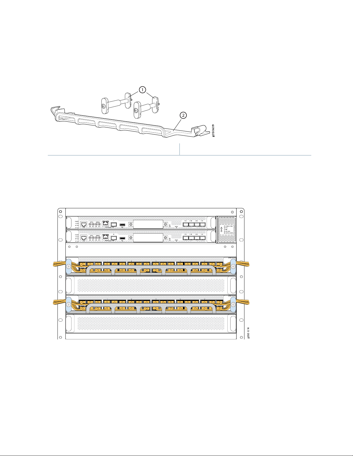
or without the cable tray. It is not necessary to remove the handle extensions if you want to remove a line
g050 614
card.
Figure 18: Cable Management Parts
2—1— Cable trayHandle extensions
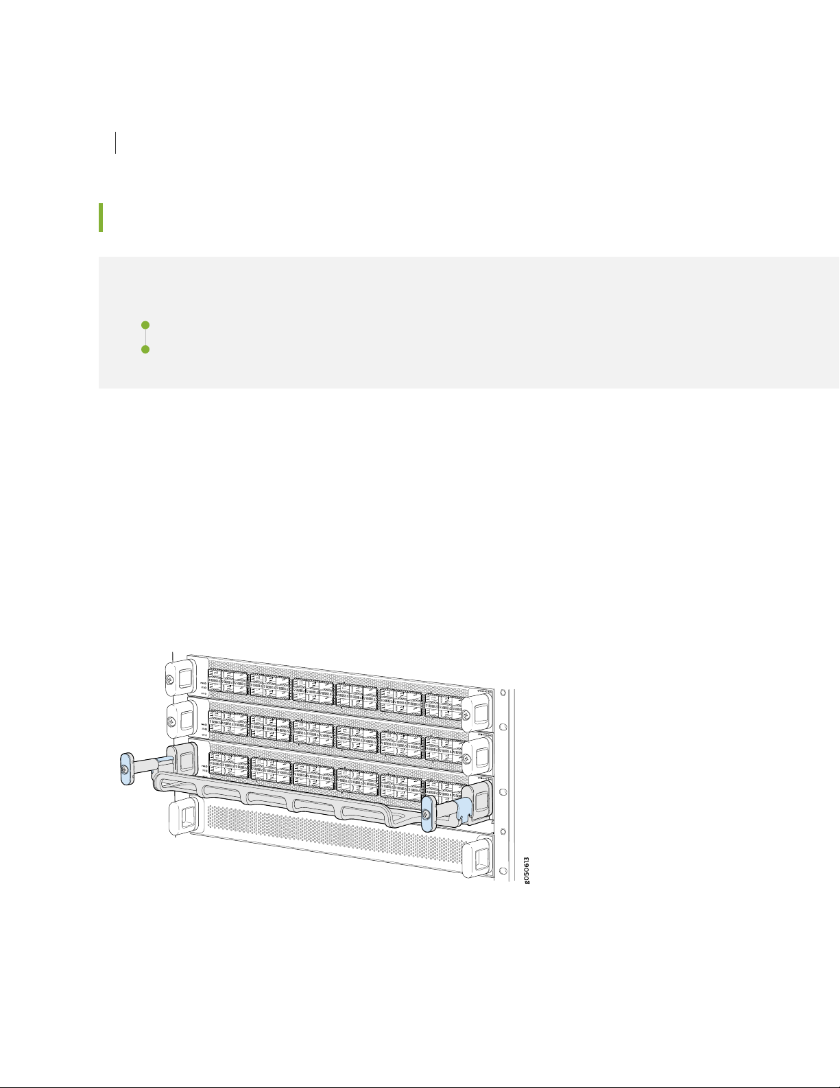
Cables are draped across or under the handle extensions and then secured with cable wraps (see
Figure 19 on page 45).
45
Figure 19: Two Cable Management Systems Installed on QFX10016
QFX10000 SATA SSD
The QFX10000 line of modular chassis switches allows you to install one of two Serial Advanced Technology
Attachment (SATA) solid-state drives (SSDs) as a secondary boot drive or for log storage. The drive is
available in either a 50 GB or 100 GB version. The SATA SSD is field-replaceable unit (FRU) that is installed
in the front panel of a Routing and Control Board (see Figure 20 on page 46).
Page 46

Figure 20: SATA SSD
SEE ALSO
Installing the QFX10000 Cable Management System | 306
Installing the Optional SATA Solid State Drive in a QFX10000 | 297
RELATED DOCUMENTATION
46
QFX10016 Components and Configurations | 33
QFX10000 Optical Transceiver and Cable Support | 166
QFX10016 Cooling System
IN THIS SECTION
QFX10016 Cooling System and Airflow | 47
QFX10000 Fan Tray LEDs and Fan Tray Controller LEDs | 52
The QFX10016 cooling system components work together to keep all components within the acceptable
temperature range. If the maximum temperature specification is exceeded and the system cannot be
adequately cooled, the Routing and Control Board shuts down some or all of the hardware components.
Page 47

QFX10016 Cooling System and Airflow
IN THIS SECTION
Fan Tray QFX10016-FAN | 47
Fan Tray Controller | 49
Airflow Direction in the QFX10016 | 50
The cooling system in a QFX10016 chassis consists of dual fan trays and dual fan tray controllers. There
is no air filter in a QFX10016.
Fan Tray QFX10016-FAN
47
Each fan tray is a hot-insertable and hot-removable FRU. Each fan tray contains 21 fans (0-20), a
non-removable Control Board, and LEDs.
The two fan trays install vertically, side by side, next to the power supplies on the FRU side of the chassis.
Two handles on each front faceplate facilitate handling of the fan tray. See Figure 21 on page 48.
Page 48

Figure 21: Fan Tray QFX10016-FAN
48
See Table 10 on page 48 for the physical specifications for the fan trays.
Table 10: QFX10016-FAN Fan Tray Specifications
ValueSpecification
36.6 in. (92.97 cm)Height
6.6 in. (16.8 cm)Width
4.0 in. (10.2 cm) without handles, 5.3 in. (13.46 cm) with handlesDepth
19.8 lb. (8.98 kg)Weight
Only remove one fan tray when replacing an existing fan tray while the switch is running. The switch
continues to operate for a limited time with a single operating fan tray without triggering a thermal alarm.
CAUTION: To avoid a thermal alarm, do not remove both fan trays while the switch
is operating.
Page 49

CAUTION: The chassis will shut down if a thermal alarm is raised for more than three
minutes.
The internal fan Control Board in each fan tray contains the LEDs for the associated fan tray controllers
and the LEDs for the three SIBs directly behind the fan tray.
Fan Tray Controller
The two fan tray controllers provide the control logic and power to hot-insert and hot-remove a fan tray.
The fans in each fan tray are numbered 0 through 20.
The system continually monitors the temperature of critical parts across the chassis and adjusts the chassis
fan speed according to the temperature.
Software controls the fan speed. Under normal operating conditions, the fans in the fan tray run at less
than full speed. If one fan tray controller fails or appears missing (such as when a SIB is being replaced)
the other fan tray controller sets the fans to full speed. This allows the switch to continue to operate
normally as long as the remaining fans cool the chassis sufficiently. Use the show chassis fan command
to see the status of individual fans and fan speed. For example:
49
user@device> show chassis fan
Item Status RPM Measurement
Fan Tray 0 Fan 0 OK 4500 Spinning at normal speed
Fan Tray 0 Fan 1 OK 4650 Spinning at normal speed
Fan Tray 0 Fan 2 OK 4650 Spinning at normal speed
Fan Tray 0 Fan 3 OK 4800 Spinning at normal speed
Fan Tray 0 Fan 4 OK 4650 Spinning at normal speed
Fan Tray 0 Fan 5 OK 4650 Spinning at normal speed
Fan Tray 0 Fan 6 OK 4650 Spinning at normal speed
Fan Tray 0 Fan 7 OK 4500 Spinning at normal speed
Fan Tray 0 Fan 8 OK 4500 Spinning at normal speed
Fan Tray 0 Fan 9 OK 4650 Spinning at normal speed
Fan Tray 0 Fan 10 OK 4650 Spinning at normal speed
Fan Tray 0 Fan 11 OK 4500 Spinning at normal speed
Fan Tray 0 Fan 12 OK 4500 Spinning at normal speed
Fan Tray 0 Fan 13 OK 4500 Spinning at normal speed
Fan Tray 0 Fan 14 OK 4650 Spinning at normal speed
Fan Tray 0 Fan 15 OK 4350 Spinning at normal speed
Fan Tray 0 Fan 16 OK 4500 Spinning at normal speed
Fan Tray 0 Fan 17 OK 4500 Spinning at normal speed
Fan Tray 0 Fan 18 OK 4350 Spinning at normal speed
Fan Tray 0 Fan 19 OK 4500 Spinning at normal speed
Page 50

Fan Tray 0 Fan 20 OK 4500 Spinning at normal speed
Fan Tray 1 Fan 0 OK 4500 Spinning at normal speed
Fan Tray 1 Fan 1 OK 4650 Spinning at normal speed
Fan Tray 1 Fan 2 OK 4500 Spinning at normal speed
Fan Tray 1 Fan 3 OK 4500 Spinning at normal speed
Fan Tray 1 Fan 4 OK 4650 Spinning at normal speed
Fan Tray 1 Fan 5 OK 4650 Spinning at normal speed
Fan Tray 1 Fan 6 OK 4650 Spinning at normal speed
Fan Tray 1 Fan 7 OK 4500 Spinning at normal speed
Fan Tray 1 Fan 8 OK 4500 Spinning at normal speed
Fan Tray 1 Fan 9 OK 4650 Spinning at normal speed
Fan Tray 1 Fan 10 OK 4500 Spinning at normal speed
Fan Tray 1 Fan 11 OK 4500 Spinning at normal speed
Fan Tray 1 Fan 12 OK 4500 Spinning at normal speed
Fan Tray 1 Fan 13 OK 4650 Spinning at normal speed
Fan Tray 1 Fan 14 OK 4500 Spinning at normal speed
Fan Tray 1 Fan 15 OK 4650 Spinning at normal speed
Fan Tray 1 Fan 16 OK 4650 Spinning at normal speed
Fan Tray 1 Fan 17 OK 4650 Spinning at normal speed
Fan Tray 1 Fan 18 OK 4650 Spinning at normal speed
Fan Tray 1 Fan 19 OK 4500 Spinning at normal speed
Fan Tray 1 Fan 20 OK 4500 Spinning at normal speed
50
user@device>
See Table 11 on page 50 for the physical specifications for the fan tray controllers.
Table 11: Fan Tray Controller QFX100016 FAN Specifications
ValueSpecification
1.5 in. (3.81 cm)Height
6.5 in. (15.24 cm)Width
12.4 in. (31.5 cm)Depth
1.5 lb. (0.68 kg)Weight
Airflow Direction in the QFX10016
The air intake to cool the chassis is located on the port (line card) side of the chassis. Air flows into the
chassis from the ports in the Routing and Control Boards (RCBs) and line cards, through the Switch Interface
Page 51
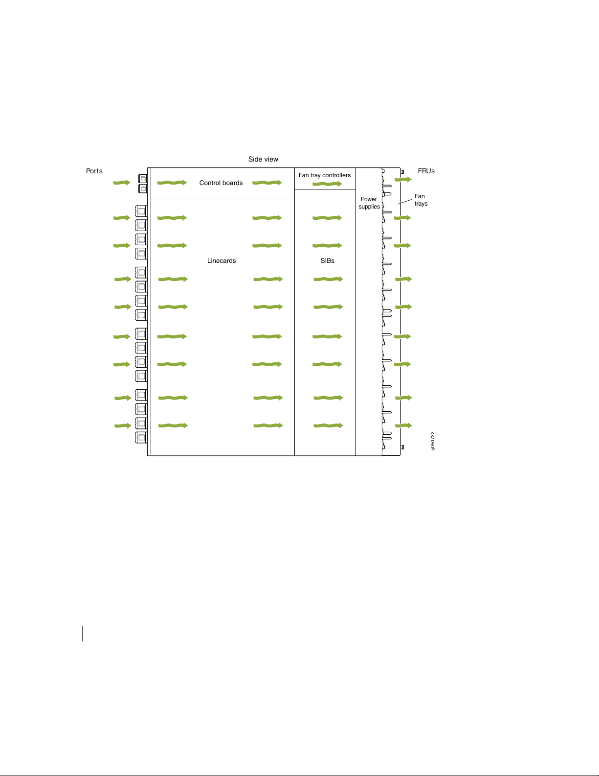
Boards (SIBs), and exits from the fan trays and the power supplies. This airflow is called port-to-FRU cooling
g050722
Side view
FRUsPorts
Control boards
Linecards SIBs
Fan
trays
Fan tray controllers
Power
supplies
or airflow out (AFO). See Figure 22 on page 51.
Figure 22: Airflow Through a QFX10016
51
The fan tray continues to operate indefinitely and provides sufficient cooling even when a single fan fails,
provided the room temperature is within the operating range. You can check the status of fans by viewing
the LEDs on each fan tray.
You cannot replace a single fan. If one or more fans fail, you must replace the entire fan tray.
In addition to the fan trays, there is an internal fan in each power supply.
SEE ALSO
QFX10000 Field-Replaceable Units
Page 52

QFX10000 Fan Tray LEDs and Fan Tray Controller LEDs
IN THIS SECTION
Fan Tray LEDs | 52
Fan Tray Controller LEDs | 56
Each fan tray has a set of LEDs, and each corresponding fan tray controller also has a set of LEDs.
Fan Tray LEDs
The two fan trays have a set of LEDs that represent the status of the fans in the fan tray, the fan tray
controller, and the three Switch Interface Boards (SIBs). The fan tray LEDs are located in the top left corner
of each fan tray. Figure 23 on page 52 shows the location of the LEDs on the QFX10008–FAN and
QFX10016-FAN fan tray.
52
Figure 23: Fan Tray QFX10000-FAN LEDs
Fan status LED
2—Fan tray controller status
3—1— SIB status (SIB 0 through SIB 2 for the left fan tray
and SIB 3 through 5 for the right fan tray)
Table 12 on page 53 describes the functions of the fan tray LEDs.
Page 53

Table 12: Fan Tray LEDs on a QFX10000 Switch
53
DescriptionStateColorName
On steadilyGreenFan status
BlinkingGreen
BlinkingYellow
OffNone
On steadilyGreenFan tray controller status
All fans are operating normally. The system
has verified that the fan tray is engaged,
that the airflow is in the correct direction,
and that all fans are operating correctly.
The beacon feature is enabled. This feature
is enabled using the request chassis
beacon command.
An error has been detected in one or more
fans in the fan tray. Replace the fan tray
as soon as possible. Either the fan has
failed or it has become disconnected. To
maintain proper airflow through the
chassis, leave the fan tray installed in the
chassis until you are ready to replace it.
The fan is not receiving power from the
fan tray controller.
The fan tray controller is online and is
operating normally.
BlinkingGreen
BlinkingYellow
OffNone
The beacon feature is enabled. This feature
is enabled using the request chassis
beacon command.
An error has been detected in the fan tray
controller. Replace the fan tray controller
as soon as possible. The fan tray controller
is located behind the fan tray above the
SIBs. To maintain proper airflow through
the chassis, leave the fan tray installed in
the chassis until you are ready to replace
the fan tray controller.
The fan tray controller is not receiving
power.
Page 54

Table 12: Fan Tray LEDs on a QFX10000 Switch (continued)
54
DescriptionStateColorName
The left-most SIB in the chassis is online.On steadilyGreenSIB 0 status
BlinkingGreen
BlinkingYellow
On steadilyGreenSIB 1 status
BlinkingGreen
The beacon feature is enabled. This feature
is enabled using the request chassis
beacon command.
An error has been detected in SIB 0.
Replace the SIB as soon as possible. The
SIB is located behind the left fan tray and
is the left-most SIB in the chassis. To
maintain proper airflow through the
chassis, leave the fan tray installed in the
chassis until you are ready to replace the
SIB.
The SIB is offline.OffNone
The center SIB behind the left fan tray is
online.
The beacon feature is enabled. This feature
is enabled using the request chassis
beacon command.
BlinkingYellow
An error has been detected in SIB 1.
Replace the SIB as soon as possible. The
SIB is located behind the left fan tray and
is the middle SIB in the grouping of 3. To
maintain proper airflow through the
chassis, leave the fan tray installed in the
chassis until you are ready to replace the
SIB.
The SIB is offline.OffNone
Page 55

Table 12: Fan Tray LEDs on a QFX10000 Switch (continued)
55
DescriptionStateColorName
On steadilyGreenSIB 2 status
BlinkingGreen
BlinkingYellow
On steadilyGreenSIB 3 status
The right-most SIB behind the left fan tray
is online.
The beacon feature is enabled. This feature
is enabled using the request chassis
beacon command.
An error has been detected in SIB 2.
Replace the SIB as soon as possible. The
SIB is located behind the left fan tray and
is the right-most SIB in the grouping of 3.
To maintain proper airflow through the
chassis, leave the fan tray installed in the
chassis until you are ready to replace the
SIB.
The SIB is offline.OffNone
The left-most SIB behind the right fan tray
is online.
BlinkingGreen
BlinkingYellow
The beacon feature is enabled. This feature
is enabled using the request chassis
beacon command.
An error has been detected in SIB 3.
Replace the SIB as soon as possible. The
SIB is located behind the right fan tray and
is the left-most SIB in the grouping of 3.
To maintain proper airflow through the
chassis, leave the fan tray installed in the
chassis until you are ready to replace the
SIB.
The SIB is offline.OffNone
Page 56

Table 12: Fan Tray LEDs on a QFX10000 Switch (continued)
56
DescriptionStateColorName
On steadilyGreenSIB 4 status
BlinkingGreen
BlinkingYellow
On steadilyGreenSIB 5 status
The center SIB behind the right fan tray is
online.
The beacon feature is enabled. This feature
is enabled using the request chassis
beacon command.
An error has been detected in SIB 4.
Replace the SIB as soon as possible. The
SIB is located behind the right fan tray and
is the middle SIB in the grouping of 3. To
maintain proper airflow through the
chassis, leave the fan tray installed in the
chassis until you are ready to replace the
SIB.
The SIB is offline.OffNone
The right-most SIB behind the right fan
tray is online.
BlinkingGreen
BlinkingYellow
The beacon feature is enabled. This feature
is enabled using the request chassis
beacon command.
An error has been detected in SIB 5.
Replace the SIB as soon as possible. The
SIB is located behind the right fan tray and
is the right-most SIB in the grouping of 3.
To maintain proper airflow through the
chassis, leave the fan tray installed in the
chassis until you are ready to replace the
SIB.
The SIB is offline.OffNone
Fan Tray Controller LEDs
The fan tray controller LEDs are only visible when the associated fan tray is removed. The fan tray controller
LEDs are located on the right of the controller panel. Figure 24 on page 57 shows the location of the LEDs
on the QFX10000-FAN-CTRL fan tray controller panel.
Page 57

Figure 24: Fan Tray Controller LEDs on a QFX10000-FAN-CTRL
2—1— Fan tray controller statusFan tray controller power
Table 13 on page 57 describes the functions of the fan tray controller LEDs.
Table 13: Fan Tray Controller LEDs on a QFX100000
DescriptionStateColorName
57
On steadilyGreenFan controller power
BlinkingYellow
OffNone
The fan tray controller has power and is
operating normally.
A power error has been detected in the
fan tray controller. Replace the fan tray
controller as soon as possible. To maintain
proper airflow through the chassis, leave
the fan tray installed in the chassis until
you are ready to replace the fan tray
controller.
The fan tray controller is not powered on
or is not receiving power.
Page 58

Table 13: Fan Tray Controller LEDs on a QFX100000 (continued)
58
DescriptionStateColorName
RELATED DOCUMENTATION
On steadilyGreenFan tray controller status
BlinkingGreen
BlinkingYellow
OffNone
The fan tray controller is online and is
operating normally.
The beacon feature is enabled. This feature
is enabled using the request chassis
beacon command.
An error has been detected in the fan tray
controller. Replace the fan tray controller
as soon as possible. To maintain proper
airflow through the chassis, leave the fan
tray installed in the chassis until you are
ready to replace the fan tray controller.
The fan tray controller is not receiving
power.
Installing a QFX10016 Fan Tray | 226
Installing a QFX10016 Fan Tray Controller | 230
QFX10000 Troubleshooting Resources Overview | 325
QFX10000 AC Power System
IN THIS SECTION
QFX10000-PWR-AC Power Supply | 59
QFX10000-PWR-AC Power Specifications | 62
JNP10K-PWR-AC2 Power Supply | 62
JNP10K-PWR-AC2 Power Specifications | 64
QFX10000 Power Cables Specifications | 65
Page 59

QFX10000 AC Power Supply LEDs | 74
JNP10K-PWR-AC2 Power Supply LEDs | 76
QFX10000-PWR-AC Power Supply
IN THIS SECTION
QFX10000-PWR-AC Power Supply Description | 59
59
QFX10000-PWR-AC Power Supply Description
The QFX10000-PWR-AC power supply is a 2700 W, hot-insertable, hot-removable, field-replaceable unit
(FRU). You can install up to six power supplies in a QFX10008 in the slots labeled PSU 0 through PSU 5
(top to bottom) located in the rear of the chassis. In QFX10016, you can install up to 10 power supplies
in the slots labeled PSU 0 through PSU 9. Power supplies install in any available power supply slot.
The AC power supply supports 200–240 VAC. Each AC power supply has two independent 16 A rated
AC inlets on the faceplate. The output is 12 VDC; the output power is 2700 W.
WARNING: The switch is pluggable type A equipment installed in a restricted-access
location. It has a separate protective earthing terminal on the chassis that must be
connected to earth ground permanently to ground the chassis adequately and protect
the operator from electrical hazards.
CAUTION: Before you begin installing the switch, ensure that a licensed electrician
has attached an appropriate grounding lug to the grounding cable that you supply.
Using a grounding cable with an incorrectly attached lug can damage the switch.
Page 60

NOTE: All base configuration QFX10008 switches are shipped with three power supplies; base
configuration for QFX10016 switches are shipped with five power supplies. Covers are installed
over the remaining power supply slots. You can add additional power supplies to base
configuration switches as necessary. To calculate the number of additional power supplies needed
for your specific system, see Calculating Power Requirements for a QFX10008 and “Calculating
Power Requirements for a QFX10016” on page 159. For details about different switch
configurations, see QFX10008 Configurations and Upgrade Options and “QFX10016 Components
and Configurations” on page 33.
Each QFX10000-PWR-AC power supply weighs approximately 6.8 lb (3.08 kg) and has 2 independent
16 A rated AC inlets on the faceplate. Although each inlet provides sufficient input power to provide full
output, always connect to a dedicated AC power feed to provide redundancy. Only one power feed is
operational at a time.
QFX10000 modular switches employ automatic transfer switch (ATS) technology. The system provides
2n source redundancy and n+1 power supply redundancy, allowing you to use fewer power supplies than
you would require in a 2n configuration. Should one power source fail, ATS switches the power supply to
the alternate source.
60
NOTE: For redundancy, always plug the two power cords from each power supply:
INP1 into a UPS
•
INP2 into the public electricity supply
•
Each QFX10000-PWR-AC power supply has a power switch with international markings for on (|) and off
(O), a fan, and four LEDs on the faceplate that indicate the status of the power supply. See
Figure 25 on page 61.
Page 61

Figure 25: QFX10000-PWR-AC Power Supply
ON
FAULT
PWROK
INP2
INP1
1
2
g050637
Each QFX10000-PWR-AC power supply comes with two power cord retainers that hold the power cords
in place. See Figure 26 on page 61. Each power cord retainer has a clip and an adjustment nut. The ends
of the clip hook into the bracket holes on each side of the AC appliance inlet on the faceplate. The
adjustment nut holds the power cord in the correct position. For instructions for installing the power cord
retainers, see “Connect AC Power to a QFX Modular Chassis” on page 205.
61
Figure 26: Power Cord Retainer for a QFX10000-PWR-AC Power Supply
Each power supply connects to the power rail in the switch. The power rail distributes the output power
produced by the power supplies to different switch components. Each AC power supply provides power
to all the components in the switch.
Each power supply has its own fan and is cooled by its own internal cooling system. Hot air exhausts from
the rear of the chassis.
Page 62

QFX10000-PWR-AC Power Specifications
Table 14 on page 62 lists the power specifications for the AC power supply used in a QFX10000 modular
chassis.
Table 14: Power Specifications for a QFX10000-PWR-AC Power Supply
SpecificationsItem
Operating range: 200–240 VACAC input voltage
50–60 HzAC input line frequency
16 AAC input current rating
2700 WAC output power
Table 15 on page 62 shows the physical specifications for a QFX10000-PWR-AC power supply.
62
Table 15: Physical Specifications for a QFX10000-PWR-AC Power Supply
ValueSpecification
3.5 in. (8.89 cm)Height
3.6 in. (9.14 cm)Width
14.4 in. (6.53 cm)Depth
6.8 lb (3.08 kg)Weight
JNP10K-PWR-AC2 Power Supply
The JNP10K-PWR-AC2 power supply is a high-capacity, high-line model that is designed to support either
AC or DC systems in either a low-power or high-power mode. The power supply takes AC input and
provides DC output of 12.3 VDC, 5000 W with a single feed and 5500 W with a dual feed. For AC systems,
the operating input voltage is 180 to 305 VAC and for DC systems, the operating input voltage is 190 to
410 VDC.
The number of power feeds and whether the power supplies provide high output (30-A) or low output
(20-A) power is configured using a set of dual inline package (DIP) switches on the faceplate of the power
supply. If one power supply in the chassis is set to low power, the power budget for the chassis is reduced
Page 63

to low power, regardless of their DIP switch settings or the output results in CLI. This design safeguards
g100586
JNP10K-PWR-AC2 JNP-PWR-AC
against accidentally setting the power supply to 30-A in a facility that can only provide 20-A and tripping
the facility circuit breaker. We recommend that you do not mix DIP switch settings in your system. See
Table 16 on page 64.
The JNP10K-PWR-AC2 fits into the standard power supply bay but when compared to most other models,
the JNP10K-PWR-AC2 is longer and protrudes from the bay when fully inserted into the chassis. See
Figure 27 on page 63 for the settings for the dip switches.
Figure 27: Comparision of the JNP10K-PWR-AC2 to the QFX10000-PWR-AC Power Supply
63
WARNING: Extreme burn danger–Do not handle an HVAC or HVDC power supply
running in the chassis without heat protective gloves, such as welder’s gloves. The
JNP10K-PWR-AC2 can reach temperatures in the range of 158°F (70°C) to 176°F
(80°C) under running conditions.
WARNING: The switch is pluggable type A equipment installed in a restricted-access
location. It has a separate protective earthing terminal on the chassis that must be
connected to earth ground permanently to ground the chassis adequately and protect
the operator from electrical hazards.
CAUTION: Before you begin installing the switch, ensure that a licensed electrician
has attached an appropriate grounding lug to the grounding cable that you supply.
Using a grounding cable with an incorrectly attached lug can damage the device.
Page 64

CAUTION: Use a 2-pole circuit breaker rated at 25 A in the building installation and
the system, or as per local electrical code.
Table 16: Power Input and Output Voltages for JNP10K-PWR-AC2 Power Supplies
H/L (High Input 30 A/Low Input
20A)INP1 (Switch 2)INP0 (Switch 1)
Output Power
5500 WOn (30 A)OnOn
3000 WOff (20 A)OnOn
5000 WOn (30 A)OffOn
5000 WOn (30 A)OnOff
64
2700 WOff (20 A)OffOn
2700 WOff (20 A)OnOff
CAUTION: It is important to connect both input feeds of the JNP10K-PWR-AC2
power supply to AC mains before loading the system with power.
The JNP10K-PWR-AC2 requires the enhanced power bus to operate at full power. You can use the standard
bus, but available power is 3000 W for power budget from the power management software. To determine
whether your system has the standard power bus or the enhanced power bus, see QFX10000 Status Panel.
JNP10K-PWR-AC2 Power Specifications
The JNP10K-PWR-AC2 power supply supports AC, HVAC, and HVDC.
Table 17 on page 64 lists the power specifications for the JNP10K-PWR-AC power supply.
Table 17: Power Specifications for a JNP10K-PWR-AC2 Power Supply
SpecificationsItem
180–305 VACAC input voltage
Page 65

Table 17: Power Specifications for a JNP10K-PWR-AC2 Power Supply (continued)
SpecificationsItem
190–410 VDCDC input voltage
28.5 AInput current rating
12.3 V, 5500 W with dual feed and 5000 W with single feedDC output power
Table 18 on page 65 shows the physical specifications for a JNP10K-PWR-AC2 power supply.
Table 18: Physical Specifications for a JNP10K-PWR-AC2 Power Supply
ValueSpecification
3.5 in. (8.89 cm)Height
3.6 in. (9.14 cm)Width
65
15.1 in. (38.35 cm)Depth
11.4 lb (5.17 kg)Weight
QFX10000 Power Cables Specifications
IN THIS SECTION
QFX10000-PWR-AC Power Cable Specifications | 66
JNP10K-PWR-AC2 Power Cable Specifications | 68
JNP10K-PWR-AC2 Power Cable Specifications for 30-A Input | 72
Most sites distribute power through a main conduit that leads to frame-mounted power distribution panels,
one of which can be located at the top of the rack that houses the switch. An AC power cord connects
each power supply to the power distribution panel.
Each detachable AC power cord is 8 feet (approximately 2.5 meters) long. The coupler end of the appliance
cord inserts into the AC appliance inlet on the faceplate of the AC power supply. The coupler type is C19
Page 66

as described by the International Electrotechnical Commission (IEC) standard 60320. The plug end of the
power cord fits into the power source outlet that is standard for your geographical location.
NOTE: In North America, AC power cords must not exceed 15 feet (approximately 4.5 meters)
in length, to comply with National Electrical Code (NEC) Sections 400-8 (NFPA 75, 5-2.2) and
210-52 and Canadian Electrical Code (CEC) Section 4-010(3). The cords shipped with the switch
to North America and Canada are in compliance.
QFX10000 AC, high-voltage alternating current (HVAC), and high-voltage direct current (HVDC) have
specific cord requirements. Use the following sections to determine the cable requirements based on the
model of your power supply and any mode settings:
QFX10000-PWR-AC see “QFX10000-PWR-AC Power Cable Specifications” on page 66
•
JNP10K-PWR-AC2 with 20-A input, see “JNP10K-PWR-AC2 Power Cable Specifications” on page 68
•
JNP10K-PWR-AC2 with 30-A input, see “JNP10K-PWR-AC2 Power Cable Specifications for 30-A Input”
•
on page 72
66
QFX10000-PWR-AC Power Cable Specifications
Table 19 on page 67 lists the AC power cord specifications for QFX10000-PWR-AC for various countries
and regions.
Page 67
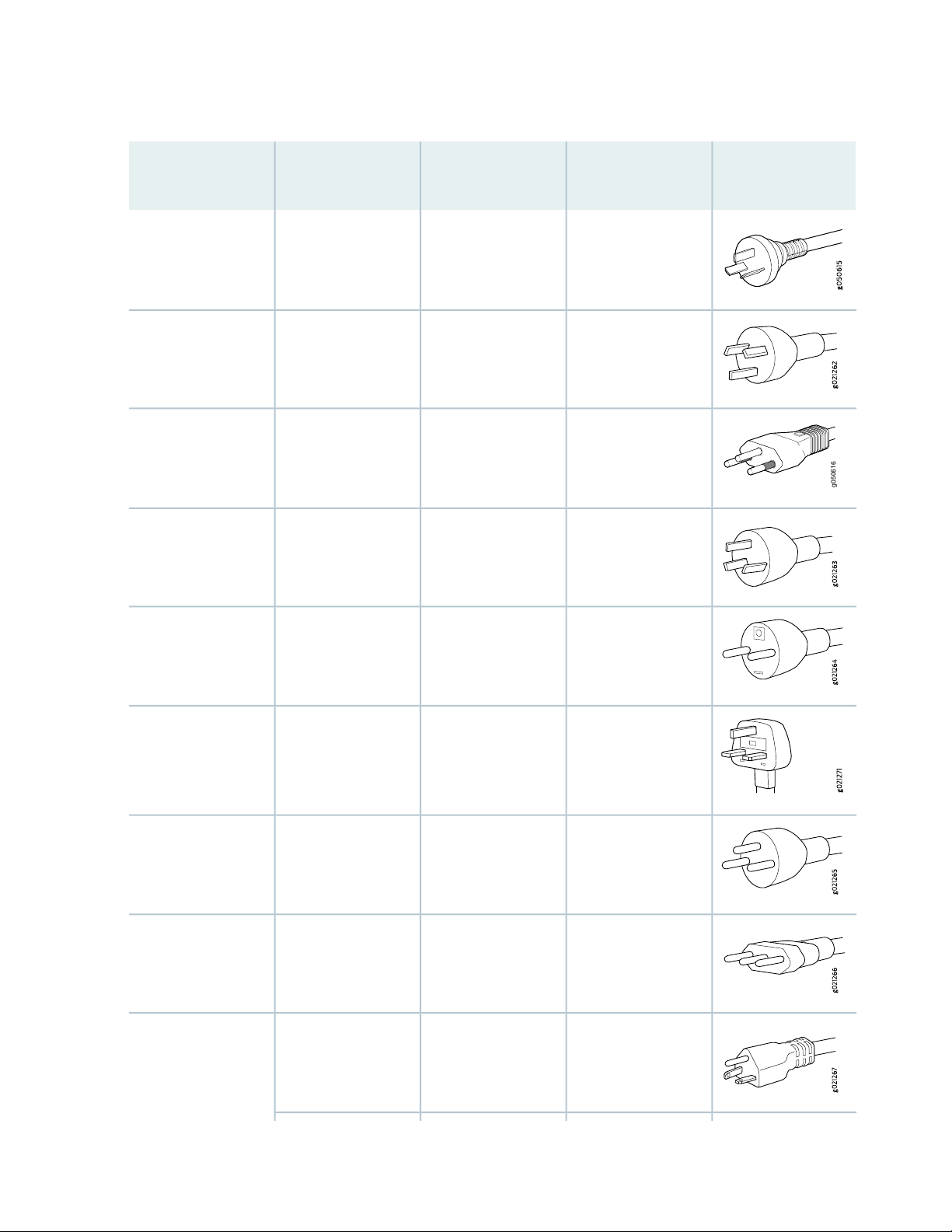
Table 19: AC Power Cord Specifications for QFX10000-PWR-AC Power Supplies
g050616
67
Argentina
Australia
Brazil
China
Electrical
SpecificationsCountry/Region
50 Hz
250 VAC, 15 A,
50 Hz
250 VAC, 16 A,
50 Hz
250 VAC, 16 A,
50 Hz
SAA/3/15
Type BR/3/20
PRC/3/16
Juniper Model
NumberPlug Standards
CBL-EX-PWR-C19-ARIRAM Type RA/3/20250 VAC, 16 A,
CBL-EX-PWR-C19-AUAS/NZS 3112 Type
CBL-EX-PWR-C19-BRNBR 14136: 2002
CBL-EX-PWR-C19-CHGB 1002 Type
Graphic
Europe (except Italy,
Switzerland, and
United Kingdom)
Italy
Japan
50 Hz
250 AC, 16 A, 50 HzIndia
250 VAC, 16 A,
50 Hz
250 VAC, 16 A,
60 Hz
Type ZA/3
I/3/16
NEMA 6–20 Type
N6/20
CBL-EX-PWR-C19-EUCEE (7) VII Type VIIG250 VAC, 16 A,
CBL-EX-PWR-C19-SASABS 164/1:1992
CBL-EX-PWR-C19-ILSI 32/1971 Type IL/3250 AC, 16 A, 50 HzIsrael
CBL-EX-PWR-C19-ITCEI 23-16 Type
CBL-EX-PWR-C19-JP
(default)
Page 68

Table 19: AC Power Cord Specifications for QFX10000-PWR-AC Power Supplies (continued)
g021289
g050751
68
Korea
North America
Electrical
SpecificationsCountry/Region
250 VAC, 16 A,
60 Hz
50 Hz
250 VAC, 16 A,
60 Hz
250 VAC, 16 A,
60 Hz
NEMA Locking
NEMA 6–20 Type
N6/20
NEMA Locking
Juniper Model
NumberPlug Standards
CBL-EX-PWR-C19-JPLNEMA L6–20P Type
CBL-EX-PWR-C19-KRCEE (7) VII Type VIIG250 VAC, 16 A,
CBL-EX-PWR-C19-US
(default)
CBL-EX-PWR-C19-USLNEMA L6–20P Type
Graphic
South Africa
Switzerland
United Kingdom
Worldwide (except
Japan)
250 VAC, 16 A,
50 Hz
250 VAC, 16 A,
50 Hz
250 VAC, 13 A,
50 Hz
50 Hz
CBL-EX-PWR-C19-SASABS 164/1:1992
Type ZA/3
CBL-EX-PWR-C19-SZSEV 5934/2 Type
23G
CBL-EX-PWR-C19-UKBS 1363/A Type
BS89/13
CBL-EX-PWR-C19-C20EN 60320-2-2/1250 VAC, 16 A,
Page 69

JNP10K-PWR-AC2 Power Cable Specifications
The JNP10K-PWR-AC2 power supply operates in two modes:
30-A input with 5500 W output
•
“JNP10K-PWR-AC2 Power Cable Specifications for 30-A Input” on page 72 shows cables and connectors
for 30-A input.
20-A input with 3000 W output
•
Table 20 on page 70 shows cables appropriate for 20-A input.
WARNING: Do not run JNP10K-PWR-AC2 power supplies using 20-A cables if
connected to 30-A input.
69
Page 70

Table 20: JNP10K-PWR-AC2 Power Cable Specifications for 20-A Input
g050616
g100342
Spare Juniper
Model NumberPlug StandardsCord Set RatingLocale
70
Graphic
Zealand
Switzerland, and
United Kingdom)
16 A, 250 VACArgentina
CBL-JNP-SG4-ARIRAM 2073 Type
RA/3
CBL-JNP-SG4-AUAS/NZS 441715 A, 250 VACAustralia and New
16 A, 250 VACBrazil
CBL-JNP-SG4-BRNBR 14136 Type
BR/3
CBL-JNP-SG4-CHGB209916 A, 250 VACChina
CG_CBL-APP-400-02IEC 316P6W20 A, 250 VACEurope (except Italy,
CBL-JNP-SG4-UKBS136313 A, 250 VAC,Great Britain
Page 71

Table 20: JNP10K-PWR-AC2 Power Cable Specifications for 20-A Input (continued)
g050751
g100341
Spare Juniper
Model NumberPlug StandardsCord Set RatingLocale
CBL-JNP-SG4-SASANS 164/116 A, 250 VACIndia
71
Graphic
16 A, RA, 250 VACIsrael
CBL-JNP-SG4-ILSI 32/1971 Type
IL/3G
CBL-JNP-SG4-ITCEI 23-1616 A, 250 VACItaly
20 A, 250 VACNorth America
CBL-JNP-SG4-C20C20 to Anderson
3-5958p4
16 A, 250 VACNorth America
CBL-JNP-SG4-US-LLocking NEMA
L6-20P
CBL-JNP-SG4-USNEMA 6-20P16 A, 250 VACNorth America
CBL-JNP-SG4-HVACNEMA I7-20P15 A, 277 VNorth America
CG_CBL-APP-400-02IEC 320P6W20 A, 250 VNorth America
CBL-JNP-SG4-SASANS 164/116 A, 250 VACSouth Africa
Page 72

Table 20: JNP10K-PWR-AC2 Power Cable Specifications for 20-A Input (continued)
g021289
g100610
Spare Juniper
Model NumberPlug StandardsCord Set RatingLocale
CBL-JNP-SG4-SZCEI 23-5016 A, 250 VACSwitzerland
JNP10K-PWR-AC2 Power Cable Specifications for 30-A Input
72
Graphic
The JNP10K-PWR-AC2 HVAC or HVDC power supplies requires a high-current cable assembly when set
for 30-A input. One end of the cable has an Anderson APP-400 connector, the other end of the cable is
bare wire. See Figure 28 on page 72 and Table 21 on page 73. These cables are separately orderable and
are not shipped automatically with JNP10K-PWR-AC2 orders. An example of the right-angle cable and
connector is shown in Figure 30 on page 74.
For connection to AC systems, Juniper provides a cable with either a NEMA 30-A connector
(Figure 28 on page 72) or an IEC 330P6W connector (Figure 29 on page 73).
Figure 28: NEMA 30-A Connector
Page 73

Figure 29: IEC 330P6W Connector
g100616
Table 21: 30-A Cabling Options
73
power cord
power cord
AC power
cord
AC power
cord
AC power
cord
AC power
cord
AnyHVAC/HVDC
AnyHVAC/HVDC
Continental
Europe
North
America
North
America
North
America
Cord Set
RatingLocale
30- A,
400 VAC
30-A,
400 VAC
30-A 250
VAC
30-A 250
VAC
VAC
VAC
Plug
Standards
UL 950 and
IEC 60950
UL 950 and
IEC 60950
UL 950 and
IEC332P6
UL 950 and
IEC332P6
IEC330P630-A 240
IEC330P630-A 240
Spare Juniper Model
NumberConnector
CBL-PWR2-BAREAnderson/straight to
bare wire
CBL-PWR2-BARE-RAAnderson/right-angle
to bare wire
CBL-PWR2-332P6W-RAAnderson/straight to
IEC 332P6
CBL-PWR2-332P6WAnderson/straight to
IEC332P6
CBL-PWR2-330P6W-RAAnderson/right-angle
to IEC 330P6
CBL-PWR2-330P6WAnderson/straight to
IEC 330P6
AC power
cord
AC jumper
power cord
AC power
cord
North
America
North
America
North
America
30-A 250
VAC
VAC
VAC
UL 498,
IEC5958P4
UL, CSA30-A 400
UL 498, CSA30-A 250
CBL-PWR2-L6-30PAnderson/straight to
L6-30P
CG-CBL-APP-400-02Anderson/straight to
Anderson
CBL-PWR2-L6-30P-RAAnderson/right-angle
to L6-30P
Page 74

Figure 30: Right-Angle, Bare Cable with Anderson Connector
g100600
2
1
3
3—1— White wire–NeutralBlack wire–Return (+)
2—Green wire-Ground
SEE ALSO
74
General Electrical Safety Guidelines and Warnings | 385
QFX10000 AC Power Supply LEDs
The QFX10000-PWR-AC power supply has four LEDs on its faceplate: INP1, INP2, PWR OK, and FAULT.
These LEDs display information about the status of the power supply. See Figure 31 on page 75.
Page 75

Figure 31: LEDs on a QFX10000-PWR-AC, Power Supply in QFX10000 Switches
g050570
1 2 3 4
3—1— INP2–Source input 2FAULT
75
4—2— INP1–Source input 1PWR OK
Table 22 on page 75 describes the LEDs on a QFX10000-AC power supply in QFX10008 and QFX10016
modular chassis.
Table 22: LEDs on a QFX10000-AC Power Supply in a QFX10000
DescriptionStateColorLED
BlinkingYellowINP1 (INP0 in CLI output)
or INP2 (INP1 in CLI
output)
Indicates that the AC power input voltage is not
within normal operating range.
AC is within operating range (200–240 VAC).SolidGreen
The power supply is switched off.UnlitDark
DC power output is within normal operating range.SolidGreenPWR OK
The output is out of the limits.BlinkingYellow
Power supply is functioning normally.UnlitDarkFAULT
SolidRed
Power supply has failed and must be replaced. Or,
only one input is powered and the enabled switch
for the input that is not powered is set to ON. See
“Connect AC Power to a QFX Modular Chassis” on
page 205 for more information about the enable
switches.
Page 76
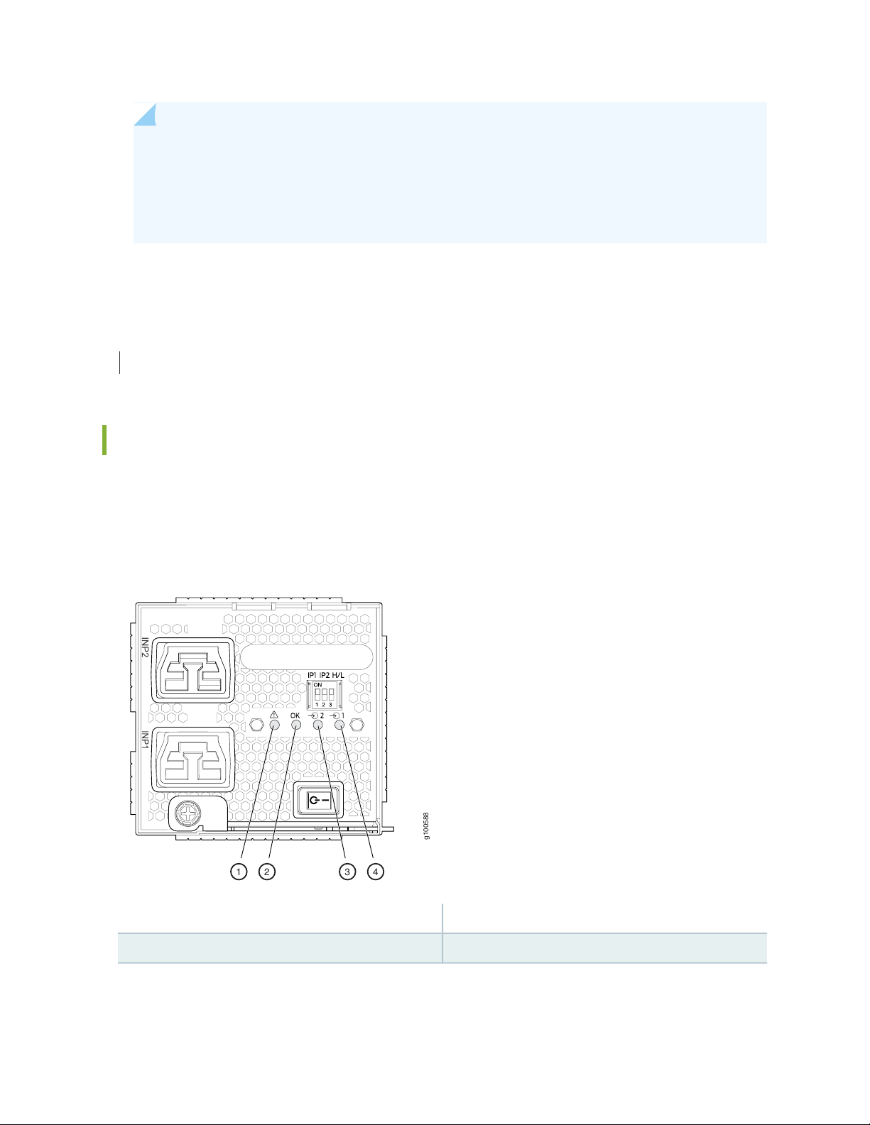
NOTE: If the INP1 or INP2 LED and the PWR OK LED are unlit, the AC power cord is not
g100588
1 2 3 4
installed properly or the power supply has failed.
If the INP1 or INP2 LED is lit and the PWR OK LED is unlit, the AC power supply is not installed
properly or the power supply has an internal failure.
SEE ALSO
Power Requirements for QFX10000 Components
JNP10K-PWR-AC2 Power Supply LEDs
76
The JNP10K-PWR-AC2 power supply has four LEDs on its faceplate: !, OK, 2, and 1. These LEDs display
information about the status of the power supply. See Figure 32 on page 76.
Figure 32: LEDs on a JNP10K-PWR-AC2 HVAC/HVDC Power Supply
3—1— 2 INP2–Source input 1! FAULT
4—2— 1 INP1–Source input 0OK PWR OK
Page 77

NOTE: Physical markings on the power supply are INP1 and INP2. These markings correspond
to INP0 and INP1 in the show chassis power output (see Table 23 on page 77).
Table 23: Physical Markings on Chassis Versus Show Chassis Power Command
Show Chassis Power CommandPhysical Marking on JNP10K-PWR-AC2
INP0INP1
INP1INP2
Table 24 on page 77 describes the LEDs on a JNP10K-PWR-AC2 power supply.
Table 24: Interpreting JNP10K-PWR-AC2 LEDs
DescriptionStateColorLED
77
BlinkingYellowINP1 or INP0 in CLI output
SolidGreen
BlinkingYellowINP2 or INP1 in CLI output
SolidGreen
SolidGreenOK
BlinkingYellow
The input voltage is present, but is not within normal
operating range.
The input voltage is present and within normal
operating range.
The power supply is switched off; voltage is zero.OffUnlit
The input voltage is present, but is not within normal
operating range.
The input voltage is present and within normal
operating range.
The power supply is switched off; voltage is zero.OffUnlit
The power supply output is within normal operating
range.
The power supply output is out of the power limits
or is over-current position.
Power supply has failed and must be replaced.SolidRed!
Power supply is functioning normally.OffUnlit
Page 78

RELATED DOCUMENTATION
Maintaining QFX10000 Power System | 232
Connect AC Power to a QFX Modular Chassis | 205
QFX10000 DC Power System
IN THIS SECTION
QFX10000-PWR-DC Power Supply | 79
QFX10000-PWR-DC Power Specifications | 81
JNP10K-PWR-DC2 Power Supply | 82
JNP10K-PWR-DC2 Power Specifications | 84
78
QFX10000-PWR-DC Power Supply LEDs | 85
JNP10K-PWR-DC2 Power Supply LEDs | 86
The QFX10000 supports three types of DC power supply modules:
QFX10000-PWR-DC—A 2500-W, 12-VDC dual power supply.
•
JNP10K-PWR-DC2—A 5500-W, 12-VDC quad input power supply. For details on this power supply,
•
see “JNP10K-PWR-DC2 Power Supply” on page 82.
JNP10K-PWR-AC2—An AC, high-voltage alternating current (HVAC,) or high-voltage direct current
•
(HVDC) power supply. In high power mode, this power supply provides 12.3 V, 5000 W with a single
feed and 5500 W with dual feeds. For details on this power supply, see “JNP10K-PWR-AC2 Power
Supply” on page 62.
All three power supplies fit into a power slot bay, but the JNP10K-PWR-AC2 and JNP10K-PWR-DC2 are
longer and protrude from the bay when fully inserted into the chassis. See Figure 33 on page 79.
Page 79

Figure 33: Size Comparison Between QFX10000-PWR-DC and JNP10K-PWR-DC2 Power Supplies
g100603
79
QFX10000-PWR-DC Power Supply
CAUTION: Do not mix power supply models in the same chassis in a running
environment. DC and HVDC can coexist in the same chassis during the hot swap of
DC for HVDC.
The QFX10000-PWR-DC power supply is a 2500-W, 12-VDC, dual input power supply. The output of
each QFX10000-PWR-DC power supply is 12-VDC. The output power is 2500 W.
WARNING: The switch is pluggable type A equipment installed in a restricted-access
location. It has a separate protective earthing terminal on the chassis that must be
connected to earth ground permanently to ground the chassis adequately and protect
the operator from electrical hazards.
CAUTION: Before you begin installing the switch, ensure that a licensed electrician
has attached an appropriate grounding lug to the grounding cable that you supply.
Using a grounding cable with an incorrectly attached lug can damage the switch.
Page 80

NOTE: QFX10000-PWR-DC power supplies are shipped only in the redundant configuration
of QFX10000 switches. For details about different chassis configurations, see QFX10008
Configurations and Upgrade Options and “QFX10016 Components and Configurations” on page 33.
Each QFX10000-PWR-DC power supply weighs approximately 6 lb (2.7 kg) and has two independent
pairs of DC input lugs (Input 1, RTN, –48V/–60V and Input 2, RTN, –48V/–60V) on the faceplate of the
power supply. Each inlet requires a dedicated DC power feed. Although each inlet provides sufficient input
power to provide full output, always connect to a dedicated DC power feed to provide redundancy. Only
one power feed is operational at a time.
DC power models employ electronic A-B input selection. It provides 2n source redundancy and n+1 power
supply redundancy using fewer power supplies than you would require in a 2n configuration. Should one
power source fail, electronic A-B input selection switches the power supply to the alternate source.
Each QFX10000-PWR-DC power supply has a power switch with international markings for on (|) and off
(O), a fan, and four LEDs on the faceplate that indicate the status of the power supply. See
Figure 34 on page 80.
80
Figure 34: QFX10000-PWR-DC Power Supply
Page 81

NOTE: The QFX10000-PWR-DC power supply requires a dedicated circuit breaker for each
input DC feed. The chosen breaker should be sized to deliver 60 A of input current.
Each power supply connects to the combined power rail in a QFX10008 or QFX10016. The power rail
distributes the output power produced by the power supplies to different switch components. Each
QFX10000-PWR-DC power supply provides power to all the components in the switch.
NOTE: Ensure that the power cables do not block access to router components or drape where
people can trip on them. Always prevent cables from being exposed to hot air exhaust by routing
them away from the fan trays and power supplies at the rear of the chassis.
A DC power supply can operate with only one input DC feed connected. The RCB only enables the
components for which sufficient power is available.
81
QFX10000-PWR-DC power supplies can use the standard bus or the enhanced bus.
Each QFX10000-PWR-DC power supply has its own fan and is cooled by its own internal cooling system.
The airflow is from the front of the power supply to the back. Hot air exhausts from the rear of the chassis.
QFX10000-PWR-DC Power Specifications
QFX10000-PWR-DC power supplies are supported in only the QFX10008 and QFX10016 redundant
configuration. Table 25 on page 81 lists the power specifications for the QFX10000-PWR-DC power
supply used in a QFX10000 modular chassis.
Table 25: Power Specifications for the QFX10000-PWR-DC Power Supply
SpecificationsItem
DC input voltage
Minimum operating voltage: –40 VDC
•
Nominal operating voltage: –48 VDC
•
Operating voltage range: –40 VDC through –72 VDC
•
DC input current rating
60 A maximum at nominal operating voltage (–48 VDC) for each input
terminal
2500 WOutput power
Table 26 on page 82 shows the physical specifications for a QFX10000-PWR-DC power supply.
Page 82

Table 26: Physical Specifications of a QFX10000-PWR-DC Power Supply
ValueSpecification
3.5 in. (8.89 cm)Height
3.6 in. (9.14 cm)Width
14.4 in. (36.58 cm)Depth
6 lb (2.72 kg)Weight
JNP10K-PWR-DC2 Power Supply
The JNP10K-PWR-DC2 power supply provides two power supplies in a single housing that accepts either
60 A or 80 A using four redundant input power feeds. PS_0 and PS_1 each have redundant input feeds:
A0 and/or B0 for PS_0 and A1 and/or B1 for PS_1. The input is configured using a set of DIP switches on
the power supply faceplate. The output is dependant on the settings of these DIP switches. See
Table 27 on page 82. See Figure 35 on page 83.
82
Table 27: Power Input and Output Voltages for JNP10K-PWR-DC2 Power Supplies
H/L (High Input 80 A/Low Input
60A)INP1 (Switch 2)INP0 (Switch 1)
Output Power
5500 WOn (80 A)OnOn
4400 WOff (60 A)OnOn
2750 WOn (80 A)OffOn
2750 WOn (80 A)OnOff
2200 WOff (60 A)OffOn
2200 WOff (60 A)OnOff
Page 83

Figure 35: JNP10K-PWR-DC2 Power Supply
g100595
CAUTION: Do not mix power supply models in the same chassis in a running
environment. JNP10K-PWR-DC and JNP10K-PWR-DC2 can coexist in the same
chassis during power supply upgrades.
83
WARNING: The router is pluggable type A equipment installed in a restricted-access
location. It has a separate protective earthing terminal on the chassis that must be
connected to earth ground permanently to ground the chassis adequately and protect
the operator from electrical hazards.
CAUTION: Before you begin installing the router, ensure that a licensed electrician
has attached an appropriate grounding lug to the grounding cable that you supply.
Using a grounding cable with an incorrectly attached lug can damage the router.
NOTE: DC power supplies are shipped only in the redundant configuration of QFX10000
switches. For details about different chassis configurations, see QFX10008 Configurations and
Upgrade Options and “QFX10016 Components and Configurations” on page 33.
Chassis with the enhanced bus support the full 5500 W available from the JNP10K-PWR-DC2. Chassis
with the standard bus provides 3000 W for power budget from the power management software. To
determine whether your system has the standard power bus or the enhanced power bus, see QFX10000
Status Panel.
Page 84

JNP10K-PWR-DC2 Power Specifications
Table 28 on page 84 lists the power specifications for the JNP10K-PWR-DC2 power supply used in a
QFX10000 chassis.
Table 28: Power Specifications for the JNP10K-PWR-DC2 Power Supply
SpecificationsItem
84
DC input voltage
DC input current
rating
Output pow er
Minimum operating voltage: –40 VDC
•
Nominal operating voltage: –48 VDC
•
Operating voltage range: –40 VDC through –72 VDC
•
76-A maximum at minimum operating voltage (-40 VDC) with 80-A dip switch setting and
•
5500 W output load.
64-A maximum at nominal operating voltage (–48 VDC) with 80-A dip switch setting and
•
5500 W output load.
60-A maximum at minimum operating voltage (-40 VDC) with 60-A dip switch setting and
•
4400 W output load.
50-A maximum at nominal operating voltage (-48 VDC) with 60-A dip switch setting and
•
4400 W output load.
2200 W for low input (60-A) single feed
4400 W for low input (60-A) dual feed
2750 W for high input (80-A) single feed
5500 W for high input (80-A) dual feed
Table 29 on page 84 shows the physical specifications for a JNP10K-PWR-DC2 power supply.
Table 29: Physical Specifications of a JNP10K-PWR-DC2 Power Supply
ValueSpecification
3.5 in. (8.89 cm)Height
3.6 in. (1.63 cm)Width
16.05 in. (40.77 cm)Depth
8.1 lb (3.67 kg)Weight
Page 85

QFX10000-PWR-DC Power Supply LEDs
A QFX10000-PWR-DC power supply has four LEDs on its faceplate: INP1, INP1, PWR OK, and FAULT.
These LEDs display information about the status of the power supply. See Figure 36 on page 85.
Figure 36: LEDs on a QFX10000-PWR-DC Power Supply in QFX10000 Switches
85
3—1— PWR OKINP1–Source input 1
4—2— FAULTINP2–Source input 2
Table 30 on page 85 describes the LEDs in QFX10008 and QFX10016 modular chassis.
Table 30: LEDs on an QFX10000-PWR-DC Power Supply in QFX10000
DescriptionStateColorLED
BlinkingYellow1 (INP0 in CLI output) or 2
(INP1 in CLI output)
SolidGreen
Indicates the DC power input voltage is not within
normal operating range.
DC power is within operating range (-40 VDC to -72
VDC).
The power supply is switched off.OffUnlit
DC power output is within normal operating range.SolidGreenPWR OK
The output is out of the limits.BlinkingYellow
Page 86

Table 30: LEDs on an QFX10000-PWR-DC Power Supply in QFX10000 (continued)
DescriptionStateColorLED
Power supply has failed and must be replaced.SolidRedFAULT
86
OffUnlit
Power supply is functioning normally. Or, only one
input is powered and the enable switch for the input
that is not powered is set to ON. See “Connect DC
Power to a QFX10008 or QFX10016” on page 205
for more information on the enable switches.
NOTE: If the INP1 or INP2 and the PWR OK LED are unlit, the power cords are not installed
properly or the power supply has failed.
If the INP1 or INP2 LED is lit green and the PWR OK LED is unlit, the power supply is not
installed properly or the power supply has an internal failure.
If the FAULT LED is blinking, add a power supply to balance the power demand and supply.
JNP10K-PWR-DC2 Power Supply LEDs
A JNP10K-PWR-DC2 power supply module has four LEDs on its faceplate: 1, 2, OK, and the symbol for
fault, !. These LEDs display information about the status of the power supply. See Figure 37 on page 87.
Page 87
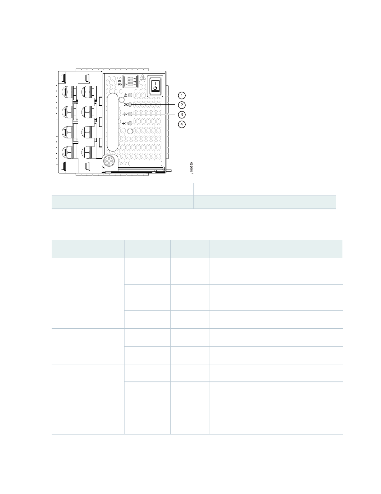
Figure 37: LEDs on a JNP10K-PWR-DC2 Power Supply
g100590
1
2
3
4
3—1— 2–Source input 1!–FAULT
4—2— 1–Source input 0OK–Power okay
87
Table 31 on page 87 describes the LEDs on a JNP10K-PWR-DC2 power supply.
Table 31: LEDs on a JNP10K-PWR-DC2 Power Supply
DescriptionStateColorLED
BlinkingYellow1 (INP0 in CLI output) or 2
(INP1 in CLI output)
SolidGreen
OffUnlit
Indicates the DC power input voltage is not within
normal operating range.
DC power is within operating range (-40 VDC to -72
VDC).
The power supply is switched off.OffUnlit
DC power output is within normal operating range.SolidGreenOK
The output is out of the limits.BlinkingYellow
Power supply has failed and must be replaced.SolidRed!
Power supply is functioning normally. Or, only one
input is powered and the enable switch for the input
that is not powered is set to ON. See “Connecting
the QFX10008 or QFX10016 to Power” on page 201
for more information on the enable switches.
Page 88

NOTE: If the 1 or 2 and the OK LED are unlit, the power cables are not installed properly or the
power supply has failed.
If the 1 or LED is lit green and the OK LED is unlit, the power supply is not installed properly or
the power supply has an internal failure.
If the ! LED is blinking, add a power supply to balance the power demand and supply.
RELATED DOCUMENTATION
Maintaining QFX10000 Power System | 232
Power Requirements for QFX10000 Components
Connect DC Power to a QFX10008 or QFX10016 | 205
88
QFX10016 Switch Interface Board
IN THIS SECTION
QFX10016 Switch Interface Board Description | 88
QFX10000 Switch Interface Board LEDs | 90
QFX10016 Switch Interface Board Description
Switch Interface Boards (SIBs) create the switch fabric for the QFX10016. Each QFX10016 contains six
SIBs that are installed vertically, mid-chassis, between the line cards and the Routing and Control Boards
(RCBs) in the front and the fan trays in the rear. When all six SIBs are installed, the QFX10016 has a net
switching capacity of 96 terabits per second (Tbps).
The SIBs make up the QFX10016 switching plane. Five SIBs are required for operation, with the sixth
providing n+1 redundancy. The sixth SIB is powered and available to the system at all times. Each SIB has
16 connectors that match and connect to a connector on one of the 16 line cards. SIB slots are numbered
0 to 5, numbered from left to right. See Figure 38 on page 89.
Page 89

Figure 38: QFX10016 SIB
g050709
89
Table 32 on page 89 shows the physical specifications for a QFX10016 SIB.
Table 32: Dimensions of a QFX10016 SIB
ValueSpecification
34.6 in. (87.88 cm)Height
1.8 in. (4.57 cm)Width
10.4 in. (26.42 cm)Depth
35.2 lb (15.97 kg)Weight
SIBs are hot-removable and hot-insertable field-replaceable units (FRUs). They are not visible from the
outside of the switch chassis. You must remove one of the fan trays in order to view the SIBs. The SIBs
are numbered from left to right SIB0 to SIB5, with SIB0 located next to the power supplies. See
Figure 39 on page 90.
Page 90
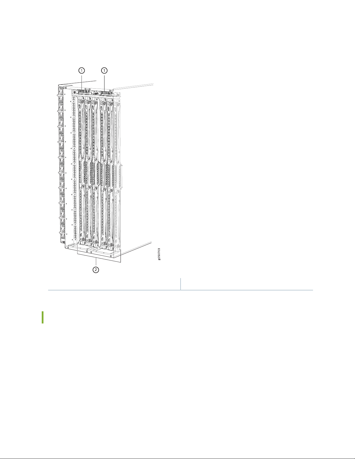
Figure 39: SIBs Installed in a QFX10016
90
2—1— SIBsFan tray controllers
QFX10000 Switch Interface Board LEDs
The Switch Interface Board (SIB) has two status LEDs at the top of each board. See Figure 40 on page 91.
Page 91

Figure 40: SIB LEDs
g050708
1
2
91
Table 33 on page 91 describes the functions of these LEDs.
Table 33: SIB LEDs
DescriptionStateColorLabel
The SIB is receiving power.On steadilyGreenPWR
Power fault.BlinkingYellow
The SIB is either offline or not receiving power.OffUnlit
The SIB is online and functioning normally.On steadilyGreenSTAT
The beacon feature is enabled.BlinkingGreen
The SIB has failed.On steadilyYellow
The fan tray controller is having a power problem.OffUnlit
RELATED DOCUMENTATION
Handling and Storing QFX10000 Line Cards, RCBs, and SIBs | 214
Maintaining QFX10000 Switch Interface Boards | 284
Page 92

QFX10000 Routing and Control Board
IN THIS SECTION
QFX10000 Routing and Control Board Description | 92
QFX10000 Routing and Control Board LEDs | 94
QFX10000 Routing and Control Board Description
IN THIS SECTION
92
RCB Functions | 93
RCB Components | 93
The Routing and Control Board (RCB) is responsible for system management in a QFX10008 or QFX10016
(see Figure 41 on page 92). The switch chassis can run with one or two RCBs. The base configurations
ship with one RCB that can be expanded with a second RCB for a fully-redundant system. When two RCBs
are installed, one functions as the primary and the second as a backup. If the primary RCB is removed, the
backup restarts and becomes the primary.
Figure 41: QFX10000 RCB
This topic covers:
Page 93

RCB Functions
The RCB integrates the control plane and Routing Engine functions into a single management unit. Each
RCB provides all the functions needed to manage the operation of the modular chassis:
System control functions such as environmental monitoring
•
Routing Layer 2 and Layer 3 protocols
•
Communication to all components such as line cards, Switch Interface Boards (SIBs), and power and
•
cooling
Transparent clocking
•
Alarm and logging functions
•
RCB Components
Each RCB consists of the following internal components:
93
Quad-core 2.5 GHz CPU
•
32 GB SDRAM
•
50 GB or 100 GB onboard SATA SSD
•
Other standard interfaces are shown in Figure 42 on page 93.
Figure 42: RCB Faceplate
5—1— USB 2.0 portRCB status LEDs
6—2— SATA SSD slotConsole port
7—3— Reset buttonPTP-capable connections: SMB In, SMB Out, 10 MHz
In, 10 MHz Out
8—4— Four SFP+ ports (reserved for future use)Ethernet management ports: RJ-45 for
10/100/1000 BASE-T (em0) and small-form factor
pluggable (SFP) for fiber (em1). If both copper and
fiber cables are installed, the RJ-45 is the default.
Page 94
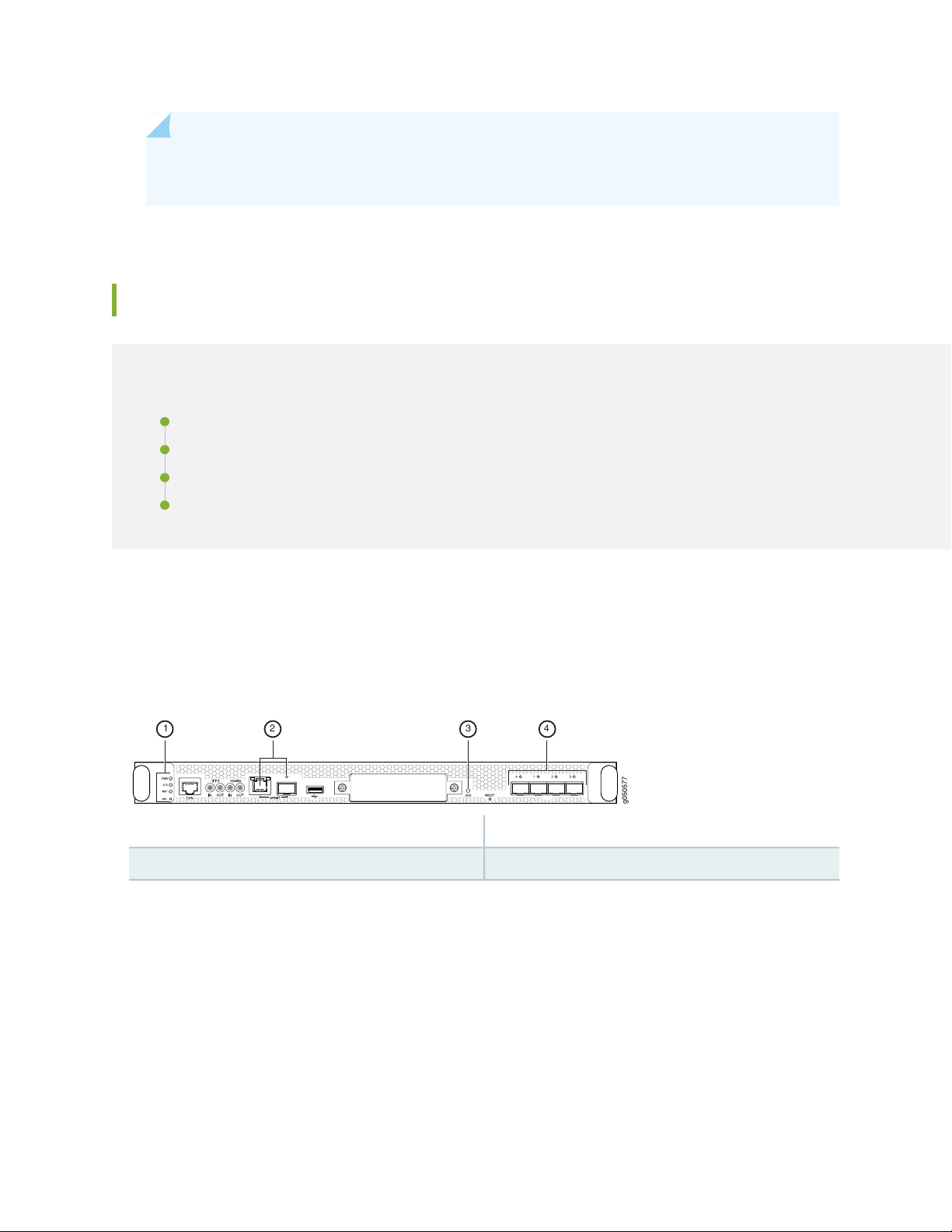
NOTE: You can use either management interface, em0 or em1 when the RCB is running as the
g050577
1 2 3 4
primary RE. Use only em1 when the RCB is running as the backup RE.
QFX10000 Routing and Control Board LEDs
IN THIS SECTION
RCB Status Panel LEDs | 94
QFX10000 Management Port LEDs | 95
SATA SSD LEDs | 97
Virtual Port Connections | 97
94
The QFX10000 Routing and Control Boards (RCBs) have four types of LED indicators (see
Figure 43 on page 94).
Figure 43: QFX10000 RCB LEDs
3—1— SATA SSDRCB status panel
4—2— Virtual port connectionManagement ports
RCB Status Panel LEDs
The RCB status panel LEDs indicate the state of the RCB (see Figure 44 on page 95).
Page 95

Figure 44: RCB Status Panel LEDs
3—1— Primary (MST) LEDPower (PWR) LED
4—2— Offline buttonStatus (STS) LED
Table 34 on page 95 describes the LEDs on the RCB status panel.
Table 34: Routing Control Board Status LEDs
DescriptionStateColorLED
The RCB is receiving adequate power.On steadilyGreenPWR
95
QFX10000 Management Port LEDs
The RCB has detected an error.BlinkingYellow
The RCB is not powered up.UnlitDark
The RCB is online and functioning correctly.On steadilyGreenSTS
The beacon feature is enabled.BlinkingGreen
The RCB is booting.On steadilyYellow
The RCB has detected an error.BlinkingYellow
The power supply is switched off.UnlitDark
The RCB is the primary.On steadilyGreenMST
The RCB is the backup.UnlitDark
There are two management ports on the RCB of a QFX10008 and QFX10016 that have LEDs that indicate
link status and link activity. These two ports, located on the RCB panel between the clocking connections
and the USB port, are both labeled MGMT. The left management port is an SFP cage that can accommodate
up to 1G copper or fiber connections (see Figure 45 on page 96). The copper (RJ-45) port has separate
LEDs for status and activity. The fiber (SFP) port has a combination link and activity LED.
Page 96

Figure 45: Management Port LEDs on a QFX10000
96
Status LED (RJ-45)
2—Activity LED (RJ-45)
3—1— Link LED–Green indicates the link is up; blinking
indicates activity (SFP)
Table 35 on page 96 describes the RJ-45 management port LEDs, and Table 36 on page 96 describes the
SFP status LEDs.
Table 35: RJ-45 Management Port LEDs on a QFX10000 RCB
DescriptionStateColorLED
The port speed is 10 MB.OffUnlitPort speed
The port speed is 100 MB.BlinkingGreen
The port speed is 1000 MB.On steadilyGreen
OffUnlitLink/Activity/Status
No link is established, there is a fault, or the
link is down.
A link is established.On steadilyGreen
Table 36: SFP Management Port LEDs on a QFX10000 RCB
There is link activity.Blinking
The beacon feature is enabled.Blinking or flickeringYellow
DescriptionStateColorLED
No transceiver is present.OffUnlitLink/Activity/Status
A link is established. The interface is up.On steadilyGreen
The beacon feature is enabled.Blinking or flickeringGreen
An error has occurred.BlinkingYellow
Page 97

SATA SSD LEDs
The Serial Advanced Technology Attachment (SATA) solid-state drive (SSD) LEDs indicate the status of
the optional drive.
Table 37 on page 97 describes the LEDs for the optional SATA drive.
Table 37: Control Board Status LEDs
DescriptionStateColorLED
A SATA drive is present.On steadilyGreenSSD
The drive is active.BlinkingGreen
The drive is active.On steadilyYellow
A drive is not installed.UnlitDark
97
Virtual Port Connections
The four small form-factor pluggable plus (SFP+) ports are reserved for future use.
RELATED DOCUMENTATION
Handling and Storing QFX10000 Line Cards, RCBs, and SIBs | 214
Maintaining QFX10000 Routing and Control Boards | 218
Connect a Device to a Network for Out-of-Band Management | 207
QFX10000 Line Cards
IN THIS SECTION
QFX10000-30C Line Card | 98
QFX10000-30C-M Line Card | 102
QFX10000-36Q Line Card | 107
QFX10000-60S-6Q Line Card | 113
Page 98

QFX10K-12C-DWDM Coherent Line Card | 120
1.2-Terabyte Per Second DWDM OTN Module Wavelengths | 127
QFX10000 Line Card LEDs | 145
Offline Button | 146
QFX10000-30C Line Card
IN THIS SECTION
Overview | 98
Channelizing 40-Gigabit Ports | 99
98
Switch Ports | 100
Status and Activity LEDs | 101
The QFX10000-30C line card consists of thirty 28-Gbps QSFP+ Pluggable Solution (QSFP28) cages that
support 40-Gigabit Ethernet or 100-Gigabit Ethernet optical transceivers. The QFX10000-30C ports
automatically detect the type of transceiver installed and set the configuration to the appropriate speed.
The line card can support 10-Gigabit Ethernet by channelizing the 40-Gigabit ports. Channelization is
supported on fiber breakout cable using standard structured cabling techniques.
The QFX10000-30C line card is supported on Junos OS Release 15.1X53-D30 and later. Support for
channelizing the 40-Gigabit Ethernet ports to four independent 10-Gigabit Ethernet ports is supported in
Junos OS Release 17.1R1 and later.
Overview
The line cards in QFX10000 modular switches combine a Packet Forwarding Engine and Ethernet interfaces
in a single assembly. Line cards are field-replaceable units (FRUs) that can be installed in the line card slots
on the front of the switch chassis. The line cards are hot-insertable and hot-removable; you can remove
and replace them without powering off the switch or disrupting switch functions. See Figure 46 on page 99.
Page 99

Figure 46: QFX10000-30C Port Panel
2—1— Network portsPower and status LEDs
Channelizing 40-Gigabit Ports
Beginning with Junos OS Release 17.1R1, 40-Gigabit Ethernet ports on the QFX10000-30C line card can
be channelized to 10-Gigabit Ethernet. When ports are in channelization mode, every fourth port is disabled.
See Figure 47 on page 99 to see which ports are disabled and see Table 38 on page 99 for the maximum
port configurations.
99
Figure 47: Disabled Ports in Channelization Mode
Table 38: Maximum Port Configuration
Channelized Mode (Mode A)Non-Channelized Mode (Mode D)Port Speed
24 or30 or100 Gbps
24 or3040 Gbps
96010 Gbps
Unlike the QFX10000-36C line card, the QFX10000-30C line card does not have port groups; instead,
port behavior is tied to the ASIC associated with the port. You must configure each port individually, in
order to channelize a 40-Gigabit Ethernet port to 4 independent 10-Gigabit Ethernet ports. The first time
a port for an associated ASIC is changed from the default configuration mode (mode D) to the channelization
mode (mode A), the FPC reboots. Subsequent channelization of the ports for that ASIC does not cause
the FPC to reboot. However if one of the channelized ports is changed back to the default, the FPC will
again reboot. See Table 39 on page 100 for the list of available ports and the associated ASIC and
Figure 47 on page 99 to locate the available and disabled ports.
Page 100

CAUTION: Changing the channelization mode (mode D to mode A or mode A to mode
D) causes the FPC to reboot. Because there can be a slight loss of data while the FPC
reboots, we recommend that you only configure the changes during a maintenance
window.
Table 39: Port Mapping for Channelization
100
Disabled PortAvailable PortsASIC
60, 2, 4, 6, 8PE0
71, 3, 5, 7, 9PE1
1610, 12, 14, 16, 18PE2
1711, 13, 15, 17, 19PE3
2620, 22, 24, 26, 28PE4
2721, 23, 25, 27, 29PE5
To change from the default mode to 40-Gigabit Ethernet channelized mode, use the Junos OS operational
command set chassis fpc slot-number pic 0 port port number channelization-speed 10g.
Switch Ports
Each of the 30 QSFP28 ports supports:
100-Gigabit Ethernet using QSFP28 optical transceivers. When a QSFP28 transceiver is inserted into
•
any of the ports, the QSFP28 port is enabled for 100-Gigabit Ethernet.
40-Gigabit Ethernet using QSFP+ optical transceivers. When a QSFP+ transceiver is inserted into any
•
of the ports, the QSFP+ port is enabled for 40-Gigabit Ethernet.
100-Gigabit Ethernet active optic cables (AOC)
•
QSFP28 direct attach copper (DAC) cables
•
QSFP+ DAC cables
•
QSFP+ to SFP+ direct attach copper breakout (DACBO) cables
•
Access ports—You can use 40-Gigabit Ethernet QSFP+ transceivers and QSFP+ DAC cables in any
•
downstream port. See “QFX10000 Optical Transceiver and Cable Support” on page 166.
Uplink ports—You can configure all the QSFP28 ports as uplinks.
•
 Loading...