

Page 1

QFX10002 Switch Hardware Guide
Published
2021-02-22
Page 2

Juniper Networks, Inc.
1133 Innovation Way
Sunnyvale, California 94089
USA
408-745-2000
www.juniper.net
Juniper Networks, the Juniper Networks logo, Juniper, and Junos are registered trademarks of Juniper Networks, Inc. in
the United States and other countries. All other trademarks, service marks, registered marks, or registered service marks
are the property of their respective owners.
Juniper Networks assumes no responsibility for any inaccuracies in this document. Juniper Networks reserves the right
to change, modify, transfer, or otherwise revise this publication without notice.
QFX10002 Switch Hardware Guide
Copyright © 2021 Juniper Networks, Inc. All rights reserved.
The information in this document is current as of the date on the title page.
ii
YEAR 2000 NOTICE
Juniper Networks hardware and software products are Year 2000 compliant. Junos OS has no known time-related
limitations through the year 2038. However, the NTP application is known to have some difficulty in the year 2036.
END USER LICENSE AGREEMENT
The Juniper Networks product that is the subject of this technical documentation consists of (or is intended for use with)
Juniper Networks software. Use of such software is subject to the terms and conditions of the End User License Agreement
(“EULA”) posted at https://support.juniper.net/support/eula/. By downloading, installing or using such software, you
agree to the terms and conditions of that EULA.
Page 3

Table of Contents
1
About the Documentation | x
Documentation and Release Notes | x
Using the Examples in This Manual | x
Merging a Full Example | xi
Merging a Snippet | xii
Documentation Conventions | xii
Documentation Feedback | xv
Requesting Technical Support | xv
Self-Help Online Tools and Resources | xvi
Creating a Service Request with JTAC | xvi
iii
Overview
QFX10002 System Overview | 18
QFX10002 Switch Description | 18
Benefits of the QFX10002 Switch | 19
QFX10002 Models | 19
System Architecture | 21
Cooling and Power | 22
System Software | 23
QFX10002 Hardware Component Overview | 23
QFX10002 Component Redundancy | 23
QFX10002 Field-Replaceable Units | 26
QFX10002 Port Panels | 27
QFX10002-36Q Port Panel | 28
Overview | 28
Network Ports | 29
100-Gbps Operation and Configuration | 30
40-Gbps Channelization | 31
Page 4

Port Mapping | 31
QFX10002-60C Port Panel | 34
Overview | 34
Network Ports | 35
Channelization | 35
QFX10002-72Q Port Panel | 37
Overview | 37
Switch Ports | 38
100-Gbps Operation and Configuration | 39
40-Gbps Channelization | 40
Port Mapping | 40
QFX10002 Network Port LEDs | 45
QFX10002 Management Panel | 47
iv
QFX10002 Management Panel | 47
QFX10002 Management Port LEDs | 50
QFX10002 Chassis Status LEDs | 52
QFX10002 Cooling System | 56
QFX10002 Cooling System and Airflow | 56
Fan Modules | 56
Fan Module Status | 58
QFX10002 Fan Module LED | 59
QFX10002 Power System | 60
QFX10002 AC Power Supply Description | 61
QFX10002 AC Power Specifications | 62
AC Power Cord Specifications for a QFX Series Device | 62
QFX10002 DC Power Supply Description | 65
QFX10002 DC Power Specifications | 66
QFX10002 DC Power Cable Specifications | 67
QFX10002 Power Supply LED | 68
Page 5

Site Planning, Preparation, and Specifications
2
QFX10002 Site Preparation Checklist | 73
QFX10002 Site Guidelines and Requirements | 75
QFX10002 Environmental Requirements and Specifications | 75
General Site Guidelines | 77
QFX10002 Chassis Grounding Cable and Lug Specifications | 77
QFX10002 Clearance Requirements for Airflow and Hardware Maintenance | 78
QFX10002 Chassis Physical Specifications | 79
Site Electrical Wiring Guidelines | 80
QFX10002 Rack Requirements | 80
QFX10002 Cabinet Requirements | 82
QFX10002 Network Cable and Transceiver Planning | 83
v
Determining Transceiver Support for the QFX10002 | 84
Cable Specifications for QSFP+ and QSFP28 Transceivers | 84
Understanding QFX Series Fiber-Optic Cable Signal Loss, Attenuation, and Dispersion | 86
Signal Loss in Multimode and Single-Mode Fiber-Optic Cables | 87
Attenuation and Dispersion in Fiber-Optic Cable | 87
Calculating Power Budget and Power Margin for Fiber-Optic Cables | 88
How to Calculate Power Budget for Fiber-Optic Cable | 88
How to Calculate Power Margin for Fiber-Optic Cable | 89
QFX10002 Management Cable Specifications and Pinouts | 90
Cable Specifications for Console and Management Connections for the QFX Series | 91
RJ-45 Management Port Connector Pinout Information | 91
Console Port Connector Pinout Information | 92
RJ-45 to DB-9 Serial Port Adapter Pinout Information | 93
RJ-45 Port, SFP Port, SFP+ Port, QSFP+ Port, and QSFP28 Port Connector Pinout
Information | 93
USB Port Specifications for the QFX Series | 98
Page 6

Initial Installation and Configuration
3
4
QFX10002 Installation Overview | 101
Overview of Installing the QFX10002 | 101
QFX10002 Installation Safety Guidelines | 102
General Installation Safety Guidelines | 102
QFX10002 Chassis Lifting Guidelines | 103
Unpacking and Mounting the QFX10002 | 103
Unpacking a QFX10002 | 104
Mounting a QFX10002 in a Rack | 105
Before You Begin Rack Installation | 106
Four Post Procedure | 108
Connecting the QFX10002 | 109
vi
Connecting the QFX10002 to Ground | 111
Connecting a QFX10002 to a Management Ethernet Device | 112
Connecting a QFX Series Device to a Management Console | 113
Connecting AC Power to a QFX10002 | 115
Connecting DC Power to a QFX10002 | 117
Register Products—Mandatory to Validate SLAs | 121
Performing an Initial Configuration of a QFX10000 | 121
Maintaining Components
Installing and Removing QFX10002 Hardware Components | 125
Maintaining QFX10002 Cooling System Components | 126
Removing a Fan Module from a QFX10002 | 126
Installing a Fan Module in a QFX10002 | 128
Maintaining QFX10002 Power Supplies | 130
Removing a Power Supply from a QFX10002 | 130
Installing a Power Supply in a QFX10002 | 132
Maintaining Transceivers and Fiber-Optic Cables on QFX10002 | 134
Remove a Transceiver | 134
Install a Transceiver | 138
Page 7

Disconnect a Fiber-Optic Cable | 140
5
6
7
Connect a Fiber-Optic Cable | 141
How to Handle Fiber-Optic Cables | 142
Rebooting or Powering Off a QFX10002 | 143
Rebooting a QFX10002 | 144
Powering Off a QFX10002 | 144
Removing a QFX10002 from a Rack | 147
Troubleshooting
Troubleshooting QFX10002 Components | 150
QFX10002 Troubleshooting Resources Overview | 150
QFX Series Alarm Messages Overview | 151
Chassis Alarm Messages on QFX10002 Switches | 151
vii
Contacting Customer Support and Returning the Chassis or Components
Contact Customer Support | 157
Returning the Chassis or Components | 157
Locating the Serial Number on a QFX10002 or Component | 158
Listing the Chassis and Component Details Using the CLI | 158
Locating the Chassis Serial Number ID Label on a QFX10002 Switch | 160
Locating the Serial Number ID Labels on FRU Components | 160
Removing the Solid State Drives for RMA | 160
Returning a QFX10002 or Component for Repair or Replacement | 163
Packing a QFX10002 or Component for Shipping | 164
Packing a QFX10002 Switch for Shipping | 164
Packing QFX10002 Switch Components for Shipping | 165
Safety and Compliance Information
General Safety Guidelines and Warnings | 168
Definitions of Safety Warning Levels | 169
Qualified Personnel Warning | 172
Warning Statement for Norway and Sweden | 173
Page 8

Fire Safety Requirements | 173
Fire Suppression | 173
Fire Suppression Equipment | 173
Installation Instructions Warning | 175
Chassis and Component Lifting Guidelines | 175
Restricted Access Warning | 177
Ramp Warning | 179
Rack-Mounting and Cabinet-Mounting Warnings | 180
Grounded Equipment Warning | 186
Laser and LED Safety Guidelines and Warnings | 187
General Laser Safety Guidelines | 187
viii
Class 1 Laser Product Warning | 188
Class 1 LED Product Warning | 189
Laser Beam Warning | 190
Radiation from Open Port Apertures Warning | 191
Maintenance and Operational Safety Guidelines and Warnings | 192
Battery Handling Warning | 193
Jewelry Removal Warning | 194
Lightning Activity Warning | 196
Operating Temperature Warning | 197
Product Disposal Warning | 199
General Electrical Safety Guidelines and Warnings | 200
Action to Take After an Electrical Accident | 201
Prevention of Electrostatic Discharge Damage | 202
AC Power Electrical Safety Guidelines | 203
AC Power Disconnection Warning | 205
DC Power Electrical Safety Guidelines | 206
DC Power Copper Conductors Warning | 207
Page 9

DC Power Disconnection Warning | 208
DC Power Grounding Requirements and Warning | 210
DC Power Wiring Sequence Warning | 212
DC Power Wiring Terminations Warning | 215
Multiple Power Supplies Disconnection Warning | 218
TN Power Warning | 219
Agency Approvals and Compliance Statements for the QFX10002 | 219
Agency Approvals for the QFX Series | 220
Compliance Statements for EMC Requirements for the QFX Series | 221
Canada | 221
European Community | 222
ix
Israel | 222
Japan | 222
Korea | 223
Taiwan | 223
United States | 223
Nonregulatory Environmental Standards | 224
Compliance Statements for Acoustic Noise for the QFX Series | 225
Page 10
About the Documentation
IN THIS SECTION
Documentation and Release Notes | x
Using the Examples in This Manual | x
Documentation Conventions | xii
Documentation Feedback | xv
Requesting Technical Support | xv
Use this guide to plan, install, perform initial software configuration, perform routine maintenance, and to
troubleshoot QFX10002 switches.
x
After completing the installation and basic configuration procedures covered in this guide, refer to the
Junos OS documentation for further software configuration.
Documentation and Release Notes
To obtain the most current version of all Juniper Networks®technical documentation, see the product
documentation page on the Juniper Networks website at https://www.juniper.net/documentation/.
If the information in the latest release notes differs from the information in the documentation, follow the
product Release Notes.
Juniper Networks Books publishes books by Juniper Networks engineers and subject matter experts.
These books go beyond the technical documentation to explore the nuances of network architecture,
deployment, and administration. The current list can be viewed at https://www.juniper.net/books.
Using the Examples in This Manual
If you want to use the examples in this manual, you can use the load merge or the load merge relative
command. These commands cause the software to merge the incoming configuration into the current
candidate configuration. The example does not become active until you commit the candidate configuration.
Page 11

If the example configuration contains the top level of the hierarchy (or multiple hierarchies), the example
is a full example. In this case, use the load merge command.
If the example configuration does not start at the top level of the hierarchy, the example is a snippet. In
this case, use the load merge relative command. These procedures are described in the following sections.
Merging a Full Example
To merge a full example, follow these steps:
1. From the HTML or PDF version of the manual, copy a configuration example into a text file, save the
file with a name, and copy the file to a directory on your routing platform.
For example, copy the following configuration to a file and name the file ex-script.conf. Copy the
ex-script.conf file to the /var/tmp directory on your routing platform.
system {
scripts {
commit {
file ex-script.xsl;
}
}
}
interfaces {
fxp0 {
disable;
unit 0 {
family inet {
address 10.0.0.1/24;
}
}
}
}
xi
2. Merge the contents of the file into your routing platform configuration by issuing the load merge
configuration mode command:
[edit]
user@host# load merge /var/tmp/ex-script.conf
load complete
Page 12

Merging a Snippet
To merge a snippet, follow these steps:
1. From the HTML or PDF version of the manual, copy a configuration snippet into a text file, save the
file with a name, and copy the file to a directory on your routing platform.
For example, copy the following snippet to a file and name the file ex-script-snippet.conf. Copy the
ex-script-snippet.conf file to the /var/tmp directory on your routing platform.
commit {
file ex-script-snippet.xsl; }
2. Move to the hierarchy level that is relevant for this snippet by issuing the following configuration mode
command:
[edit]
user@host# edit system scripts
[edit system scripts]
xii
3. Merge the contents of the file into your routing platform configuration by issuing the load merge
relative configuration mode command:
[edit system scripts]
user@host# load merge relative /var/tmp/ex-script-snippet.conf
load complete
For more information about the load command, see CLI Explorer.
Documentation Conventions
Table 1 on page xiii defines notice icons used in this guide.
Page 13
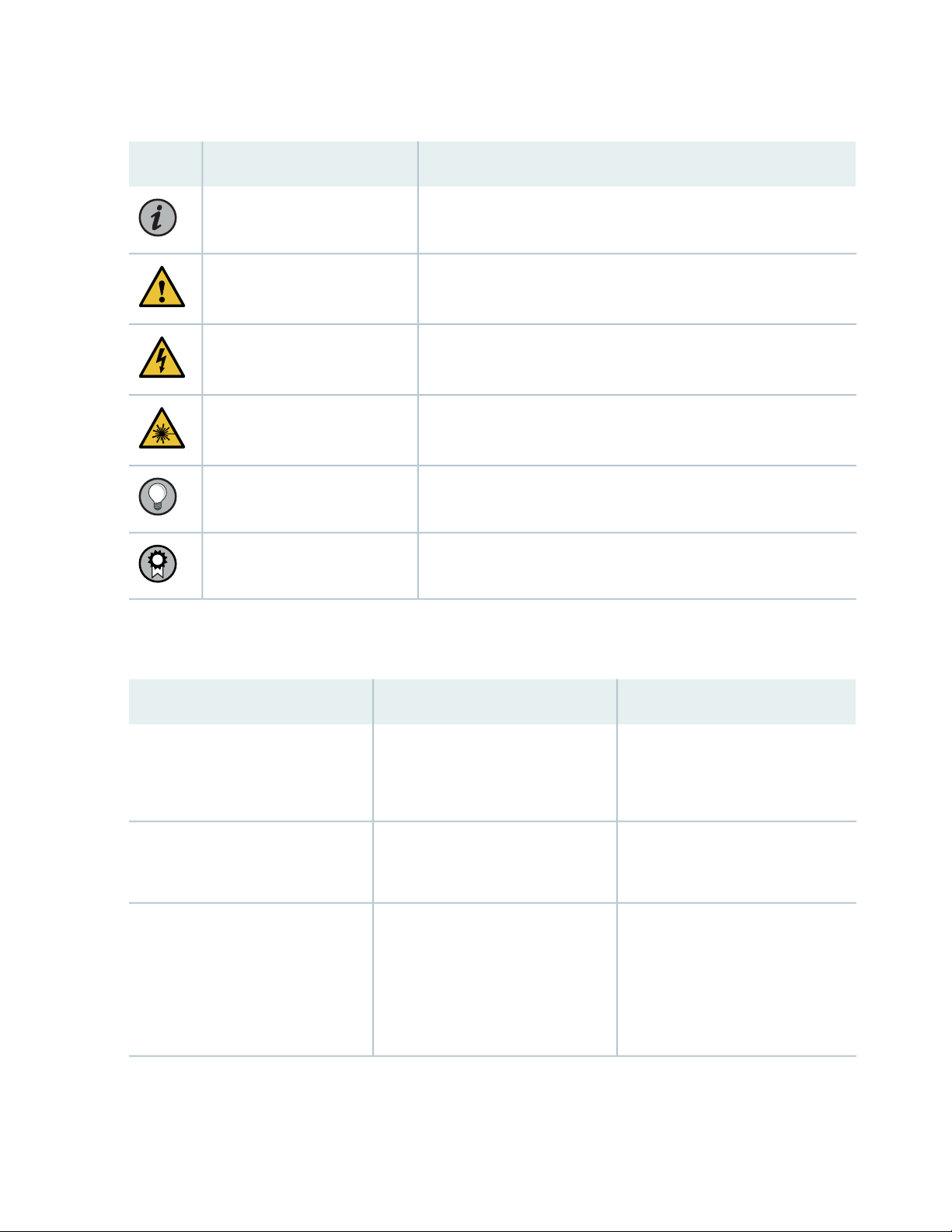
Table 1: Notice Icons
xiii
DescriptionMeaningIcon
Indicates important features or instructions.Informational note
Caution
Indicates a situation that might result in loss of data or hardware
damage.
Alerts you to the risk of personal injury or death.Warning
Alerts you to the risk of personal injury from a laser.Laser warning
Indicates helpful information.Tip
Alerts you to a recommended use or implementation.Best practice
Table 2 on page xiii defines the text and syntax conventions used in this guide.
Table 2: Text and Syntax Conventions
ExamplesDescriptionConvention
Fixed-width text like this
Italic text like this
Represents text that you type.Bold text like this
Represents output that appears on
the terminal screen.
Introduces or emphasizes important
•
new terms.
Identifies guide names.
•
Identifies RFC and Internet draft
•
titles.
To enter configuration mode, type
the configure command:
user@host> configure
user@host> show chassis alarms
No alarms currently active
A policy term is a named structure
•
that defines match conditions and
actions.
Junos OS CLI User Guide
•
RFC 1997, BGP Communities
•
Attribute
Page 14

Table 2: Text and Syntax Conventions (continued)
xiv
ExamplesDescriptionConvention
Italic text like this
Text like this
< > (angle brackets)
| (pipe symbol)
Represents variables (options for
which you substitute a value) in
commands or configuration
statements.
Represents names of configuration
statements, commands, files, and
directories; configuration hierarchy
levels; or labels on routing platform
components.
variables.
Indicates a choice between the
mutually exclusive keywords or
variables on either side of the symbol.
The set of choices is often enclosed
in parentheses for clarity.
Configure the machine’s domain
name:
[edit]
root@# set system domain-name
domain-name
To configure a stub area, include
•
the stub statement at the [edit
protocols ospf area area-id]
hierarchy level.
The console port is labeled
•
CONSOLE.
stub <default-metric metric>;Encloses optional keywords or
broadcast | multicast
(string1 | string2 | string3)
# (pound sign)
[ ] (square brackets)
Indention and braces ( { } )
; (semicolon)
GUI Conventions
Indicates a comment specified on the
same line as the configuration
statement to which it applies.
Encloses a variable for which you can
substitute one or more values.
Identifies a level in the configuration
hierarchy.
Identifies a leaf statement at a
configuration hierarchy level.
rsvp { # Required for dynamic MPLS
only
community name members [
community-ids ]
[edit]
routing-options {
static {
route default {
nexthop address;
retain;
}
}
}
Page 15
Table 2: Text and Syntax Conventions (continued)
xv
ExamplesDescriptionConvention
Bold text like this
> (bold right angle bracket)
Represents graphical user interface
(GUI) items you click or select.
Separates levels in a hierarchy of
menu selections.
In the Logical Interfaces box, select
•
All Interfaces.
To cancel the configuration, click
•
Cancel.
In the configuration editor hierarchy,
select Protocols>Ospf.
Documentation Feedback
We encourage you to provide feedback so that we can improve our documentation. You can use either
of the following methods:
Online feedback system—Click TechLibrary Feedback, on the lower right of any page on the Juniper
•
Networks TechLibrary site, and do one of the following:
Click the thumbs-up icon if the information on the page was helpful to you.
•
Click the thumbs-down icon if the information on the page was not helpful to you or if you have
•
suggestions for improvement, and use the pop-up form to provide feedback.
E-mail—Send your comments to techpubs-comments@juniper.net. Include the document or topic name,
•
URL or page number, and software version (if applicable).
Requesting Technical Support
Technical product support is available through the Juniper Networks Technical Assistance Center (JTAC).
If you are a customer with an active Juniper Care or Partner Support Services support contract, or are
Page 16

covered under warranty, and need post-sales technical support, you can access our tools and resources
online or open a case with JTAC.
JTAC policies—For a complete understanding of our JTAC procedures and policies, review the JTAC User
•
Guide located at https://www.juniper.net/us/en/local/pdf/resource-guides/7100059-en.pdf.
Product warranties—For product warranty information, visit https://www.juniper.net/support/warranty/.
•
JTAC hours of operation—The JTAC centers have resources available 24 hours a day, 7 days a week,
•
365 days a year.
Self-Help Online Tools and Resources
For quick and easy problem resolution, Juniper Networks has designed an online self-service portal called
the Customer Support Center (CSC) that provides you with the following features:
Find CSC offerings: https://www.juniper.net/customers/support/
•
Search for known bugs: https://prsearch.juniper.net/
•
xvi
Find product documentation: https://www.juniper.net/documentation/
•
Find solutions and answer questions using our Knowledge Base: https://kb.juniper.net/
•
Download the latest versions of software and review release notes:
•
https://www.juniper.net/customers/csc/software/
Search technical bulletins for relevant hardware and software notifications:
•
https://kb.juniper.net/InfoCenter/
Join and participate in the Juniper Networks Community Forum:
•
https://www.juniper.net/company/communities/
Create a service request online: https://myjuniper.juniper.net
•
To verify service entitlement by product serial number, use our Serial Number Entitlement (SNE) Tool:
https://entitlementsearch.juniper.net/entitlementsearch/
Creating a Service Request with JTAC
You can create a service request with JTAC on the Web or by telephone.
Visit https://myjuniper.juniper.net.
•
Call 1-888-314-JTAC (1-888-314-5822 toll-free in the USA, Canada, and Mexico).
•
For international or direct-dial options in countries without toll-free numbers, see
https://support.juniper.net/support/requesting-support/.
Page 17

1
CHAPTER
Overview
QFX10002 System Overview | 18
QFX10002 Port Panels | 27
QFX10002 Management Panel | 47
QFX10002 Cooling System | 56
QFX10002 Power System | 60
Page 18
QFX10002 System Overview
IN THIS SECTION
QFX10002 Switch Description | 18
QFX10002 Hardware Component Overview | 23
QFX10002 Component Redundancy | 23
QFX10002 Field-Replaceable Units | 26
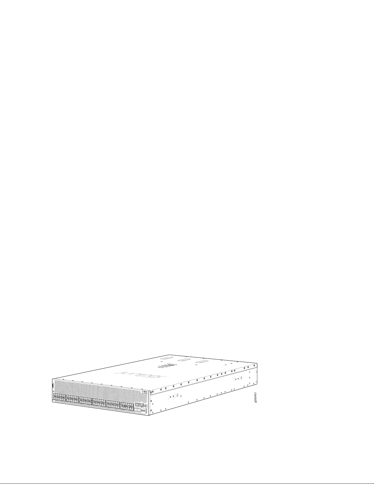
The Juniper Networks QFX10002 fixed configuration switch builds a strong underlay foundation for
flexible, high-performance, standards-based fabrics and routing that improve network reliability and agility.
As part of the QFX10000 line of switches, the QFX10002 models provide the flexibility of 10-Gbps,
40-Gbps, and 100-Gbps port speeds in a 2 U fixed configuration. For more information, see the following
topics:
18
QFX10002 Switch Description
IN THIS SECTION
Benefits of the QFX10002 Switch | 19
QFX10002 Models | 19
System Architecture | 21
Cooling and Power | 22
System Software | 23
The Juniper Networks QFX10002 is a fixed configuration switch that offers a variety of port densities and
network port configurations. This topic covers:
Page 19
Benefits of the QFX10002 Switch
g050401
Combats application latency by using a deep buffer with hybrid memory cube (HMC) technology to
•
absorb network traffic spikes. Deep buffers are important at the edge of data center networks where
typically there is a speed mismatch between WAN-facing interfaces and data center-facing interfaces.
Operates as a universal platform that can be positioned in multiples roles –data center, data center
•
interconnect, or data center edge, as well as campus and routing use cases because of its high logical
scale.
Enables cloud providers to collapse multiple layer in the network (spine and data center interconnect)
•
that offer capital and operational expenditure savings.
Saves on power with an optimized power profile per 100 Gigabit Ethernet.
•
QFX10002 Models
The QFX10002 line of switches are deep-buffer fixed-chassis switches in a 2 U form factor for fixed core
and spine deployments. All models of the QFX10002 support port densities of 10 Gigabit Ethernet, 40
Gigabit Ethernet and 100 Gigabit Ethernet. In addition, all switches are available with either an AC or DC
power supply and with port to field replaceable unit (FRU) cooling. This type of cooling is also known as
airflow out (AFO) or front-to-back cooling. The QFX10002 is available in three port configurations:
19
QFX10002-36Q
•
QFX10002-72Q
•
QFX10002-60C
•
The QFX10002-36Q offers 36 ports of 40-Gigabit Ethernet quad small-form factor plugable (QSFP+) or
12 ports 100-Gigabit Ethernet 28-Gbps QSFP+ Pluggable Solution (QSFP28). The QFX10002-36Q has
up to 2.88 terabits per second (Tbps) of throughput and 1 billion packets per second (Bpps) of forwarding
capacity. This model ships with redundant 1600 W AC or DC power supplies and three fan modules. See
Figure 1 on page 19.
Figure 1: QFX10002-36Q Port Panel
Page 20
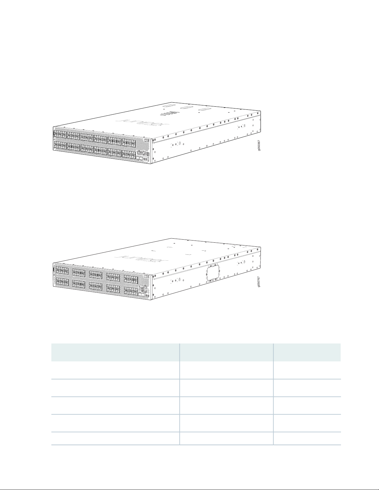
The QFX10002-72Q offers double capacity of the QFX10002-36Q with 72 ports of QSFP+ or 24 ports
g050367
g050767
54
55
49
48
42
13
43
37
36
30
31
7
6
0
1
19
18
18
25
24
of QSFP28. It has up to 5.76 Tbps of throughput and 2 Bpps of forwarding capacity. This model ships with
4 redundant 1600 W AC or DC power supplies and three fan modules. See Figure 2 on page 20.
Figure 2: QFX10002-72Q Port Panel
The QFX10002-60C offers flexible configuration of the 60 QSFP28 ports. Each port can be configured
as either 100 Gbps, 40 Gbps, or 4 by 10 Gbps. It has up to 12 Tbps of throughput and 4 Bpps of forwarding
capacity. The QFX10002-60C ships with four 1600 W AC or DC power supplies and three fan modules.
See Figure 3 on page 20.
20
Figure 3: QFX10002-60C Port Panel
Table 3 on page 20 lists the ordering numbers for QFX10002 devices. See Figure 1 on page 19 through
Figure 3 on page 20 for illustrations of the models.
Table 3: QFX10002 Switch Product Numbers
Power SupplyPortsProduct Numbers
AC72 QSFP+QFX10002-72Q
DC72 QSFP+QFX10002-72Q-DC
AC60 QSFP28QFX10002-60C
DC60 QSFP28QFX10002-60C-DC
AC36 QSFP+QFX10002-36Q
Page 21

Table 3: QFX10002 Switch Product Numbers (continued)
Power SupplyPortsProduct Numbers
DC36 QSFP+QFX10002-36Q-DC
The QFX10002 models feature PHY-less interfaces to save on power and to lower latency. The ports on
all models support quad small-form factor pluggable (QSFP+) transceivers and the 28-Gbps QSFP+ Pluggable
Solution (QSFP28) transceivers. The interfaces on a QFX10002 can be configured to support 10-Gbps,
40-Gbps, and 100-Gbps port speeds. See Table 4 on page 21.
Table 4: Port Capacities
QFX10002-72QQFX10002-60CQFX10002-36Q
28819214410 Gigabit Ethernet
72603640 Gigabit Ethernet
21
246012100 Gigabit Ethernet
System Architecture
The system architecture cleanly separates control operations from packet forwarding operations. This
design eliminates processing and traffic bottlenecks, permitting the QFX10002 to achieve high performance.
Control operations are performed by the Routing Engine, which runs the Juniper Networks Junos
•
operating system (Junos OS). The Routing Engine handles routing protocols, traffic engineering, policy,
policing, monitoring, and configuration management. Junos OS is installed on the QFX10002 internal
solid-state drives (SSDs). QFX10002-36Q and QFX10002-72Q have 2 x 32-GB SSD and the
QFX10002-60C has 2 x 64-GB SSDs. The Routing Engine has a 2.5-GHz quad core Intel CPU and has
16 GB of SDRAM on the QFX10002-36Q and QFX10002-72Q. There is 32 GB of SDRAM on the
QX10002-60C.
Forwarding operations are performed by the Packet Forwarding Engines, which include custom ASICs
•
designed by Juniper Networks. The Q5 ASICs enable the QFX10002 to provide up to 2.88 terabits per
second (Tbps) of throughput on the QFX10002-36Q, 5.76 Tbps on the QFX10002-72Q and 12 Tbps
on the QFX10002-60C. The Q5 ASICs are connected to Hybrid Memory Cubes (HMCs). These
high-efficiency memory modules provide packet buffering, virtual output queue (VOQ) memory, and
improved logical system scale.
Page 22
Cooling and Power
ACINPUT: 100-240V- 60-50Hz14A
DCINPUT: -48VTO-60V ---40A
(FOREACH POWERSUPPLY)
g050372
1 2 3
The cooling system in a QFX10002 consists of three 80-W fan modules that operate at 150 cubic feet
per minute (CFM) at full speed as well as fans housed in the power supplies. Each fan modules has dual
counter-rotating fans. These fan modules can be hot-swapped and hot-inserted, meaning that– you do
not need to power off the switch or disrupt the switching function to replace a module.
in the QFX10002 cooling system, cool air enters through the vents in the port panel and hot air exhausts
through the field-replaceable unit (FRU) panel. This type of airflow is known as airflow out or port-to-FRU
airflow.
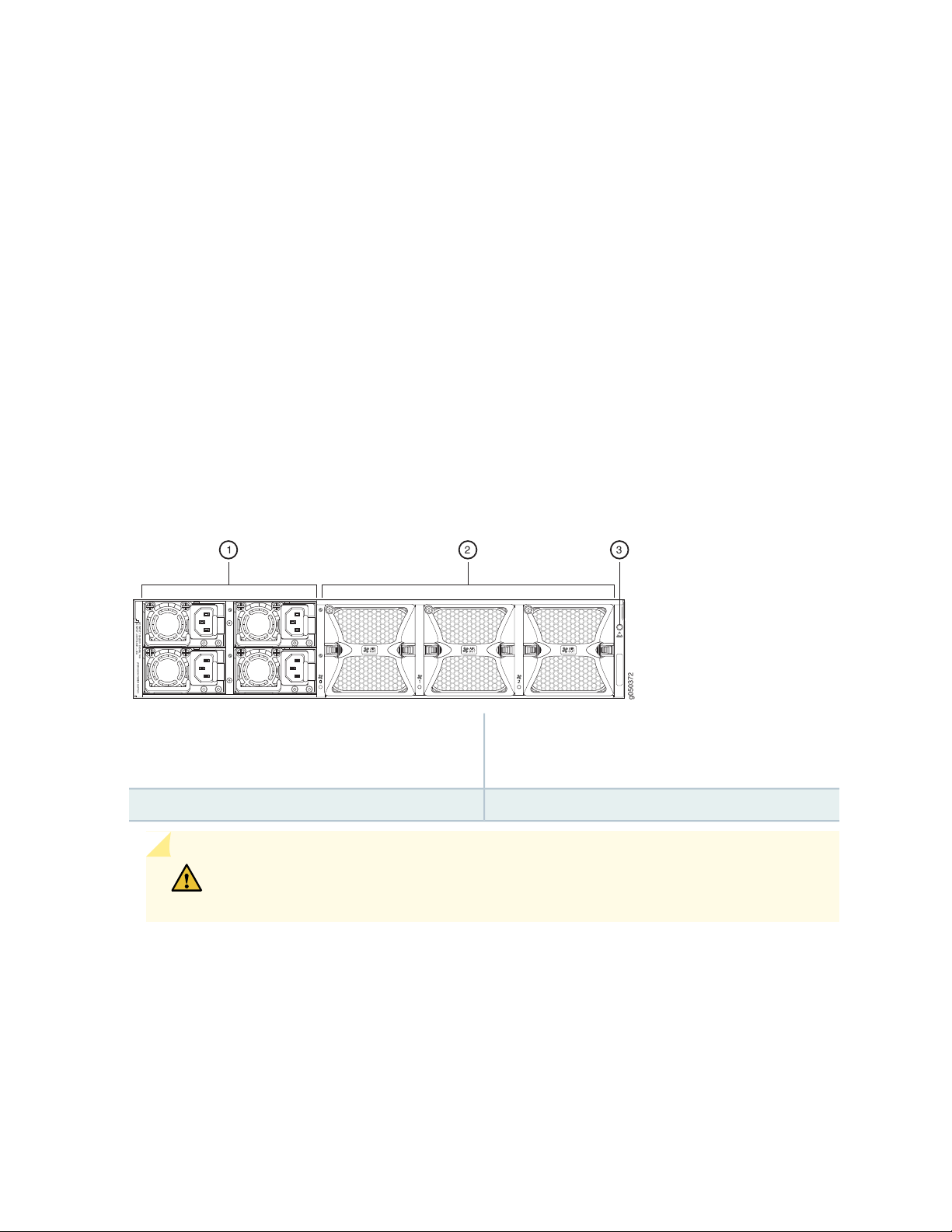
The four AC or DC 1600-W power supplies are installed by the factory in the QFX10002-72Q and
QFX10002-60C; two power supplies are installed in the QFX10002-36Q. See Figure 4 on page 22 for an
example of the QFX10002-72Q FRU panel. Each power supply provides 12 VDC output with a standby
voltage of 12-VDC.The AC or DC power supplies in a QFX10002 are hot-removable and hot-insertable
FRUs.
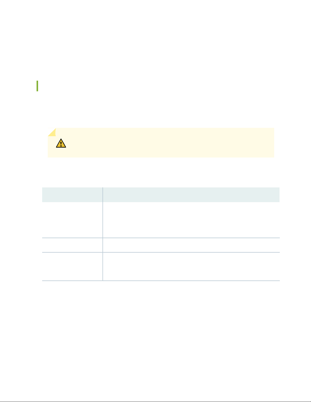
Figure 4: QFX10002 FRU Panel
22
3—1— ESD pointPower supply modules (4) for QFX10002-72Q and
QFX10002-60C. Two power supply modules are
provided for QFX10002-36Q.
2—Fan modules (3)
CAUTION: Mixing different types (AC and DC) of power supplies in the same chassis
is not supported.
The power supply bays on the QFX10002-72Q and QFX10002-36Q are numbered horizontally from the
top left to the bottom right. The QFX10002-60C power supply bays are numbered vertically from the top
left to the bottom right, which matches CLI output.
Page 23

System Software
QFX Series devices use the Junos operating system (OS), which provides Layer 2 and Layer 3 switching,
routing, and security services. Junos OS is installed on a QFX10002 switch’s 25-gigabyte (GB) internal
NAND solid state flash drive. The same Junos OS code base that runs on QFX10002 switches also runs
on all Juniper Networks EX Series switches, and M Series, MX Series, and T Series routers.
For more information about which features are supported on QFX Series devices, see Feature Tracker.
You manage the switch using the Junos OS command-line interface (CLI), which is accessible through the
console and out-of-band management ports on the device.
QFX10002 Hardware Component Overview
The QFX10002 supports the components in listed in alphabetic order. See “QFX10002 Chassis Physical
Specifications” on page 79 for the dimensions and weight of the QFX10002 models.
23
Table 5: QFX10002 Hardware Components
Chassis
Fan module
Power supplies
QFX10002-72Q-CHAS-S
JNP10002-60C
QFX10002-36Q-CHAS-S
QFX10002-FAN-S
JNP10002-FAN1
JPSU-1600W-AC-AFO
JPSU-1600W-DC-AFO
CLI OutputSpare Juniper Model NumberComponent
QFX10002-72Q
QFX10002-60C
QFX10002-36Q
QFX10002-xxx Fan Tray n, Front to Back Airflow - AFO
for QFX10002-72Q and QFX10002-36Q
QFX10002-60C Fan Tray, Front to Back Airflow - AFO
AC AFO 1600W PSU for QFX10002-72Q and
QFX10002-36Q
DC AFO 1600W PSU for QFX10002-72Q and
QFX10002-36Q
AC AFO 1600W PSU for QFX10002-60C
QFX10002 Component Redundancy
The following hardware components provide redundancy on QFX10002 models:
Page 24
Power supplies
•
As shown in Table 6 on page 24, the QFX10002-72Q and QFX10002-60C can operate with a single
DC input power supply or a single AC input power supply for 220VAC operation. A minimum of two AC
power supplies are required to operate the QFX10002-72Q and QFX10002-60C at 110VAC. The
QFX1002-36Q can operate with a single DC input power supply or it can operate with a single AC power
supply at 110VAC and 220VAC.
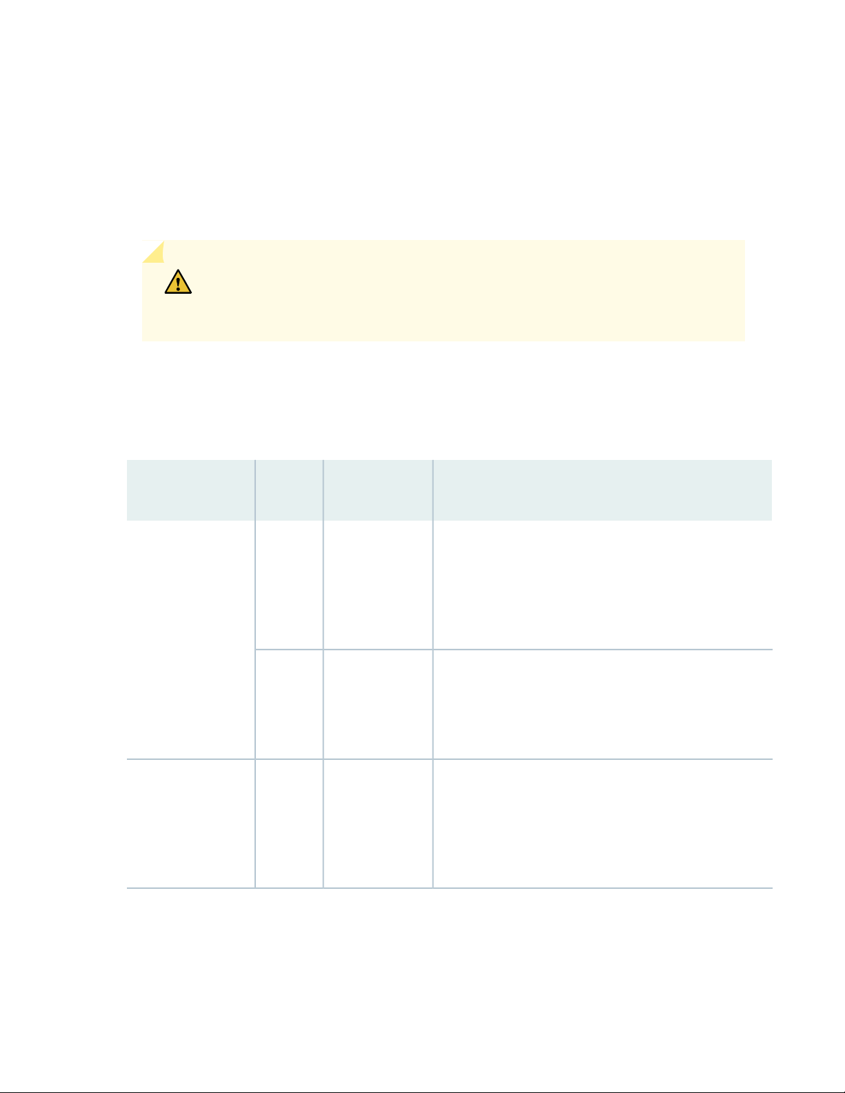
CAUTION: When running the switch in non-redundant mode, install a power supply
cover (QFX10002-PWR-BLNK) in any unused power bays for safety, cooling, and
emissions control.
The recommended configuration is to run the switch with twice as much power as needed, also called
2N, for full power redundancy. To provide additional power for switch redundancy or feed-redundancy,
see Table 6 on page 24.
Table 6: Available Power Redundancy Options
24
Non-redundant
(N)PowerModel
1220 VACQFX10002-72Q
2110 VAC
1DCQFX10002-72Q-DC
2N or Dual Feed
2
For power feed redundancy, connect power source feed A
to power supplies 0 or 1 and connect power source feed B
to power supplies 2 or 3. The remaining slots should be
covered with a power supply blank cover.
4
For power feed redundancy, connect power source feed A
to power supplies 0 and 1 and connect power source feed B
to power supplies 2 and 3.
2
For power feed redundancy, connect power source feed A
to power supplies 0 or 1 and connect power source feed B
to power supplies 2 or 3. The remaining slots should be
covered with a power supply blank cover.
Page 25

Table 6: Available Power Redundancy Options (continued)
Non-redundant
(N)PowerModel
2N or Dual Feed
25
1220 VACQFX10002-60C
2110 VAC
1DCQFX10002-60C-DC
1220 VACQFX10002-36Q
2
For power feed redundancy, connect power source feed A
to power supplies 0 or 1 and connect power source feed B
to power supplies 2 or 3. The remaining slots should be
covered with a power supply cover.
4
For power feed redundancy, connect power source feed A
to power supplies 0 and 1 and connect power source feed B
to power supplies 2 and 3.
2
For power feed redundancy, connect power source feed A
to power supplies 0 or 1 and connect power source feed B
to power supplies 2 or 3. The remaining slots should be
covered with a power supply blank cover.
2
For power feed redundancy, connect power source feed A
to power supplies 0 or 1 and connect power source feed B
to power supplies 2 or 3. The remaining slots should be
covered with a power supply cover.
1110 VAC
1DCQFX10002-36Q-DC
2
For power feed redundancy, connect power source feed A
to power supplies 0 or 1 and connect power source feed B
to power supplies 2 or 3. The remaining slots should be
covered with a power supply cover.
2
For power feed redundancy, connect power source feed A
to power supplies 0 or 1 and connect power source feed B
to power supplies 2 or 3. The remaining slots should be
covered with a power supply cover.
Page 26
Cooling system—All models of the QFX10002 have three fan modules. Each fan module is a redundant
•
unit containing two fans. If a fan module fails and is unable to keep the QFX10002 within the desired
temperature thresholds, chassis alarms occur and the QFX10002 device might shut down.
QFX10002 Field-Replaceable Units
Field-replaceable units (FRUs) are components that you can replace at your site. The QFX10002 FRUs are
hot-removable and hot-insertable: you can remove and replace them without powering off the switch or
disrupting the switching function.
CAUTION: Replace a failed fan module with a new fan module within one minute of
removal to prevent chassis overheating.
26
Table 7 on page 26 lists the FRUs for the QFX10002-72Q and actions to take before removing them.
Table 7: FRUs in a QFX10002 Device
Required ActionFRU
Remove the power cord for the power supply unit.Power supplies:
QFX10002-72Q and
QFX10002-60C (4),
QFX10002-36Q (2)
None.Fan modules (3)
Optical transceivers
None. We recommend that you disable the interface using the set interfaces
interface-name disable command before you remove the transceiver. See “Disconnect
a Fiber-Optic Cable” on page 140.
See Figure 5 on page 27 for an example of the FRU panel on a QFX10002-36Q.
Page 27
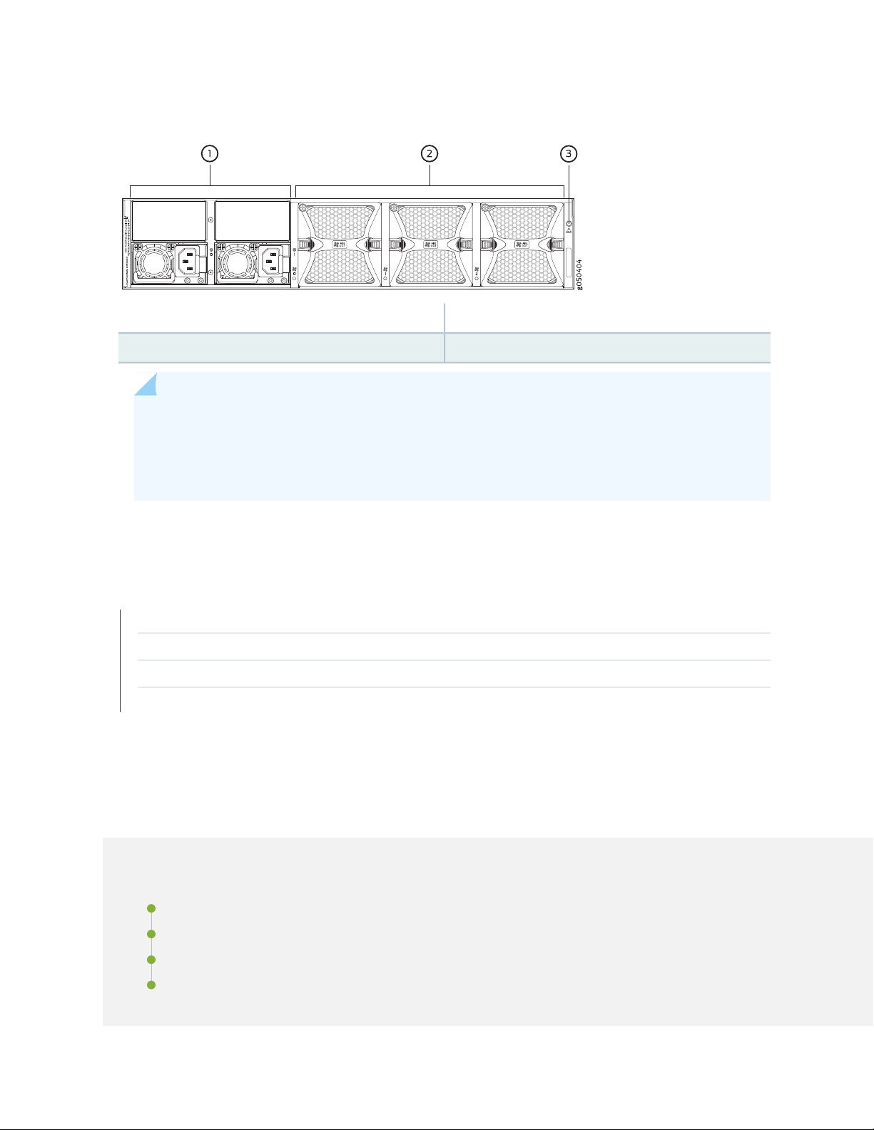
Figure 5: QFX10002-36Q FRU Panel
3—1— ESD pointPower supplies (2)
2—Fan modules (3)
NOTE: If you have a Juniper Care service contract, register any addition, change, or upgrade of
hardware components at https://www.juniper.net/customers/support/tools/updateinstallbase/
. Failure to do so can result in significant delays if you need replacement parts. This note does
not apply if you replace existing components with the same type of component.
27
RELATED DOCUMENTATION
QFX10002 Cooling System | 56
QFX10002 Power System | 60
QFX10002 Chassis Physical Specifications | 79
Installing and Removing QFX10002 Hardware Components | 125
QFX10002 Port Panels
IN THIS SECTION
QFX10002-36Q Port Panel | 28
QFX10002-60C Port Panel | 34
QFX10002-72Q Port Panel | 37
QFX10002 Network Port LEDs | 45
Page 28
QFX10002-36Q Port Panel
g050400
2
1
IN THIS SECTION
Overview | 28
Network Ports | 29
100-Gbps Operation and Configuration | 30
40-Gbps Channelization | 31
Port Mapping | 31
The port panel of the QFX10002-36Q consists of 36 quad small-form factor pluggable plus (QSFP+) ports
that support 10-Gbps, 40-Gbps and 100-Gbps port speeds. Of these 36 ports, 12 ports accept QSFP28
transceivers, which are dual speed 40- or 100-Gigabit Ethernet optical transceivers.
28
This topic describes:
Overview
Any of the 36 ports 0 through 35 can be configured as either uplink or network ports. See
Figure 6 on page 28.
Figure 6: QFX10002-36Q Port Panel
Management panel
2—1— Port panel with QSFP+ network interface or uplink
ports (36)
The default configuration is independent 40-Gigabit Ethernet for all 36 ports. For 100-Gbps or 10-Gbps
channelization operation, the ports operate within port groups. Every three ports compose a port group.
See Table 8 on page 29 and Figure 7 on page 30 through Figure 10 on page 31.
Page 29

Table 8: QFX10002-36Q Port Capacities
Per SwitchPer Port Group
12 x 100 Gbps1 x100 Gbps
36 x 40 Gbps3 x 40 Gbps
144 x 10 Gbps12 x 10 Gbps
The second and sixth port in each 6XQSFP+ socket can be configured to support:
100-Gigabit Ethernet using 28-Gbps QSFP28 optical transceivers and 100-Gbps active optical cables
•
(AOCs). When a QSFP28 transceiver is inserted into the ports marked with a fine black line underneath
the socket and the port is configured for 100-Gigabit Ethernet, the two adjacent ports are disabled and
the QSFP28 is enabled for 100-Gigabit Ethernet.
40-Gigabit Ethernet using QSFP+ optical transceivers or 40-Gbps direct attach copper (DAC) cables.
•
29
10-Gigabit Ethernet using DAC breakout cables (DACBO). When configured for channelization, a breakout
•
cable converts the 40-Gigabit Ethernet port into 4 independent 10-Gigabit Ethernet ports. The two
adjacent QSFP+ ports in the port group are also configured for channelization at the same time. You
cannot configure a single port for channelization.
Network Ports
Each of the 12 QSFP28 ports support:
100-Gigabit Ethernet QSFP28 transceivers
•
100-Gigabit Ethernet active optical cables (AOCs)
•
40-Gigabit Ethernet QSFP+ transceivers
•
40-Gigabit Ethernet QSFP+ DAC cables
•
40-Gigabit Ethernet QSFP+ to 10-Gigabit Ethernet SFP+ direct attach copper breakout (DACBO) cables
•
The remaining ports support:
40-Gigabit Ethernet QSFP+ transceivers
•
40-Gigabit Ethernet QSFP+ DAC cables
•
40-Gigabit Ethernet QSFP+ to 10-Gigabit Ethernet SFP+ DACBO cables
•
10-Gigabit Ethernet SFP+ transceivers
•
10-Gigabit Ethernet DAC cables
•
Page 30
100-Gbps Operation and Configuration
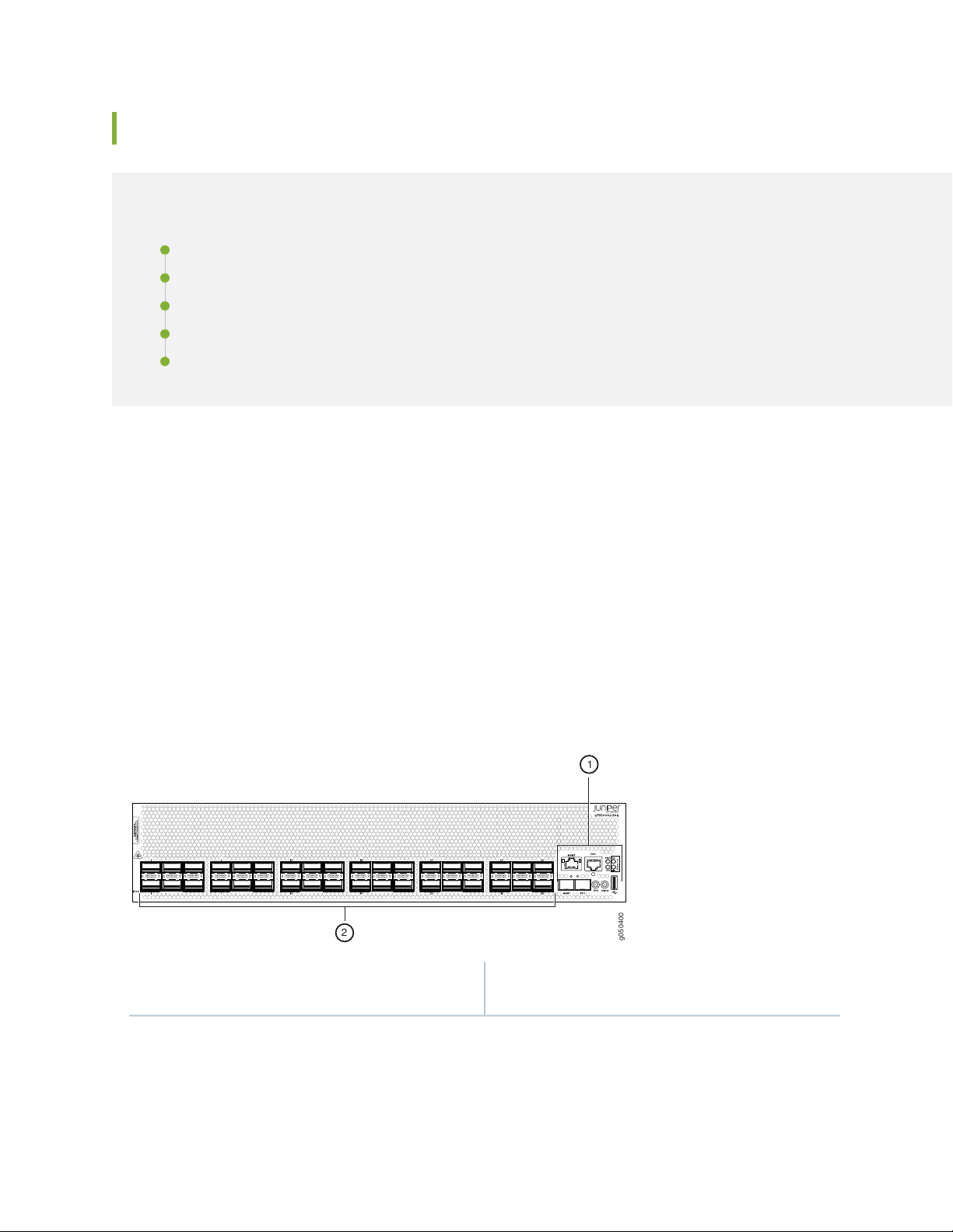
g0503 6 9
All por t s c an be u sed as 40-Gi gabit Ethern e t
g050 370
100-Gi g abit Ethern et por t s
Disab le d when 100-Gi gabit Ethern et
por t s are used
Every second and sixth port in a 6XQSFP cage on a QFX10002 supports 100-Gigabit Ethernet using
QSFP28 transceivers. These 100-Gigabit Ethernet ports work either as 100-Gigabit Ethernet or as
40-Gigabit Ethernet, but are recognized as 40-Gigabit Ethernet by default. See Figure 7 on page 30 for a
close up view of a 6XQSFP+ cage. The 100-Gigabit Ethernet are designated by a fine black line underneath
the port. See Figure 8 on page 30. When a 40-Gigabit Ethernet transceiver is inserted into a 100-Gigabit
Ethernet port, the port recognizes the 40-Gigabit Ethernet port speed. However, when an 100-Gigabit
Ethernet transceiver is inserted into the port, the transceiver is not automatically recognized and is not
seen in the output of the show chassis hardware command. To enable 100-Gigabit Ethernet on the marked
ports, use the set chassis fpc command. For example, to enable port 11 for 100 Gbps speeds:
[edit]
user@switch#
set chassis fpc 0 pic 0 port 11 speed 100g
30
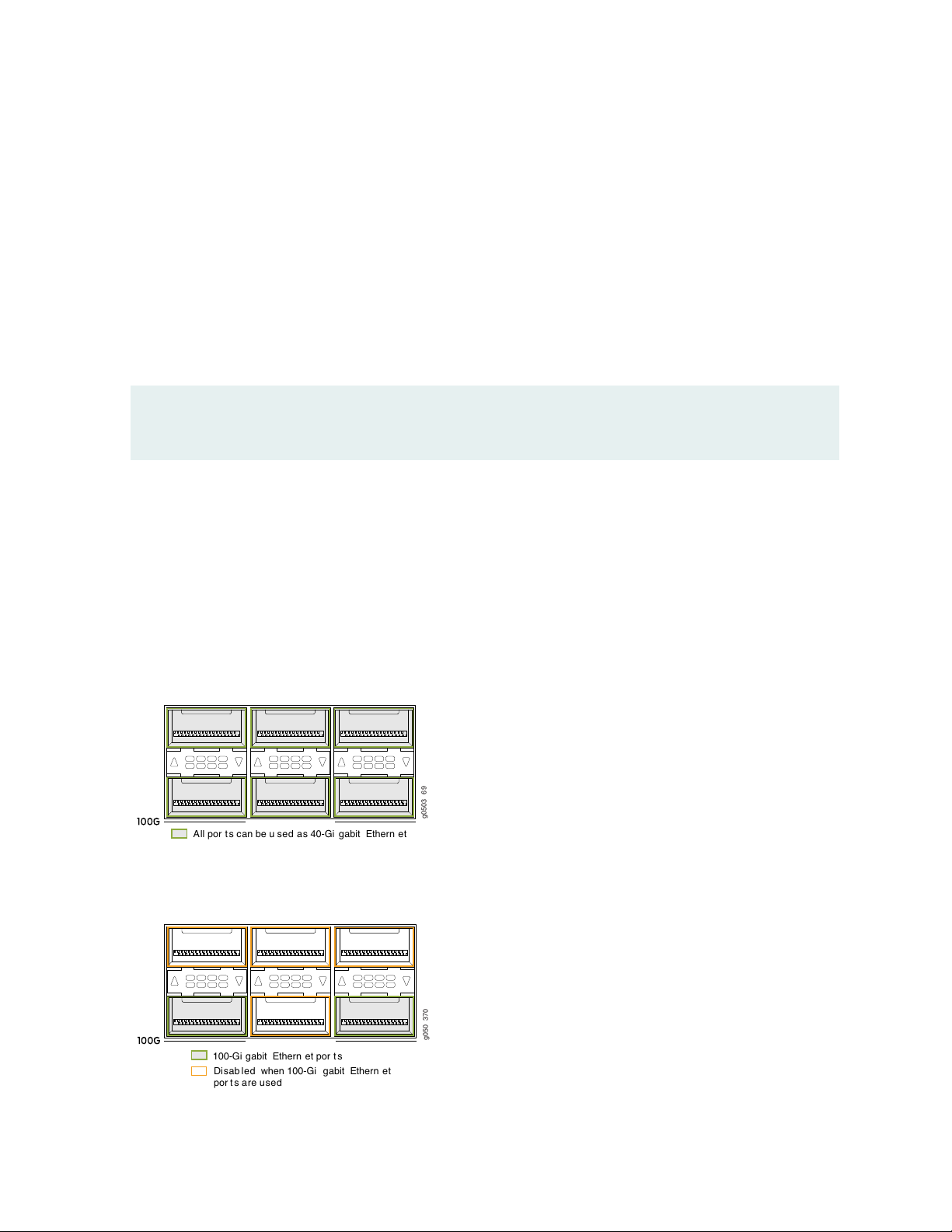
The port then recognizes the 100-Gigabit Ethernet speed and disables two adjacent 40-Gigabit Ethernet
ports. See Figure 9 on page 31.
Figure 7 on page 30 shows one of the six 6XQSFP+ cages on a QFX10002-36Q.
Figure 7: All Ports are 40-Gigabit Ethernet by Default
Figure 8: 100-Gigabit Ethernet Ports Are Indicated by a Black Line Underneath the Port
Page 31

Figure 9: 100-Gigabit Ethernet Port Disables Two Associated 40-Gigabit Ethernet Ports in the Port Group
g050 39 2
Port g rou ps
g050 420
Use every third port to create a port range for
40-Gigabit Channelization.
Port 0
Port 3
40-Gbps Channelization
The 40-Gigabit Ethernet ports can operate independently or be bundled with the next two consecutive
ports and channelized into twelve 10-Gigabit Ethernet ports as a port group. Like 100-Gigabit channelization,
only the first and fourth port in each 6XQSFP cage are available to channelize a port group (see
Figure 10 on page 31. The port group must be configured using the set chassis fpc pic port channel-speed
command. For example, to channelize the first switch port, use the set chassis fpc 0 pic 0 port 1
channel-speed 10g command.
31
NOTE: You cannot channelize an individual port. Channelizing configures all three ports in the
port range to four independent 10-Gigabit Ethernet.
Figure 10: Use the First and Fourth Port in Each 6XQSFP Cage to Channelize a Port Group
Port Mapping
Table 9 on page 32 shows the available combinations for the ports. Most 100-Gigabit Ethernet transceiver
ports are used as uplinks. On the QFX10002 device, the ports are enabled by default and the default config
adds the ports to the default VLAN.
Page 32

Table 9: QFX10002-36Q Port Mapping
4X10 Gigabit
4X10 Gigabit
EthernetPort Number
Channelized
Port Group
40 Gigabit
Ethernet
100 Gigabit
Ethernet
32
100 Gigabit Ethernet
Disables
––✓✓✓0
0, 2✓✓✓1
––✓✓2
––✓✓✓3
––✓✓4
3, 4✓✓✓5
––✓✓✓6
6, 8✓✓✓7
––✓✓8
––✓✓✓9
––✓✓10
9, 10✓✓✓11
––✓✓✓12
12, 14✓✓✓13
––✓✓14
––✓✓✓15
––✓✓16
15, 16✓✓✓17
Page 33

Table 9: QFX10002-36Q Port Mapping (continued)
4X10 Gigabit
4X10 Gigabit
EthernetPort Number
Channelized
Port Group
40 Gigabit
Ethernet
100 Gigabit
Ethernet
33
100 Gigabit Ethernet
Disables
––✓✓✓18
18, 20✓✓✓19
––✓✓20
––✓✓✓21
––✓✓22
21, 22✓✓✓23
––✓✓✓24
24, 26✓✓✓25
––✓✓26
––✓✓✓27
––✓✓28
27, 28✓✓✓29
––✓✓✓30
30, 32✓✓✓31
––✓✓32
––✓✓✓33
––✓✓34
33, 34✓✓✓35
Page 34

QFX10002-60C Port Panel
g050765
MGMT
MGMT
PTP CON
5549
48
19
54
25
24181260
1
30
31
6
36
37
13
42
43
1
1
2
IN THIS SECTION
Overview | 34
Network Ports | 35
Channelization | 35
The port panel of the QFX10002-60C consists of 60 high-density 100-Gigabit Ethernet quad small
form-factor pluggable solution (QSFP28) ports and the management panel. The highly-flexible ports support
10-Gbps, 40-Gbps and 100-Gbps port speeds. See Figure 11 on page 34.
Figure 11: QFX10002-60C Port Panel
34
2—1— Management panelPort panel with QSFP28 access interface or uplink
ports (60)
This topic describes:
Overview
The QFX10002-60C ports support the flexible configuration of 100-Gbps, 40-Gbps, and 10-Gbps. Each
port auto-senses a 100-Gbps QSFP28 or 40-Gbps QSFP transceiver and sets the speed accordingly. Any
of the 60 ports, 0 through 59, can be configured as either uplink or access ports. See Table 10 on page 34.
Table 10: QFX10002-60 Port Capacities
ChannelizationPer SwitchPer Port
Non-channelized60 x 100 Gbps1 x100 Gbps
Page 35

Table 10: QFX10002-60 Port Capacities (continued)
ChannelizationPer SwitchPer Port
Non-channelized60 x 40 Gbps1 x 40 Gbps
192 x 10 Gbps4 x 10 Gbps
Network Ports
The QFX10002-60C supports the following types of optics and cables:
100-Gigabit Ethernet using 28-Gbps QSFP28 optical transceivers and 100-Gbps active optical cables
•
(AOCs).
40-Gigabit Ethernet using QSFP+ optical transceivers, 40-Gbps AOCs, or 40-Gbps direct attach copper
•
(DAC) cables.
10-Gigabit Ethernet using DAC breakout cables (DACBO). When configured for channelization, a breakout
•
cable converts the 40-Gigabit Ethernet port into 4 independent 10-Gigabit Ethernet ports.
35
For a detailed list of supported optical transceivers and electrical cables, see The Hardware Compatibility
Tool.
Channelization
Although he QFX10002-60C autosenses the speed of a transceiver and sets the speed to either 40 Gbps
or 100 Gbps, for channelization you must manually configure the port speed. Any of the 60 physical ports
that are configured for 40 Gbps speeds can be channelized to 4 independent 10-Gigabit Ethernet interfaces
using copper or fiber breakout cables. You can channelize an individual port or a create a port range.
Port behavior is tied to the ASIC associated with the port. You must configure each port individually, in
order to channelize a 40-Gigabit Ethernet port to 4 independent 10-Gigabit Ethernet ports. The first time
a port for an associated ASIC is changed from the default configuration mode (mode D) to the channelization
mode (mode A), the FPC reboots. Subsequent channelization of the ports for that ASIC does not cause
the FPC to reboot. However if one of the channelized ports is changed back to the default, the FPC will
again reboot. See Table 11 on page 36 for the list of available ports and the associated ASIC.
NOTE: Beginning in Junos OS 18.3R1, when the default configuration mode changes to the
channelization mode, only the associated ASIC reboots.
The switch, as a whole, does not have port groups; however, within the ASIC, there are four port groups
shared by the five physical ports. When one of the ports in the port group is channelized, the fifth port is
Page 36

disabled and cannot be channelized. If ports in all 12 ASICs are channelized, the switch has a maximum of
192 10-Gigabit Ethernet interfaces.
CAUTION: Changing the channelization mode (mode D to mode A or mode A to mode
D) causes the FPC to reboot. Because there can be a slight loss of data while the FPC
reboots, we recommend that you only configure the changes during a maintenance
window.
Table 11: Port Mapping for Channelization
Physical Ports that Become
DisabledPhysical Ports Available for ChannelizationASIC
3630,32,34,38PE0
3731,33,35,39PE1
36
4640,42,44,48PE2
4741,43,45,49PE3
5650,52,54,58PE4
5751,53,55,59PE5
60,2,4,8PE6
71,3,5,9PE7
1610,12,14,18PE8
1711,13,15,19PE9
2620,22,24,28PE10
2721,23,25,29PE11
To change from the default mode to 40-Gigabit Ethernet channelized mode, use the Junos OS operational
command set chassis fpc slot-number pic 0 port port number speed 10g.
Page 37

QFX10002-72Q Port Panel
g050366
1
1
2
IN THIS SECTION
Overview | 37
Switch Ports | 38
100-Gbps Operation and Configuration | 39
40-Gbps Channelization | 40
Port Mapping | 40
The port panel of the QFX10002-72Q consists of 72 quad small-form factor pluggable plus (QSFP+) ports
that support 10-Gbps, 40-Gbps and 100-Gbps port speeds. Of these 72 ports, 24 ports accept QSFP28
transceivers, which are dual speed 40- or 100-Gigabit Ethernet optical transceivers.
37
This topic describes:
Overview
Any of the 72 ports 0 through 71 can be configured as either uplink or access ports. See
Figure 12 on page 37.
Figure 12: QFX10002-72Q Port Panel
2—1— Management panelPort panel with QSFP+ access interface or uplink
ports (72)
The default configuration is independent 40-Gigabit Ethernet for all 72 ports. For 100-Gbps or 10-Gbps
channelization operation, the ports operate within port groups. Every 3 ports compose a port group. See
Table 12 on page 38 and Figure 13 on page 39 through Figure 16 on page 40.
Page 38

Table 12: QFX10002-72Q Port Capacities
Per SwitchPer Port Group
24 x 100 Gbps1 x100 Gbps
72 x 40 Gbps3 x 40 Gbps
288 x 10 Gbps12 x 10 Gbps
The second and sixth port in each 6XQSFP+ socket can be configured to support:
100-Gigabit Ethernet using 28-Gbps QSFP28 optical transceivers and 100-Gbps active optical cables
•
(AOCs). When a QSFP28 transceiver is inserted into the ports marked with a fine black line underneath
the socket and the port is configured for 100-Gigabit Ethernet, the two adjacent ports are disabled and
the QSFP28 is enabled for 100-Gigabit Ethernet.
40-Gigabit Ethernet using QSFP+ optical transceivers or 40-Gbps direct attach copper (DAC) cables.
•
38
10-Gigabit Ethernet using DAC breakout cables (DACBO). When configured for channelization, a breakout
•
cable converts the 40-Gigabit Ethernet port into 4 independent 10-Gigabit Ethernet ports.The two
adjacent QSFP+ ports in the port group are also configured for channelization at the same time. You
cannot configure a single port for channelization.
Switch Ports
Each of the 24 QSFP28 ports support:
100-Gigabit Ethernet QSFP28 transceivers
•
100-Gigabit Ethernet active optical cables (AOCs)
•
40-Gigabit Ethernet QSFP+ transceivers
•
40-Gigabit Ethernet QSFP+ DAC cables
•
40-Gigabit Ethernet QSFP+ to 10-Gigabit Ethernet SFP+ direct attach copper breakout (DACBO) cables
•
The remaining ports support:
40-Gigabit Ethernet QSFP+ transceivers
•
40-Gigabit Ethernet QSFP+ DAC cables
•
40-Gigabit Ethernet QSFP+ to 10-Gigabit Ethernet SFP+ DACBO cables
•
10-Gigabit Ethernet SFP+ transceivers
•
10-Gigabit Ethernet DAC cables
•
Page 39

100-Gbps Operation and Configuration
g0503 6 9
All por t s c an be u sed as 40-Gi gabit Ethern e t
g050 370
100-Gi g abit Ethern et por t s
Disab le d when 100-Gi gabit Ethern et
por t s are used
Every second and sixth port in a 6XQSFP cage on a QFX10002 supports 100-Gigabit Ethernet using
QSFP28 transceivers. These 100-Gigabit Ethernet ports work either as 100-Gigabit Ethernet or as
40-Gigabit Ethernet, but are recognized as 40-Gigabit Ethernet by default. See Figure 13 on page 39 for
a close up view of a 6XQSFP+ cage. The 100-Gigabit Ethernet are designated by a fine black line underneath
the port. See Figure 14 on page 39. When a 40-Gigabit Ethernet transceiver is inserted into a 100-Gigabit
Ethernet port, the port recognizes the 40-Gigabit Ethernet port speed. However, when an 100-Gigabit
Ethernet transceiver is inserted into the port, the transceiver is not automatically recognized and is not
seen in the output of the show chassis hardware command. To enable 100-Gigabit Ethernet on the marked
ports, use the set chassis fpc command. For example, to enable port 71 for 100 Gbps speeds:
[edit]
user@switch#
set chassis fpc 0 pic 0 port 71 speed 100g
39
The port then recognizes the 100-Gigabit Ethernet speed and disables two adjacent 40-Gigabit Ethernet
ports. See Figure 15 on page 40.
Figure 13 on page 39 shows the location of QSFP+ ports for the QFX10002-72Q.
Figure 13: All Ports are 40-Gigabit Ethernet by Default
Figure 14: 100-Gigabit Ethernet Ports Are Indicated by a Black Line Underneath the Port
Page 40

Figure 15: 100-Gigabit Ethernet Port Disables Two Associated 40-Gigabit Ethernet Ports in the Port
g050 39 2
Port g rou ps
g050 420
Use every third port to create a port range for
40-Gigabit Channelization.
Port 0
Port 3
Group
40-Gbps Channelization
The 40-Gigabit Ethernet ports can operate independently or bundled with the next two consecutive ports
and channelized into twelve 10-Gigabit Ethernet ports as a port group. Like 100-Gigabit channelization,
only the first and fourth port in each 6XQSFP cage are available to channelize a port group (see
Figure 16 on page 40). The port group must be configured using the set chassis fpc pic port channel-speed
command. For example, to channelize the first switch port, use the set chassis fpc 0 pic 0 port 1
channel-speed 10g command.
40
Figure 16: Use the First and Fourth Port in Each 6XQSFP Cage to Channelize a Port Group
Port Mapping
Table 13 on page 41 shows the available combinations for the ports. Most 100-Gigabit Ethernet transceiver
ports are used as uplinks . On the QFX10002, the ports are enabled by default and the default configuration
adds the ports to the default VLAN.
Page 41

Table 13: QFX10002-72Q Port Mapping
41
4X10 Gigabit
Ethernet
PortPort Number
4X10 Gigabit
Channelized
Port Group
40 Gigabit
Ethernet
(Default)
100 Gigabit
Ethernet
100 Gigabit Ethernet
Disables
––✓✓✓0
0, 2✓✓✓1
––✓✓2
––✓✓✓3
––✓✓4
3, 4✓✓✓5
––✓✓✓6
6, 8✓✓✓7
––✓✓8
––✓✓✓9
––✓✓10
9, 10✓✓✓11
––✓✓✓12
12, 14✓✓✓13
––✓✓14
––✓✓✓15
––✓✓16
15, 16✓✓✓17
Page 42

Table 13: QFX10002-72Q Port Mapping (continued)
42
4X10 Gigabit
Ethernet
PortPort Number
4X10 Gigabit
Channelized
Port Group
40 Gigabit
Ethernet
(Default)
100 Gigabit
Ethernet
100 Gigabit Ethernet
Disables
––✓✓✓18
18, 20✓✓✓19
––✓✓20
––✓✓✓21
––✓✓22
21, 22✓✓✓23
––✓✓✓24
24, 26✓✓✓25
––✓✓26
––✓✓✓27
––✓✓28
27, 28✓✓✓29
––✓✓✓30
30, 32✓✓✓31
––✓✓32
––✓✓✓33
––✓✓34
33, 34✓✓✓35
Page 43

Table 13: QFX10002-72Q Port Mapping (continued)
43
4X10 Gigabit
Ethernet
PortPort Number
4X10 Gigabit
Channelized
Port Group
40 Gigabit
Ethernet
(Default)
100 Gigabit
Ethernet
100 Gigabit Ethernet
Disables
––✓✓✓36
36, 38✓✓✓37
––✓✓38
––✓✓✓39
––✓✓40
39, 40✓✓✓41
––✓✓✓42
42, 44✓✓✓43
––✓✓44
––✓✓✓45
––✓✓46
45, 46✓✓✓47
––✓✓✓48
48, 50✓✓✓49
––✓✓50
––✓✓✓51
––✓✓52
51, 52✓✓✓53
Page 44

Table 13: QFX10002-72Q Port Mapping (continued)
44
4X10 Gigabit
Ethernet
PortPort Number
4X10 Gigabit
Channelized
Port Group
40 Gigabit
Ethernet
(Default)
100 Gigabit
Ethernet
100 Gigabit Ethernet
Disables
––✓✓✓54
54, 56✓✓✓55
––✓✓56
––✓✓✓57
––✓✓58
57, 58✓✓✓59
––✓✓✓60
60, 62✓✓✓61
––✓✓62
––✓✓✓63
––✓✓64
63, 64✓✓✓65
––✓✓✓66
66, 68✓✓✓67
––✓✓68
––✓✓✓69
––✓✓70
69, 70✓✓✓71
Page 45

QFX10002 Network Port LEDs
g0503 6 9
All por t s c an be u sed as 40-Gi gabit Ethern e t
Each QFX10002 QSFP+ port uses a single bi-colored LED to indicate link status and activity. See
Figure 17 on page 45 for an example of these triangle shaped LEDs.
Figure 17: Port LEDs
The same single bi-colored LED also indicates when the interface is configured and connected using an
optical split cable or a copper DACBO cable to a 10-Gigabit Ethernet port.
45
There are some slight differences in the amber LED behavior depending on the firmware level of the
complex programmable logic device (CPLD) in your switch and the Junos release level running on the
switch. To determine the Junos release level, use the show version command. To determine the CPLD of
your switch, use the show chassis firmware command. For example:
root@> show chassis firmware
Part Type Version
FPC 0 U-Boot ***
loader FreeBSD/i386 bootstrap loader 1.2
BIOS V0018.2U
EC FPGA 2.3
MAIN_CPLD 1.10
MEZZ_CPLD 1.10
RE FPGA 2.4
root@>
See Table 14 on page 45 for how to interpret the QSFP+ LEDs.
Table 14: Network Port LEDs on QSFP+ Ports on a QFX10002
DescriptionStateColor
OffUnlit
The port is administratively disabled, there is no power, the
link is down, or a transceiver is not present. All sub-channels
are disabled.
Page 46

Table 14: Network Port LEDs on QSFP+ Ports on a QFX10002 (continued)
DescriptionStateColor
46
On steadilyGreen
1750 ms off)
Blinking (500 ms on and
500 ms off)
On steadilyAmber
A link is established. When channelized, all sub-channels are
up. When not channelized, it indicates no activity.
The beacon function was enabled on the port.Slow blinking (250 ms on and
When channelized, all four channels are up and active. When
not channelized, it indicates the port is up and active in either
40-Gigabit or 100-Gigabit mode.
For Junos Release 15.1X53-D21 or later and CPLD
version V1.16 or later:
One or more breakout connections (sub-channels) are up.
However not all sub-channels are up and there is no port
activity.
For Junos Release 15.1X53-D10 to 15.1X53-D20 and
CPLD version V1.10:
Solid yellow LED is not available.
Blinking
One or more breakout connections (sub-channels) are up. At
least one sub-channel has activity, but not all connections are
active.
RELATED DOCUMENTATION
QFX10002 Field-Replaceable Units | 26
Channelizing Interfaces on QFX3500, QFX3600, QFX5100, QFX10002, QFX10008, QFX10016, and
EX4600 Switches
Installing and Removing QFX10002 Hardware Components | 125
Page 47

QFX10002 Management Panel
g050366
1
1
2
IN THIS SECTION
QFX10002 Management Panel | 47
QFX10002 Management Port LEDs | 50
QFX10002 Chassis Status LEDs | 52
QFX10002 Management Panel
The QFX10002 management panel is found next to the ports as shown in Figure 18 on page 47 through
Figure 20 on page 48. See Figure 21 on page 49 and Figure 22 on page 50 for management panel detail.
47
Figure 18: QFX10002-72Q Port Panel and Management Panel
2—1— Management panelPort panel
Page 48

Figure 19: QFX10002-36Q Port Panel and Management Panel
g050400
2
1
g050765
MGMT
MGMT
PTP CON
5549
48
19
54
25
24181260
1
30
31
6
36
37
13
42
43
1
1
2
48
Management panel
2—1— Port panel with QSFP+ network interface or uplink
ports (36)
Figure 20: QFX10002-60C Port Panel and Management Panel
2—1— Management panelPort panel
Page 49

Figure 21: QFX10002 72Q and QFX20002-36Q Management Panel Components
6—1— PTP Ethernet–SFP (1000BASE-T) port (ETH)em0–RJ-45 (1000BASE-T) management Ethernet
port (MGMT).
49
RJ-45 console port (CON) to support RS-232 serial
ports. The LED below the port indicates status and
link.
hardware. Clock functions and FPGA status registers
are not reset.
(MJR), and minor alarm (MIN).
5—em1–SFP management Ethernet port (MGMT).
7—2— 10 Hz pulses-per-second (PPS) SubMiniature B (SMB)
connector for input and output measuring of the
timing drift to and from a grandmaster clock
8—3— 10 MHz SMB timing connector (10MHz)Reset button. Press and hold 5 seconds to reset the
9—4— USB portStatus LEDs–Power (PWR), status (STA), major alarm
Page 50

Figure 22: QFX10002 60C Management Panel Components
g051219
1
2
3
4
6 5
8
7
5—1— 10 MHz SMB timing connector (10MHz)USB port
50
Status LEDs–Power (PWR), status (STA), major alarm
(MJR), and minor alarm (MIN).
6—2— 10 Hz pulses-per-second (PPS) SubMiniature B (SMB)
connector for input and output measuring of the
timing drift to and from a grandmaster clock
7—3— PTP Ethernet–SFP (1000BASE-T) port (ETH)em0–RJ-45 (1000BASE-T) management Ethernet
port (MGMT).
8—4— em1–SFP management Ethernet port (MGMT).RJ-45 console port (CON) to support RS-232 serial
ports.
SEE ALSO
USB Port Specifications for the QFX Series | 98
Connecting a QFX10002 to a Management Ethernet Device | 112
QFX10002 Management Port LEDs
There are two managements ports on a QFX10002 that have LEDs that indicate link status and link activity.
These two ports, located on the management panel next to the access ports, are both labeled MGMT. The
top management port is for 10/100/1000 BASE-T connections and the lower port is for 10/100/1000
BASE-T and small-form pluggable (SFP) 1000 BASE-X connections (see Figure 23 on page 51). The copper,
RJ45, port has separate LEDs for status and activity. The fiber, SFP, port has a combination link and activity
LED.
Page 51

Figure 23: Management Port LEDs on a QFX10002 Switch
g050398
1
2
3
51
Status LED (RJ45)
3—1— Green indicates the link is up; blinking indicates
activity (SFP)
2—Activity LED (RJ45)
Table 15 on page 51 and Table 16 on page 51 describes the management port LEDs.
Table 15: RJ-45 Management Port LEDs on a QFX10002 Switch
DescriptionStateColorLED
OffUnlitLink/Activity
No link is established, there is a fault, or the link is
down.
A link is established, and there is link activity.Blinking or flickeringYellow
Either the port speed is 10 M or the link is down.OffUnlitStatus
The port speed is 1000 M.On steadilyGreen
Table 16: SFP Management Port LEDs on a QFX10002 Switch
DescriptionStateColorLED
No link is established or the link is down.OffUnlitLink/Activity
Link is up and there is no activity.On steadilyGreen
A link is established, and there is link activity.BlinkingGreen
Page 52

QFX10002 Chassis Status LEDs
g050368
1
4
2
3
The QFX10002 has four status LEDs on the port side of the chassis, next to the access ports (see
Figure 24 on page 52).
Figure 24: Chassis Status LEDs on QFX10002 Models
52
3—1— MINPWR
4—2— STAMJR
Table 17 on page 52 describes the chassis status LEDs on a QFX10002, their colors and states, and the
status they indicate.
Table 17: Chassis Status LEDs on a QFX10002 Switch
DescriptionStateColorName
OffUnlitPWR–Alarm
BlinkingYellow
The switch is powered off; no power
to the device.
Power is working correctly.On steadilyGreen
There is a problem with chassis power.
Power off the QFX10002 by setting
the AC power source outlet to the OFF
(O) position, or unplugging the AC
power cords. Correct any voltage
issues. Power on the QFX10002 and
monitor the power supply and fan
LEDs to help determine where the
error is occurring. If there is any CPU
power failure, the system will not boot.
Page 53

Table 17: Chassis Status LEDs on a QFX10002 Switch (continued)
53
DescriptionStateColorName
The switch is powered off or halted.OffUnlitSTA–Status
On steadilyGreen
BlinkingGreen
On steadilyRed
On steadilyYellow
Junos OS for QFX Series is loaded on
the switch.
The beacon feature is enabled on the
switch. This feature is enabled using
the request chassis beacon command.
The switch detects a fault.BlinkingYellow
There are no major alarms.OffUnlitMJR–Major alarm
A major hardware fault has occurred,
such as a temperature alarm or power
failure, and the switch has halted.
There are no minor alarms.OffUnlitMIN–Minor alarm
A minor alarm has occurred, such as a
software error.
For power and temperature alarms, you can use the show chassis environment fpc operational mode
command to get detailed information on the internal state of the chassis. For example:
user@device> show chassis environment fpc
FPC 0 status:
State Online
Temperature 51 degrees C / 123 degrees F
Voltage:
PE0 VDD Core 0.9V 949 mV
PE0 AVDD 1.0V 1000 mV
PE0 HMC VDD 0.9V 897 mV
PE0 HMC AVDD 1.2V 1197 mV
PE01 HMC VDD 1.2V 1197 mV
PE1 VDD Core 0.9V 949 mV
PE1 AVDD Core 1.0V 999 mV
PE1 HMC VDD 0.9V 899 mV
Page 54

PE1 HMC AVDD 1.2V 1197 mV
PE2 VDD Core 0.9V 950 mV
PE2 AVDD Core 1.0V 999 mV
PE2 HMC VDD 0.9V 897 mV
PE2 HMC AVDD 1.2V 1197 mV
PE23 HMC AVDD 1.2V 1197 mV
PE3 VDD Core 0.9V 949 mV
PE3 AVDD Core 1.0V 999 mV
PE3 HMC VDD 0.9V 899 mV
PE3 HMC AVDD 1.2V 1200 mV
PE4 VDD Core 0.9V 949 mV
PE4 AVDD Core 1.0V 999 mV
PE4 HMC VDD 0.9V 899 mV
PE4 HMC AVDD 1.2V 1197 mV
PE45 HMC AVDD 1.2V 1197 mV
PE5 VDD Core 0.9V 949 mV
PE5 AVDD Core 1.0V 1000 mV
PE5 HMC VDD 0.9V 899 mV
PE5 HMC AVDD 1.2V 1200 mV
XMB VDD 3.3V 3316 mV
MAIN VDD 3.3V 3298 mV
RT VDD 1.0V 999 mV
MAIN VDD 2.5V 2502 mV
MAIN PFE 1.5V 1502 mV
PE6 VDD Core 0.9V 949 mV
PE6 AVDD 1.0V 1000 mV
PE6 HMC VDD 0.9V 897 mV
PE6 HMC AVDD 1.2V 1204 mV
PE67 HMC VDD 1.2V 1197 mV
PE7 VDD Core 0.9V 949 mV
PE7 AVDD Core 1.0V 999 mV
PE7 HMC VDD 0.9V 897 mV
PE7 HMC AVDD 1.2V 1197 mV
PE8 VDD Core 0.9V 949 mV
PE8 AVDD Core 1.0V 999 mV
PE8 HMC VDD 0.9V 897 mV
PE8 HMC AVDD 1.2V 1200 mV
PE78 HMC AVDD 1.2V 1197 mV
PE9 VDD Core 0.9V 950 mV
PE9 AVDD Core 1.0V 999 mV
PE9 HMC VDD 0.9V 897 mV
PE9 HMC AVDD 1.2V 1200 mV
PE10 VDD Core 0.9V 949 mV
PE10 AVDD Core 1.0V 999 mV
54
Page 55

PE10 HMC VDD 0.9V 899 mV
PE10 HMC AVDD 1.2V 1200 mV
PE910 HMC AVDD 1.2V 1200 mV
PE11 VDD Core 0.9V 950 mV
PE11 AVDD Core 1.0V 999 mV
PE11 HMC VDD 0.9V 899 mV
PE11 HMC AVDD 1.2V 1200 mV
PF0 VDD Core 0.9V 950 mV
PF0 AVDD Core 1.0V 999 mV
PF1 VDD Core 0.9V 950 mV
PF1 AVDD Core 1.0V 999 mV
XDB VDD 3.3V 3298 mV
XDB RT VDD 1.0V 999 mV
MEZZ VDD 2.5V 2502 mV
MEZZ PFE 1.5V 1502 mV
MEZZ GEX 1.0V 999 mV
VCC 1.0V 1009 mV
VCC 0.85V 862 mV
VDD RAIL 12.0V 0 mV
VCC 1.8V 1793 mV
VDD 1.2V 1215 mV
PCH VCC 1.0V 999 mV
CPU VCC 1.8V 1803 mV
BIAS 1 3.3V 3312 mV
AUX VCC 5.0V 4165 mV
DDR VDD 1.5V 1499 mV
VTT SA CPU 0.8V 803 mV
VTT CPU 1.05V 1048 mV
CORE CPU 1.0V 940 mV
PCH VCC 1.5V 1509 mV
PCH VCC 1.05V 1058 mV
VDD 2.5V 2508 mV
55
SEE ALSO
show chassis alarms
request chassis beacon
RELATED DOCUMENTATION
Page 56

Connecting a QFX10002 to a Management Ethernet Device | 112
QFX10002 Cooling System
IN THIS SECTION
QFX10002 Cooling System and Airflow | 56
QFX10002 Fan Module LED | 59
QFX10002 Cooling System and Airflow
56
IN THIS SECTION
Fan Modules | 56
Fan Module Status | 58
The cooling system in a QFX10002 consists of three 80-W fan modules in a fan tray and two
counter-rotating fans housed in each of the power supplies.
The QFX10002 brings air into the vents in the port panel and exhausts warmed air through the
field-replaceable units (FRU) panel. This type of airflow is known as airflow out or port-to-FRU airflow.
This topic describes:
Fan Modules
The fan modules in a QFX10002 are hot-removable and hot-insertable FRUs designed for port-to-FRU
airflow. The fan modules numbered 0 through 2 are installed in the fan tray located next to the power
supplies. Each fan module slot has a fan icon next to it.
Figure 25 on page 57 shows the 2-U fan module for the QFX10002 models.
Page 57

Figure 25: Fan Module for the QFX10002
g050375
You remove and replace a fan module from the FRU end of the chassis. The switch continues to operate
for a limited period of time (30 seconds) during the replacement of the fan module without thermal
shutdown.
NOTE: All fan modules must be installed for optimal operation of the switch.
57
Table 18 on page 57 lists the fan module details.
Table 18: Fan Modules in the QFX10002
Direction of
Airflow in
the Fan
Module
Port-to-FRU
airflow is
where air
enters on the
end with the
ports and exits
on the end
with fans (also
known as
airflow out).
Power Supplies
All models only
use power
supplies that
have
gold-colored
handles with AIR
OUT labels.
Airflow
DiagramFan Module
Label on
the Fan
Module
AIR OUTFigure26on page 58QFX10002-FAN
Color of
Fan
Module
Handle
Juniper
Gold
In data center deployments, position the switch in such a manner that the AIR OUT labels on switch
components are next to the hot aisle. Figure 26 on page 58 shows the airflow through the chassis.
Page 58

Figure 26: Air Out Airflow Through the QFX10002 Chassis
g050 376
FRUs Por t s
Fan Module Status
You can check the status of fan modules through the show system alarms command or show chassis fan
commands or by looking at the LEDs next to each fan module. For example:
58
user@device> show chassis fan
Item Status RPM Measurement
Tray 0 Fan 0 Absent
Tray 0 Fan 1 Absent
Tray 1 Fan 0 OK 5000 Spinning at normal speed
Tray 1 Fan 1 OK 4400 Spinning at normal speed
Tray 2 Fan 0 OK 5000 Spinning at normal speed
Tray 2 Fan 1 OK 4400 Spinning at normal speed
Each switch has a status LED (labeled ST) for each fan module on the left side of the corresponding fan
module slot. It indicates the status of all the fan modules. Table 19 on page 58 describes the status LED
on the fan module in a QFX10002.
Table 19: Fan Module Status LED
DescriptionLED State
Solid Green
Indicates the individual fan module is present. After the hardware senses the fan module,
software ensures the airflow is consistent with the other fan modules and that it is
functioning correctly.
Page 59

Table 19: Fan Module Status LED (continued)
DescriptionLED State
59
Solid Amber
Indicates one of the following:
The fan module is not present.
•
The fan module is not functioning normally.
•
Under normal operating conditions, the fan modules operate at a moderate speed. Temperature sensors
in the chassis monitor the temperature within the chassis.
The system raises an alarm if a fan module fails or if the ambient temperature inside the chassis rises above
the acceptable range. If the temperature inside the chassis rises above the threshold temperature, the
system shuts down automatically.
SEE ALSO
QFX10002 Field-Replaceable Units | 26
Prevention of Electrostatic Discharge Damage | 202
QFX10002 Switch Description | 18
Installing a Fan Module in a QFX10002 | 128
Removing a Fan Module from a QFX10002 | 126
QFX10002 Fan Module LED
Figure 27 on page 59 shows the location of the LED next to the QFX10002 fan module.
Figure 27: Fan Module LED in a QFX10002
1—Fan LED
Use Table 20 on page 60 to interpret the state of the fan module LED.
Page 60

Table 20: QFX10002 Fan Module LED
60
DescriptionStateColorName
SEE ALSO
QFX10002 Cooling System and Airflow | 56
Installing a Fan Module in a QFX10002 | 128
Removing a Fan Module from a QFX10002 | 126
On steadilyGreenFan
On steadilyAmber
The fan module is operating normally. The
system has verified that the module is
engaged, and that the fan is operating
correctly.
An error has been detected in the fan
module. Replace the fan module as soon
as possible. Either the fan has failed or it
is seated incorrectly. To maintain proper
airflow through the chassis, leave the fan
module installed in the chassis until you
are ready to replace it.
RELATED DOCUMENTATION
Maintaining QFX10002 Cooling System Components | 126
QFX10002 Power System
IN THIS SECTION
QFX10002 AC Power Supply Description | 61
QFX10002 AC Power Specifications | 62
AC Power Cord Specifications for a QFX Series Device | 62
QFX10002 DC Power Supply Description | 65
Page 61

QFX10002 DC Power Specifications | 66
QFX10002 DC Power Cable Specifications | 67
QFX10002 Power Supply LED | 68
QFX10002 AC Power Supply Description
The AC power supplies in QFX10002 models (see Figure 28 on page 61) are hot-removable, and
hot-insertable field-replaceable units (FRUs) that you can install without powering off the switch or
disrupting the switching function. The QFX10002-36Q switch has two power supplies; the QFX10002-60C
and QFX10002-72Q have four power supplies. All of the power supplies are installed at the factory.
Each of the 1600-W power supplies has a single AC input. A QFX10002 has double the amount of power
supplies needed to power all of the components in the switch, which is known as 2N redundancy. When
the switch has all of the power supplies installed, the switch has full power redundancy. If a power supply
fails or is removed, a second power supply balances the electrical load without interruption. For more on
redundancy configuration options, see “QFX10002 Component Redundancy” on page 23. Each power
supply provides 12-VDC output with a standby voltage of 12 VDC.
61
Figure 28: 1600-W AC Power Supply in a QFX10002 Models
3—1— Ejection leverPower connector
4—2— HandlePower LED
The fan in the power supply provides port-to-FRU airflow, which is also known as airflow out (AFO). A
power supply with the label AFO or a gold-colored handle denotes port-to-FRU airflow.
Table 21 on page 62 shows the characteristics of the power supply.
Page 62

Table 21: QFX10002 AC Power Supply
Color of Power
Supply HandleDirection of AirflowProduct NumberWattage
Juniper GoldPort-to-FRUJPSU-1600W-AC-AFO1600-W
To avoid electrical injury, carefully follow instructions in “Connecting AC Power to a QFX10002” on page 115
and “Removing a Power Supply from a QFX10002” on page 130.
QFX10002 AC Power Specifications
Table 22 on page 62 describes the AC power specifications for a QFX10002 switch.
Table 22: AC Power Specifications for a QFX10002
62
AC input current rating
Typical power consumption
Maximum power consumption
SpecificationItem
Operating range: 100V-127 VAC and 200V-240 VACAC input voltage
50–60 HzAC input line frequency
12.9 A at 100–120 VAC for QFX10002-72Q
•
11.5 A at 100–120 VAC for QFX10002-60C
•
9.5 A at 100–120 VAC for QFX10002-36Q
•
1050 W for QFX10002-72Q
•
1728 W for QFX10002-60C
•
560 W for QFX10002-36Q
•
1425 W for QFX10002-72Q
•
1824 W for QFX10002-60C
•
800 W for QFX10002-36Q
•
AC Power Cord Specifications for a QFX Series Device
Detachable AC power cords are shipped with the chassis, if you include them as part of your order. The
coupler is type C13 as described by International Electrotechnical Commission (IEC) standard 60320. The
plug end of the power cord fits into the power source outlet that is standard for your geographical location.
Page 63

NOTE: In North America, AC power cords must not exceed 14.75 feet (approximately 4.5 meters)
in length, to comply with National Electrical Code (NEC) Sections 400-8 (NFPA 75, 5-2.2) and
210-52, and Canadian Electrical Code (CEC) Section 4-010(3). The cords that can be ordered
for the QFX Series switches are in compliance.
Table 23 on page 64 lists AC power cord specifications provided for each country or region.
63
Page 64

Table 23: AC Power Cord Specifications
g021274
64
Australia
China
Europe (except
Italy, Switzerland,
and United
Kingdom)
Italy
Japan
North America
Electrical
SpecificationsCountry/Region
250 VAC, 10 A,
50 Hz
250 VAC, 10 A,
50 Hz
50 Hz
250 VAC, 10 A,
50 Hz
50 Hz or 60 Hz
(QFX10002-36Q,
QFX10002-72Q
only) 125 VAC, 13
A, 60 Hz
(all models)
250 VAC, 13 A,
60 Hz
Plug
Standards
3109-1996
1002-1996
23-16/VII
No. 49-92
NEMA
L6-15
NEMA 6-15
Shipped Juniper
Model Number
CG_CBL-C13-06-USCAN/CSA
Spare Juniper Model
Number
CBL-EX-PWR-C13-AUCG_CBL-C13-06-AUAS/NZ
CBL-EX-PWR-C13-CHCG_CBL-C13-06-CHGB
CBL-EX-PWR-C13-EUCG_CBL-C13-06-EUCEE (7) VII250 VAC, 10 A,
CBL-EX-PWR-C13-ITCG_CBL-C13-06-ITCEI
CBL-EX-PWR-C13-JPCG_CBL-C13-06-JPJIS C8303125 VAC, 12 A,
CBL-EX-PWR-C13-US
CBL-PW-C13-250-US
CBL-PWR-C13-250-US
Graphic
(all models)
250 VAC, 13 A,
60 Hz
South Korea
Switzerland
250 VAC, 10 A,
60 Hz
250 VAC, 13 A,
60 Hz
250 VAC, 10 A,
50 Hz
K60884-1
SEV 1991;
EN 60320
C13
CBL-EX-PWR-C13-KRCG_CBL-C13-06-KRKSC 8305;
CBL-EX-PWR-C13-SZCG_CBL-C13-06-SZSEV 1011
CBL-EX-PWR-C13-UKCG_CBL-C13-06-UKBS 1363/AUnited Kingdom
Page 65

Table 23: AC Power Cord Specifications (continued)
65
Electrical
SpecificationsCountry/Region
250 VAC, 10 A,
50 Hz
Plug
Standards
Shipped Juniper
Model Number
Spare Juniper Model
Number
Graphic
QFX10002 DC Power Supply Description
The DC power supplies in QFX10002 models (see Figure 29 on page 65) are hot-removable and
hot-insertable field-replaceable units (FRUs) that install without powering off the device or disrupting the
switching function. The two 1600-W power supplies in a QFX10002-36Q are installed at the factory and
supply 1200 W of power to the chassis. Likewise, the four 1600-W power supplies in a QFX10002-72Q
switch are installed at the factory and supply 2400 W of power to the chassis.
A QFX10002 has double the amount of power supplies needed to power all of the components in the
switch, which is known as 2N redundancy. When the switch has all of the power supplies installed, the
switch has full power redundancy. If a power supply fails or is removed, a second power supply balances
the electrical load without interruption. For more on redundancy features, see “QFX10002 Component
Redundancy” on page 23. Each power supply provides 12-VDC output with a standby voltage of 12 VDC.
Figure 29: DC Power Supply in QFX10002 Models
3—1— HandlePower LED
2—Ejector lever
The fan in the power supply provides port-to-FRU airflow, which is also known as airflow out (AFO). A
power supply with the label AFO or a gold-colored handle denotes port-to-FRU airflow.
Table 24 on page 66 shows the characteristics of the power supply.
Page 66

Table 24: QFX10002 DC Power Supply
Color of Power
Supply HandleDirection of AirflowProduct NumberWattage
Juniper GoldPort-to-FRUJPSU-1600W-DC-AFO1600-W
We recommend that the 48 VDC facility DC source be equipped with a circuit breaker rated at 40 A (–48
VDC) minimum, or as required by local code.
To avoid electrical injury, carefully follow instructions in “Maintaining QFX10002 Power Supplies” on
page 130 .
QFX10002 DC Power Specifications
Table 25 on page 66 describes the DC power specifications for the DC version of a QFX10002 switch.
66
Table 25: DC Power Specifications for a QFX10002
SpecificationsItem
DC input voltage
DC input current rating
Typical power consumption
Maximum power consumption
Rated operating voltage: VDC -48 VDC to -60 VDC
•
Operating voltage range: –40 VDC through -72 VDC
•
40 A maximum for QFX10002-36Q and QFX10002-72Q
57.5 A maximum for QFX10002-60C
1050 W for QFX10002-72Q
•
1642 W for QFX10002-60C
•
560 W for QFX10002-36Q
•
1425 W for QFX10002-72Q
•
1857 W for QFX10002-60C
•
800 W for QFX10002-36Q
•
We recommend that the 48 VDC facility DC source be equipped with a circuit breaker rated at 40 A (–48
VDC) minimum, or as required by local code.
Page 67

QFX10002 DC Power Cable Specifications
QFX10002 DC power supplies require a D-Sub 3W3-type connector. The three pins on the connector
provide –48 VDC input (–), return (+), and ground connections to the power supply.
NOTE: The optional right-angle DC power cables, CBL-JNP-PWR-DSUB2 and
CBL-JNP-PWR-DSUB3, do not include a ground connection wire. See “Connecting the QFX10002
to Ground” on page 111.
DC power cables, each 4 m (approximately 13.1 ft) long, are supplied with the QFX10002. The provided
cables include the three-pin connector on one end and three insulated wires at the opposite end, for
connection to the site’s DC power distribution system.
Table 26 on page 67 lists the specifications for the QFX10002 DC power cables.
Table 26: QFX10002 DC Power Cable Specifications
67
Straight cable
(Optional) right-angle
cable
(Optional) FT4
vertical-flame rated,
right-angle cable
NOTE: The optional right-angle DC power cables, CBL-JNP-PWR-DSUB2 and
CBL-JNP-PWR-DSUB3, do not include a ground connection wire.
Wire SizeInsulation ColorWire FunctionJuniper Model Number
8 AWG (8.4 mm²), 90° CBlue–48 VDC input (–)CBL-JNP-PWR-DSUB
8 AWG (8.4 mm²), 90° CBlackReturn (+)
8 AWG (8.4 mm²), 90° CGreen and yellowGround
8 AWG (8.4 mm²), 90° CBlue–48 VDC input (–)CBL-JNP-PWR-DSUB2
8 AWG (8.4 mm²), 90° CBlackReturn (+)
8 AWG (8.4 mm²), 90° CGray–48 VDC input (–)CBL-JNP-PWR-DSUB3
8 AWG (8.4 mm²), 90° CGrayReturn (+)
Page 68

WARNING: For field-wiring connections, use copper conductors only.
1
WARNING: Power cables must not block access to QFX10002 components or drape
where people could trip on them.
CAUTION: You must ensure that power connections maintain the proper polarity.
The power source cables might be labeled (+) and (–) to indicate their polarity. There
is no standard color coding for DC power cables. The color coding used by the external
DC power source at your site might be different from the color coding for the leads
on the DC power cable provided with the chassis.
68
QFX10002 Power Supply LED
Figure 30 on page 68 shows the location of the status LED on the QFX10002 AC power supply and
Figure 31 on page 69 shows the location of the status LED on the QFX10002 DC power supply.
Figure 30: AC Power Supply LED
1—Status LED
Page 69

Figure 31: DC Power Supply LED
1—Status LED
Table 27 on page 69 describes the status LED behavior on QFX10002 power supplies.
Table 27: Power Supply LEDs on a QFX10002 Switch
DescriptionStateColor
69
Green
Amber
Green
Amber
Green
Amber
Green
Amber
Green
Amber
Off
Slow blinking (1 Hz)
Off
Off
Off
Blinking
Off
On steadily
The power supply is on and operating correctly.On steadily
The power supply is in cold standby mode; only the 12 V DC input
is present.
The power supply is uploading firmware.Blinking (2 Hz)
Warning events are being detected; the power supply continues
to operate. Often these events are because of rising temperatures.
Check the fans and ensure there is proper airflow through the
chassis.
Either the power cord is unplugged or a major error is detected in
the power supply. Examples of a major error are: power supply
failure, an over voltage protection error, an over current protection
error, or a fan failure.
If the power cord is unplugged or missing, reattach the power
•
cord appropriate for your country.
If a major error is occurring, Replace the power supply as soon
•
as possible. To maintain proper airflow through the chassis, leave
the power supply installed in the chassis until you are ready to
replace it.
Page 70

Table 27: Power Supply LEDs on a QFX10002 Switch (continued)
DescriptionStateColor
70
Green
Amber
Off
There is no AC power to any of the power supplies.Off
You can get additional information about the status of the power modules using the show chassis power
command. For example:
user@device> show chassis power
PEM 0:
State: Online
Capacity: 1600 W (maximum 1600 W)
DC output: 372 W (zone 0, 31 A at 12 V, 23% of capacity)
PEM 1:
State: Online
Capacity: 1600 W (maximum 1600 W)
DC output: 324 W (zone 0, 27 A at 12 V, 20% of capacity)
PEM 2:
State: Online
Capacity: 1600 W (maximum 1600 W)
DC output: 312 W (zone 0, 26 A at 12 V, 19% of capacity)
PEM 3:
State: Online
Capacity: 1600 W (maximum 1600 W)
DC output: 312 W (zone 0, 26 A at 12 V, 19% of capacity)
System:
Zone 0:
Capacity: 6400 W (maximum 6400 W)
Allocated power: 1320 W (5080 W remaining)
Actual usage: 1320 W
Total system capacity: 6400 W (maximum 6400 W)
Total remaining power: 5080 W
RELATED DOCUMENTATION
Page 71

Connecting the QFX10002 to Ground | 111
Connecting AC Power to a QFX10002 | 115
Connecting DC Power to a QFX10002 | 117
71
Page 72

2
CHAPTER
Site Planning, Preparation, and
Specifications
QFX10002 Site Preparation Checklist | 73
QFX10002 Site Guidelines and Requirements | 75
QFX10002 Network Cable and Transceiver Planning | 83
QFX10002 Management Cable Specifications and Pinouts | 90
Page 73

QFX10002 Site Preparation Checklist
The checklist in Table 28 on page 73 summarizes the tasks you need to perform when preparing a site for
a QFX10002 installation.
Table 28: Site Preparation Checklist
For More
InformationItem or Task
Environment
DatePerformed By
73
Verify that environmental
factors such as temperature
and humidity do not exceed
switch tolerances.
Power
Measure the distance between
external power sources and
the switch installation site.
Calculate the power
consumption and
requirements.
“QFX10002
Environmental
Requirements and
Specifications” on
page 75
“QFX10002 AC
Power
Specifications” on
page 62
“QFX10002 DC
Power
Specifications” on
page 66
Rack
Verify that your rack meets
the minimum requirements for
the installation of the switch.
“QFX10002 Rack
Requirements” on
page 80
Page 74

Table 28: Site Preparation Checklist (continued)
For More
InformationItem or Task
74
DatePerformed By
Plan rack location, including
required space clearances.
Secure the rack to the floor
and building structure.
Cables
Acquire cables and
connectors:
Determine the number of
•
cables needed based on
your planned configuration.
Review the maximum
•
distance allowed for each
cable. Choose the length of
cable based on the distance
between the hardware
components being
connected.
“QFX10002
Clearance
Requirements for
Airflow and
Hardware
Maintenance” on
page 78
See The Hardware
Compatibility Tool.
Plan the cable routing and
management.
RELATED DOCUMENTATION
QFX10002 Installation Overview | 101
Page 75

QFX10002 Site Guidelines and Requirements
IN THIS SECTION
QFX10002 Environmental Requirements and Specifications | 75
General Site Guidelines | 77
QFX10002 Chassis Grounding Cable and Lug Specifications | 77
QFX10002 Clearance Requirements for Airflow and Hardware Maintenance | 78
QFX10002 Chassis Physical Specifications | 79
Site Electrical Wiring Guidelines | 80
QFX10002 Rack Requirements | 80
QFX10002 Cabinet Requirements | 82
75
QFX10002 Environmental Requirements and Specifications
The QFX10002 must be installed in a rack. It must be housed in a dry, clean, well-ventilated, and
temperature-controlled environment.
Follow these environmental guidelines:
The site must be as dust-free as possible, because dust can clog air intake vents and filters, reducing the
•
efficiency of the switch cooling system.
Maintain ambient airflow for normal switch operation. If the airflow is blocked or restricted, or if the
•
intake air is too warm, the switch might overheat, leading to the switch temperature monitor shutting
down the device to protect the hardware components.
Table 29 on page 75 provides the required environmental conditions for normal switch operation.
Table 29: QFX10002 Environmental Tolerances
ToleranceDescription
No performance degradation to 6000 feet (1828.8 meters).Altitude
Page 76

Table 29: QFX10002 Environmental Tolerances (continued)
ToleranceDescription
76
Relative humidity
Temperature
Seismic
Normal operation ensured in relative humidity range of 5% through 90%,
noncondensing.
Short-term operation ensured in relative humidity range of 5% through
•
93%, noncondensing.
NOTE: As defined in NEBS GR-63-CORE, Issue 3, short-term events can
be up to 96 hours in duration but not more than 15 days per year.
Normal operation ensured in temperature range of 32° F through 104° F
•
(0° C through 40° C).
Nonoperating storage temperature in shipping container: –40° F through
•
158° F (–40° C through 70° C).
Designed to comply with Zone 4 earthquake requirements per NEBS
GR-63-CORE, Issue 3.
NOTE: Install QFX Series devices only in restricted areas, such as dedicated equipment rooms
and equipment closets, in accordance with Articles 110-16, 110-17, and 110-18 of the National
Electrical Code, ANSI/NFPA 70.
SEE ALSO
QFX10002 Clearance Requirements for Airflow and Hardware Maintenance | 78
Overview of Installing the QFX10002 | 101
Page 77

General Site Guidelines
Efficient device operation requires proper site planning and maintenance and proper layout of the equipment,
rack or cabinet, and wiring closet.
To plan and create an acceptable operating environment for your device and prevent environmentally
caused equipment failures:
Keep the area around the chassis free from dust and conductive material, such as metal flakes.
•
Follow prescribed airflow guidelines to ensure that the cooling system functions properly and that
•
exhaust from other equipment does not blow into the intake vents of the device.
Follow the prescribed electrostatic discharge (ESD) prevention procedures to prevent damaging the
•
equipment. Static discharge can cause components to fail completely or intermittently over time.
Install the device in a secure area, so that only authorized personnel can access the device.
•
77
QFX10002 Chassis Grounding Cable and Lug Specifications
To ground a QFX10002, connect a grounding cable to earth ground and then attach it to the chassis
grounding points. See “Connecting the QFX10002 to Ground” on page 111.
WARNING: To comply with GR-1089 requirements, all intra-building copper cabling
used for SFP+, QSFP+, and QSFP28 ports must be shielded and grounded at both
ends.
CAUTION: Before switch installation begins, a licensed electrician must attach a cable
lug to the grounding cables that you supply. A cable with an incorrectly attached lug
can damage the switch.
Before connecting the switch to earth ground, review the following information:
The grounding lug required is a Panduit LCD6-14BH-L or equivalent (not provided). The grounding lug
•
accommodates 14-6 AWG (2-13.3 mm²) stranded wire.
The grounding cable that you provide for a QFX10002 must be the same size or heavier than the input
•
wire of each power supply. Minimum recommendations are 8 AWG (8.4 mm²) stranded copper wire,
90° C wire, or as permitted by local code.
Page 78

SEE ALSO
31 in.
(78.7 cm)
g050785
Clearance required
for maintenance
24 in. (60.9 cm)
17.4 in.
(44.2 cm)
19 in.
(48.26 cm)
Front
(Ports)
Rear
(FRUs)
Cle a ran c e re qui red
for main tenan c e
24 in. ( 6 0 .9 cm)
32.4 in. ( 81.1cm)
Cle a ran c e re qui red
for main tenan c e
24 in. ( 6 0 .9 cm)
QFX10002 Power System | 60
Connecting the QFX10002 | 109
QFX10002 Clearance Requirements for Airflow and Hardware Maintenance
When planning the site for a QFX10002 installation, you must allow sufficient clearance around the installed
chassis. See Figure 32 on page 78.
Figure 32: Clearance Requirements for Airflow and Hardware Maintenance for a QFX10002
78
Follow these guidelines:
For the cooling system to function properly, the airflow around the chassis must be unrestricted. See
•
“QFX10002 Cooling System and Airflow” on page 56 for more information about the airflow through
the chassis.
If you are mounting a QFX10002 in a rack with other equipment, ensure that the exhaust from other
•
equipment does not blow into the intake vents of the chassis.
You must leave at least 24 in. (61 cm) both in front of and behind the QFX10002. For service personnel
•
to remove and install hardware components, you must leave adequate space at the front and back of
the switch. NEBS GR-63 recommends that you allow at least 30 in. (76.2 cm) in front of the rack and
24 in. (61 cm) behind the rack. See Figure 32 on page 78.
Page 79

SEE ALSO
Rack-Mounting and Cabinet-Mounting Warnings | 180
QFX10002 Chassis Physical Specifications
The QFX10002 switch chassis is a rigid sheet-metal structure that houses the hardware components.
Table 30 on page 79 summarizes the physical specifications of the QFX10002.
Table 30: Physical Specifications for the QFX10002
Fans and
PowerModels
WeightDepthWidthHeight
79
QFX10002-72Q
QFX10002-72Q-DC
QFX10002-60C
QFX10002-60C
QFX10002-36Q
power supplies
installed
power supplies
installed
power supplies
installed
power supplies
installed
power supplies
installed, 2 blanks
3.46 in. (8.8 cm)3 fans and 4 AC
3.46 in. (8.8 cm)3 fans and 4 DC
3.46 in. (8.8 cm)3 fans and 4 AC
3.46 in. (8.8 cm)3 fans and 4 DC
3.46 in. (8.8 cm)3 fans and 2 AC
17.36 in.
(44.1 cm)
17.36 in.
(44.1 cm)
17.36 in.
(44.1 cm)
17.36 in.
(44.1 cm)
17.36 in.
(44.1 cm)
31 in. (78.7 cm)
without handles
for fans or power
supplies.
31 in. (78.7 cm)
without handles
for fans or power
supplies.
31 in. (78.7 cm)
without handles
for fans or power
supplies.
31 in. (78.7 cm)
without handles
for fans or power
supplies.
31 in. (78.7 cm)
without handles
for fans or power
supplies.
With FRUs
installed: 68.6 lbs
( 31.1 kg)
With FRUs
installed: 67.8 lbs
(30.8 kg)
With FRUs
installed:
90.39 lbs ( 41 kg)
With FRUs
installed:
90.39 lbs ( 41 kg)
With FRUs
installed: 54 lbs (
24.5 kg)
QFX10002-36Q-DC
power supplies
installed, 2 blanks
3.46 in. (8.8 cm)3 fans and 2 DC
17.36 in.
(44.1 cm)
31 in. (78.7 cm)
without handles
for fans or power
supplies.
With FRUs
installed: 53.6 lbs
( 24.3 kg)
Page 80

Site Electrical Wiring Guidelines
Table 31 on page 80 describes the factors you must consider while planning the electrical wiring at your
site.
WARNING: You must provide a properly grounded and shielded environment and use
electrical surge-suppression devices.
Avertissement Vous devez établir un environnement protégé et convenablement mis
à la terre et utiliser des dispositifs de parasurtension.
Table 31: Site Electrical Wiring Guidelines
Site Wiring
Factor
Guidelines
80
Signaling
limitations
Radio
frequency
interference
Electromagnetic
compatibility
If your site experiences any of the following problems, consult experts in electrical surge suppression
and shielding:
Improperly installed wires cause radio frequency interference (RFI).
•
Damage from lightning strikes occurs when wires exceed recommended distances or pass between
•
buildings.
Electromagnetic pulses (EMPs) caused by lightning damage unshielded conductors and electronic
•
devices.
To reduce or eliminate RFI from your site wiring, do the following:
Use a twisted-pair cable with a good distribution of grounding conductors.
•
If you must exceed the recommended distances, use a high-quality twisted-pair cable with one
•
ground conductor for each data signal when applicable.
If your site is susceptible to problems with electromagnetic compatibility (EMC), particularly from
lightning or radio transmitters, seek expert advice.
Some of the problems caused by strong sources of electromagnetic interference (EMI) are:
Destruction of the signal drivers and receivers in the device
•
Electrical hazards as a result of power surges conducted over the lines into the equipment
•
QFX10002 Rack Requirements
The QFX10002 fixed-chassis is designed to be installed on four-post racks.
Page 81

Rack requirements consist of:
Rack type
•
Mounting bracket hole spacing
•
Rack size and strength
•
Rack connection to the building structure
•
Table 32 on page 81 provides the rack requirements and specifications for the QFX10002.
Table 32: Rack Requirements for the QFX10002
GuidelinesRack Requirement
81
Rack type: four-post
Mounting bracket
hole spacing
Rack size and
strength
Use a four-post rack that provides bracket holes or hole patterns spaced at 1-U (1.75 in. or
4.45 cm) increments and that meets the size and strength requirements to support the weight.
A U is the standard rack unit defined in Cabinets, Racks, Panels, and Associated Equipment
(document number EIA-310–D) published by the Electronics Industry Association.
The holes in the mounting brackets are spaced at 1 U (1.75 in. or 4.45 cm), so that the switch
can be mounted in any rack that provides holes spaced at that distance.
Ensure that the rack complies with the standards for a 19-in. or 23-in. rack as defined in
•
Cabinets, Racks, Panels, and Associated Equipment (document number EIA-310–D) published
by the Electronics Industry Association.
Use a 600-mm rack as defined in the four-part Equipment Engineering (EE); European
•
telecommunications standard for equipment practice (document numbers ETS 300 119-1
through 119-4) published by the European Telecommunications Standards Institute
(https://www.etsi.org).
The horizontal spacing between the rails in a rack that complies with this standard is usually
wider than the device's mounting brackets, which measure 19 in. (48.26 cm) from outer
edge to outer edge. Use approved wing devices to narrow the opening between the rails
as required.
Ensure that the rack rails are spaced widely enough to accommodate the switch chassis’
•
external dimensions. The outer edges of the front-mounting brackets extend the width to
19 in. (48.26 cm).
Ensure that the front and rear rack rails are spaced between 28 in. (71.1 cm) and 31 in.
•
(78.7 cm) front-to-back.
Ensure that the rack is strong enough to support the weight of the switch.
•
Ensure that the spacing of rails and adjacent racks allows for proper clearance around the
•
switch and rack.
Page 82

Table 32: Rack Requirements for the QFX10002 (continued)
GuidelinesRack Requirement
82
Rack connection to
building structure
Secure the rack to the building structure.
•
If earthquakes are a possibility in your geographical area, secure the rack to the floor.
•
Secure the rack to the ceiling brackets as well as wall or floor brackets for maximum stability.
•
QFX10002 Cabinet Requirements
You can mount QFX10002 models in a cabinet that contains a four-post 19-in. rack as defined in Cabinets,
Racks, Panels, and Associated Equipment (document number EIA-310-D) published by the Electronics Industry
Association.
Cabinet requirements consist of:
Cabinet size and clearance
•
Cabinet airflow requirements
•
Table 33 on page 82 provides the cabinet requirements and specifications for the QFX10002.
Table 33: Cabinet Requirements for the QFX10002
Cabinet size and clearance
GuidelinesCabinet Requirement
The minimum cabinet size for accommodating a QFX10002 is 36 in. (91.4 cm)
deep. Large cabinets improve airflow and reduce the chance of overheating.
Page 83

Table 33: Cabinet Requirements for the QFX10002 (continued)
GuidelinesCabinet Requirement
83
Cabinet airflow requirements
When you mount the switch in a cabinet, ensure that ventilation through the
cabinet is sufficient to prevent overheating.
Ensure that the cool air supply you provide through the cabinet adequately
•
dissipates the thermal output of the switch (or switches).
Ensure that the cabinet allows the chassis hot exhaust air to exit the cabinet
•
without recirculating into the switch. An open cabinet (without a top or
doors) that employs hot air exhaust extraction from the top allows the best
airflow through the chassis. If the cabinet contains a top or doors,
perforations in these elements assist with removing the hot air exhaust.
Install the switch in the cabinet in a way that maximizes the open space
•
on the FRU side of the chassis. This maximizes the clearance for critical
airflow. The QFX10002 fans exhaust hot air through the fans and power
supplies.
Route and dress all cables to minimize the blockage of airflow to and from
•
the chassis.
Ensure that the spacing of rails and adjacent cabinets allows for the proper
•
clearance around the switch and cabinet.
RELATED DOCUMENTATION
Overview of Installing the QFX10002 | 101
Installing and Removing QFX10002 Hardware Components | 125
Mounting a QFX10002 in a Rack | 105
QFX10002 Network Cable and Transceiver Planning
IN THIS SECTION
Determining Transceiver Support for the QFX10002 | 84
Cable Specifications for QSFP+ and QSFP28 Transceivers | 84
Understanding QFX Series Fiber-Optic Cable Signal Loss, Attenuation, and Dispersion | 86
Calculating Power Budget and Power Margin for Fiber-Optic Cables | 88
Page 84

Before installing the QFX10002, review the following topics to understand the optical and interface
requirements for the system.
Determining Transceiver Support for the QFX10002
The QFX10002 has quad small form-factor pluggable plus (QSFP+) ports for use as uplinks, downlinks, or
as access ports. These 40-Gigabit Ethernet ports support QSFP+ transceivers, QSFP28 transceivers, QSFP+
direct-attach copper (DAC) cables, and DAC breakout cables (DACBO). Each QSFP+ port on either a
QFX10002-72Q or a QFX10002-36Q can be configured to operate as a 10-Gigabit Ethernet interface by
using a breakout cable or as a single 40-Gigabit Ethernet interface.
The QFX10002 also supports using small form-factor pluggable (SFP) and small form-factor pluggable plus
(QSFP+) transceivers to connect the management ports. These transceivers are not supported for use in
the uplinks, downlinks, or access ports.
You can find information about the optical transceivers supported on your Juniper device by using the
Hardware Compatibility Tool. In addition to transceiver and connection type, the optical and cable
characteristics–where applicable–are documented for each transceiver. The Hardware Compatibility Tool
enables you to search by product, displaying all the transceivers supported on that device, or category, by
interface speed or type. The list of supported transceivers for the QFX10002 is located at the Hardware
Compatibility Tool.
84
CAUTION: If you face a problem running a Juniper Networks device that uses a
third-party optic or cable, the Juniper Networks Technical Assistance Center (JTAC)
can help you diagnose the source of the problem. Your JTAC engineer might recommend
that you check the third-party optic or cable and potentially replace it with an equivalent
Juniper Networks optic or cable that is qualified for the device.
Cable Specifications for QSFP+ and QSFP28 Transceivers
The 40-Gigabit Ethernet QSFP+ and 100-Gigabit Ethernet QSFP28 transceivers that are used in QFX
Series switches use 12-ribbon multimode fiber crossover cables with socket MPO/UPC connectors. The
fiber can be either OM3 or OM4. These cables are not sold by Juniper Networks.
Page 85

CAUTION: To maintain agency approvals, use only a properly constructed, shielded
cable.
TIP: Ensure that you order cables with the correct polarity. Vendors refer to these crossover
cables as key up to key up, latch up to latch up, Type B, or Method B. If you are using patch panels
between two QSFP+ or QSFP28 transceivers, ensure that the proper polarity is maintained
through the cable plant.
Table 34 on page 85 describes the signals on each fiber. Table 35 on page 86 shows the pin-to-pin
connections for proper polarity.
Table 34: QSFP+ and QSFP28 Optical Module Receptacle Pinouts
SignalFiber
85
Tx0 (Transmit)1
Tx1 (Transmit)2
Tx2 (Transmit)3
Tx3 (Transmit)4
Unused5
Unused6
Unused7
Unused8
Rx3 (Receive)9
Rx2 (Receive)10
Rx1 (Receive)11
Rx0 (Receive)12
Page 86

Table 35: QSFP+ MPO Fiber-Optic Crossover Cable Pinouts
PinPin
121
112
103
94
85
76
67
86
58
49
310
211
112
Understanding QFX Series Fiber-Optic Cable Signal Loss, Attenuation, and Dispersion
IN THIS SECTION
Signal Loss in Multimode and Single-Mode Fiber-Optic Cables | 87
Attenuation and Dispersion in Fiber-Optic Cable | 87
Page 87

To determine the power budget and power margin needed for fiber-optic connections, you need to
understand how signal loss, attenuation, and dispersion affect transmission. The QFX Series uses various
types of network cables, including multimode and single-mode fiber-optic cables.
Signal Loss in Multimode and Single-Mode Fiber-Optic Cables
Multimode fiber is large enough in diameter to allow rays of light to reflect internally (bounce off the walls
of the fiber). Interfaces with multimode optics typically use LEDs as light sources. However, LEDs are not
coherent light sources. They spray varying wavelengths of light into the multimode fiber, which reflect
the light at different angles. Light rays travel in jagged lines through a multimode fiber, causing signal
dispersion. When light traveling in the fiber core radiates into the fiber cladding (layers of lower refractive
index material in close contact with a core material of higher refractive index), higher-order mode loss
occurs. Together, these factors reduce the transmission distance of multimode fiber compared to that of
single-mode fiber.
Single-mode fiber is so small in diameter that rays of light reflect internally through one layer only. Interfaces
with single-mode optics use lasers as light sources. Lasers generate a single wavelength of light, which
travels in a straight line through the single-mode fiber. Compared to multimode fiber, single-mode fiber
has a higher bandwidth and can carry signals for longer distances. It is consequently more expensive.
87
For information about the maximum transmission distance and supported wavelength range for the types
of single-mode and multimode fiber-optic cables that are connected to the QFX Series, see the Hardware
Compatibility Tool. Exceeding the maximum transmission distances can result in significant signal loss,
which causes unreliable transmission.
Attenuation and Dispersion in Fiber-Optic Cable
An optical data link functions correctly provided that modulated light reaching the receiver has enough
power to be demodulated correctly. Attenuation is the reduction in strength of the light signal during
transmission. Passive media components such as cables, cable splices, and connectors cause attenuation.
Although attenuation is significantly lower for optical fiber than for other media, it still occurs in both
multimode and single-mode transmission. An efficient optical data link must transmit enough light to
overcome attenuation.
Dispersion is the spreading of the signal over time. The following two types of dispersion can affect signal
transmission through an optical data link:
Chromatic dispersion, which is the spreading of the signal over time caused by the different speeds of
•
light rays.
Modal dispersion, which is the spreading of the signal over time caused by the different propagation
•
modes in the fiber.
Page 88

For multimode transmission, modal dispersion, rather than chromatic dispersion or attenuation, usually
limits the maximum bit rate and link length. For single-mode transmission, modal dispersion is not a factor.
However, at higher bit rates and over longer distances, chromatic dispersion limits the maximum link length.
An efficient optical data link must have enough light to exceed the minimum power that the receiver
requires to operate within its specifications. In addition, the total dispersion must be within the limits
specified for the type of link in the Telcordia Technologies document GR-253-CORE (Section 4.3) and
International Telecommunications Union (ITU) document G.957.
When chromatic dispersion is at the maximum allowed, its effect can be considered as a power penalty in
the power budget. The optical power budget must allow for the sum of component attenuation, power
penalties (including those from dispersion), and a safety margin for unexpected losses.
Calculating Power Budget and Power Margin for Fiber-Optic Cables
Use the information in this topic and the specifications for your optical interface to calculate the power
budget and power margin for fiber-optic cables.
88
TIP: You can use the Hardware Compatibility Tool to find information about the pluggable
transceivers supported on your Juniper Networks device.
To calculate the power budget and power margin, perform the following tasks:
1.
How to Calculate Power Budget for Fiber-Optic Cable | 88
2.
How to Calculate Power Margin for Fiber-Optic Cable | 89
How to Calculate Power Budget for Fiber-Optic Cable
To ensure that fiber-optic connections have sufficient power for correct operation, you need to calculate
the link's power budget, which is the maximum amount of power it can transmit. When you calculate the
power budget, you use a worst-case analysis to provide a margin of error, even though all the parts of an
actual system do not operate at the worst-case levels. To calculate the worst-case estimate of power
budget (PB), you assume minimum transmitter power (PT) and minimum receiver sensitivity (PR):
PB= PT– P
The following hypothetical power budget equation uses values measured in decibels (dB) and decibels
referred to one milliwatt (dBm):
R
PB= PT– P
R
Page 89

PB= –15 dBm – (–28 dBm)
PB= 13 dB
How to Calculate Power Margin for Fiber-Optic Cable
After calculating a link's power budget, you can calculate the power margin (PM), which represents the
amount of power available after subtracting attenuation or link loss (LL) from the power budget (PB). A
worst-case estimate of PMassumes maximum LL:
PM= PB– LL
PMgreater than zero indicates that the power budget is sufficient to operate the receiver.
Factors that can cause link loss include higher-order mode losses, modal and chromatic dispersion,
connectors, splices, and fiber attenuation. Table 36 on page 89 lists an estimated amount of loss for the
factors used in the following sample calculations. For information about the actual amount of signal loss
caused by equipment and other factors, refer to vendor documentation.
89
Table 36: Estimated Values for Factors Causing Link Loss
Estimated Link-Loss ValueLink-Loss Factor
Higher-order mode losses
Modal and chromatic dispersion
Fiber attenuation
Single mode—None
Multimode—0.5 dB
Single mode—None
Multimode—None, if product of bandwidth and distance is less than
500 MHz-km
0.5 dBConnector
0.5 dBSplice
Single mode—0.5 dB/km
Multimode—1 dB/km
The following sample calculation for a 2-km-long multimode link with a power budget (PB) of 13 dB uses
the estimated values from Table 36 on page 89 to calculate link loss (LL) as the sum of fiber attenuation
(2 km @ 1 dB/km, or 2 dB) and loss for five connectors (0.5 dB per connector, or 2.5 dB) and two splices
(0.5 dB per splice, or 1 dB) as well as higher-order mode losses (0.5 dB). The power margin (PM) is calculated
as follows:
PM= PB– LL
Page 90

PM= 13 dB – 2 km (1 dB/km) – 5 (0.5 dB) – 2 (0.5 dB) – 0.5 dB
PM= 13 dB – 2 dB – 2.5 dB – 1 dB – 0.5 dB
PM= 7 dB
The following sample calculation for an 8-km-long single-mode link with a power budget (PB) of 13 dB
uses the estimated values from Table 36 on page 89 to calculate link loss (LL) as the sum of fiber attenuation
(8 km @ 0.5 dB/km, or 4 dB) and loss for seven connectors (0.5 dB per connector, or 3.5 dB). The power
margin (PM) is calculated as follows:
PM= PB– LL
PM= 13 dB – 8 km (0.5 dB/km) – 7(0.5 dB)
PM= 13 dB – 4 dB – 3.5 dB
PM= 5.5 dB
In both examples, the calculated power margin is greater than zero, indicating that the link has sufficient
power for transmission and does not exceed the maximum receiver input power.
90
RELATED DOCUMENTATION
QFX10002 Port Panels | 27
QFX10002 Management Cable Specifications and Pinouts
IN THIS SECTION
Cable Specifications for Console and Management Connections for the QFX Series | 91
RJ-45 Management Port Connector Pinout Information | 91
Console Port Connector Pinout Information | 92
RJ-45 to DB-9 Serial Port Adapter Pinout Information | 93
RJ-45 Port, SFP Port, SFP+ Port, QSFP+ Port, and QSFP28 Port Connector Pinout Information | 93
USB Port Specifications for the QFX Series | 98
Page 91

Cable Specifications for Console and Management Connections for the QFX Series
Table 37 on page 91 lists the specifications for the cables that connect the QFX Series switch to a
management device.
NOTE: The QFX Series can be configured with SFP management ports that support 1000BASE-SX
transceivers. See the Hardware Compatibility Tool for more on the fiber-optic cables required
for use with these transceivers.
Table 37: Cable Specifications for Console and Management Connections for the QFX Series
91
Port on QFX
Series Device
Console port
Management port
RS-232 (EIA-232) serial
cable
Category 5 cable or
equivalent suitable for
1000BASE-T operation
One 7-foot (2.13-meter) long
RJ-45 patch cable and RJ-45
to DB-9 adapter
One 7-foot (2.13-meter) long
RJ-45 patch cable
Maximum
LengthCable SuppliedCable Specification
(2.13 meters)
(100 meters)
Device
Receptacle
RJ-457 feet
RJ-45328 feet
RJ-45 Management Port Connector Pinout Information
Table 38 on page 91 provides the pinout information for the RJ-45 connector for the management port
on Juniper Networks devices.
Table 38: RJ-45 Management Port Connector Pinout Information
DescriptionSignalPin
Transmit/receive data pair 1TRP1+1
Transmit/receive data pair 1TRP1—2
Transmit/receive data pair 2TRP2+3
Transmit/receive data pair 3TRP3+4
Page 92

Table 38: RJ-45 Management Port Connector Pinout Information (continued)
DescriptionSignalPin
Transmit/receive data pair 3TRP3—5
Transmit/receive data pair 2TRP2—6
Transmit/receive data pair 4TRP4+7
Transmit/receive data pair 4TRP4—8
Console Port Connector Pinout Information
The console port on a Juniper Networks device is an RS-232 serial interface that uses an RJ-45 connector
to connect to a console management device. The default baud rate for the console port is 9600 baud.
92
Table 39 on page 92 provides the pinout information for the RJ-45 console connector.
NOTE: If your laptop or desktop PC does not have a DB-9 plug connector and you want to
connect your laptop or desktop PC directly to a device, use a combination of the RJ-45 to DB-9
socket adapter and a USB to DB-9 plug adapter. You must provide the USB to DB-9 plug adapter.
Table 39: Console Port Connector Pinout Information
DescriptionSignalPin
Request to sendRTS Output1
Data terminal readyDTR Output2
Transmit dataTxD Output3
Signal groundSignal Ground4
Signal groundSignal Ground5
Receive dataRxD Input6
Data carrier detectCD Input7
Page 93

Table 39: Console Port Connector Pinout Information (continued)
DescriptionSignalPin
CTS InputNC8
RJ-45 to DB-9 Serial Port Adapter Pinout Information
The console port is an RS-232 serial interface that uses an RJ-45 connector to connect to a management
device such as a laptop or a desktop PC. If your laptop or desktop PC does not have a DB-9 plug connector
pin and you want to connect your laptop or desktop PC to the device, use a combination of the RJ-45 to
DB-9 socket adapter along with a USB to DB-9 plug adapter.
Table 40 on page 93 provides the pinout information for the RJ-45 to DB-9 serial port adapter.
Table 40: RJ-45 to DB-9 Serial Port Adapter Pinout Information
93
SignalDB-9 PinSignalRJ-45 Pin
CTS8RTS1
DSR6DTR2
RxD2TxD3
GND5GND4
TxD3RxD6
DTR4DSR7
RTS7CTS8
RJ-45 Port, SFP Port, SFP+ Port, QSFP+ Port, and QSFP28 Port Connector Pinout Information
The tables in this topic describe the connector pinout information for the RJ-45, SFP, SFP+, QSFP+, and
QSFP28 ports.
Page 94

Table 41 on page 94—10/100/1000-Mbps BASE-T Ethernet RJ-45 network port connector pinout
•
information
Table 42 on page 94—SFP port connector pinout information
•
Table 43 on page 95—SFP+ port connector pinout information
•
Table 44 on page 96—QSFP+ and QSFP28 ports connector pinout information
•
Table 41: 10/100/1000BASE-T Ethernet Network Port Connector Pinout Information
DescriptionSignalPin
94
TRP1+1
TRP1-2
TRP2+3
TRP2-6
Transmit/receive data pair 1
Negative Vport (in PoE models)
Transmit/receive data pair 1
Negative Vport (in PoE models)
Transmit/receive data pair 2
Positive Vport (in PoE models)
Transmit/receive data pair 3TRP3+4
Transmit/receive data pair 3TRP3-5
Transmit/receive data pair 2
Positive Vport (in PoE models)
Transmit/receive data pair 4TRP4+7
Transmit/receive data pair 4TRP4-8
Table 42: SFP Port Connector Pinout Information
DescriptionSignalPin
Module transmitter groundVeeT1
Module transmitter faultTX_Fault2
Transmitter disabledTX_Disable3
2-wire serial interface data lineSDA4
Page 95

Table 42: SFP Port Connector Pinout Information (continued)
DescriptionSignalPin
2-wire serial interface clockSCL-5
Module absentMOD_ABS6
Rate selectRS7
Receiver loss of signal indicationRX_LOS8
Module receiver groundVeeR9
Module receiver groundVeeR10
Module receiver groundVeeR11
95
Receiver inverted data outputRD-12
Receiver noninverted data outputRD+13
Module receiver groundVeeR14
Module receiver 3.3 V supplyVccR15
Module transmitter 3.3 V supplyVccT16
Module transmitter groundVeeT17
Transmitter noninverted data inputTD+18
Transmitter inverted data inputTD-19
Module transmitter groundVeeT20
Table 43: SFP+ Port Connector Pinout Information
DescriptionSignalPin
Module transmitter groundVeeT1
Module transmitter faultTX_Fault2
Transmitter disabledTX_Disable3
Page 96

Table 43: SFP+ Port Connector Pinout Information (continued)
DescriptionSignalPin
2-wire serial interface data lineSDA4
2-wire serial interface clockSCL-5
Module absentMOD_ABS6
Rate select 0, optionally controls SFP+ module receiverRS07
Receiver loss of signal indicationRX_LOS8
Rate select 1, optionally controls SFP+ transmitterRS19
Module receiver groundVeeR10
96
Module receiver groundVeeR11
Receiver inverted data outputRD-12
Receiver noninverted data outputRD+13
Module receiver groundVeeR14
Module receiver 3.3-V supplyVccR15
Module transmitter 3.3-V supplyVccT16
Module transmitter groundVeeT17
Transmitter noninverted data inputTD+18
Transmitter inverted data inputTD-19
Module transmitter groundVeeT20
Table 44: QSFP+ and QSFP28 Ports Connector Pinout Information
SignalPin
GND1
TX2n2
Page 97

Table 44: QSFP+ and QSFP28 Ports Connector Pinout Information (continued)
SignalPin
TX2p3
GND4
TX4n5
TX4p6
GND7
ModSelL8
LPMode_Reset9
97
VccRx10
SCL11
SDA12
GND13
RX3p14
RX3n15
GND16
RX1p17
RX1n18
GND19
GND20
RX2n21
RX2p22
GND23
Page 98

Table 44: QSFP+ and QSFP28 Ports Connector Pinout Information (continued)
SignalPin
RX4n24
RX4p25
GND26
ModPrsL27
IntL28
VccTx29
Vcc130
98
Reserved31
GND32
TX3p33
TX3n34
GND35
TX1p36
TX1n37
GND38
USB Port Specifications for the QFX Series
The following Juniper Networks USB flash drives have been tested and are officially supported for the
USB port in the QFX Series:
RE-USB-1G-S—1-gigabyte (GB) USB flash drive (except QFX3100 Director device)
•
RE-USB-2G-S—2-GB USB flash drive (except QFX3100 Director device)
•
RE-USB-4G-S—4-GB USB flash drive
•
Page 99

CAUTION: Any USB memory product not listed as supported for the QFX Series has
not been tested by Juniper Networks. The use of any unsupported USB memory
product could expose your device to unpredictable behavior. Juniper Networks
Technical Assistance Center (JTAC) can provide only limited support for issues related
to unsupported hardware. We strongly recommend that you use only supported USB
flash drives.
CAUTION: Remove the USB flash drive before upgrading Junos OS or rebooting a
QFX Series device. Failure to do so could expose your device to unpredictable behavior.
NOTE: Executing the request system snapshot CLI command on a QFX3500 device requires
an external USB flash drive with at least 4 GB of free space. We recommend using the
RE-USB-4G-S flash drive.
99
NOTE: USB flash drives used with the QFX Series device must support USB 2.0 or later.
RELATED DOCUMENTATION
Connecting the QFX10002 | 109
Page 100

3
CHAPTER
Initial Installation and Configuration
QFX10002 Installation Overview | 101
Unpacking and Mounting the QFX10002 | 103
Connecting the QFX10002 | 109
Register Products—Mandatory to Validate SLAs | 121
Performing an Initial Configuration of a QFX10000 | 121
 Loading...