

Page 1

PTX5000 Packet Transport Router
Quick Start
September 2017
Part Number: 530-066788
Revision 01
This document describes how to install the Juniper Networks®PTX5000 Packet Transport Router.
1
Contents
Quick Start Description | 3
Step 1: Prepare the Site for the PTX5000 | 4
Rack-Mounting Requirements | 4
Tools Required to Unpack and Install the PTX5000 | 5
Step 2: Unpack the PTX5000 | 6
Step 3: Install the PTX5000 Mounting Hardware | 7
Install the PTX5000 Mounting Hardware for a Four-Post Rack or Cabinet | 7
Install Cage Nuts, If Needed | 7
Install the Four-Post Mounting Shelf and Rear Support Bracket | 9
Remove the Center-Mounting Brackets | 10
Install the PTX5000 Mounting Hardware for an Open-Frame Rack | 11
Install Cage Nuts, If Needed | 11
Install the Open-Frame Rack Mounting Shelf | 13
Step 4: Install the PTX5000 | 14
Step 5: Connect the PTX5000 Grounding Cable | 18
Step 6: Install the Front Door on a PTX5000 | 19
Step 7: Connect External Devices and PIC Cables to the PTX5000 | 19
Connect to a Console or Auxiliary Device | 19
Connect to a Network for Out-of-Band Management | 21
Page 2

Connect the PIC Cables | 22
Step 8: Connect Power to the PTX5000 Router | 24
Connect Power to the PTX5000 60-A DC Input Power Trays | 24
Connect Power to the PTX5000 120-A DC Input Power Trays | 29
Connect Power to the PTX5000 Three-Phase Delta AC PDUs | 32
Connect Power to the PTX5000 Three-Phase Wye AC PDUs | 36
Connect Power to the PTX5000 High Capacity DC PDUs | 42
Connect Power to the PTX5000 High Capacity Delta AC PDUs | 45
Connect Power to the PTX5000 High Capacity Wye AC PDUs | 52
Connect Power to the PTX5000 High Capacity Single-Phase AC PDUs | 57
Step 9: Power On the PTX5000 | 62
Power On a PTX5000 with 60-A DC PDUs | 62
Power On a PTX5000 with 120-A DC PDUs | 64
Power On a PTX5000 with High Capacity DC PDUs | 66
2
Power On a PTX5000 with Three-Phase AC PDUs | 68
Power On a PTX5000 with High Capacity Single-Phase AC PDUs | 69
Step 10: Perform the PTX5000 Initial Software Configuration | 71
Enter Configuration Mode | 72
Configure User Accounts and Passwords | 72
Configure System Attributes | 73
Commit the Configuration | 75
Safety Warnings | 76
PTX5000 Compliance Statements for NEBS | 78
Compliance Statements for EMC Requirements | 78
Canada | 79
European Community | 79
Israel | 79
Japan | 79
United States | 80
Junos OS Documentation and Release Notes | 80
Requesting Technical Support | 80
Self-Help Online Tools and Resources | 81
Creating a Service Request with JTAC | 81
Revision History | 81
Page 3

Quick Start Description
This Quick Start contains information you need to install and configure the PTX5000. For complete
installation instructions, see the PTX5000 Packet Transport Router Hardware Guide at
https://www.juniper.net/documentation/.
WARNING: This Quick Start contains a summary of safety warnings in “Safety Warnings”
on page 76. For a complete list of warnings for the PTX5000, including translations, see
the PTX5000 Packet Transport Router Hardware Guide at
https://www.juniper.net/documentation/.
The PTX5000 router is shipped in a wooden crate. A wooden pallet forms the base of the crate. The chassis
is bolted to this pallet. The shipping crate also contains an accessory box and this Quick Start.
3
Page 4

Step 1: Prepare the Site for the PTX5000
IN THIS SECTION
Rack-Mounting Requirements | 4
Tools Required to Unpack and Install the PTX5000 | 5
Before installing the PTX5000, make sure that the site meets all the power, environmental, and clearance
requirements. See the site preparation guidelines in the PTX5000 Packet Transport Router Hardware Guide.
4
Rack-Mounting Requirements
You can install the PTX5000 in different types of racks, including a four-post rack or cabinet, or an
open-frame rack.
The rack rails must be spaced widely enough to accommodate the chassis's external dimensions: 62.5 in.
•
(158.8 cm) high, 33.1 in. (84.1 cm) deep, and 17.5 in. (44.5 cm) wide. The outer edges of the mounting
brackets extend the width to 19 in. (48.3 cm). The front cable management system adds 3.8 in. (9.7 cm)
to the depth. If the front door is used, this adds 5.5 in. (14 cm) to the depth of the chassis. The rear cable
management system adds 5.5 in. (14 cm) to the depth of the chassis.
The rack must be strong enough to support the weight of the fully configured PTX5000, up to about
•
1200 lb (544.3 kg).
NOTE: In an open-frame rack, center-mounting is required because the more even distribution
of weight provides greater stability. For center-mounting, you use the mounting brackets attached
to the center of the chassis for rack mounting.
You must allow sufficient clearance around the rack (see Figure 1 on page 5):
For the cooling system to function properly, the airflow around the chassis must be unrestricted.
•
NOTE: If you mount the chassis in a cabinet, be sure that ventilation is sufficient to prevent
overheating.
Page 5

For service personnel to remove and install hardware components, there must be adequate space at the
•
front and back of the chassis. At least 24 in. (61.0 cm) are required both in front of and behind the
PTX5000. NEBS GR-63 recommends that you allow at least 30 in. (72.6 cm) behind the rack.
Additional clearance is required to accommodate the depth of the following components:
•
Front cable management system—3.8 in. (9.7 cm) additional depth in the front of the chassis.
•
Front door—5.5 in. (14 cm) additional depth in the front of the chassis.
•
Rear cable management system—5.5 in. (14 cm) additional depth in the rear of the chassis.
•
Figure 1: Chassis Dimensions and Clearance Requirements
5
Tools Required to Unpack and Install the PTX5000
Gather the tools required to unpack the PTX5000:
Phillips (+) screwdriver, number 2
•
1/2-in. or 13-mm open-end or socket wrench to remove bracket bolts from the shipping pallet
•
Blank panels to cover any slots not occupied by a component
•
Gather the tools required to install the PTX5000:
Mechanical lift
•
Phillips (+) screwdriver, number 2
•
Page 6

Gather the tools required to ground the PTX5000:
Grounding cable (which you must provide)
•
Grounding lug (depending on your configuration, 0-AWG or 4-AWG (21.2 mm2) cable lugs are supplied
•
with DC PDUs, and can be used for grounding.)
M6 screws or UNC 1/4-20 screws
•
Electrostatic discharge (ESD) grounding wrist strap
•
If you have an AC-powered router, gather the tools required to connect the PTX5000 to AC power:
AC power cords
•
Phillips (+) screwdriver, number 2 to access the metal AC wiring compartment and remove or attach the
•
AC power cord.
1/5-in. (5.5-mm) slotted screwdriver to attach the ground wire and input terminal wires of the AC power
•
cord.
If you have a DC-powered router, gather the tools required to connect the PTX5000 to DC power:
6
7/16-in. (11-mm) nut driver, with a minimum of 81 lb-in. (9.0 Nm) tightening torque, for tightening nuts
•
to the terminal studs.
CAUTION: You must use an appropriate torque-controlled tool to tighten the nuts.
Applying excessive torque damages the terminal studs. The maximum torque that may
be applied to this nut is 99 lb-in. (11 Nm).
Phillips (+) screwdriver, number 2
•
DC power cables, which you must provide
•
DC power lugs
•
Step 2: Unpack the PTX5000
For detailed instructions on how to unpack the shipping crate and verifying the parts received, see the
PTX5000 Packet Transport Router Hardware Guide.
Page 7

Step 3: Install the PTX5000 Mounting Hardware
IN THIS SECTION
Install the PTX5000 Mounting Hardware for a Four-Post Rack or Cabinet | 7
Install the PTX5000 Mounting Hardware for an Open-Frame Rack | 11
To install the mounting hardware, perform one of the following procedures:
Install the PTX5000 Mounting Hardware for a Four-Post Rack or Cabinet
7
1.
Install Cage Nuts, If Needed | 7
2.
Install the Four-Post Mounting Shelf and Rear Support Bracket | 9
3.
Remove the Center-Mounting Brackets | 10
Install Cage Nuts, If Needed
Insert cage nuts, if needed, into the holes listed in Table 1 on page 8 and Table 2 on page 8 (an X indicates
a mounting hole location). The hole distances are relative to the standard U division on the rack that is
aligned with the bottom of the mounting shelf and rear support bracket.
To install cage nuts in a four-post rack:
1. On the rear rack rails, insert cage nuts in the holes specified for the rear support bracket. Install the
cage nuts in the rear of the rear rail (see Table 1 on page 8).
2. On the front rack rails, insert cage nuts in the holes specified for the four-post mounting shelf. Install
the cage nuts in the front of the front rail (see Table 1 on page 8).
3. On the front rack rails, insert cage nuts in the holes specified for mounting the chassis. Install the cage
nuts in the front of the front rail (see Table 2 on page 8).
Page 8

Table 1: Mounting Hole Locations for Installing the Four-Post Mounting Shelf and Rear Support Bracket
8
Four-Post Rack
Mounting ShelfDistance Above U DivisionHole
Table 2: Mounting Hole Locations for Installing a PTX5000 in a Four-Post Rack
Distance Above U DivisionHole
36.50 U63.88 in. (162.2 cm)110
Rear Support
Bracket
XX1.86 U3.25 in. (8.3 cm)6
XX1.5 U2.63 in. (6.7 cm)5
XX1.14 U2.00 in. (5.1 cm)4
XX0.86 U1.50 in. (3.8 cm)3
XX0.50 U0.88 in. (2.2 cm)2
XX0.14 U0.25 in. (0.6 cm)1
33.50 U58.63 in. (148.9 cm)101
30.50 U53.38 in. (135.6 cm)92
27.50 U48.13 in. (122.2 cm)83
24.50 U42.88 in. (108.9 cm)74
21.50 U37.63 in. (95.6 cm)65
18.50 U32.38 in. (82.2 cm)56
15.50 U27.13 in. (68.9 cm)47
12.50 U21.88 in. (55.6 cm)38
9.50 U16.63 in. (42.2 cm)29
6.50 U11.38 in. (28.9 cm)20
3.50 U6.13 in. (15.6 cm)11
Page 9

The holes in the front-mounting flanges are spaced at 3 U (5.25 in. or 13.3 cm).
Install the Four-Post Mounting Shelf and Rear Support Bracket
To install the four-post mounting shelf and rear support bracket (see Figure 2 on page 10):
1. On the rear of each rear rack rail, partially insert a mounting screw into the lowest hole specified in
Table 1 on page 8.
2. Install the rear support bracket on the rear of the rear rack rails. Rest the bottom slot of the rear support
bracket on a mounting screw. The rear support bracket extends toward the center of the rack.
3. Partially insert screws into the open holes in the rear support bracket.
4. Tighten all the screws completely.
5. On the front of each front rack rail, partially insert a mounting screw into the lowest hole specified in
Table 1 on page 8.
9
6. Install the four-post rack mounting shelf on the front rack rails. Rest the bottom slot of the front flange
on a mounting screw. Rest the back of the four-post rack mounting shelf on top of the rear support
bracket.
7. Partially insert screws into the open holes in the mounting shelf.
8. Tighten all the screws completely.
9. Fasten the four-post mounting shelf to the rear support bracket by partially inserting the screws provided
in the accessory kit into the open holes on top of the four-post mounting shelf.
NOTE: Several holes are provided on top of the shelf. Two holes on each side of the shelf will
align with the holes in the rear support bracket.
10. Tighten all the screws completely.
Page 10
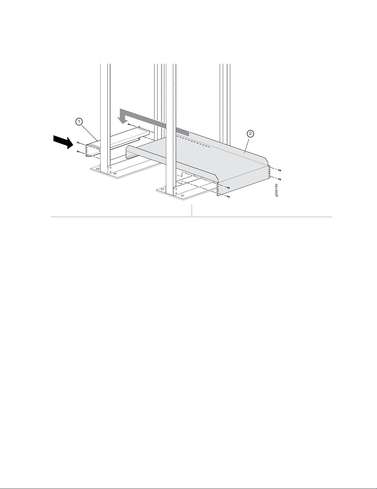
Figure 2: Installing the Mounting Hardware for a Four-Post Rack
g006189
2
1
10
2—1— Four-post mounting shelfRear support bracket
Remove the Center-Mounting Brackets
The center-mounting brackets are not used for a four-post rack, and must be removed from the chassis.
To remove the center-mounting brackets from the chassis:
1. Loosen the screws from each bracket (see Figure 3 on page 11).
2. Remove each bracket.
Page 11
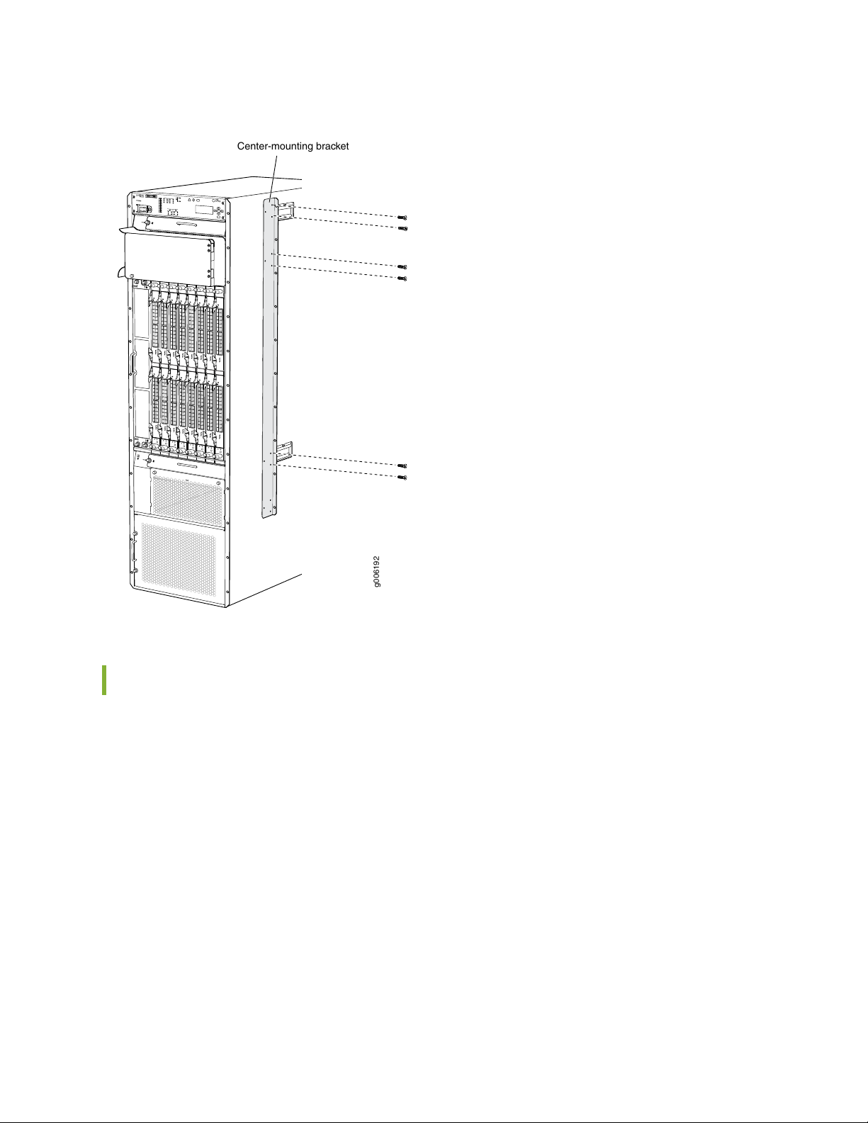
Figure 3: Removing the Center-Mounting Bracket
Center-mounting bracket
g006192
11
Install the PTX5000 Mounting Hardware for an Open-Frame Rack
1.
Install Cage Nuts, If Needed | 11
2.
Install the Open-Frame Rack Mounting Shelf | 13
Install Cage Nuts, If Needed
Insert cage nuts, if needed, into the holes listed in Table 3 on page 12 and Table 4 on page 12. The hole
distances are relative to the standard U division on the rack that is aligned with the bottom of the mounting
shelf and rear support bracket.
To install cage nuts in an open-frame rack:
1. On the rear side of both rack rails, insert cage nuts in the holes specified for the open-frame mounting
shelf (see Table 3 on page 12).
Page 12

2. On the front side of both rack rails, insert cage nuts in the holes specified for mounting the chassis (see
Table 4 on page 12).
Table 3: Mounting Hole Locations for Installing a PTX5000 Open-Frame Rack Shelf
Distance Above U DivisionHole
9.86 U17.25 in. (43.8 cm)30
8.86 U15.5 in. (39.4 cm)27
6.86 U12.0 in. (30.5 cm)21
4.86 U8.5 in. (21.6 cm)15
2.86 U5.0 in. (12.7 cm)9
0.86 U1.5 in. (3.8 cm)3
12
The holes in the center-mounting brackets are spaced at 3 U (5.25 in. or 13.3 cm).
Table 4: Mounting Hole Locations for Installing a Chassis in an Open-Frame Rack
Distance Above U DivisionHole
34.50 U60.38 in. (153.4 cm)104
31.50 U55.13 in. (140.0 cm)95
28.50 U49.88 in. (126.7 cm)86
25.50 U44.63 in. (113.3 cm)77
22.50 U39.38 in. (100.0 cm)68
19.50 U34.13 in. (86.7 cm)59
16.50 U28.88 in. (73.3 cm)50
13.50 U23.63 in. (60.0 cm)41
10.50 U18.38 in. (46.7 cm)32
7.50 U13.13 in. (33.3 cm)23
Page 13
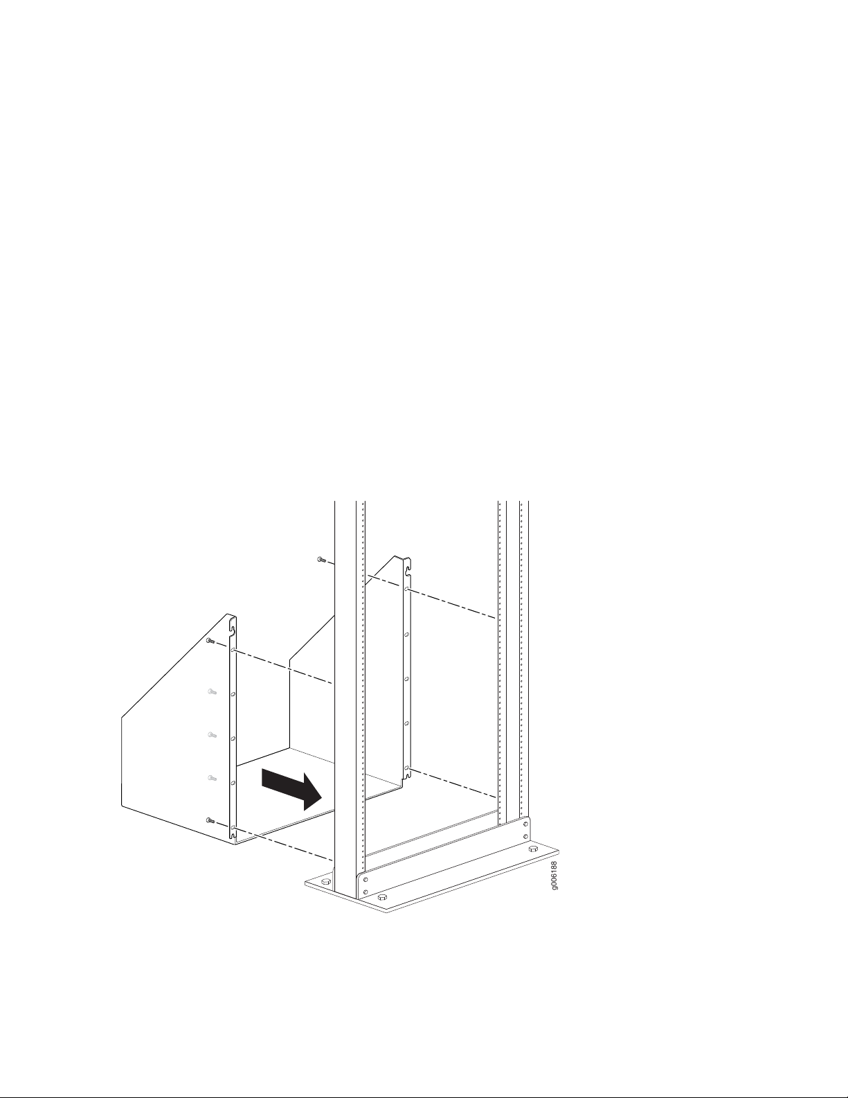
Install the Open-Frame Rack Mounting Shelf
g006188
Before mounting the chassis in an open-frame rack, you must first install the open-frame rack mounting
shelf.
To install the open-frame rack mounting shelf (see Figure 4 on page 13):
1. On the rear of each rack rail, partially insert a mounting screw into the highest hole specified in
Table 3 on page 12 for the open-frame rack mounting shelf.
2. Install the open-frame rack mounting shelf on the rack. Hang the shelf over the mounting screws by
using the keyhole slots located near the top of the shelf flanges.
3. Partially insert screws into the open holes in the flanges of the open-frame rack mounting shelf.
4. Tighten all the screws completely.
13
Figure 4: Installing the Mounting Hardware for an Open-Frame Rack
Page 14

Step 4: Install the PTX5000
CAUTION: Before installing the PTX5000:
Ensure that a mechanical lift is available for the installation. Because of the PTX5000
•
router’s size and weight—up to 1200 lb (544.3 kg) depending on configuration—you
must use a lift to install the chassis.
Have a qualified technician verify that the rack is strong enough to support the chassis
•
weight and is adequately supported at the installation site.
Ensure that the rack is in its permanent location and is secured to the building.
•
Ensure that the installation site allows adequate clearance for both airflow and
•
maintenance.
14
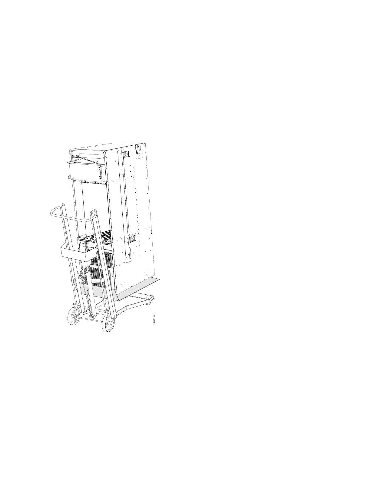
To install the PTX5000 by using a lift (see Figure 5 on page 15, Figure 6 on page 16, and
Figure 7 on page 17):
1. Load the PTX5000 onto the lift, making sure that the chassis rests securely on the mechanical lift.
CAUTION: Do not lift the PTX5000 by using the handles on the sides of the chassis.
Use these handles only to help position the PTX5000.
2. Using the lift, position the PTX5000 in front of the rack, centering it in front of the mounting shelf.
3. Lift the chassis slightly above the surface of the mounting shelf, and position it as close as possible to
the shelf.
4. Carefully slide the PTX5000 onto the mounting shelf, so that the bottom of the chassis and the mounting
shelf overlap by approximately 2 inches.
5. With four people pushing on the front-mounting flanges, slide the PTX5000 onto the mounting shelf
until the center-mounting brackets (open-frame racks) or front-mounting flanges (four-post racks)
contact the rack rails. The shelves ensure that the holes in the center-mounting brackets and the
front-mounting flanges of the chassis align with the holes in the rack rails.
Page 15
6. Visually inspect the alignment of the PTX5000. If the chassis is installed properly in the rack, all the
g006193
mounting screws on one side of the rack should be aligned with the mounting screws on the opposite
side, and the chassis should be level.
7. Install a mounting screw into each of the mounting holes aligned with the rack, starting from the bottom.
8. Move the lift away from the rack.
Figure 5: Loading the PTX5000 onto the Lift
15
The holes in the center-mounting brackets are spaced at 3 U (5.25 in. or 13.3 cm).
Page 16
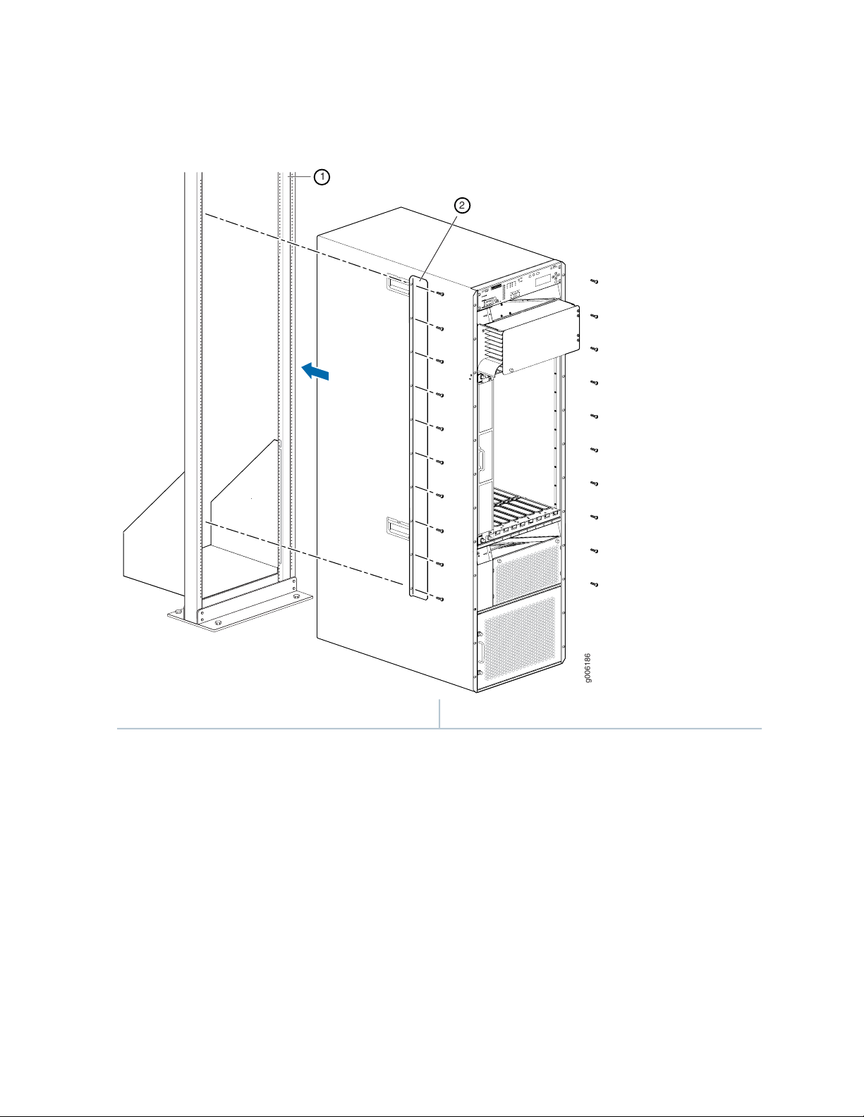
Figure 6: Installing the PTX5000 in an Open-Frame Rack
g006186
1
2
16
2—1— Center-mounting bracketOpen-frame rack
The holes in the front-mounting flanges are spaced at 3 U (5.25 in. or 13.3 cm).
Page 17
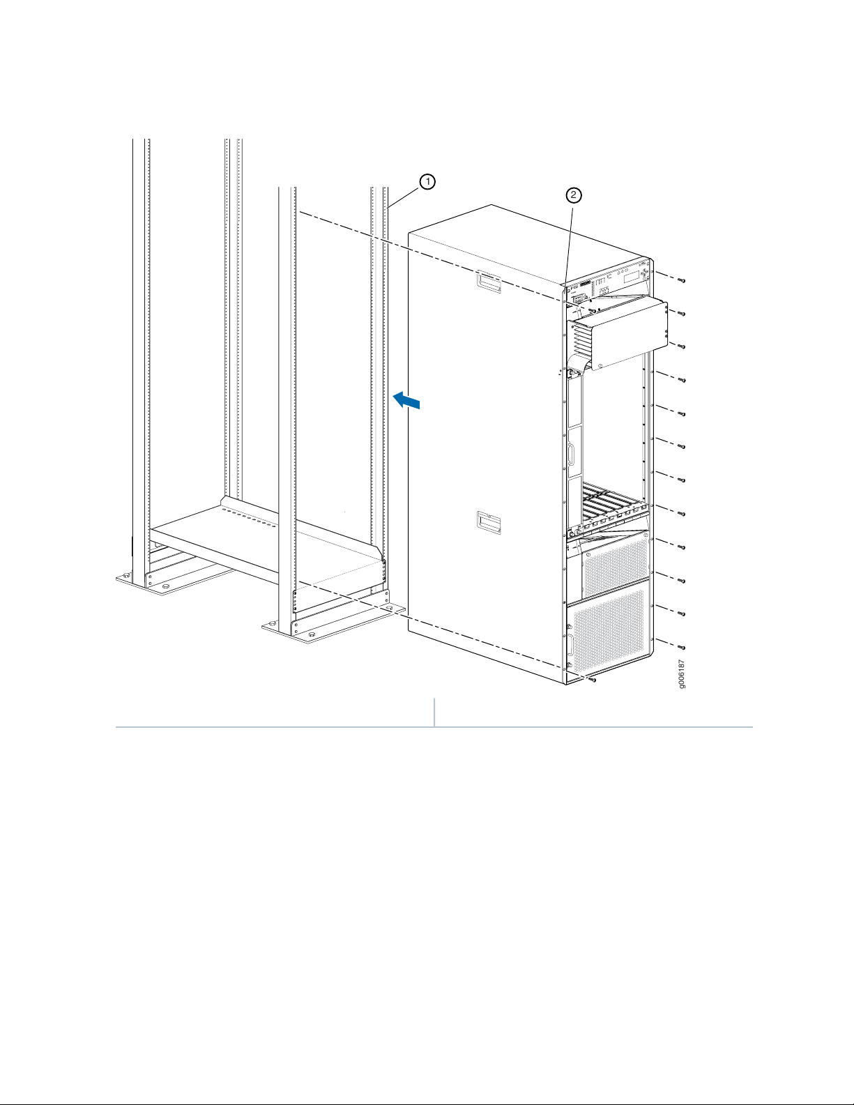
Figure 7: Installing the PTX5000 in a Four-Post Rack
g006187
1
2
17
2—1— Front-mounting flangeFour-post rack
Page 18
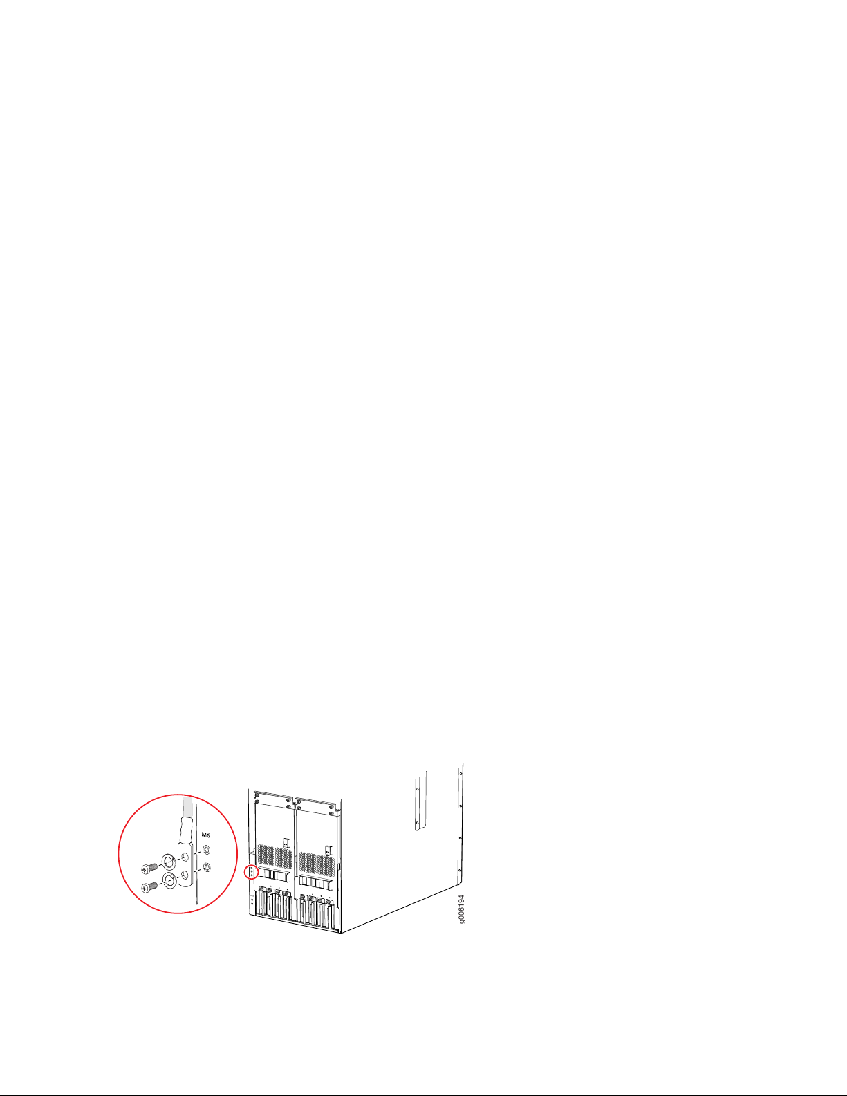
Step 5: Connect the PTX5000 Grounding Cable
g006194
You ground the PTX5000 by attaching a grounding cable to the chassis. You must provide the grounding
cable. Depending on your configuration, 0-AWG or 4-AWG (21.2 mm2) cable lugs are supplied with DC
PDUs, and can be used for grounding. See PTX5000 Chassis Grounding Cable and Lug Specifications in the
PTX5000 Packet Transport Router Hardware Guidefor more information.
To ground the PTX5000 (see Figure 8 on page 18):
1. Connect the grounding cable to a proper earth ground.
2. Verify that a licensed electrician has attached the cable lug provided with the PTX5000 to the grounding
cable.
3. Make sure that grounding surfaces are clean and brought to a bright finish before grounding connections
are made.
18
4. Place the grounding cable lug over the grounding points on the bottom rear of the chassis. The top pair
is sized for M6 screws, and the bottom pair is sized for UNC 1/4-20 screws. You can use either pair of
grounding points. UNC 1/4-20 screws are provided in the accessory kit.
5. Secure the grounding cable lug to the grounding points, first with the washers, then with the screws.
6. Verify that the grounding cabling is correct, that the grounding cable does not touch or block access
to the PTX5000 components, and that it does not drape where people could trip on it.
Figure 8: Connecting the Grounding Cable
Page 19

Step 6: Install the Front Door on a PTX5000
Optionally, you can install a door over the front card cage of the PTX5000. For more information, see the
following documentation:
Installing the Front Door on a PTX5000 in a Four-Post Rack
•
Installing the Front Door on a PTX5000 in an Open-Frame Rack
•
Step 7: Connect External Devices and PIC Cables to the PTX5000
19
IN THIS SECTION
Connect to a Console or Auxiliary Device | 19
Connect to a Network for Out-of-Band Management | 21
Connect the PIC Cables | 22
To connect external devices and PIC cables, perform the following procedures:
Connect to a Console or Auxiliary Device
Attach one or more management console or auxiliary devices to the Routing Engine ports on each Control
Board for management and service operations (see Figure 9 on page 20).
To connect the cables to a management console or auxiliary device:
1. Attach an electrostatic discharge (ESD) grounding strap to your bare wrist, and connect the strap to
one of the ESD points on the chassis.
2. If necessary, turn off the power to the console or auxiliary device.
Page 20
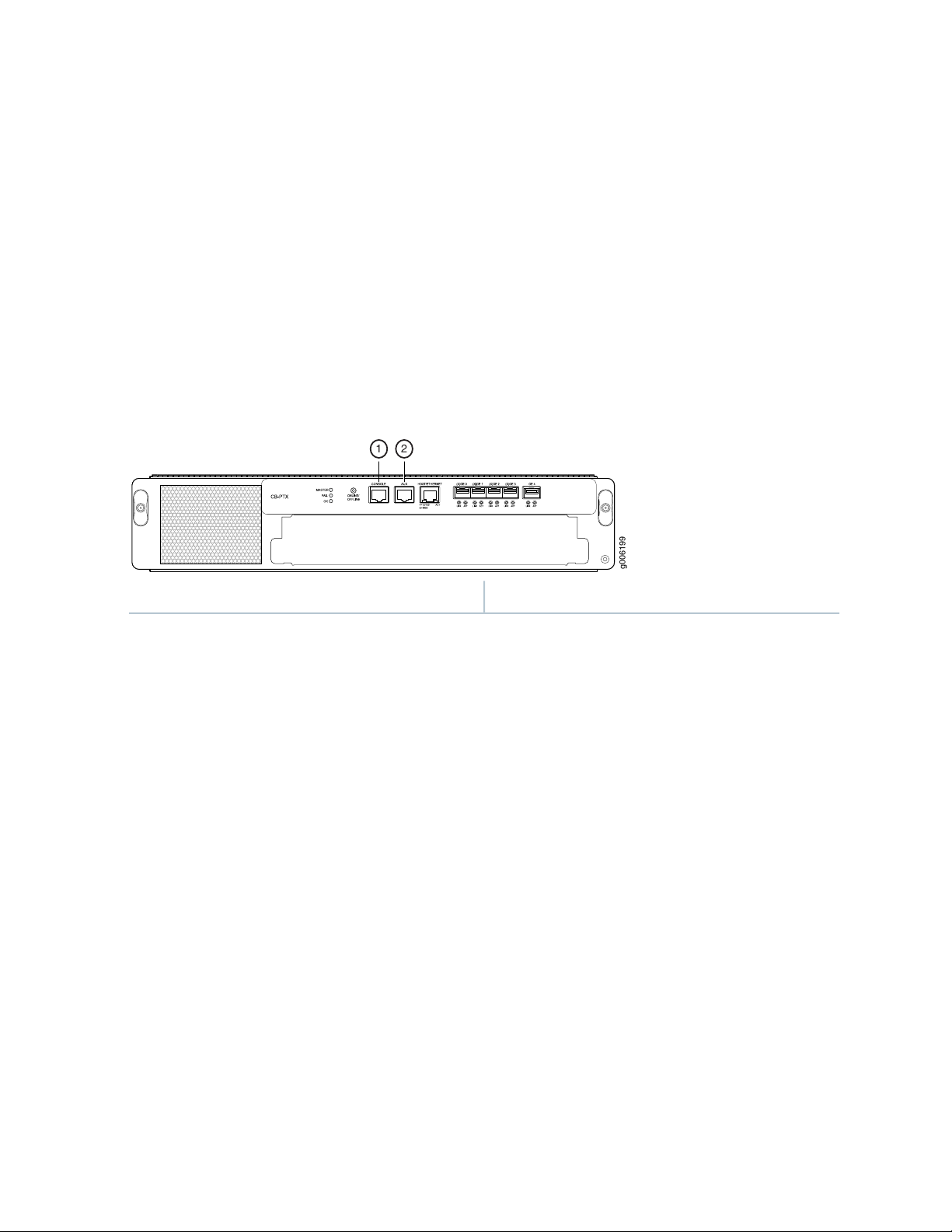
3. Plug one end of a copper cable with RJ-45 connectors into the CONSOLE or AUXILIARY port on the
g006199
1 2
Control Board in slot CB0. This port connects to the Routing Engine installed into the Control Board
in slot CB0.
4. Attach the other end of the cable to the console or auxiliary device.
5. Plug one end of another copper cable with RJ-45 connectors into the CONSOLE or AUXILIARY port
on CB1. This port connects to the Routing Engine installed into the control in slot CB1.
6. Attach the other end of the cable to the console or auxiliary device.
Figure 9: Connecting to the Console or Auxiliary Port on the Control Board
20
2—1— Auxiliary portConsole port
Page 21

Connect to a Network for Out-of-Band Management
To connect the Routing Engines in a PTX5000 to a network for management of the PTX5000, connect a
UTP Category 5 Ethernet cable with an RJ-45 connector to the HOST/ETHERNET port on a Control Board.
NOTE: For PTX5000 routers with two host subsystems, we recommend that you connect both
Control Boards to a network. One cable is provided in the accessory box. To connect another cable
to the HOST/ETHERNET port on the other Control Board, you must provide an additional cable.
To connect a cable to a network device:
1. Attach an ESD grounding strap to your bare wrist, and connect the strap to one of the ESD points on
the chassis.
CAUTION: During the initial installation before the chassis is grounded, you must
connect to an approved site ESD point. See the instructions for your site.
21
2. Plug one end of a UTP Category 5 Ethernet cable (Figure 10 on page 21 shows the connector) into the
HOST/ETHERNET port on the Control Board in slot CB0 (see Figure 11 on page 22). This port connects
to the Routing Engine installed into the Control Board in slot CB0.
3. Plug the other end of the cable into the network device.
4. Plug one end of another UTP Category 5 Ethernet cable into the HOST/ETHERNET port on the Control
Board in slot CB1. This port connects to the Routing Engine installed into the Control Board in slot
CB1.
5. Plug the other end of the cable into the network device.
Figure 10: Routing Engine Ethernet Cable Connector
Page 22
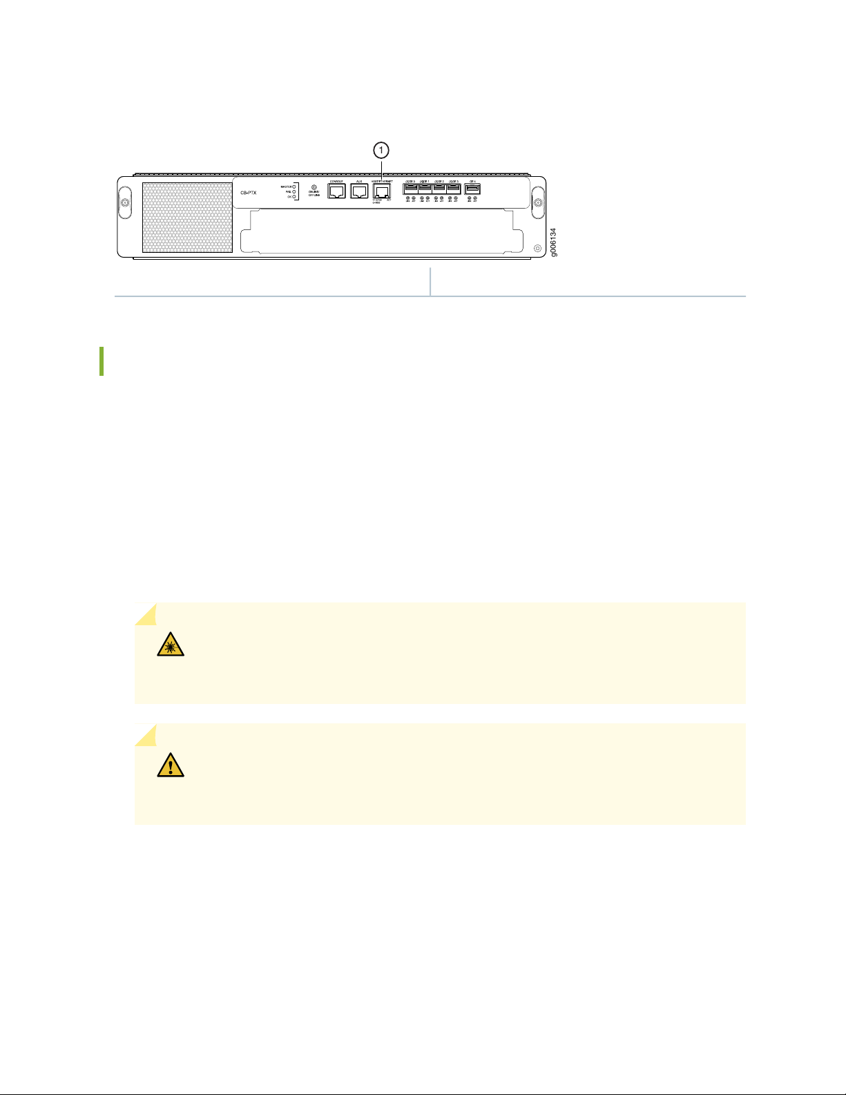
Figure 11: Connecting to the HOST/ETHERNET Port on the Control Board
g006134
1
1—HOST/ETHERNET port
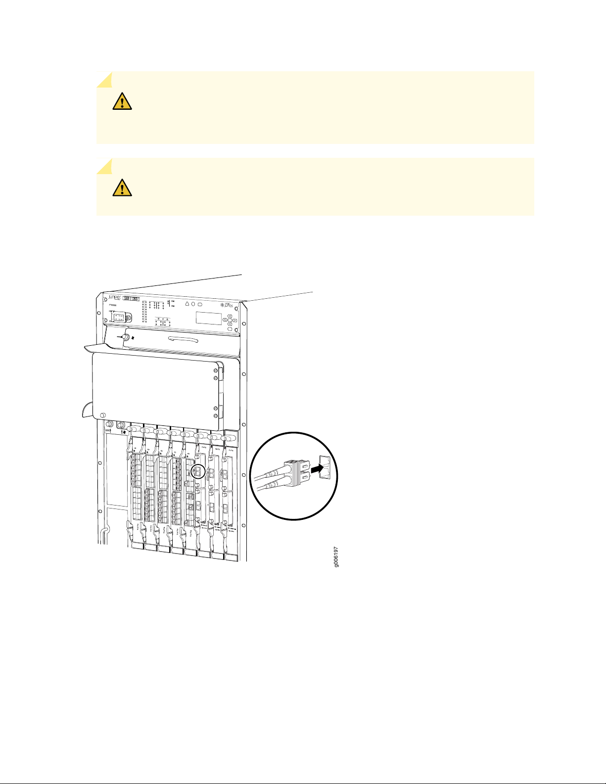
Connect the PIC Cables
The PTX5000 supports PICs that use various kinds of network cable, including multimode and single-mode
fiber-optic cable. For information about the type of cable used by each PIC, see the PTX Series Interface
Module Reference.
22
You connect PICs to the network by plugging in network cable. To connect cable to the PICs (see
Figure 12 on page 23):
1. Have ready a length of the type of cable used by the PIC. See the PTX Series Interface Module Reference.
2. If the PIC cable connector port is covered by a rubber safety plug, remove the plug.
WARNING: Do not look directly into a fiber-optic transceiver or into the ends of
fiber-optic cables. Fiber-optic transceivers and fiber-optic cable connected to a
transceiver emit laser light that can damage your eyes.
CAUTION: Do not leave a fiber-optic transceiver uncovered except when inserting
or removing cable. The safety cap keeps the port clean and prevents accidental
exposure to laser light.
3. Insert the cable connector into the cable connector port on the PIC faceplate.
4. Arrange the cable in the cable management system to prevent it from dislodging or developing stress
points. Secure the cable so that it is not supporting its own weight as it hangs to the floor. Place excess
cable out of the way in a neatly coiled loop in the cable management system. Placing fasteners on the
loop helps to maintain its shape.
Page 23
CAUTION: Avoid bending fiber-optic cable beyond its minimum bend radius. An arc
g006197
1
0
1
0
1
0
smaller than a few inches in diameter can damage the cable and cause problems that
are difficult to diagnose.
CAUTION: Do not let fiber-optic cable hang free from the connector. Do not allow
fastened loops of cable to dangle, which stresses the cable at the fastening point.
Figure 12: Connecting PIC Cables
23
Page 24

Step 8: Connect Power to the PTX5000 Router
IN THIS SECTION
Connect Power to the PTX5000 60-A DC Input Power Trays | 24
Connect Power to the PTX5000 120-A DC Input Power Trays | 29
Connect Power to the PTX5000 Three-Phase Delta AC PDUs | 32
Connect Power to the PTX5000 Three-Phase Wye AC PDUs | 36
Connect Power to the PTX5000 High Capacity DC PDUs | 42
Connect Power to the PTX5000 High Capacity Delta AC PDUs | 45
Connect Power to the PTX5000 High Capacity Wye AC PDUs | 52
Connect Power to the PTX5000 High Capacity Single-Phase AC PDUs | 57
24
Depending on the type of power distribution units (PDUs) you have installed, perform the appropriate
procedure:
Connect Power to the PTX5000 60-A DC Input Power Trays
To connect the DC source power cables to the 60-A DC inputs:
1. Verify that a properly rated customer-site circuit breaker for each DC power cable has been installed.
See PTX5000 DC Power Electrical Safety Guidelines in the PTX5000 Packet Transport Router Hardware
Guide for more information.
2. Switch off the customer-site circuit breakers. Ensure that the voltage across the DC power source cable
leads is 0 V and that there is no chance that the cable leads might become active during installation.
3. Verify that a licensed electrician has attached appropriate cable lugs to the DC power cables. See
PTX5000 DC Power Cable and Lugs Specifications in the PTX5000 Packet Transport Router Hardware
Guide for more information.
4. Attach an electrostatic discharge (ESD) grounding strap to your bare wrist, and connect the strap to
one of the ESD points on the chassis.
Page 25
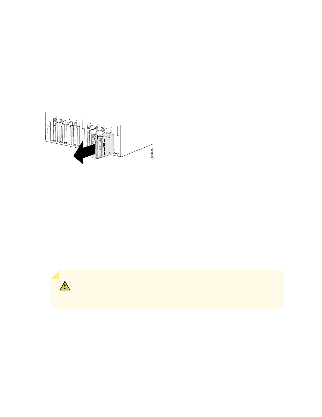
5. Switch the input power switches on the PDU faceplate to the off (O) position.
g006208
6. Loosen the captive screw that fastens the input power tray to the PDU .
7. Grasp the metal handle of the input power tray, and pull it out to remove the input power tray from
the PDU (see Figure 13 on page 25. The 60-A DC input power tray weighs 1.6 lb (0.7 kg).
Figure 13: Removing the 60-A DC Input Power Tray
25
8. Use a Phillips (+) screwdriver to loosen the screw on the metal input power tray cover.
9. Open the metal input power tray cover.
10. Loosen the cable restraints.
11. Remove the nuts from the DC power terminal studs.
12. Route the positive (+) DC source power cable through the cable restraint, and connect it to the RTN
–1 input terminal (see Figure 14 on page 26). Using a 7/16-in. (11-mm) nut driver, tighten the nut to
secure the cable lug to the input terminal (see Figure 15 on page 27).
CAUTION: You must use an appropriate torque-controlled tool to tighten the nuts.
Applying excessive torque damages the terminal studs and power supply. The maximum
torque that may be applied to this nut is 99 lb-in. (11 Nm).
Page 26

Figure 14: 60-A DC Input Terminals
g007229
-2 -1
-2 -1
RTN
-2 -1
-2 -1
-48V
(RTN)
26
Page 27

Figure 15: Connecting the DC Source Power Cable Lugs to an Input Power Tray
g006749
1
27
CAUTION: You must ensure that power connections maintain the proper polarity.
The power source cables might be labeled (+) and (–) to indicate their polarity. There
is no standard color coding for DC power cables. The color coding used by the external
DC power source at your site determines the color coding for the leads on the power
cables that attach to the terminal studs on each power supply.
CAUTION: All inputs on the DC PDU in slot PDU0 must be powered by dedicated
power feeds derived from feed A, and all inputs on the DC PDU in slot PDU1 must
be powered by dedicated power feeds derived from feed B. This configuration provides
the commonly deployed A/B feed redundancy for the system.
13. Route the positive (+) DC source power cable through the cable restraint, and connect it to the RTN
–2 input terminal (see Figure 14 on page 26). Using a 7/16-in. (11-mm) nut driver, tighten the nut to
secure the cable lug to the input terminal.
14. Route the negative (–) DC source power cable through the cable restraint, and connect it to the -48 V
–1 input terminal (see Figure 14 on page 26). Using a 7/16-in. (11-mm) nut driver, tighten the nut to
secure the cable lug to the input terminal.
Page 28

15. Route the negative (–) DC source power cable through the cable restraint, and connect it to the -48 V
g006652
–2 input terminal (see Figure 14 on page 26). Using a 7/16-in. (11-mm) nut driver, tighten the nut to
secure the cable lug to the input terminal (see Figure 15 on page 27).
16. Tighten the cable restraints over the DC power cables.
17. Verify that the source power cables are connected to the appropriate terminal: the positive (+) source
cable to the return terminals (labeled RTN) and the negative (–) source cable to the input terminals
(labeled –48V).
18. Close the input power tray cover, and secure it with the screw.
19. Insert the input power tray into the PDU (see Figure 16 on page 28).
20. Repeat the procedure for all input power trays in the PDU.
28
21. Repeat the procedure for the other PDU.
22. Verify that the DC power cables do not touch or block access to the components, and that they do not
drape where people could trip on them.
Figure 16: Installing a 60-A DC Input Power Tray
Page 29

Connect Power to the PTX5000 120-A DC Input Power Trays
g006208
To connect the DC source power cables to the 120-A DC inputs:
1. Ensure that the voltage across the DC power source cable leads is 0 V and that there is no chance that
the cable leads might become active during installation.
2. Attach an ESD grounding strap to your bare wrist, and connect the strap to one of the ESD points on
the chassis.
3. Switch the circuit breakers on the power distribution unit (PDU) faceplate to the off (O) position.
4. Loosen the captive screw that fastens the input power tray to the PDU .
5. Grasp the metal handle of the input power tray, and pull it out to remove the input power tray from
the PDU (see Figure 17 on page 29). The 120-A DC input power tray weighs 1.6 lb (0.7 kg).
29
Figure 17: Removing the 120-A DC Input Power Tray
6. Use a Phillips (+) screwdriver to loosen the screw on the metal input power tray cover.
7. Open the metal input power tray cover.
8. Loosen the cable restraints.
9. Remove the nuts from the DC power terminal studs.
10. Route the positive (+) DC source power cable lug through the left cable restraint.
11. Secure the positive (+) DC source power cable lug to the RTN (return) terminal, located on the left,
with a nut.
Use a 10-mm nut driver to tighten the nut.
Page 30

12. Route the negative (–) DC source power cable lug through the right cable restraint.
13. Attach the negative (–) DC source power cable lug to the –48V (input) terminal, located on the right
(see Figure 18 on page 31).
Use a 10-mm nut driver to tighten the nut.
CAUTION: You must use an appropriate torque-controlled tool to tighten the nuts.
Applying excessive torque damages the terminal studs and power supply. The maximum
torque that may be applied to this nut is 99 lb-in. (11 Nm).
CAUTION: You must ensure that power connections maintain the proper polarity.
The power source cables might be labeled (+) and (–) to indicate their polarity. There
is no standard color coding for DC power cables. The color coding used by the external
DC power source at your site determines the color coding for the leads on the power
cables that attach to the terminal studs on each power supply.
30
CAUTION: All inputs on the DC PDU in slot PDU0 must be powered by dedicated
power feeds derived from feed A, and all inputs on the DC PDU in slot PDU1 must
be powered by dedicated power feeds derived from feed B. This configuration provides
the commonly deployed A/B feed redundancy for the system.
Page 31

Figure 18: Connecting the DC Source Power Cable Lugs to an Input Power Tray
Cable restraint
g006184
31
14. Tighten the cable restraint over the DC power cables.
15. Verify that the source power cables are connected to the appropriate terminal: the positive (+) source
cable to the return terminal (labeled RTN) and the negative (–) source cable to the input terminal (labeled
–48V).
16. Close the input power tray cover, and secure it with the screw.
17. Insert the input power tray into the PDU (see Figure 19 on page 32).
18. Repeat the procedure for all input power trays in the PDU.
19. Repeat the procedure for the other PDU.
20. Verify that the DC power cables do not touch or block access to the components, and that they do not
drape where people could trip on them.
Page 32

Figure 19: Installing a 120-A DC Input Power Tray
g006185
g007220
Connect Power to the PTX5000 Three-Phase Delta AC PDUs
To connect the delta AC power cords to the three-phase delta AC PDUs (see Figure 26 on page 36):
1. Switch off the customer-site circuit breakers. Ensure that the voltage across the AC power source is 0
V and that there is no chance that the voltage might become active during installation.
32
2. Switch the circuit breaker and power OUTPUT switch on the PDU faceplate to the off (O) position.
3. Using a number 2 Phillips (+) screwdriver, remove the four screws from the metal retaining bracket
located on the lower right of the PDU. Remove the metal retaining bracket from the PDU (see
Figure 20 on page 32).
Figure 20: Removing the Metal Retaining Bracket from a Three-Phase Delta AC PDU
4. Unscrew the retaining nut from the AC power cord (see Figure 21 on page 33 and Figure 22 on page 33).
Page 33

Figure 21: Retaining Nut on a Three-Phase Delta AC Power Cord
g007224
1
2
g007215
2
1
1
33
2—1— Three-phase delta AC power cordRetaining nut
Figure 22: Removing the Retaining Nut from a Three-Phase Delta AC Power Cord
2—1— Three-phase delta AC power cordRetaining nut
5. Put the wires of the AC power cord through the hole of the metal retaining bracket, and screw the
retaining nut onto the AC power cord to secure it to the metal retaining bracket (see
Figure 23 on page 34).
Page 34

Figure 23: Connecting the Metal Retaining Bracket to Three-Phase Delta AC Power Cord
g007227
3
1
1
2
g007221
3—1— Three-phase delta AC power cordRetaining nut
2—Metal retaining bracket
6. Using a number 2 Phillips (+) screwdriver, loosen the two captive screws on the metal AC wiring
compartment. Open the metal door of the metal AC wiring compartment. Push the wires of the AC
power cord into the area for the metal retaining bracket, and pull the wires to the left toward the metal
AC wiring compartment. Using a number 2 Phillips (+) screwdriver, use the four screws on the metal
retaining bracket to secure the AC power cord to the PDU (see Figure 24 on page 34).
34
Figure 24: Connecting Power to a Three-Phase Delta AC PDU
Page 35

7. Connect the wires to the AC terminal block on the three-phase delta AC PDU (Figure 25 on page 35).
g007218
Using a 1/5-in. (5.5-mm) slotted screwdriver, loosen each of the input terminals or grounding point
screws, insert each wire into the grounding point or input terminal, and tighten the screw.
a. Insert the wire labeled GND into the grounding point.
b. Insert the wire labeled L1 into the L1 input terminal.
c. Insert the wire labeled L2 into the L2 input terminal.
d. Insert the wire labeled L3 into the L3 input terminal.
Figure 25: Connecting Ground and Power to a Three-Phase Delta AC PDU
35
8. Verify that the AC power wiring connections are correct.
9. Close the door to the metal AC wiring compartment, and use a number 2 Phillips (+) screwdriver to
tighten the two captive screws to secure the door to the metal AC wiring compartment.
10. Verify that the AC power cord does not touch or block access to PTX5000 components, and that it
does not drape where people could trip on it.
11. Repeat the procedure for the other three-phase delta AC PDU.
Page 36

Figure 26: Three-Phase Delta AC PDU
g007201
3
4
5
6
7
1
8
2
36
5—1— Circuit breakerTop installation handle
6—2— Wiring compartmentFront installation handle
7—3— Wiring compartment doorPower OUTPUT switch
8—4— Metal retaining bracketAir exhaust ventilation
Connect Power to the PTX5000 Three-Phase Wye AC PDUs
To connect an AC power cord to a three-phase wye AC PDU (see Figure 33 on page 41):
1. Switch off the customer-site circuit breakers. Ensure that the voltage across the AC power source is 0
V and that there is no chance that the voltage might become active during installation.
2. Switch the circuit breaker and power OUTPUT switch on the PDU faceplate to the off (O) position.
Page 37

3. Using a number 2 Phillips (+) screwdriver, loosen the four captive screws that fasten the metal retaining
g007220
g007224
1
2
bracket to the PDU, and remove the metal retaining bracket from the PDU (see Figure 27 on page 37).
Figure 27: Removing the Metal Retaining Bracket from a Three-Phase Wye AC PDU
37
4. Unscrew the retaining nut from the AC power cord (see Figure 28 on page 37 and Figure 29 on page 38).
Figure 28: Retaining Nut on a Three-Phase Wye AC Power Cord
2—1— Three-phase wye AC power cordRetaining nut
Page 38

Figure 29: Removing the Retaining Nut from a Three-Phase Wye AC Power Cord
g007215
2
1
1
g007228
3
1
1
2
2—1— Three-phase wye AC power cordRetaining nut
5. Put the wires of the AC power cord through the hole of the metal retaining bracket, and screw the
retaining nut onto the AC power cord to secure it to the metal retaining bracket (see
Figure 30 on page 38).
Figure 30: Connecting the Metal Retaining Bracket to the Three-Phase Wye AC Power Cord
38
3—1— Three-phase wye AC power cordRetaining nut
2—Metal retaining bracket
6. Using a number 2 Phillips (+) screwdriver, loosen the two captive screws on the metal AC wiring
compartment. Open the metal door of the metal AC wiring compartment. Push the wires of the AC
power cord into the area for the metal retaining bracket, and pull the wires to the left toward the metal
AC wiring compartment. Using a number 2 Phillips (+) screwdriver, use the four captive screws on the
metal retaining bracket to secure the AC power cord to the PDU (see Figure 31 on page 39).
Page 39

Figure 31: Connecting Power to a Three-Phase Wye AC PDU
g007223
7. Connect the wires to the AC terminal block on the three-phase wye AC power supply
(Figure 32 on page 40). Using a 1/5-in. (5.5-mm) slotted screwdriver, loosen each of the input terminals
or grounding point screws, insert each wire into the grounding point or input terminal, and tighten the
screw.
39
a. Insert the wire labeled GND into the grounding point.
b. Insert the wire labeled L1 into the L1 input terminal.
c. Insert the wire labeled L2 into the L2 input terminal.
d. Insert the wire labeled L3 into the L3 input terminal.
e. Insert the wire labeled N into the N input terminal
CAUTION: To avoid damage to the PDU, do not connect the neutral wire to the
L1, L2, or L3 input terminals.
Page 40

Figure 32: Connecting Power to the Three-Phase Wye AC Power Supply
g007219
8. Verify that the AC power wiring connections are correct.
40
9. Close the door to the metal AC wiring compartment, and use a number 2 Phillips (+) screwdriver to
tighten the two captive screws to secure the door to the metal AC wiring compartment.
10. Verify that the AC power cord does not touch or block access to router components, and that it does
not drape where people could trip on it.
11. Repeat the procedure for the other three-phase wye AC PDU.
Page 41

Figure 33: Three-Phase Wye AC PDU
g007200
3
2
4
5
6
7
1
8
41
5—1— Circuit breakerTop installation handle
6—2— Wiring compartmentFront installation handle
7—3— Wiring compartment doorPower OUTPUT switch
8—4— Metal retaining bracketAir exhaust ventilation
Page 42

Connect Power to the PTX5000 High Capacity DC PDUs
To connect the DC source power cables to the High Capacity DC inputs:
1. Verify that a properly rated customer-site circuit breaker for each DC power cable has been installed.
See PTX5000 DC Power Electrical Safety Guidelines in the PTX5000 Packet Transport Router Hardware
Guide for more information.
2. Switch off the customer-site circuit breakers. Ensure that the voltage across the DC power source cable
leads is 0 V and that there is no chance that the cable leads might become active during installation.
3. Verify that a licensed electrician has attached appropriate cable lugs to the DC power cables. See
PTX5000 DC Power Cable and Lugs Specifications in the PTX5000 Packet Transport Router Hardware
Guide for more information.
4. Attach an ESD grounding strap to your bare wrist, and connect the strap to one of the ESD points on
the chassis.
42
5. Move the power switch to the standby ( ) position.
6. Unfasten the screw using a number 2 Phillips (+) screwdriver and remove the terminal block safety
cover.
7. Remove the nuts from the DC power terminal studs.
8. Connect the positive (+) DC source power cable to the RTN input terminal (see Figure 34 on page 43).
Using a 7/16-in. (11-mm) nut driver, tighten the nut to secure the cable lug to the input terminal (see
Figure 35 on page 43).
The terminal studs for each PSM are numbered on the faceplate. For example, the DC input terminals
for PSM0 are PSM0_1 and PSM0_2, in the first and second rows of the terminal blocks. There are
sixteen 60-A input terminals for the eight PSMs supported for each PDU.
CAUTION: You must use an appropriate torque-controlled tool to tighten the nuts.
Applying excessive torque damages the terminal studs and power supply. The maximum
torque that may be applied to this nut is 65 lb-in. (7.3 Nm).
Page 43

Figure 34: High Capacity DC Input Terminals
-48V/60A
-48V/60A
g000320
43
Figure 35: Connecting the DC Source Power Cable Lugs to an Input Power Terminal
Page 44

CAUTION: You must ensure that power connections maintain the proper polarity.
The power source cables might be labeled (+) and (–) to indicate their polarity. There
is no standard color coding for DC power cables. The color coding used by the external
DC power source at your site determines the color coding for the leads on the power
cables that attach to the terminal studs on each power supply.
CAUTION: All inputs on the DC PDU in slot PDU0 must be powered by dedicated
power feeds derived from feed A, and all inputs on the DC PDU in slot PDU1 must
be powered by dedicated power feeds derived from feed B. This configuration provides
the commonly deployed A/B feed redundancy for the system.
9. Connect the negative (–) DC source power cable to the -48 V/60A input terminal (see
Figure 35 on page 43). Using a 7/16-in. (11-mm) nut driver, tighten the nut to secure the cable lug to
the input terminal.
44
10. Verify that the source power cables are connected to the appropriate terminal: the positive (+) source
cable to the return terminals (labeled RTN) and the negative (–) source cable to the input terminals
(labeled –48V/60A).
11. Replace the terminal block safety cover and ensure that the cables fit into the slots of the safety cover.
12. Repeat the procedure for the input power terminals for all the PSMs in the PDU.
13. Repeat the procedure for the other PDU.
14. Verify that the DC power cables do not touch or block access to the components, and that they do not
drape where people could trip on them.
Page 45

Connect Power to the PTX5000 High Capacity Delta AC PDUs
To connect an AC power cord to a High Capacity Delta AC PDU (see Figure 36 on page 45):
Figure 36: High Capacity Delta AC PDU
45
6—1— Input voltage LEDTop installation handle
7—2— Wiring compartmentFront installation handle
8—3— Power input cord selection switchPDU OK LED
9—4— Metal retaining bracketPower switch labeled (|) for the on position and ( )
for the standby position.
10—5— Wiring compartment doorAir exhaust ventilation
1. Switch off the customer-site circuit breakers. Ensure that the voltage across the AC power source is 0
V and that there is no chance that the voltage might become active during installation.
2. Switch the power switch on the PDU faceplate to the standby ( ) position.
3. Using a number 2 Phillips (+) screwdriver, remove the four screws from the metal retaining bracket
located on the lower right of the PDU. Remove the metal retaining bracket from the PDU (see
Figure 37 on page 46).
Page 46

Figure 37: Removing the Metal Retaining Bracket from a High Capacity Delta AC PDU
g007224
1
2
4. Unscrew the retaining nut from the AC power cord (see Figure 38 on page 46 and Figure 39 on page 47).
Figure 38: Retaining Nut on an AC Power Cord
46
2—1— AC power cordRetaining nut
NOTE: This is a representational image. The High Capacity Delta AC PDU supports three power
cords for 60 A, 100 A, and 150 A, respectively.
Page 47

Figure 39: Removing the Retaining Nut from an AC Power Cord
g007215
2
1
1
2—1— AC power cordRetaining nut
5. Put the wires of the AC power cord through the hole of the metal retaining bracket, and screw the
retaining nut onto the AC power cord to secure it to the metal retaining bracket (see
Figure 40 on page 47).
Figure 40: Connecting the Metal Retaining Bracket to an AC Power Cord
47
NOTE: If you are using 150 A power, you must use a metal bracket that is larger than the default
metal bracket. This bracket is shipped along with the High Capacity Delta AC PDUs. Labels on
top of the metal brackets specify the power cords that can be used for each bracket (see
Figure 41 on page 48). The installation procedure to connect the metal bracket to the PDU is
the same for both metal brackets.
Page 48

Figure 41: Metal Brackets for Power Cords
50mm
48
Metal Bracket with label Use for 740-053918,
740-059634 Power Cords—740-053918 indicates
the 100-A power cord and 740-059634 the 150-A
power cord for the High Capacity Delta AC PDU.
2—1— Metal Bracket with label Use for 740-053919,
740-059635, 740-035459 Power
Cords—740-053919 indicates the power cord for
the High Capacity Delta AC PDU. 740-059635
indicates the 100-A power cord and 740-035459
the 60-A power cord.
6. Attach the power cord to the PDU:
a. Using a number 2 Phillips (+) screwdriver, loosen the two captive screws on the metal AC wiring
compartment.
b. Open the metal door of the metal AC wiring compartment.
c. Push the wires of the AC power cord into the area for the metal retaining bracket, and pull the wires
to the left toward the metal AC wiring compartment.
d. Using a number 2 Phillips (+) screwdriver, use the four screws on the metal retaining bracket to
secure the AC power cord to the PDU (see Figure 42 on page 49).
Page 49

Figure 42: Attaching the Power Cord to the High Capacity Delta AC PDU
7. Connect the wires to the AC terminal block on the High Capacity Delta AC PDU (Figure 43 on page 50).
Using a 1/5-in. (5.5-mm) slotted screwdriver, loosen each of the input terminal screws and the grounding
point screw, insert each wire into the grounding point or input terminal, and tighten the screw.
a. Insert the wire labeled GND into the grounding point.
49
b. Insert the wire labeled L1 into the L1 input terminal.
c. Insert the wire labeled L2 into the L2 input terminal.
d. Insert the wire labeled L3 into the L3 input terminal.
Page 50

Figure 43: Connecting Ground and Power to a High Capacity Delta AC PDU
50
8. Verify that the AC power wiring connections are correct.
9. Close the door to the metal AC wiring compartment, and use a number 2 Phillips (+) screwdriver to
tighten the two captive screws to secure the door to the metal AC wiring compartment.
10. Verify that the AC power cord does not touch or block access to PTX5000 components, and that it
does not drape where people could trip on it.
11. Before you power on the PDU, select the switch setting corresponding to the AC input power cord
that is connected to the PDU. Figure 44 on page 51 shows an ampere switch, located inside the wiring
compartment.
If CBL-PTX-AC-D cable is used, set the switch to 60A.
•
If CBL2-PTX-100AC-D cable is used, set the switch to 100A.
•
If CBL2-PTX-150AC-D cable is used, set the switch to 150A.
•
You can verify the switch setting by using the show chassis environment pdu command. The command
displays the input power rating as shown in the following example:
show chassis environment pdu 0
Page 51

PDU 0 status:
State Online
BoostConv OK
Feed Switch 150Amps <<<===
Hours Used 142
Firmware Version (MCU1) 03.04
Figure 44: Ampere Switch
51
WARNING: If you set the ampere switch in the wiring compartment incorrectly, the
AC power cord might overheat. Setting the ampere switch incorrectly might also cause
the site circuit breaker to trip.
NOTE: The system software gets the system power configuration from the PDU and displays
it in the output of the show chassis environment pdu command. Depending on the setting, the
system software limits the system configuration (FPCs and PICs) to keep the power demand
within the maximum output power available from the PDU.
NOTE: In a redundant system with two PDUs, the PDUs share the load. If the ampere switch
setting of one PDU is lower than the other, Junos OS reduces the rating of the other PDU to
the lower value.
12. Repeat the procedure for the other High Capacity Delta AC PDU.
Page 52

Connect Power to the PTX5000 High Capacity Wye AC PDUs
To connect an AC power cord to a High Capacity Wye AC PDU (see Figure 45 on page 52):
Figure 45: High Capacity Wye AC PDU
52
6—1— Circuit breakerTop Installation handle
7—2— Input voltage LEDFront installation handle
8—3— Wiring compartmentPDU OK LED
9—4— Metal retaining bracketPower switch labeled (|) for the on position and ( )
for the standby position.
10—5— Wiring compartment doorAir exhaust ventilation
To connect an AC power cord to a High Capacity Wye AC PDU (see Figure 45 on page 52):
1. Switch off the customer-site circuit breakers. Ensure that the voltage across the AC power source is 0
V and that there is no chance that the voltage might become active during installation.
2. Move the circuit breaker on the faceplate of the PDU to the off position.
3. Move the power switch located on the faceplate of the PDU to the standby ( ) position.
Page 53

4. Using a number 2 Phillips (+) screwdriver, loosen the four captive screws that fasten the metal retaining
g007220
g007224
1
2
bracket to the PDU, and remove the metal retaining bracket from the PDU (see Figure 46 on page 53).
Figure 46: Removing the Metal Retaining Bracket from a High Capacity Wye AC PDU
53
5. Unscrew the retaining nut from the AC power cord (see Figure 47 on page 53 and Figure 48 on page 54).
Figure 47: Retaining Nut on an AC Power Cord
2—1— AC power cordRetaining nut
Page 54

Figure 48: Removing the Retaining Nut from an AC Power Cord
g007215
2
1
1
g007228
3
1
1
2
2—1— AC power cordRetaining nut
6. Put the wires of the AC power cord through the hole of the metal retaining bracket, and screw the
retaining nut onto the AC power cord to secure it to the metal retaining bracket (see
Figure 49 on page 54).
Figure 49: Connecting the Metal Retaining Bracket to the AC Power Cord
54
3—1— AC power cordRetaining nut
2—Metal retaining bracket
Page 55

7. Attach the power cord to the PDU:
a. Using a number 2 Phillips (+) screwdriver, loosen the two captive screws on the metal AC wiring
compartment.
b. Open the metal door of the metal AC wiring compartment.
c. Push the wires of the AC power cord into the area for the metal retaining bracket, and pull the wires
to the left toward the metal AC wiring compartment.
d. Using a number 2 Phillips (+) screwdriver, use the four captive screws on the metal retaining bracket
to secure the AC power cord to the PDU (see Figure 50 on page 55).
Figure 50: Connecting Power to a High Capacity Wye AC PDU
55
8. Connect the wires to the AC terminal block on the High Capacity Wye AC PDU (see
Figure 51 on page 56). Using a 1/5-in. (5.5-mm) slotted screwdriver, loosen each of the input terminal
screws and the grounding point screw, insert each wire into the grounding point or input terminal, and
tighten the screw.
a. Insert the neutral wire labeled GND into the grounding point.
b. Insert the wire labeled L1 into the L1 input terminal.
c. Insert the wire labeled L2 into the L2 input terminal.
d. Insert the wire labeled L3 into the L3 input terminal.
e. Insert the wire labeled N into the N input terminal.
Page 56

CAUTION: To avoid damage to the PDU, do not connect the neutral wire to the
L1, L2, or L3 input terminal.
Figure 51: Connecting Power to the High Capacity Wye AC PDU
56
9. Verify that the AC power wiring connections are correct.
10. Close the door to the metal AC wiring compartment, and use a number 2 Phillips (+) screwdriver to
tighten the two captive screws to secure the door to the metal AC wiring compartment.
11. Verify that the AC power cord does not touch or block access to PTX5000 components, and that it
does not drape where people could trip on it.
12. Repeat the procedure for the other High Capacity Wye AC PDU.
Page 57

Connect Power to the PTX5000 High Capacity Single-Phase AC PDUs
The high-capacity single-phase AC PDU accepts eight single-phase 30-A or eight single-phase 20-A,
200–250 VAC L-L input power. One 30-A or 20-A input power provides dedicated input power to each
PSM.
To connect the AC power cords to the single-phase AC PDUs (see Figure 52 on page 57):
Figure 52: Connecting the Source Power to a High Capacity Single-Phase AC PDU
57
1. Switch off the customer-site circuit breakers. Ensure that the voltage across the AC power source is 0
V and that there is no chance that the voltage might become active during installation.
2. Move the power output switch on the PDU faceplate to the standby ( ) position.
3. Using a number 2 Phillips (+) screwdriver, loosen the two screws from the metal door of the metal AC
wiring compartment—located in the middle of the PDU faceplate for 20-A inputs and lower part of the
PDU for the 30-A inputs.
4. Using a number 2 Phillips (+) screwdriver, loosen the screw on the 20-A input terminal and plug in the
connector (see Figure 53 on page 58 and Figure 54 on page 59). Tighten the screw after plugging in
the connector.
Page 58

NOTE: The 30-A connector does not have a clamp, but it has its own integral clip for locking
the connector.
Figure 53: Plug Type for the 20-A Connector
58
Page 59

Figure 54: Connecting 20-A Inputs to a High Capacity Single-Phase AC PDU
59
5. Connect up to eight inputs (20-A or 30-A) to the PDU. See Figure 55 on page 60 and
Figure 56 on page 61.
Page 60

Figure 55: Plug Types for the 30-A Connector
60
Page 61

Figure 56: Connecting 30-A Inputs to a High Capacity Single-Phase AC PDU
61
6. Verify that the AC power wiring connections are correct.
7. Verify that the AC power cord does not touch or block access to PTX5000 components, and that it
does not drape where people could trip on it.
8. Repeat the procedure for the other single-phase AC PDU.
Page 62

Step 9: Power On the PTX5000
IN THIS SECTION
Power On a PTX5000 with 60-A DC PDUs | 62
Power On a PTX5000 with 120-A DC PDUs | 64
Power On a PTX5000 with High Capacity DC PDUs | 66
Power On a PTX5000 with Three-Phase AC PDUs | 68
Power On a PTX5000 with High Capacity Single-Phase AC PDUs | 69
Depending on the type of PDUs you have installed, perform the appropriate procedure:
62
Power On a PTX5000 with 60-A DC PDUs
To power on the DC-powered PTX5000 with 60-A DC PDUs and 60-A DC PSMs:
NOTE: After powering off a power supply, you must wait at least 60 seconds before powering it
on again.
1. Verify that the power distribution units (PDUs) and power supply modules (PSMs) are fully inserted in
the chassis and that the captive screws on the faceplates are tightened.
2. Verify that an external management device is connected to one of the Routing Engine ports on the
Control Board (AUXILIARY or CONSOLE).
NOTE: The management Ethernet port labeled HOST/ETHERNET on the Control Board is not
available until after the initial software configuration. You can monitor the startup process during
the initial installation using devices connected to the AUXILIARY or CONSOLE ports.
3. Turn on power to the external management device.
Page 63

4. Switch on the customer-site circuit breakers to provide voltage to the DC power source cables.
5. Attach an electrostatic discharge (ESD) grounding strap to your bare wrist, and connect the strap to
one of the ESD points on the chassis.
6. Verify that the green DC IN LEDs for both inputs on the PDU faceplate are lit steadily green, indicating
that the inputs are receiving power.
7. Switch all the input power switches on one of the PDUs to the on (|) position.
8. Verify that the green SW ON LEDs on the PDU faceplate are lit steadily. The SW ON LEDs blink
momentarily, then light steadily to indicate that the input power switches are on.
NOTE: After a PDU is powered on, it can take up to 60 seconds for status indicators—such as
the LEDs on the PDU and PSMs, the command output displays, and messages on the LCD
display on the craft interface—to indicate that the PDU and PSMs are functioning normally.
Ignore error indicators that appear during the first 60 seconds.
63
9. Move the OUTPUT power switch on the PDU to the on (|) position.
10. Verify that the PDU OK LED on the PDU faceplate is lit steadily and that the FAULT LED is off, indicating
that the PDU is correctly installed and is functioning properly.
NOTE: If the PDU OK LED does not light steadily, repeat the installation and cabling procedures.
11. Check the LEDs on the PSMs. For each PSM, verify that the Input OK and Output OK LEDs are lit
steadily green, and that the Fault LED is off.
NOTE: If the Input OK and Output OK LEDs do not light steadily or if the FAULT LED is lit,
see Troubleshooting the PTX5000 Power System in the PTX5000 Packet Transport Router Hardware
Guide.
12. On the external management device connected to the Routing Engine, monitor the startup process to
verify that the system has booted properly.
13. Repeat steps 7 through 12 for the other PDU.
Page 64

NOTE: The Routing Engine boots as the PDU completes its startup sequence. If the Routing Engine
finishes booting and you need to power off the system, see Powering Off the PTX5000 in the
PTX5000 Packet Transport Router Hardware Guide.
After powering on a power supply, you must wait at least 60 seconds before powering it off.
Power On a PTX5000 with 120-A DC PDUs
To power on the DC-powered PTX5000 with 120-A DC PDUs and 120-A DC PSMs:
NOTE: After powering off a power supply, you must wait at least 60 seconds before powering it
on again.
64
1. Verify that the power distribution units (PDUs) and power supply modules (PSMs) are fully inserted in
the chassis and that the captive screws on the faceplates are tightened.
2. Verify that an external management device is connected to one of the Routing Engine ports on the
Control Board (AUXILIARY or CONSOLE).
NOTE: The management Ethernet port labeled HOST/ETHERNET on the Control Board is not
available until after the initial software configuration. You can monitor the startup process during
the initial installation using devices connected to the AUXILIARY or CONSOLE ports.
3. Turn on power to the external management device.
4. Switch on the customer-site circuit breakers to provide voltage to the DC power source cables.
5. Attach an electrostatic discharge (ESD) grounding strap to your bare wrist, and connect the strap to
one of the ESD points on the chassis.
6. Verify that the green –48 V 120 A LEDs on the PDU faceplate are lit steadily green, indicating that the
inputs are receiving power.
7. Switch all the circuit breakers on one of the PDUs to the on (|) position.
Page 65

8. Verify that the green CB ON LEDs on the PDU faceplate are lit steadily. The CB ON LEDs blink
momentarily, then light steadily to indicate that the circuit breakers are on.
NOTE: After a PDU is powered on, it can take up to 60 seconds for status indicators—such as
the LEDs on the PDU and PSMs, the command output displays, and messages on the LCD
display on the craft interface—to indicate that the PDU and PSMs are functioning normally.
Ignore error indicators that appear during the first 60 seconds.
9. Move the OUTPUT power switch on the PDU to the on (|) position.
10. Verify that the PDU OK LED on the PDU faceplate is lit steadily and that the FAULT LED is off, indicating
that the PDU is correctly installed and is functioning properly.
NOTE: If the PDU OK LED does not light steadily, repeat the installation and cabling procedures.
65
11. Check the LEDs on the PSMs. For each PSM, verify that the Input OK and Output OK LEDs are lit
steadily green, and that the Fault LED is off.
NOTE: If the Input OK and Output OK LEDs do not light steadily or if the FAULT LED is lit,
see Troubleshooting the PTX5000 Power System in the PTX5000 Packet Transport Router Hardware
Guide.
12. On the external management device connected to the Routing Engine, monitor the startup process to
verify that the system has booted properly.
13. Repeat steps 7 through 12 for the other PDU.
NOTE: The Routing Engine boots as the PDU completes its startup sequence. If the Routing Engine
finishes booting and you need to power off the system, see the Powering Off the PTX5000 in the
PTX5000 Packet Transport Router Hardware Guide.
After powering on a power supply, you must wait at least 60 seconds before powering it off.
Page 66

Power On a PTX5000 with High Capacity DC PDUs
To power on the DC-powered PTX5000 with High Capacity DC PDUs and High Capacity DC PSMs:
NOTE: After powering off a power supply, you must wait at least 60 seconds before powering it
on again.
1. Verify that the power distribution units (PDUs) and power supply modules (PSMs) are fully inserted in
the chassis and that the captive screws on the faceplates are tightened.
2. Verify that an external management device is connected to one of the Routing Engine ports on the
Control Board (AUXILIARY or CONSOLE).
NOTE: The management Ethernet port labeled HOST/ETHERNET on the Control Board is not
available until after the initial software configuration. You can monitor the startup process during
the initial installation using devices connected to the AUXILIARY or CONSOLE ports.
66
3. Turn on power to the external management device.
4. Switch on the customer-site circuit breakers to provide voltage to the DC power source cables.
5. Attach an electrostatic discharge (ESD) grounding strap to your bare wrist, and connect the strap to
one of the ESD points on the chassis.
6. Switch the power switch on one of the PDUs to the on (|) position.
7. Verify that the green PDU OK LED is lit steadily green, indicating that the inputs are receiving power.
8. Verify that the -1 and -2 LEDs for each installed PSM are lit green. Also check the input 1 OK, input 2
OK, output OK, and fault ( ) LEDs on each PSM.
NOTE: The -1 and -2 LEDs are lit depending on the number of PSMs connected to each PDU.
A minimum of three PSMs are required out of a maximum of eight per PDU. Also, each PSM
has LEDs indicating input and output status.
Page 67

NOTE: After a PDU is powered on, it can take up to 60 seconds for status indicators—such as
the LEDs on the PDU and PSMs, the command output displays, and messages on the LCD
display on the craft interface—to indicate that the PDU and PSMs are functioning normally.
Ignore error indicators that appear during the first 60 seconds.
NOTE: If the PDU OK and PSM LEDs do not light steadily or if the fault ( ) LED on the PSM
is lit, see Troubleshooting the PTX5000 Power System in the PTX5000 Packet Transport Router
Hardware Guide.
9. On the external management device connected to the Routing Engine, monitor the startup process to
verify that the system has booted properly.
67
10. Repeat Step 6 through Step 8 for the other PDU.
NOTE: The Routing Engine boots as the PDU completes its startup sequence. If the Routing Engine
finishes booting and you need to power off the system, see the Powering Off the PTX5000 in the
PTX5000 Packet Transport Router Hardware Guide.
After powering on a power supply, you must wait at least 60 seconds before powering it off.
Page 68

Power On a PTX5000 with Three-Phase AC PDUs
To power on the AC-powered PTX5000 with three-phase delta AC PDUs or three-phase wye AC PDUs,
and with AC PSMs:
NOTE: After powering off a PDU, you must wait at least 60 seconds before powering it on again.
1. Verify that the power distribution units (PDUs) and power supply modules (PSMs) are fully inserted in
the chassis and that the captive screws on the faceplates are tightened.
2. Verify that an external management device is connected to one of the Routing Engine ports on the
Control Board (AUXILIARY or CONSOLE).
NOTE: The management Ethernet port labeled HOST/ETHERNET on the Control Board is not
available until after the initial software configuration. You can monitor the startup process during
the initial installation using devices connected to the AUXILIARY or CONSOLE ports.
68
3. Turn on power to the external management device.
4. Switch on the customer-site circuit breakers to provide voltage to the AC power cords.
5. Verify that the PDUs are receiving power.
On the three-phase wye AC PDUs, verify that the green 220-240 V/346-415 V 30 A 50-60 Hz LED
•
is lit steadily green.
On the three-phase delta AC PDUs, verify that the green 200-240 V~ 60 A 50-60 Hz LED is lit steadily
•
green.
6. Switch the circuit breaker on one of the PDUs to the on (|) position.
7. Verify that the green CB ON LEDs on the PDU faceplate are lit steadily. The CB ON LEDs blink
momentarily, then light steadily to indicate that the circuit breaker is on.
NOTE: After a PDU is powered on, it can take up to 60 seconds for status indicators—such as
the LEDs on the PDU and PSMs, the command output displays, and messages on the LCD
display on the craft interface—to indicate that the PDU and PSMs are functioning normally.
Ignore error indicators that appear during the first 60 seconds.
Page 69

8. Move the OUTPUT power switch on the PDU to the on (|) position.
9. Verify that the PDU OK LED on the PDU faceplate is lit steadily, indicating that the PDU is correctly
installed and is functioning properly.
NOTE: If the PDU OK LED does not light steadily, repeat the installation and cabling procedures.
10. Repeat steps 6 through 9 for the other PDU.
11. Check the LEDs on the PSMs. For each PSM, verify that the AC IN OK and DC IN OK LEDs are lit
steadily green, and that the Fault LED is off.
NOTE: If the Input OK and Output OK LEDs do not light steadily or if the FAULT LED is lit,
see Troubleshooting the PTX5000 Power System in the PTX5000 Packet Transport Router Hardware
Guide.
69
12. On the external management device connected to the Routing Engine, monitor the startup process to
verify that the system has booted properly.
Power On a PTX5000 with High Capacity Single-Phase AC PDUs
To power on the AC-powered PTX5000 with high-capacity single-phase AC PDUs, and with AC PSMs:
NOTE: After powering off a PDU, you must wait at least 60 seconds before powering it on again.
1. Verify that the PDUs and PSMs are fully inserted in the chassis and that the captive screws on the
faceplates are tightened.
2. Verify that an external management device is connected to one of the Routing Engine ports on the
Control Board (AUXILIARY or CONSOLE).
Page 70

NOTE: The management Ethernet port labeled HOST/ETHERNET on the Control Board is not
available until after the initial software configuration. You can monitor the startup process during
the initial installation using devices connected to the AUXILIARY or CONSOLE ports.
3. Turn on power to the external management device.
4. Switch on the customer-site circuit breakers to provide voltage to the AC power cords.
5. Verify that the PDUs are receiving power. Verify that the green PDU OK LED is lit steadily green.
6. Switch on one of the PDUs to by turning its power switch to the on (|) position.
NOTE: After a PDU is powered on, it can take up to 60 seconds for status indicators—such as
the LEDs on the PDU and PSMs, the command output displays, and messages on the LCD
display on the craft interface—to indicate that the PDU and PSMs are functioning normally.
Ignore error indicators that appear during the first 60 seconds.
70
7. Verify that the PDU OK LED on the PDU faceplate is lit steadily, which indicates that the PDU is
correctly installed and is functioning properly.
NOTE: If the PDU OK LED does not light steadily, repeat the installation and cabling procedures.
8. Check the LEDs on the PSMs. For each PSM, verify that the PSM LEDs are lit steadily green.
Page 71

Figure 57: PSM LEDs on the Single-Phase AC PDU
71
NOTE: If the PSM LED does not light steadily, see Troubleshooting the PTX5000 Power System
in the PTX5000 Packet Transport Router Hardware Guide.
9. Repeat steps 6 through 8 for the other PDU.
10. On the external management device connected to the Routing Engine, monitor the startup process to
verify that the system has booted properly.
Step 10: Perform the PTX5000 Initial Software Configuration
These procedures connect a PTX5000 to the network but do not enable it to forward traffic. For complete
information about enabling the PTX5000 to forward traffic, including examples, see the Junos OS
configuration guides.
You configure the PTX5000 by issuing Junos OS CLI commands, either on a console device attached to
the CONSOLE port, or over a Telnet connection to a network connected to the HOST/ETHERNET port.
Page 72

NOTE: These procedures enable you to use the HOST/ETHERNET management port. For the
initial configuration, use a device attached to the CONSOLE port.
1.
Enter Configuration Mode | 72
2.
Configure User Accounts and Passwords | 72
3.
Configure System Attributes | 73
4.
Commit the Configuration | 75
Enter Configuration Mode
1. Verify that the network device is powered on.
72
2. Log in as the root user. There is no password.
Amnesiac <ttyd0>
login: root
3. Start the CLI.
root@% cli
root>
4. Enter configuration mode.
root> configure
Entering configuration mode.
[edit]
root#
Configure User Accounts and Passwords
For information about using an encrypted password or an SSH public key string (DSA or RSA), see Configuring
the Root Password and user.
Page 73

1. Add a password to the root administration user account. Enter a cleartext password.
[edit]
root@host# set system root-authentication plain-text-password
New password: password
Retype new password: password
2. Create a management console user account.
[edit]
root@host# set system login user user-name authentication plain-text-password
New Password: password
Retype new password: password
3. Set the user account class to super-user.
73
[edit]
root@host# set system login user user-name class super-user
Configure System Attributes
1. Configure the name of the PTX5000. If the name includes spaces, enclose the name in quotation marks
(“ ”).
[edit]
root@# set system host-name host-name
NOTE: The DNS server does not use the hostname to resolve to the correct IP address. This
hostname is used to display the name of the device in the CLI. For example, this hostname is
displayed on the command-line prompt when the user is logged in to the CLI:
user-name@host-name>
2. Configure the IP address of the DNS server.
Page 74

[edit]
root# set system name-server address
3. Configure the domain name of the PTX5000.
[edit]
root@# set system domain-name domain-name
4. Configure the IP address and prefix length for the PTX5000 router’s management Ethernet interface.
[edit]
root@# set interfaces em0 unit 0 family inet address address/prefix-length
5. Configure the IP address of a backup router. The backup router allows the PTX5000 to install a route
to the management network while the Routing Engine is booting and before the routing protocol
process (rpd) is up and running. The backup router must be directly connected—that is, on the same
subnet—through the management Ethernet interface.
74
[edit]
root@# set system backup-router address
6. (Optional) Configure the static routes to remote subnets with access to the management port. Access
to the management port is limited to the local subnet. To access the management port from a remote
subnet, you must add a static route to that subnet within the routing table.
[edit]
root@# set routing-options static route remote-subnet next-hop destination-IP retain no-readvertise
7. Configure the Telnet service at the [edit system services] hierarchy level.
[edit]
root@# set system services telnet
Page 75

Commit the Configuration
1. Display the configuration to verify that it is correct.
[edit]
root@# show
system {
host-name host-name;
domain-name domain-name;
backup-router address;
root-authentication {
authentication-method (password | public-key);
}
name-server {
address;
}
}
interfaces {
em0 {
unit 0 {
family inet {
address address/prefix-length;
}
}
}
}
75
2. Commit the configuration to activate it.
[edit]
root@# commit
3. Optionally, configure additional properties by adding the necessary configuration statements. Then
commit the changes to activate them.
[edit]
root@host# commit
4. When you have finished the configuration, exit configuration mode.
[edit]
Page 76

root@host# exit
root@host>
Safety Warnings
WARNING: See installation instructions before connecting the PTX5000. This is a
summary of safety warnings. For a complete list of warnings for the PTX5000, including
translations, see the PTX5000 Packet Transport Router Hardware Guide at
https://www.juniper.net/documentation/hardware/.
76
WARNING: The intrabuilding ports of the equipment or subassembly are suitable for
connection to intrabuilding or unexposed wiring or cabling only. The intrabuilding ports
of the equipment or subassembly MUST NOT be metallically connected to interfaces
that connect to the Outside Plant (OSP) or its wiring. These interfaces are designed for
use as intrabuilding interfaces only (Type 2 or Type 4 ports as described in GR-1089) and
require isolation from the exposed OSP cabling. The addition of Primary Protectors is
not sufficient protection in order to connect these interfaces metallically to OSP wiring.
WARNING: The network device has more than one power supply connection. All
connections must be removed completely to remove power from the unit completely.
Attention Cette unité est équipée de plusieurs raccordements d'alimentation. Pour
supprimer tout courant électrique de l'unité, tous les cordons d'alimentation doivent être
débranchés.
CAUTION: Before removing or installing components of a PTX5000, attach an ESD strap
to an ESD point, and place the other end of the strap around your bare wrist. Failure to
use an ESD strap could result in damage to the router.
Page 77

CAUTION: Use an external surge protective device (SPD) at the AC input of the router.
Only trained and qualified personnel must install or replace the PTX5000.
•
Perform only the procedures described in this Quick Start or in the PTX5000 Packet Transport Router
•
Hardware Guide. Other services must be performed by authorized service personnel only.
Read the installation instructions before you connect the PTX5000 to a power source.
•
Before installing the PTX5000, read the guidelines for site preparation in the PTX5000 Packet Transport
•
Router Hardware Guide to make sure that the site meets power, environmental, and clearance requirements
for the router.
For the cooling system to function properly, the airflow around the chassis must be unrestricted.
•
When installing the PTX5000, do not use a ramp inclined more than 10 degrees.
•
Manually installing the PTX5000 without a mechanical lift is not supported.
•
77
The PTX5000 must be mounted at the bottom of the rack if it is the only unit in the rack.
•
When mounting the PTX5000 in a partially filled rack, load the rack from the bottom to the top with the
•
heaviest component at the bottom of the rack.
If the rack is provided with stabilizing devices, install the stabilizers before mounting or servicing the
•
PTX5000 in the rack.
When removing or installing an electrical component, always place it component-side up on a flat
•
antistatic surface or in an electrostatic bag.
When you install the PTX5000, always make the ground connection first and disconnect it last.
•
Wire the DC power distribution unit using the appropriate lugs. When connecting power, the proper
•
wiring sequence is ground to ground, +RTN to +RTN, then –48 V to –48 V. When disconnecting power,
the proper wiring sequence is –48 V to –48 V, +RTN to +RTN, then ground to ground. Always connect
the ground wire first and disconnect it last.
Do not work on the system or connect or disconnect cables during electrical storms.
•
Before working on equipment that is connected to power lines, remove jewelry, including rings, necklaces,
•
and watches. Metal objects heat up when connected to power and ground and can cause serious burns
or become welded to the terminals.
Failure to observe these safety warnings can result in serious physical injury.
•
AC power cable warning (Japan):
•
Page 78

WARNING: The attached power cable is only for this product. Do not use the cable
for another product.
PTX5000 Compliance Statements for NEBS
78
The equipment is suitable for installation as part of the Common Bonding Network (CBN).
•
The equipment is suitable for installation in locations where the National Electrical Code (NEC) applies.
•
The battery return connection is to be treated as an isolated DC return (DC-I), as defined in
•
GR-1089-CORE.
You must provision a readily accessible device outside of the equipment to disconnect power. The device
•
must also be rated based on local electrical code practice.
During power supply and air filter maintenance, the cover is intended to be removed from the chassis.
•
Compliance Statements for EMC Requirements
IN THIS SECTION
Canada | 79
European Community | 79
Israel | 79
Japan | 79
United States | 80
Page 79

Canada
CAN ICES-3 (A)/NMB-3(A)
European Community
This is a Class A product. In a domestic environment, this product might cause radio interference in which
case the user might be required to take adequate measures.
Israel
79
Translation from Hebrew—Warning: This product is Class A. In residential environments, the product might
cause radio interference, and in such a situation, the user might be required to take adequate measures.
Japan
The preceding translates as follows:
This is a Class A product based on the standard of the Voluntary Control Council for Interference by
Information Technology Equipment (VCCI). If this product is used near a radio or television receiver in a
domestic environment, it might cause radio interference. Install and use the equipment according to the
instruction manual. VCCI-A.
Page 80

United States
The hardware equipment has been tested and found to comply with the limits for a Class A digital device,
pursuant to Part 15 of the FCC Rules. These limits are designed to provide reasonable protection against
harmful interference when the equipment is operated in a commercial environment. This equipment
generates, uses, and can radiate radio frequency energy and, if not installed and used in accordance with
the instruction manual, might cause harmful interference to radio communications. Operation of this
equipment in a residential area is likely to cause harmful interference in which case the user will be required
to correct the interference at his own expense.
Junos OS Documentation and Release Notes
For a list of related Junos OS documentation, see https://www.juniper.net/documentation/software/junos/.
80
If the information in the latest release notes differs from the information in the documentation, follow the
Junos OS Release Notes.
To obtain the most current version of all Juniper Networks®technical documentation, see the product
documentation page on the Juniper Networks website at https://www.juniper.net/documentation/.
Requesting Technical Support
Technical product support is available through the Juniper Networks Technical Assistance Center (JTAC).
If you are a customer with an active J-Care or Partner Support Service support contract, or are covered
under warranty, and need postsales technical support, you can access our tools and resources online or
open a case with JTAC.
JTAC policies—For a complete understanding of our JTAC procedures and policies, review the JTAC User
•
Guide located at https://www.juniper.net/us/en/local/pdf/resource-guides/7100059-en.pdf.
Product warranties—For product warranty information, visit https://www.juniper.net/support/warranty/.
•
JTAC Hours of Operation —The JTAC centers have resources available 24 hours a day, 7 days a week,
•
365 days a year.
Page 81

Self-Help Online Tools and Resources
For quick and easy problem resolution, Juniper Networks has designed an online self-service portal called
the Customer Support Center (CSC) that provides you with the following features:
Find CSC offerings: https://www.juniper.net/customers/support/
•
Search for known bugs: https://prsearch.juniper.net/
•
Find product documentation: https://www.juniper.net/documentation/
•
Find solutions and answer questions using our Knowledge Base: https://kb.juniper.net/
•
Download the latest versions of software and review release notes:
•
https://www.juniper.net/customers/csc/software/
Search technical bulletins for relevant hardware and software notifications:
•
https://kb.juniper.net/InfoCenter/
Join and participate in the Juniper Networks Community Forum:
•
https://www.juniper.net/company/communities/
81
Create a service request online: https://myjuniper.juniper.net
•
To verify service entitlement by product serial number, use our Serial Number Entitlement (SNE) Tool:
https://entitlementsearch.juniper.net/entitlementsearch/
Creating a Service Request with JTAC
You can create a service request with JTAC on the Web or by telephone.
Visit https://myjuniper.juniper.net.
•
Call 1-888-314-JTAC (1-888-314-5822 toll-free in the USA, Canada, and Mexico).
•
For international or direct-dial options in countries without toll-free numbers, see
https://support.juniper.net/support/requesting-support/.
Revision History
September 2017—Updates and minor corrections.
July 2016—Added procedures to connect the single phase AC PDU and powering on the single phase AC
PDU.
Page 82

January 2015—Minor updates.
April 2014—Added procedures to connect power cables to the high-capacity DC PDU and to power on
the PTX5000 with high-capacity DC PDUs and PSMs.
November 2013—Added references to the AC power procedures and the optional procedures for installing
the front door. Updated the name of the PTX5000.
April 2012—Updated the procedure to power on the PTX5000.
March 2012—Initial revision.
82
Copyright © 2019 Juniper Networks, Inc. All rights reserved.
Juniper Networks, the Juniper Networks logo, Juniper, and Junos are registered trademarks of Juniper Networks, Inc.
and/or its affiliates in the United States and other countries. All other trademarks may be property of their respective
owners.
Juniper Networks assumes no responsibility for any inaccuracies in this document. Juniper Networks reserves the right
to change, modify, transfer, or otherwise revise this publication without notice.
 Loading...