

Page 1

PTX10016 Packet Transport Router
Published
2021-01-31
Hardware Guide
Page 2

Juniper Networks, Inc.
1133 Innovation Way
Sunnyvale, California 94089
USA
408-745-2000
www.juniper.net
Juniper Networks, the Juniper Networks logo, Juniper, and Junos are registered trademarks of Juniper Networks, Inc. in
the United States and other countries. All other trademarks, service marks, registered marks, or registered service marks
are the property of their respective owners.
Juniper Networks assumes no responsibility for any inaccuracies in this document. Juniper Networks reserves the right
to change, modify, transfer, or otherwise revise this publication without notice.
PTX10016 Packet Transport Router Hardware Guide
Copyright © 2021 Juniper Networks, Inc. All rights reserved.
The information in this document is current as of the date on the title page.
ii
YEAR 2000 NOTICE
Juniper Networks hardware and software products are Year 2000 compliant. Junos OS has no known time-related
limitations through the year 2038. However, the NTP application is known to have some difficulty in the year 2036.
END USER LICENSE AGREEMENT
The Juniper Networks product that is the subject of this technical documentation consists of (or is intended for use with)
Juniper Networks software. Use of such software is subject to the terms and conditions of the End User License Agreement
(“EULA”) posted at https://support.juniper.net/support/eula/. By downloading, installing or using such software, you
agree to the terms and conditions of that EULA.
Page 3

Table of Contents
1
About the Documentation | xii
Documentation and Release Notes | xii
Using the Examples in This Manual | xii
Merging a Full Example | xiii
Merging a Snippet | xiv
Documentation Conventions | xiv
Documentation Feedback | xvii
Requesting Technical Support | xvii
Self-Help Online Tools and Resources | xviii
Creating a Service Request with JTAC | xviii
iii
Overview
PTX10016 System Overview | 20
PTX10016 Packet Transport Router Description | 20
Benefits of the PTX10016 Router | 21
Chassis Description | 22
Routing and Control Board | 25
Line Cards | 26
Switch Interface Boards | 27
Cooling System | 28
Power Supplies | 29
Software | 32
PTX10016 Components and Configurations | 32
PTX10016 Component Redundancy | 34
PTX10016 Hardware and CLI Terminology Mapping | 34
PTX10016 Chassis | 36
PTX10016 Field-Replaceable Units | 37
PTX10016 Status Panel | 38
PTX10016 Optional Equipment | 41
PTX10016 Cable Management System | 41
Page 4

PTX10016 Cooling System | 43
PTX10016 Cooling System and Airflow | 43
Fan Tray | 43
Fan Tray Controller | 46
Airflow Direction in the PTX10016 | 49
PTX10016 Fan Tray LEDs and Fan Tray Controller LEDs | 50
Fan Tray LEDs | 50
Fan Tray Controller LEDs | 55
PTX10016 Power System | 56
JNP10K-PWR-AC Power Supply | 57
JNP10K-PWR-AC2 Power Supply | 60
JNP10K-PWR-DC Power Supply | 62
JNP10K-PWR-DC2 Power Supply | 64
iv
JNP10K-PWR-AC Power Supply LEDs | 66
JNP10K-PWR-AC2 Power Supply LEDs | 68
JNP10K-PWR-DC Power Supply LEDs | 70
JNP10K-PWR-DC2 Power Supply LEDs | 72
PTX10016 Routing and Control Board Components and Descriptions | 74
PTX10016 Routing and Control Board Description | 74
Routing and Control Board Functions | 75
Routing and Control Board Components | 76
PTX10016 Routing and Control Board LEDs | 77
Routing and Control Board Status Panel LEDs | 78
PTX10016 Management Port LEDs | 79
SATA SSD LEDs | 80
Clock LEDs (JNP10K-RE1, JNP10K-RE1-LT, and JNP10K-RE1-128) | 81
PTX10016 Switch Fabric | 81
PTX10016 Switch Interface Board Description | 82
PTX10016 Switch Interface Board LEDs | 84
Page 5

PTX10016 Line Card Components and Descriptions | 86
PTX10K-LC1101 Line Card | 87
Overview | 87
Channelizing 40-Gigabit Ethernet Ports | 88
Network ports | 90
PTX10K-LC1102 Line Card | 90
Overview | 90
Network Ports | 91
Channelization | 92
Port Status and Activity LEDs | 95
PTX10K-LC1104 Line Card | 97
Hardware Features | 97
Compatibility | 100
Optical Transmit Specifications | 100
v
Optical Receive Specifications | 101
Status and Activity LEDs | 102
Optical and Ethernet Interface Alarms and Defects | 104
1.2-Terabyte Per Second DWDM OTN Module Wavelengths | 107
PTX10K-LC1105 Line Card | 125
Overview | 126
Network Ports | 126
Power and Status LEDs | 126
Port Status and Activity LEDs | 127
QFX10000-60S-6Q Line Card | 128
Hardware Features | 128
Port Groups | 130
Channelization of 40-Gigabit Ethernet Ports | 131
Using Copper and Fiber SFP Transceivers | 132
SFP+ Status and Activity LEDs | 132
QSFP+ and QSFP28 Status and Activity LEDs | 133
PTX10016 Line-Card LEDs | 134
Taking a Line Card Offline | 135
Page 6

Site Planning, Preparation, and Specifications
2
PTX10016 Site Preparation Overview | 137
PTX10016 Site Preparation Checklist | 137
PTX10016 Environmental Requirements and Specifications | 138
General Site Guidelines | 139
PTX10016 Site Electrical Wiring Guidelines | 140
PTX10016 Rack Requirements | 141
PTX10016 Clearance Requirements for Airflow and Hardware Maintenance | 143
PTX10016 Chassis Physical Specifications | 145
PTX10016 Power Planning | 148
Power Requirements for PTX10016 Components | 148
Calculate Power Requirements for a PTX10016 Router | 149
How to Calculate the Power Consumption of Your PTX10016 Configuration | 151
vi
How to Calculate the Number of Power Supplies Required for Your PTX10016
Configuration | 153
JNP10K-PWR-AC Power Specifications | 156
JNP10K-PWR-AC2 Power Specifications | 157
PTX10016 Power Cables Specifications | 158
JNP10K-PWR-AC Power Cable Specifications | 159
JNP10K-PWR-AC2 Power Cable Specifications | 162
JNP10K-PWR-AC2 Power Cable Specifications for 30-A Input | 165
JNP10K-PWR-DC Power Specifications | 167
JNP10K-PWR-DC2 Power Specifications | 167
PTX10016 Grounding Cable and Lug Specifications | 168
PTX10016 Transceiver and Cable Specifications | 170
PTX10016 Optical Transceiver and Cable Support | 170
PTX10016 Cable Specifications for Console and Management Connections | 171
PTX10016 Fiber Optic Cable Signal Loss, Attenuation, and Dispersion | 171
Signal Loss in Multimode and Single-Mode Fiber-Optic Cables | 172
Attenuation and Dispersion in Fiber-Optic Cable | 172
Calculate the Fiber-Optic Cable Power Budget for a PTX10016 Router | 173
Calculate the Fiber-Optic Cable Power Margin for a PTX10016 Router | 173
Page 7

PTX10016 Console and Management Cable Specifications and Pinouts | 175
3
Console Port Connector Pinouts for a PTX10016 | 176
USB Port Specifications for the PTX10016 Routers | 177
Management Port Connector Pinouts for the PTX10016 Router | 178
Initial Installation and Configuration
PTX10016 Installation Overview | 180
Unpack the PTX10016 | 181
Unpack the PTX10016 Shipping Pallet | 181
Unpack Line Cards, Routing Control Boards, and Switch Interface Boards for the
PTX10016 | 185
Compare the PTX10016 Order to the Packing List | 187
Register Products—Mandatory to Validate SLAs | 191
Install the Mounting Hardware for a PTX10016 | 191
vii
Mount a PTX10016 in a Four-Post Rack Using a Mechanical Lift | 194
Install the Front Door on a PTX10016 Router | 197
Connect the PTX10016 to Power | 205
Connect a PTX10016 Router to Earth Ground | 205
Connect AC Power to the PTX10016 Router | 208
Connect DC Power to a PTX10016 Router | 209
Connect the PTX10016 to External Devices | 210
Connect a PTX10016 Router to a Network for Out-of-Band Management | 210
Connect a PTX10016 Router to a Management Console | 211
Perform the Initial Configuration for the PTX10016 Router | 212
Before You Start | 213
Enter Configuration Mode | 213
Establish a Root Password and Optional Host Name | 214
Configure the Default Gateway and Ethernet Interface | 214
Configure Optional Routes, Services, and Commit the Configuration | 215
Page 8

Maintaining Components
4
Install and Remove PTX10016 Routing and Control Boards | 218
Install a PTX10016 Routing and Control Board | 218
Remove a PTX10016 Routing and Control Board | 220
Install and Remove PTX10016 Cooling System Components | 222
Install a PTX10016 Fan Tray | 223
Remove a PTX10016 Fan Tray | 226
Install a PTX10016 Fan Tray Controller | 231
Remove a PTX10016 Fan Tray Controller | 233
Install and Remove PTX10016 Power System Components | 236
Install a JNP10K-PWR-AC Power Supply | 237
Remove a JNP10K-PWR-AC Power Supply | 242
viii
Install a JNP10K-PWR-AC2 | 246
Remove a JNP10K-PWR-AC2 Power Supply | 250
Install a JNP10K-PWR-DC Power Supply | 252
Remove a JNP10K-PWR-DC Power Supply | 261
Install a JNP10K-PWR-DC2 Power Supply | 264
Remove a JNP10K-PWR-DC2 Power Supply | 272
Install and Remove PTX10016 Switch Fabric Components | 276
How to Handle and Store PTX10016 Line Cards, RCBs, and SIBs | 276
How to Hold Line Cards and RCBs | 276
How to Hold SIBs | 278
How to Store Line Cards, RCBs, and SIBs | 279
Install a PTX10016 Switch Interface Board | 279
Remove a PTX10016 Switch Interface Board | 283
Install and Remove PTX10016 Line Card Components | 287
Install a PTX10016 Line Card | 288
Remove a PTX10016 Line Card | 290
Install the PTX10016 Cable Management System | 293
Page 9

PTX10016 Transceiver and Fiber-Optic Cable Installation and Removal | 296
5
6
PTX10016 Transceiver Installation | 297
PTX10016 Transceiver Removal | 299
How to Connect a Fiber-Optic Cable from a Transceiver on a PTX10016 Router | 300
How to Disconnect a Fiber-Optic Cable from a Transceiver on a PTX10016 Router | 301
How to Maintain Fiber-Optic Cable for a PTX10016 Router | 302
Remove the PTX10016 Router from the Rack | 303
Power Off a PTX10016 Router | 304
Remove the PTX10016 from a Four-Post Rack Using a Mechanical Lift | 306
Troubleshooting Hardware
Alarm Messages | 310
Alarms – A Glossary | 310
ix
Interface Alarm Messages | 311
Contacting Customer Support and Returning the Chassis or Components
Contact Customer Support | 313
Return Procedures for the PTX10016 Chassis and Components | 313
Return a PTX10016 Router or Component for Repair or Replacement | 314
Locate the Serial Number on a PTX10016 Router or Component | 315
List the PTX10016 Chassis and Component Details Using the CLI | 315
Locate the Chassis Serial Number on a PTX10016 | 317
Locate the Serial Number ID Labels on PTX10016 Power Supplies | 317
Locate the Serial Number ID Labels on PTX10016 Fan Trays and Fan Tray Controllers | 320
Locate the Serial Number ID Labels on PTX10016 Routing and Control Boards | 321
Locate the Serial Number ID Labels on a PTX10016 Line Card | 321
Locate the Serial Number ID Labels on a PTX10016 Switch Interface Board (SIB) | 322
Locate the Serial Number ID Label on a PTX10016 SATA SSD | 322
Contact Customer Support to Obtain a Return Materials Authorization for a PTX10016 Router
or Component | 323
How to Pack a PTX10016 or Component for Shipping | 324
How to Pack a PTX10016 Chassis for Shipping | 325
How to Pack PTX10016 Components for Shipping | 328
Page 10

Safety and Compliance Information
7
General Safety Guidelines and Warnings | 332
Definitions of Safety Warning Levels | 333
Qualified Personnel Warning | 336
Warning Statement for Norway and Sweden | 337
Fire Safety Requirements | 337
Fire Suppression | 337
Fire Suppression Equipment | 337
Installation Instructions Warning | 339
PTX10016 Chassis Lifting Guidelines | 339
x
Restricted Access Warning | 341
Ramp Warning | 343
Rack-Mounting and Cabinet-Mounting Warnings | 344
Grounded Equipment Warning | 350
Radiation from Open Port Apertures Warning | 351
Laser and LED Safety Guidelines and Warnings | 352
General Laser Safety Guidelines | 352
Class 1 Laser Product Warning | 353
Class 1 LED Product Warning | 354
Laser Beam Warning | 355
Maintenance and Operational Safety Guidelines and Warnings | 355
Battery Handling Warning | 357
Jewelry Removal Warning | 358
Lightning Activity Warning | 360
Operating Temperature Warning | 361
Product Disposal Warning | 363
General Electrical Safety Guidelines and Warnings | 364
Action to Take After an Electrical Accident | 365
Page 11

Prevention of Electrostatic Discharge Damage | 366
AC Power Electrical Safety Guidelines | 367
AC Power Disconnection Warning | 369
DC Power Electrical Safety Guidelines for PTX10008 and PTX10016 Routers | 369
DC Power Copper Conductors Warning | 371
DC Power Disconnection Warning | 372
DC Power Grounding Requirements and Warning | 374
DC Power Wiring Sequence Warning | 376
DC Power Wiring Terminations Warning | 379
Multiple Power Supplies Disconnection Warning | 382
xi
TN Power Warning | 383
Fire Safety Requirements | 383
Fire Suppression | 384
Fire Suppression Equipment | 384
PTX10008 and PTX10016 Agency Approvals and Compliance Statements | 385
Agency Approvals for the PTX10008 and PTX10016 Routers | 385
Compliance Statements for EMC Requirements for the PTX10008 and PTX10016 Routers | 386
Canada | 387
European Community | 387
Israel | 388
Japan | 388
Korea | 388
United States | 388
Nonregulatory Environmental Standards | 389
Page 12

About the Documentation
IN THIS SECTION
Documentation and Release Notes | xii
Using the Examples in This Manual | xii
Documentation Conventions | xiv
Documentation Feedback | xvii
Requesting Technical Support | xvii
Use this guide to install hardware and perform initial software configuration, routine maintenance, and
troubleshooting for the PTX10016 Packet Transport Router.
xii
After completing the installation and basic configuration procedures covered in this guide, refer to the
Junos OS documentation for information about further software configuration.
Documentation and Release Notes
To obtain the most current version of all Juniper Networks®technical documentation, see the product
documentation page on the Juniper Networks website at https://www.juniper.net/documentation/.
If the information in the latest release notes differs from the information in the documentation, follow the
product Release Notes.
Juniper Networks Books publishes books by Juniper Networks engineers and subject matter experts.
These books go beyond the technical documentation to explore the nuances of network architecture,
deployment, and administration. The current list can be viewed at https://www.juniper.net/books.
Using the Examples in This Manual
If you want to use the examples in this manual, you can use the load merge or the load merge relative
command. These commands cause the software to merge the incoming configuration into the current
candidate configuration. The example does not become active until you commit the candidate configuration.
Page 13

If the example configuration contains the top level of the hierarchy (or multiple hierarchies), the example
is a full example. In this case, use the load merge command.
If the example configuration does not start at the top level of the hierarchy, the example is a snippet. In
this case, use the load merge relative command. These procedures are described in the following sections.
Merging a Full Example
To merge a full example, follow these steps:
1. From the HTML or PDF version of the manual, copy a configuration example into a text file, save the
file with a name, and copy the file to a directory on your routing platform.
For example, copy the following configuration to a file and name the file ex-script.conf. Copy the
ex-script.conf file to the /var/tmp directory on your routing platform.
system {
scripts {
commit {
file ex-script.xsl;
}
}
}
interfaces {
fxp0 {
disable;
unit 0 {
family inet {
address 10.0.0.1/24;
}
}
}
}
xiii
2. Merge the contents of the file into your routing platform configuration by issuing the load merge
configuration mode command:
[edit]
user@host# load merge /var/tmp/ex-script.conf
load complete
Page 14

Merging a Snippet
To merge a snippet, follow these steps:
1. From the HTML or PDF version of the manual, copy a configuration snippet into a text file, save the
file with a name, and copy the file to a directory on your routing platform.
For example, copy the following snippet to a file and name the file ex-script-snippet.conf. Copy the
ex-script-snippet.conf file to the /var/tmp directory on your routing platform.
commit {
file ex-script-snippet.xsl; }
2. Move to the hierarchy level that is relevant for this snippet by issuing the following configuration mode
command:
[edit]
user@host# edit system scripts
[edit system scripts]
xiv
3. Merge the contents of the file into your routing platform configuration by issuing the load merge
relative configuration mode command:
[edit system scripts]
user@host# load merge relative /var/tmp/ex-script-snippet.conf
load complete
For more information about the load command, see CLI Explorer.
Documentation Conventions
Table 1 on page xv defines notice icons used in this guide.
Page 15
Table 1: Notice Icons
xv
DescriptionMeaningIcon
Indicates important features or instructions.Informational note
Caution
Indicates a situation that might result in loss of data or hardware
damage.
Alerts you to the risk of personal injury or death.Warning
Alerts you to the risk of personal injury from a laser.Laser warning
Indicates helpful information.Tip
Alerts you to a recommended use or implementation.Best practice
Table 2 on page xv defines the text and syntax conventions used in this guide.
Table 2: Text and Syntax Conventions
ExamplesDescriptionConvention
Fixed-width text like this
Italic text like this
Represents text that you type.Bold text like this
Represents output that appears on
the terminal screen.
Introduces or emphasizes important
•
new terms.
Identifies guide names.
•
Identifies RFC and Internet draft
•
titles.
To enter configuration mode, type
the configure command:
user@host> configure
user@host> show chassis alarms
No alarms currently active
A policy term is a named structure
•
that defines match conditions and
actions.
Junos OS CLI User Guide
•
RFC 1997, BGP Communities
•
Attribute
Page 16

Table 2: Text and Syntax Conventions (continued)
xvi
ExamplesDescriptionConvention
Italic text like this
Text like this
< > (angle brackets)
| (pipe symbol)
Represents variables (options for
which you substitute a value) in
commands or configuration
statements.
Represents names of configuration
statements, commands, files, and
directories; configuration hierarchy
levels; or labels on routing platform
components.
variables.
Indicates a choice between the
mutually exclusive keywords or
variables on either side of the symbol.
The set of choices is often enclosed
in parentheses for clarity.
Configure the machine’s domain
name:
[edit]
root@# set system domain-name
domain-name
To configure a stub area, include
•
the stub statement at the [edit
protocols ospf area area-id]
hierarchy level.
The console port is labeled
•
CONSOLE.
stub <default-metric metric>;Encloses optional keywords or
broadcast | multicast
(string1 | string2 | string3)
# (pound sign)
[ ] (square brackets)
Indention and braces ( { } )
; (semicolon)
GUI Conventions
Indicates a comment specified on the
same line as the configuration
statement to which it applies.
Encloses a variable for which you can
substitute one or more values.
Identifies a level in the configuration
hierarchy.
Identifies a leaf statement at a
configuration hierarchy level.
rsvp { # Required for dynamic MPLS
only
community name members [
community-ids ]
[edit]
routing-options {
static {
route default {
nexthop address;
retain;
}
}
}
Page 17

Table 2: Text and Syntax Conventions (continued)
xvii
ExamplesDescriptionConvention
Bold text like this
> (bold right angle bracket)
Represents graphical user interface
(GUI) items you click or select.
Separates levels in a hierarchy of
menu selections.
In the Logical Interfaces box, select
•
All Interfaces.
To cancel the configuration, click
•
Cancel.
In the configuration editor hierarchy,
select Protocols>Ospf.
Documentation Feedback
We encourage you to provide feedback so that we can improve our documentation. You can use either
of the following methods:
Online feedback system—Click TechLibrary Feedback, on the lower right of any page on the Juniper
•
Networks TechLibrary site, and do one of the following:
Click the thumbs-up icon if the information on the page was helpful to you.
•
Click the thumbs-down icon if the information on the page was not helpful to you or if you have
•
suggestions for improvement, and use the pop-up form to provide feedback.
E-mail—Send your comments to techpubs-comments@juniper.net. Include the document or topic name,
•
URL or page number, and software version (if applicable).
Requesting Technical Support
Technical product support is available through the Juniper Networks Technical Assistance Center (JTAC).
If you are a customer with an active Juniper Care or Partner Support Services support contract, or are
Page 18

covered under warranty, and need post-sales technical support, you can access our tools and resources
online or open a case with JTAC.
JTAC policies—For a complete understanding of our JTAC procedures and policies, review the JTAC User
•
Guide located at https://www.juniper.net/us/en/local/pdf/resource-guides/7100059-en.pdf.
Product warranties—For product warranty information, visit https://www.juniper.net/support/warranty/.
•
JTAC hours of operation—The JTAC centers have resources available 24 hours a day, 7 days a week,
•
365 days a year.
Self-Help Online Tools and Resources
For quick and easy problem resolution, Juniper Networks has designed an online self-service portal called
the Customer Support Center (CSC) that provides you with the following features:
Find CSC offerings: https://www.juniper.net/customers/support/
•
Search for known bugs: https://prsearch.juniper.net/
•
xviii
Find product documentation: https://www.juniper.net/documentation/
•
Find solutions and answer questions using our Knowledge Base: https://kb.juniper.net/
•
Download the latest versions of software and review release notes:
•
https://www.juniper.net/customers/csc/software/
Search technical bulletins for relevant hardware and software notifications:
•
https://kb.juniper.net/InfoCenter/
Join and participate in the Juniper Networks Community Forum:
•
https://www.juniper.net/company/communities/
Create a service request online: https://myjuniper.juniper.net
•
To verify service entitlement by product serial number, use our Serial Number Entitlement (SNE) Tool:
https://entitlementsearch.juniper.net/entitlementsearch/
Creating a Service Request with JTAC
You can create a service request with JTAC on the Web or by telephone.
Visit https://myjuniper.juniper.net.
•
Call 1-888-314-JTAC (1-888-314-5822 toll-free in the USA, Canada, and Mexico).
•
For international or direct-dial options in countries without toll-free numbers, see
https://support.juniper.net/support/requesting-support/.
Page 19

1
CHAPTER
Overview
PTX10016 System Overview | 20
PTX10016 Chassis | 36
PTX10016 Cooling System | 43
PTX10016 Power System | 56
PTX10016 Routing and Control Board Components and Descriptions | 74
PTX10016 Switch Fabric | 81
PTX10016 Line Card Components and Descriptions | 86
Page 20
PTX10016 System Overview
IN THIS SECTION
PTX10016 Packet Transport Router Description | 20
PTX10016 Components and Configurations | 32
PTX10016 Component Redundancy | 34
PTX10016 Hardware and CLI Terminology Mapping | 34
The Juniper Networks PTX10016 line of packet transport routers bring physical and virtual innovations
to the service provider core network. These next-generation routers help network operators achieve their
business goals while effectively handling current and future traffic demands.
20
PTX10016 Packet Transport Router Description
IN THIS SECTION
Benefits of the PTX10016 Router | 21
Chassis Description | 22
Routing and Control Board | 25
Line Cards | 26
Switch Interface Boards | 27
Cooling System | 28
Power Supplies | 29
Software | 32
The Juniper Networks PTX10016 Packet Transport Router provides cloud and data center operators with
the highest levels of scale and throughput. The PTX10016 can provide 48 terabits per second (Tbps) of
throughput and 32 Bpps of forwarding capacity in a 21-rack-unit (21-U) chassis. PTX10016 has 16 slots
for line cards that allow for a smooth transition from 10-Gigabit Ethernet and 40-Gigabit Ethernet networks
Page 21

to 100-Gigabit Ethernet high-performance networks. Table 3 on page 21 shows the supported port
densities.
Table 3: PTX10016 Port Densities
MaximumPort Density
230410-Gigabit Ethernet
57640-Gigabit Ethernet
480100-Gigabit Ethernet
The PTX10016 can be deployed in various network designs and fabrics, including:
Label-Switched core routing
•
IP core
•
Peering
•
21
The PTX10016 is available in both base and redundant configurations for both AC and DC operations. All
systems feature front-to-back airflow, which is also known as airflow out (AFO).
This topic covers:
Benefits of the PTX10016 Router
System capacity—The PTX10016 packet transport router has a 21 RU form factor and supports 48 Tbps
•
per chassis or 3 Tbps per slot, with support for up to 480 100-Gigabit Ethernet interfaces, 576 40-Gigabit
Ethernet ports, or 2304 10-Gigabit Ethernet ports in a single chassis.
Full-scale IP and MPLS routing—PTX10016 delivers the distributed peering scale of 2.9 million forwarding
•
information bases (FIBs) and 30 million routing information bases (RIBs) (also known as forwarding tables,
and routing tables, respectively), 3000 OSPF adjacencies, and 4000 BGP sessions that are required to
match expanding traffic demands.
Source Packet Routing in Networking (SPRING)—SPRING on PTX10016 provides additional flexibility
•
per packet source. SPRING provides network path and node protection to support MPLS fast reroute
(FRR) mechanisms, enhanced network programmability, Operation, Administration, and Maintenance
(OAM) functionality, simplified network signaling, load balancing, and traffic engineering functions.
Page 22

Always-on infrastructure base—The PTX10016 is engineered with full hardware redundancy for cooling,
•
power, switch fabric, and host subsystems—Routing and Control Boards (RCBs)—allowing service providers
to meet stringent service-level agreements across the core.
Nondisruptive software upgrades—The Junos operating system (Junos OS) on the PTX10016 supports
•
high availability (HA) features such as graceful Routing Engine switchover (GRES), and nonstop active
routing (NSR) providing software upgrades and changes without disrupting network traffic.
Chassis Description
The PTX10016 is 21 U tall. Two PTX10016 chassis can fit in a standard 42-U rack with adequate cooling
and power. All key PTX10016 components are field-replaceable units (FRUs). Figure 1 on page 23 illustrates
the components visible from the front of the chassis, Figure 2 on page 24 illustrates the components that
are visible from the rear of the chassis, and Figure 3 on page 25 illustrates the components that are internal
to the chassis.
22
Page 23
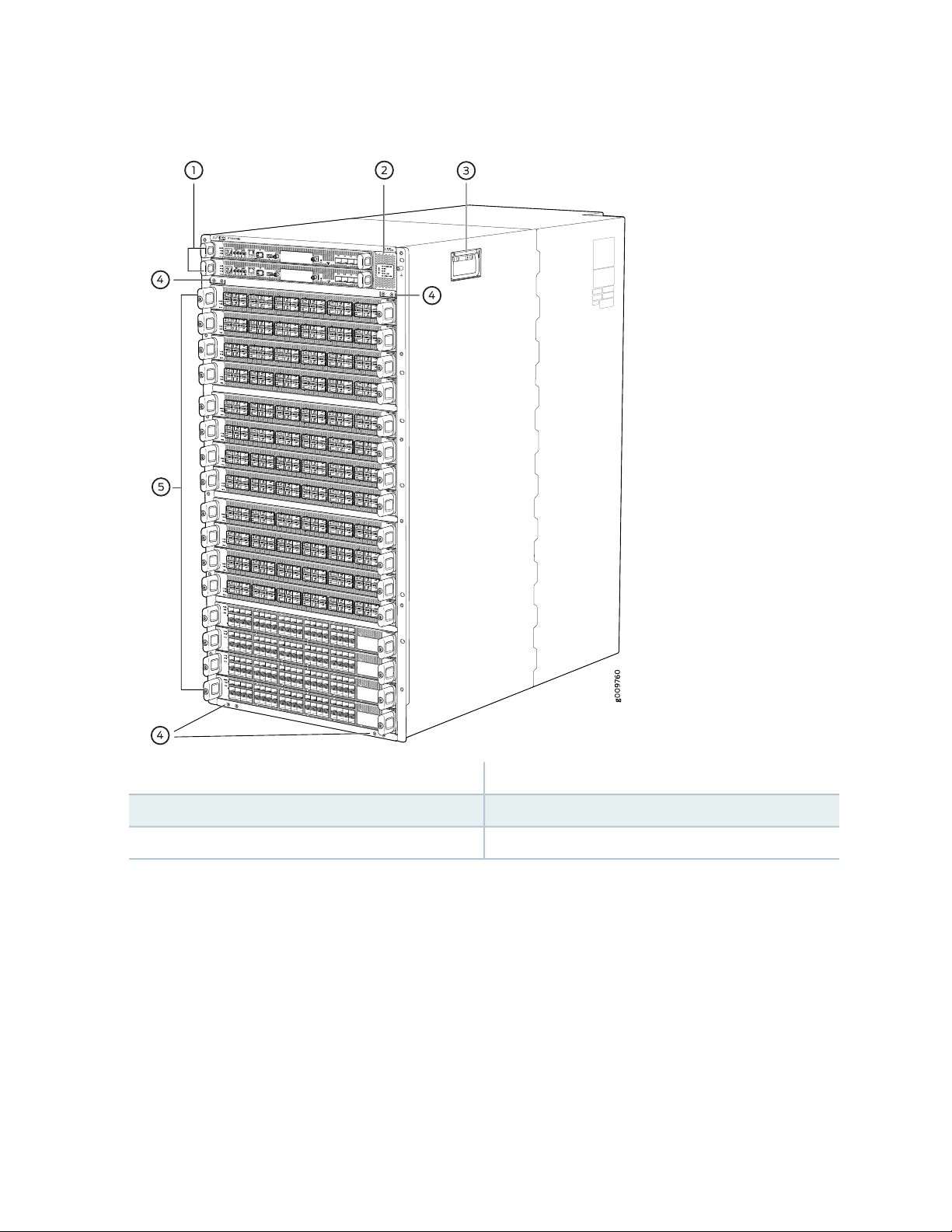
Figure 1: PTX10016 Chassis Front
23
4—1— Installation holes for the front panelRouting and Control Boards
5—2— Line card slots 0-15 (numbered top to bottom)Status LED panel
3—Handle
Some chassis ship with an enhanced power bus to support future-proof the chassis beyond the current
generation of line cards. You can determine which chassis you have by markings on the status panel, (see
“PTX10016 Status Panel” on page 38).
Page 24
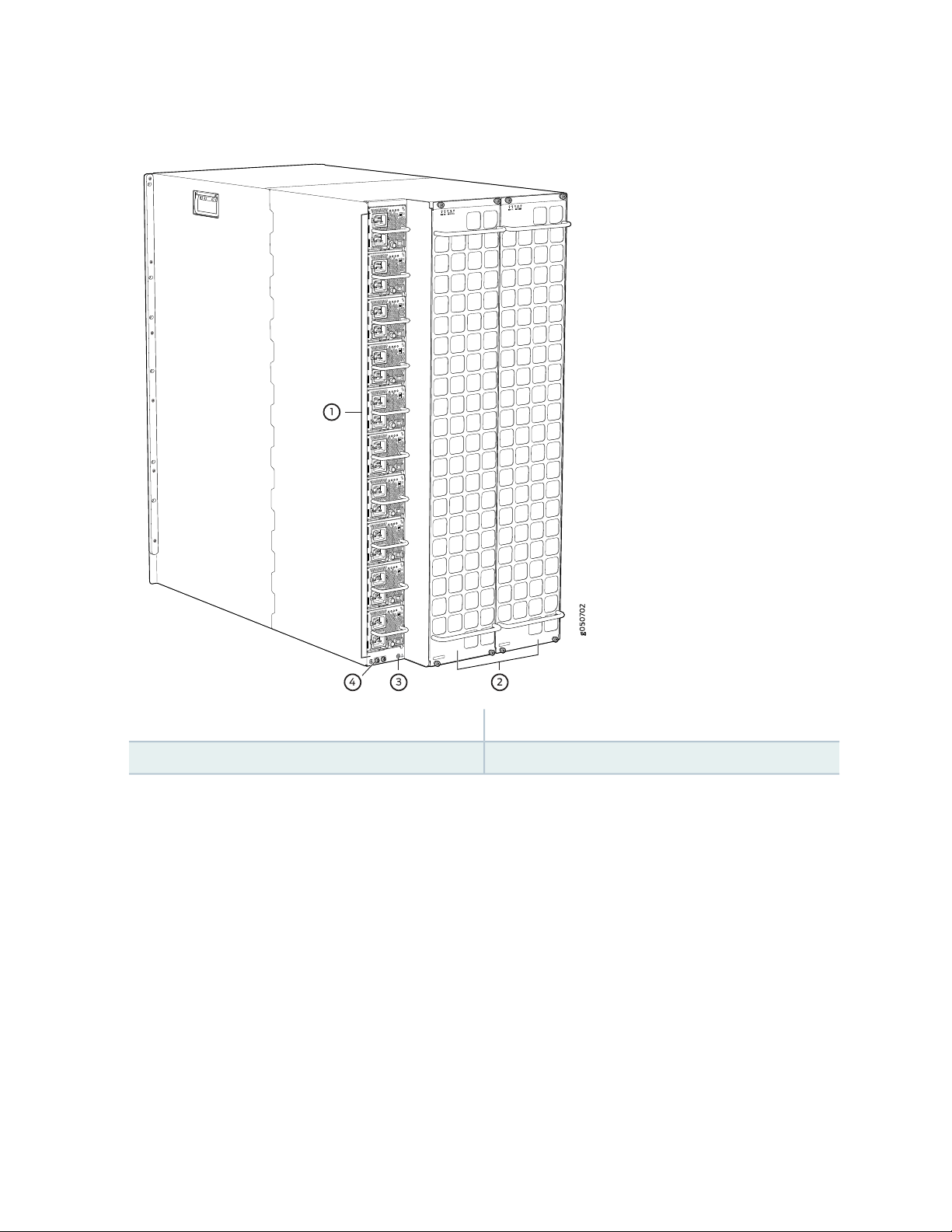
Figure 2: PTX10016 Chassis Rear
24
3—1— ESD pointAC or DC power supplies
4—2— Protective earthing terminalFan trays with redundant fans
Page 25
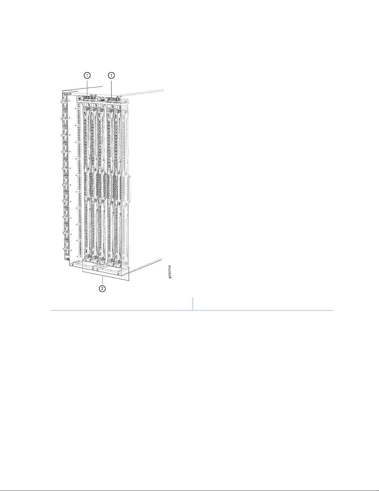
Figure 3: PTX10016 Chassis Internal Components
25
2—1— Switch Interface Boards (SIBs)Fan tray controllers
See “PTX10016 Chassis Physical Specifications” on page 145 and “PTX10016 Field-Replaceable Units” on
page 37.
Routing and Control Board
The Routing and Control Board (RCB) (see Figure 4 on page 26) contains a Routing Engine and is responsible
for the system management and system control in the PTX10016. See “PTX10016 Routing and Control
Board Description” on page 74. RCBs are FRUs that are installed in the front of the chassis in the slots
labeled CB0 and CB1. The base configuration has a single RCB. The fully redundant configuration has two
RCBs. RCB contains Precision Time Protocol (PTP) ports and four Media Access Control Security (MACsec)
capable ports. See “PTX10016 Components and Configurations” on page 32.
Page 26

Figure 4: PTX10016 Routing and Control Board
The supported models of RCB are:
JNP10K-RE0
•
JNP10K-RE1
•
JNP10K-RE1-LT
•
JNP10K-RE1-128G
•
Line Cards
26
The PTX10016 features 16 horizontal line card slots and supports line rate for each line card. The line
cards combine a Packet Forwarding Engine and Ethernet interfaces enclosed in a single assembly. The line
card architecture for PTX10016 routers is based on a number of identical, independent PFE slices, each
with 500-Gbps full-duplex throughput. Line cards are FRUs that can be installed in the line card slots
labeled 0 through 15 (top to bottom) on the front of the router chassis. All line cards are hot-removable
and hot-insertable.
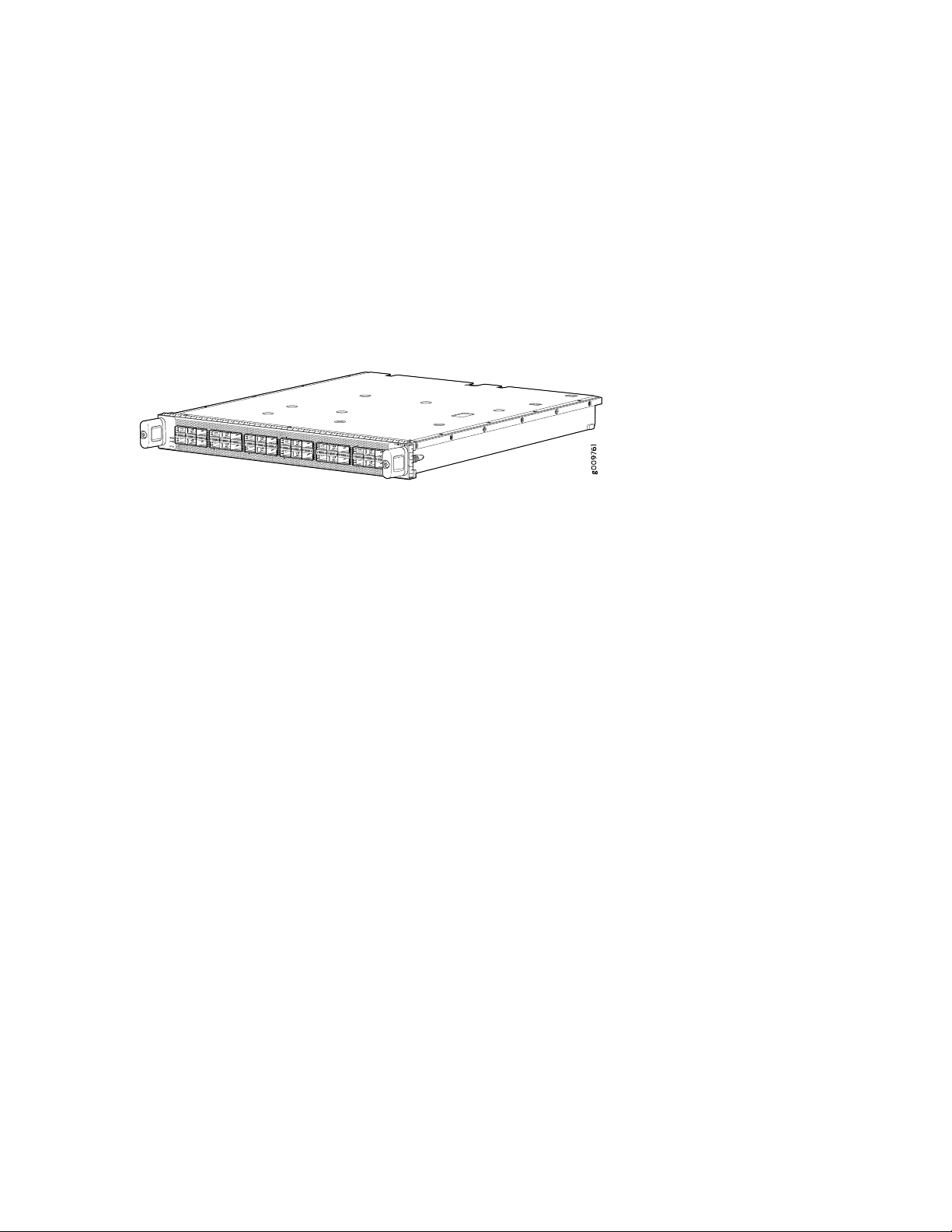
The PTX10016 supports the following line card models:
PTX10K-LC1101, a 30-port 100-Gigabit or 40-Gigabit Ethernet quad small form-factor 28 (QSFP28)
•
line card. By default, the interfaces are created with 100-Gbps port speed. Using the CLI, you can set
the speed to 40-Gbps that can be used as either a native 40-gigabit interface or four independent
10-gigabit interfaces using a breakout cable. With breakout cables, the line card supports a maximum
of 96 logical 10-Gigabit Ethernet interfaces.
PTX10K-LC1102, a 36-port 40-Gigabit Ethernet line card that supports quad small form-factor plus
•
(QSFP+) transceivers. Twelve out of the 36 ports on this line card also support the 100-Gigabit Ethernet
QSFP28 transceivers. You can configure each of the QSFP+ ports as either a native 40-Gigabit Ethernet
interface or channelize the port as four 10-Gigabit Ethernet interfaces by using a breakout cable. When
the 40 Gigabit Ethernet port is channelized, the line card supports a maximum of 144 logical 10-Gigabit
Ethernet ports.
Page 27
PTX10K-LC1104, a 6-port coherent dense wavelength-division multiplexing (DWDM) line card with
•
Media Access Control Security (MACsec). The line card features built-in optics that support flexible rate
modulation at 100-Gbps, 150-Gbps, and 200-Gbps speeds.
PTX10K-LC1105, a 30-port flexible configuration line card that supports QSFP+, QSFP28, QSFP28-DD,
•
QSFP56, and QSFP-DD transceivers. You can configure either as 100-Gigabit Ethernet interfaces or
as40-Gigabit Ethernet interfaces. The PTX10K-LC1105 line card supports MACsec security features.
See Figure 5 on page 27 for an example of a PTX10016 line card.
Figure 5: PTX10K-LC1101 Line Card
27
Switch Interface Boards
Five Switch Interface Boards (SIBs) provide the necessary switch fabric to a base configuration PTX10016
(see Figure 6 on page 28). A sixth SIB is available in the redundant configuration to provide n+1 redundancy.
SIBs are installed between the line cards and the fan trays inside the chassis. Each PTX10016 SIB has 16
connectors that match to a line card slot, eliminating the need for a backplane. When all six SIBs are
installed, the PTX10016 has a net switching capacity of 96 Tbps. See “PTX10016 Switch Interface Board
Description” on page 82.
Page 28
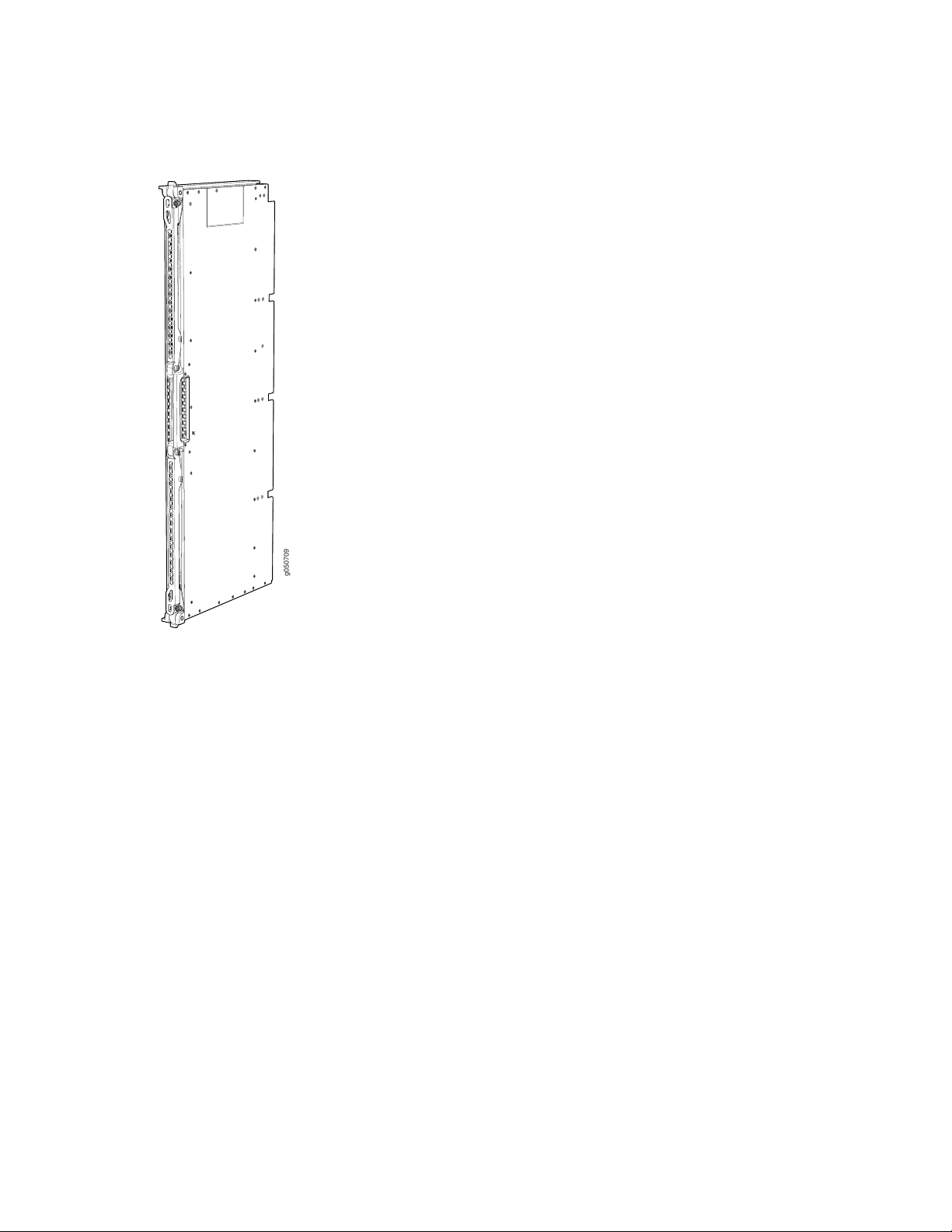
Figure 6: PTX10016 SIB
g050709
28
Cooling System
The cooling system in a PTX10016 consists of two hot-removable and hot-insertable FRU fan trays (see
Figure 7 on page 29) and two fan tray controllers (see Figure 8 on page 29). Each fan tray contains 21
fans. The fan trays install vertically on the rear of the chassis and provide front-to-back chassis cooling.
See “PTX10016 Cooling System and Airflow” on page 43.
Page 29
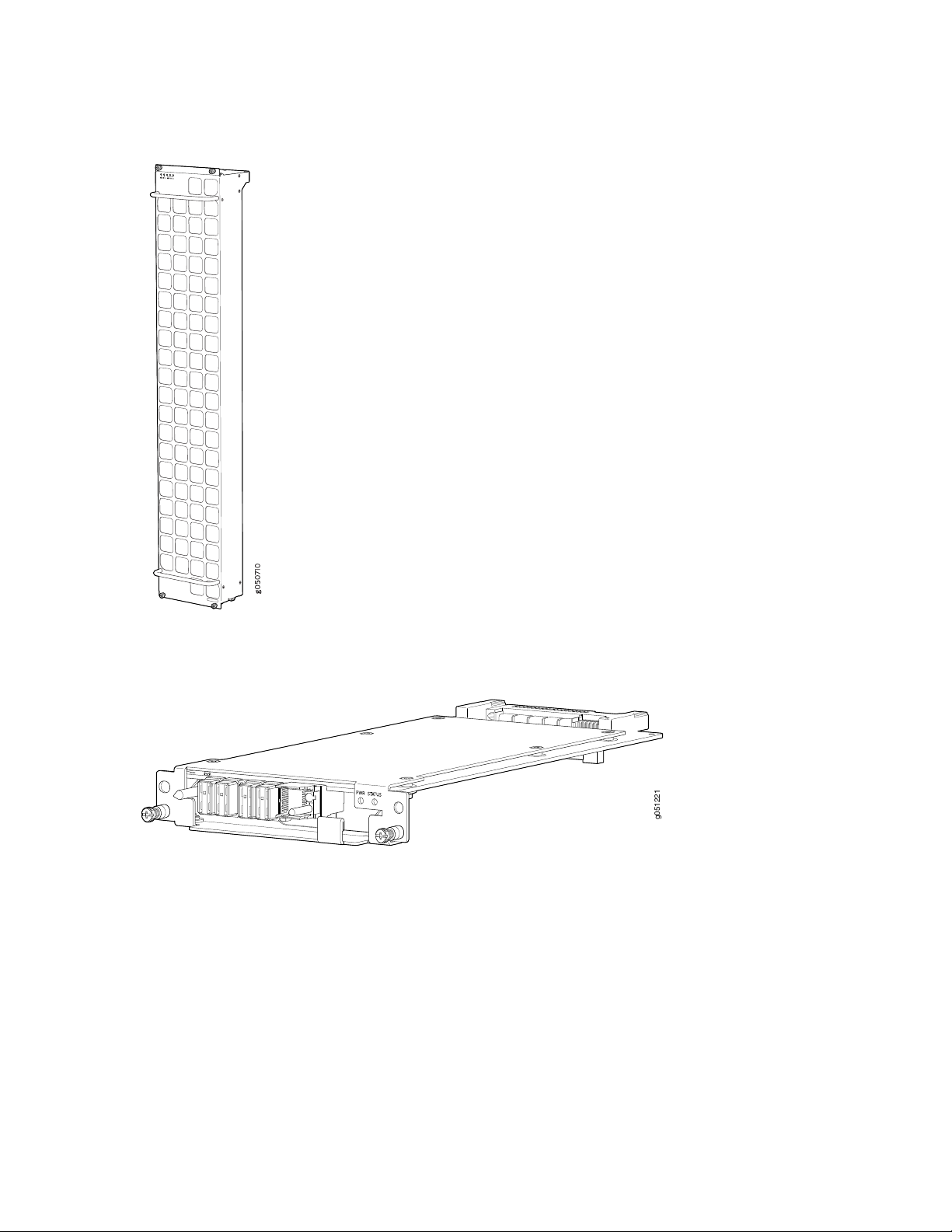
Figure 7: Fan Tray JNP10016-FAN
g051221
29
Figure 8: Fan Tray Controller JNP10016-FAN-CTRL
Power Supplies
PTX10016 routers support AC, DC, high-voltage alternating current (HVAC) and high-voltage direct current
(HVDC) by offering the following power supplies:
JNP10K-PWR-AC
•
JNP10K-PWR-AC2
•
JNP10K–PWR-DC
•
JNP10K-PWR-DC2
•
Page 30
Power supplies for the PTX10016 router are fully redundant, load-sharing, and hot-removable and
hot-insertable FRUs Each PTX10016 base configuration has five power supplies; redundant configurations
hold the maximum of ten AC, HVAC, DC, or HVDC power supplies. Each power supply has an internal fan
for cooling. You can install the power supplies in any slot. See Table 4 on page 30 and Figure 9 on page 30
through Figure 12 on page 31.
Table 4 on page 30 provides an overview of the differences among the power supplies.
Table 4: Power Supply Overview
Minimum Junos OS
ReleaseWattageInput TypePower Supply Model
Junos OS 17.4R12700 WAC onlyJNP10K-PWR AC
30
AC, HVAC, or HVDCJNP10K-PWR-AC2
DC onlyJNP10K-PWR-DC2
CAUTION: Do not mix power supply models in the same chassis in a running
environment. DC and HVDC power supplies can coexist in the same chassis when you
hot swap of DC for an HVDC model. The system provides 2n source redundancy and
n+1 power supply redundancy. If one power source fails, the power supply switches
to the alternate source.
Figure 9: JNP10K-PWR-AC Power Supply
Junos OS 18.2R15000 W, single feed; 5500 W,
dual feed
Junos OS 17.4R12500 WDC onlyJNP10K-PWR DC
Junos OS 18.2R12750 W, single feed; 5500 W,
dual feed
Page 31

Figure 10: JNP10K-PWR-AC2 Power Supply
g100585
g050571
g100595
Figure 11: JNP10K-PWR-DC Power Supply
31
Figure 12: JNP10K-PWR-DC2 Power Supply
Page 32

Software
The Juniper Networks PTX10016 line of Packet Transport Routers run Junos OS, which provides Layer 3
routing services. The same Junos OS code base that runs on the PTX10016 line of routers also runs on all
Juniper Networks EX Series Ethernet Switches, M Series Multiservice Edge Routers, MX Series 5G universal
Routing Platforms, and SRX Series Services Gateways.
PTX10016 Components and Configurations
Table 5 on page 32 lists the four hardware configurations for a PTX10016 modular chassis—base (AC
version), and redundant (AC and DC versions)—and the components included in each configuration.
Table 5: PTX10016 Hardware Configurations
Configuration ComponentsRouter Configuration
32
Base AC configuration
PTX10016-BASE
Base DC configuration
PTX10016-BASE
Chassis
•
One Routing and Control Board (RCB)
•
Two fan tray controllers (JNP10016-FAN-CTRL or JNP10016-FTC2)
•
Two fan trays (JNP10016-FAN and JNP10016-FAN2)
•
Five AC power supplies (JNP10K-PWR-AC or JNP10K-PWR-AC2)
•
Five power supply cover panels
•
Five Switch Interface Boards (SIBs)
•
One SIB cover panel
•
Sixteen line card cover panels
•
Chassis
•
One RCB
•
Two fan tray controllers (JNP10016-FAN-CTRL or JNP10016-FTC2)
•
Two fan trays (JNP10016-FAN and JNP10016-FAN2)
•
Five DC power supplies (JNP10K-PWR-DC, JNP10K-PWR-DC2, or
•
JNP10K-PWR-AC2)
Five power supply covers
•
Five SIBs
•
One SIB cover
•
Sixteen line card covers
•
Page 33

Table 5: PTX10016 Hardware Configurations (continued)
Configuration ComponentsRouter Configuration
33
Redundant AC configuration
PTX10016-PREMIUM
Redundant DC configuration
PTX10016-PREMIUM
Chassis
•
Two RCBs
•
Two fan tray controllers (JNP10016-FAN-CTRL or JNP10016-FTC2)
•
Two fan trays (JNP10016-FAN and JNP10016-FAN2)
•
Ten AC power supplies (JNP10K-PWR-AC or JNP10K-PWR-AC2)
•
Six SIBs
•
Sixteen line card covers
•
Chassis
•
Two RCBs
•
Two fan tray controllers (JNP10016-FAN-CTRL or JNP10016-FTC2)
•
Two fan trays (JNP10016-FAN and JNP10016-FAN2)
•
Ten DC power supplies (JNP10K-PWR-DC, JNP10K-PWR-DC2, or
•
JNP10K-PWR-AC2)
Six SIBs
•
Sixteen line card covers
•
NOTE: You can install up to 16 line cards (any combination of line cards) in the PTX10016.
NOTE: Line cards and the cable management system are not part of the base or redundant
configurations. You must order them separately.
NOTE: If you want to purchase additional power supplies (AC, DC, or HVAC or HVDC), SIBs, or
RCBs for your router configuration, you must order them separately.
Page 34

PTX10016 Component Redundancy
The PTX10016 router is designed so that no single point of failure can cause the entire system to fail. The
following major hardware components in the redundant configuration provide redundancy:
Routing and Control Board (RCB)—RCB consolidates the Routing Engine function with control plane
•
function in a single unit. The PTX10016 routers can have one or two RCBs. When two RCBs are installed,
one functions as the primary and the other functions as the backup. If the primary RCB (or either of its
components) fails, the backup can take over as the primary. See “PTX10016 Routing and Control Board
Description” on page 74.
Switch Interface Boards (SIBs)—The PTX10016 routers have six SIB slots. Five SIBs are required for base
•
operation and the sixth SIB provides n+1 redundancy. All six SIBs are active and can sustain full throughput
rate. The fabric plane can tolerate one SIB failure without any loss of performance. See the “PTX10016
Switch Interface Board Description” on page 82.
Power supplies—The PTX10016 routers require three power supplies for minimum operation (two RCBs,
•
two fan trays, six SIBs and no line cards). Additional power supplies provide n+1 redundancy for the
system. AC, DC, HVAC, and HVDC systems tolerate a single power supply to fail without system
interruption. If one power supply fails in a fully redundant system, the other power supplies can provide
full power to the PTX10016 indefinitely.
34
The PTX10016 routers also support power source redundancy. Two sets of lugs are provided for the
JNP10K-PWR-AC cables, four sets of lugs are provided for the JNP10K-PWR-DC2 cables, and two AC
power cords are provided for each JNP10K-PWR-AC power supply.
Cooling system—The fan trays have redundant fans, which are controlled by the fan tray controller. If
•
one of the fans fails, the host subsystem increases the speed of the remaining fans to provide sufficient
cooling for the router indefinitely. See “PTX10016 Cooling System and Airflow” on page 43.
PTX10016 Hardware and CLI Terminology Mapping
This topic describes the hardware terms used in PTX10016 router documentation and the corresponding
terms used in the Junos OS CLI. See Table 6 on page 34.
Table 6: CLI Equivalents of Terms Used in Documentation for PTX10016 Routers
Hardware
Item (CLI)
Item In
DocumentationValue (CLI)Description (CLI)
Router chassis–PTX10016Chassis
Additional Information
“PTX10016 Chassis Physical
Specifications” on page 145
Page 35

Table 6: CLI Equivalents of Terms Used in Documentation for PTX10016 Routers (continued)
35
Hardware
Item (CLI)
Fan tray
FPC (n)
JNP10016-FAN or
JNP10016-FAN2
Abbreviated name of
the Flexible PIC
Concentrator (FPC)
On PTX10016, an
FPC is equivalent to
a line card.
n is a value in the range
of 0–10 for the
JNP10016-FAN, or
JNP10016-FAN2. The
value corresponds to the
individual fan number in
the fan tray.
n is a value in the range
of 0–15 for the
PTX10016. The value
corresponds to the
line-card slot number in
which the line card is
installed.
Item In
DocumentationValue (CLI)Description (CLI)
Fan trayFan Tray 0|1 Fan n
Line card (The
router does
not have actual
FPCs—the line
cards are the
FPC
equivalents on
the router.)
Additional Information
“PTX10016 Cooling System and
Airflow” on page 43
Understanding Interface Naming
Conventions
PSM (n)
Abbreviation for
power supply
module
One of the
following:
JNP10K-PWR-AC
•
JNP10K-PWR-AC2
•
JNP10K-PWR-DC
•
JNP10K-PWR-DC2
•
RE (n)RE
n is a value in the range
of 0–5. The value
corresponds to the
power-supply slot
number.
of 0–1.
Multiple line items
appear in the CLI if more
than one RCB is installed
in the chassis.
–Value of n is always 0.–PIC (n)
AC, DC,
HVAC, or
HVDC power
supply
RCBn is a value in the range
Understanding Interface Naming
Conventions
One of the following:
JNP10K-PWR-AC Power
•
Supply on page 57
JNP10K-PWR-AC2 Power
•
Supply on page 60
JNP10K-PWR-DC Power
•
Supply on page 62
JNP10K-PWR-DC2 Power
•
Supply on page 64
“PTX10016 Routing and Control
Board Description” on page 74
Page 36

Table 6: CLI Equivalents of Terms Used in Documentation for PTX10016 Routers (continued)
36
Hardware
Item (CLI)
SIB (n)
Xcvr (n)
This field indicates:
State of the fabric
•
plane:
Active
•
Spare
•
Check state
•
Status of the
•
Packet
Forwarding
Engine in each
fabric plane:
Links OK
•
Error
•
Abbreviated name of
the transceiver
of 0–5.
n is a value equivalent to
the number of the port
in which the transceiver
is installed.
Item In
DocumentationValue (CLI)Description (CLI)
Optical
transceivers
Additional Information
show chassis fabric sibsFabric planen is a value in the range
“PTX10016 Optical Transceiver
and Cable Support” on page 170
RELATED DOCUMENTATION
PTX10016 Cooling System | 43
Perform the Initial Configuration for the PTX10016 Router | 212
PTX10016 Routing and Control Board Description | 74
PTX10016 Power System | 56
PTX10016 Switch Interface Board Description | 82
PTX10016 Chassis
The PTX10016 chassis houses the hardware components. The chassis components include the fan trays,
fan tray controllers, power supplies, Routing and Control Boards (RCBs), line cards, optional cable
management system, and the status panel.
Page 37

PTX10016 Field-Replaceable Units
Field-replaceable units (FRUs) are router components that you can replace at your site. The router uses
the following types of FRUs:
Hot-insertable and hot-removable—You can remove and replace these components without powering
•
off the router or disrupting the routing function.
Hot-pluggable—You can remove and replace these components without powering off the router, but
•
the routing function is interrupted until you replace the component.
Table 7 on page 37 lists the FRUs and their types for the PTX10016 routers.
Table 7: FRUs in an PTX10016 Router
TypeFRU
Hot-insertable and hot-removable.Power supplies
37
Routing and Control Boards
(RCBs)
Switch Interface Boards (SIBs)
Hot-insertable and hot-removable.Fan trays
Hot-insertable and hot-removable.Fan tray controllers
Redundant configuration:
Primary RCB is hot-pluggable.
•
Backup RCB is hot-insertable and hot-removable.
•
Base configuration:
Removal of the RCB causes the router to shut down. You can install a
•
replacement RCB in the second slot. The system restarts to elect a primary RCB
and a backup RCB. If necessary, you can switch the primary and backup RCBs
using the request chassis routing-engine master switch command.
See “PTX10016 Components and Configurations” on page 32.
SIBs are hot-insertable and hot-removable. We recommend that you take SIBs
offline before removing them to avoid traffic loss while the router fabric is being
reconfigured. Use the following command:
user@router> request chassis sib slot slot-number offline
Line cards
Hot-insertable. We recommend that you take line cards offline before removing
them. Use the following command:
user@router> request chassis fpc-slot slot-number offline
Page 38

Table 7: FRUs in an PTX10016 Router (continued)
TypeFRU
Hot-insertable and hot-removable.Optical transceivers
See “PTX10016 Optical
Transceiver and Cable Support”
on page 170 for how to find
detailed specifications and the
Junos OS release in which the
transceivers were introduced.
NOTE: Line cards are not part of the base or redundant configuration. You must order them
separately.
38
NOTE: If you have a Juniper Care service contract, register any addition, change, or upgrade of
hardware components at https://www.juniper.net/customers/support/tools/updateinstallbase/.
Failure to do so can result in significant delays if you need replacement parts. This note does
not apply if you replace an existing component with the same type of component.
PTX10016 Status Panel
The status panel of the PTX10016 has two purposes:
Shows the overall status of the chassis
•
Indicates the type of power bus internal to the chassis
•
Some chassis ship with an enhanced power bus to future-proof the chassis for potential power growth.
The status panel indicates the chassis status through a set of five bicolor LEDs. See Figure 13 on page 39
for a chassis status panel with the standard power bus.
Page 39

Figure 13: Status Panel on Chassis with the Standard Power Bus
g100339
Other chassis also have the same set of five bicolor LEDs, but also have an azure blue line to indicate the
presence of the enhanced power bus (see Figure 14 on page 39).
Figure 14: Status Panel on Chassis with the Enhanced Power Bus
39
Table 8 on page 39 describes the status panel LEDs.
Table 8: Status Panel LEDs in a PTX10016
warning symbol)
warning symbol)
DescriptionStateColorName
No minor alarms are active.OffYellow! Minor alarm (Triangle
A minor alarm is active.On steadily
No major alarms are active.OffRed! Major alarm (Circle
A major alarm is active.On steadily
Page 40

Table 8: Status Panel LEDs in a PTX10016 (continued)
40
DescriptionStateColorName
On steadilyGreenPOWER SUPPLIES
BlinkingYellow
OffNone
On steadilyGreenFANS
BlinkingYellow
OffNone
On steadilyGreenSIBS
All of the power supplies are online and
operating normally.
One or more of the power supplies has an
error.
None of the power supplies is receiving
power.
The fans and the fan tray controllers are
online and operating normally.
There is an error in a fan or in one of the
fan tray controllers.
The fan tray controllers and fan trays are
not receiving power.
At least one installed Switch Interface
Board (SIB) is online.
BlinkingYellow
BlinkingYellow
On steadilyGreenCONTROL BOARDS
There is a hardware error in one or more
SIBs.
All the SIBs are offline.OffNone
At least one installed line card is online.On steadilyGreenLINE CARDS
There is a hardware error in one or more
line cards.
All the line cards are offline.OffNone
All installed Routing and Control Boards
(RCBs) are online.
One or more RCBs have an error condition.BlinkingYellow
The installed RCBs are offline.OffNone
Page 41

SEE ALSO
PTX10016 Routing and Control Board Components and Descriptions | 74
PTX10016 Cooling System and Airflow | 43
PTX10016 Switch Fabric | 81
PTX10016 Optional Equipment
IN THIS SECTION
PTX10016 Cable Management System | 41
41
The PTX10016 routers supports the cable management system (JLC-CBL-MGMT-KIT) as optional
equipment:
PTX10016 Cable Management System
You can use the PTX10016 cable management system (see Figure 15 on page 41) to route optical cables
away from the line-card ports for better airflow through the chassis. Using this optional system also makes
it easier to use cable ties or strips to organize the cabling.
Figure 15: PTX10016 Cable Management System
Page 42

The cable management system comprises a set of handle extensions and a tray that snaps to the extensions
(see Figure 16 on page 42) for an individual line card. You can use the handle extensions with or without
the cable tray. You don’t need to remove the handle extensions if you want to remove a line card.
Figure 16: Cable Management Parts
2—1— Cable trayHandle extensions
Cables are draped across or under the handle extensions and then secured with cable wraps (see
Figure 17 on page 42).
42
Figure 17: Two Cable Management Systems Installed
SEE ALSO
Install the PTX10016 Cable Management System | 293
PTX10016 Line Card Components and Descriptions | 86
Page 43

PTX10016 Cooling System
IN THIS SECTION
PTX10016 Cooling System and Airflow | 43
PTX10016 Fan Tray LEDs and Fan Tray Controller LEDs | 50
The PTX10016 cooling system components work together to keep all components within the acceptable
temperature range. If the maximum temperature specification is exceeded and the system cannot be
adequately cooled, the Routing and Control Board (RCB) shuts down some or all of the hardware
components.
43
PTX10016 Cooling System and Airflow
IN THIS SECTION
Fan Tray | 43
Fan Tray Controller | 46
Airflow Direction in the PTX10016 | 49
The cooling system in a PTX10016 chassis consists of dual fan trays and dual fan tray controllers.
Two fan tray models and their associated fan tray controllers are available. See Table 9 on page 45.
Fan Tray
All fan trays are hot-insertable and hot-removable field replaceable units (FRUs). Each fan tray contains
21 fans, a non-removable control board, and LEDs.
The two fan trays install vertically, side by side, next to the power supplies on the FRU side of the chassis.
Two handles on each front faceplate facilitate handling of the fan tray. See Figure 18 on page 44 and
Figure 19 on page 45.
Page 44

Figure 18: Fan Tray JNP10016-FAN for a PTX10016
44
Page 45

Figure 19: Fan Tray JNP10016-FAN2 for a PTX10016
g100671
45
See Table 9 on page 45 for the physical specifications for the fan trays.
Table 9: Fan Tray Specifications
model
Volume flow at 100%
130.67 CFM per fan or 2,744.07 CFM
per fan tray
JNP10016-FAN2JNP10016-FANSpecification
JNP10016-FTC2JNP10016-FAN-CTLRCorresponding fan tray controller
2121Number of fans per fan tray
4242Number of fans per chassis
163 CFM per fan or 3,423 CFM per
fan tray
19.2R1-S115.1X53-D30Introduced in Junos OS Release
36.5 in. (92.97 cm)36.6 in. (92.97 cm)Height
6.6 in. (16.8 cm)6.6 in. (16.8 cm)Width
Page 46

Table 9: Fan Tray Specifications (continued)
46
JNP10016-FAN2JNP10016-FANSpecification
Depth
4.0 in. (10.2 cm) without handles, 5.2 in.
(13.2 cm) with handles
5.5 in. (13.97 cm) without handles,
6.7 in. (17.01 cm)
33.8 lb (15.33 kg)19.8 lb (8.98 kg)Weight
Only remove one fan tray when replacing an existing fan tray while the router is running. The router
continues to operate for a limited time with a single operating fan tray without triggering a thermal alarm.
CAUTION: To avoid a thermal alarm, do not remove both fan trays while the router
is operating.
CAUTION: The chassis will shut down if a thermal alarm is raised for more than three
minutes.
The internal fan Control Board in each fan tray contains the LEDs for the associated fan tray controllers
and the LEDs for the three SIBs directly behind the fan tray.
Fan Tray Controller
The two fan tray controllers provide the control logic and power to hot-insert and hot-remove a fan tray.
The fans in each fan tray are numbered 0 through 20.
The system continually monitors the temperature of critical parts across the chassis and adjusts the chassis
fan speed according to the temperature.
There are two fan tray controller models:
JNP10016-FAN-CTRL—Supports model JNP10016-FAN; see Figure 20 on page 47.
•
Page 47

Figure 20: Fan Tray Controller JNP10016-FAN-CTRL
g051221
g100696
JNP10016-FTC2—Supports model JNP10016-FAN2; see Figure 21 on page 47.
•
Figure 21: Fan Controller JNP10016-FTC2
47
Software controls the fan speed. Under normal operating conditions, the fans in the fan tray run at less
than full speed. If one fan tray controller fails or appears missing (such as when a SIB is being replaced)
the other fan tray controller sets the fans to full speed. This allows the router to continue to operate
normally as long as the remaining fans cool the chassis sufficiently. Use the show chassis fan command
to see the status of individual fans and fan speed. For example:
user@device> show chassis fan
Item Status RPM Measurement
Fan Tray 0 Fan 0 OK 4500 Spinning at normal speed
Fan Tray 0 Fan 1 OK 4650 Spinning at normal speed
Fan Tray 0 Fan 2 OK 4650 Spinning at normal speed
Fan Tray 0 Fan 3 OK 4800 Spinning at normal speed
Fan Tray 0 Fan 4 OK 4650 Spinning at normal speed
Fan Tray 0 Fan 5 OK 4650 Spinning at normal speed
Fan Tray 0 Fan 6 OK 4650 Spinning at normal speed
Fan Tray 0 Fan 7 OK 4500 Spinning at normal speed
Fan Tray 0 Fan 8 OK 4500 Spinning at normal speed
Fan Tray 0 Fan 9 OK 4650 Spinning at normal speed
Fan Tray 0 Fan 10 OK 4650 Spinning at normal speed
Page 48

Fan Tray 0 Fan 11 OK 4500 Spinning at normal speed
Fan Tray 0 Fan 12 OK 4500 Spinning at normal speed
Fan Tray 0 Fan 13 OK 4500 Spinning at normal speed
Fan Tray 0 Fan 14 OK 4650 Spinning at normal speed
Fan Tray 0 Fan 15 OK 4350 Spinning at normal speed
Fan Tray 0 Fan 16 OK 4500 Spinning at normal speed
Fan Tray 0 Fan 17 OK 4500 Spinning at normal speed
Fan Tray 0 Fan 18 OK 4350 Spinning at normal speed
Fan Tray 0 Fan 19 OK 4500 Spinning at normal speed
Fan Tray 0 Fan 20 OK 4500 Spinning at normal speed
Fan Tray 1 Fan 0 OK 4500 Spinning at normal speed
Fan Tray 1 Fan 1 OK 4650 Spinning at normal speed
Fan Tray 1 Fan 2 OK 4500 Spinning at normal speed
Fan Tray 1 Fan 3 OK 4500 Spinning at normal speed
Fan Tray 1 Fan 4 OK 4650 Spinning at normal speed
Fan Tray 1 Fan 5 OK 4650 Spinning at normal speed
Fan Tray 1 Fan 6 OK 4650 Spinning at normal speed
Fan Tray 1 Fan 7 OK 4500 Spinning at normal speed
Fan Tray 1 Fan 8 OK 4500 Spinning at normal speed
Fan Tray 1 Fan 9 OK 4650 Spinning at normal speed
Fan Tray 1 Fan 10 OK 4500 Spinning at normal speed
Fan Tray 1 Fan 11 OK 4500 Spinning at normal speed
Fan Tray 1 Fan 12 OK 4500 Spinning at normal speed
Fan Tray 1 Fan 13 OK 4650 Spinning at normal speed
Fan Tray 1 Fan 14 OK 4500 Spinning at normal speed
Fan Tray 1 Fan 15 OK 4650 Spinning at normal speed
Fan Tray 1 Fan 16 OK 4650 Spinning at normal speed
Fan Tray 1 Fan 17 OK 4650 Spinning at normal speed
Fan Tray 1 Fan 18 OK 4650 Spinning at normal speed
Fan Tray 1 Fan 19 OK 4500 Spinning at normal speed
Fan Tray 1 Fan 20 OK 4500 Spinning at normal speed
48
user@device>
Two fan tray controller models and their associated fan trays are available. All models are hot-insertable
and hot-removable. See Table 10 on page 48.
Table 10: Fan Tray Controller Specifications
JNP10016-FTC2JNP10016-FAN-CTRLSpecification
JNP10016-FAN2JNP10016-FANCorresponding fan tray model
19.2R117.4.R1Introduced in Junos OS Release
Page 49

Table 10: Fan Tray Controller Specifications (continued)
g050722
Side view
FRUsPorts
Control boards
Linecards SIBs
Fan
trays
Fan tray controllers
Power
supplies
JNP10016-FTC2JNP10016-FAN-CTRLSpecification
1.5 in. (3.81 cm)1.5 in. (3.81 cm)Height
6.5 in. (15.24 cm)6.5 in. (15.24 cm)Width
12.4 in. (31.5 cm)12.4 in. (31.5 cm)Depth
2.3 lb (1.04 cm)1.5 lb (0.68 kg)Weight
Airflow Direction in the PTX10016
The air intake to cool the chassis is located on the port (line card) side of the chassis. Air flows into the
chassis from the ports in the RCBs and line cards, through the SIBs, and exits from the fan trays and the
power supplies. This airflow is called port-to-FRU cooling or airflow out (AFO). See Figure 22 on page 49.
49
Figure 22: Airflow Through a PTX10016
Page 50

The fan tray continues to operate indefinitely and provides sufficient cooling even when a single fan fails,
provided the room temperature is within the operating range. You can check the status of fans by viewing
the LEDs on each fan tray. See “PTX10016 Fan Tray LEDs and Fan Tray Controller LEDs” on page 50.
You cannot replace a single fan. If one or more fans fail, you must replace the entire fan tray.
In addition to the fan trays, there is an internal fan in each power supply.
PTX10016 Fan Tray LEDs and Fan Tray Controller LEDs
IN THIS SECTION
Fan Tray LEDs | 50
Fan Tray Controller LEDs | 55
50
Each fan tray has a set of LEDs, and each corresponding fan tray controller also has a set of LEDs.
Fan Tray LEDs
Each fan tray has a set of LEDs that represent the status of the fans in the fan tray, the fan tray controller,
and the three Switch Interface Boards (SIBs). The fan tray LEDs are located in the top left corner of each
fan tray. Figure 23 on page 51 shows the location of the LEDs on JNP10016-FAN fan trays. See
Figure 24 on page 51 for the location of LEDs on the JNP10016-FAN2 fan trays.
Page 51

Figure 23: Fan Tray JNP10016-FAN LEDs
g100655
31 2
51
Fan status LED
2—Fan tray controller status LED
Figure 24: Fan Tray JNP10016-FAN2 LEDs
3—1— SIB status LEDs (SIB 0 through SIB 2 for the left fan
tray and SIB 3 through SIB 5 for the right fan tray)
Fan status LED
3—1— SIB status LEDs (SIB 0 through SIB 2 for the left fan
tray and SIB 3 through SIB 5 for the right fan tray).
2—Fan tray controller status LED
Table 11 on page 52 describes the functions of the fan tray LEDs.
Page 52

Table 11: Fan Tray LEDs on a PTX10016 Router
52
DescriptionStateColorName
status)
On steadilyGreenFAN (fan status)
BlinkingYellow
OffNone
On steadilyGreenFTC (fan tray controller
BlinkingYellow
All fans are operating normally. The system
has verified that the fan tray is engaged,
that the airflow is in the correct direction,
and that all fans are operating correctly.
An error has been detected in one or more
fans in the fan tray. Replace the fan tray
as soon as possible. Either the fan has
failed or it has become disconnected.To
maintain proper airflow through the
chassis, leave the fan tray installed in the
chassis until you are ready to replace it.
The fan is not receiving power from the
fan tray controller.
The fan tray controller is online and is
operating normally.
An error has been detected in the fan tray
controller. Replace the fan tray controller
as soon as possible. The fan tray controller
is located behind the fan tray above the
SIBs. To maintain proper airflow through
the chassis, leave the fan tray installed in
the chassis until you are ready to replace
the fan tray controller.
OffNone
The fan tray controller is not receiving
power.
Page 53

Table 11: Fan Tray LEDs on a PTX10016 Router (continued)
53
DescriptionStateColorName
The left-most SIB in the chassis is online.On steadilyGreenSIB Status (SIB 0 status)
BlinkingYellow
On steadilyGreenSIB Status (SIB 1 status)
BlinkingYellow
An error has been detected in SIB 0.
Replace the SIB as soon as possible. The
SIB is located behind the left fan tray and
is the left-most SIB in the chassis. To
maintain proper airflow through the
chassis, leave the fan tray installed in the
chassis until you are ready to replace the
SIB.
The SIB is offline.OffNone
The center SIB behind the left fan tray is
online.
An error has been detected in SIB 1.
Replace the SIB as soon as possible. The
SIB is located behind the left fan tray and
is the middle SIB in the group of 3. To
maintain proper airflow through the
chassis, leave the fan tray installed in the
chassis until you are ready to replace the
SIB.
The SIB is offline.OffNone
On steadilyGreenSIB Status (SIB 2 status)
BlinkingYellow
The right-most SIB behind the left fan tray
is online.
An error has been detected in SIB 2.
Replace the SIB as soon as possible. The
SIB is located behind the left fan tray and
is the right-most SIB in the group of 3. To
maintain proper airflow through the
chassis, leave the fan tray installed in the
chassis until you are ready to replace the
SIB.
The SIB is offline.OffNone
Page 54

Table 11: Fan Tray LEDs on a PTX10016 Router (continued)
54
DescriptionStateColorName
On steadilyGreenSIB Status (SIB 3 status)
BlinkingYellow
On steadilyGreenSIB Status (SIB 4 status)
BlinkingYellow
The left-most SIB behind the right fan tray
is online.
An error has been detected in SIB 3.
Replace the SIB as soon as possible. The
SIB is located behind the right fan tray and
is the left-most SIB in the group of 3. To
maintain proper airflow through the
chassis, leave the fan tray installed in the
chassis until you are ready to replace the
SIB.
The SIB is offline.OffNone
The center SIB behind the right fan tray is
online.
An error has been detected in SIB 4.
Replace the SIB as soon as possible. The
SIB is located behind the right fan tray and
is the middle SIB in the group of 3. To
maintain proper airflow through the
chassis, leave the fan tray installed in the
chassis until you are ready to replace the
SIB.
The SIB is offline.OffNone
On steadilyGreenSIB Status (SIB 5 status)
BlinkingYellow
The right-most SIB behind the right fan
tray is online.
An error has been detected in SIB 5.
Replace the SIB as soon as possible. The
SIB is located behind the right fan tray and
is the right-most SIB in the group of 3. To
maintain proper airflow through the
chassis, leave the fan tray installed in the
chassis until you are ready to replace the
SIB.
The SIB is offline.OffNone
Page 55

Fan Tray Controller LEDs
All models of fan tray controller have the same LEDs. The fan tray controller LEDs are visible only when
the associated fan tray is removed. The fan tray controller LEDs are located on the right of the controller
panel. Figure 25 on page 55 shows the location of the LEDs on the JNP10016-FAN-CTRL or the
JNP10016-FTC2 fan tray controller faceplate.
Figure 25: Fan Tray Controller LEDs on a PTX10016
2—1— Fan tray controller statusFan tray controller power
55
Table 12 on page 55 describes the functions of the fan tray controller LEDs.
Table 12: Fan Tray Controller LEDs on a PTX10016
DescriptionStateColorName
On steadilyGreenPWR (fan tray controller
power)
BlinkingYellow
OffNone
The fan tray controller has power and is
operating normally.
A power error has been detected in the
fan tray controller. Replace the fan tray
controller as soon as possible. To maintain
proper airflow through the chassis, leave
the fan tray installed in the chassis until
you are ready to replace the fan tray
controller.
The fan tray controller is not powered on
or is not receiving power.
Page 56

Table 12: Fan Tray Controller LEDs on a PTX10016 (continued)
56
DescriptionStateColorName
status)
SEE ALSO
Install a PTX10016 Fan Tray Controller | 231
Remove a PTX10016 Fan Tray Controller | 233
On steadilyGreenSTATUS (fan tray controller
BlinkingYellow
OffNone
The fan tray controller is online and is
operating normally.
An error has been detected in the fan tray
controller. Replace the fan tray controller
as soon as possible. To maintain proper
airflow through the chassis, leave the fan
tray installed in the chassis until you are
ready to replace the fan tray controller.
The fan tray controller is not receiving
power.
RELATED DOCUMENTATION
Install a PTX10016 Fan Tray | 223
Remove a PTX10016 Fan Tray | 226
PTX10016 Power System
IN THIS SECTION
JNP10K-PWR-AC Power Supply | 57
JNP10K-PWR-AC2 Power Supply | 60
JNP10K-PWR-DC Power Supply | 62
JNP10K-PWR-DC2 Power Supply | 64
JNP10K-PWR-AC Power Supply LEDs | 66
Page 57

JNP10K-PWR-AC2 Power Supply LEDs | 68
JNP10K-PWR-DC Power Supply LEDs | 70
JNP10K-PWR-DC2 Power Supply LEDs | 72
PTX10016 routers support AC, DC, high-voltage alternating current (HVAC) and high-voltage direct current
(HVDC) by offering the following power supplies:
JNP10K-PWR-AC
•
JNP10K-PWR-AC2
•
JNP10K–PWR-DC
•
JNP10K-PWR-DC2
•
You can install up to 10 power supplies in the slots labeled PEM 0 through PEM 9 (top to bottom) located
in the rear of the chassis.
57
JNP10K-PWR-AC Power Supply
The JNP10K-PWR-AC power supplies are 2700-W and support 200–240 VAC. The output power is
2700 W.
CAUTION: Do not mix AC and DC power supplies in the same chassis. AC and HVAC
can coexist in the same chassis during the hot swap of AC for HVAC. Do not mix AC
and HVAC power supplies in a running environment.
WARNING: The router is pluggable type A equipment installed in a restricted-access
location. It has a separate protective earthing terminal on the chassis that must be
connected to earth ground permanently to ground the chassis adequately and protect
the operator from electrical hazards.
Page 58

CAUTION: Before you begin installing the router, ensure that a licensed electrician
has attached an appropriate grounding lug to the grounding cable that you supply.
Using a grounding cable with an incorrectly attached lug can damage the router.
CAUTION: You can prevent AC power cables from being exposed to hot air exhaust
by always routing the power cables away from the fan trays and power supplies.
The number of power supplies furnished as standard varies by configuration model. For details about
different router configurations, see “PTX10016 Components and Configurations” on page 32.
Each JNP10K-PWR-AC power supply has two independent 16-A rated AC inlets on the faceplate. Although
each inlet provides sufficient input power to provide full output, always connect to a dedicated AC power
feed to provide redundancy. Only one power feed is operational at a time. The JNP10K-PWR-AC does
not share power; all power comes into INP1 (lower receptacle) and only uses INP2 (top receptacle) at fail
over.
58
NOTE: For redundancy, always plug the two power cords from each power supply:
INP1 into the public electricity supply
•
INP2 into an alternative or independent power source
•
Each JNP10K-PWR-AC power supply has a power switch with international markings for on (|) and off
(O), a fan, and four LEDs on the faceplate that indicate the status of the power supply. It also has a set of
dual inline package (DIP) switches that enable the source feeds, INP1 and INP2. See Figure 26 on page 58.
Figure 26: JNP10K-PWR-AC Power Supply
Page 59

Each JNP10K-PWR-AC power supply comes with two power cord retainers that hold the power cords in
ON
FAULT
PWROK
INP2
INP1
1
2
g050637
place. See Figure 27 on page 59. Each power cord retainer has a clip and an adjustment nut. The ends of
the clip hook into the bracket holes on each side of the AC appliance inlet on the faceplate. The adjustment
nut holds the power cord in the correct position. For instructions on installing the power cord retainers,
see “Connect AC Power to the PTX10016 Router” on page 208.
NOTE: Route all the AC power supply cords away from the fan trays. Make sure that the power
cords do not obstruct the fan trays.
Figure 27: Power Cord Retainer for an JNP10K-PWR-AC Power Supply
59
Each power supply connects to the power rail in the router. The power rail distributes the output power
produced by the power supplies to different router components. Each power supply provides power to
all the components in the router.
Each power supply has its own fan and is cooled by its own internal cooling system. Hot air exhausts from
the rear of the chassis.
SEE ALSO
JNP10K-PWR-AC Power Specifications | 156
Install a JNP10K-PWR-AC Power Supply | 237
Remove a JNP10K-PWR-AC Power Supply | 242
Page 60

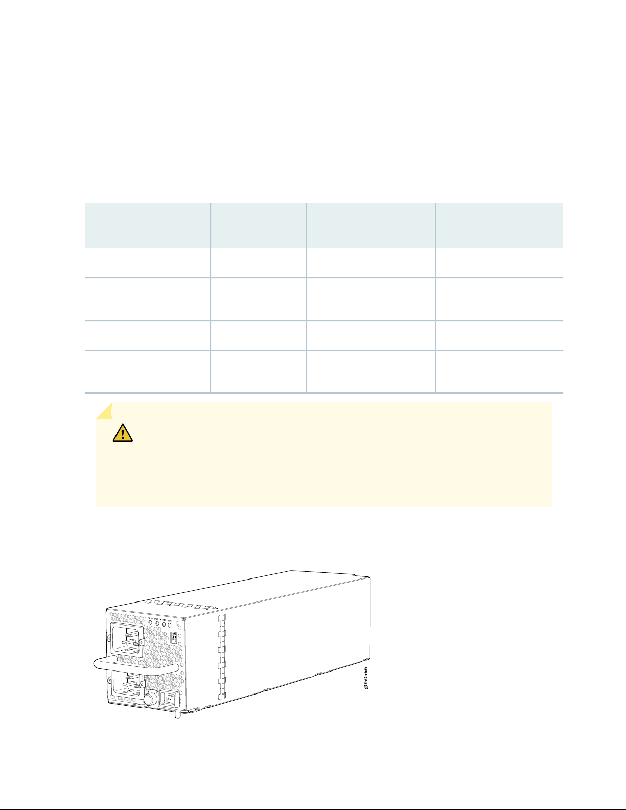
JNP10K-PWR-AC2 Power Supply
g100586
JNP10K-PWR-AC2 JNP-PWR-AC
The JNP10K-PWR-AC2 power supply is a high-capacity model that is designed to support AC, high voltage
AC (HVAC), or high voltage DC (HVDC) systems in either a 20-A or a 30-A mode. The power supply feeds
AC input and provides DC output 5000 W with a single feed and 5500 W with a dual feed. For AC systems,
the operating input voltage is 180 to 305 VAC and for DC systems, the operating input voltage is 190 to
410 VDC.
The number of power feeds and whether the power supplies provide high output (30-A) or low output
(20-A) power is configured using a set of dual inline package (DIP) switches on the faceplate of the power
supply. If one power supply in the chassis is set to low power, the power budget for the chassis is reduced
to low power, regardless of their DIP switch settings or the output results in CLI. This design safeguards
against accidentally setting the power supply to 30-A in a facility that can only provide 20-A and tripping
the facility circuit breaker. We recommend that you do not mix DIP switch settings in your system. See
Table 13 on page 61 for information about the input and output voltages when you use the DIP switches.
The JNP10K-PWR-AC2 fits into the standard power supply bay but when compared to the
JNP10K-PWR-AC, the JNP10K-PWR-AC2 is longer and protrudes from the bay when fully inserted into
the chassis. See Figure 28 on page 60 to see the differences in power supply length.
60
Figure 28: Comparison Between the JNP10K-PWR-AC2 and the JNP10K-PWR-AC Power Supplies
All models of power supplies running in PTX10016 routers have internal fans that contribute to chassis
cooling. However, the JNP10K-PWR-AC2 and JNP10K-PWR-DC2 power supplies play a more substantial
role in cooling the chassis than the JNP10K-PWR-AC and JNP10K-PWR-DC models. Consequently, all
six JNP10K-PWR-AC2 or JNP10K-PWR-DC2 power supplies must be present in a running chassis to have
the adequate airflow.
Page 61

WARNING: Extreme burn danger—Do not handle an HVAC or HVDC power supply
running in the chassis without heat protective gloves, such as welder’s gloves. The
JNP10K-PWR-AC2 can reach temperatures between 158°F to 176°F (70°C to 80°C)
under running conditions.
WARNING: The router is pluggable type A equipment installed in a restricted-access
location. It has a separate protective earthing terminal on the chassis that must be
connected to earth ground permanently to ground the chassis adequately and protect
the operator from electrical hazards.
CAUTION: Before you begin installing the router, ensure that a licensed electrician
has attached an appropriate grounding lug to the grounding cable that you supply.
Using a grounding cable with an incorrectly attached lug can damage the router.
61
CAUTION: Use a 2-pole circuit breaker rated at 25 A in the building installation and
the system, or as per local electrical code.
Table 13: Power Input and Output Voltages for JNP10K-PWR-AC2 Power Supplies
H/L (High Input 30 A/Low Input
20 A)INP1 (Switch 2)INP0 (Switch 1)
Output Power
5500 WOn (30 A)OnOn
3000 WOff (20 A)OnOn
5000 WOn (30 A)OffOn
5000 WOn (30 A)OnOff
2700 WOff (20 A)OffOn
2700 WOff (20 A)OnOff
Page 62

CAUTION: It is important to connect both input feeds of the JNP10K-PWR-AC2
power supply to AC mains before loading the system with power.
JNP10K-PWR-DC Power Supply
The DC power supply, JNP10K-PWR-DC, is a 2500-W, dual input power supply. The output power is
2500 W.
WARNING: The router is pluggable type A equipment installed in a restricted-access
location. It has a separate protective earthing terminal on the chassis that must be
connected to earth ground permanently to ground the chassis adequately and protect
the operator from electrical hazards.
62
CAUTION: Before you begin installing the router, ensure that a licensed electrician
has attached an appropriate grounding lug to the grounding cable that you supply.
Using a grounding cable with an incorrectly attached lug can damage the router.
NOTE: DC power supplies are shipped only in the redundant configuration of PTX10016 routers.
For details about different chassis configurations, see “PTX10016 Components and
Configurations” on page 32.
Each JNP10K-PWR-DC power supply has two independent pairs of DC input lugs (Input 1, RTN, –48V/–60V
and Input 2, RTN, –48V/–60V) on the faceplate of the power supply. Each inlet requires a dedicated DC
power feed. Although each inlet provides sufficient input power to provide full output, always connect
the power supply to a dedicated DC power feed to provide redundancy. Only one power feed is operational
at a time.
DC power models employ electronic A-B input selection. Should one power source fail, electronic A-B
input selection routes the power supply to the alternate source. The power supply internally balances
power between source input A and source input B. The default is to balance 50% to each input.
Page 63

Each JNP10K-PWR-DC power supply has a power switch with international markings for on (|) and off
(O), a built-in fan, and four LEDs on the faceplate that indicate the status of the power supply. See
Figure 29 on page 63.
Figure 29: JNP10K-PWR-DC Power Supply
63
NOTE: The JNP10K-PWR-DC power supply requires a dedicated circuit breaker for each input
DC feed. The chosen breaker should be sized to deliver 60 A of input current.
Each power supply connects to the combined power rail in a PTX10016 router. The power rail distributes
the output power produced by the power supplies to different router components. Each DC power supply
provides power to all the components in the router.
NOTE: Route all the DC power supply cords away from the fan trays. Make sure that the power
cords do not obstruct the fan trays.
A JNP10K-PWR-DC power supply can operate with only one input DC feed connected.
Each JNP10K-PWR-DC power supply has its own fan and is cooled by its own internal cooling system.
The airflow is from the front of the power supply to the back. Hot air exhausts from the rear of the chassis.
Page 64

SEE ALSO
JNP10K-PWR-DC Power Specifications | 167
Install a JNP10K-PWR-DC Power Supply | 252
Remove a JNP10K-PWR-DC Power Supply | 261
JNP10K-PWR-DC2 Power Supply
The JNP10K-PWR-DC2 power supply provides two power supplies in a single housing that accepts either
60 A or 80 A using four redundant input power feeds. The two internal power supplies (PS_0 and PS_1)
each have redundant input feeds: A0 and/or B0 for PS_0 and A1 and/or B1 for PS_1. You configure the
input using a set of three DIP switches on the power supply faceplate that sets the combined output power
for both internal power supplies. The output depends on the settings of these dip switches. See
Table 14 on page 64 and Figure 30 on page 65.
64
Table 14: Power Input and Output Voltages for JNP10K-PWR-DC2 Power Supplies
H/L
INP0
(Switch 1)
INP1
(Switch 2)
(High Input 80 A/
Low Input 60 A)
Output Power
5500 WOn (80 A)OnOn
4400 WOff (60 A)OnOn
2750 WOn (80 A)OffOn
2750 WOn (80 A)OnOff
2200 WOff (60 A)OffOn
2200 WOff (60 A)OnOff
Page 65

Figure 30: JNP10K-PWR-DC2 Power Supply
g100595
g100603
The JNP10K-PWR-DC2 fits into the standard power supply bay but when compared to the
JNP10K-PWR-DC, the JNP10K-PWR-DC2 is longer and protrudes from the bay when fully inserted into
the chassis. See Figure 31 on page 65 to see the differences in power supply length.
65
Figure 31: Comparison Between the JNP10K-PWR-DC2 and JNP10K-PWR-DC Power Supplies
All models of power supplies running in PTX10016 routers have internal fans that contribute to chassis
cooling. However, the JNP10K-PWR-AC2 and JNP10K-PWR-DC2 power supplies play a more substantial
role in cooling the chassis the JNP10K-PWR-AC and JNP10K-PWR-DC models. Consequently, all six
JNP10K-PWR-AC2 or JNP10K-PWR-DC2 power supplies must be present in a running chassis to have
the adequate airflow.
Page 66

CAUTION: Do not mix power supply models in the same chassis in a running
environment. JNP10K-PWR-DC and JNP10K-PWR-DC2 can coexist in the same
chassis during power supply upgrades.
WARNING: The router is pluggable type A equipment installed in a restricted-access
location. It has a separate protective earthing terminal on the chassis that must be
connected to earth ground permanently to ground the chassis adequately and protect
the operator from electrical hazards.
CAUTION: Before you begin installing the router, ensure that a licensed electrician
has attached an appropriate grounding lug to the grounding cable that you supply.
Using a grounding cable with an incorrectly attached lug can damage the router.
66
JNP10K-PWR-AC Power Supply LEDs
The JNP10K-PWR-AC power supply has four LEDs on its faceplate: INP1, INP2, PWR OK, and FAULT.
These LEDs display information about the status of the power supply. See Figure 32 on page 67.
Page 67

Figure 32: LEDs on an JNP10K-PWR-AC Power Supply
g050570
1 2 3 4
3—1— INP2–Source input 1FAULT
67
4—2— INP1–Source input 0PWR OK
Table 15 on page 67 describes the LEDs on a JNP10K-PWR-AC power supply.
Table 15: LEDs on a JNP10K-PWR-AC Power Supply
DescriptionStateColorLED
INP1 (INP0 in CLI output)
or INP2 (INP1 in CLI
output)
SolidRed
The power supply is functioning properly.SolidGreen
The power supply has detected a power input fault.BlinkingYellow
The power supply is switched off.UnlitNone
The power supply is functioning properly.SolidGreenPWR OK
The power supply has detected a power output fault.BlinkingYellow
The power supply is functioning properly.UnlitNoneFAULT
The power supply has failed and must be replaced.
Or, only one input is powered and the enabled router
for the input that is not powered is set to ON. See
Install a JNP10K-PWR-AC Power Supply for more
information about the enable switches.
Page 68

NOTE: If the INP1 or INP2 LED and the PWR OK LED are unlit, the AC power cable is not
g100588
1 2 3 4
installed properly or the power supply has failed.
If the INP1 or INP2 LED is lit and the PWR OK LED is unlit, the AC power supply is not installed
properly or the power supply has an internal failure.
JNP10K-PWR-AC2 Power Supply LEDs
The JNP10K-PWR-AC2 power supply has four LEDs on its faceplate: !, OK, 2, and 1. These LEDs display
information about the status of the power supply. See Figure 33 on page 68.
Figure 33: LEDs on a JNP10K-PWR-AC2 HVAC /HVDC Power Supply
68
3—1— 2 INP2–Source input 1! Fault
4—2— 1 INP1–Source input 0OK Power OK
NOTE: Physical markings on the power supply are 1 and 2. These markings correspond to INP0
and INP1 in the show chassis power output (see Table 16 on page 69 and “show chassis power”
on page 69).
show chassis power
Page 69

user@chassis> show chassis power
Chassis Power Voltage(V) Power(W)
Total Input Power 5592
PSM 0
PS0 51 960
A0 52
B0 51
PS1 51 960
A1 51
B1 52
Output 12.53 1774.98 ( 80A at 12V)
PSM 1
PS0 51 888
A0 52
B0 52
PS1 0 0
Output 12.49 879.22 ( 80A at 12V)
69
Table 16: Physical Markings on Chassis Versus show chassis power Command
show chassis power CommandPhysical Marking on JNP10K-PWR-AC2
PS0INP1
PS1INP2
Table 17 on page 69 describes the LEDs on a JNP10K-PWR-AC2 power supply.
Table 17: Interpreting JNP10K-PWR-AC2 LEDs
DescriptionStateColorLED
The input voltage is present, but a fault is detected.BlinkingYellow1 or (INPO in CLI output)
The power supply is functioning properly.SolidGreen
The power supply is switched off; voltage is zero.OffUnlit
Page 70

Table 17: Interpreting JNP10K-PWR-AC2 LEDs (continued)
70
DescriptionStateColorLED
The input voltage is present, but a fault is detected.BlinkingYellow2 or (INP1 in CLI output)
The power supply is functioning properly.SolidGreen
The power supply is switched off; voltage is zero.OffUnlit
The power supply is functioning properly.SolidGreenOK (Power OK)
The power supply output has detected a fault.BlinkingYellow
The power supply has failed and must be replaced.SolidRed! (Fault)
The power supply is functioning normally.OffUnlit
JNP10K-PWR-DC Power Supply LEDs
The JNP10K-PWR-DC power supply has four LEDs on its faceplate: INP1, INP2, PWR OK, and FAULT.
These LEDs display information about the status of the power supply. See Figure 34 on page 70.
Figure 34: LEDs on a JNP10K-PWR-DC Power Supply
3—1— PWR OKINP1 Source input 0
4—2— FAULTINP2 Source input 1
Page 71

NOTE: Physical markings on the power supply are INP1 and INP2. These markings correspond
to PS0 and PS1 in the show chassis power output (see Table 18 on page 71).
Table 18: Physical Markings on Chassis Versus show chassis power Command
show chassis power CommandPhysical Marking on JNP10K-PWR-DC2
PS0INP1
PS1INP2
Table 19 on page 71 describes the LEDs on the JNP10K-PWR-DC power supply.
Table 19: LEDs on a JNP10K-PWR-DC Power Supply
DescriptionStateColorLED
71
INP2 (INP1 in CLI output)
BlinkingYellowINP1 (PS0 in CLI output) or
SolidGreen
OffUnlit
Indicates that the DC power input voltage is not
within normal operating range.
DC power is within operating range (–40 VDC to
–72 VDC).
The power supply is switched off.OffUnlit
DC power output is within normal operating range.SolidGreenPWR OK
The output is out of the limits.BlinkingYellow
Power supply has failed and must be replaced.SolidRedFAULT
Power supply is functioning normally. Or, only one
input is powered and the enable switch for the input
that is not powered is set to ON. See Install a
JNP10K-PWR-DC Power Supply for more information
on the enable switches.
Page 72

NOTE: If the INP1 or INP2 and the PWR OK LED are unlit, the power cables are not installed
g100590
1
2
3
4
properly or the power supply has failed.
If the INP1 or INP2 LED is lit green and the PWR OK LED is unlit, the power supply is not
installed properly or the power supply has an internal failure.
If the FAULT LED is blinking, add a power supply to balance the power demand and supply.
JNP10K-PWR-DC2 Power Supply LEDs
A JNP10K-PWR-DC2 power supply has four LEDs on its faceplate: 1, 2, OK, and the symbol for fault, !.
These LEDs display information about the status of the power supply. See Figure 35 on page 72.
72
Figure 35: LEDs on a JNP10K-PWR-DC2 Power Supply
3—1— 2 Power source input 1! Fault
4—2— 1 Power source input 0OK Power OK
Table 20 on page 73 describes the LEDs on a JNP10K-PWR-DC2 power supply.
Page 73

Table 20: LEDs on a JNP10K-PWR-DC2 Power Supply
73
DescriptionStateColorLED
(INP1 in CLI output)
SolidGreen1 (PS0 in CLI output) or 2
BlinkingYellow
SolidGreenOK (Power OK)
OffUnlit
The DC power is within operating range (—40 VDC
to —72 VDC).
The DC power input voltage is not within normal
operating range.
The power supply is switched off.OffUnlit
The DC power output is within normal operating
range.
The power supply output is out of the power limits.BlinkingYellow
The power supply has failed and must be replaced.SolidRed! (Fault)
The power supply is functioning normally. Or, only
one input is powered and the enable switch for the
input that is not powered is set to ON. See or
“Connect DC Power to a PTX10016 Router” on
page 209 for more information about the enable
switches.
NOTE: If the 1 or 2 and the OK LED are unlit, the power cables are not installed properly or the
power supply has failed.
If the 1 or 2 LED is lit green and the OK LED is unlit, the power supply is not installed properly
or the power supply has an internal failure.
If the ! LED is blinking, add a power supply to balance the power demand and supply.
RELATED DOCUMENTATION
Power Requirements for PTX10016 Components | 148
Connect DC Power to a PTX10016 Router | 209
Page 74

PTX10016 Routing and Control Board Components and Descriptions
IN THIS SECTION
PTX10016 Routing and Control Board Description | 74
PTX10016 Routing and Control Board LEDs | 77
The Routing and Control Board (RCB) is an integrated board and a single FRU that provides Routing Engine
and Control Board (CB) functionality. The Routing Engine performs all route-processing functions, whereas
the CB performs chassis control and management plane functionality. The RCB provides control plane
functions. You can install one or two RCBs on the router. Each RCB functions as a unit.
74
PTX10016 Routing and Control Board Description
IN THIS SECTION
Routing and Control Board Functions | 75
Routing and Control Board Components | 76
The PTX10016 Routing and Control Board (RCB) is responsible for system management in a PTX10016
router (see Figure 36 on page 75). The chassis can run with one or two RCBs. We ship the base
configurations with one RCB; and you can expand the configuration with a second RCB for a fully-redundant
system. When two RCBs are installed, one functions as the primary RCB and the second as a backup. If
the primary RCB is removed, the backup RCB becomes the primary if GRES is configured.
PTX10016 routers support the following Routing Engines:
JNP10K-RE0
•
JNP10K-RE1
•
Page 75

JNP10K-RE1-LT
g100066
PWR
STS
MASTER
JNP10K-RE1-128
g100088
JNP10K-RE1-128
•
JNP10K-RE1-128G
•
Figure 36: JNP10K-RE0
Figure 37: JNP10K-RE1, JNP10K-RE1-E, JNP10K-RE1-128G, and JNP10K-RE1-E128
75
Routing and Control Board Functions
The Routing and Control Board integrates the control plane and Routing Engine functions into a single
management unit. Each RCB provides all the functions needed to manage the operation of the modular
chassis:
System control functions such as environmental monitoring
•
Routing Layer 2 and Layer 3 protocols
•
Communication to all components such as line cards, Switch Interface Boards (SIBs), and power and
•
cooling
Transparent clocking
•
Alarm and logging functions
•
Page 76

Routing and Control Board Components
Each RCB consists of the following internal components:
Quad-core 2.5-GHz CPU
•
32 GB SDRAM
•
SATA SSD
•
Other standard features are shown in Figure 38 on page 76.
Figure 38: Routing and Control Board Faceplate (JNP10K-RE0)
5—1— USB 2.0 portRCB status LEDs
76
6—2— Secondary 50-GB SATA SSD slotConsole (CON) port
7—3— Reset (RESET) buttonPTP-capable connections: SMB In, SMB Out, 10 MHz
In, 10 MHz Out
8—4— Four SFP+ ports (reserved for future use)Ethernet management (MGMT) ports: RJ-45 port for
10/100/1000 BASE-T (em0) and small-form factor
pluggable (SFP) for port fiber (em1). If both copper
and fiber cables are installed, the RJ-45 is the default.
NOTE: You can use either management interface, em0 or em1 when the RCB is running as the
primary RE. Use only em1 when the RCB is running as the backup RE.
Page 77

Figure 39: Routing and Control Board Faceplate (JNP10K-RE1 and JNP10K-RE1-E, )
g100065
2 3
4567891011
1
7—1— Reset buttonHandles
8—2— OFF LEDBITS-1 clock port
9—3— USB portGPS clock ports (1PPS and 10MHz)
10—4— Management (MGMT) portsXGE-0 and XGE-1 not used (reserved ports)
11—5— Console (CONSOLE) portToD—Time-of-day (TOD) port
6—BITS-0 clock port
77
SEE ALSO
How to Hold Line Cards and RCBs | 276
Install a PTX10016 Routing and Control Board | 218
PTX10016 Routing and Control Board LEDs
IN THIS SECTION
Routing and Control Board Status Panel LEDs | 78
PTX10016 Management Port LEDs | 79
SATA SSD LEDs | 80
Clock LEDs (JNP10K-RE1, JNP10K-RE1-LT, and JNP10K-RE1-128) | 81
The PTX10016 Routing and Control Boards (RCBs) have various types of LED indicators (see
Figure 40 on page 78).
Page 78

Figure 40: PTX10016 Routing and Control Board (JNP10K-RE0) LEDs
g050577
1 2 3 4
g100067
2 31
3—1— SATA SSDRCB status panel LEDs
4—2— Virtual port connectionManagement ports and LED
Figure 41: PTX10016 Routing and Control Board (JNP10K-RE1 and JNP10K-RE1-E) LEDs
78
3—1— Clock LEDs—BITS-0 and BITS-1RCB status panel LEDs
2—SSD LEDs—DISK1 and DISK2
Routing and Control Board Status Panel LEDs
The RCB status panel LEDs indicate the state of the RCB (see Figure 42 on page 78).
Figure 42: Routing and Control Board Status Panel LEDs and Button
3—1— Primary (MST) LEDPower (PWR) LED
4—2— Offline (OFF) buttonStatus (STS) LED
Table 21 on page 79 describes the LEDs on the RCB status panel.
Page 79

Table 21: Routing and Control Board (JNP10K-RE0 and JNP10K-RE1) Status LEDs
DescriptionStateColorLED
The RCB is receiving adequate power.On steadilyGreenPWR (Power)
The RCB has detected an error.BlinkingYellow
The RCB is not powered up.UnlitNone
The RCB is online and functioning correctly.On steadilyGreenSTS (Status)
The beacon feature is enabled.BlinkingGreen
The RCB is booting.On steadilyYellow
The RCB has detected an error.BlinkingYellow
79
The RCB is not receiving power.UnlitNone
The RCB is the primary RCB.On steadilyGreenMST (Primary)
The RCB is the backup RCB.UnlitNone
PTX10016 Management Port LEDs
The two management ports on the RCB of a PTX10016 router have LEDs that indicate link status and link
activity. These two ports, located on the RCB panel between the clocking connections and the USB port,
are both labeled MGMT. The left management port (RJ-45) is for 10/100/1000 BASE-T connections, and
the right port (SFP) is for 10/100/1000 BASE-T and small form-factor pluggable (SFP) 1000 BASE-X
connections (see Figure 43 on page 79). The copper (RJ-45) port has separate LEDs for status and activity.
The fiber (SFP) port has a combination link and activity LED.
Figure 43: Management Port LEDs on a PTX10016
2—Activity LED (RJ-45)
3—1— Link/activity/status LED (SFP))Status LED (RJ-45)
Page 80

Table 22 on page 80 describes the RJ-45 management port LEDs, and Table 23 on page 80 describes the
SFP status LEDs.
Table 22: RJ-45 Management Port LEDs on a PTX10016 Routing and Control Board
DescriptionStateColorLED
The port speed is 10 MB.OffUnlitPort speed
The port speed is 100 MB.BlinkingGreen
The port speed is 1000 MB.On steadilyGreen
80
OffUnlitLink/Activity/Status
No link is established, there is a fault, or the
link is down.
A link is established.On steadilyGreen
There is link activity.Blinking
The beacon feature is enabled.Blinking or flickeringYellow
Table 23: SFP Management Port LEDs on a PTX10016 Routing and Control Board (JNP10K-RE0 and
JNP10K-RE1)
DescriptionStateColorLED
No transceiver is present.OffUnlitLink/Activity/Status
A link is established. The interface is up.On steadilyGreen
The beacon feature is enabled.Blinking or flickeringGreen
An error has occurred.BlinkingYellow
XGE0 and XGE1 are not used.
SATA SSD LEDs
The Serial Advanced Technology Attachment (SATA) solid-state drive (SSD) LEDs indicate the status of
the secondary drive.
Table 24 on page 81 describes the LEDs for the secondary SATA drive.
Page 81

Table 24: Routing and Control Board SSD Status LEDs
81
DescriptionStateColorLED
A SATA drive is present.On steadilyGreenSSD on JNP10K-RE0
DISK1 and DISK2 on
JNP10K-RE1
The drive is active.BlinkingGreen
The drive is active.On steadilyYellow
A drive is not installed.UnlitDark
Clock LEDs (JNP10K-RE1, JNP10K-RE1-LT, and JNP10K-RE1-128)
The clock LEDs indicate whether clocking is active.
Table 25 on page 81 describes the clock LEDs.
Table 25: Routing and Control Board Clock Status LED
DescriptionStateColorLED
Clock is active.OffRedClock LEDs—BITS-0 and
BITS-1
Clock is not working.On steadily
RELATED DOCUMENTATION
Connect a PTX10016 Router to a Network for Out-of-Band Management | 210
How to Handle and Store PTX10016 Line Cards, RCBs, and SIBs | 276
Install a PTX10016 Routing and Control Board | 218
PTX10016 Switch Fabric
IN THIS SECTION
PTX10016 Switch Interface Board Description | 82
PTX10016 Switch Interface Board LEDs | 84
Page 82

Switch Interface Boards (SIBs) create the switch fabric for the PTX10016. Each PTX10016 contains six
g050709
SIBs that are installed vertically, mid-chassis, between the line cards and the Routing Control Boards (RCBs)
in the front and the fan trays in the rear. When all six SIBs are installed, the PTX10016 has a net routing
capacity of 96 Tbps.
PTX10016 Switch Interface Board Description
The SIBs make up the PTX10016 routing plane. Five SIBs are required for operation, with the sixth providing
n+1 redundancy. The sixth SIB is powered and available to the system at all times. Each SIB has 16
connectors that match and connect to a connector on one of the 16 line cards. See Figure 44 on page 82.
Figure 44: PTX10016 SIB
82
Table 26 on page 83 shows the physical specifications for a PTX10016 SIB.
Page 83

Table 26: Dimensions of a PTX10016 SIB
ValueSpecification
34.6 in. (87.88 cm)Height
1.8 in. (4.57 cm)Width
13.4 in. (34.04 cm)Depth
35.2 lb (15.97 kg)Weight
SIBs are hot-removable and hot-insertable field-replaceable units (FRUs). They are not visible from the
outside of the router chassis. You must remove one of the fan trays in order to view the SIBs. The SIBs
are numbered from left to right SIB0 to SIB5, with SIB0 located next to the power supplies. See
Figure 45 on page 84.
83
Page 84

Figure 45: SIBs Installed in a PTX10016
84
2—1— SIBsFan tray controllers
SEE ALSO
Install a PTX10016 Switch Interface Board | 279
Remove a PTX10016 Switch Interface Board | 283
PTX10016 Switch Interface Board LEDs
The Switch Interface Board (SIB) has two status LEDs at the top of each board. See Figure 46 on page 85.
Page 85

Figure 46: SIB LEDs
g050708
1
2
85
Table 27 on page 85 describes the functions of these LEDs.
Table 27: SIB LEDs
DescriptionStateColorLabel
The SIB is receiving power.On steadilyGreenPWR (Power)
Power fault.BlinkingYellow
The SIB is either offline or not receiving power.OffUnlit
The SIB is online and functioning normally.On steadilyGreenSTAT (Status)
The beacon feature is enabled.BlinkingGreen
The SIB has failed.On steadilyYellow
The SIB is offline.OffUnlit
SEE ALSO
How to Handle and Store PTX10016 Line Cards, RCBs, and SIBs | 276
Page 86

PTX10016 Line Card Components and Descriptions
IN THIS SECTION
PTX10K-LC1101 Line Card | 87
PTX10K-LC1102 Line Card | 90
PTX10K-LC1104 Line Card | 97
1.2-Terabyte Per Second DWDM OTN Module Wavelengths | 107
PTX10K-LC1105 Line Card | 125
QFX10000-60S-6Q Line Card | 128
PTX10016 Line-Card LEDs | 134
Taking a Line Card Offline | 135
86
The line cards in PTX10016 routers combine a Packet Forwarding Engine and Ethernet interfaces in a
single assembly. Line cards are field-replaceable units (FRUs) that can be installed in the line-card slots on
the front of the router chassis. The PTX10016 chassis supports up to 16 line cards. See Table 28 on page 86
for line cards that operate in the PTX10016.
Table 28: Compatible Line Cards for the JNP10008-SF Switch Fabric
Net
Shipping
WeightDimensions
27 lbs
12.2 kg
22.6 lbs
10.25 kg
PTX10K-LC1101
PTX10K-LC1102
Ethernet
support either 100-Gigabit or
40-Gigabit Ethernet
Supported
Switch
FabricDescriptionLine Card
JNP10016-SF30-port 100-Gigabit or 40-Gigabit
JNP10016-SF36-port 40-Gigabit Ethernet; 12 ports
17.2 in. x 1.89 in x
20.5 in
43.68 cm x 4.8 cm
x 52.07 cm
17.2 in. x 1.89 in x
20.5 in
43.68 cm x 4.8 cm
x 52.07 cm
Page 87

Table 28: Compatible Line Cards for the JNP10008-SF Switch Fabric (continued)
87
PTX10K-LC1104
PTX10K-LC1105
QFX10000-60S-6Q
flexible modulation at 100-Gbps,
150-Gbps, and 200-Gbps
Ethernet with MACsec
Ethernet; 2-port of 40-Gigabit or
100-Gigabit Ethernet; 4 port of
40-Gigabit
Supported
Switch
FabricDescriptionLine Card
JNP10016-SF6-port DWDM with MACsec with
JNP10016-SF30-port 100-Gigabit or 40-Gigabit
JNP10016-SF60-port 10-Gigabit or 1-Gigabit
17.2 in. x 1.89 in x
20.5 in
43.68 cm x 4.8 cm
x 52.07 cm
17.2 in. x 1.89 in x
20.5 in
43.68 cm x 4.8 cm
x 52.07 cm
17.2 in. x 1.89 in x
20.5 in
43.68 cm x 4.8 cm
x 52.07 cm
Net
Shipping
WeightDimensions
32 lbs
14.5 kg
28.5 lbs
12.93 kg
9.7 lbs
4.39 kg
PTX10K-LC1101 Line Card
IN THIS SECTION
Overview | 87
Channelizing 40-Gigabit Ethernet Ports | 88
Network ports | 90
Overview
The PTX10K-LC1101 line card consists of 30 quad small form-factor pluggable (QSFP28) cages that support
either 40-Gigabit Ethernet or 100-Gigabit Ethernet optical transceivers; see Figure 47 on page 88. The
PTX10K-LC1101 line cards also support 10-Gigabit Ethernet interfaces. For 10-Gigabit Ethernet, you must
configure the port using the channelization-speed command. By default, the interfaces are created with
Page 88

100-Gbps port speed. If the user plugs in a 40GE or 4*10GE transceiver, you must configure the appropriate
port speed manually using the CLI.
The PTX10K-LC1101 line card runs Juniper Networks Junos OS for PTX Series software on Juniper
Networks PTX10K-LC1101 hardware. The PTX10K-LC1101 line card is supported on Junos OS Release
17.2R1 and later.
Figure 47: PTX10K-LC1101 Port Panel
2—1— Network portsPower LED (PWR). status :LED (STS). and
offline/online button (OFF)
88
Each network port can operate as a:
100-Gigabit Ethernet port when you use QSFP28 optical transceivers.
•
40-Gigabit Ethernet port when you use QSFP+ optical transceivers.
•
To change from the default mode (100-Gigabit Ethernet) to 40-Gigabit Ethernet channelized mode, use
the Junos OS operational command set chassis fpc slot-number pic 0 port port number channelization-speed
10g.
Channelizing 40-Gigabit Ethernet Ports
Each of the 40-Gigabit Ethernet ports on the PTX10K-LC1101 line card can be channelized into four
10-Gigabit Ethernet, or channels. When ports are in channelization mode, the fourth port on each Packet
Forwarding Engine is disabled, and the remaining four ports that are mapped to the same Packet Forwarding
Engine can be used as either 4x10-Gigabit Ethernet, 40-Gigabit Ethernet, or 100-Gigabit Ethernet ports.
The channelization mode works independently for each of the Packet Forwarding Engines on the
PTX10K-LC1101 line card. See Figure 48 on page 88 to see which ports are disabled and see
Table 29 on page 89 for the maximum port configurations.
Figure 48: Disabled Ports in Channelization Mode
Page 89

Table 29: Maximum Port Configuration
Channelized Mode (Mode A)Nonchannelized Mode (Mode D)Port Speed
24 or30 or100 Gbps
24 or3040 Gbps
96010 Gbps
Unlike the PTX10K-LC1102 line card, the PTX10K-LC1101 line card does not have port groups; instead,
port behavior is tied to the ASIC associated with the port. You must configure each port individually, in
order to channelize a 40-Gigabit Ethernet port to 4 independent 10-Gigabit Ethernet ports. For example,
ASIC PE0 maps to ports 0, 2, 4, 6, and 8. The fourth port, port 6, is disabled. See Table 30 on page 89 for
the list of available ports and the associated ASIC mapping in Figure 48 on page 88 to locate the available
and disabled ports.
89
NOTE: If you change the channelization mode (mode D to mode A or mode A to mode D), the
new port speed configuration does not cause an FPC to reboot automatically, but it triggers an
FPC need bounce alarm. To ensure that the new port speed configuration takes effect, you must
manually reboot the FPC. The alarm is cleared when you manually reboot the FPC or delete the
new port speed configuration.
NOTE: When port speeds are changed manually from one setting to another, or when the
interface is deactivated, the show interface interface-name command shows the error Device
interface-name not found for a brief interval. Ensure that the transceiver is in a working condition.
The interface comes up subsequently.
Table 30: Port Mapping for Channelization
Disabled PortAvailable PortsASIC
60, 2, 4, 8PE0
71, 3, 5, 9PE1
1610, 12, 14, 18PE2
1711, 13, 15, 19PE3
Page 90

Table 30: Port Mapping for Channelization (continued)
Disabled PortAvailable PortsASIC
2620, 22, 24, 28PE4
2721, 23, 25, 29PE5
Network ports
Each of the 30 QSFP28 ports supports:
100-Gigabit Ethernet using QSFP28 optical transceivers.
•
40-Gigabit Ethernet using QSFP+ optical transceivers.
•
40-Gigabit Ethernet to 10-Gigabit/1-Gigabit QSFP-to-SFP adapter (QSA) (Junos OS Release 18.4R1 and
•
later).
90
PTX10K-LC1102 Line Card
IN THIS SECTION
Overview | 90
Network Ports | 91
Channelization | 92
Port Status and Activity LEDs | 95
Overview
The PTX10K-LC1102 line card consists of 36 quad small form-factor pluggable plus (QSFP+) ports that
support 40-Gigabit Ethernet optical transceivers. Out of these 36 ports, 12 ports can also support
100-Gigabit Ethernet QSFP28 transceivers. The PTX10K-LC1102 line cards also support 10-Gigabit
Ethernet interfaces. You can channelize 40-Gigabit Ethernet ports to four independent 10-Gigabit Ethernet
interfaces by configuring the port speed and cabling the port using fiber breakout cables. See
Figure 49 on page 91.
Page 91

The PTX10K-LC1102 line card runs Juniper Networks Junos OS for PTX Series software on Juniper
Networks PTX10K-LC1102 hardware. The PTX10K-LC1102 line card is supported on Junos OS Release
17.2R1 and later.
Figure 49: PTX10K-LC1102 Port Panel
2—1— Network portsPower LED (PWR), status LED (STS) and
offline/online button (OFF)
Each QSFP28 port can be configured as:
100 m-Gigabit Ethernet port using QSFP28 optical transceivers. Only the ports with a fine black line
•
underneath the port are capable for 100-Gigabit Ethernet. When a QSFP28 transceiver is inserted into
these ports and you configure the port for 100-Gigabit Ethernet, the two adjacent ports are disabled
and the QSFP28 port is enabled for 100-Gigabit Ethernet.
91
40-Gigabit Ethernet port using QSFP+ optical transceivers.
•
10-Gigabit Ethernet port using breakout cabling and attached optical transceivers. When configured for
•
channelization, the system converts the 40-Gigabit Ethernet port into four independent 10-Gigabit
Ethernet channels.
Network Ports
Each of the 12 QSFP28 ports supports:
100-Gigabit Ethernet QSFP28 transceivers
•
40-Gigabit Ethernet QSFP+ transceivers
•
40-Gigabit Ethernet to 10-Gigabit/1-Gigabit QSA (Junos OS Release 18.4R1 and later)
•
Each of the 36 QSFP+ ports supports:
40-Gigabit Ethernet QSFP+ transceivers
•
40-Gigabit Ethernet to 10-Gigabit/1-Gigabit QSA (Junos OS Release 18.4R1 and later)
•
Page 92

Channelization
g0503 6 9
All por t s c an be u sed as 40-Gi gabit Ethern et
g050 370
100-Gi g abit Ethern e t por t s
Disab le d when 100-Gi g abit Ethern e t
por t s are used
Every second and sixth port in a 6xQSFP cage on a PTX10K-LC1102 line card supports 100-Gigabit
Ethernet using QSFP28 transceivers. These 100-Gigabit Ethernet ports operate either as 100-Gigabit
Ethernet ports or as 40-Gigabit Ethernet, but are recognized as channelized 4x10-Gigabit Ethernet by
default. See Figure 50 on page 92 for a closeup view of a 6xQSFP+ cage. When a 40-Gigabit Ethernet
transceiver is inserted into a 100-Ethernet port, the port recognizes the 40-Gbps port speed. When a
100-Gigabit Ethernet transceiver is inserted into the port and enabled in the CLI, the port recognizes the
100-Gbps speed and disables two adjacent 40-Gigabit Ethernet ports. See Figure 51 on page 92 and
Figure 52 on page 93. You can also use a 100-Gigabit Ethernet transceiver and run it at 40-Gigabit Ethernet
by using the CLI to set the port speed to 40-Gigabit Ethernet.
Figure 50 on page 92 shows the default configuration of a cage of ports on the PTX10K-LC1102.
Figure 50: All Ports Are Enabled for Channelized 4x10-Gigabit Ethernet by Default
92
Figure 51: 100-Gigabit Ethernet Ports Can Operate at Either 100 Gbps or 4x10 Gbps Speeds
Page 93

Figure 52: Enabled100-Gigabit Ethernet Port Creates a Port Group and Disables the Associated 40-Gigabit
g050 39 2
Port g rou ps
g050 420
Use every third port to create a port range for
40-Gigabit Channelization.
Port 0
Port 3
Ethernet Port
The 40-Gigabit Ethernet ports can operate independently, be channelized into four 10-Gigabit Ethernet
ports, or bundled with the next two consecutive ports and channelized into twelve 10-Gigabit Ethernet
ports as a port range. Only the first and fourth port in each 6xQSFP cage are available to channelize a port
range (see Figure 53 on page 93). The port speed must be configured using the set chassis fpc pic port
speed command. For example, to set the first router port as 40-Gigabit Ethernet (not channelized), use
the set chassis fpc 0 pic 0 port 0 speed 40g command.
93
Figure 53: Use the First and Fourth Port in Each 6XQSFP Cage to Channelize a Port Range
Table 31 on page 93 shows the available combinations for the ports. On the PTX10K-LC1102, the ports
are enabled by default.
Table 31: PTX10K-LC1102 Port Mapping
4X10-Gigabit
4X10-Gigabit
EthernetPort Number
Channelized
Port Group
40-Gigabit
Ethernet
100-Gigabit
Ethernet
100-Gigabit Ethernet
Disables
––✓✓✓0
0, 2✓✓✓1
––✓✓2
Page 94

Table 31: PTX10K-LC1102 Port Mapping (continued)
4X10-Gigabit
4X10-Gigabit
EthernetPort Number
Channelized
Port Group
40-Gigabit
Ethernet
100-Gigabit
Ethernet
94
100-Gigabit Ethernet
Disables
––✓✓✓3
––✓✓4
3, 4✓✓✓5
––✓✓✓6
6, 8✓✓✓7
––✓✓8
––✓✓✓9
––✓✓10
9, 10✓✓✓11
––✓✓✓12
12, 14✓✓✓13
––✓✓14
––✓✓✓15
––✓✓16
15, 16✓✓✓17
––✓✓✓18
18, 20✓✓✓19
––✓✓20
Page 95

Table 31: PTX10K-LC1102 Port Mapping (continued)
4X10-Gigabit
4X10-Gigabit
EthernetPort Number
Channelized
Port Group
40-Gigabit
Ethernet
100-Gigabit
Ethernet
95
100-Gigabit Ethernet
Disables
––✓✓✓21
––✓✓22
21, 22✓✓✓23
––✓✓✓24
24, 26✓✓✓25
––✓✓26
Port Status and Activity LEDs
––✓✓✓27
––✓✓28
27, 28✓✓✓29
––✓✓✓30
30, 32✓✓✓31
––✓✓32
––✓✓✓33
––✓✓34
33, 34✓✓✓35
Each network port has a bi-colored up or down LED indicator that show ports status and link activity based
on whether or not the port is configured for channelization. See Figure 54 on page 96, Table 32 on page 96
and Table 33 on page 96.
Page 96

Figure 54: Link/Activity Indicators for Network Ports on PTX10K-LC1102 Line Cards
Table 32: Unchannelized Network Port Link/Activity LEDs on a PTX10K-LC1102 Line Card
DescriptionStateColor
96
OffUnlit
The port is administratively disabled, there is no power, the link is down, or
a transceiver is not present.
A link is established but there is no activity.On steadilyGreen
A link is up and there is activity.Blinking
The beacon function was enabled on the port.Slow blink or blipYellow or Amber
A single LED blinking indicates an interface fault.Blinking
Table 33: Channelized Network Port Link/Activity LEDs on a PTX10K-LC1102 Line Card
DescriptionStateColor
OffUnlit
On steadilyGreen
The port is administratively disabled, there is no power, the link is down, or
a transceiver is not present. All sub-channels are disabled.
A link is established. When channelized, all sub-channels are up. When not
channelized, it indicates no activity.
Blinking
A link is up and there is activity. When not channelized, it indicates the port
is up and active in either 40-Gigabit or 100-Gigabit mode. When channelized,
all four channels are up and active.
Page 97

Table 33: Channelized Network Port Link/Activity LEDs on a PTX10K-LC1102 Line Card (continued)
DescriptionStateColor
97
On steadilyYellow or Amber
(channelized)
Flashing
BlinkingYellow or Amber
PTX10K-LC1104 Line Card
IN THIS SECTION
At least one channel link is up, but not all channels are up. There is no activity
on the channel link.
At least one channel link is up, but not all channels are up. There is activity
on the channel link.
The beacon function is enabled on one or more sub-channels.Slow blink, or blip
One or more sub-channels has a fault condition.Blinking
A single LED blinking indicates an interface fault. All four LEDs blink to
indicate the beacon function was enabled on the port.
Hardware Features | 97
Compatibility | 100
Optical Transmit Specifications | 100
Optical Receive Specifications | 101
Status and Activity LEDs | 102
Optical and Ethernet Interface Alarms and Defects | 104
Hardware Features
The PTX10K-LC1104 line card provides up to 1.2 Tbps of packet forwarding for cloud providers, service
providers, and enterprises that need coherent dense wavelength-division multiplexing (DWDM) with
MACsec security features. The 6-port line card, with built-in optics, supports flexible rate modulation at
100-Gbps, 150-Gbps, and 200-Gbps speeds. A maximum of four PTX10K-LC1104 coherent line cards are
supported on the PTX10008 and PTX10016 Packet Transport Routers. See Figure 55 on page 98.
Page 98

The PTX10K-LC1104 line card runs Juniper Networks Junos OS for PTX Series software on Juniper
Networks JNP10K-LC1104 hardware. The PTX10K-LC1104 line card is supported on Junos OS Release
17.4R1-S1 and later on PTX10008 and Junos OS Release 18.3R1 on PTX10016 routers.
Figure 55: PTX10K-LC1104 Port Panel
3—1— Ports with embedded opticsPower LED (PWR), status LED (STS) and
offline/online button (OFF)
2—Network link and Ethernet link LEDs
Each PTX10K-LC1104 has six physical interfaces (ot-x/x/x) that connect to one of three built-in flexible
rate optical transponders for a maximum of 24 physical interfaces on a PTX10008 or PTX10016 system.
Each transponder connects four 100-Gigabit Ethernet logical interfaces (et-x/x/x) to one of three forwarding
ASICs. These forwarding ASICs are responsible for optional MACsec encryption on each 100-Gigabit
Ethernet interface. See Figure 56 on page 99.
98
Page 99

Figure 56: PTX10K-LC1104 Interfaces
et-x/0/0
et-x/0/1
et-x/0/2
et-x/0/3
et-x/0/4
et-x/0/5
et-x/0/6
et-x/0/7
et-x/0/8
et-x/0/9
et-x/0/10
et-x/0/11
ot-x/0/5
ot-x/0/0
ot-x/0/1
ot-x/0/2
ot-x/0/3
ot-x/0/4
PE 0
PE 1
PE 2
g050755
99
NOTE: All optical properties are configured under the ot interface. Use the set interfaces ot-x/x/x
optics-options CLI command to set these options. Perform MACsec configuration on the
et-interface using the set security macsec connectivity-association ca-name encryption-algorithm.
Optical transport network (OTN)-related configurations also are done on the et- interface.
Each of the six network ports can operate in one of three modulation formats; see Table 34 on page 99.
Table 34: PTX10K-LC1104 Modulation Formats
DistanceModulationSpeed
long haul–4000 kmDP-QPSK100 Gbps
Page 100

Table 34: PTX10K-LC1104 Modulation Formats (continued)
DistanceModulationSpeed
regional or metro–2000 kmDP-8QAM150 Gbps
metro DCI–1000 kmDP-16QAM200 Gbps
Compatibility
The Juniper Networks integrated DWDM solution includes integrated 100-Gigabit Ethernet coherent
optics on Juniper Networks QFX Series Switches; MX Series 5G Universal Routing Platforms, and PTX
Series Packet Transport Routers; and BTI Packet Optical Platforms optimized for DCI. As part of the Open
Cloud Interconnect solution, the PTX10K-LC1104 coherent line card is compatible with many third-party
optical products as well as Juniper Networks optical solutions and offerings. The PTX10K-LC1104 coherent
line card is interoperable with the BTI Series Packet Optical Transport UFM6 in 100-Gbps and 200-Gbps
modes. It is also compatible with the MX Series MICs and PTX Series PICs in 100-Gbps mode. See
Table 35 on page 100.
100
Table 35: Juniper Networks Compatible Products in 100 Gbps Mode
Model InformationProductPlatform
See the Hardware Compatibility Tool, PTX-5-100-WDM.PTX-5-100-WDMPTX Series
MIC3-100G-DWDMMX Series
QFX10K-12C-DWDMQFX Series
See the Hardware Compatibility Tool,
MIC3-100G-DWDM.
See the Hardware Compatibility Tool,
QFX10K-12C-DWDM.
Optical Transmit Specifications
The line card is connected using single-mode fiber (SMF) and LC connectors. See Table 36 on page 100 and
Table 37 on page 101 for the optical transponder specifications.
Table 36: PTX10K-LC1104 Optical Transmit Specifications
ValueSpecification
Standards compliance
IEEE 802.3
IEC 60825-1 Class 1
DP-QPSK, DP-8QAM, DP-16QAMModulation format
 Loading...