

Page 1

PTX10004 Packet Transport Router
Published
2021-01-06
Hardware Guide
Page 2

Juniper Networks, Inc.
1133 Innovation Way
Sunnyvale, California 94089
USA
408-745-2000
www.juniper.net
Juniper Networks, the Juniper Networks logo, Juniper, and Junos are registered trademarks of Juniper Networks, Inc. in
the United States and other countries. All other trademarks, service marks, registered marks, or registered service marks
are the property of their respective owners.
Juniper Networks assumes no responsibility for any inaccuracies in this document. Juniper Networks reserves the right
to change, modify, transfer, or otherwise revise this publication without notice.
PTX10004 Packet Transport Router Hardware Guide
Copyright © 2020 Juniper Networks, Inc. All rights reserved.
The information in this document is current as of the date on the title page.
ii
YEAR 2000 NOTICE
Juniper Networks hardware and software products are Year 2000 compliant. Junos OS has no known time-related
limitations through the year 2038. However, the NTP application is known to have some difficulty in the year 2036.
END USER LICENSE AGREEMENT
The Juniper Networks product that is the subject of this technical documentation consists of (or is intended for use with)
Juniper Networks software. Use of such software is subject to the terms and conditions of the End User License Agreement
(“EULA”) posted at https://support.juniper.net/support/eula/. By downloading, installing or using such software, you
agree to the terms and conditions of that EULA.
Page 3

Table of Contents
1
About the Documentation | xi
Documentation and Release Notes | xi
Using the Examples in This Manual | xi
Merging a Full Example | xii
Merging a Snippet | xiii
Documentation Conventions | xiii
Documentation Feedback | xvi
Requesting Technical Support | xvi
Self-Help Online Tools and Resources | xvii
Creating a Service Request with JTAC | xvii
iii
Overview
PTX10004 System Overview | 19
PTX10004 Hardware Overview | 19
System Overview | 19
Benefits | 20
Chassis Description | 20
Switch Fabric | 22
Routing and Control Board | 23
Line Cards | 24
Cooling System | 25
Power Supplies | 26
Software | 27
PTX10004 Components and Configurations | 28
PTX10004 Configurations | 28
PTX10004 Component Redundancy | 30
PTX10004 Hardware and CLI Terminology Mapping | 31
PTX10004 Chassis | 33
PTX10004 Chassis Physical Specifications | 33
PTX10004 Field-Replaceable Units | 35
Page 4

PTX10004 Status Panel | 37
PTX10004 Optional Equipment | 39
PTX10004 Cooling System | 40
PTX10004 Cooling System and Airflow | 40
Fan Tray | 40
Fan Tray Controller | 42
Airflow Direction in the PTX10004 | 46
PTX10004 Fan Tray LEDs and Fan Tray Controller LEDs | 47
Fan Tray LEDs | 47
Fan Tray Controller LEDs | 52
PTX10004 Power System | 54
JNP10K-PWR-AC2 Power Supply | 54
JNP10K-PWR-DC2 Power Supply | 56
iv
JNP10K-PWR-AC2 Power Supply LEDs | 58
JNP10K-PWR-DC2 Power Supply LEDs | 60
PTX10004 Routing and Control Board Components and Descriptions | 62
PTX10004 Routing and Control Board Description | 62
Routing and Control Board Functions | 63
Routing and Control Board Components | 63
Routing and Control Board Physical Specifications | 64
PTX10004 Routing and Control Board LEDs | 65
Routing and Control Board Status Panel LEDs | 65
PTX10004 Management Port LEDs | 66
Clock LEDs | 67
PTX10004 Switch Fabric | 68
PTX10004 Switch Interface Board Description | 68
PTX10004 Line Card Components and Descriptions | 70
PTX10K-LC1201-36CD Line Card | 71
PTX10K-LC1201-36CD Network Ports | 73
PTX10K-LC1202-36MR Line Card | 74
PTX10K-LC1202-36MR Network Ports | 77
Page 5

PTX10K-LC1202-36MR Port Numbering | 78
2
PTX10004 Cable Management System | 78
Site Planning, Preparation, and Specifications
PTX10004 Site Preparation Overview | 82
PTX10004 Site Preparation Checklist | 82
PTX10004 Environmental Requirements and Specifications | 83
PTX10004 General Site Guidelines | 84
PTX10004 Site Electrical Wiring Guidelines | 85
PTX10004 Rack Requirements | 86
PTX10004 Clearance Requirements for Airflow and Hardware Maintenance | 88
PTX10004 Power Planning | 89
Power Requirements for PTX10004 Components | 89
Calculate Power Requirements for a PTX10004 Router | 90
v
How to Calculate the Power Consumption of Your PTX10004 Configuration | 91
How to Calculate the Number of Power Supplies Required for Your PTX10004
Configuration | 92
JNP10K-PWR-AC2 Power Specifications | 95
PTX10004 Power Cable Specifications | 96
JNP10K-PWR-AC2 Power Cable Specifications | 97
JNP10K-PWR-AC2 Power Cable Specifications for 30-A Input | 100
JNP10K-PWR-DC2 Power Specifications | 102
PTX10004 Grounding Cable and Lug Specifications | 103
PTX10004 Transceiver and Cable Specifications | 104
PTX10004 Optical Transceiver and Cable Support | 105
PTX10004 Cable Specifications for Console and Management Connections | 105
PTX10004 Fiber-Optic Cable Signal Loss, Attenuation, and Dispersion | 106
Signal Loss in Multimode and Single-Mode Fiber-Optic Cables | 106
Attenuation and Dispersion in Fiber-Optic Cables | 107
Calculate the Fiber-Optic Cable Power Budget for a PTX Series Router | 108
Calculate the Fiber-Optic Cable Power Margin for a PTX Series Router | 108
Page 6

PTX10004 Console and Management Cable Specifications and Pinouts | 110
3
Console Port Connector Pinouts for a PTX10004 | 110
USB Port Specifications for the PTX10004 | 112
Management Port Connector Pinouts for the PTX10004 | 112
Initial Installation and Configuration
PTX10004 Installation Overview | 115
Unpack the PTX10004 Router | 116
Unpack the PTX10004 Shipping Pallet | 116
Unpack Line Cards, Routing Control Boards, and Switch Interface Boards for the
PTX10004 | 118
Compare the PTX10004 Order to the Packing List | 121
Register Products—Mandatory to Validate SLAs | 125
Install the Mounting Hardware for a PTX10004 | 126
vi
Install the PTX10004 into a Rack | 129
Mount a PTX10004 in a Four-Post Rack Using a Mechanical Lift | 129
Manually Mount a PTX10004 in a Four-Post Rack | 132
Install the Safety Restraint | 136
Install the Front Door on a PTX10004 | 137
Install the Front Door on a PTX10004 Router | 137
Install and Remove a Front Door with Filter | 139
Connect the PTX10004 to Power | 146
Connect the PTX10004 Router to Earth Ground | 147
Connect AC Power to a PTX10004 | 149
Connect DC Power to a PTX10004 | 150
Connect the PTX10004 to External Devices | 152
Connect a PTX10004 Router to a Network for Out-of-Band Management | 152
Connect a PTX10004 Router to a Management Console | 153
Perform the Initial Configuration for the PTX10004 | 154
Before You Start | 155
Enter Configuration Mode | 155
Establish a Root Password and an Optional Hostname | 156
Page 7

Configure the Default Gateway and Ethernet Interface | 156
4
Configure Optional Routes, Services, and Commit the Configuration | 157
Maintaining Components
Install and Remove PTX10004 Routing and Control Boards | 160
How to Hold a Routing and Control Board | 160
How to Store a Routing and Control Board | 161
Install a PTX10004 Routing and Control Board | 162
Remove a PTX10004 Routing and Control Board | 164
Install and Remove PTX10004 Cooling System Components | 167
Install a PTX10004 Fan Tray | 167
Remove a PTX10004 Fan Tray | 169
Install a PTX10004 Fan Tray Controller | 172
Remove a PTX10004 Fan Tray Controller | 174
vii
Install and Remove PTX10004 Power System Components | 176
Install a JNP10K-PWR-AC2 Power Supply | 177
Remove a JNP10K-PWR-AC2 Power Supply | 181
Install a JNP10K-PWR-DC2 Power Supply | 184
Remove a JNP10K-PWR-DC2 Power Supply | 192
Install and Remove PTX10004 Switch Fabric Components | 195
How to Handle and Store PTX10004 SIBs | 196
How to Hold a SIB | 197
How to Store a Switch Interface Board | 198
Install a PTX10004 Switch Interface Board | 198
Remove a PTX10004 Switch Interface Board | 203
Install and Remove PTX10004 Line Card Components | 207
How to Handle and Store PTX10004 Line Cards | 207
How to Hold PTX10004 Line Cards | 207
How to Store a Line Card | 208
Take a PTX10004 Line Card Online or Offline | 209
Install a PTX10004 Line Card | 209
Remove a PTX10004 Line Card | 212
Install the PTX10004 Cable Management System | 215
Page 8

PTX10004 Transceiver and Fiber Optic Cable Installation and Removal | 219
5
6
PTX10004 Transceiver Installation | 219
PTX10004 Transceiver Removal | 221
How to Connect a Fiber-Optic Cable from a Transceiver on a PTX10004 Router | 223
How to Disconnect a Fiber-Optic Cable from a Transceiver on a PTX10004 Router | 224
Fiber-Optic Cable Maintenance for a PTX10004 Router | 225
Remove the PTX10004 Router | 226
Power Off a PTX10004 | 226
Remove a PTX10004 from a Four-Post Rack Using a Mechanical Lift | 233
Manually Remove a PTX10004 from a Four-Post Rack | 235
Troubleshooting Hardware
How to Troubleshoot PTX10004 Error Conditions | 240
viii
Here’s Where to Start | 240
PTX10004 Alarm Messages Overview | 241
PTX10004 Chassis Alarm Messages | 242
Contacting Customer Support and Returning the Chassis or Components
Contact Customer Support | 247
Return Procedures for the PTX10004 Chassis or Components | 247
Return Procedure Overview | 248
Locate the Serial Number on a PTX10004 Router or Component | 248
List the PTX10004 Chassis and Component Details Using the CLI | 249
Locate the Chassis Serial Number ID Label on a PTX10004 | 251
Locate the Serial Number ID Label on a PTX10004 Power Supply | 252
Locate the Serial Number ID Labels on PTX10004 Fan Trays and Fan Tray Controllers | 253
Locate the Serial Number ID Labels on PTX10004 Routing and Control Boards | 254
Locate the Serial Number ID Labels on a PTX10004 Line Card | 254
Locate the Serial Number ID Labels on a PTX10004 Switch Interface Board | 255
Contact Customer Support to Obtain a Return Materials Authorization for a PTX10004 Router
or Component | 255
How to Pack a PTX10004 Router or Component for Shipping | 256
How to Pack a PTX10004 Chassis for Shipping | 257
How to Pack PTX10004 Components for Shipping | 260
Page 9

Safety and Compliance Information
7
General Safety Guidelines and Warnings | 264
Definitions of Safety Warning Levels | 265
Qualified Personnel Warning | 268
Warning Statement for Norway and Sweden | 269
Fire Safety Requirements | 269
Fire Suppression | 269
Fire Suppression Equipment | 269
Installation Instructions Warning | 271
Chassis and Component Lifting Guidelines | 271
ix
Restricted Access Warning | 273
Ramp Warning | 275
Rack-Mounting and Cabinet-Mounting Warnings | 276
Grounded Equipment Warning | 282
Laser and LED Safety Guidelines and Warnings | 283
General Laser Safety Guidelines | 283
Class 1 Laser Product Warning | 284
Class 1 LED Product Warning | 285
Laser Beam Warning | 286
Radiation from Open Port Apertures Warning | 287
Maintenance and Operational Safety Guidelines and Warnings | 288
Battery Handling Warning | 289
Jewelry Removal Warning | 290
Lightning Activity Warning | 292
Operating Temperature Warning | 293
Product Disposal Warning | 295
General Electrical Safety Guidelines and Warnings | 296
Action to Take After an Electrical Accident | 297
Page 10

Prevention of Electrostatic Discharge Damage | 298
AC Power Electrical Safety Guidelines | 299
AC Power Disconnection Warning | 301
DC Power Electrical Safety Guidelines | 302
DC Power Copper Conductors Warning | 303
DC Power Disconnection Warning | 304
DC Power Grounding Requirements and Warning | 306
DC Power Wiring Sequence Warning | 308
DC Power Wiring Terminations Warning | 311
Multiple Power Supplies Disconnection Warning | 314
x
TN Power Warning | 315
PTX10004 Agency Approvals and Compliance Statements | 315
Agency Approvals for the PTX10004 Router | 316
Compliance Statements for EMC Requirements for the PTX10004 Router | 317
Canada | 317
European Community | 318
Israel | 318
Japan | 318
Korea | 319
United States | 319
Nonregulatory Environmental Standards | 319
Page 11
About the Documentation
IN THIS SECTION
Documentation and Release Notes | xi
Using the Examples in This Manual | xi
Documentation Conventions | xiii
Documentation Feedback | xvi
Requesting Technical Support | xvi
Use this guide to install hardware and perform initial software configuration, routine maintenance, and
troubleshooting for the PTX10004 Packet Transport Router.
xi
After completing the installation and basic configuration procedures covered in this guide, refer to the
Junos OS documentation for information about further software configuration.
Documentation and Release Notes
To obtain the most current version of all Juniper Networks®technical documentation, see the product
documentation page on the Juniper Networks website at https://www.juniper.net/documentation/.
If the information in the latest release notes differs from the information in the documentation, follow the
product Release Notes.
Juniper Networks Books publishes books by Juniper Networks engineers and subject matter experts.
These books go beyond the technical documentation to explore the nuances of network architecture,
deployment, and administration. The current list can be viewed at https://www.juniper.net/books.
Using the Examples in This Manual
If you want to use the examples in this manual, you can use the load merge or the load merge relative
command. These commands cause the software to merge the incoming configuration into the current
candidate configuration. The example does not become active until you commit the candidate configuration.
Page 12

If the example configuration contains the top level of the hierarchy (or multiple hierarchies), the example
is a full example. In this case, use the load merge command.
If the example configuration does not start at the top level of the hierarchy, the example is a snippet. In
this case, use the load merge relative command. These procedures are described in the following sections.
Merging a Full Example
To merge a full example, follow these steps:
1. From the HTML or PDF version of the manual, copy a configuration example into a text file, save the
file with a name, and copy the file to a directory on your routing platform.
For example, copy the following configuration to a file and name the file ex-script.conf. Copy the
ex-script.conf file to the /var/tmp directory on your routing platform.
system {
scripts {
commit {
file ex-script.xsl;
}
}
}
interfaces {
fxp0 {
disable;
unit 0 {
family inet {
address 10.0.0.1/24;
}
}
}
}
xii
2. Merge the contents of the file into your routing platform configuration by issuing the load merge
configuration mode command:
[edit]
user@host# load merge /var/tmp/ex-script.conf
load complete
Page 13

Merging a Snippet
To merge a snippet, follow these steps:
1. From the HTML or PDF version of the manual, copy a configuration snippet into a text file, save the
file with a name, and copy the file to a directory on your routing platform.
For example, copy the following snippet to a file and name the file ex-script-snippet.conf. Copy the
ex-script-snippet.conf file to the /var/tmp directory on your routing platform.
commit {
file ex-script-snippet.xsl; }
2. Move to the hierarchy level that is relevant for this snippet by issuing the following configuration mode
command:
[edit]
user@host# edit system scripts
[edit system scripts]
xiii
3. Merge the contents of the file into your routing platform configuration by issuing the load merge
relative configuration mode command:
[edit system scripts]
user@host# load merge relative /var/tmp/ex-script-snippet.conf
load complete
For more information about the load command, see CLI Explorer.
Documentation Conventions
Table 1 on page xiv defines notice icons used in this guide.
Page 14
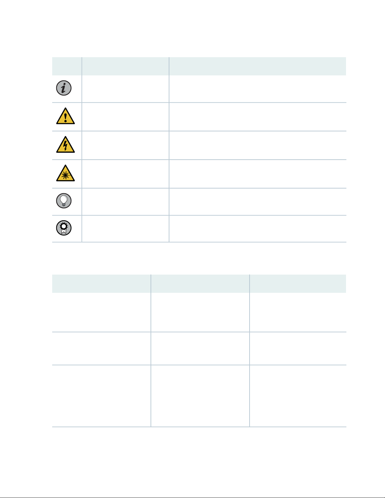
Table 1: Notice Icons
xiv
DescriptionMeaningIcon
Indicates important features or instructions.Informational note
Caution
Indicates a situation that might result in loss of data or hardware
damage.
Alerts you to the risk of personal injury or death.Warning
Alerts you to the risk of personal injury from a laser.Laser warning
Indicates helpful information.Tip
Alerts you to a recommended use or implementation.Best practice
Table 2 on page xiv defines the text and syntax conventions used in this guide.
Table 2: Text and Syntax Conventions
ExamplesDescriptionConvention
Fixed-width text like this
Italic text like this
Represents text that you type.Bold text like this
Represents output that appears on
the terminal screen.
Introduces or emphasizes important
•
new terms.
Identifies guide names.
•
Identifies RFC and Internet draft
•
titles.
To enter configuration mode, type
the configure command:
user@host> configure
user@host> show chassis alarms
No alarms currently active
A policy term is a named structure
•
that defines match conditions and
actions.
Junos OS CLI User Guide
•
RFC 1997, BGP Communities
•
Attribute
Page 15

Table 2: Text and Syntax Conventions (continued)
xv
ExamplesDescriptionConvention
Italic text like this
Text like this
< > (angle brackets)
| (pipe symbol)
Represents variables (options for
which you substitute a value) in
commands or configuration
statements.
Represents names of configuration
statements, commands, files, and
directories; configuration hierarchy
levels; or labels on routing platform
components.
variables.
Indicates a choice between the
mutually exclusive keywords or
variables on either side of the symbol.
The set of choices is often enclosed
in parentheses for clarity.
Configure the machine’s domain
name:
[edit]
root@# set system domain-name
domain-name
To configure a stub area, include
•
the stub statement at the [edit
protocols ospf area area-id]
hierarchy level.
The console port is labeled
•
CONSOLE.
stub <default-metric metric>;Encloses optional keywords or
broadcast | multicast
(string1 | string2 | string3)
# (pound sign)
[ ] (square brackets)
Indention and braces ( { } )
; (semicolon)
GUI Conventions
Indicates a comment specified on the
same line as the configuration
statement to which it applies.
Encloses a variable for which you can
substitute one or more values.
Identifies a level in the configuration
hierarchy.
Identifies a leaf statement at a
configuration hierarchy level.
rsvp { # Required for dynamic MPLS
only
community name members [
community-ids ]
[edit]
routing-options {
static {
route default {
nexthop address;
retain;
}
}
}
Page 16
Table 2: Text and Syntax Conventions (continued)
xvi
ExamplesDescriptionConvention
Bold text like this
> (bold right angle bracket)
Represents graphical user interface
(GUI) items you click or select.
Separates levels in a hierarchy of
menu selections.
In the Logical Interfaces box, select
•
All Interfaces.
To cancel the configuration, click
•
Cancel.
In the configuration editor hierarchy,
select Protocols>Ospf.
Documentation Feedback
We encourage you to provide feedback so that we can improve our documentation. You can use either
of the following methods:
Online feedback system—Click TechLibrary Feedback, on the lower right of any page on the Juniper
•
Networks TechLibrary site, and do one of the following:
Click the thumbs-up icon if the information on the page was helpful to you.
•
Click the thumbs-down icon if the information on the page was not helpful to you or if you have
•
suggestions for improvement, and use the pop-up form to provide feedback.
E-mail—Send your comments to techpubs-comments@juniper.net. Include the document or topic name,
•
URL or page number, and software version (if applicable).
Requesting Technical Support
Technical product support is available through the Juniper Networks Technical Assistance Center (JTAC).
If you are a customer with an active Juniper Care or Partner Support Services support contract, or are
Page 17

covered under warranty, and need post-sales technical support, you can access our tools and resources
online or open a case with JTAC.
JTAC policies—For a complete understanding of our JTAC procedures and policies, review the JTAC User
•
Guide located at https://www.juniper.net/us/en/local/pdf/resource-guides/7100059-en.pdf.
Product warranties—For product warranty information, visit https://www.juniper.net/support/warranty/.
•
JTAC hours of operation—The JTAC centers have resources available 24 hours a day, 7 days a week,
•
365 days a year.
Self-Help Online Tools and Resources
For quick and easy problem resolution, Juniper Networks has designed an online self-service portal called
the Customer Support Center (CSC) that provides you with the following features:
Find CSC offerings: https://www.juniper.net/customers/support/
•
Search for known bugs: https://prsearch.juniper.net/
•
xvii
Find product documentation: https://www.juniper.net/documentation/
•
Find solutions and answer questions using our Knowledge Base: https://kb.juniper.net/
•
Download the latest versions of software and review release notes:
•
https://www.juniper.net/customers/csc/software/
Search technical bulletins for relevant hardware and software notifications:
•
https://kb.juniper.net/InfoCenter/
Join and participate in the Juniper Networks Community Forum:
•
https://www.juniper.net/company/communities/
Create a service request online: https://myjuniper.juniper.net
•
To verify service entitlement by product serial number, use our Serial Number Entitlement (SNE) Tool:
https://entitlementsearch.juniper.net/entitlementsearch/
Creating a Service Request with JTAC
You can create a service request with JTAC on the Web or by telephone.
Visit https://myjuniper.juniper.net.
•
Call 1-888-314-JTAC (1-888-314-5822 toll-free in the USA, Canada, and Mexico).
•
For international or direct-dial options in countries without toll-free numbers, see
https://support.juniper.net/support/requesting-support/.
Page 18

1
CHAPTER
Overview
PTX10004 System Overview | 19
PTX10004 Chassis | 33
PTX10004 Cooling System | 40
PTX10004 Power System | 54
PTX10004 Routing and Control Board Components and Descriptions | 62
PTX10004 Switch Fabric | 68
PTX10004 Line Card Components and Descriptions | 70
Page 19
PTX10004 System Overview
IN THIS SECTION
PTX10004 Hardware Overview | 19
PTX10004 Components and Configurations | 28
PTX10004 Component Redundancy | 30
PTX10004 Hardware and CLI Terminology Mapping | 31
PTX10004 Hardware Overview
19
IN THIS SECTION
System Overview | 19
Benefits | 20
Chassis Description | 20
Switch Fabric | 22
Routing and Control Board | 23
Line Cards | 24
Cooling System | 25
Power Supplies | 26
Software | 27
The Juniper Networks PTX10004 Packet Transport Router addresses the business challenges of carriers
and content providers to deliver more traffic at lower costs. For more information, read the following
topics.
System Overview
The PTX10004 is the most compact, high-density, and power-efficient modular chassis in the PTX10000
line of modular packet-routing transport routers. At only 7 U in height, the PTX10004 is designed for
Page 20

today’s space-constrained facilities. Like the larger PTX10008 router, the PTX10004 supports Juniper’s
400GbE architecture with inline Media Access Control Security (MACsec) on all ports for point-to-point
security on Ethernet links. Each PTX10K-LC1201-36CD line card has a throughput of up to 14.4 Tbps,
giving the chassis an effective switching capacity of 57.6 Tbps. That throughput means a fully equipped
PTX10004 can support 576 10GbE, 576 25GbE, 144 40GbE, 576 100GbE, or 144 400GbE interfaces in
a single chassis. The PTX10004 supports the same feature set and runs the same Junos OS Evolved
operating system as the PTX10008.
Benefits
The PTX10004 Packet Transport Router is the small-footprint complement to the larger PTX10008 modular
chassis with these benefits:
Ease of deployment—The PTX10004 features a compact 7-U modular chassis for sites with limited space
•
or power.
Modular, flexible design—The PTX10004 uses the custom silicon line-cards (14.4 Tbps and 9.6 Tbps
•
throughput) and power supplies found in the larger PTX10008 modular chassis.
20
Proven fabric and chassis design—The PTX10004 has the same updated fabric and chassis design features
•
found on the PTX10008 router.
Chassis Description
The PTX10004 router is 7-U tall. You can fix up to six PTX10004 routers in a standard 42-U rack with
adequate cooling and power. All key PTX10004 router components are field-replaceable units (FRUs).
Figure 1 on page 21 illustrates the key components visible from the front of the chassis, Figure 2 on page 21
illustrates the components that are visible from the rear of the chassis, and Figure 3 on page 22 illustrates
the components that are internal to the chassis.
Page 21
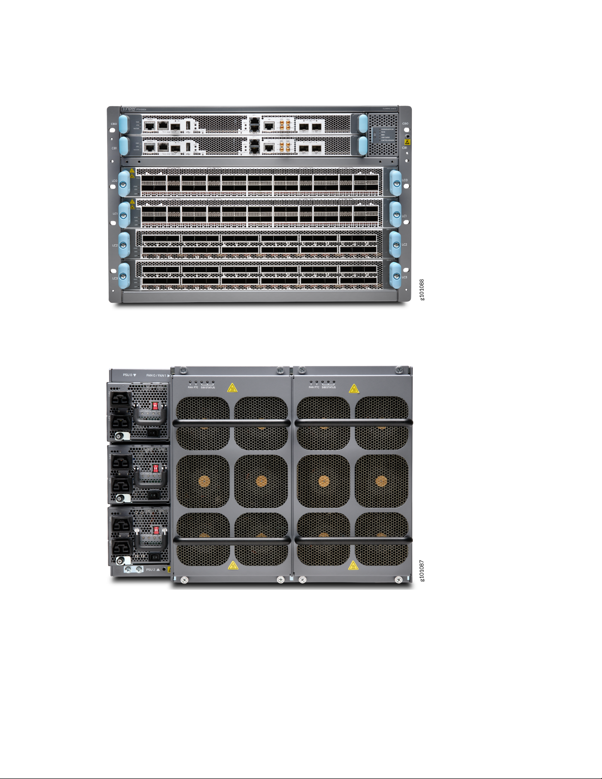
Figure 1: PTX10004 Chassis Front
21
Figure 2: PTX10004 Chassis Rear
Page 22
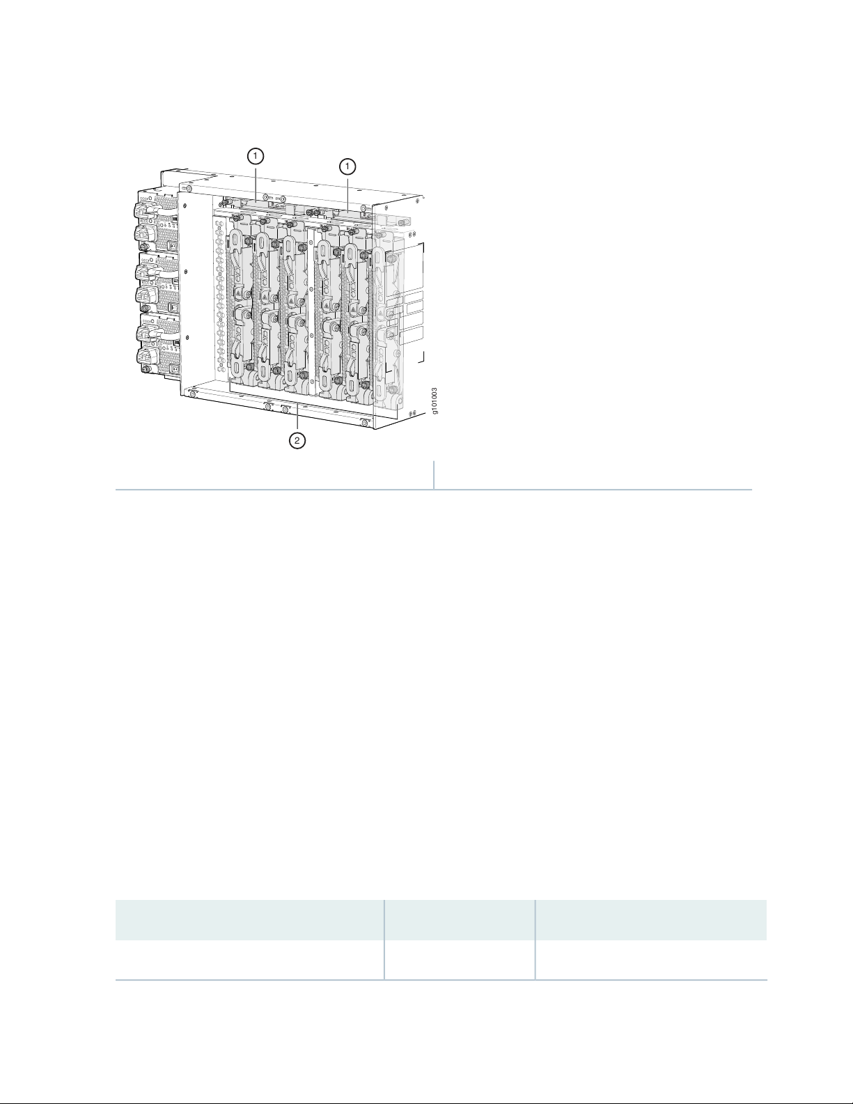
Figure 3: PTX10004 Chassis Internal Components
g101003
2
1
1
22
2—1— Switch fabricFan tray controllers
See “PTX10004 Chassis Physical Specifications” on page 33 and “PTX10004 Field-Replaceable Units” on
page 35.
Switch Fabric
Switch Interface Boards (SIBs) create the switch fabric for the PTX10004. Each SIB has a set of connectors
to mate the line cards and the Routing and Control Board (RCB) to the switch fabric. See Figure 4 on page 23
for an example of the JNP10004-SF3.
For the JNP10004 switch fabric, three SIBs provide the minimum switching functionality to a PTX10004
router; six SIBs provide full throughput. SIBs are installed between the line cards and the fan trays inside
the chassis. Each PTX10004 SIB has four connectors that match to a line-card slot, eliminating the need
for a backplane. See “PTX10004 Switch Interface Board Description” on page 68.
You can order the PTX10004 with different SIB configurations that allow you to grow your system as
needed. See Table 3 on page 22. For full 400 Gbps deployments, we recommend the PTX10004-PREM3
configuration. See “PTX10004 Components and Configurations” on page 28 for a full description of these
configuration options.
Table 3: Switch Fabric Configuration Overview
Forwarding CapacityNumber of SIBsConfiguration
28.8 Tbps3PTX10004-BASE3
Page 23
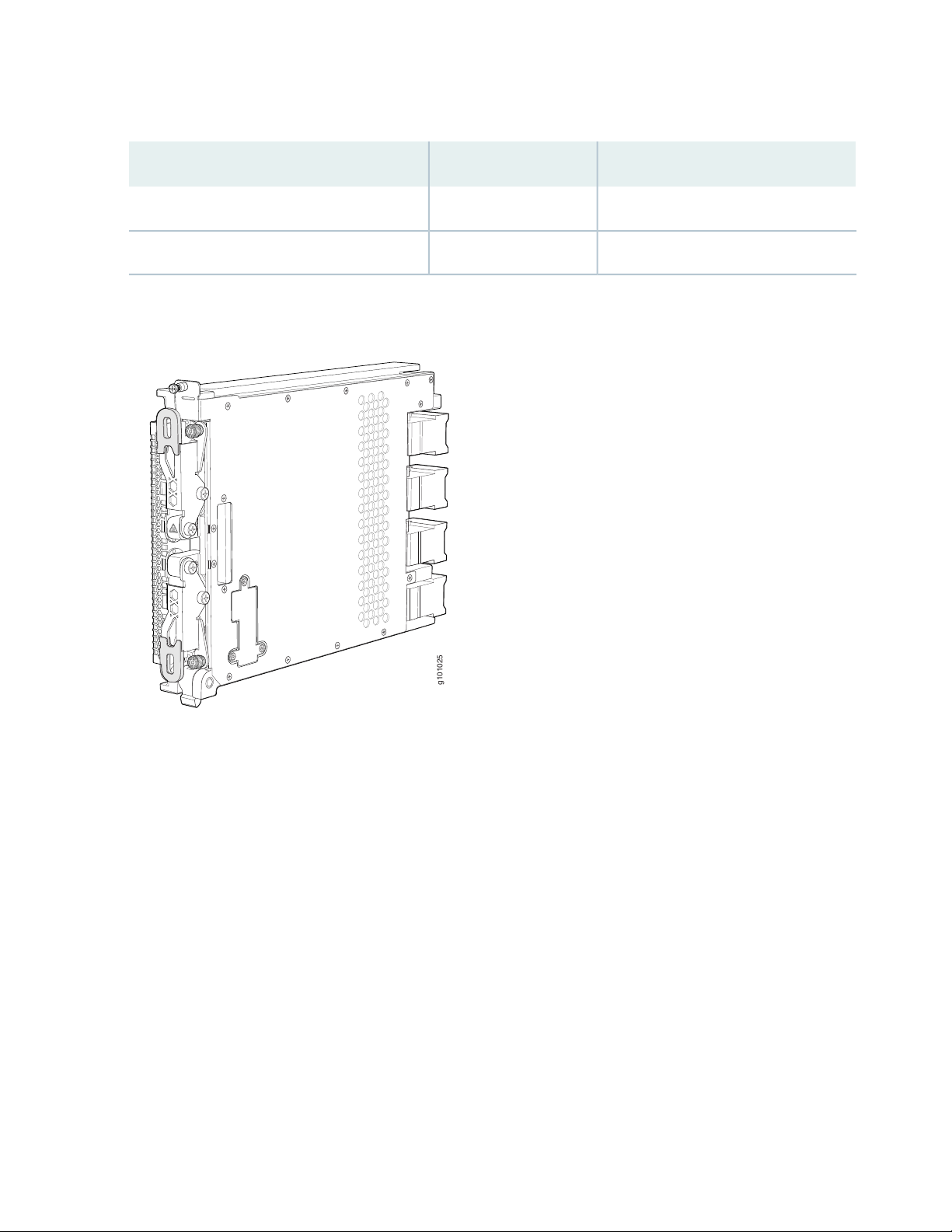
Table 3: Switch Fabric Configuration Overview (continued)
g101025
Figure 4: JNP10004-SF 3 SIB
23
Forwarding CapacityNumber of SIBsConfiguration
38.4 Tbps4PTX10004–PREM2
57.6 Tbps6PTX10004-PREM3
Routing and Control Board
The Routing and Control Board (RCB) contains a Routing Engine and is responsible for system management
and system control in the PTX10004. See “PTX10004 Routing and Control Board Components and
Descriptions” on page 62. RCBs are field-replaceable units (FRUs) that are installed in the front of the
chassis in the slots labeled CB0 and CB1.
The supported models of RCB for JNP10008-SF3 fabric systems are:
JNP10K-RE1-E, 64 gigabytes of memory
•
JNP10K-RE1-E128, 128 gigabytes of memory
•
These RCBs runs Junos OS Evolved. See Figure 5 on page 24.
Page 24
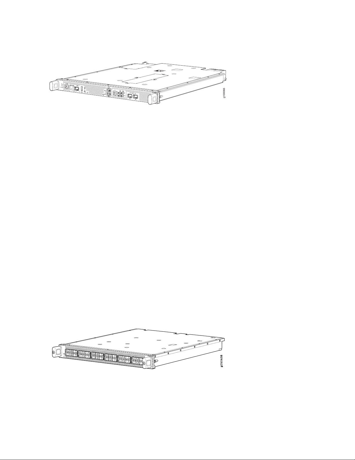
Figure 5: JNP10K-RE1-E, and JNP10K-RE1-E128
g100066
The base configuration has a single RCB. The fully redundant configurations have two RCBs. The RCB also
contains Precision Time Protocol (PTP) ports and four Media Access Control Security (MACsec) capable
ports. See “PTX10004 Components and Configurations” on page 28.
Line Cards
The PTX10004 has four horizontal line-card slots. The line cards combine a Packet Forwarding Engine and
Ethernet interfaces enclosed in a single assembly. The PTX10004 line-card architecture is based on a
number of identical, independent Packet Forwarding Engine slices. Line cards are FRUs that can be installed
in the line-card slots labeled 0 through 3 (top to bottom) on the front of the chassis. All line cards are
hot-removable and hot-insertable. After the hot insertion, you need to bring the card online (see “Take a
PTX10004 Line Card Online or Offline” on page 209).
24
The PTX10004 supports:
PTX10K-LC1201-36CD—a 36-port multiple-speed line card that can be configured as 400GbE, 200GbE,
•
100GbE, 50GbE, 25GbE, or 10GbE Ethernet ports.
PTX10K-LC1202-36MR—A 36-port line card (thirty-two 100GbE ports and four 400GbE ports). The
•
400-Gigabit Ethernet ports can be configured as either 400-Gigabit uplinks or channelized to 4
independent 100-Gigabit downstream ports.
See Figure 6 on page 24 for an example of a PTX10004 line card.
Figure 6: PTX10K-LC1201-36CD Line Card
Page 25
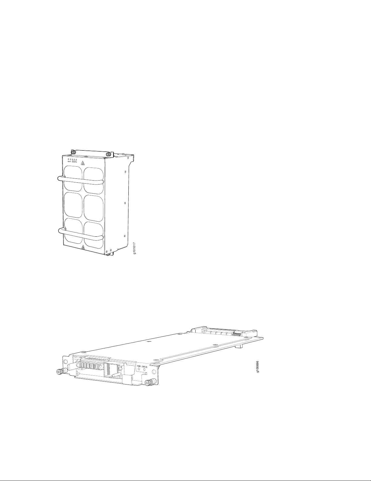
Cooling System
g101017
g100696
The cooling system in a PTX10004 consists of two fan trays (see Figure 7 on page 25) and two fan tray
controllers (see Figure 8 on page 25).
The JNP10004-FAN2 fan tray contains an array of six fans and operates as a single hot-removable and
hot-insertable field-replaceable unit (FRU). The fan trays install vertically on the rear of the chassis and
provide front-to-back chassis cooling. See “PTX10004 Cooling System and Airflow” on page 40.
Figure 7: Fan Tray JNP10004-FAN2
25
There is a corresponding fan tray controller, JNP10004-FTC2, for each JNP10004-FAN2 fan tray. See
Figure 8 on page 25.
Figure 8: Fan Tray Controller JNP10004-FTC2
Page 26
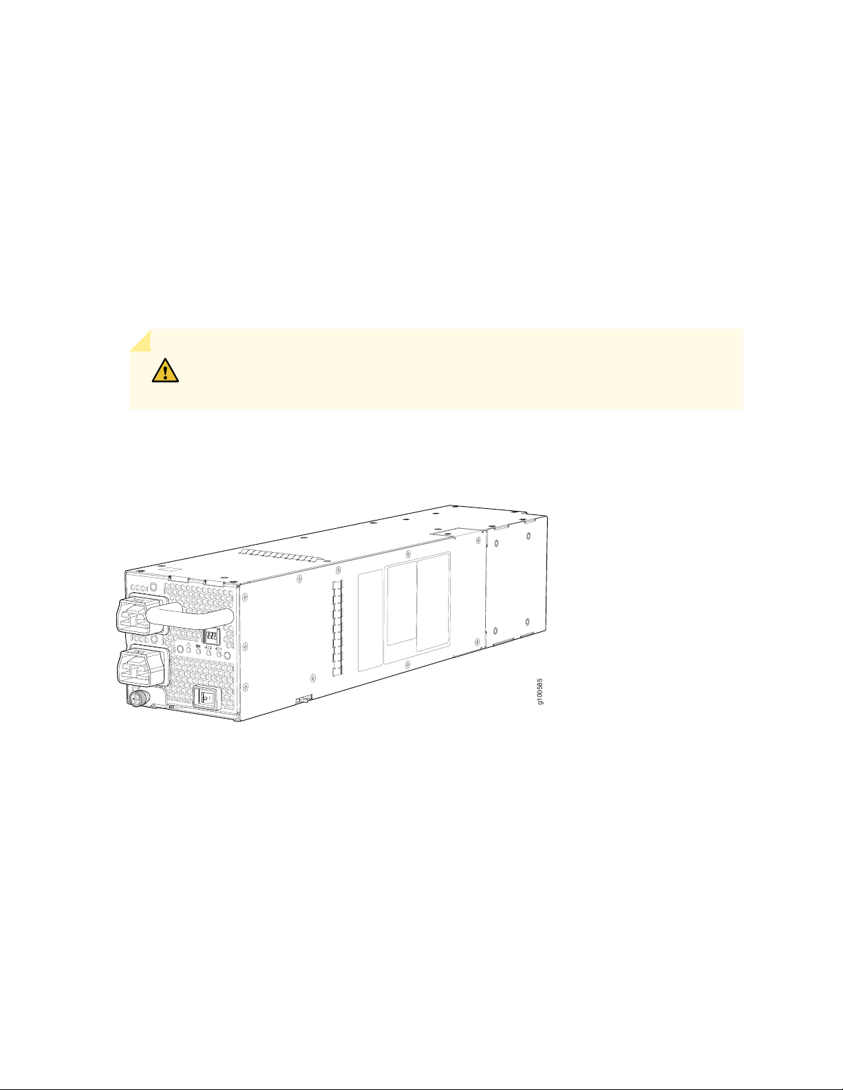
Power Supplies
g100585
The PTX10004 router support AC, DC, high-voltage alternating current (HVAC), and high-voltage direct
current (HVDC), by offering the following power supplies:
JNP10K-PWR-AC2
•
JNP10K-PWR-DC2
•
Power supplies for the PTX10004 are load-sharing hot-removable and hot-insertable FRUs. The router
operates with three power supplies. Each power supply has an internal fan for cooling. You can install the
power supplies in any slot. See Figure 9 on page 26 and Figure 10 on page 27.
CAUTION: Do not mix power supply models in the same chassis in a running
environment.
26
Figure 9: JNP10K-PWR-AC2 Power Supply
Page 27

Figure 10: JNP10K-PWR-DC2 Power Supply
g100595
Table 4 on page 27 provides an overview of the differences between the power supplies.
Table 4: Power Supply Overview
WattageInput TypePower Supply Model
27
5000 W, single feed; 5500 W, dual feedAC, HVAC, or HVDCJNP10K-PWR-AC2
2750 W, single feed; 5500 W, dual feedDC onlyJNP10K-PWR-DC2
The PTX10004 supports four PTX10K-LC1201-36CD line cards in non-redundant mode. If you populate
all four slots with this line card, a power alarm is raised, which is expected behavior.
Software
The Juniper Networks PTX10004 packet transport router runs on the Junos OS Evolved operating system,
which provides Layer 3 routing services. Junos OS Evolved is the next-generation Junos OS. It has the
same CLI, the same features, and, in some cases, even the same processes as in the previous versions of
Junos OS. However, its infrastructure is entirely modernized.
SEE ALSO
PTX10004 Cooling System and Airflow | 40
PTX10004 Field-Replaceable Units | 35
PTX10004 Power System | 54
Page 28

PTX10004 Components and Configurations
IN THIS SECTION
PTX10004 Configurations | 28
PTX10004 Configurations
Table 5 on page 28 lists the hardware configurations for a PTX10004 modular chassis and the components
included in each configuration.
Table 5: PTX10004 Hardware Configurations
Configuration ComponentsRouter Configuration
28
Base AC configuration
PTX10004-BASE3
Base DC configuration
PTX10004-BASE3
Chassis (JNP10004-CHAS)
•
One RCB (JNP10K-RE1-E or JNP10K-RE1-E128)
•
Two fan tray controllers (JNP10004-FTC2)
•
Two fan trays (JNP10004-FAN2)
•
Three AC power supplies (JNP10K-PWR-AC2)
•
Three SIBs (JNP10004-SF3)
•
Three SIB covers (JNP10004-SF3-BLNK)
•
Four line-card covers (JNP10K-LC-BLNK)
•
One RCB cover
•
Front door (JNP10004-FRNT-PNL)
•
Chassis (JNP10004-CHAS)
•
One RCB (JNP10K-RE1-E or JNP10K-RE1-E128)
•
Two fan tray controllers (JNP10004-FTC2)
•
Two fan trays (JNP10004-FAN2)
•
Three DC power supplies (JNP10K-PWR-DC2)
•
Three SIBs (JNP10004-SF3)
•
Three SIB covers (JNP10004-SF-BLNK2)
•
Four line-card covers (JNP10K-LC-BLNK)
•
One RCB cover
•
Front door (JNP10004-FRNT-PNL)
•
Page 29

Table 5: PTX10004 Hardware Configurations (continued)
Configuration ComponentsRouter Configuration
29
Redundant AC configuration
PTX10004-PREM2
Redundant DC configuration
PTX10004-PREM2
Chassis (JNP10004-CHAS)
•
Two RCBs (JNP10K-RE1-E or JNP10K-RE1-E128)
•
Two fan tray controllers (JNP10004-FTC2)
•
Two fan trays (JNP10004-FAN2)
•
Three AC power supplies (JNP10K-PWR-AC2)
•
Four SIBs (JNP10004-SF3)
•
Two SIB covers (JNP10004-SF-BLNK2))
•
Four line-card covers (JNP10K-LC-BLNK)
•
Front door (JNP10004-FRNT-PNL)
•
Chassis (JNP10004-CHAS)
•
Two RCBs (JNP10K-RE1-E or JNP10K-RE1-E128)
•
Two fan tray controllers (JNP10004-FTC2)
•
Two fan trays (JNP10004-FAN2)
•
Three DC power supplies (JNP10K-PWR-DC2)
•
Four SIBs (JNP10004-SF3)
•
Four line-card covers (JNP10K-LC-BLNK)
•
Front door (JNP10004-FRNT-PNL)
•
Fully redundant AC configuration
PTX10004-PREM3
Fully redundant DC configuration
PTX10004-PREM3
Chassis (JNP10004-CHAS)
•
Two RCBs (JNP10K-RE1-E or JNP10K-RE1-E128)
•
Two fan tray controllers (JNP10004-FTC2)
•
Two fan trays (JNP10004-FAN2)
•
Three AC power supplies (JNP10K-PWR-AC2)
•
Six SIBs (JNP10004-SF3)
•
Four line-card covers (JNP10K-LC-BLNK)
•
Front door (JNP10004-FRNT-PNL)
•
Chassis (JNP10004-CHAS)
•
Two RCBs (JNP10K-RE1-E or JNP10K-RE1-E128)
•
Two fan tray controllers ( JNP10004-FTC2)
•
Two fan trays (JNP10004-FAN2)
•
Three DC power supplies (JNP10K-PWR-DC2)
•
Six SIBs (JNP10004-SF3)
•
Four line-card covers (JNP10K-LC-BLNK)
•
Front door (JNP10004-FRNT-PNL)
•
Page 30

NOTE: Line cards and the cable management system are not part of the base or redundant
configuration. You must order them separately.
NOTE: If you want to purchase additional power supplies (AC, DC, HVAC, or HVDC), SIBs, or
RCBs for your router configuration, you must order them separately.
SEE ALSO
PTX10004 Routing and Control Board Description | 62
JNP10K-PWR-AC2 Power Supply | 54
JNP10K-PWR-DC2 Power Supply | 56
30
PTX10004 Switch Interface Board Description | 68
PTX10004 Component Redundancy
The PTX10004 router is designed so that no single point of failure can cause the entire system to fail. The
following major hardware components in the redundant configuration provide redundancy:
Routing and Control Board (RCB)—The RCB consolidates the Routing Engine function with the control
•
plane function in a single unit. The PTX10004 router can have one or two RCBs. When two RCBs are
installed, one functions as the primary and the other functions as the backup. If the primary RCB (or
either of its components) fails, the backup can take over as the primary. See “PTX10004 Routing and
Control Board Description” on page 62.
Switch Interface Boards (SIBs)—The PTX10004 has six SIB slots for the JNP10004-SF3 SIBs. The switch
•
fabric requires a minimum of three SIBs (BASE3 configuration) to provide the minimum switching
functionality to a PTX10004 router. You can install up to six SIBs (PREM3 configuration), which is required
for 14.4 Tbps line card support. However, a fully-loaded PTX10004 chassis with PTX10K-LC1201-36CD
line cards is not a redundant configuration. See the “PTX10004 Switch Interface Board Description” on
page 68.
Power supplies—The system requires three power supplies for minimum operation (two RCBs, two fan
•
trays, three SIBs, and no line cards). The three power supplies provide n+1 redundancy for systems
running 4.8-Tbps line cards and can tolerate a failure of a single power supply without system interruption.
If one power supply fails in a fully redundant system, the other power supplies can provide full power
Page 31

to the PTX10004 router indefinitely. However, configurations that run 14.4-Tbps line cards in all four
line-card slots don’t have redundant power. You can populate and run the 14.4-Tbps line cards but a
power alarm is raised, which is expected behavior.
The PTX10004 router also supports power source redundancy. Four sets of lugs are provided for the
JNP10K-PWR-DC2 cables, and two AC power cords are provided for each JNP10K-PWR-AC2 power
supply.
Cooling system—The PTX10004 has two fan trays, which are controlled by the fan tray controller. Each
•
fan tray has a corresponding fan tray controller. If one of the fans in a JNP10004-FAN2 fan tray fails,
under most conditions the fan tray rebalances the remaining fans to continue. The fan tray continues
to operate indefinitely and provide sufficient cooling even when a single rotor fails in a fan, provided
the room temperature is within the operating range. See “PTX10004 Cooling System and Airflow” on
page 40.
PTX10004 Hardware and CLI Terminology Mapping
31
This topic describes the hardware terms used in PTX10004 router documentation and the corresponding
terms used in the Junos OS CLI. See Table 6 on page 31.
Table 6: CLI Equivalents of Terms Used in Documentation for PTX10004 Routers
Hardware
Item (CLI)
FPC (n)
JNP10004-FAN2Fan tray
Abbreviation for the
Flexible PIC
Concentrator (FPC)
On PTX10004, an
FPC is equivalent to
a line card.
n is a value in the range
of 0–11. The value
corresponds to the
individual fan number in
the fan tray.
n is a value in the range
of 0–3 for the
PTX10004. The value
corresponds to the
line-card slot number in
which the line card is
installed.
Item In
DocumentationValue (CLI)Description (CLI)
Router chassis–PTX10004Chassis
Fan trayFan Tray 0|1 Fan n
Line card (The
router doesn’t
have actual
FPCs—the line
cards are the
FPC
equivalents on
the router.)
Additional Information
“PTX10004 Chassis Physical
Specifications” on page 33
“PTX10004 Cooling System and
Airflow” on page 40
Understanding Interface Naming
Conventions
Page 32

Table 6: CLI Equivalents of Terms Used in Documentation for PTX10004 Routers (continued)
32
Hardware
Item (CLI)
PSM (n)
Engine
Abbreviation for
power supply
module
One of the
following:
JNP10K-PWR-AC2
•
JNP10K-PWR-DC2
•
RE (n)Routing
n is a value in the range
of 0–2. The value
corresponds to the
power-supply slot
number.
of 0–1.
Multiple line items
appear in the CLI if more
than one RCB is installed
in the chassis.
Item In
DocumentationValue (CLI)Description (CLI)
–Value of n is always 0.–PIC (n)
AC, DC,
HVAC, or
HVDC power
supply
RCBn is a value in the range
Additional Information
Understanding Interface Naming
Conventions
One of the following:
JNP10K-PWR-AC2 Power
•
Supply on page 54
JNP10K-PWR-DC2 Power
•
Supply on page 56
“PTX10004 Routing and Control
Board Components and
Descriptions” on page 62
SIB (n)
Xcvr (n)
This field indicates:
State of the fabric
•
plane:
Active
•
Spare
•
Check
•
Status of the
•
Packet
Forwarding
Engine in each
fabric plane:
Links OK
•
Error
•
Abbreviation for the
transceiver
of 0–5.
n is a value equivalent to
the number of the port
in which the transceiver
is installed.
Optical
transceivers
show chassis fabric sibsFabric planen is a value in the range
“PTX10004 Optical Transceiver
and Cable Support” on page 105
Page 33

PTX10004 Chassis
IN THIS SECTION
PTX10004 Chassis Physical Specifications | 33
PTX10004 Field-Replaceable Units | 35
PTX10004 Status Panel | 37
PTX10004 Optional Equipment | 39
The PTX10004 chassis houses the hardware components. The chassis components include the fan trays,
fan tray controllers, power supplies, Routing and Control Boards (RCBs), line cards, an optional cable
management system, and the status panel.
33
PTX10004 Chassis Physical Specifications
The PTX10004 modular chassis is a rigid sheet-metal structure that houses the other router components.
You can mount up to six PTX10004 routers in a standard 19-in. 4-post rack (42 U) provided the rack can
handle the combined weight and there is adequate power and cooling. See Figure 11 on page 34 to help
identify the major components and see Table 7 on page 34 for the physical specifications of the chassis
of these components.
Page 34

Figure 11: Front View of the PTX10004
g101000
1
4
2 3
34
3—1— HandlesRCBs
WARNING: The handles on each side of the chassis facilitate the fine-tune positioning
of the chassis on the base brackets. Do not use the handles to lift the chassis, even
when the chassis is empty. See “Mount a PTX10004 in a Four-Post Rack Using a
Mechanical Lift” on page 129 or “Manually Mount a PTX10004 in a Four-Post Rack” on
page 132 for instructions on properly moving a loaded chassis.
Table 7: PTX10004 Router Physical Specifications
Chassis, spare
173 lb (78 kg) with
pallet
12.2 in. (33 cm)110 lb (50 kg)
4—2— Line cardsStatus panel
DepthWidthHeightWeightDescription
17.4 in. (44.2 cm)
NOTE: The outer
edges of the chassis
flange extend the
width to 19 in.
(48.3 cm).
35 in. (88.9 cm)
chassis only
42.4 in. (107.7 cm)
with EMI door
Page 35

Table 7: PTX10004 Router Physical Specifications (continued)
35
DepthWidthHeightWeightDescription
Chassis
PTX10004-BASE3
AC or DC
configuration
Chassis
PTX10004-PREM2
AC or DC
configuration
Chassis redundant
PTX10004-PREM3
AC or DC
configuration
303 lb (137 kg) with
pallet
323 lb (147 kg) with
pallet
335 lb (152 kg) with
pallet
12.2 in. (33 cm)240 lb (109 kg)
12.2 in. (33 cm)260 lb (117 kg)
12.2 in. (33 cm)272 lb (123 kg)
17.4 in. (44.2 cm)
NOTE: The outer
edges of the chassis
flange extend the
width to 19 in.
(48.3 cm).
17.4 in. (44.2 cm)
NOTE: The outer
edges of the chassis
flange extend the
width to 19 in.
(48.3 cm).
17.4 in. (44.2 cm)
NOTE: The outer
edges of the chassis
flange extend the
width to 19 in.
(48.3 cm).
35 in. (88.9 cm) with
JNP10K-PWR-AC2
power supplies
42.4 in. (107.7 cm)
with EMI door
35 in. (88.9 cm) with
JNP10K-PWR-DC2
power supplies
42.4 in. (107.7 cm)
with EMI door
35 in. (88.9 cm) with
JNP10K-PWR-AC2
power supplies
42.4 in. (107.7 cm))
with EMI door
21.3 in. (54.1 cm)17.2 in. (43.7 cm)12.2 in. (33 cm)31 lb (14.06 kg)JNP10K-LC1201 line
card
21.3 in. (54.1 cm)17.2 in. (43.68 cm)1.9 in. (4.8 cm)21 lb (9.5 kg)PTX10K-LC1202-36MR
PTX10004 Field-Replaceable Units
Field-replaceable units (FRUs) are router components that you can replace at your site. The router uses
the following types of FRUs:
Hot-insertable and hot-removable—You can remove and replace these components without powering
•
off the router or disrupting the routing function.
Hot-pluggable—You can remove and replace these components without powering off the router, but
•
the routing function is interrupted until you replace the component.
Table 8 on page 36 lists the FRUs and their types for the PTX10004 routers.
Page 36

Table 8: FRUs in a PTX10004
36
TypeFRU
Hot-insertable and hot-removable.Power supplies
Hot-insertable and hot-removable.Fan trays
Hot-insertable and hot-removable.Fan tray controllers
Routing and Control Boards
(RCBs)
Switch Interface Boards (SIBs)
Line cards
Redundant configuration:
Primary RCB is hot-pluggable.
•
Backup RCB is hot-insertable and hot-removable.
•
Base configuration:
Removal of the RCB causes the router to shut down. To prevent traffic disruption,
•
take the chassis offline. If a temporary disruption is acceptable, you can install
a replacement RCB in the second slot. The system restarts to elect a primary
RCB and a backup RCBs If necessary, you can manually switch the primary and
backup RCB using the request chassis routing-engine master switch command.
SIBs are hot-insertable and hot-removable. We recommend that you take SIBs
offline before removing them to avoid traffic loss while the router fabric is being
reconfigured. Use the following command:
user@router> request chassis sib slot slot-number offline
Hot-insertable. We recommend that you take line cards offline before removing
them. Use the following command:
user@router> request chassis fpc-slot slot-number offline
Hot-insertable and hot-removable.Optical transceivers
See “PTX10004 Optical
Transceiver and Cable Support”
on page 105 for how to find
detailed specifications and the
Junos OS release in which the
transceivers were introduced.
NOTE: Line cards are not part of the base or redundant configuration. You must order them
separately.
Page 37

NOTE: If you have a Juniper Care service contract, register any addition, change, or upgrade of
g100339
hardware components at https://www.juniper.net/customers/support/tools/updateinstallbase/.
Failure to do so can result in significant delays if you need replacement parts. This note does
not apply if you replace an existing component with the same type of component.
SEE ALSO
PTX10004 Components and Configurations | 28
PTX10004 Optical Transceiver and Cable Support | 105
PTX10004 Status Panel
37
The PTX10004 status panel shows the overall status of the chassis.
PTX10004 chassis ship with an enhanced power bus to future-proof the chassis for potential power growth.
The status panel indicates the chassis status through a set of five bicolor LEDs. It has an Azure blue stripe
along the left side of the LEDs. See Figure 12 on page 37 for a chassis status panel.
Figure 12: Status Panel on the Chassis
Table 9 on page 38 describes the status panel LEDs.
Page 38

Table 9: Status Panel LEDs on a PTX10004
warning symbol)
warning symbol)
38
DescriptionStateColorName
No minor alarms are active.OffYellow! Minor alarm (Triangle
A minor alarm is active.On steadily
No minor alarms are active.OffYellowAlarm (Bell symbol)
A minor alarm is active.On steadily
No major alarms are active.OffRed
A major alarm is active.On steadily
No major alarms are active.OffRed! Major alarm (Circle
A major alarm is active.On steadily
On steadilyGreenPOWER SUPPLIES
BlinkingYellow
OffNone
On steadilyGreenFANS
BlinkingYellow
OffNone
On steadilyGreenSIBS
All of the power supplies are online and
operating normally.
One or more of the power supplies has an
error.
None of the power supplies is receiving
power.
The fans and the fan tray controllers are
online and operating normally.
There is an error in a fan or in one of the
fan tray controllers.
The fan tray controllers and fan trays are
not receiving power.
At least one installed Switch Interface
Board (SIB) is online.
BlinkingYellow
There is a hardware error in one or more
SIBs.
All the SIBs are offline.OffNone
Page 39

Table 9: Status Panel LEDs on a PTX10004 (continued)
39
DescriptionStateColorName
At least one installed line card is online.On steadilyGreenLINE CARDS
BlinkingYellow
On steadilyGreenCONTROL BOARDS
There is a hardware error in one or more
line cards.
All the line cards are offline.OffNone
All installed Routing and Control Boards
(RCBs) are online.
One or more RCBs have an error condition.BlinkingYellow
The installed RCBs are offline.OffNone
PTX10004 Optional Equipment
The PTX10004 routers offers a cable management system (JLC-CBL-MGMT-KIT) and an electrostatic
discharge (ESD) front door with an air filter (JNP10004-FPNL1) a as optional equipment. An ESD front
door (JNP10004-FRNT-PNL) without an air filter comes standard with each configuration.
SEE ALSO
Install the PTX10004 Cable Management System | 215
Install the Front Door on a PTX10004 | 137
RELATED DOCUMENTATION
How to Troubleshoot PTX10004 Error Conditions | 240
Page 40

PTX10004 Cooling System
IN THIS SECTION
PTX10004 Cooling System and Airflow | 40
PTX10004 Fan Tray LEDs and Fan Tray Controller LEDs | 47
The PTX10004 cooling system components work together to keep all components within the acceptable
temperature range. If the maximum temperature specification is exceeded and the system cannot be
adequately cooled, the Routing and Control Board (RCB) shuts down some or all of the hardware
components.
40
PTX10004 Cooling System and Airflow
IN THIS SECTION
Fan Tray | 40
Fan Tray Controller | 42
Airflow Direction in the PTX10004 | 46
The cooling system in a PTX10004 chassis consists of dual fan trays (JNP10004-FAN2) with matching
dual fan tray controllers (JNP10004-FTC2). Each fan tray requires a companion fan tray controller to be
installed and operational to be hot-insertable and hot-removable.
Fan Tray
The JNP10004-FAN2 fan tray contains an array of internal fans, a non-removable control board, and LEDs.
The two fan trays install vertically, side by side, next to the power supplies on the FRU side of the chassis.
Two handles on each front faceplate facilitate handling of the fan tray. See Figure 13 on page 41 and
Figure 14 on page 41.
Page 41

Figure 13: JNP10004-FAN2 Fan Tray
g101017
g101002
1
2
Figure 14: Installed Fan Trays on a PTX10004
41
2—1— Fan traysPower supplies
See Table 10 on page 41 for the physical specifications of the fan trays.
Table 10: Fan Tray Specifications
JNP10004-FAN2Specification
JNP10004-FTC2Corresponding fan tray controller model
6Number of fans per fan tray
12Number of fans per chassis
Page 42

Table 10: Fan Tray Specifications (continued)
42
JNP10004-FAN2Specification
0 through 11Fan numbering
948 CFM for both fan traysVolume flow at 100%
20.3R1-EVOIntroduced in Junos OS Release
12.08 in. (30.68 cm)Height
6.6 in. (16.8 cm)Width
Depth
5.5 in. (13.97 cm) without handles, 6.85 in. (17.4 cm) with
handles
9.8 lb (4.45 kg)Weight
The array of fans in both models operate as a single unit. If an individual fan in the array fails, the entire
fan tray must be replaced. However, the fan tray continues to operate indefinitely and provides sufficient
cooling even when a single rotor fails in a fan, provided the room temperature is within the operating
range.
If you want to replace an existing fan tray while the router is running, remove only one fan tray. The router
continues to operate for a limited time with a single operating fan tray without triggering a thermal alarm.
CAUTION: To avoid a thermal alarm, do not remove both fan trays while the router
is operating.
The internal fan control board in each fan tray contains the LEDs for the associated fan tray controllers
and the LEDs for the three SIBs directly behind the fan tray.
Fan Tray Controller
The PTX10004 supports two fan tray controllers to provide the control logic and power to hot-insert and
hot-remove a fan tray:
Page 43

JNP10004-FTC2—Supports model JNP10004-FAN2; see Figure 15 on page 43.
g100696
•
Figure 15: Fan Tray Controller JNP10004-FTC2
WARNING: Do not mix the fan tray controller models. Use only the supported fan
tray model for each fan tray controller. See Table 11 on page 43.
43
Table 11: Fan Tray Controller Specifications
JNP10004-FTC2Specification
JNP10004-FAN2Corresponding fan tray model
20.3R1-EVOIntroduced in Junos OS Release
1.5 in. (3.81 cm)Height
6.5 in. (15.24 cm)Width
12.4 in. (31.5 cm)Depth
1.1 lb (0.5 kg)Weight
The system continually monitors the temperature of critical parts across the chassis and adjusts the chassis
fan speed according to the temperature. Junos OS controls the fan speed. Under normal operating
conditions, the fans in the fan tray run at less than full speed. If one fan tray controller fails or appears
missing (such as when a SIB is being replaced), the other fan tray controller sets the fans to full speed. This
allows the router to continue to operate normally as long as the remaining fans cool the chassis sufficiently.
Use the show chassis fan command to see the status of individual fans and fan speed. The following
examples show the fan status for a system running JNP10004-FAN2.
Page 44

user@system> show chassis fan
Item Status % RPM Measurement
Fan Tray 0 Fan 0 Ok 59% 6300 RPM
Fan Tray 0 Fan 1 Ok 55% 7500 RPM
Fan Tray 0 Fan 2 Ok 60% 6450 RPM
Fan Tray 0 Fan 3 Ok 54% 7350 RPM
Fan Tray 0 Fan 4 Ok 59% 6300 RPM
Fan Tray 0 Fan 5 Ok 55% 7500 RPM
Fan Tray 0 Fan 6 Ok 59% 6300 RPM
Fan Tray 0 Fan 7 Ok 54% 7350 RPM
Fan Tray 0 Fan 8 Ok 60% 6450 RPM
Fan Tray 0 Fan 9 Ok 54% 7350 RPM
Fan Tray 0 Fan 10 Ok 59% 6300 RPM
Fan Tray 0 Fan 11 Ok 54% 7350 RPM
Fan Tray 1 Fan 0 Ok 59% 6300 RPM
Fan Tray 1 Fan 1 Ok 55% 7500 RPM
Fan Tray 1 Fan 2 Ok 59% 6300 RPM
Fan Tray 1 Fan 3 Ok 55% 7500 RPM
Fan Tray 1 Fan 4 Ok 60% 6450 RPM
Fan Tray 1 Fan 5 Ok 55% 7500 RPM
Fan Tray 1 Fan 6 Ok 59% 6300 RPM
Fan Tray 1 Fan 7 Ok 54% 7350 RPM
Fan Tray 1 Fan 8 Ok 60% 6450 RPM
Fan Tray 1 Fan 9 Ok 54% 7350 RPM
Fan Tray 1 Fan 10 Ok 54% 5850 RPM
Fan Tray 1 Fan 11 Ok 50% 6750 RPM
44
To determine the cooling of all the components in the system, use the show chassis environment command.
user@system> show chassis environment
Class Item Status Measurement
Temp PSM 0 Ok 31 degrees C / 87 degrees F
PSM 1 Ok 30 degrees C / 86 degrees F
CB 0 Intake A Temp Sensor Ok 29 degrees C / 84 degrees F
CB 0 Intake B Temp Sensor Ok 30 degrees C / 86 degrees F
CB 0 Exhaust A Temp Sensor Ok 32 degrees C / 89 degrees F
CB 0 Exhaust B Temp Sensor Ok 33 degrees C / 91 degrees F
CB 0 Middle Temp Sensor Ok 34 degrees C / 93 degrees F
CB 1 Intake A Temp Sensor Ok 28 degrees C / 82 degrees F
CB 1 Intake B Temp Sensor Ok 28 degrees C / 82 degrees F
CB 1 Exhaust A Temp Sensor Ok 31 degrees C / 87 degrees F
CB 1 Exhaust B Temp Sensor Ok 31 degrees C / 87 degrees F
CB 1 Middle Temp Sensor Ok 33 degrees C / 91 degrees F
Fan Tray 0 Inlet Temp Sensor Ok 26 degrees C / 78 degrees F
Page 45

Fan Tray 0 Outlet Temp Sensor Ok 32 degrees C / 89 degrees F
Fan Tray 1 Inlet Temp Sensor Ok 27 degrees C / 80 degrees F
Fan Tray 1 Outlet Temp Sensor Ok 32 degrees C / 89 degrees F
FPC 3 BT-0 HBM-0 Temperature Ok 53 degrees C / 127 degrees F
FPC 3 BT-0 HBM-1 Temperature Ok 54 degrees C / 129 degrees F
FPC 3 BT-1 HBM-0 Temperature Ok 53 degrees C / 127 degrees F
FPC 3 BT-1 HBM-1 Temperature Ok 53 degrees C / 127 degrees F
FPC 3 BT-2 HBM-0 Temperature Ok 53 degrees C / 127 degrees F
FPC 3 BT-2 HBM-1 Temperature Ok 55 degrees C / 131 degrees F
FPC 3 BT-3 HBM-0 Temperature Ok 60 degrees C / 140 degrees F
FPC 3 BT-3 HBM-1 Temperature Ok 57 degrees C / 134 degrees F
FPC 3 BT-4 HBM-0 Temperature Ok 54 degrees C / 129 degrees F
FPC 3 BT-4 HBM-1 Temperature Ok 54 degrees C / 129 degrees F
FPC 3 BT-0 Temp Sensor 1 Ok 83 degrees C / 181 degrees F
FPC 3 BT-0 Temp sensor 0 Ok 87 degrees C / 188 degrees F
FPC 3 BT-1 Temp Sensor 0 Ok 79 degrees C / 174 degrees F
FPC 3 BT-1 Temp Sensor 1 Ok 78 degrees C / 172 degrees F
FPC 3 BT-2 Temp Sensor 0 Ok 81 degrees C / 177 degrees F
FPC 3 BT-2 Temp Sensor 1 Ok 81 degrees C / 177 degrees F
FPC 3 CPU Temperature Ok 60 degrees C / 140 degrees F
FPC 3 DDR4 A Ok 44 degrees C / 111 degrees F
FPC 3 DDR4 B Ok 38 degrees C / 100 degrees F
FPC 3 Intake-A Temp sensor Ok 42 degrees C / 107 degrees F
FPC 3 Intake-B Temp sensor Ok 36 degrees C / 96 degrees F
FPC 3 BT-3 Temp Sensor 0 Ok 86 degrees C / 186 degrees F
FPC 3 BT-3 Temp Sensor 1 Ok 85 degrees C / 185 degrees F
FPC 3 BT-4 Temp Sensor 0 Ok 72 degrees C / 161 degrees F
FPC 3 BT-4 Temp Sensor 1 Ok 73 degrees C / 163 degrees F
FPC 3 Exhaust-A Temp Sensor Ok 53 degrees C / 127 degrees F
FPC 3 Exhaust-B Temp Sensor Ok 53 degrees C / 127 degrees F
FPC 3 Exhaust-C Temp Sensor Ok 48 degrees C / 118 degrees F
FPC 3 PEX Temp Sensor Ok 72 degrees C / 161 degrees F
Unknown 0 FTC I2CS temp_sensor Ok 31 degrees C / 87 degrees F
Unknown 1 FTC I2CS temp_sensor Ok 32 degrees C / 89 degrees F
SIB 0 Exhaust-1 temp sensor Ok 38 degrees C / 100 degrees F
SIB 0 Exhaust-2 temp sensor Ok 40 degrees C / 104 degrees F
SIB 0 Intake-1 temp sensor Ok 28 degrees C / 82 degrees F
SIB 0 Intake-2 temp sensor Ok 28 degrees C / 82 degrees F
SIB 0 Intake-3 temp sensor Ok 34 degrees C / 93 degrees F
SIB 0 Exhaust-3 temp sensor Ok 43 degrees C / 109 degrees F
SIB 0 ZF1 temp sensor Ok 56 degrees C / 132 degrees F
SIB 0 Intake-4 temp sensor Ok 32 degrees C / 89 degrees F
SIB 0 PEXSW Temp Sensor Ok 34 degrees C / 93 degrees F
Routing Engine 0 CPU Temperature Ok 37 degrees C / 98 degrees F
45
Page 46

Fan Fan Tray 0 Fan 0 Ok 6450 RPM
g101008
Side view
FRUsPorts
Control boards
Linecards SIBs
Fan
trays
Fan tray controllers
Power
supplies
Fan Tray 0 Fan 1 Ok 7350 RPM
Fan Tray 0 Fan 2 Ok 6450 RPM
Fan Tray 0 Fan 3 Ok 7350 RPM
Fan Tray 0 Fan 4 Ok 6300 RPM
Fan Tray 0 Fan 5 Ok 7350 RPM
Fan Tray 0 Fan 6 Ok 6300 RPM
Fan Tray 0 Fan 7 Ok 7350 RPM
Fan Tray 0 Fan 8 Ok 6450 RPM
Fan Tray 0 Fan 9 Ok 7500 RPM
Fan Tray 0 Fan 10 Ok 6450 RPM
Fan Tray 0 Fan 11 Ok 7500 RPM
Fan Tray 1 Fan 0 Ok 6300 RPM
Fan Tray 1 Fan 1 Ok 7350 RPM
Fan Tray 1 Fan 2 Ok 6300 RPM
Fan Tray 1 Fan 3 Ok 7500 RPM
Fan Tray 1 Fan 4 Ok 6450 RPM
Fan Tray 1 Fan 5 Ok 7350 RPM
Fan Tray 1 Fan 6 Ok 6300 RPM
Fan Tray 1 Fan 7 Ok 7350 RPM
Fan Tray 1 Fan 8 Ok 6300 RPM
Fan Tray 1 Fan 9 Ok 7350 RPM
Fan Tray 1 Fan 10 Ok 5700 RPM
Fan Tray 1 Fan 11 Ok 6900 RPM
46
Airflow Direction in the PTX10004
The air intake to cool the chassis is located on the port (line card) side of the chassis. Air flows into the
chassis from the ports in the Routing and Control Boards (RCBs) and line cards, through the Switch Interface
Boards (SIBs), and exits from the fan trays and the power supplies. See Figure 16 on page 46.
Figure 16: Airflow Through a PTX10004
Page 47

The fan tray continues to operate indefinitely and provide sufficient cooling even when a single rotor fails,
provided the room temperature is within the operating range. You can check the status of fans by viewing
the LEDs on each fan tray. See “PTX10004 Fan Tray LEDs and Fan Tray Controller LEDs” on page 47.
You cannot replace a single fan. If one or more fans fail, you must replace the entire fan tray.
In addition to the fans in the fan trays, there is an internal fan in each power supply that also helps to cool
components, such as the line cards.
PTX10004 Fan Tray LEDs and Fan Tray Controller LEDs
IN THIS SECTION
Fan Tray LEDs | 47
Fan Tray Controller LEDs | 52
47
Each fan tray has a set of LEDs, and each corresponding fan tray controller also has a set of LEDs.
Fan Tray LEDs
Each fan tray has a set of five LEDs that represent the status of the fans in the fan tray, the fan tray
controller, and three of the Switch Interface Boards (SIBs). The LEDs are located on the top left corner of
each fan tray. Figure 17 on page 48 shows the location of the LEDs on JNP10004-FAN2 fan trays.
Page 48

Figure 17: Fan Tray JNP10004-FAN2 LEDs
g101032
FAN FTC SIB STATUS
3
1 2
48
Fan status LED
3—1— SIB status LEDs (SIB 0 through SIB 2 for the left fan
2—Fan tray controller status LED
Table 12 on page 49 describes the functions of the fan tray LEDs.
tray and SIB 3 through SIB 5 for the right fan tray)
Page 49

Table 12: Fan Tray LEDs on a PTX10004
49
DescriptionStateColorName
On steadilyGreenFAN (fan status)
BlinkingGreen
BlinkingAmber
OffNone
All fans are operating normally. The system
has verified that the fan tray is engaged,
that the airflow is in the correct direction,
and that all fans are operating correctly.
The fan tray is starting up. The fan tray is
not ready.
An error has been detected in one or more
fans in the fan tray. Replace the fan tray
as soon as possible. Either the fan has
failed or it has become disconnected. To
maintain proper airflow through the
chassis, leave the fan tray installed in the
chassis until you are ready to replace it.
Beacon is enabled.BlippingAmber
The fan is not receiving power from the
fan tray controller. All fans are off.
status)
On steadilyGreenFTC (fan tray controller
BlinkingAmber
OffNone
Power is on. The fan tray controller is
online and is operating normally.
An error has been detected in the fan tray
controller. Replace the fan tray controller
as soon as possible. The fan tray controller
is located behind the fan tray above the
SIBs. To maintain proper airflow through
the chassis, leave the fan tray installed in
the chassis until you are ready to replace
the fan tray controller.
Beacon is enabled.BlippingAmber
The fan tray controller is not receiving
power.
Page 50

Table 12: Fan Tray LEDs on a PTX10004 (continued)
50
DescriptionStateColorName
The left-most SIB in the chassis is online.On steadilyGreenSIB Status (SIB 0 status)
BlinkingAmber
On steadilyGreenSIB Status (SIB 1 status)
BlinkingAmber
An error has been detected in SIB 0.
Replace the SIB as soon as possible. The
SIB is located behind the left fan tray and
is the left-most SIB in the chassis. To
maintain proper airflow through the
chassis, leave the fan tray installed in the
chassis until you are ready to replace the
SIB.
Beacon is enabled.BlippingAmber
The SIB is offline.OffNone
The center SIB behind the left fan tray is
online.
An error has been detected in SIB 1.
Replace the SIB as soon as possible. The
SIB is located behind the left fan tray and
is the middle SIB in the group of 3. To
maintain proper airflow through the
chassis, leave the fan tray installed in the
chassis until you are ready to replace the
SIB.
The SIB is offline.OffNone
Page 51

Table 12: Fan Tray LEDs on a PTX10004 (continued)
51
DescriptionStateColorName
On steadilyGreenSIB Status (SIB 2 status)
BlinkingAmber
On steadilyGreenSIB Status (SIB 3 status)
BlinkingAmber
The right-most SIB behind the left fan tray
is online.
An error has been detected in SIB 2.
Replace the SIB as soon as possible. The
SIB is located behind the left fan tray and
is the right-most SIB in the group of 3. To
maintain proper airflow through the
chassis, leave the fan tray installed in the
chassis until you are ready to replace the
SIB.
Beacon is enabled.BlippingAmber
The SIB is offline.OffNone
The left-most SIB behind the right fan tray
is online.
An error has been detected in SIB 3.
Replace the SIB as soon as possible. The
SIB is located behind the right fan tray and
is the left-most SIB of the group of 3. To
maintain proper airflow through the
chassis, leave the fan tray installed in the
chassis until you are ready to replace the
SIB.
Beacon is enabled.BlippingAmber
The SIB is offline.OffNone
Page 52

Table 12: Fan Tray LEDs on a PTX10004 (continued)
52
DescriptionStateColorName
On steadilyGreenSIB Status (SIB 4 status)
BlinkingAmber
On steadilyGreenSIB Status (SIB 5 status)
BlinkingAmber
The center SIB behind the right fan tray is
online.
An error has been detected in SIB 4.
Replace the SIB as soon as possible. The
SIB is located behind the right fan tray and
is the middle SIB in the group of 3. To
maintain proper airflow through the
chassis, leave the fan tray installed in the
chassis until you are ready to replace the
SIB.
Beacon is enabled.BlippingAmber
The SIB is offline.OffNone
The right-most SIB behind the right fan
tray is online.
An error has been detected in SIB 5.
Replace the SIB as soon as possible. The
SIB is located behind the right fan tray and
is the right-most SIB in the group of 3. To
maintain proper airflow through the
chassis, leave the fan tray installed in the
chassis until you are ready to replace the
SIB.
Beacon is enabled.BlippingAmber
The SIB is offline.OffNone
Fan Tray Controller LEDs
The fan tray controller LEDs are visible only when the associated fan tray is removed. The fan tray controller
LEDs are located on the right of the controller panel. Figure 18 on page 53 shows the location of the LEDs
on the JNP10004-FTC2 fan tray controller faceplate.
Page 53

Figure 18: Fan Tray Controller LEDs on a PTX10004
g101082
1 2
2—1— Fan tray controller statusFan tray controller power
Table 13 on page 53 describes the functions of the fan tray controller LEDs.
Table 13: Fan Tray Controller LEDs on a PTX10004
DescriptionStateColorName
53
power)
status)
On steadilyGreenPWR (fan tray controller
The fan tray controller has power and is
operating normally.
BlinkingAmber
A power error has been detected in the
fan tray controller. Replace the fan tray
controller as soon as possible. To maintain
proper airflow through the chassis, leave
the fan tray installed in the chassis until
you are ready to replace the fan tray
controller.
OffNone
The fan tray controller is not powered on
or is not receiving power.
On steadilyGreenSTATUS (fan tray controller
The fan tray controller is online and is
operating normally.
BlinkingAmber
An error has been detected in the fan tray
controller. Replace the fan tray controller
as soon as possible. To maintain proper
airflow through the chassis, leave the fan
tray installed in the chassis until you are
ready to replace the fan tray controller.
OffNone
The fan tray controller is not receiving
power.
Page 54

SEE ALSO
Install and Remove PTX10004 Cooling System Components | 167
PTX10004 Power System
IN THIS SECTION
JNP10K-PWR-AC2 Power Supply | 54
JNP10K-PWR-DC2 Power Supply | 56
JNP10K-PWR-AC2 Power Supply LEDs | 58
JNP10K-PWR-DC2 Power Supply LEDs | 60
54
You can install up to three power supplies in a PTX10004 router in the slots labeled PSU0 through PSU2
(top to bottom) located in the rear of the chassis. The JNP10K-PWR-AC2 is designed for AC, high-voltage
alternating current (HVAC) and high-voltage direct current (HVDC) environments and can be set for single
or dual feeds and high or low output settings. The JNP10K-PWR-DC2 power supply is two DC power
supplies bundled in a single housing. Both models can provide up to 5500 W of output power.
JNP10K-PWR-AC2 Power Supply
The JNP10K-PWR-AC2 power supply is a high-capacity model that is designed to support AC, high-voltage
AC (HVAC), or high-voltage DC (HVDC) systems in either a 20-A or a 30-A mode; see Figure 19 on page 55.
The power supply feeds AC input and provides DC output of 5000 W with a single feed and 5500 W with
a dual feed. The operating input voltage range is 180 to 305 VAC for AC systems and 190 to 410 VDC
for DC systems.
The number of power feeds and whether the power supplies provide high-output (30-A) or low-output
(20-A) power are configured using a set of dual inline package (DIP) switches on the faceplate of the power
supply. If one power supply in the chassis is set to low power, the power budget for the chassis is reduced
to low power, regardless of their DIP switch settings or the output results in the CLI. This design safeguards
against accidentally setting the power supply to 30 A in a facility that can provide only 20 A and tripping
the facility circuit breaker. We recommend that you don’t mix DIP switch settings in your system. See
Table 14 on page 56 for information about the input and output voltages when you use the DIP switches.
Page 55

The JNP10K-PWR-AC2 power supply has internal fans that contribute to chassis cooling. Consequently,
g100585
all three power supplies must be present in a running chassis to have the adequate airflow. While all power
supplies are required to be present in the chassis, they do not necessarily need to be all connected to
power. If a power supply is installed in a slot but not connected to a power source, it draws power from
the chassis to power the internal fans in the power supplies.
Figure 19: JNP10K-PWR-AC2 Power Supply
55
WARNING: Extreme burn danger—Do not handle an HVAC or HVDC power supply
running in the chassis without heat protective gloves, such as welder’s gloves. The
JNP10K-PWR-AC2 can reach temperatures in the range of 158°F to 176°F (70°C to
80°C) under running conditions.
WARNING: The router is pluggable type A equipment installed in a restricted-access
location. It has a separate protective earthing terminal on the chassis that must be
connected to earth ground permanently to ground the chassis adequately and protect
the operator from electrical hazards.
CAUTION: Before you begin installing the router, ensure that a licensed electrician
has attached an appropriate grounding lug to the grounding cable that you supply.
Using a grounding cable with an incorrectly attached lug can damage the router.
Page 56

CAUTION: Use a 2-pole circuit breaker rated at 25 A in the building installation and
the system, or as per local electrical code.
Table 14: DIP Switch Settings for JNP10K-PWR-AC2 Power Supplies
H/L (High Input 30 A/
Low Input 20 A)INP1 (Switch 2)INP0 (Switch 1)
56
Output Power
5500 WOn (30 A)OnOn
3000 WOff (20 A)OnOn
5000 WOn (30 A)OffOn
5000 WOn (30 A)OnOff
2700 WOff (20 A)OffOn
2700 WOff (20 A)OnOff
CAUTION: It is important to connect both input feeds of the JNP10K-PWR-AC2
power supply to AC mains before loading the system with power.
JNP10K-PWR-DC2 Power Supply
The JNP10K-PWR-DC2 power supply provides two power supplies in a single housing that accepts either
60 A or 80 A using four redundant input power feeds. The two internal power supplies (PS_0 and PS_1)
each have redundant input feeds: A0 and/or B0 for PS_0 and A1 and/or B1 for PS_1. You configure the
input using a set of three DIP switches on the power supply faceplate that sets the combined output power
for both internal power supplies. The output depends on the settings of these DIP switches. See
Table 15 on page 57 and Figure 20 on page 57.
Page 57

Table 15: DIP Switch Settings for JNP10K-PWR-DC2 Power Supplies
g100595
H/L
INP0
(Switch 1)
INP1
(Switch 2)
(High Input 80 A/
Low Input 60 A)
57
Output Power
5500 WOn (80 A)OnOn
4400 WOff (60 A)OnOn
2750 WOn (80 A)OffOn
2750 WOn (80 A)OnOff
2200 WOff (60 A)OffOn
2200 WOff (60 A)OnOff
Figure 20: JNP10K-PWR-DC2 Power Supply
The JNP10K-PWR-DC2 power supply has internal fans that contribute to chassis cooling. Consequently,
all three power supplies must be present in a running chassis to have the adequate airflow. While all power
supplies are required to be present in the chassis, they do not necessarily need to be all connected to
power. If a power supply is installed in a slot but not connected to a power source, it draws power from
the chassis to power the internal fans in the power supplies.
WARNING: The router is pluggable type A equipment installed in a restricted-access
location. It has a separate protective earthing terminal on the chassis that must be
connected to earth ground permanently to ground the chassis adequately and protect
the operator from electrical hazards.
Page 58

CAUTION: Before you begin installing the router, ensure that a licensed electrician
g100588
1 2 3 4
has attached an appropriate grounding lug to the grounding cable that you supply.
Using a grounding cable with an incorrectly attached lug can damage the router.
JNP10K-PWR-AC2 Power Supply LEDs
The JNP10K-PWR-AC2 power supply has four LEDs on its faceplate: !, OK, 2, and 1. These LEDs display
information about the status of the power supply. See Figure 21 on page 58.
Figure 21: LEDs on a JNP10K-PWR-AC2 Power Supply
58
3—1— 2 INP2–Source input 1! Fault
4—2— 1 INP1–Source input 0OK Power OK
NOTE: Physical markings on the power supply are 1 and 2. These markings correspond to INP0
and INP1 in the show chassis power output (see Table 16 on page 59 and “show chassis power”
on page 59).
show chassis power
Page 59

You can display the DIP switch settings for input and output power using the show chassis power command.
user@chassis> show chassis power
Chassis Power Voltage(V) Power(W)
Total Input Power 1656
PSM 0
State: Online
INP0 231 792
INP1 231 0
Output 12.23 694.45 (30A input select)
PSM 1
State: Online
INP0 228 432
INP1 229 432
Output 12.25 754.87 (30A input select)
59
Table 16: Physical Markings on Chassis Versus show chassis power Command
show chassis power CommandPhysical Marking on JNP10K-PWR-AC2
INP0INP1
INP1INP2
Table 17 on page 59 describes the LEDs on a JNP10K-PWR-AC2 power supply.
Table 17: JNP10K-PWR-AC2 LEDs on a PTX10004
DescriptionStateColorLED
The input voltage is present, but a fault is detected.BlinkingYellow1 or (INPO in CLI output)
The power supply is functioning properly.SolidGreen
The power supply is switched off; voltage is zero.OffUnlit
The input voltage is present, but a fault is detected.BlinkingYellow2 or (INP1 in CLI output)
The power supply is functioning properly.SolidGreen
The power supply is switched off; voltage is zero.OffUnlit
Page 60

Table 17: JNP10K-PWR-AC2 LEDs on a PTX10004 (continued)
g100590
1
2
3
4
DescriptionStateColorLED
The power supply is functioning properly.SolidGreenOK (Power OK)
The power supply output has detected a fault.BlinkingYellow
The power supply has failed and must be replaced.SolidRed! (Fault)
The power supply is functioning normally.OffUnlit
JNP10K-PWR-DC2 Power Supply LEDs
A JNP10K-PWR-DC2 power supply has four LEDs on its faceplate: 1, 2, OK, and the symbol for fault, !.
These LEDs display information about the status of the power supply. See Figure 22 on page 60.
60
Figure 22: LEDs on a JNP10K-PWR-DC2 Power Supply
3—1— 2 Power source input 1! Fault
4—2— 1 Power source input 0OK Power OK
Table 18 on page 61 describes the LEDs on a JNP10K-PWR-DC2 power supply.
Page 61

Table 18: LEDs on a JNP10K-PWR-DC2 Power Supply
61
DescriptionStateColorLED
(INP1 in CLI output)
SolidGreen1 (INP0 in CLI output) or 2
BlinkingYellow
SolidGreenOK (Power OK)
OffUnlit
The DC power is within normal operating range (—40
VDC to —72 VDC).
The DC power input voltage is not within normal
operating range.
The power supply is switched off.OffUnlit
The DC power output is within normal operating
range.
The power supply output is out of the power limits.BlinkingYellow
The power supply has failed and must be replaced.SolidRed! (Fault)
The power supply is functioning normally. Or, only
one input is powered and the enable switch for the
input that is not powered is set to ON. See “Install a
JNP10K-PWR-DC2 Power Supply” on page 184 for
more information about the enable switches.
NOTE: If the 1 or 2 and the OK LED are unlit, the power cables are not installed properly or the
power supply has failed.
If the 1 or 2 LED is lit green and the OK LED is unlit, the power supply is not installed properly
or the power supply has an internal failure.
If the ! LED is blinking, add a power supply to balance the power demand and supply.
RELATED DOCUMENTATION
PTX10004 Power Planning | 89
Install and Remove PTX10004 Power System Components | 176
Page 62

PTX10004 Routing and Control Board Components and Descriptions
IN THIS SECTION
PTX10004 Routing and Control Board Description | 62
PTX10004 Routing and Control Board LEDs | 65
The Routing and Control Board (RCB) is an integrated board and a single field-replaceable unit (FRU) that
provides Routing Engine and Control Board (CB) functionality. The Routing Engine performs all
route-processing functions, whereas the CB performs chassis control and management plane functionality.
The RCB provides control plane functions. You can install one or two RCBs on the router. Each RCB
functions as a unit.
62
PTX10004 Routing and Control Board Description
IN THIS SECTION
Routing and Control Board Functions | 63
Routing and Control Board Components | 63
Routing and Control Board Physical Specifications | 64
The PTX10004 Routing and Control Board (RCB) is responsible for system management (see
Figure 23 on page 63). The chassis can run with one or two RCBs. We ship the base configuration with
one RCB, and you can expand the configuration with a second RCB for a fully redundant system. When
two RCBs are installed, one functions as the primary RCB and the second as a backup. If the primary RCB
is removed, the backup RCB becomes the primary if graceful Routing Engine switchover (GRES) is configured.
PTX10004 routers support the following Routing Engines for systems running standard Junos OS.
The following RCBs run on PTX10004 systems:
Page 63

JNP10K-RE1-E (64 GB, standard)
g100066
•
JNP10K-RE1-E128 (128 GB, spare)
•
Figure 23: JNP10K-RE1-E and JNP10K-RE1-E128
Routing and Control Board Functions
The RCB integrates the control plane and Routing Engine functions into a single management unit. Each
RCB provides all the functions needed to manage the operation of the modular chassis:
63
System control functions such as environmental monitoring
•
Routing Layer 2 and Layer 3 protocols
•
Communication to all components such as line cards, Switch Interface Boards (SIBs), and power and
•
cooling
Transparent clocking
•
Alarm and logging functions
•
Routing and Control Board Components
Each RCB consists of the following internal components:
10 Core 2.2 GHz CPU
•
64 GB SDRAM or 128 GB SDRAM
•
2x 200GB M.2 SSD
•
Other standard features are shown in Figure 24 on page 64.
Page 64

Figure 24: Routing and Control Board Faceplate (JNP10K-RE1-E and JNP10K-RE1-128E)
g100065
2 3
4567891011
1
7—1— Reset buttonHandle
8—2— OFF LEDBITS-1 clock port
9—3— USB portGPS clock ports (1PPS and 10MHz)
10—4— Management (MGMT) portsXGE-0 and XGE-1 not used (reserved ports)
11—5— Console (CONSOLE) portToD—Time-of-day (TOD) port
6—BITS-0 clock port
64
Routing and Control Board Physical Specifications
Table 19 on page 64 shows the physical specifications for either model of the RCB.
Table 19: (JNP10K-RE1-E and JNP10K-RE1-128E Physical Specifications
SEE ALSO
How to Hold a Routing and Control Board | 160
How to Store a Routing and Control Board | 161
Figure 70 | 163
WeightDepthWidthHeight
12.2 lb (5.54 kg)18.96 in. (48.2 cm)15.05 in. (38.2 cm)1.3 in. (3.3 cm)
Page 65

PTX10004 Routing and Control Board LEDs
g100067
2 31
IN THIS SECTION
Routing and Control Board Status Panel LEDs | 65
PTX10004 Management Port LEDs | 66
Clock LEDs | 67
The JNP10K-RE1-E Routing and Control Board (RCB) has various types of LED indicators (see
Figure 25 on page 65).
Figure 25: JNP10K-RE1-E Routing and Control Board LEDs
65
3—1— Clock—BITS-0 and BITS-1RCB status panel
2—SSD—DISK1 and DISK2
Routing and Control Board Status Panel LEDs
The RCB status panel LEDs indicate the state of the RCB (see Figure 26 on page 65).
Figure 26: Routing and Control Board Status Panel LEDs and Button
3—1— Primary (MST) LEDPower (PWR) LED
4—2— Offline (OFF) buttonStatus (STS) LED
Table 20 on page 66 describes the LEDs on the RCB status panel.
Page 66

Table 20: Routing and Control Board Status LEDs
66
DescriptionStateColorLED
The RCB is receiving adequate power.On steadilyGreenPWR (Power)
The RCB has detected an error.BlinkingYellow
The RCB is not powered up.UnlitNone
The RCB is online and functioning correctly.On steadilyGreenSTS (Status)
The beacon feature is enabled.BlinkingGreen
The RCB is booting.On steadilyYellow
The RCB has detected an error.BlinkingYellow
The RCB is not receiving power.UnlitNone
The RCB is the primary RCB.On steadilyGreenMST (Primary)
The RCB is the backup RCB.UnlitNone
PTX10004 Management Port LEDs
The two management ports on the RCB of a PTX10004 have LEDs that indicate link status and link activity.
These two ports, located on the RCB panel between the clocking connections and the USB port, are both
labeled MGMT. The left management port (RJ-45) is for 10/100/1000 BASE-T connections, and the right
port (SFP) is for 10/100/1000 BASE-T and small form-factor pluggable (SFP) 1000 BASE-X connections
(see Figure 27 on page 66). The copper (RJ-45) port has separate LEDs for status and activity. The fiber
(SFP) port has a combination link and activity LED.
Figure 27: Management Port LEDs on a PTX10004
2—Activity (RJ-45)
3—1— Link/activity/status (SFP)Status (RJ-45)
Page 67

Table 21 on page 67 describes the RJ-45 management port LEDs, and Table 22 on page 67 describes the
SFP status LED.
Table 21: RJ-45 Management Port LEDs on a PTX10004 Routing and Control Board
DescriptionStateColorLED
The port speed is 10 MB.OffUnlitPort speed
The port speed is 100 MB.BlinkingGreen
The port speed is 1000 MB.On steadilyGreen
67
OffUnlitLink/Activity/Status
No link is established, there is a fault, or the
link is down.
A link is established.On steadilyGreen
There is link activity.Blinking
The beacon feature is enabled.Blinking or flickeringYellow
Table 22: SFP Management Port LED on a PTX10004 Routing and Control Board
DescriptionStateColorLED
No transceiver is present.OffUnlitLink/Activity/Status
A link is established. The interface is up.On steadilyGreen
The beacon feature is enabled.Blinking or flickeringGreen
An error has occurred.BlinkingYellow
XGE0 and XGE1 are not used.
Clock LEDs
The clock LEDs indicate whether clocking is active.
Table 23 on page 68 describes the clock LEDs.
Page 68

Table 23: Routing and Control Board Clock Status LEDs
BITS-1
SEE ALSO
Install a PTX10004 Routing and Control Board | 162
Remove a PTX10004 Routing and Control Board | 164
PTX10004 Switch Fabric
68
DescriptionStateColorLED
Clock is active.OffRedClock LEDs—BITS-0 and
Clock is not working.On steadily
IN THIS SECTION
PTX10004 Switch Interface Board Description | 68
The PTX10004 Switch Interface Boards (SIBs) form the switch fabric for the router.
PTX10004 Switch Interface Board Description
Switch Interface Boards (SIBs) create the switch fabric for the PTX10004. The router contains between
three and six SIBs that are installed vertically, mid-chassis, between the line cards and the RCBs in the
front and the fan trays in the rear.
The SIBs make up the PTX10004 switching plane that supports the 14.4-Tbps line card and operates in
Junos OS Evolved systems. Each SIB has four connectors that correspond to a matching connector on one
of the four line cards; see Figure 28 on page 69.
Page 69

Figure 28: JNP10004 Switch Interface Board
g101025
69
Table 24: SIB Specifications
JNP10004-SF3Specification
Junos OS Evolved Release 20.4R1 and laterOperating system
PTX10K-LC1201-36CDSupported line card
Number of SIBs required for operation
All systems require a minimum of 3 SIBs; a system populated with
14.4Tbps line cards requires 6 SIBs
9.43 in. (23.95 cm)Height
1.77 in. (4.48 cm)Width
13.22 in. (33.02 cm)Depth
9.81 lb (4.45 kg)Weight
SIBs are hot-removable and hot-insertable field-replaceable units (FRUs). They are not visible from the
outside of the router chassis. You must remove one of the fan trays to view the SIBs. For instructions on
removing the fan trays, see “Remove a PTX10004 Fan Tray” on page 169. The SIBs are numbered SIB0 to
SIB5 from left to right. See Figure 29 on page 70.
Page 70

Figure 29: SIBs Installed in a PTX10004
g101003
2
1
1
70
2—1— SIBsFan tray controllers
SEE ALSO
Install a PTX10004 Switch Interface Board | 198
Remove a PTX10004 Switch Interface Board | 203
PTX10004 Line Card Components and Descriptions
IN THIS SECTION
PTX10K-LC1201-36CD Line Card | 71
PTX10K-LC1201-36CD Network Ports | 73
PTX10K-LC1202-36MR Line Card | 74
PTX10K-LC1202-36MR Network Ports | 77
PTX10K-LC1202-36MR Port Numbering | 78
PTX10004 Cable Management System | 78
Page 71

The line cards in PTX10004 routers combine a Packet Forwarding Engine and Ethernet interfaces in a
g051215
JNP10K-LC1201
2
1
single assembly. Line cards are field-replaceable units (FRUs) that can be installed in the line-card slots on
the front of the router chassis. The JNP10004-SF line cards are hot-insertable and hot-removable—you
can remove and replace them without powering off the router or disrupting router functions.
PTX10K-LC1201-36CD Line Card
Figure 30: PTX10K-LC1201-36CD Port Panel
71
Table 25: PTX10K-LC1201-36CD Summary
Junos OS Evolved for PTX Series Release 20.3R1Software release
Description
Prerequisites
Weight: 31 lb (14.06 Kg)
•
Model number: PTX10K-LC1201-36CD
•
Name in the CLI: PTX10K-LC1201
•
Number of ports: 36
•
For PTX10008 running Junos OS Evolved:
Switch fabric: JNP10008-SF3
•
RCB: JNP10K-RE1-E or JNP10K-RE1-128G-E
•
Fan tray: JNP10008-FAN2
•
Fan tray controller: JNP10008-FTC2
•
Power supplies: JNP10K-PWR-AC2 or JNP10K-PWR-DC2
•
For PTX10004 running Junos OS Evolved:
Switch fabric: JNP10004-SF3
•
RCB: JNP10K-RE1-E or JNP10K-RE1-128G-E
•
Fan tray: JNP10004-FAN2
•
Fan tray controller: JNP10004-FTC2
•
Power supply: JNP10K-PWR-AC2 or JNP10K-PWR-DC2
•
2—1— PWR LED, STS LED, and OFF reset button36 ports of 400GbE (QSFP56-DD)
Page 72

Table 25: PTX10K-LC1201-36CD Summary (continued)
72
Hardware features
Power requirements
LEDs
Line-rate throughput of up to 14.4 Tbps on PTX10008 and PTX10004 routers
•
Juniper custom silicon ASICs for increased scaling of bandwidth, subscribers, and services
•
You can channelize the ports using breakout cables to speeds of 200-Gbps, 100-Gbps, 50-Gbps, 25-Gbps, or 10-Gbps.
•
Inline Media Access Control Security (MACsec) on all portsSoftware features
At 25° C, 1600 W
At 55° C, 1775 W
Network LEDs
Each network port has a single tricolored LED that indicates link activity and status. The red, amber, or green LED has different interpretations depending on whether the port is channelized, not channelized, or whether the beacon is activated. If the beacon feature is activated on the port, the port blinks.
Nonchannelized:
Unlit, off: A transceiver is not present in the port or the link is down because of a loss of signal.
•
Green, on steadily: A link is established.
•
Amber, on steadily: The link is down because of a remote error or because the port was disabled through the CLI.
•
Red, on steadily: The port has a hardware failure.
•
Channelized:
Cables and connectors
Unlit, off: All channels are down because of loss of signal.
•
Green, on steadily: A link is established and all channels are up.
•
Amber, on steadily: Applies to all other cases.
•
Red, on steadily: The link is down because of a hardware failure or a local error.
•
Line Card Status LEDs
Power PWR bi-color red/green LED:
Unlit, off: Power is not present.
•
Green, on steadily: The line card has power and is operating correctly.
•
Red, on steadily: The line card has a fault condition.
•
Status STS bi-color red/green LED:
Unlit, off: The line card is disabled or offline.
•
Green, on steadily: The line card has power and is operating correctly.
•
Green, blinking: Either the line card is booting or beacon is active.
•
Red, on steadily: The line card has a fault condition.
•
Red, blinking: Beacon is active.
•
You can use the Hardware Compatibility Tool to find information about the pluggable transceivers supported on your Juniper Networks device.
The list of supported transceivers for the PTX Series is located at PTX Series Supported Transceivers.
Page 73

Table 25: PTX10K-LC1201-36CD Summary (continued)
g050623
Serial number ID label
73
Serial Number
Location
The serial number ID label for a line card is located on the connector end of the card. See Figure 31 on page 73.
Figure 31: Line Card Serial Number Location
PTX10K-LC1201-36CD Network Ports
The QSFP56-DD ports support:
400GbE transceivers (QSFP56-DD)
•
400GbE active optic cables (AOCs) (QSFP56-DD)
•
4 x 100GbE transceivers (QSFP56-DD)
•
2 x 100GbE transceivers (QSFP28-DD)
•
100GbE transceivers (QSFP28)
•
100GbE AOCs (QSFP28)
•
40GbE transceivers (QSFP+)
•
Page 74

PTX10K-LC1202-36MR Line Card
g100797
PWR
P0
STS
OFF
1 2
JNP10K-LC1202
g100798
PWR
P0
STS
OFF
QSFP56DD 400G Ports
PTX10K-LC1202-36MR is a 36-port line card, which provides a line rate throughput of 4.8 Tbps. The line
card has thirty-two QSFP28 ports, each capable of supporting a maximum speed of 100 Gbps, and four
QSFP56-DD ports, each capable of supporting a maximum speed of 400 Gbps.
2—1— Network port LEDsStatus LED, power LED, and offline button. Power
LED (PWR), status LED (STS), and offline button
(OFF).
74
Figure 32: PTX10K-LC1202-36MR - Network Ports
In Figure 32 on page 74, the highlighted ports support 400 Gbps speed. The non-highlighted ports support
100 Gbps speed.
Junos OS Evolved Release 20.4R1Software release
Description
Model number: PTX10K-LC1202-36MR
•
Name in the CLI: JNP10K-LC1202
•
Number of ports: 36
•
Weight: 21 lb (9.5 kg)
•
Dimensions:
•
Height = 1.9 in. (4.8 cm)
•
Width = 17.2 in. (43.68 cm)
•
Depth = 21.3 in (54.1 cm)
•
Page 75

75
Prerequsites
Hardware features
On the PTX10008 routers running Junos OS Evolved:
Switch fabric: JNP10008-SF3
•
Routing and Control Board (RCB): JNP10K-RE1-E, JNP10K-RE1-E128, or JNP10K-RE1-ELT
•
Fan tray: JNP10008-FAN2
•
Fan tray controller: JNP10008-FTC2
•
Power supply: JNP10K-PWR-AC2 or JNP10K-PWR-DC2
•
On the PTX10004 routers running Junos OS Evolved:
Switch fabric: JNP10004-SF3
•
RCB: JNP10K-RE1-E, JNP10K-RE1-E128, or JNP10K-RE1-ELT
•
Fan tray: JNP10004-FAN2
•
Fan tray controller: JNP10004-FTC2
•
Power supply: JNP10K-PWR-AC2 or JNP10K-PWR-DC2
•
Provides 32 QSFP28 ports, each capable of supporting 100 Gbps speed, and four
•
QSFP56-DD ports, each capable of supporting up to 400 Gbps speed.
Line-rate throughput of up to 4.8 Tbps.
•
The ports 4, 10, 24, and 30 are the 400GbE (QSFP56-DD) ports, while the rest of the ports
•
(ports 0 through 3, 5 through 9, 11 through 23, 25 through 29, and 31 through 35) are
100GbE (QSFP28) ports.
Juniper Networks custom silicon ASICs for increased scaling for bandwidth, subscribers,
•
and services.
By using breakout cables, you can channelize:
•
Each 400GbE port to two or four 100GbE ports, four or eight 25GbE ports, or four
•
10GbE ports.
Twenty-eight 100GbE ports (out of the 32 ports) to four 25GbE ports, or four 10GbE
•
ports.
Power requirements
NOTE: The ports 1, 3, 19, and 21 are disabled if the preceding ports (0, 2, 18, and 20) are
not in 100-Gbps mode. This means, out of the 36 ports on the PTX10K-LC1202-36MR
line card, only 32 ports are available to be configured 4x25GbE and 4x10 GbE ports.
Support for Media Access Control Security (MACsec).Software features
•
Power consumption at different temperatures:
740 W at 25°C
•
750 W at 40°C
•
Page 76

76
LEDs
Network LEDs
Each network port has one tricolored LED that indicates link activity and status. The red,
amber, or green indicator has different interpretations depending on whether the port is
channelized, not channelized, or whether the beacon feature is activated. If the beacon feature
is activated on the port, the port blinks.
Network Port LEDs (Nonchannelized)
Tricolor
Unlit, off: A transceiver is not present in the port or the link is down because of a loss of
•
signal.
Green, on steadily: A link is established.
•
Amber, on steadily: The link is down because of a remote error or because the port was
•
disabled through the CLI.
Red, on steadily: The link is down because of a hardware failure or a local error.
•
Network Port LEDs (Channelized)
Tricolor
Unlit, off: All channels are down because of loss of signal.
•
Green, on steadily: A link is established and all channels are up.
•
Amber, on steadily: Applies to all other cases.
•
Red, on steadily: The port has a hardware failure.
•
Line-Card Status LEDs
Cables and connectors
The line card has a power (PWR) LED and a status (STS) LED.
Power LED:
Off: Power is not present.
•
Green, on steadily: The line card has power and is operating correctly.
•
Red, on steadily: The line card has a fault condition.
•
Status LED:
Off: The line card is disabled or offline.
•
Green, on steadily: The line card is online and operating correctly.
•
Green, blinking: The line card is booting.
•
Red, on steadily: The line card has a fault condition.
•
Use the Hardware Compatibility Tool to find information about the pluggable transceivers
supported on your Juniper Networks device. The list of supported transceivers for the PTX
Series is located at PTX Series Supported Transceivers.
Page 77

PTX10K-LC1202-36MR Network Ports
The QSFP56-DD ports (ports 4, 10, 24, and 30) on the PTX10K-LC1202-36MR line card support:
1x400GbE transceivers (QSFP56-DD)
•
4x100GbE transceivers (QSFP56-DD)
•
2x100GbE transceivers (QSFP28-DD)
•
8x25GbE transceivers (QSFP28-DD)
•
1x100GbE transceivers (QSFP28)
•
4x25GbE transceivers (QSFP28)
•
4x10GbE transceivers (QSFP+)
•
The QSFP28 ports (ports 0 through 3, 5 through 9, 11 through 23, 25 through 29, and 31 through 35) on
the PTX10K-LC1202-36MR line card support:
77
1x100GbE transceivers (QSFP28)
•
4x25GbE transceivers (QSFP28)
•
4x10GbE transceivers (QSFP+)
•
Page 78

PTX10K-LC1202-36MR Port Numbering
LC1
PWR
P0
STS
OFF
g100769
PWR
P0
STS
OFF
et-3/0/1
et-3/0/3
et-3/0/0
et-3/0/2
et-3/0/6
et-3/0/8
et-3/0/7
et-3/0/9
et-3/0/5
et-3/0/4
et-3/0/13
et-3/0/15
et-3/0/12
et-3/0/14
et-3/0/17
et-3/0/16
et-3/0/19
et-3/0/21
et-3/0/18
et-3/0/20
et-3/0/23
et-3/0/22
et-3/0/25
et-3/0/27
et-3/0/24
et-3/0/26
et-3/0/29
et-3/0/28
et-3/0/31
et-3/0/33
et-3/0/30
et-3/0/32
et-3/0/35
et-3/0/34
et-3/0/11
et-3/0/10
Figure 33: Port numbering for PTX10K-LC1202-36MR (PTX10004)
78
Figure 33 on page 78 shows an example of the port numbering for the PTX10K-LC1202-36MR line card
used in the slot 3 of the PTX10004 line card.
PTX10004 Cable Management System
You can use the PTX10004 cable management system (see Figure 34 on page 79) to route optical cables
away from the line-card ports for better airflow through the chassis. Using this optional system also makes
it easier to use cable ties or strips to organize the cabling.
Page 79

Figure 34: PTX10004 Cable Management System
g101059
The cable management system comprises a set of handle extensions and a tray that snaps to the extensions
(see Figure 35 on page 79) for an individual line card. You can use the handle extensions with or without
the cable tray. You don’t need to remove the handle extensions if you want to remove a line card.
79
Figure 35: Cable Management Parts
2—1— Cable trayHandle extensions
Cables are draped across or under the handle extensions and then secured with cable wraps (see
Figure 36 on page 80).
Page 80

Figure 36: Two Cable Management Systems Installed on a PTX10004
g101060
LC1
80
SEE ALSO
Install the PTX10004 Cable Management System | 215
Page 81

2
CHAPTER
Site Planning, Preparation, and
Specifications
PTX10004 Site Preparation Overview | 82
PTX10004 Power Planning | 89
PTX10004 Transceiver and Cable Specifications | 104
PTX10004 Console and Management Cable Specifications and Pinouts | 110
Page 82

PTX10004 Site Preparation Overview
IN THIS SECTION
PTX10004 Site Preparation Checklist | 82
PTX10004 Environmental Requirements and Specifications | 83
PTX10004 General Site Guidelines | 84
PTX10004 Site Electrical Wiring Guidelines | 85
PTX10004 Rack Requirements | 86
PTX10004 Clearance Requirements for Airflow and Hardware Maintenance | 88
82
The following sections describe the guidelines, the specifications, and the requirements to install a PTX10004
router.
PTX10004 Site Preparation Checklist
The checklist in Table 26 on page 82 summarizes the tasks you must perform to prepare a site for the
PTX10004.
Table 26: Site Preparation Checklist
For More InformationItem or Task✓
Environment
Verify that environmental factors such as temperature and
□
humidity do not exceed router tolerances.
Power
“PTX10004 Environmental Requirements and
Specifications” on page 83
Measure the distance between external power sources and
□
the router installation site.
Rack
“PTX10004 Power Planning” on page 89Calculate the power consumption and requirements.□
Page 83

Table 26: Site Preparation Checklist (continued)
83
For More InformationItem or Task✓
□
the installation of the router.
Plan rack location, including required space clearances.□
Secure the rack to the floor and building structure.□
Cables
Acquire cables and connectors:
□
Determine the number of cables needed based on your
•
planned configuration.
Review the maximum distance allowed for each cable.
•
Choose the length of cable based on the distance between
the hardware components being connected.
Plan the cable routing and management.□
“PTX10004 Rack Requirements” on page 86Verify that your rack meets the minimum requirements for
“PTX10004 Clearance Requirements for Airflow
and Hardware Maintenance” on page 88
The list of supported transceivers for the
PTX10004 line cards is located at
https://apps.juniper.net/hct/product/#prd=PTX10004.
PTX10004 Environmental Requirements and Specifications
The PTX10004 router must be installed in a four-post rack. It must be housed in a dry, clean, well-ventilated,
and temperature-controlled environment.
Follow these environmental guidelines:
Ensure that the site is as dust-free as possible, because dust can clog air intake vents and filters, reducing
•
the efficiency of the router cooling system.
Maintain ambient airflow for normal router operation. If the airflow is blocked or restricted, or if the
•
intake air is too warm, the router might overheat, leading to the router temperature monitor shutting
down the device to protect the hardware components.
Environmental tolerances for altitude and operating temperature are dependent on: .
The type of ESD front door installed, either the standard JNP10004-FRNT-PNL without an air filter or
•
JNP10004-FPNL1 with air filter that is available as a spare.
The wattage of the type of optics being used, either 14 W or 21 W optics.
•
The line card slot. Slot 0 has a slightly different airflow and cooling.
•
Page 84

Table 27: PTX10004 Environmental Tolerances
ToleranceDescription
84
Altitude
Relative humidity
Non-operating temperature
Seismic
No performance degradation for a fully-loaded chassis running 14-W optics
or lower without the front door air filter.
(32° to 115° (0° to 46° C) at sea level
Normal operation ensured in relative humidity range of 5% through 90%,
•
noncondensing.
Short-term operation ensured in relative humidity range of 5% through
•
93%, noncondensing.
NOTE: Asdefined in NEBS GR-63-CORE, Issue 3, short-term events can
be up to 96 hours in duration but not more than 15 days per year.
Nonoperating storage temperature in shipping container: —40° F through
158° F (—40° C through 70° C).
Designed to comply with Zone 4 earthquake requirements according to
NEBS GR-63-CORE, Issue 3.
NOTE: Install PTX10004 routers only in restricted-access areas, such as dedicated equipment
rooms and equipment closets, in accordance with Articles 110-16, 110-17, and 110-18 of the
National Electrical Code, ANSI/NFPA 70.
PTX10004 General Site Guidelines
Efficient device operation requires proper site planning and maintenance and proper layout of the equipment,
rack or cabinet (if used), and wiring closet.
To plan and create an acceptable operating environment for your device and prevent environmentally
caused equipment failures:
Keep the area around the chassis free from dust and conductive material, such as metal flakes.
•
Follow prescribed airflow guidelines to ensure that the cooling system functions properly and that
•
exhaust from other equipment doesn’t blow into the intake vents of the device.
Page 85

Follow the prescribed electrostatic discharge (ESD) prevention procedures to prevent damage to the
•
equipment. Static discharge can cause components to fail completely or intermittently over time.
Install the device in a secure area so that only authorized personnel can access the device.
•
SEE ALSO
Prevention of Electrostatic Discharge Damage | 298
PTX10004 Site Electrical Wiring Guidelines
Table 28 on page 85 describes the factors you must consider while you plan the electrical wiring at your
site.
85
CAUTION: It is particularly important to provide a properly grounded and shielded
environment and to use electrical surge-suppression devices.
Table 28: Site Electrical Wiring Guidelines
GuidelinesSite Wiring Factor
Signaling limitations
Radio frequency interference
(RFI)
To ensure that signaling functions optimally:
Install wires correctly.
•
Improperly installed wires can emit radio interference.
Do not exceed the recommended distances or pass wires between buildings.
•
The potential for damage from lightning strikes increases if wires exceed
recommended distances or if wires pass between buildings.
Shield all conductors.
•
The electromagnetic pulse (EMP) caused by lightning can damage unshielded
conductors and destroy electronic devices.
To reduce or eliminate the emission of RFI from your site wiring:
Use a twisted-pair cable with a good distribution of grounding conductors.
•
Use a high-quality twisted-pair cable with one ground conductor for each data
•
signal when applicable, if you must exceed the recommended distances.
Page 86

Table 28: Site Electrical Wiring Guidelines (continued)
GuidelinesSite Wiring Factor
86
Electromagnetic compatibility
(EMC)
WARNING: The intrabuilding port(s) of the equipment or subassembly is suitable for
connection to intrabuilding or unexposed wiring or cabling only. The intrabuilding
port(s) of the equipment or subassembly MUST NOT be metallically connected to
interfaces that connect to the OSP or its wiring. These interfaces are designed for use
as intrabuilding interfaces only (Type 2 or Type 4 ports as described in GR-1089-CORE),
and require isolation from the exposed OSP cabling. The addition of primary protectors
is not sufficient protection to connect these interfaces metallically to OSP wiring.
Provide a properly grounded and shielded environment and use electrical
surge-suppression devices.
Strong sources of electromagnetic interference (EMI) can cause the following
damage:
Destruction of the signal drivers and receivers in the device
•
Electrical hazards as a result of power surges conducted over the lines into the
•
equipment
TIP: If your site is susceptible to problems with EMC, particularly from lightning
or radio transmitters, you might want to seek expert advice.
PTX10004 Rack Requirements
The PTX10004 router chassis is designed to be installed in four-post racks.
Rack requirements consist of:
Rack type
•
Rack mount kit hole spacing
•
Rack size and strength
•
Rack connection to the building structure
•
Table 29 on page 87 provides the rack requirements and specifications for the PTX10004.
Page 87

Table 29: Rack Requirements for the PTX10004
GuidelinesRack Requirement
87
Rack type: four-post
Rack mount kit hole spacing
Rack size and strength
Use a four-post rack that provides bracket holes or hole patterns spaced
at 1-U (1.75 in. or 4.45 cm) increments and that meets the size and
strength requirements to support the weight and seismic requirements.
A U is the standard rack unit defined in Cabinets, Racks, Panels, and
Associated Equipment (document number EIA-310–D) published by the
Electronics Industries Association (EIA).
You can stack a maximum o six PTX10004 routers in a four-post rack if:
The rack is 42 U or greater.
•
The rack meets the strength requirements to support the weight and
•
seismic requirements.
The facility can provide adequate power and cooling.
•
TIP: Always stack devices starting at the bottom of the rack.
The holes in the rack mount kit are spaced at 1 U (1.75 in. or 4.45 cm),
so that the router can be mounted in any rack that provides holes spaced
at that distance.
Ensure that the rack complies with the standards for a 19-in. wide
•
rack as defined in Cabinets, Racks, Panels, and Associated Equipment
(document number EIA-310–D) published by the EIA.
Use one of the standard rack lengths as defined in the four-part
•
Equipment Engineering (EE); European telecommunications standard for
equipment practice (document numbers ETS 300 119-1 through 119-4)
published by the European Telecommunications Standards Institute
(ETSI)(http://www.etsi.org).
23.62 in. (600 mm)
•
30.0 in. (762 mm)
•
31.5 in. (800 mm)
•
Ensure that the rack rails are spaced widely enough to accommodate
•
the external dimensions of the router chassis. The outer edges of the
flange extend the chassis width to 19 in. (48.26 cm).
Ensure that the rack is strong enough to support the weight of the
•
router and cabling.
Ensure that the spacing of rails and adjacent racks allows for proper
•
clearance around the router and rack. “PTX10004 Clearance
Requirements for Airflow and Hardware Maintenance” on page 88
Page 88

Table 29: Rack Requirements for the PTX10004 (continued)
g100683
Ports
Clearance required
for maint enance
19 in.
(48.3 cm)
(Mounting
flange width)
24 in (61 cm)
FRUs
Clearance required
for maint enance
17.4 in.
(44.2 cm)
36.7 in.
(93.2 cm)
35 in.
(88.9 cm)
34.2 in.
(86.8 cm)
30 in. (76.2 cm)
7 in. (17.78 cm)
Power cable depth
GuidelinesRack Requirement
88
Rack connection to building structure
Secure the rack to the building structure.
•
If earthquakes are a possibility in your geographical area, secure the
•
rack to the floor.
Secure the rack to the ceiling as well as wall or floor for maximum
•
stability.
PTX10004 Clearance Requirements for Airflow and Hardware Maintenance
When you plan the site for a PTX10004 router installation, you must allow sufficient clearance around
the installed chassis for cooling and maintenance. See Figure 37 on page 88 for a top view of clearance
for the PTX10004.
Figure 37: Clearance Requirements
Follow these guidelines:
For the cooling system to function properly, the airflow around the chassis must be unrestricted. See
•
“PTX10004 Cooling System and Airflow” on page 40 for more information about the airflow through
the chassis.
If you plan to mount a PTX10004 in a rack with other equipment, ensure that the exhaust from other
•
equipment doesn’t blow into the intake vents of the chassis.
Leave at least 30 in. (76.2 cm) in front of the chassis and at least 24 in. (61 cm) behind the PTX10004
•
for service personnel to remove and install hardware components. To be NEBS GR-63 compliant, allow
at least 30 in. (76.2 cm) in front of the rack and 24 in. (61 cm) behind the rack.
Page 89

RELATED DOCUMENTATION
General Safety Guidelines and Warnings | 264
Rack-Mounting and Cabinet-Mounting Warnings | 276
Manually Mount a PTX10004 in a Four-Post Rack | 132
PTX10004 Power Planning
IN THIS SECTION
Power Requirements for PTX10004 Components | 89
Calculate Power Requirements for a PTX10004 Router | 90
JNP10K-PWR-AC2 Power Specifications | 95
89
PTX10004 Power Cable Specifications | 96
JNP10K-PWR-DC2 Power Specifications | 102
PTX10004 Grounding Cable and Lug Specifications | 103
Use the information in this topic to calculate the power consumption for the PTX10004 and plan your
configuration’s power requirements.
Power Requirements for PTX10004 Components
Table 30 on page 89 lists the power requirements for different hardware components of a PTX10004
router under typical voltage conditions and optics. For power requirements for chassis configurations, see
“Power Requirements for PTX10004 Components” on page 89.
Table 30: Power Requirements for PTX10004 Components
Power Requirements (Watts)
Component At 46° CAt 25° C
Description
350 W325 WPTX10004 SIBJNP10004-SF3
Page 90

Table 30: Power Requirements for PTX10004 Components (continued)
Power Requirements (Watts)
90
Component At 46° CAt 25° C
PTX10K-LC1201-36CD
PTX10K-LC1202-36MR
Description
650 W450 WPTX10004 fan trayJNP10004-FAN2
150 W100 WPTX10004 enhanced RCBJNP10K-RE1-E
1775 W1600 W36-port QSFP56-DD line
card (without optical
transceivers)
750 W740 W36-port line card
(thirty-two 100GbE ports
and four 400GbE ports).
Calculate Power Requirements for a PTX10004 Router
Use the information in this topic to calculate power requirements of your PTX10004 configuration and
the number of power supplies required for different PTX10004 router configurations.
CAUTION: To ensure adequate power and to avoid raising a power alarm, we
recommend that you maintain n +1 power supplies in your router at all times. Replace
failed power supplies immediately to prevent unexpected failures.
If a new line card is installed in an operational router, power management does not
power on the line card if the increased power demand exceeds the total available
power, including redundant power. If redundant power is used to power on the line
card, a minor alarm is raised, which becomes a major alarm if the condition is not
corrected.
NOTE: The calculations in this topic represent the maximum power requirements that you need
to budget for your PTX10004 router configuration. The actual power consumption of your router
will be less than the calculated results shown here and will vary based on the hardware and
software configuration of your router, the amount of traffic passing through the line cards, and
environmental variables such as room temperature.
Page 91

Before you begin these calculations:
Ensure that you understand the different router configurations. See “PTX10004 Components and
•
Configurations” on page 28.
Ensure that you know the power requirements of different router components. See “Power Requirements
•
for PTX10004 Components” on page 89.
This topic describes these tasks:
1.
How to Calculate the Power Consumption of Your PTX10004 Configuration | 91
2.
How to Calculate the Number of Power Supplies Required for Your PTX10004 Configuration | 92
How to Calculate the Power Consumption of Your PTX10004 Configuration
Use the following procedure to determine the maximum power you need to supply to the router. To
calculate maximum system power consumption, you first determine the combined maximum internal power
requirements of all the router components and then divide this result by the power supply output power.
91
NOTE: The calculations in this topic represent the maximum power requirements that you need
to budget for your PTX10004 router configuration. The actual power consumption of your router
will be less than the calculated results shown here and will vary based on the hardware and
software configuration of your router, the amount of traffic passing through the line cards, and
environmental variables such as room temperature.
To calculate maximum system power consumption:
1. Determine the maximum power consumption of the base chassis components (that is, the components
other than the line cards). Use Table 31 on page 91 if your router is configured as either for the standard
base or the redundant configuration.
Table 31: Chassis Power Consumption for Standard Configurations
PREM3 ConfigurationPREM2 ConfigurationBASE3 ConfigurationChassis Component
1300 W1300 W1300 WFan tray
300 W300 W150 WRCB
2100 W1400 W1050 WSIB
3700 W3000 W2500 WTotal
Page 92

2. Calculate the maximum internal power consumption of the entire router by adding in the power
requirements of each line card. See Table 32 on page 92 for a chart of the power needed for line cards.
Table 32: Line Card Power Consumption
PTX10K-LC1201-36CDNumber of Line Cards
1775 W1
3550 W2
5325 W3
7100 W4
For example, for a PTX10004 with three PTX10K-LC1201-36CD line cards, the maximum power
consumption is:
= 3 (power consumed by PTX10K-LC1201-36CD in watts)
92
= 3 (1775 W)
= 5325 W
3. Add the power consumption from Step 1 and the total line card consumption from Step 2.
To continue from the previous example, add the wattage from two PTX10K-LC1201-36CD line cards
to a PREM2 configuration.
(5325 W) + (3000 W)
= 8325 W required
How to Calculate the Number of Power Supplies Required for Your PTX10004 Configuration
The minimum power configuration for PTX10004 routers is three power supplies. However, using the
calculated minimum power configuration doesn’t prevent the system from raising a power alarm. To ensure
you don’t log power alarms with a fully loaded chassis, you must configure your router for dual feed and
high-power settings.
To calculate the number of power supplies required for your minimum router configuration:
1. Determine the power available from the power supplies. The power supplies have s a set of three DIP
switches on the faceplate that allows you to configure the power supply for either the high power (30
Page 93

A) or low power (20 A) input mode. Table 33 on page 93 and Table 34 on page 93 showsthe power
available for the installed power supplies.
Table 33: Total Power Available
With Three Power SuppliesWith Two Power SuppliesPower Supply Module Models
16,500 W11,000 WJNP10K-PWR-AC2 dual feed, high
power (30-A) setting
15,000 W10,000 WJNP10K-PWR-AC2 single feed,
high power (30-A) setting
9,000 W6,000 WJNP10K-PWR-AC2, dual feed, low
power (20-A) setting
8,100 W5,400 WJNP10K-PWR-AC2, single feed, low
power (20-A) setting
93
16,500 W11,000 WJNP10K-PWR-DC2 dual feed, high
power (80-A) setting
13,200 W8,800 WJNP10K-PWR-DC2 dual feed, low
power (60-A) setting
8,250 W5,500 WJNP10K-PWR-DC2 single feed,
high power (80-A) setting
6,600 W4,400 WJNP10K-PWR-DC2 single feed, low
power (60-A) setting
Table 34: Power Voltages Settings for JNP10K-PWR-AC2 and JNP10K-PWR-DC2 Power Supplies
H/L (High Input/
Low Input Switch 3)INP1 (Switch 2)INP0 (Switch 1)
JNP10K-PWR-AC2
Output Power
5500 WOn (High 30 A)OnOn
3000 WOff (Low 20 A)OnOn
5000 WOn (High 30 A)OffOn
5000 WOn (High 30 A)OnOff
Page 94

Table 34: Power Voltages Settings for JNP10K-PWR-AC2 and JNP10K-PWR-DC2 Power Supplies (continued)
H/L (High Input/
Low Input Switch 3)INP1 (Switch 2)INP0 (Switch 1)
JNP10K-PWR-DC2
Output Power
2700 WOff (Low 20 A)OffOn
2700 WOff (Low20 A)OnOff
5500 WOn (High 80 A)OnOn
4400 WOff (Low 60 A)OnOn
2750 WOn (High 80 A)OffOn
2750 WOn (High 80 A)OnOff
94
2200 WOff (Low 60 A)OffOn
2200 WOff (Low 60 A)OnOff
NOTE: If any JNP10K-PWR-AC2 power supply is set to 20 A, then the power budget for all
power supplies installed in the system becomes 20 A, regardless of whether other power
supplies are set at 30 A. This design is to prevent overloading of the power supply that is set
to 20 A. See Table 53 on page 180 for details on setting the DIP switches.
2. Determine the total power required for your configuration with line cards installed. The total power
available to the chassis is calculated by dividing the wattage needed by the power rating, and then
rounding up.
Page 95

In the previous examples, we calculated that a PTX10004 AC system requires 8325 W with three
PTX10K-LC1201-36CD line cards. In this example, we calculate the total power available for
JNP10K-PWR-AC2 power supplies set for dual feed and low power in a PREM2 configuration:
= (8325 W) / (3000 W) dual input, low power
= 2.78
Round up the result to three JNP10K-PWR-AC power supplies. A PREM2 redundant AC system then
has sufficient power supplies.
3. Calculate how much power the power supplies need. To determine the power required, multiply the
number of power supplies by the power supply wattage and divide by the efficiency of the power
supply. The efficiency rate accounts for the loss of energy within the power supply and is 89 percent
for power supplies running in PTX10004 routers.
95
JNP10K-PWR-AC2 Power Specifications
The JNP10K-PWR-AC2 power supply supports AC, high-voltage alternating current (HVAC), and
high-voltage direct current (HVDC).
Table 35 on page 95 lists the power specifications for the AC power supply (JNP10K-PWR-AC2) used in
a PTX10004 chassis.
Table 35: Power Specifications for a JNP10K-PWR-AC2 Power Supply
ValueSpecification
180–305 VACAC input voltage
190–410 VDCDC input voltage
28.5 AInput current rating
12.3 V, 5500 W with dual feed and 5000 W with single feedDC output power
Table 36 on page 96 shows the physical specifications for a JNP10K-PWR-AC2 power supply.
Page 96

Table 36: Physical Specifications for a JNP10K-PWR-AC2 Power Supply
ValueSpecification
3.5 in. (8.89 cm)Height
3.6 in. (9.14 cm)Width
15.1 in. (38.35 cm)Depth
11.4 lb (5.17 kg)Weight
PTX10004 Power Cable Specifications
96
IN THIS SECTION
JNP10K-PWR-AC2 Power Cable Specifications | 97
JNP10K-PWR-AC2 Power Cable Specifications for 30-A Input | 100
Most sites distribute power through a main conduit that leads to frame-mounted power distribution panels,
one of which can be located at the top of the rack that houses the router. An AC power cord connects
each power supply to the power distribution panel.
NOTE: In North America, AC power cords must not exceed 15 feet (approximately 4.5 meters)
in length, to comply with National Electrical Code (NEC) Sections 400-8 (NFPA 75, 5-2.2) and
210-52 and Canadian Electrical Code (CEC) Section 4-010(3). The cords shipped with the router
to North America and Canada are in compliance.
The PTX10004 AC, high-voltage alternating current (HVAC), and high-voltage direct current (HVDC) power
supplies have specific cord requirements. Use the following sections to determine the cable requirements
based on the model of your power supply and any mode settings:
For JNP10K-PWR-AC2 with 20-A input, see “JNP10K-PWR-AC2 Power Cable Specifications” on page 97.
•
For JNP10K-PWR-AC2 with 30-A input, see “JNP10K-PWR-AC2 Power Cable Specifications for 30-A
•
Input” on page 100.
Page 97

JNP10K-PWR-AC2 Power Cable Specifications
The JNP10K-PWR-AC2 power supply operates in two modes:
20-A input with 3000-W output; see Table 37 on page 98 for a list of appropriate cables.
•
30-A input with 5500-W output; see “JNP10K-PWR-AC2 Power Cable Specifications for 30-A Input”
•
on page 100 for a list of appropriate cables and connectors for 30-A input.
WARNING: Do not run JNP10K-PWR-AC2 power supplies using 16-A or 20-A cables
if connected to 30-A input.
CAUTION: You can prevent AC power cables from being exposed to hot air exhaust
by always routing the power cables away from the fan trays and power supplies.
97
Page 98

Table 37: JNP10K-PWR-AC2 Power Cable Specifications for 20-A Input
g050616
g101101
Spare Juniper
Model NumberPlug StandardCord Set RatingLocale
98
Graphic
Zealand
Switzerland, and
United Kingdom)
16 A, 250 VACArgentina
CBL-JNP-SG4-ARIRAM 2073 Type
RA/3
CBL-JNP-SG4-AUAS/NZS 311215 A, 250 VACAustralia and New
16 A, 250 VACBrazil
CBL-JNP-SG4-BRNBR 14136 Type
BR/3
CBL-JNP-SG4-CHGB209916 A, 250 VACChina
CBL-JNP-SG4-EUCEE 7/720 A, 250 VACEurope (except Italy,
CBL-JNP-SG4-UKBS136313 A, 250 VACGreat Britain
Page 99

Table 37: JNP10K-PWR-AC2 Power Cable Specifications for 20-A Input (continued)
g050751
g101100
g021289
Spare Juniper
Model NumberPlug StandardCord Set RatingLocale
CBL-JNP-SG4-SASANS 164/116 A, 250 VACIndia
99
Graphic
16 A, RA, 250 VACIsrael
20 A, 250 VACNorth America
16 A, 250 VAC
CBL-JNP-SG4-ILSI 32/1971 Type
IL/3C
CBL-JNP-SG4-ITCEI 23-1616 A, 250 VACItaly
CBL-JNP-SG4-C203-5958P4 to IEC
60320 C20
CBL-JNP-SG4-US-LLocking NEMA
L6-20P
CBL-JNP-SG4-USNEMA 6-20P
CBL-JNP-SG4-HVACNEMA I7-20P15 A, 277 V
CBL-JNP-SG4-SASANS 164/116 A, 250 VACSouth Africa
Page 100

Table 37: JNP10K-PWR-AC2 Power Cable Specifications for 20-A Input (continued)
g100610
g100616
Spare Juniper
Model NumberPlug StandardCord Set RatingLocale
Switzerland CBL-JNP-SG4-SZCEI 23-5016 A, 250 VAC
Graphic
JNP10K-PWR-AC2 Power Cable Specifications for 30-A Input
The JNP10K-PWR-AC2 HVAC or HVDC power supplies require a high-current cable assembly when set
for 30-A input. One end of the cable has an Anderson APP-400 connector, while the other end of the
cable is bare wire. See Figure 38 on page 100 and Table 38 on page 101. These cables are separately orderable
and are not shipped automatically with JNP10K-PWR-AC2 orders. An example of the right-angle cable
and connector is shown in Figure 40 on page 102.
100
For connection to AC systems, Juniper provides a cable with either a NEMA 30-A connector
(Figure 38 on page 100) or an IEC 330P6W connector (Figure 39 on page 100).
Figure 38: NEMA 30-A Locking Connector
Figure 39: IEC 330P6W Connector
 Loading...