

Page 1

PTX10003-80C and PTX10003-160C
Published
2019-10-03
Fixed Packet Transport Router Hardware
Guide
Page 2

Juniper Networks, Inc.
1133 Innovation Way
Sunnyvale, California 94089
USA
408-745-2000
www.juniper.net
Juniper Networks, the Juniper Networks logo, Juniper, and Junos are registered trademarks of Juniper Networks, Inc. in
the United States and other countries. All other trademarks, service marks, registered marks, or registered service marks
are the property of their respective owners.
Juniper Networks assumes no responsibility for any inaccuracies in this document. Juniper Networks reserves the right
to change, modify, transfer, or otherwise revise this publication without notice.
PTX10003-80C and PTX10003-160C Fixed Packet Transport Router Hardware Guide
Copyright © 2019 Juniper Networks, Inc. All rights reserved.
The information in this document is current as of the date on the title page.
ii
YEAR 2000 NOTICE
Juniper Networks hardware and software products are Year 2000 compliant. Junos OS has no known time-related
limitations through the year 2038. However, the NTP application is known to have some difficulty in the year 2036.
END USER LICENSE AGREEMENT
The Juniper Networks product that is the subject of this technical documentation consists of (or is intended for use with)
Juniper Networks software. Use of such software is subject to the terms and conditions of the End User License Agreement
(“EULA”) posted at https://support.juniper.net/support/eula/. By downloading, installing or using such software, you
agree to the terms and conditions of that EULA.
Page 3

Table of Contents
1
About the Documentation | xi
Documentation and Release Notes | xi
Using the Examples in This Manual | xi
Merging a Full Example | xii
Merging a Snippet | xiii
Documentation Conventions | xiii
Documentation Feedback | xvi
Requesting Technical Support | xvi
Self-Help Online Tools and Resources | xvii
Creating a Service Request with JTAC | xvii
iii
Overview
PTX10003 System Overview | 21
Benefits of the PTX10003 | 21
PTX10003-160C | 22
PTX10003-80C | 23
PTX10003 System Architecture | 24
PTX10003 System Software | 24
PTX10003 Fixed-Configuration Router Specifications | 25
PTX10003 Port Panel | 26
PTX10003-160C Port Panel | 26
PTX10003-80C Port Panel | 27
Understanding QSFP-DD Interfaces and Configurations | 28
Allowable QSFP-DD Interface Configurations for the PTX10003-160C | 29
Allowable QSFP-DD Interface Configurations for the PTX10003-80C | 30
Examples of PTX10003 QSFP-DD Configurations | 30
Example: Using Network Ports as 10 Gbps or 40 Gbps Ethernet Interfaces | 31
Example: Using Network Ports as 100 Gbps Ethernet Interfaces | 32
Example: Using Network Ports as 200 Gbps Ethernet Interfaces | 32
Example: Using Network Ports as 1x400 Gbps Ethernet Interfaces | 33
Page 4

PTX10003 Port LEDs | 34
Channelizing Interfaces on PTX10003 Routers with Junos OS Evolved | 35
PTX10003 Field-Replaceable Units Panel | 36
PTX10003-160C FRU Panel | 37
PTX10003-80C FRU Panel | 39
PTX10003 Management Panel | 40
PTX10003 Management Panel Components | 41
PTX10003 Management Panel LEDs | 42
PTX10003 Cooling System Description and Airflow | 46
PTX10003 Fan Modules | 46
PTX10003 Chassis Airflow | 47
Fan Module Status and LED Description | 48
iv
PTX10003 Power System | 50
PTX10003 AC/HVDC Power Supply Description | 50
PTX10003 AC/HVDC Power Supply LED | 52
PTX10003 AC/HVDC Power Specifications | 56
PTX10003 AC Power Cord Specifications | 56
PTX10003 DC Power Supply Description | 59
PTX10003 DC Power Supply LED | 61
PTX10003 DC Input Current Selector (DIP Switch) | 62
PTX10003 DC Power Redundancy | 63
PTX10003 Input DC Voltage Specification | 63
PTX10003 DC Power Cables | 64
PTX10003 DC Power Lugs | 64
Viewing Power Statistics | 65
Page 5

Site Planning, Preparation, and Specifications
2
PTX10003 Site Preparation Checklist | 71
PTX10003 Site Guidelines and Requirements | 72
PTX10003 Environmental Requirements and Specifications | 73
General Site Guidelines | 74
PTX10003 Chassis Grounding Cable and Lug Specifications | 74
PTX10003 Clearance Requirements for Airflow and Hardware Maintenance | 75
PTX10003 Chassis Physical Specifications | 76
PTX10003 Rack Requirements | 76
PTX10003 Network Cable and Transceiver Planning | 78
Determining Transceiver Support for the PTX10003 | 78
Cable and Connector Specifications for MX and PTX Series Devices | 79
v
12-Fiber MPO Connectors | 79
24-Fiber MPO Connectors | 83
LC Duplex Connectors | 84
Understanding Fiber-Optic Cable Signal Loss, Attenuation, and Dispersion | 85
Signal Loss in Multimode and Single-Mode Fiber-Optic Cable | 85
Attenuation and Dispersion in Fiber-Optic Cable | 86
Calculating Power Budget and Power Margin for Fiber-Optic Cables | 86
Calculating Power Budget for Fiber-Optic Cable | 87
Calculating Power Margin for Fiber-Optic Cable | 87
PTX10003 Management Cable Specifications and Pinouts | 89
PTX10003 Cable Specifications for Console and Management Connections | 89
PTX10003 Management Port Connector Pinouts | 90
PTX10003 Console Port Connector Pinouts | 90
PTX10003 SFP Port Connector Pinouts | 91
PTX10003 SFP+ Port Connector Pinouts | 92
PTX10003 QSFP+ and QSFP28 Port Connector Pinouts | 93
PTX10003 USB Port Specifications | 95
Page 6

Initial Installation and Configuration
3
PTX10003 Installation Overview | 99
Overview of Installing the PTX10003 | 99
PTX10003 Installation Safety Guidelines | 100
General Installation Safety Guidelines | 100
Chassis Lifting Guidelines | 100
Unpacking and Mounting the PTX10003 | 101
Unpacking the PTX10003 | 101
Mounting the PTX10003 in a Rack | 103
Before You Begin Mounting the PTX10003 | 103
Mounting the PTX10003 | 105
Connect the PTX10003 to Power | 109
vi
Connecting the PTX10003 to Ground | 110
Connecting AC Power to the PTX10003 | 112
Connecting DC Power to the PTX10003 | 114
Connecting the PTX10003-80C to External Devices | 120
Connecting the PTX10003-80C to a Management Ethernet Device | 120
Connecting the PTX10003-80C to a Management Console | 121
Registering Products—Mandatory for Validating SLAs | 122
Performing the Initial Software Configuration for the PTX10003 | 123
Powering Off the PTX10003 | 125
Powering Off the AC-Powered PTX10003 | 126
Powering Off the DC-Powered PTX10003 | 127
Page 7

Maintaining Components
4
5
6
Maintaining the PTX10003 Fan Modules | 131
Removing a Fan Module from the PTX10003 | 131
Installing a Fan Module in the PTX10003 | 132
Maintaining the PTX10003 Power Supplies | 134
Replacing an AC/HVDC Power Supply in the PTX10003 | 134
Remove the AC/HVDC Power Supply from the PTX10003 | 135
Install the AC/HVDC Power Supply in the PTX10003 | 137
Replacing an DC Power Supply in the PTX10003 | 139
Remove the DC Power Supply from the PTX10003 | 139
Install the DC Power Supply in the PTX10003 | 141
Maintaining Transceivers and Fiber-Optic Cables on the PTX10003-80C | 143
vii
Removing a Transceiver from the PTX10003-80C | 143
Installing a Transceiver in the PTX10003-80C | 146
Disconnecting a Fiber-Optic Cable from a PTX10003-80C | 148
Connecting a Fiber-Optic Cable to a PTX10003-80C | 149
Maintaining Fiber-Optic Cables | 150
Uninstalling the PTX10003 | 151
Troubleshooting Hardware
Troubleshooting the PTX10003 | 155
PTX10003 Troubleshooting Resources Overview | 155
PTX10003 Alarm Messages Overview | 156
PTX10003 System Alarm Messages and Recommended Actions | 156
Contacting Customer Support and Returning the Chassis or Components
Contacting Customer Support | 163
Returning the PTX10003 Chassis or Components | 163
Locating the Serial Number on a PTX10003 Chassis or Component | 164
Listing the PTX10003 Chassis and Component Details by Using the CLI | 164
Locating the PTX10003 Chassis Serial Number ID Label | 167
Page 8

Locating the Serial Number ID Labels on PTX10003 Components | 167
7
Returning a PTX10003 or Component for Repair or Replacement | 169
Contacting Customer Support to Obtain Return Material Authorization | 170
Packing a PTX10003 Chassis or Component for Shipping | 171
Packing a PTX10003 Chassis for Shipping | 171
Packing a PTX10003 Component for Shipping | 172
Safety and Compliance Information
General Safety Guidelines and Warnings | 175
Definitions of Safety Warning Levels | 176
Qualified Personnel Warning | 178
Warning Statement for Norway and Sweden | 179
Fire Safety Requirements | 179
viii
Fire Suppression | 179
Fire Suppression Equipment | 179
Installation Instructions Warning | 181
Chassis and Component Lifting Guidelines | 181
Restricted Access Warning | 183
Ramp Warning | 185
Rack-Mounting and Cabinet-Mounting Warnings | 185
Grounded Equipment Warning | 190
Laser and LED Safety Guidelines and Warnings | 190
General Laser Safety Guidelines | 191
Class 1 Laser Product Warning | 192
Class 1 LED Product Warning | 193
Laser Beam Warning | 194
Page 9

Radiation from Open Port Apertures Warning | 195
Maintenance and Operational Safety Guidelines and Warnings | 196
Battery Handling Warning | 197
Jewelry Removal Warning | 198
Lightning Activity Warning | 200
Operating Temperature Warning | 201
Product Disposal Warning | 203
General Electrical Safety Guidelines and Warnings | 204
Action to Take After an Electrical Accident | 205
Prevention of Electrostatic Discharge Damage | 205
AC Power Electrical Safety Guidelines | 207
ix
AC Power Disconnection Warning | 208
DC Power Electrical Safety Guidelines | 209
DC Power Copper Conductors Warning | 210
DC Power Disconnection Warning | 211
DC Power Grounding Requirements and Warning | 213
DC Power Wiring Sequence Warning | 215
DC Power Wiring Terminations Warning | 218
Multiple Power Supplies Disconnection Warning | 221
TN Power Warning | 222
PTX10003 Regulatory Standard Compliances | 222
PTX10003 Agency Approvals | 223
Compliance Statements for the PTX10003 Routers | 225
Canada | 225
European Community | 226
Israel | 226
Japan | 226
Korea | 226
Page 10

Taiwan | 227
United States | 227
x
Page 11
About the Documentation
IN THIS SECTION
Documentation and Release Notes | xi
Using the Examples in This Manual | xi
Documentation Conventions | xiii
Documentation Feedback | xvi
Requesting Technical Support | xvi
Use this guide to install hardware and perform initial software configuration, routine maintenance, and
troubleshooting for the PTX10003-80C and PTX10003-160C Fixed Packet Transport Router. Once you
complete installation and perform the basic configuration procedures covered in this guide, refer to the
Junos OS documentation for information about further software configuration.
xi
Documentation and Release Notes
To obtain the most current version of all Juniper Networks®technical documentation, see the product
documentation page on the Juniper Networks website at https://www.juniper.net/documentation/.
If the information in the latest release notes differs from the information in the documentation, follow the
product Release Notes.
Juniper Networks Books publishes books by Juniper Networks engineers and subject matter experts.
These books go beyond the technical documentation to explore the nuances of network architecture,
deployment, and administration. The current list can be viewed at https://www.juniper.net/books.
Using the Examples in This Manual
If you want to use the examples in this manual, you can use the load merge or the load merge relative
command. These commands cause the software to merge the incoming configuration into the current
candidate configuration. The example does not become active until you commit the candidate configuration.
Page 12

If the example configuration contains the top level of the hierarchy (or multiple hierarchies), the example
is a full example. In this case, use the load merge command.
If the example configuration does not start at the top level of the hierarchy, the example is a snippet. In
this case, use the load merge relative command. These procedures are described in the following sections.
Merging a Full Example
To merge a full example, follow these steps:
1. From the HTML or PDF version of the manual, copy a configuration example into a text file, save the
file with a name, and copy the file to a directory on your routing platform.
For example, copy the following configuration to a file and name the file ex-script.conf. Copy the
ex-script.conf file to the /var/tmp directory on your routing platform.
system {
scripts {
commit {
file ex-script.xsl;
}
}
}
interfaces {
fxp0 {
disable;
unit 0 {
family inet {
address 10.0.0.1/24;
}
}
}
}
xii
2. Merge the contents of the file into your routing platform configuration by issuing the load merge
configuration mode command:
[edit]
user@host# load merge /var/tmp/ex-script.conf
load complete
Page 13

Merging a Snippet
To merge a snippet, follow these steps:
1. From the HTML or PDF version of the manual, copy a configuration snippet into a text file, save the
file with a name, and copy the file to a directory on your routing platform.
For example, copy the following snippet to a file and name the file ex-script-snippet.conf. Copy the
ex-script-snippet.conf file to the /var/tmp directory on your routing platform.
commit {
file ex-script-snippet.xsl; }
2. Move to the hierarchy level that is relevant for this snippet by issuing the following configuration mode
command:
[edit]
user@host# edit system scripts
[edit system scripts]
xiii
3. Merge the contents of the file into your routing platform configuration by issuing the load merge
relative configuration mode command:
[edit system scripts]
user@host# load merge relative /var/tmp/ex-script-snippet.conf
load complete
For more information about the load command, see CLI Explorer.
Documentation Conventions
Table 1 on page xiv defines notice icons used in this guide.
Page 14
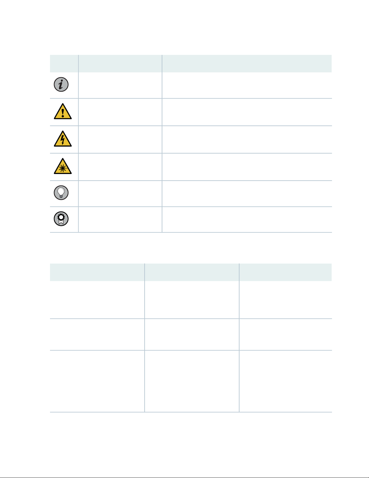
Table 1: Notice Icons
xiv
DescriptionMeaningIcon
Indicates important features or instructions.Informational note
Caution
Indicates a situation that might result in loss of data or hardware
damage.
Alerts you to the risk of personal injury or death.Warning
Alerts you to the risk of personal injury from a laser.Laser warning
Indicates helpful information.Tip
Alerts you to a recommended use or implementation.Best practice
Table 2 on page xiv defines the text and syntax conventions used in this guide.
Table 2: Text and Syntax Conventions
ExamplesDescriptionConvention
Fixed-width text like this
Italic text like this
Represents text that you type.Bold text like this
Represents output that appears on
the terminal screen.
Introduces or emphasizes important
•
new terms.
Identifies guide names.
•
Identifies RFC and Internet draft
•
titles.
To enter configuration mode, type
the configure command:
user@host> configure
user@host> show chassis alarms
No alarms currently active
A policy term is a named structure
•
that defines match conditions and
actions.
Junos OS CLI User Guide
•
RFC 1997, BGP Communities
•
Attribute
Page 15

Table 2: Text and Syntax Conventions (continued)
xv
ExamplesDescriptionConvention
Italic text like this
Text like this
< > (angle brackets)
| (pipe symbol)
Represents variables (options for
which you substitute a value) in
commands or configuration
statements.
Represents names of configuration
statements, commands, files, and
directories; configuration hierarchy
levels; or labels on routing platform
components.
variables.
Indicates a choice between the
mutually exclusive keywords or
variables on either side of the symbol.
The set of choices is often enclosed
in parentheses for clarity.
Configure the machine’s domain
name:
[edit]
root@# set system domain-name
domain-name
To configure a stub area, include
•
the stub statement at the [edit
protocols ospf area area-id]
hierarchy level.
The console port is labeled
•
CONSOLE.
stub <default-metric metric>;Encloses optional keywords or
broadcast | multicast
(string1 | string2 | string3)
# (pound sign)
[ ] (square brackets)
Indention and braces ( { } )
; (semicolon)
GUI Conventions
Indicates a comment specified on the
same line as the configuration
statement to which it applies.
Encloses a variable for which you can
substitute one or more values.
Identifies a level in the configuration
hierarchy.
Identifies a leaf statement at a
configuration hierarchy level.
rsvp { # Required for dynamic MPLS
only
community name members [
community-ids ]
[edit]
routing-options {
static {
route default {
nexthop address;
retain;
}
}
}
Page 16

Table 2: Text and Syntax Conventions (continued)
xvi
ExamplesDescriptionConvention
Bold text like this
> (bold right angle bracket)
Represents graphical user interface
(GUI) items you click or select.
Separates levels in a hierarchy of
menu selections.
In the Logical Interfaces box, select
•
All Interfaces.
To cancel the configuration, click
•
Cancel.
In the configuration editor hierarchy,
select Protocols>Ospf.
Documentation Feedback
We encourage you to provide feedback so that we can improve our documentation. You can use either
of the following methods:
Online feedback system—Click TechLibrary Feedback, on the lower right of any page on the Juniper
•
Networks TechLibrary site, and do one of the following:
Click the thumbs-up icon if the information on the page was helpful to you.
•
Click the thumbs-down icon if the information on the page was not helpful to you or if you have
•
suggestions for improvement, and use the pop-up form to provide feedback.
E-mail—Send your comments to techpubs-comments@juniper.net. Include the document or topic name,
•
URL or page number, and software version (if applicable).
Requesting Technical Support
Technical product support is available through the Juniper Networks Technical Assistance Center (JTAC).
If you are a customer with an active Juniper Care or Partner Support Services support contract, or are
covered under warranty, and need post-sales technical support, you can access our tools and resources
online or open a case with JTAC.
Page 17

JTAC policies—For a complete understanding of our JTAC procedures and policies, review the JTAC User
•
Guide located at https://www.juniper.net/us/en/local/pdf/resource-guides/7100059-en.pdf.
Product warranties—For product warranty information, visit https://www.juniper.net/support/warranty/.
•
JTAC hours of operation—The JTAC centers have resources available 24 hours a day, 7 days a week,
•
365 days a year.
Self-Help Online Tools and Resources
For quick and easy problem resolution, Juniper Networks has designed an online self-service portal called
the Customer Support Center (CSC) that provides you with the following features:
Find CSC offerings: https://www.juniper.net/customers/support/
•
Search for known bugs: https://prsearch.juniper.net/
•
Find product documentation: https://www.juniper.net/documentation/
•
Find solutions and answer questions using our Knowledge Base: https://kb.juniper.net/
•
xvii
Download the latest versions of software and review release notes:
•
https://www.juniper.net/customers/csc/software/
Search technical bulletins for relevant hardware and software notifications:
•
https://kb.juniper.net/InfoCenter/
Join and participate in the Juniper Networks Community Forum:
•
https://www.juniper.net/company/communities/
Create a service request online: https://myjuniper.juniper.net
•
To verify service entitlement by product serial number, use our Serial Number Entitlement (SNE) Tool:
https://entitlementsearch.juniper.net/entitlementsearch/
Creating a Service Request with JTAC
You can create a service request with JTAC on the Web or by telephone.
Visit https://myjuniper.juniper.net.
•
Call 1-888-314-JTAC (1-888-314-5822 toll-free in the USA, Canada, and Mexico).
•
For international or direct-dial options in countries without toll-free numbers, see
https://support.juniper.net/support/requesting-support/.
Page 18

1
CHAPTER
Overview
PTX10003 System Overview | 21
PTX10003 Port Panel | 26
PTX10003 Field-Replaceable Units Panel | 36
PTX10003 Management Panel | 40
PTX10003 Cooling System Description and Airflow | 46
PTX10003 Power System | 50
Page 19

Page 20
PTX10003 System Overview
IN THIS SECTION
Benefits of the PTX10003 | 21
PTX10003-160C | 22
PTX10003-80C | 23
PTX10003 System Architecture | 24
PTX10003 System Software | 24
PTX10003 Fixed-Configuration Router Specifications | 25
21
Occupying only 3 U, the PTX10003 is the industry’s first fixed-configuration core router to support 400 GbE.
The PTX10003 is easy to deploy in space constrained Internet exchange locations, remote central offices,
and embedded peering points throughout the network, including cloud-hosted services. It uniquely addresses
power-constrained environments by providing unprecedented power efficiency of 0.2 watts/Gbps. The
PTX10003 delivers high density 10 GbE, 26 GbE, 40 GbE, 100 GbE, 200 GbE, and 400 GbE and inline
MACsec with no compromise in throughput or latency. Two models with differing capacities are available.
The PTX10003-160C supports 16 Tbps throughput and the PTX10003-80C supports 8 Tbps
throughput—each in a compact 3 U footprint.
TIP: For information about features supported on PTX Series routers, see Feature Explorer.
Benefits of the PTX10003
Juniper Networks ExpressPlus™ Silicon: The PTX10003 is powered by our custom ExpressPlus silicon,
•
providing predictable IP/MPLS packet performance and functionality, along with inline AES-256 MACsec
encryption on all interfaces.
Peering Scale: To match the expanding traffic demands, the PTX10003 delivers a peering scale of up to
•
3 million Forwarding Information Base (FIB) routes and up to 20 million Routing Information Base (RIB)
routes, also known as forwarding and routing tables, respectively.
QSFP-DD: The PTX10003 supports universal multi-rate QSFP-DD optics, quadrupling aggregate switch
•
bandwidth while maintaining port density. QSFP-DD supports continuing growth in network bandwidth
Page 21
demand and data center traffic. Systems designed with QSFP-DD are backwards compatible, allowing
them to support existing QSFP optical modules and provide flexibility for end users and system designers.
Juniper Networks Junos OS Evolved: The PTX10003 operates on Junos OS Evolved, Juniper Networks
•
next-generation Junos OS. Junos OS Evolved has the same CLI user interface, the same code base for
applications and features, and the same management and automation tools as Junos OS. However, the
Junos OS Evolved infrastructure is entirely modernized, delivering the high availability, portability, faster
innovation, and simplified upgrades you need.
Interoperability: The PTX10003 provides seamless interoperability with existing Juniper routing
•
deployments.
PTX10003-160C
The PTX10003-160C scales to 16 Tbps in a single chassis. Operating in a fixed core router configuration,
the PTX10003-160C has flexible interface configuration options, with universal multirate QSFP-DD for
100 GbE/400 GbE/FlexE to support 320 (QSFP +) 10 GbE ports, 80 (QSFP +) 40 GbE ports, 160 (QSFP28)
100 GbE ports, 64 (QSFP28-DD) 200 GbE ports, or 32 (QSFP56-DD) 400 GbE ports. Refer to
Figure 1 on page 22.
22
Figure 1: PTX10003-160C Port Panel
NOTE: 200 Gbps and 400 Gbps data rates are supported on Juniper Junos OS Evolved release
19.3R1 and later.
The FRU panel for the PTX10003-160C has four power supplies, five fan modules, two chassis grounding
points, and an ESD grounding point. Refer to Figure 2 on page 23.
Page 22
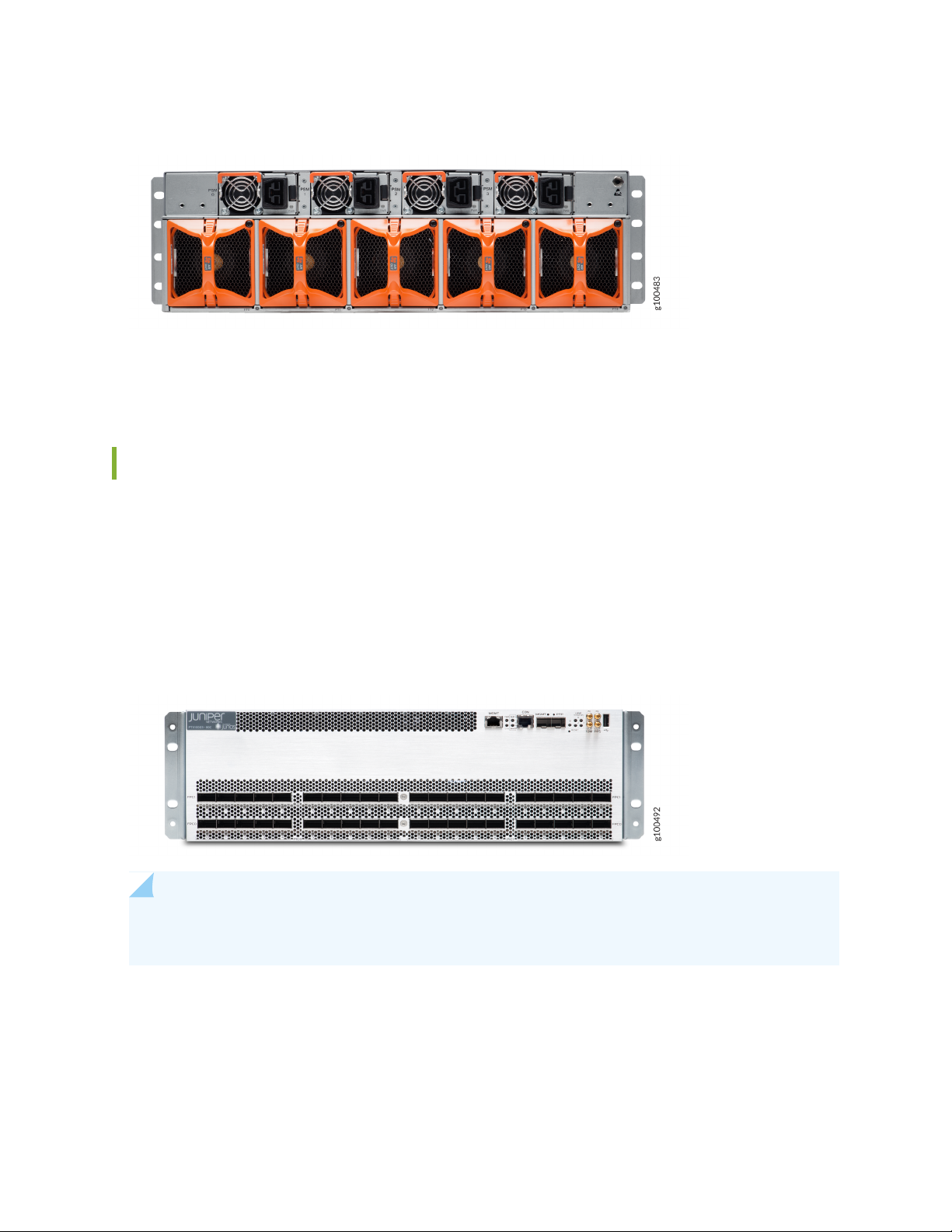
Figure 2: PTX10003-160C FRU Panel (AC/HVDC Power Supplies)
For more information about the components on the FRU panel, see “PTX10003 Field-Replaceable Units
Panel” on page 36.
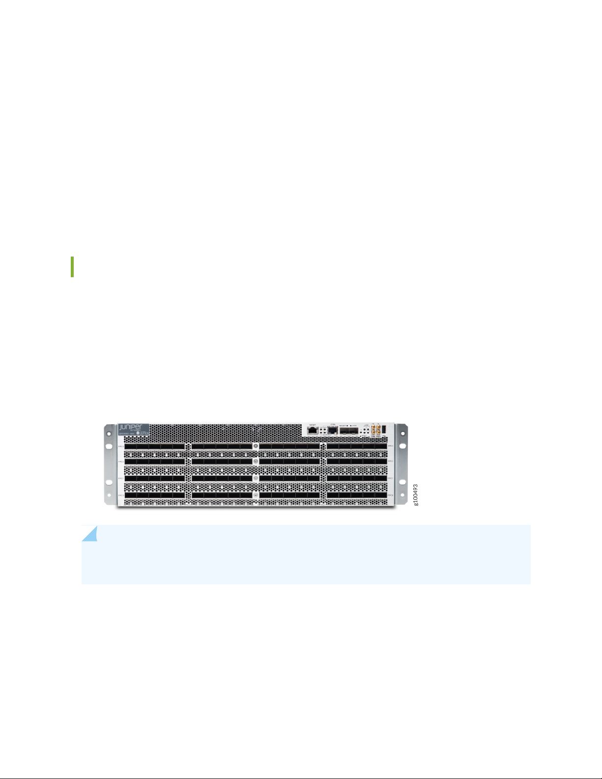
PTX10003-80C
23
The PTX10003-80C scales to 8 Tbps in a single chassis. Operating in a fixed core router configuration,
the PTX10003-80C has flexible interface configuration options, with universal multirate QSFP-DD for
100GE/400GE/FlexE to support 160 (QSFP +) 10 GbE ports, 40 (QSFP +) 40 GbE ports, 80 (QSFP28)
100 GbE ports, 32 (QSFP28-DD) 200 GbE ports, or 16 (QSFP56-DD) 400 GbE ports. Refer to
Figure 3 on page 23.
Figure 3: PTX10003-80C
NOTE: 200 Gbps and 400 Gbps data rates are supported on Juniper Junos OS Evolved release
19.3R1 and later.
The FRU panel for the PTX10003-80C has two power supplies, three fan modules, two chassis grounding
points, and an ESD grounding point. Refer to Figure 4 on page 24.
Page 23
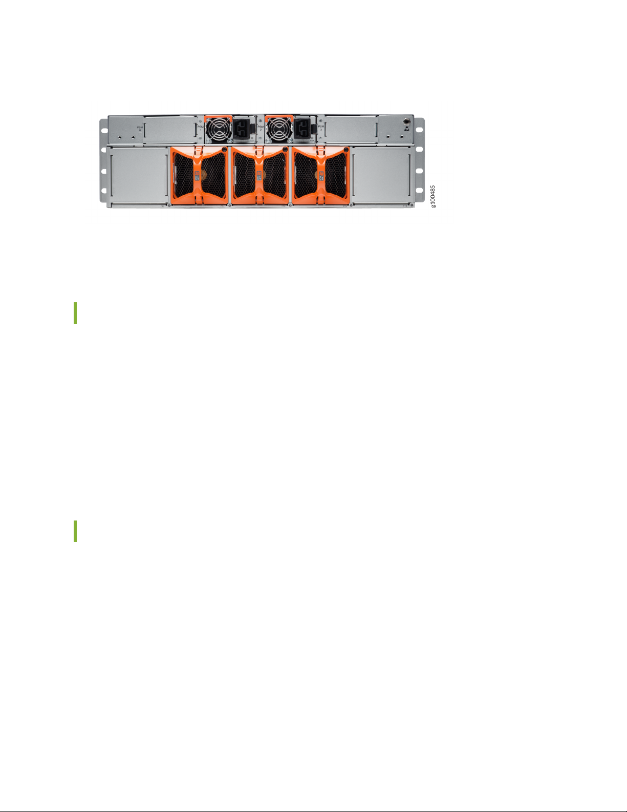
Figure 4: PTX10003-80C FRU Panel
For more information about the components on the FRU panel, see “PTX10003 Field-Replaceable Units
Panel” on page 36.
PTX10003 System Architecture
24
Using Juniper Networks custom ExpressPlus silicon, the PTX10003 system architecture cleanly separates
control operations from packet forwarding operations. This design eliminates processing and traffic
bottlenecks, permitting the PTX10003 to achieve high performance.
Control operations are performed by the Routing Engine, which runs Junos OS Evolved. The Routing
Engine handles routing protocols, traffic engineering, policy, policing, monitoring, and configuration
management. Junos OS Evolved is pre-installed on the PTX10003 internal solid-state drives (SSDs).
Forwarding operations are performed by the Packet Forwarding Engines (PFE) to deliver inline MACsec
on all ports and high density high density 10 GbE, 40 GbE, 100 GbE, 200 GbE, and 400 GbE.
PTX10003 System Software
The PTX10003 runs Junos OS Evolved, which provides Layer 2 and Layer 3 switching, routing, and security
services. Junos OS Evolved runs natively on Linux, giving it direct access to all the Linux utilities and
operations. It is designed to be modular, allowing for upgrades to be done on a component-by-component
basis without a system reboot. Only those components changed are restarted. Junos OS Evolved is easily
portable and minimal work is required to make it work on any platform. It has the same CLI user interface,
the same code base for applications and features, and the same management and automation tools as
Junos OS. However, the Junos OS Evolved infrastructure is entirely modernized, giving you the high
availability, portability, faster innovation, and simplified upgrades you need. Junos OS Evolved software
is installed on the PTX10003 200 GB internal NAND solid state flash drive.
For information about which features are supported on PTX Series devices, see Feature Explorer.
Page 24

PTX10003 Fixed-Configuration Router Specifications
Table 3: PTX10003 Specifications
PTX10003-80CPTX10003-160CHardware
8 Tbps16 TbpsSystem Throughput
Up to 5.3 BppsUp to 10.6 BppsForwarding Capacity
25
Dimension (WxHxD)
17.4 x 5.25 x 31 in (44.2 x 13.3 x 78.7
cm)
17.4 x 5.25 x 31 in (44.2 x 13.3 x 78.7
cm)
3 U3 URack units
88 lb (40 kg)110 lb (50 kg)Weight
Intel Broadwell CPU with 12 CoresIntel Broadwell CPU with 12 CoresCPU
64 Gigabit SDRAM64 Gigabit SDRAMRAM
200 GBx2200 GBx2SSD
~2500 W (AC,HVDC), 8525 BTU/hr~4000 W (AC.HVDC), 13640 BTU/hrMaximum power draw
~1600 W (AC,HVDC), 5456 BTU/hr~3100W (AC,HVDC), 10571 BTU/hrTypical power draw
2x3000 watts (AC/HVDC)4x3000 watts (AC/HVDC)Power supply
3 hot-swappable fans5 hot-swappable fansCooling (front-to-back fan)
64 Gb128 GbPacket buffer
2.5 μs within PFE, 5 μs between PFEs2.5 μs within PFE, 5 μs between PFEsLatency
0.20.2Power Efficiency (watts/Gbps)
24Power Supply Slots
2.5 KW4 KWPower Rating AC
2.5 KW4 KWPower Rating HVDC
Page 25

PTX10003 Port Panel
IN THIS SECTION
PTX10003-160C Port Panel | 26
PTX10003-80C Port Panel | 27
Understanding QSFP-DD Interfaces and Configurations | 28
Allowable QSFP-DD Interface Configurations for the PTX10003-160C | 29
Allowable QSFP-DD Interface Configurations for the PTX10003-80C | 30
Examples of PTX10003 QSFP-DD Configurations | 30
PTX10003 Port LEDs | 34
Channelizing Interfaces on PTX10003 Routers with Junos OS Evolved | 35
26
PTX10003-160C Port Panel
Operating in a fixed core router configuration, the PTX10003-160C features flexible interface configuration
options with universal multi-rate double-density Quad Small Form-factor Pluggable (QSFP-DD) optics.
The port panel has 80 optical interfaces which support data rates of 10 Gbps, 25 Gbps, 40 Gbps, 100 Gbps,
200 Gbps, and 400 Gbps. Each of the 16 Juniper Networks 1 Tbps ExpressPlus ASICs in the PTX10003-160C
connect to a group of five QSFP-DD ports. You can configure different data rates for each port group as
long as the total throughput for the group does not exceed 1 Tbps. For more details, see “Understanding
QSFP-DD Interfaces and Configurations” on page 28.
Figure 5 on page 27 illustrates the PTX10003-160C port panel.
Page 26
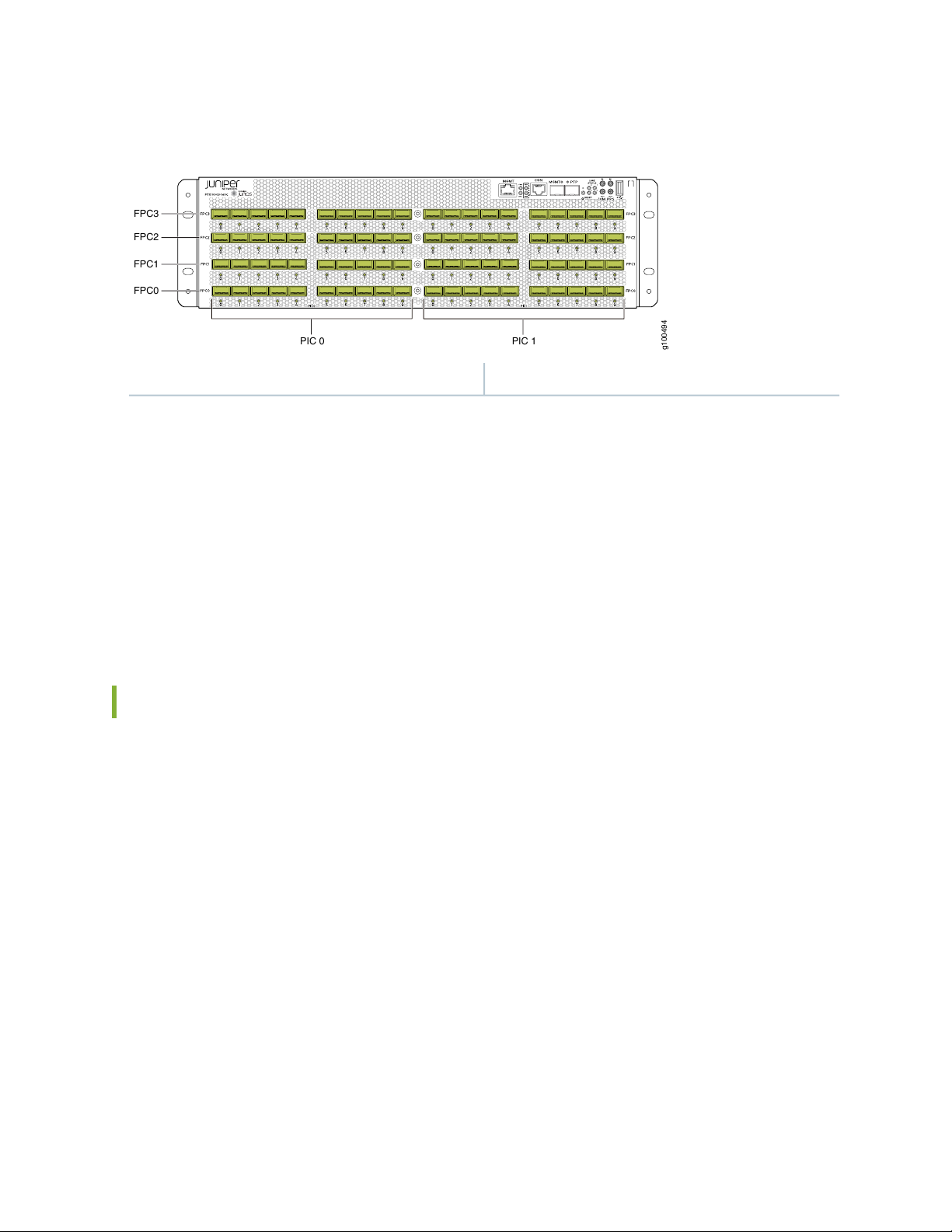
Figure 5: PTX10003-160C Port Panel
g100494
021
3
B
PIC 0
FPC3
FPC2
FPC1
FPC0
PIC 1
1—80 optical interfaces with 80 port LEDs
As illustrated in Figure 5 on page 27, the interfaces for the PTX10003-160C are divided into logical FPCs,
logical PICs, and physical optical ports as follows:
FPCs: The PTX10003-160C has four FPCs, numbered 0, 1, 2, and 3 from the bottom up in the chassis.
•
PICs: Each FPC has two logical PICs, numbered 0 and 1 from left to right.
•
27
Ports:: Each PIC controls 10 QSFP-DD optical interfaces, numbered 0 through 9 from left to right.
•
The 10 QSFP-DD optical interfaces are divided into two groups of five ports.
•
Each port group is controlled by two PFEs.
•
PTX10003-80C Port Panel
Operating in a fixed core router configuration, the PTX10003-80C features flexible interface configuration
options with universal multi-rate double-density Quad Small Form-factor Pluggable (QSFP-DD) optics.
The port panel has 40 optical interfaces which support data rates of 10 Gbps, 25 Gbps, 40 Gbps, 100 Gbps,
200 Gbps, and 400 Gbps. Each of the eight Juniper Networks 1 Tbps ExpressPlus ASICs in the
PTX10003-80C connect to a group of five QSFP-DD ports. You can configure different data rates for each
port group as long as the total throughput for the group does not exceed 1 Tbps. See “Understanding
QSFP-DD Interfaces and Configurations” on page 28 for more details.
Figure 6 on page 28 illustrates the PTX10003-80C port panel.
Page 27
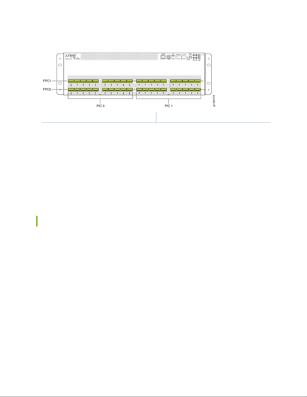
Figure 6: PTX10003-80C Port Panel
g100474
021
3
B
PIC 0
PIC 1
FPC1
FPC0
1—40 optical interfaces with 40 port LEDs
As illustrated in Figure 6 on page 28, the interfaces for the PTX10003-80C are divided into logical FPCs,
logical PICs, and physical optical ports as follows:
FPCs: The PTX10003-80C has two FPCs, numbered 0 and 1 from the bottom up in the chassis.
•
PICs: Each FPC has two logical PICs, numbered 0 and 1 from left to right.
•
28
Ports:: Each PIC controls 10 QSFP-DD optical interfaces, numbered 0 through 9 from left to right.
•
The 10 QSFP-DD optical interfaces are divided into two groups of five ports.
•
Each port group is controlled by two Packet Forwarding Engines (PFE).
•
Understanding QSFP-DD Interfaces and Configurations
Each Juniper Networks 1 Tbps ExpressPlus ASIC contains two logically independent PFEs which can
provide 400 Gbps throughput. Each QSFP-DD port group is controlled by two PFEs with the middle
QSFP-DD interface (port 2 and port 7) being shared by the PFEs.
Any port can be used as a 100-Gigabit Ethernet interface, 40-Gigabit Ethernet interface, or 10-Gigabit
Ethernet interface. You choose the speed by plugging in the appropriate optical transceiver. You can also
channelize the 100 Gbps and 200 Gbps ports to create multiple independent 25 Gbps interfaces. You can
channelize the 40 Gbps ports to create multiple independent 10 Gbps ports. See Channelizing Interfaces
on PTX10003 Routers for more details.
Given the design of the Juniper Networks ExpressPlus ASIC and chassis level thermal considerations, there
are certain limitations for some QSFP-DD interfaces and configurations. Each QSFP-DD port group can
be configured to achieve the maximum 1 Tbps throughput with the following limitations:
Page 28

Only the interfaces at the outer edge of each QSFP-DD group can be configured for 1x400 Gbps (using
•
QSFP56-DD optics).
The middle QSFP-DD port that is shared across two PFE’s (port 2 and port 7) cannot support a data rate
•
of 1x200 Gbps. These ports can only support 2x100 Gbps (QSFP28-DD).
The highest QSFP-DD data rate that can be used across all QSFP-DD groups is 200 Gbps (2x100 Gbps).
•
This provides 16 Tbps throughput for the PTX10003-160C, and 8 Tbps throughput for the
PTX10003-80C.
Aside from running all interfaces with 2x100 Gbps optics, there are other ways to attain the maximum
•
system throughput. The 400 Gbps optics can be used in combination with 100 Gbps optics and 200 Gbps
optics as shown in the following examples.
Allowable QSFP-DD Interface Configurations for the PTX10003-160C
Assuming the limitations described previously, Table 4 on page 29 lists the allowable interface configurations
for the PTX10003-160C.
29
Table 4: PTX10003-160C Port Density per Optical Interface
QSFP2880
4x25 Gbps
Maximum Number of InterfacesData RateQSFP TransceiverNumber of Ports
320 10 Gbps4x10 GbpsQSFP+80
80 40 Gbps1x40 Gbps
80 100 Gbps1x100 Gbps or
64 200 Gbps1x200 Gbps or 8x25GbpsQSFP28-DD64
160 100 Gbps2x100 Gbps80
32 400 Gbps1x400 GbpsQSFP56-DD32
128 100 Gbps4x100 Gbps
Page 29

Allowable QSFP-DD Interface Configurations for the PTX10003-80C
Assuming the limitations described previously, Table 5 on page 30 lists the allowable interface configurations
for the PTX10003-80C.
Table 5: PTX10003-80C Port Density per Optical Interface
Maximum Number of InterfacesData RateQSFP TransceiverNumber of Ports
160 10 Gbps4x10 GbpsQSFP+40
40 40 Gbps1x40 Gbps
30
QSFP2840
4x25 Gbps
QSFP28-DD32
8x25 Gbps
40 100 Gbps1x100 Gbps or
32 200 Gbps1x200 Gbps or
80 100 Gbps2x100 Gbps40
16 400 Gbps1x400 GbpsQSFP56-DD16
64 100 Gbps4x100 Gbps
Examples of PTX10003 QSFP-DD Configurations
By default, all PTX10003 QSFP-DD interfaces are configured for a data rate of 2x100 Gbps. You can
change the port configuration to achieve different throughput using the following Junos OS Evolved
command:
set chassis fpc slot-number pic pic-number port port-number number-of-subports [1 | 2 | 4 |8] speed [10G
| 25G | 40G | 100G | 200G |400G] command.
For example, to configure the second port in the first port group as a 4x10 Gbps interface, use the set
chassis fpc 0 pic 0 port 1 number-of-subports 4 speed 10g command. After you commit this configuration,
the second port in PIC 0 will operate at 4x10 Gbps.
Page 30
NOTE: When a port speed and sub-port-number are configured, the configured values override
g100499
1 x 400G
QSFP56-DD
4 x 10G
QSFP+
1 x 400G
QSFP56-DD
0 1 2 3 4
4 x 10G
QSFP+
the default port speed for the transceiver. If you try to configure a port speed that is not supported
by the transceiver, the port will be disabled. If there isn’t a port speed configured on a valid optical
port, the PTX10003 uses a default port speed of 2x100 Gbps. Also, if number-of-subports is not
configured, a 1x 40G | 100G |200G |400G] data rate is assumed. A 1x10G sub-port is not supported.
Example: Using Network Ports as 10 Gbps or 40 Gbps Ethernet Interfaces
With QSFP+ transceivers, you can configure 10 Gbps or 40 Gbps interfaces on any port. To attain the
maximum 1 Tbps throughput for a port group, you can configure the 10 Gbps and 40 Gbps ports with
combinations of 1x100 Gbps, 2x100 Gbps, and 400 Gbps, data rates. Refer to Table 6 on page 31.
31
NOTE: 1x10 Gbps and 2x10 Gbps are not supported.
NOTE: Only the ports at the outer edge of each group can be configured for 1x400 Gbps (using
QSFP56-DD transceivers).
Table 6: Using Network Ports as 10 Gbps or 40 Gbps Ethernet Interfaces
Maximum Number of
QSFP
TransceiverData Rate
Allowable Port
Numbers
Ports
(PTX10003-160C)
Maximum Number of
Ports (PTX10003-80C)
1603200-9QSFP+4x10 Gbps
40800-9QSFP+1x40 Gbps
Page 31

Example: Using Network Ports as 100 Gbps Ethernet Interfaces
g100498
2 x 100G
QSFP-DD
2 x 100G
QSFP-DD
2 x 100G
QSFP-DD
0 1 2 3 4
2 x 100G
QSFP-DD
2 x 100G
QSFP-DD
g100497
1 x 200G
QSFP56-DD
2 x 100G
QSFP28-DD
1 x 200G
QSFP56-DD
0 1 2 3 4
1 x 200G
QSFP56-DD
1 x 200G
QSFP56-DD
With QSFP28 and QSFP28-DD transceivers, you can configure a 2x100 Gbps data rate on any port. This
is the default port configuration. To attain the maximum 1 Tbps throughput for a port group using 100 Gbps
interfaces, you can configure combinations of 1x100 Gbps, 2x100 Gbps, and 4x100 Gbps data rates. Refer
to Table 7 on page 32.
Table 7: Using Network Ports as 100 Gbps Interfaces
32
Maximum Number
of Ports
(PTX10003-80C)
Allowable Port
NumbersQSFP TransceiverData Rate
Maximum Number of
Ports
(PTX10003-160C)
40800-9QSFP281x100 Gbps
801600-9QSFP28-DD2x100 Gbps
641280, 4, 5, 9QSFP56-DD4x100 Gbps
Example: Using Network Ports as 200 Gbps Ethernet Interfaces
With QSFP28-DD transceivers, you can configure select ports in each port group as a 1x200 Gbps Ethernet
interface. To attain the maximum 1 Tbps throughput for a port group, you can configure combinations of
1x400 Gbps, 1x100 Gbps, 2x100 Gbps, and 1x200 Gbps data rates. Refer to Table 8 on page 33.
NOTE: The center port in each port group (port 2 and port 7) cannot support 1x200 Gbps. To
configure a 200 Gbps data rate for those ports, you’ll need to configure them as 2x100 Gbps.
Page 32

Table 8: Using Network Ports as 200 Gbps Interfaces
g100584
1 x 400G
QSFP56-DD
1 x 100G
QSFP28
1 x 400G
QSFP56-DD
0 1 2 3 4
1 x 100G
QSFP28
g100582
PIC 0
PIC 1
FPC1
FPC0
400G
100G
400G
100G
400G
100G
400G
100G
400G
100G
400G
100G
400G
100G
400G
100G
400G
100G
400G
100G
400G
100G
400G
100G
400G
100G
400G
100G
400G
100G
400G
100G
33
Maximum Number of
Ports
(PTX10003-80C)
Allowable Port
NumbersQSFP TransceiverData Rate
Maximum Number of
Ports
(PTX10003-160C)
32640, 1, 3, 4, 5, 6, 8, 9QSFP28-DD1x200 Gbps
801600-9QSFP28-DD2x100 Gbps
NOTE: 200 Gbps data rates are supported on Juniper Junos OS Evolved release 19.3R1 and later.
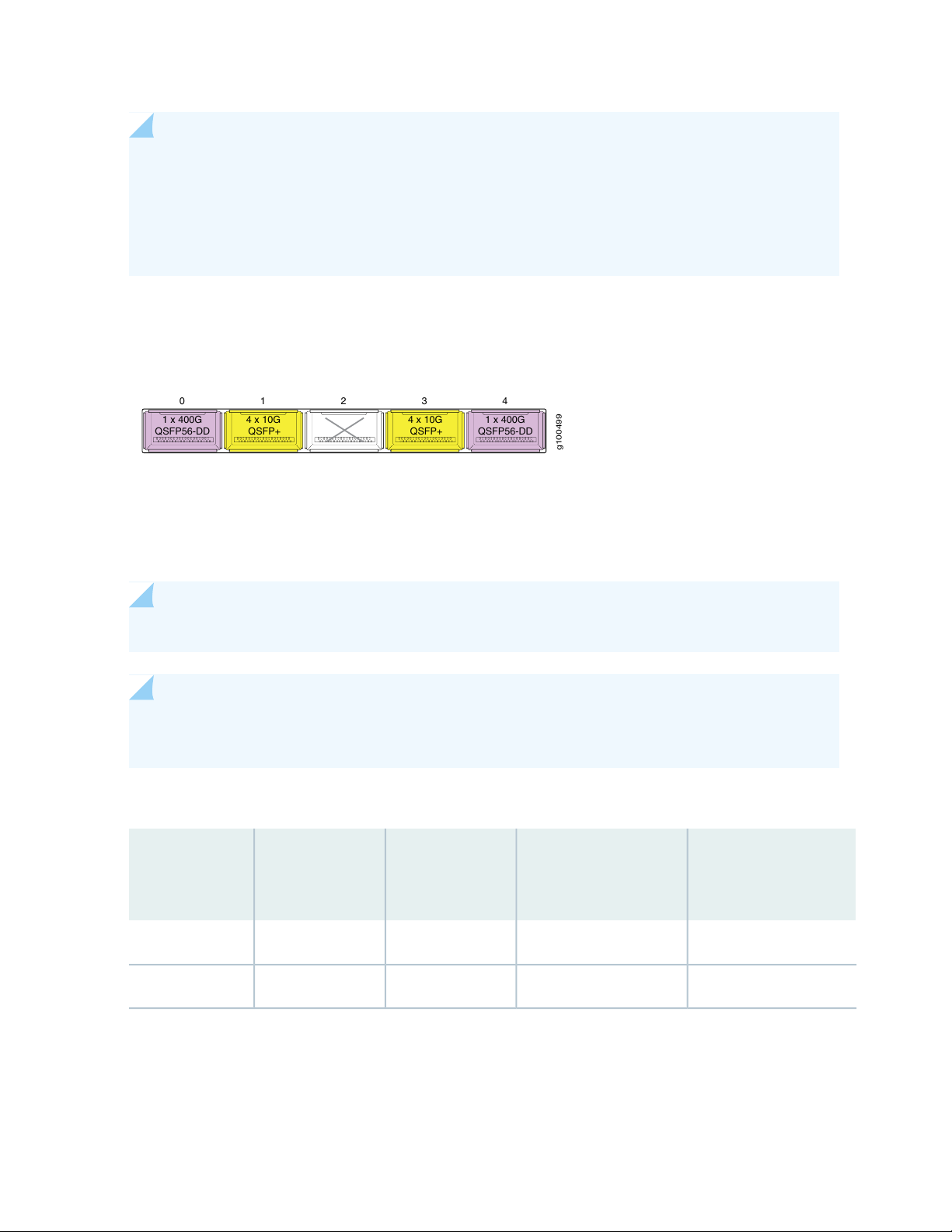
Example: Using Network Ports as 1x400 Gbps Ethernet Interfaces
With QSFP56-DD transceivers, you can configure a data rate of 1x400 Gbps on the two outer ports in a
port group. To attain the maximum 1 Tbps throughput, you can configure combinations of 1x400 Gbps,
1x100 Gbps, 2x100 Gbps, and 1x200 Gbps data rates with the following limitations:
Only the ports at the outer edge of each group can be configured for 1x400 Gbps (using QSFP56-DD
•
transceivers).
When ports 0, 4, 5, 9 are configured as 1x400 Gbps, the center ports 2 and 7 must be blank.
•
When configuring a port for 1x200 Gbps, port 1, 3, 6 and 8 must be blank or configured as 1x100 Gbps.
•
Page 33

Table 9: Using Network Ports as 400 Gbps Interfaces
34
Maximum Number
of Ports
(PTX10003-80C)
16320, 4, 5, 9QSFP56-DD1x400 Gbps
641280, 4, 5, 9QSFP56-DD4x100 Gbps
801600-9QSFP28-DD2x100 Gbps
Allowable Port
NumbersQSFP TransceiverData Rate
Maximum Number of
Ports
(PTX10003-160C)
NOTE: 400 Gbps data rates are supported in Juniper Junos OS Evolved release 19.3R1 and later.
PTX10003 Port LEDs
Each PTX10003 port uses a single bi-colored LED to indicate link status and activity. See
Table 10 on page 34 for how to interpret the port LEDs.
NOTE: After you insert an optical transceiver, the LINK UP LED flashes red and green during the
first 60 seconds. This means the link is unstable. It may take up to 60 seconds for the LED to stop
flashing.
Table 10: Network Port LEDs on a PTX10003
DescriptionStateColor
Off—
On steadilyAmber
The transceiver is not present or loopback configuration is
present.
A link is established and all channels are up.On steadilyGreen
One or more channels are up. However, at least one channel
has activity, but not all connections are active.
All channels are down.On steadilyRed
Page 34

Channelizing Interfaces on PTX10003 Routers with Junos OS Evolved
PTX10003 Packet Transport Routers feature flexible interface configuration options with universal multi-rate
double-density Quad Small Form-factor Pluggable (QSFP-DD) optics. The PTX10003-80C port panel has
40 physical ports and the PTX10003-160C port panel has 80 physical ports. The physical ports are in
groups of five QSFP-DD ports. You can configure different data rates for each port group as long as the
total throughput for the group does not exceed 1 Tbps. Any port can be used as a 100-Gigabit Ethernet
interface, 40-Gigabit Ethernet interface, or 10-Gigabit Ethernet interface. You choose the speed by plugging
in the appropriate transceiver.
NOTE: The center port in each port group (port 2 and port 7) cannot support 1x200 Gbps. To
configure a 200 Gbps data rate for those ports, you’ll need to configure them as 2x100 Gbps. For
more details, see “Understanding QSFP-DD Interfaces and Configurations” on page 28.
You can channelize the Gigabit Ethernet interfaces on PTX10003 routers to create multiple independent
Gigabit Ethernet interfaces and then use breakout cables to connect the channelized ports to other servers,
storage devices, and routers. Here’s the allowable channelization configurations for the optical transceivers
supported by the PTX10003:
35
Channelization OptionsNative Port SpeedsQSFP Transceiver
QSFP28-DD
2x100 Gbps
QSFP+
4x10 Gbps
8x25 Gbps1x200 Gbps
4x25 Gbps1x100 GbpsQSFP28
4x10 Gbps1x40 Gbps
NOTE: For more details about supported transceivers and cable specifications, see the PTX10003
Packet Transport Router Hardware Guide .
By default, all PTX10003 QSFP-DD interfaces are configured for a data rate of 2x100 Gbps. The interface
names appear in the et-fpc/pic/port:channel format.
The port speed can be configured at the PIC-level. To view the port speed capability of a logical PIC, issue
the show chassis pic fpc-slot slot-number pic-slot slot-number command.
Page 35

For details on how to channelize a port, see Channelizing Interfaces on PTX10003 Routers.
SEE ALSO
number-of-sub-ports
speed (Ethernet)
fpc
pic
PTX10003 Field-Replaceable Units Panel
36
IN THIS SECTION
PTX10003-160C FRU Panel | 37
PTX10003-80C FRU Panel | 39
Page 36

The PTX10003 field-replaceable units (FRU) panel contains fan modules, power supply modules, two
g100451
21 1 3
4
grounding points, and an ESD grounding point. The PTX10003 FRUs are hot-removable and
hot-insertable—you can remove and replace them without powering off the PTX10003 or disrupting the
routing function.
NOTE: If you have a Juniper Care service contract, register any addition, change, or upgrade of
hardware components at https://www.juniper.net/customers/support/tools/updateinstallbase/.
Failure to do so can result in significant delays if you need replacement parts. This note does not
apply if you replace existing components with the same type of component.
PTX10003-160C FRU Panel
The FRU panel for the PTX10003-160C has four power supplies, five fan modules, two chassis grounding
points, and an ESD grounding point. Refer toFigure 7 on page 37 (AC/HVDC power supplies) and
Figure 8 on page 38 (DC power supplies).
37
Figure 7: PTX10003-160C FRU Panel with AC/HVDC Power Supplies
3—1— ESD grounding pointChassis grounding points
4—2— Fan modules (5)Power supplies (4)
Page 37

Figure 8: PTX0003-160C FRU Panel with DC Power Supplies
g100452
21 1 3
4
3—1— ESD grounding pointChassis grounding points
4—2— Fan modules (5)Power supplies (4)
Table 11 on page 38 lists the component part numbers for PTX10003-160C FRUs.
38
Table 11: List of PTX10003-160C FRUs
PTX10003-160C-ACPTX10003-160C Base
System (AC)
PTX10003-160C-DCPTX10003-160C Base
System (DC)
JNP10003-160C-CHASPTX10003-160C Chassis
Spare
JNP-3000W-AC-AFOAC Power Supply
DescriptionModel NumberComponent
PTX10003-160C base system with 160 100 GbE ports
or 32 400 GbE ports, 4 3000 W AC power supplies, 4
power cables, and 5 fan trays, with standard tier
right-to-use license.
PTX10003-160C base system with 160 100 GbE ports
or 32 400 GbE ports, 4 3000 W DC power supplies, and
5 fan trays, with standard tier right-to-use license
JNP10003-160C spare chassis with 160 100 GbE ports
or 32 400 GbE ports.
Fan tray for 3 RU 8 T and 16 T fixed platforms.JNP10003-FANFan Tray
AC power supply for JNP10003-160C and JNP10003-80C
fixed platforms.
JNP-3000W-DC-AFODC Power Supply
DC power supply for JNP10003-160C and JNP10003-80C
fixed platforms
Page 38

PTX10003-80C FRU Panel
g100261
2
1
1 3
4
g100262
1
1 3
4
2
The FRU panel for the PTX10003-80C has two power supplies, three fan modules, two chassis grounding
points, and an ESD grounding point. Refer toFigure 9 on page 39 (AC/HVDC power supplies) and
Figure 10 on page 39(DC power supplies).
Figure 9: PTX10003-80C with AC/HVDC Power Supplies
39
3—1— ESD grounding pointChassis grounding points
4—2— Fan modules (3)Power supplies (2)
Figure 10: PTX10003-80C with DC Power Supplies
3—1— ESD grounding pointChassis grounding points
4—2— Fan modules (3)Power supplies (2)
Table 12 on page 40 lists the component part numbers for PTX10003-80C FRUs.
Page 39

Table 12: List of PTX10003-80C FRUs
40
DescriptionModel NumberComponent
(AC)
System (DC)
(Spare)
PTX10003-80C-ACPTX10003-80 Base System
PTX10003-80C-DCPTX10003-80C Base
JNP10003-80C-CHASPTX10003-80C Chassis
JNP-3000W-AC-AFOAC Power Supply
JNP-3000W-DC-AFODC Power Supply
PTX10003-80C base system with 80 100 GbE ports or 16
400 GbE ports, 2 3000 W AC power supplies, 2 power
cables, and 3 fan trays, with standard tier right-to-use
license.
PTX10003-80C base system with 80 100 GbE ports or 16
400 GbE ports, 2 3000 W DC power supplies, and 3 fan
trays, with standard tier right-to-use license.
JNP10003-80C spare chassis with 80 100 GbE ports or
16 400 GbE ports.
Fan tray for 3 RU 8T and 16T fixed platforms.JNP10003-FANFan Tray
AC power supply for JNP10003-160C and JNP10003-80C
fixed platforms.
DC power supply for JNP10003-160C and JNP10003-80C
fixed platforms.
PTX10003 Management Panel
IN THIS SECTION
PTX10003 Management Panel Components | 41
PTX10003 Management Panel LEDs | 42
The PTX10003-8T management panel is in the upper right corner of the port panel (see
Figure 11 on page 41).
Page 40

Figure 11: PTX10003-8T Port Panel and Management Panel
g100260
LANE
STATUS
021
3
B
1
2
2—1— Port panelManagement panel
PTX10003 Management Panel Components
41
You manage the PTX10003 by using the Junos OS Evolved software CLI, which is accessible through the
console and out-of-band management ports on the management panel. The management panel, located
in the upper right corner of the port panel, has system status LEDs that alert you to minor and major alarms,
and other issues with the router. It also has external clock synchronization ports and a USB port to support
software installation and recovery. Figure 12 on page 42 shows the management panel in detail.
Page 41

Figure 12: PTX10003 Management Panel Components
LANE
STATUS
021
3
B
1 2 3 5 6 74 8 9
g100268
10
42
6—1— Beacon LEDRJ-45 Ethernet management port(MGMT)
Power (PWR) Status (STA) and alarm LEDs (MJR=
major alert; MNR=minor alert)
7—2— Four LANE STATUS LEDs numbered 0, 1, 2, 3 for
lane identification of the QSFP channel. The lane ID
LEDs work in conjunction with the activity LEDs that
appear beneath the optics. These optics can support
up to four independent lanes. Since there is only one
LED per QSFP, the lane ID LEDs indicate which
physical QSFP lane corresponds to the LED indicator
that is currently active.
RJ-45 console UART (CON) port. An optional GPS
Time of Day (TOD) is also supported.
8—3— Four co-axial input/output (IN/OUT SMB connectors
for external 1PPS and 5MHz/10MHz simultaneous
I/O bi-directional timing. BITS is not supported.
9—4— USB 2.0 port for connection to the CPUSFP (MGMT) port for 1G system management
10—5— Reset (RESET) push button for resetting the CPUSFP (PTP) port for an IEEE 1588 PTP timing source
PTX10003 Management Panel LEDs
Table 13 on page 42 describes the management panel LEDs on the PTX10003.
Table 13: PTX10003 Management Panel LEDs
Port LED MGMT
DefinitionColor/StateLED Name
Link up, no activityOffRJ-45 10/100/1000 Management
Link up, activityYellow/Blinking
Power is okGreen/OnPower LEDs PWR
Power faultYellow/Blinking
OfflineOff
Page 42

Table 13: PTX10003 Management Panel LEDs (continued)
MGMT
43
DefinitionColor/StateLED Name
Link up, no activityGreenSFP Optic Management Port LED
Link up, activityGreen/Blinking
Link downOff
Link up, no activityGreenPTP Port LED PTP
Link, activityGreen/Blinking
Link downOff
Alarm is activeRed/OnAlarm
MJR
MNR
Green/off, 2x2 LED matrixLANE STATUS
No alarmOff
Alarm is activeYellow/OnAlarm LEDs
No alarmOff
Used as chassis locatorBlue/offBeacon (B)
Indicates which lane of optics
corresponds to LED traffic indicator
beneath optics. Upper left corner LED
corresponds to lane 0, proceeding
clock wise – lane 1,2,3
For power and temperature alarms, use the show chassis environment fpc operational mode command
to get detailed information on the internal state of the chassis. For example:
user@device> show chassis environment fpc
FPC 0 status:
State Online
Temperature 51 degrees C / 123 degrees F
Voltage:
PE0 VDD Core 0.9V 949 mV
PE0 AVDD 1.0V 1000 mV
Page 43

PE0 HMC VDD 0.9V 897 mV
PE0 HMC AVDD 1.2V 1197 mV
PE01 HMC VDD 1.2V 1197 mV
PE1 VDD Core 0.9V 949 mV
PE1 AVDD Core 1.0V 999 mV
PE1 HMC VDD 0.9V 899 mV
PE1 HMC AVDD 1.2V 1197 mV
PE2 VDD Core 0.9V 950 mV
PE2 AVDD Core 1.0V 999 mV
PE2 HMC VDD 0.9V 897 mV
PE2 HMC AVDD 1.2V 1197 mV
PE23 HMC AVDD 1.2V 1197 mV
PE3 VDD Core 0.9V 949 mV
PE3 AVDD Core 1.0V 999 mV
PE3 HMC VDD 0.9V 899 mV
PE3 HMC AVDD 1.2V 1200 mV
PE4 VDD Core 0.9V 949 mV
PE4 AVDD Core 1.0V 999 mV
PE4 HMC VDD 0.9V 899 mV
PE4 HMC AVDD 1.2V 1197 mV
PE45 HMC AVDD 1.2V 1197 mV
PE5 VDD Core 0.9V 949 mV
PE5 AVDD Core 1.0V 1000 mV
PE5 HMC VDD 0.9V 899 mV
PE5 HMC AVDD 1.2V 1200 mV
XMB VDD 3.3V 3316 mV
MAIN VDD 3.3V 3298 mV
RT VDD 1.0V 999 mV
MAIN VDD 2.5V 2502 mV
MAIN PFE 1.5V 1502 mV
PE6 VDD Core 0.9V 949 mV
PE6 AVDD 1.0V 1000 mV
PE6 HMC VDD 0.9V 897 mV
PE6 HMC AVDD 1.2V 1204 mV
PE67 HMC VDD 1.2V 1197 mV
PE7 VDD Core 0.9V 949 mV
PE7 AVDD Core 1.0V 999 mV
PE7 HMC VDD 0.9V 897 mV
PE7 HMC AVDD 1.2V 1197 mV
PE8 VDD Core 0.9V 949 mV
PE8 AVDD Core 1.0V 999 mV
PE8 HMC VDD 0.9V 897 mV
PE8 HMC AVDD 1.2V 1200 mV
PE78 HMC AVDD 1.2V 1197 mV
44
Page 44

PE9 VDD Core 0.9V 950 mV
PE9 AVDD Core 1.0V 999 mV
PE9 HMC VDD 0.9V 897 mV
PE9 HMC AVDD 1.2V 1200 mV
PE10 VDD Core 0.9V 949 mV
PE10 AVDD Core 1.0V 999 mV
PE10 HMC VDD 0.9V 899 mV
PE10 HMC AVDD 1.2V 1200 mV
PE910 HMC AVDD 1.2V 1200 mV
PE11 VDD Core 0.9V 950 mV
PE11 AVDD Core 1.0V 999 mV
PE11 HMC VDD 0.9V 899 mV
PE11 HMC AVDD 1.2V 1200 mV
PF0 VDD Core 0.9V 950 mV
PF0 AVDD Core 1.0V 999 mV
PF1 VDD Core 0.9V 950 mV
PF1 AVDD Core 1.0V 999 mV
XDB VDD 3.3V 3298 mV
XDB RT VDD 1.0V 999 mV
MEZZ VDD 2.5V 2502 mV
MEZZ PFE 1.5V 1502 mV
MEZZ GEX 1.0V 999 mV
VCC 1.0V 1009 mV
VCC 0.85V 862 mV
VDD RAIL 12.0V 0 mV
VCC 1.8V 1793 mV
VDD 1.2V 1215 mV
PCH VCC 1.0V 999 mV
CPU VCC 1.8V 1803 mV
BIAS 1 3.3V 3312 mV
AUX VCC 5.0V 4165 mV
DDR VDD 1.5V 1499 mV
VTT SA CPU 0.8V 803 mV
VTT CPU 1.05V 1048 mV
CORE CPU 1.0V 940 mV
PCH VCC 1.5V 1509 mV
PCH VCC 1.05V 1058 mV
VDD 2.5V 2508 mV
45
SEE ALSO
show chassis alarms
Page 45

PTX10003 Cooling System Description and Airflow
IN THIS SECTION
PTX10003 Fan Modules | 46
PTX10003 Chassis Airflow | 47
Fan Module Status and LED Description | 48
The PTX10003 is cooled front to back with five fan modules (PTX10003-160C) or three fan modules
(PTX10003-80C). Located in the rear of the chassis, the 98.4-W fan modules operate at 164 cubic feet
per minute (CFM) at full speed under zero static pressure. Each fan module is a redundant unit containing
dual counter-rotating fans. The fan modules can be hot-swapped and hot-inserted, meaning that you can
replace a fan module without powering off the router or disrupting the router function.
46
The fan modules pull air through the front panel around the gaps between the optical transceivers. Cooling
for the power supplies is also front to back, utilizing fans inside the power supplies. A separate air plenum
provides air circulation to the power supplies in the entrance at the top of the chassis. There are no air
filters in the PTX10003. Fans are field replaceable but a fan failure must be addressed within one minute
to avoid system shutdown. Access to the fans is from the Field Replaceable Units (FRU) end of the chassis.
Each fan module is composed of two individual fans per tray (10 fans per PTX10003-160C chassis and six
fans per PTX10003-80C chassis). The power requirements of the PTX10003 do not allow for redundant
fan modules.
PTX10003 Fan Modules
The PTX10003 fan modules are hot-removable and hot-insertable FRUs designed for front-to-back airflow.
For the PTX10003-160C, the fan modules are numbered 0 through 4. For the PTX10003-80C, the fan
modules are numbered 1 through 3. Fan modules are installed in fan trays located below the power supplies.
Each fan tray has a fan icon label on the handle.
Figure 13 on page 47 shows a PTX10003 fan module.
Page 46

Figure 13: PTX10003 Fan Module
g100312
Serial number
ID label
You remove and replace a fan module from the FRU end of the chassis. The router continues to operate
for a limited period of time (30 seconds) during the replacement of the fan module without thermal
shutdown.
NOTE: All fan modules must be installed for optimal operation of the router.
47
NOTE: If a fan module fails and the remaining fan modules are unable to keep the PTX10003
within the desired temperature thresholds, chassis alarms are raised and the PTX10003 might shut
down.
SEE ALSO
Maintaining the PTX10003 Fan Modules | 131
PTX10003 Chassis Airflow
In data center deployments, position the router in such a manner that the AIR OUT labels on router
components are next to the hot aisle. Figure 14 on page 48 shows the airflow through the chassis.
Page 47

Figure 14: Front-to-Back Airflow Through the PTX10003 Chassis
g100290
Ports FRUs
Fan Module Status and LED Description
48
You can check the status of fan modules by using the show system alarms or show chassis fan commands
or by looking at the LEDs next to each fan module. For example:
user@device> show chassis fan
Item Status RPM Measurement
Tray 0 Fan 0 Absent
Tray 0 Fan 1 Absent
Tray 1 Fan 0 OK 5000 Spinning at normal speed
Tray 1 Fan 1 OK 4400 Spinning at normal speed
Tray 2 Fan 0 OK 5000 Spinning at normal speed
Tray 2 Fan 1 OK 4400 Spinning at normal speed
Each router has a status LED (labeled ST) for each fan module on the left of the corresponding fan module
slot. The LED indicates the fan module status.
Figure 15 on page 49 shows the location of the LED next to the PTX10003-80C and PTX10003-160C
fan modules.
Page 48

Figure 15: PTX10003 Fan Module LEDs
g100289
1
g100467
1
49
1—Fan module LEDs
Table 14 on page 49 describes the fan module LED states.
Table 14: PTX10003 Fan Module LED
DescriptionStateColor
On steadilyGreen
BlinkingYellow
The fan module is operating normally. The system has
verified that the module is engaged, and that the fan is
operating correctly.
An error has been detected in the fan module. Replace
the fan module as soon as possible. Either the fan has
failed or it is seated incorrectly. To maintain proper airflow
through the chassis, leave the fan module installed in the
chassis until you are ready to replace it.
Under normal operating conditions, the fan modules operate at a moderate speed. Temperature sensors
in the chassis monitor the temperature within the chassis.
The system raises an alarm if a fan module fails or if the ambient temperature inside the chassis rises above
the acceptable range. If the temperature inside the chassis rises above the threshold temperature, the
router shuts down automatically.
Page 49

PTX10003 Power System
IN THIS SECTION
PTX10003 AC/HVDC Power Supply Description | 50
PTX10003 DC Power Supply Description | 59
The PTX10003 is powered by 3000-W redundant AC/HDVC or DC power supplies that are pre-installed
at the factory. The PTX10003-160C is powered by four power supplies for 2+2 redundancy. The
PTX10003-80C is powered by two power supplies for 1 + 1 redundancy. The power supplies are
hot-removable and hot-insertable. If one power supply fails, you can replace it without powering off or
disrupting the routing function. The other power supply balances the electrical load without interruption.
Each power supply has two outputs: 12 V and 12 V standby. Two counter-rotating fans in each power
supply provide front to back cooling. The input voltages are as follows:
50
AC input voltage range: 200—277 V/50—60 Hz
•
DC input voltage range: —40 VDC Min, —72 VDC maximum
•
CAUTION: Do not mix AC/HVDC and DC power supplies in the same chassis.
PTX10003 AC/HVDC Power Supply Description
The input power to the AC/HVDC power supplies can be AC power or HVDC power. The power supplies
automatically detect whether there is AC or HVDC input voltage and manage the power accordingly. AC
power can be 180—305 VAC input voltage and HVDC power can be 190—400 VDC input voltage. Each
3000- W AC/HVDC power supply module has a single AC or HVDC input and provides 12 V power to
the system.
Figure 16 on page 51 shows the location of the AC/HVDC power supplies on the PTX10003-160C FRU
panel, and Figure 17 on page 51 shows the location of the AC/HVDC power supplies on the PTX10003-80C
FRU panel.
Page 50

Figure 16: PTX10003-160C FRU Panel (AC Power Supplies Installed)
g100451
21 1 3
4
g100261
2
1
1 3
4
3—1— ESD grounding pointChassis grounding points (2)
4—2— Fan modules (5)AC/HVDC Power supplies (4)
Figure 17: PTX10003-80C FRU Panel (AC/HVDC Power Supplies Installed)
51
3—1— ESD grounding pointChassis grounding points (2)
4—2— Fan modules (3)AC/HVDC power supplies (2)
Figure 18 on page 52 shows the AC/HVDC power supply components.
Page 51

Figure 18: PTX10003 AC/HVDC Power Supply
g100270
1
3
4 2
g100287
1
CAUTION: To avoid electrical injury, carefully follow the instructions in “Maintaining the
PTX10003 Power Supplies” on page 134.
52
3—1— Ejector leverMale power connector
4—2— Orange handleStatus LED
PTX10003 AC/HVDC Power Supply LED
Each PTX10003 AC/HVDC power supply has a status LED on the power supply faceplate. Refer to
Figure 19 on page 52.
Figure 19: PTX10003 AC/HVDC Power Supply LED
1—Power supply LED
The PTX10003 AC/HVDC power supply uses an amber and green bi—color LED to indicate the operating
state. Refer to Table 15 on page 53.
Page 52

Table 15: PTX10003 AC/HVDC Power Supply States
Possible causes: high temperature, high power, high
current, fan failure
events. Possible conditions: high temp (inlet temperature
is greater than 53 degrees or a hot spot temperature is
greater than 95 degrees), high power, high current, slow
fan (less than 1200 rpm)
53
AmberGreenState
OffOnThe power supply is on and operating properly
OffOffOne or both power supplies do not have AC power
OnOffThe power supply shut down due to a critical event.
Blinking amberOffThe power supply is operating but there are warning
OffBlinkingThere is no input power but the power supply module
from another slot in the same system is on with 12 VSB
active
OnOffThe AC power cord is unplugged
You can get additional information about the status of the power modules using the show chassis power
command and the show chassis power detail command. Here’s some examples of the CLI output:
PTX10003-160C Power with Four AC/HVDC Power Supplies
user@device> show chassis power
Chassis Power Input(V) Used(W)
Total Power 2052
PDU 0 2052
PSM 0
Input 1 226 489
Capacity: 3000 W (maximum 3000 W)
PSM 1
Input 1 227 546
Capacity: 3000 W (maximum 3000 W)
PSM 2
Input 1 226 435
Capacity: 3000 W (maximum 3000 W)
Page 53

PSM 3
Input 1 227 582
Capacity: 3000 W (maximum 3000 W)
user@device> show chassis power detail
Chassis Power Input(V) Used(W)
Total Power 2044
PDU 0 2044
PSM 0
Input 1 226 489
Capacity: 3000 W (maximum 3000 W)
PSM 1
Input 1 227 534
Capacity: 3000 W (maximum 3000 W)
PSM 2
Input 1 226 432
Capacity: 3000 W (maximum 3000 W)
PSM 3
Input 1 227 589
Capacity: 3000 W (maximum 3000 W)
54
Item Used(W)
Routing Engine 0 147
CB 0 382
FPC 0 308
FPC 1 297
FPC 2 290
FPC 3 318
Fan Tray 0 17
Fan Tray 1 13
Fan Tray 2 17
Fan Tray 3 15
Fan Tray 4 12
System:
Zone 0:
Capacity: 12000 W (maximum 12000 W)
Allocated power: 4650 W (7350 W remaining)
Actual usage: 2047 W
Page 54

Total system capacity: 12000 W (maximum 12000 W)
Total remaining power: 7350 W
PTX10003-80C with Two AC/HVDC Power Supplies
user@device> show chassis power
Chassis Power Input(V) Used(W)
Total Power 1498
PDU 0 1498
PSM 1
Input 1 204 798
Capacity: 3000 W (maximum 3000 W)
PSM 2
Input 1 206 700
Capacity: 3000 W (maximum 3000 W)
55
user@device> show chassis power detail
Chassis Power Input(V) Used(W)
Total Power 1497
PDU 0 1497
PSM 1
Input 1 204 802
Capacity: 3000 W (maximum 3000 W)
PSM 2
Input 1 205 695
Capacity: 3000 W (maximum 3000 W)
Item Used(W)
Routing Engine 0 76
CB 0 266
FPC 0 435
FPC 1 443
Fan Tray 1 8
Fan Tray 2 7
Fan Tray 3 8
Page 55

System:
Zone 0:
Capacity: 6000 W (maximum 6000 W)
Allocated power: 2807 W (3193 W remaining)
Actual usage: 1495 W
Total system capacity: 6000 W (maximum 6000 W)
Total remaining power: 3193 W
PTX10003 AC/HVDC Power Specifications
The PTX10003 operates within the AC/HVDC input voltage range listed in Table 16 on page 56.
Table 16: PTX10003 AC/HVDC Power Specifications
MaximumRatedMinimumParameter
56
305 VAC200—277 VAC180 VACInput voltage (AC)
400 VDC240—380 VDC190 VDCInput voltage (HVDC)
63 Hz50—60 Hz47 HzAC input line frequency
PTX10003 AC Power Cord Specifications
Detachable AC power cords are shipped with the chassis if you include them as part of your order. The
plug at the male end of the power cord fits into the power source outlet that is standard for your
geographical location.
NOTE: In North America, AC power cords must not exceed 14.75 feet (approximately 4.5 meters)
in length, to comply with National Electrical Code (NEC) Sections 400-8 (NFPA 75, 5-2.2) and
210-52 and Canadian Electrical Code (CEC) Section 4-010(3). The cords that can be ordered for
the PTX10003 are in compliance.
Table 17 on page 57 lists AC power cord specifications provided for each country or region.
Page 56

Table 17: PTX10003 Power Cord Specifications
g050616
g100342
Spare Juniper
Model NumberPlug StandardsCord Set RatingLocale
57
Graphic
Zealand
Switzerland, and
United Kingdom)
16 A, 250 VACArgentina
CBL-JNP-SG4-ARIRAM 2073 Type
RA/3
CBL-JNP-SG4-AUAS/NZS 441715 A, 250 VACAustralia and New
16 A, 250 VACBrazil
CBL-JNP-SG4-BRNBR 14136 Type
BR/3
CBL-JNP-SG4-CHGB209916 A, 250 VACChina
CBL-JNP-SG4-EUCEE 7/7 STRAIGHT20 A, 250 VACEurope (except Italy,
CBL-JNP-SG4-UKBS136313 A, 250 VAC,Great Britain
Page 57

Table 17: PTX10003 Power Cord Specifications (continued)
g050751
g100341
Spare Juniper
Model NumberPlug StandardsCord Set RatingLocale
CBL-JNP-SG4-SASANS 164/116 A, 250 VACIndia
58
Graphic
16 A, RA, 250 VACIsrael
CBL-JNP-SG4-ILSI 32/1971 Type
IL/3G
CBL-JNP-SG4-ITCEI 23-1616 A, 250 VACItaly
20 A, 250 VACNorth America
CBL-JNP-SG4-C20C20 to Anderson
3-5958p4
16 A, 250 VACNorth America
CBL-JNP-SG4-US-LLocking NEMA
L6-20P
CBL-JNP-SG4-USNEMA 6-20P16 A, 250 VACNorth America
CBL-JNP-SG4-HVACNEMA I7-20P15 A, 277 VNorth America
CG_CBL-APP-400-02IEC 320P6W20 A, 250 VNorth America
CBL-JNP-SG4-SASANS 164/116 A, 250 VACSouth Africa
Page 58

Table 17: PTX10003 Power Cord Specifications (continued)
Table 18: PTX10003 HVDC Cable Specifications (Bare Wire)
Spare Juniper
Model NumberPlug StandardsCord Set RatingLocale
CBL-JNP-SG4-SZCEI 23-5016 A, 250 VACSwitzerland
Spare Juniper Model NumberCord Set RatingLocale
59
Graphic
CBL-PWR2-BARE16 A, 400 VACHVDC power cord
NOTE: The insulation color for wires in the HVDC cables are color coded. Green is ground, black
is line, and white is neutral. For HVDC, the black and white wires are not polarity-sensitive. The
black wire can be positive (+) or neutral (–) and the white wire can be positive (+) or negative (–).
PTX10003 DC Power Supply Description
The PTX10003 DC power supplies are hot-removable and hot-insertable FRUs. Each 3000 W power
supply has a single DC input and provides 12 VDC output with a standby voltage of 12 VDC.
Figure 20 on page 60 shows the location of the DC power supplies on the PTX10003-160C FRU panel,
and Figure 21 on page 60shows the location of the DC power supplies on the PTX10003-80C FRU panel.
Page 59

Figure 20: PTX10003-160C FRU Panel (DC Power Supplies Installed)
g100452
21 1 3
4
g100262
1
1 3
4
2
3—1— ESD grounding pointChassis grounding points (2)
4—2— Fan modules (5)DC power supplies (4)
Figure 21: PTX10003-80C FRU Panel (DC Power Supplies Installed)
60
3—1— ESD grounding pointChassis grounding points (2)
4—2— Fan modules (3)DC power supplies (2)
Figure 22 on page 61 shows the DC power supply components.
CAUTION: Do not mix AC/HVDC and DC power supplies in the same chassis.
Page 60

Figure 22: PTX10003 DC Power Supply
g100275
1 32 54
g100288
1
3—DC input current selector (DIP switch)
61
4—1— HandleEjector lever
5—2— Terminal block coverStatus LED
CAUTION: To avoid electrical injury, carefully follow instructions in “Maintaining the
PTX10003 Power Supplies” on page 134.
PTX10003 DC Power Supply LED
Each PTX10003 DC power supply has a status LED on the power supply faceplate. Refer to
Figure 23 on page 61.
Figure 23: PTX10003 DC Power Supply Status LED
1—Power supply status LED
Page 61

Use Table 19 on page 62 to interpret the state of the power supply status LED.
Table 19: PTX10003 DC Power Supply LED
Power Supply StateLED Color
The power supply is on and in the OK state.Solid green
One or both power supplies do not have DC powerOff
The power supply is in cold redundant stateBlinking green
62
Solid amber
Blinking amber
Solid amber
The DC power cord is unplugged but the second power supply still has DC
power
The power supply is operating but there are warning events. Possible causes:
high temp, high power, high current, slow fan
The power supply shut down due to a critical event. Possible causes: high
temperature, high power, high current, slow fan
The power supply is uploading firmwareBlinking green
PTX10003 DC Input Current Selector (DIP Switch)
The PTX10003 DC power supply can operate with an input current of 80 A or 60 A. You select the input
rating by moving the DC input current selector (DIP switch) to the desired setting. Refer to
Figure 22 on page 61 for the location of the DC input current selector (DIP switch). If you select 60 A, the
power supply limits the output power so that the input current does not exceed 60 A under normal
steady-state operation. If you select 80 A, the power supply limits the output power so that the input
current does not exceed 80 A.
CAUTION: The PTX10003 DC power supply does not support a 60 A power source in
Junos OS Evolved software release 19.1. When installing the PTX10003 DC power supply,
be sure you set the DC input current selector (DIP switch) to 80 A.
Page 62

For example:
63
Then...If you select...
60 A
80 A
The power supply limits the output power to 2200 W at 40 V input and linearly
increases the output power if the input voltage increases. The power supply provides
3000 W output power for input voltage greater than 55 V assuming 92% efficiency.
CAUTION: The PTX10003 DC power supply does not support a 60 A power source
in Junos OS Evolved software release 19.1. When installing the PTX10003 DC power
supply, be sure you set the DC input current selector (DIP switch) to 80 A.
The power supply provides 3000 W output power throughout the input voltage range
from 40 VDC to 72 VDC.
PTX10003 DC Power Redundancy
To provide power redundancy for the PTX10003, the power supply modules must be connected to an
80 A power source and the input current selector (DIP switch) on the power supply must be set to 80 A.
For the PTX10003-80C, the maximum power budget is 3000 W. For the PTX10003-160C, the maximum
output power budget is 4700 W.
CAUTION:
The PTX10003 DC power supply does not support an 60 A power source in Junos OS Evolved software
release 19.1. When installing the PTX10003 DC power supply, be sure you set the input current selector
to 80 A.
PTX10003 Input DC Voltage Specification
The PTX10003 DC power supply modules operate within the DC input voltage range listed in
Table 20 on page 64.
NOTE: Depending on the available input source, Juniper recommends that the 48-VDC facility DC
source be equipped with a circuit breaker rated at a minimum of 60 A (-48 VDC) or 80 A (-48 VDC),
or as required by local code.
Page 63

Table 20: PTX10003 DC Power Specifications
64
Input Switch
Setting
Minimum Input
DC Voltage
Rated Input DC
Voltage
MaximumInput
DC Voltage
Maximum Input
DC Current
Maximum
Output Power
2200 W60 ADC-72 VDC-48 VDC to -60 VDC-40 VDC60 A
3000 W90 ADC-72 VDC-48 VDC to -60 VDC-40 VDC80 A
PTX10003 DC Power Cables
You must supply the DC power cables that meet the specifications required by the local code, laws, and
standards. The insulation color of the wires are color coded. Green is ground, black is line, and white is
neutral. The wires are labeled (+) and (–) to indicate their polarity.
CAUTION: You must ensure that power connections maintain the proper polarity.
WARNING: For field-wiring connections, use copper conductors only.
WARNING: DC Power cables must not block access to PTX10003 components or drape
where people could trip on them.
PTX10003 DC Power Lugs
The accessory box shipped with the PTX10003 includes the cable lugs that attach to the terminal studs
of each power supply module. (The cable lug shown in Figure 24 on page 65 is also used for grounding
the chassis.) The cable lugs are dual hole and sized to fit 1/4-20 UNC terminal studs at 15.86-mm (0.625-in.)
center line.
Page 64

Figure 24: DC Power Cable Lugs
g100340
0.63
0.55
0.27 dia. (2) pls
0.25
0.09
450
0.53
0.38
0.28
0.82
1.83
65
CAUTION: Before you begin to install the PTX10003, a licensed electrician must attach
a cable lug to the power cables that you supply. A cable with an incorrectly attached lug
can damage the PTX10003.
Viewing Power Statistics
You can get additional information about the status of the power modules using the show chassis power
command and show chassis power detail command. Here’s some examples of the CLI output:
PTX10003-160C with Four DC Power Supplies
user@device> show chassis power
Chassis Power Input(V) Used(W)
Total Power 126
PDU 0 126
PSM 0
Page 65

Input 1 51 2
Capacity: 3000 W (maximum 3000 W)
PSM 1
Input 1 51 11
Capacity: 3000 W (maximum 3000 W)
PSM 2
Input 1 51 60
Capacity: 3000 W (maximum 3000 W)
PSM 3
Input 1 51 53
Capacity: 3000 W (maximum 3000 W)
user@device> show chassis power detail
Chassis Power Input(V) Used(W)
66
Total Power 176
PDU 0 176
PSM 0
Input 1 51 2
Capacity: 3000 W (maximum 3000 W)
PSM 1
Input 1 51 53
Capacity: 3000 W (maximum 3000 W)
PSM 2
Input 1 51 62
Capacity: 3000 W (maximum 3000 W)
PSM 3
Input 1 51 59
Capacity: 3000 W (maximum 3000 W)
Item Used(W)
Routing Engine 0 101
Fan Tray 0 7
Fan Tray 1 7
Fan Tray 2 8
Fan Tray 3 9
Fan Tray 4 5
System:
Zone 0:
Page 66

Capacity: 12000 W (maximum 12000 W)
Allocated power: 1607 W (10393 W remaining)
Actual usage: 174 W
Total system capacity: 12000 W (maximum 12000 W)
Total remaining power: 10393 W
PTX10003-80C with two DC Power Supplies
user@device>show chassis power
Chassis Power Input(V) Used(W)
Total Power 1558
PDU 0 1558
PSM 1
Input 1 203 777
Capacity: 3000 W (maximum 3000 W)
PSM 2
Input 1 204 781
Capacity: 3000 W (maximum 3000 W)
67
root@re0> show chassis power detail
Chassis Power Input(V) Used(W)
Total Power 1561
PDU 0 1561
PSM 1
Input 1 203 804
Capacity: 3000 W (maximum 3000 W)
PSM 2
Input 1 204 757
Capacity: 3000 W (maximum 3000 W)
Item Used(W)
Routing Engine 0 85
CB 0 274
FPC 0 465
FPC 1 467
Fan Tray 1 12
Fan Tray 2 12
Fan Tray 3 9
Page 67

System:
Zone 0:
Capacity: 6000 W (maximum 6000 W)
Allocated power: 2750 W (3250 W remaining)
Actual usage: 1563 W
Total system capacity: 6000 W (maximum 6000 W)
Total remaining power: 3250 W
RELATED DOCUMENTATION
PTX10003 System Overview | 21
Prevention of Electrostatic Discharge Damage | 205
Maintaining the PTX10003 Power Supplies | 134
68
Page 68

2
CHAPTER
Site Planning, Preparation, and
Specifications
PTX10003 Site Preparation Checklist | 71
PTX10003 Site Guidelines and Requirements | 72
PTX10003 Network Cable and Transceiver Planning | 78
PTX10003 Management Cable Specifications and Pinouts | 89
Page 69

Page 70

PTX10003 Site Preparation Checklist
The checklist in Table 21 on page 71 summarizes the tasks you need to perform when preparing a site for
a PTX10003 installation.
Table 21: Site Preparation Checklist
Performed
byFor More InformationItem or Task
Environment
71
Date
Verify that environmental factors such as temperature
and humidity do not exceed router tolerances.
Power
Measure the distance between external power sources
and the router installation site.
Calculate the power consumption and requirements.
Rack
Verify that your rack meets the minimum requirements
for the installation of the router.
Plan rack location, including required space clearances.
“PTX10003 Environmental
Requirements and Specifications”
on page 73
PTX10003 Power System on
•
page 50
“PTX10003 Rack Requirements”
on page 76
“PTX10003 Clearance
Requirements for Airflow and
Hardware Maintenance” on
page 75
Secure the rack to the floor and building structure.
Cables
Acquire cables and connectors:
Determine the number of cables needed based on
•
your planned configuration.
Review the maximum distance allowed for each cable.
•
Choose the length of cable based on the distance
between the hardware components being connected.
See the Hardware Compatibility
Tool.
Page 71

Table 21: Site Preparation Checklist (continued)
Plan the cable routing and management.
RELATED DOCUMENTATION
Installation Instructions Warning | 181
Chassis and Component Lifting Guidelines | 181
Restricted Access Warning | 183
Ramp Warning | 185
Rack-Mounting and Cabinet-Mounting Warnings | 185
Performed
byFor More InformationItem or Task
72
Date
Grounded Equipment Warning | 190
PTX10003 Site Guidelines and Requirements
IN THIS SECTION
PTX10003 Environmental Requirements and Specifications | 73
General Site Guidelines | 74
PTX10003 Chassis Grounding Cable and Lug Specifications | 74
PTX10003 Clearance Requirements for Airflow and Hardware Maintenance | 75
PTX10003 Chassis Physical Specifications | 76
PTX10003 Rack Requirements | 76
Page 72

PTX10003 Environmental Requirements and Specifications
The PTX10003 must be installed in a rack. It must be housed in a dry, clean, well-ventilated, and
temperature-controlled environment.
Follow these environmental guidelines:
The site must be as dust-free as possible, because dust can clog air intake vents and filters, reducing the
•
efficiency of the PTX10003 cooling system.
Maintain ambient airflow for normal PTX10003 operation. If the airflow is blocked or restricted, or if
•
the intake air is too warm, the chassis might overheat, leading to the PTX10003 temperature monitor
shutting down the router to protect the hardware components.
Table 22 on page 73 provides the required environmental conditions for normal PTX10003 operation.
Table 22: PTX10003 Environmental Tolerances
ToleranceDescription
73
No performance degradation up to 6000 feet (1828.8 meters).Altitude
Relative humidity
Temperature
Seismic
Normal operation ensured in relative humidity range of 5% through 90%,
•
noncondensing.
Short-term operation ensured in relative humidity range of 5% through 93%,
•
noncondensing.
NOTE: As defined in NEBS GR-63-CORE, Issue 3, short-term events can
be up to 96 hours in duration but not more than 15 days per year.
Normal operation ensured in temperature range of 32° F (0° C) through
•
104° F (40° C).
Nonoperating storage temperature in shipping container: –40° F (40° C)
•
through 158° F (70° C).
Complies with Zone 4 earthquake requirements per NEBS GR-3160-CORE,
Issue 3.
NOTE: Install the PTX10003 only in restricted access areas, such as dedicated equipment rooms
and equipment closets, in accordance with Articles 110-16, 110-17, and 110-18 of the National
Electrical Code, ANSI/NFPA 70.
Page 73

General Site Guidelines
Efficient device operation requires proper site planning and maintenance and proper layout of the equipment,
rack or cabinet (if used), and wiring closet.
To plan and create an acceptable operating environment for your device and prevent environmentally
caused equipment failures:
Keep the area around the chassis free from dust and conductive material, such as metal flakes.
•
Follow prescribed airflow guidelines to ensure that the cooling system functions properly and that
•
exhaust from other equipment does not blow into the intake vents of the device.
Follow the prescribed electrostatic discharge (ESD) prevention procedures to prevent damaging the
•
equipment. Static discharge can cause components to fail completely or intermittently over time.
Install the device in a secure area, so that only authorized personnel can access the device.
•
74
PTX10003 Chassis Grounding Cable and Lug Specifications
For installations that require a separate grounding conductor to the chassis, the PTX10003 must be
adequately grounded before power is connected to ensure proper operation and to meet safety and
electromagnetic interference (EMI) requirements. To ground a PTX10003, connect a grounding cable to
earth ground and then attach it to the chassis grounding point.
WARNING: The device is a pluggable type A equipment installed in a restricted-access
location. It has a separate protective earthing terminal provided on the chassis in addition
to the grounding pin of the power supply cord. This separate protective earthing terminal
must be permanently connected to earth ground for installations that require a separate
grounding conductor to the chassis.
WARNING: To comply with GR-1089 requirements, all intrabuilding copper cabling used
for transceiver ports must be shielded and grounded at both ends.
CAUTION: Before device installation begins, a licensed electrician must attach a cable
lug to the grounding cables that you supply. See “Connecting the PTX10003 to Ground”
on page 110. A cable with an incorrectly attached lug can damage the PTX10003.
Page 74

Before connecting the PTX10003 to earth ground, review the following information:
g100292
19.00 in.
(48.26 cm)
Clearance required
for maint enance
24 in. (61 cm)
32.43 in. (82.38 cm)
FRUsPorts
17.28 in.
(43.90 cm)
Clearance required
for maint enance
24 in. (61 cm)
31 in. (78.74 cm)
A protective earthing terminal bracket is required for connecting the PTX10003 to earth ground. This
•
two-holed bracket attaches through the mounting bracket, providing a protective earthing terminal for
the router. The accessory box shipped with the PTX10003 includes the cable lugs that attach to the
terminal studs of each power supply module. The cable lugs are dual hole and sized to fit 1/4-20 UNC
terminal studs at 15.86-mm (0.625-in.) center line. Screws are provided in the accessory kit to attach
the protective earthing terminal bracket.
The grounding cable that you provide for a PTX10003 must be the same size or heavier than the input
•
wire of each power supply. Minimum recommendations are 4 AWG (8.4 mm²) stranded wire, 60° C wire,
or as permitted by local code.
SEE ALSO
Connect the PTX10003 to Power | 109
75
PTX10003 Clearance Requirements for Airflow and Hardware Maintenance
When planning the site for a PTX10003 installation, you must allow sufficient clearance around the installed
chassis (see Figure 25 on page 75).
Figure 25: Clearance Requirements for Airflow and Hardware Maintenance for the PTX10003
Follow these guidelines:
For the cooling system to function properly, the airflow around the chassis must be unrestricted. See
•
“PTX10003 Cooling System Description and Airflow” on page 46 for more information about the airflow
through the chassis.
Page 75

If you are mounting a PTX10003 in a rack with other equipment, ensure that the exhaust from other
•
equipment does not blow into the intake vents of the chassis.
You must leave at least 24 in. (61 cm) both in front of and behind the PTX10003 for service personnel
•
to remove and install hardware components.
PTX10003 Chassis Physical Specifications
Table 23 on page 76 lists the physical specifications for the PTX10003 chassis.
Table 23: Physical Specifications for the PTX10003
PTX10003-80CPTX10003-160CHardware
88 lb (40 kg)110 lb (50 kg)Weight
76
17.4 x 5.25 x 31 in (44.2 x 13.3 x 78.7 cm)17.4 x 5.25 x 31 in (44.2 x 13.3 x 78.7 cm)Dimension (WxHxD)
3 U, fits in a 19” rack3 U, fits in a 19” rackRack Units
PTX10003 Rack Requirements
The PTX10003 chassis is designed to be installed in a four-post 19-in rack.
Rack requirements consist of:
Rack type
•
Mounting bracket hole spacing
•
Rack size and strength
•
Rack connection to the building structure
•
Table 24 on page 77 provides the rack requirements and specifications for the PTX10003.
Page 76

Table 24: Rack Requirements for the PTX10003
GuidelinesRack Requirement
77
Rack type: four-post
Mounting bracket
hole spacing
Rack size and
strength
Use a four-post rack that provides bracket holes or hole patterns spaced at 1-U (1.75 in. or
4.45 cm) increments and that meets the size and strength requirements to support the weight.
A U is the standard rack unit defined in Cabinets, Racks, Panels, and Associated Equipment
(document number EIA-310-D) published by the Electronics Components Industry Association
(http://www.ecianow.org/).
The holes in the mounting brackets are spaced at 1 U (1.75 in. or 4.45 cm), so that the
PTX10003 can be mounted in any rack that provides holes spaced at that distance.
Ensure that the rack complies with the standards for a 19-in. rack as defined in Cabinets,
•
Racks, Panels, and Associated Equipment (document number EIA-310-D) published by the
Electronics Components Industry Association (http://www.ecianow.org/).
Use a 600-mm rack as defined in the four-part Equipment Engineering (EE); European
•
telecommunications standard for equipment practice (document numbers ETS 300 119-1
through 119-4) published by the European Telecommunications Standards Institute
(http://www.etsi.org).
The horizontal spacing between the rails in a rack that complies with this standard is usually
wider than the router’s mounting brackets, which measure 19 in. (48.26 cm) from outer
edge to outer edge. Use approved wing devices to narrow the opening between the rails
as required.
Ensure that the rack rails are spaced widely enough to accommodate the PTX10003 chassis’
•
external dimensions. The outer edges of the front-mounting rails extend the width to 19 in.
(48.26 cm).
Ensure that the front and rear rack rails are spaced between 26 in. (66 cm) and 36 in. (91.4
•
cm) front-to-back.
Ensure that the rack is strong enough to support the weight of the PTX10003.
•
Ensure that the spacing of rails and adjacent racks allows for proper clearance around the
•
PTX10003 and rack.
Rack connection to
building structure
Secure the rack to the building structure.
•
If earthquakes are a possibility in your geographical area, secure the rack to the floor.
•
Secure the rack to the ceiling brackets as well as wall or floor brackets for maximum stability.
•
Page 77

PTX10003 Network Cable and Transceiver Planning
IN THIS SECTION
Determining Transceiver Support for the PTX10003 | 78
Cable and Connector Specifications for MX and PTX Series Devices | 79
Understanding Fiber-Optic Cable Signal Loss, Attenuation, and Dispersion | 85
Calculating Power Budget and Power Margin for Fiber-Optic Cables | 86
Determining Transceiver Support for the PTX10003
78
Each of the PTX10003 front panel interfaces support quad small-form factor pluggable (QSFP-DD) optical
transceivers. The interfaces on a PTX10003 can be configured to support 10 Gbps, 40 Gbps, 100 Gbps,
200 Gbps, and 400 Gbps data rates.
You can find information about the optical transceivers supported on your Juniper device by using the
Hardware Compatibility Tool. In addition to transceiver and connection type, the optical and cable
characteristics—where applicable—are documented for each transceiver. The Hardware Compatibility Tool
enables you to search by product, displaying all the transceivers supported on that device, or category, by
interface speed or type. The list of supported transceivers for PTX10003 routers is located at
https://apps.juniper.net/hct/product/#prd=PTX10003.
CAUTION: If you face a problem running a Juniper Networks device that uses a third-party
optic or cable, the Juniper Networks Technical Assistance Center (JTAC) can help you
diagnose the source of the problem. Your JTAC engineer might recommend that you
check the third-party optic or cable and potentially replace it with an equivalent Juniper
Networks optic or cable that is qualified for the device.
Page 78

Cable and Connector Specifications for MX and PTX Series Devices
IN THIS SECTION
12-Fiber MPO Connectors | 79
24-Fiber MPO Connectors | 83
LC Duplex Connectors | 84
The transceivers that are supported on MX Series and PTX Series devices use fiber-optic cables and
connectors. The type of connector and the type of fiber depends on the transceiver type.
You can determine the type of cable and connector required for your specific transceiver by using the
Hardware Compatibility Tool.
79
CAUTION: To maintain agency approvals, use only a properly constructed, shielded
cable.
NOTE: The terms multifiber push-on (MPO) and multifiber termination push-on (MTP) describe
the same connector type. The rest of this topic uses MPO to mean MPO or MTP.
12-Fiber MPO Connectors
There are two types of cables used with 12-fiber MPO connectors on Juniper Networks devices—patch
cables with MPO connectors on both ends, and breakout cables with an MPO connector on one end and
four LC duplex connectors on the opposite end. Depending on the application, the cables might use
single-mode fiber (SMF) or multimode fiber (MMF). Juniper Networks sells cables that meet the supported
transceiver requirements, but it is not required to purchase cables from Juniper Networks.
Ensure that you order cables with the correct polarity. Vendors refer to these crossover cables as key up
to key up, latch up to latch up, Type B, or Method B. If you are using patch panels between two transceivers,
ensure that the proper polarity is maintained through the cable plant.
Also, ensure that the fiber end in the connector is finished correctly. Physical contact (PC) refers to fiber
that has been polished flat. Angled physical contact (APC) refers to fiber that has been polished at an angle.
Page 79

Ultra physical contact (UPC) refers to fiber that has been polished flat, to a finer finish. The required fiber
end is listed with the connector type in the Hardware Compatibility Tool.
12-Fiber Ribbon Patch Cables with MPO Connectors
You can use 12-fiber ribbon patch cables with female MPO connectors to connect two transceivers of
the same type—for example, 40GBASE-SR4-to-40GBASESR4 or 100GBASE-SR4-to-100GBASE-SR4. You
can also connect 4x10GBASE-LR or 4x10GBASE-SR transceivers by using patch cables—for example,
4x10GBASE-LR-to-4x10GBASE-LR or 4x10GBASE-SR-to-4x10GBASE-SR—instead of breaking the signal
out into four separate signals.
Table 25 on page 80 describes the signals on each fiber. Table 26 on page 81 shows the pin-to-pin
connections for proper polarity.
Table 25: Cable Signals for 12-Fiber Ribbon Patch Cables
SignalFiber
Tx0 (Transmit)1
80
Tx1 (Transmit)2
Tx2 (Transmit)3
Tx3 (Transmit)4
Unused5
Unused6
Unused7
Unused8
Rx3 (Receive)9
Rx2 (Receive)10
Rx1 (Receive)11
Rx0 (Receive)12
Page 80

Table 26: Cable Pinouts for 12-Fiber Ribbon Patch Cables
MPO PinMPO Pin
121
112
103
94
85
76
67
81
58
49
310
211
112
12-Fiber Ribbon Breakout Cables with MPO-to-LC Duplex Connectors
You can use 12-ribbon breakout cables with MPO-to-LC duplex connectors to connect a QSFP+ transceiver
to four separate SFP+ transceivers—for example, 4x10GBASE-LR-to-10GBASE-LR or
4x10GBASE-SR-to-10GBASE-SR SFP+ transceivers. The breakout cable is constructed out of a 12-fiber
ribbon fiber-optic cable. The ribbon cable splits from a single cable with a female MPO connector on one
end, into four cable pairs with four LC duplex connectors on the opposite end.
Figure 26 on page 82 shows an example of a typical 12-ribbon breakout cable with MPO-to-LC duplex
connectors (depending on the manufacture, your cable may look different).
Page 81

Figure 26: 12-Ribbon Breakout Cable
g100722
Table 27 on page 82 describes the way the fibers are connected between the MPO and LC duplex
connectors. The cable signals are the same as those described in Table 25 on page 80.
Table 27: Cable Pinouts for 12-Fiber Ribbon Breakout Cables
LC Duplex Connector PinMPO Connector Pin
Tx on LC Duplex 11
Tx on LC Duplex 22
82
Tx on LC Duplex 33
Tx on LC Duplex 44
Unused5
Unused6
Unused7
Unused8
Rx on LC Duplex 49
Rx on LC Duplex 310
Rx on LC Duplex 211
Rx on LC Duplex 112
12-Ribbon Patch and Breakout Cables Available from Juniper Networks
Juniper Networks sells 12-ribbon patch and breakout cables with MPO connectors that meet the
requirements described above. It is not required to purchase cables from Juniper Networks.
Table 28 on page 83 describes the available cables.
Page 82

Table 28: 12-Ribbon Patch and Breakout Cables Available from Juniper Networks
83
Cable
Type
12-ribbon
patch
12-ribbon
breakout
Female MPO/PC to
female MPO/PC,
key up to key up
to female
MPO/APC, key up
to key up
Female MPO/PC,
key up, to four
LC/UPC duplex
Fiber
TypeConnector Type
(OM3)
(OM3)
Juniper Model NumberCable Length
MTP12-FF-M1M1 mMMF
MTP12-FF-M3M3 m
MTP12-FF-M5M5 m
MTP12-FF-M10M10 m
MTP12-FF-S1M1 mSMFFemale MPO/APC
MTP12-FF-S3M3 m
MTP12-FF-S5M5 m
MTP12-FF-S10M10 m
MTP-4LC-M1M1 mMMF
MTP-4LC-M3M3 m
MTP-4LC-M5M5 m
MTP-4LC-M10M10 m
MTP-4LC-S1M1 mSMFFemale MPO/APC,
key up, to four
LC/UPC duplex
MTP-4LC-S3M3 m
MTP-4LC-S5M5 m
MTP-4LC-S10M10 m
24-Fiber MPO Connectors
You can use patch cables with 24-fiber MPO connectors to connect two supported transceivers of the
same type—for example, 100GBASE-SR10-to-100GBASE-SR10.
Figure 27 on page 84 shows the 24-fiber MPO optical lane assignments.
Page 83

Figure 27: 24-Fiber MPO Optical Lane Assignments
NOTE: Ensure that you order cables with the correct polarity. Vendors refer to these crossover
cables as key up to key up, latch up to latch up, Type B, or Method B. If you are using patch panels
between two transceivers, ensure that the proper polarity is maintained through the cable plant.
The MPO optical connector for the CFP2-100G-SR10-D3 is defined in Section 5.6 of the CFP2 Hardware
Specification and Section 88.10.3 of IEEE STD 802.3-2012. These specifications include the following
requirements:
84
Recommended Option A in IEEE STD 802.3-2012.
•
The transceiver receptacle is male. A patch cable with female connector is required to mate with the
•
module.
Ferrule finish shall be flat polished interface that is compliant with IEC 61754-7.
•
Alignment key is key up.
•
The optical interface must meet the requirement FT-1435-CORE in Generic Requirements for Multi-Fiber
Optical Connectors. The module must pass the wiggle test defined by IEC 62150-3.
LC Duplex Connectors
You can use patch cables with LC duplex connectors to connect two supported transceivers of the same
type—for example, 40GBASE-LR4-to-40GBASE-LR4 or 100GBASE-LR4-to100GBASE-LR4. The patch
cable is one fiber pair with two LC duplex connectors at opposite ends. LC duplex connectors are also
used with 12-fiber ribbon breakout cables, as described in “12-Fiber Ribbon Breakout Cables with
MPO-to-LC Duplex Connectors” on page 81.
Figure 28 on page 85 shows an LC duplex connector being installed in a transceiver.
Page 84

Figure 28: LC Duplex Connector
g027016
Fiber-optic cable
Transceiver
Understanding Fiber-Optic Cable Signal Loss, Attenuation, and Dispersion
IN THIS SECTION
85
Signal Loss in Multimode and Single-Mode Fiber-Optic Cable | 85
Attenuation and Dispersion in Fiber-Optic Cable | 86
This topic describes signal loss, attenuation, and dispersion in fiber-optic cable.
Signal Loss in Multimode and Single-Mode Fiber-Optic Cable
Multimode fiber is large enough in diameter to allow rays of light to reflect internally (bounce off the walls
of the fiber). Interfaces with multimode optics typically use LEDs as light sources. However, LEDs are not
coherent sources. They spray varying wavelengths of light into the multimode fiber, which reflects the
light at different angles. Light rays travel in jagged lines through a multimode fiber, causing signal dispersion.
When light traveling in the fiber core radiates into the fiber cladding, higher-order mode loss results.
Together these factors limit the transmission distance of multimode fiber compared with single-mode
fiber.
Single-mode fiber is so small in diameter that rays of light can reflect internally through one layer only.
Interfaces with single-mode optics use lasers as light sources. Lasers generate a single wavelength of light,
which travels in a straight line through the single-mode fiber. Compared with multimode fiber, single-mode
fiber has higher bandwidth and can carry signals for longer distances.
Exceeding the maximum transmission distances can result in significant signal loss, which causes unreliable
transmission.
Page 85

Attenuation and Dispersion in Fiber-Optic Cable
Correct functioning of an optical data link depends on modulated light reaching the receiver with enough
power to be demodulated correctly. Attenuation is the reduction in power of the light signal as it is
transmitted. Attenuation is caused by passive media components, such as cables, cable splices, and
connectors. Although attenuation is significantly lower for optical fiber than for other media, it still occurs
in both multimode and single-mode transmission. An efficient optical data link must have enough light
available to overcome attenuation.
Dispersion is the spreading of the signal over time. The following two types of dispersion can affect an
optical data link:
Chromatic dispersion—Spreading of the signal over time resulting from the different speeds of light rays.
•
Modal dispersion—Spreading of the signal over time resulting from the different propagation modes in
•
the fiber.
For multimode transmission, modal dispersion, rather than chromatic dispersion or attenuation, usually
limits the maximum bit rate and link length. For single-mode transmission, modal dispersion is not a factor.
However, at higher bit rates and over longer distances, chromatic dispersion rather than modal dispersion
limits maximum link length.
86
An efficient optical data link must have enough light to exceed the minimum power that the receiver
requires to operate within its specifications. In addition, the total dispersion must be less than the limits
specified for the type of link in Telcordia Technologies document GR-253-CORE (Section 4.3) and
International Telecommunications Union (ITU) document G.957.
When chromatic dispersion is at the maximum allowed, its effect can be considered as a power penalty in
the power budget. The optical power budget must allow for the sum of component attenuation, power
penalties (including those from dispersion), and a safety margin for unexpected losses.
Calculating Power Budget and Power Margin for Fiber-Optic Cables
Use the information in this topic and the specifications for your optical interface to calculate the power
budget and power margin for fiber-optic cables.
TIP: You can use the Hardware Compatibility Tool to find information about the pluggable
transceivers supported on your Juniper Networks device.
Page 86

To calculate the power budget and power margin, perform the following tasks:
1.
Calculating Power Budget for Fiber-Optic Cable | 87
2.
Calculating Power Margin for Fiber-Optic Cable | 87
Calculating Power Budget for Fiber-Optic Cable
To ensure that fiber-optic connections have sufficient power for correct operation, you need to calculate
the link's power budget, which is the maximum amount of power it can transmit. When you calculate the
power budget, you use a worst-case analysis to provide a margin of error, even though all the parts of an
actual system do not operate at the worst-case levels. To calculate the worst-case estimate of power
budget (PB), you assume minimum transmitter power (PT) and minimum receiver sensitivity (PR):
87
PB= PT– P
R
The following hypothetical power budget equation uses values measured in decibels (dB) and decibels
referred to one milliwatt (dBm):
PB= PT– P
R
PB= –15 dBm – (–28 dBm)
PB= 13 dB
Calculating Power Margin for Fiber-Optic Cable
After calculating a link's power budget, you can calculate the power margin (PM), which represents the
amount of power available after subtracting attenuation or link loss (LL) from the power budget (PB). A
worst-case estimate of PMassumes maximum LL:
PM= PB– LL
PMgreater than zero indicates that the power budget is sufficient to operate the receiver.
Factors that can cause link loss include higher-order mode losses, modal and chromatic dispersion,
connectors, splices, and fiber attenuation. Table 29 on page 87 lists an estimated amount of loss for the
factors used in the following sample calculations. For information about the actual amount of signal loss
caused by equipment and other factors, refer to vendor documentation.
Table 29: Estimated Values for Factors Causing Link Loss
Estimated Link-Loss ValueLink-Loss Factor
Higher-order mode losses
Single mode—None
Multimode—0.5 dB
Page 87

Table 29: Estimated Values for Factors Causing Link Loss (continued)
Estimated Link-Loss ValueLink-Loss Factor
88
Modal and chromatic dispersion
Fiber attenuation
Single mode—None
Multimode—None, if product of bandwidth and distance is less than
500 MHz-km
0.5 dBConnector
0.5 dBSplice
Single mode—0.5 dB/km
Multimode—1 dB/km
The following sample calculation for a 2-km-long multimode link with a power budget (PB) of 13 dB uses
the estimated values from Table 29 on page 87 to calculate link loss (LL) as the sum of fiber attenuation
(2 km @ 1 dB/km, or 2 dB) and loss for five connectors (0.5 dB per connector, or 2.5 dB) and two splices
(0.5 dB per splice, or 1 dB) as well as higher-order mode losses (0.5 dB). The power margin (PM) is calculated
as follows:
PM= PB– LL
PM= 13 dB – 2 km (1 dB/km) – 5 (0.5 dB) – 2 (0.5 dB) – 0.5 dB
PM= 13 dB – 2 dB – 2.5 dB – 1 dB – 0.5 dB
PM= 7 dB
The following sample calculation for an 8-km-long single-mode link with a power budget (PB) of 13 dB
uses the estimated values from Table 29 on page 87 to calculate link loss (LL) as the sum of fiber attenuation
(8 km @ 0.5 dB/km, or 4 dB) and loss for seven connectors (0.5 dB per connector, or 3.5 dB). The power
margin (PM) is calculated as follows:
PM= PB– LL
PM= 13 dB – 8 km (0.5 dB/km) – 7(0.5 dB)
PM= 13 dB – 4 dB – 3.5 dB
PM= 5.5 dB
In both examples, the calculated power margin is greater than zero, indicating that the link has sufficient
power for transmission and does not exceed the maximum receiver input power.
Page 88

PTX10003 Management Cable Specifications and Pinouts
IN THIS SECTION
PTX10003 Cable Specifications for Console and Management Connections | 89
PTX10003 Management Port Connector Pinouts | 90
PTX10003 Console Port Connector Pinouts | 90
PTX10003 SFP Port Connector Pinouts | 91
PTX10003 SFP+ Port Connector Pinouts | 92
PTX10003 QSFP+ and QSFP28 Port Connector Pinouts | 93
PTX10003 USB Port Specifications | 95
89
PTX10003 Cable Specifications for Console and Management Connections
Table 30 on page 89 lists the specifications for the cables that connect the PTX10003 to a management
device.
NOTE: The PTX10003 also has an SFP management port that supports transceivers that use
fiber-optic cables. See “Determining Transceiver Support for the PTX10003” on page 78 for more
information about supported transceivers.
Table 30: Cable Specifications for Console and Management Connections for the PTX10003
Device
Receptacle
RJ-452.13 metersOne 2.13-meter-long RJ-45
Console (CON) port
RS-232 (EIA-232) serial
cable
Maximum
LengthCable SuppliedCable SpecificationPort on PTX10003
patch cable and RJ-45 to
DB-9 adapter
Management
(MGMT) port
Category 5 cable or
equivalent suitable for
1000 BASE-T operation
RJ-45100 metersOne 2.13-meter-long RJ-45
patch cable
Page 89

PTX10003 Management Port Connector Pinouts
The 10/100/1000BASE-T management port (labeled MGMT) uses an RJ-45 connector to connect to a
management device for out-of-band management.
Table 31 on page 90 provides the pinout information of the RJ-45 management port connector. An RJ-45
cable is supplied with the PTX10003.
Table 31: RJ-45 Management Port Connector Pinouts for the PTX10003
DescriptionSignalPin
Transmit/receive data pair 1TRP1+1
Transmit/receive data pair 1TRP1–2
Transmit/receive data pair 2TRP2+3
90
Transmit/receive data pair 3TRP3+4
Transmit/receive data pair 3TRP3–5
Transmit/receive data pair 2TRP2–6
Transmit/receive data pair 4TRP4+7
Transmit/receive data pair 4TRP4–8
PTX10003 Console Port Connector Pinouts
The console port (labeled CON) is an RS-232 serial interface that uses an RJ-45 connector to connect to
a console management device. The default baud rate for the console port is 9600 baud.
Table 32 on page 91 provides the pinout information for the RJ-45 console connector. An RJ-45 cable
and an RJ-45 to DB-9 adapter are supplied with the PTX10003.
NOTE: If your laptop or PC does not have a DB-9 male connector pin and you want to connect
your laptop or PC directly to a PTX10003, use a combination of the RJ-45 cable and RJ-45 to DB-9
adapter supplied with the router and a USB to DB-9 male adapter. You must provide the USB to
DB-9 male adapter.
Page 90

Table 32: Console Port Connector Pinouts for the PTX10003
DescriptionSignalPin
Request to sendRTS Output1
Data terminal readyDTR Output2
Transmit dataTxD Output3
Signal groundSignal Ground4
Signal groundSignal Ground5
Receive dataRxD Input6
Data carrier detectDCD Input7
91
PTX10003 SFP Port Connector Pinouts
Table 33: SFP Network Port Connector Pinout Information
DescriptionSignalPin
Module transmitter groundVeeT1
Module transmitter faultTX_Fault2
Transmitter disabledTX_Disable3
2-wire serial interface data lineSDA4
2-wire serial interface clockSCL-5
Clear to sendCTS Input8
Module absentMOD_ABS6
Rate selectRS7
Receiver loss of signal indicationRX_LOS8
Module receiver groundVeeR9
Page 91

Table 33: SFP Network Port Connector Pinout Information (continued)
DescriptionSignalPin
Module receiver groundVeeR10
Module receiver groundVeeR11
Receiver inverted data outputRD-12
Receiver noninverted data outputRD+13
Module receiver groundVeeR14
Module receiver 3.3 V supplyVccR15
Module transmitter 3.3 V supplyVccT16
92
Module transmitter groundVeeT17
Transmitter noninverted data inputTD+18
Transmitter inverted data inputTD-19
Module transmitter groundVeeT20
PTX10003 SFP+ Port Connector Pinouts
Table 34: SFP+ Network Port Connector Pinout Information
DescriptionSignalPin
Module transmitter groundVeeT1
Module transmitter faultTX_Fault2
Transmitter disabledTX_Disable3
2-wire serial interface data lineSDA4
2-wire serial interface clockSCL-5
Module absentMOD_ABS6
Page 92

Table 34: SFP+ Network Port Connector Pinout Information (continued)
DescriptionSignalPin
Rate select 0, optionally controls SFP+ module receiverRS07
Receiver loss of signal indicationRX_LOS8
Rate select 1, optionally controls SFP+ transmitterRS19
Module receiver groundVeeR10
Module receiver groundVeeR11
Receiver inverted data outputRD-12
Receiver noninverted data outputRD+13
93
Module receiver groundVeeR14
Module receiver 3.3 V supplyVccR15
Module transmitter 3.3 V supplyVccT16
Module transmitter groundVeeT17
Transmitter noninverted data inputTD+18
Transmitter inverted data inputTD-19
Module transmitter groundVeeT20
PTX10003 QSFP+ and QSFP28 Port Connector Pinouts
Table 35: QSFP+ and QSFP28 Network Port Connector Pinout Information
SignalPin
GND1
TX2n2
TX2p3
Page 93

Table 35: QSFP+ and QSFP28 Network Port Connector Pinout Information (continued)
SignalPin
GND4
TX4n5
TX4p6
GND7
ModSelL8
LPMode_Reset9
VccRx10
94
SCL11
SDA12
GND13
RX3p14
RX3n15
GND16
RX1p17
RX1n18
GND19
GND20
RX2n21
RX2p22
GND23
RX4n24
Page 94

Table 35: QSFP+ and QSFP28 Network Port Connector Pinout Information (continued)
SignalPin
RX4p25
GND26
ModPrsL27
IntL28
VccTx29
Vcc130
Reserved31
95
GND32
TX3p33
TX3n34
GND35
TX1p36
TX1n37
GND38
PTX10003 USB Port Specifications
The following Juniper Networks USB flash drives have been tested and are officially supported for the
USB port in the PTX Series:
RE-USB-1G-S: 1-gigabyte (GB) USB flash drive
•
RE-USB-2G-S: 2-GB USB flash drive
•
RE-USB-4G-S: 4-GB USB flash drive
•
Page 95

CAUTION: Any USB memory product not listed as supported for the PTX Series has not
been tested by Juniper Networks. The use of any unsupported USB memory product
could expose your device to unpredictable behavior. Juniper Networks Technical
Assistance Center (JTAC) can provide only limited support for issues related to
unsupported hardware. We strongly recommend that you use only supported USB flash
drives.
CAUTION: Remove the USB flash drive before upgrading Junos OS or rebooting a PTX
Series device. Failure to do so could expose your device to unpredictable behavior.
NOTE: USB flash drives used with the PTX Series device must support USB 2.0 or later.
96
Page 96

3
CHAPTER
Initial Installation and Configuration
PTX10003 Installation Overview | 99
Unpacking and Mounting the PTX10003 | 101
Connect the PTX10003 to Power | 109
Connecting the PTX10003-80C to External Devices | 120
Registering Products—Mandatory for Validating SLAs | 122
Performing the Initial Software Configuration for the PTX10003 | 123
Powering Off the PTX10003 | 125
Page 97

Page 98

PTX10003 Installation Overview
IN THIS SECTION
Overview of Installing the PTX10003 | 99
PTX10003 Installation Safety Guidelines | 100
Overview of Installing the PTX10003
You can mount a PTX10003:
Flush with the front of a 19-in. four-post rack. Use the mounting brackets attached to sides of the
•
PTX10003.
99
Recessed 2 in. (5 cm) from the front of a 19-in. four-post rack. Recessed mounting is primarily used in
•
enclosed cabinets.
To install and connect a PTX10003:
1. Unpack the PTX10003 and verify the components received. See “Unpacking and Mounting the
PTX10003” on page 101.
2. Mount the PTX10003 in a rack. See “Unpacking and Mounting the PTX10003” on page 101.
3. For installations that require a separate grounding conductor to the chassis, follow the instructions in
“Connecting the PTX10003 to Ground” on page 110.
4. Connect the PTX10003 to power. Depending on your configuration, follow the instructions in
“Connecting AC Power to the PTX10003” on page 112.
5. Connect the PTX10003 to a management console for initial configuration. See “Connecting the
PTX10003-80C to External Devices” on page 120.
6. Initially configure the Junos OS Evolved software following the instructions in “Performing the Initial
Software Configuration for the PTX10003” on page 123.
Page 99

SEE ALSO
PTX10003 Site Preparation Checklist | 71
PTX10003 Installation Safety Guidelines
IN THIS SECTION
General Installation Safety Guidelines | 100
Chassis Lifting Guidelines | 100
Observe the following guidelines before and during PTX10003 installation:
100
General Installation Safety Guidelines
Before installing or moving the PTX10003, verify that the intended site meets the specified power,
environmental, and clearance requirements. See the following documentation:
PTX10003 Site Preparation Checklist on page 71
•
PTX10003 Environmental Requirements and Specifications on page 73
•
Chassis Lifting Guidelines
The weight of a fully-loaded PTX10003-160C is approximately 110 lb (50 kg). The weight of a fully -loaded
PTX10003-80C is approximately 88 lb (40 kg). Observe the following guidelines for lifting and moving a
PTX10003:
CAUTION: If you are installing the PTX10003 above 60 in. (152.4 cm) from the floor,
remove the power supplies and fan modules before attempting to install the device.
Unless you are using a mechanical lift, at least three persons are required to perform the
rack installation.
Before lifting or moving the PTX10003, disconnect all external cables.
•
When manually raising the PTX10003 into the rack, have two persons lift and align the PTX10003 with
•
the rack while another person secures the device to the rack. As when lifting any heavy object, lift most
Page 100

of the weight with your legs rather than your back. Keep your knees bent and your back relatively straight
and avoid twisting your body as you lift. Balance the load evenly and be sure that your footing is solid.
Unpacking and Mounting the PTX10003
IN THIS SECTION
Unpacking the PTX10003 | 101
Mounting the PTX10003 in a Rack | 103
101
Unpacking the PTX10003
The PTX10003 chassis is a rigid sheet-metal structure that houses the hardware components. The PTX10003
is shipped in a cardboard carton, secured with foam packing material. The carton also contains an accessory
kit.
CAUTION: PTX10003 routers are maximally protected inside the shipping carton. Do
not unpack the PTX10003 until you are ready to begin installation.
To unpack a PTX10003:
1. Move the shipping carton to a staging area as close to the installation site as possible, but where you
have enough room to remove the system components.
2. Position the carton so that the arrows point upward.
3. Open the top flaps on the shipping carton.
4. Remove the accessory kit.
5. Pull out the packing material holding the PTX10003 in place.
6. Verify the following components are in the box:
 Loading...