

Page 1

PTX10001 Packet Transport Router
Published
2020-12-11
Hardware Guide
Page 2

Juniper Networks, Inc.
1133 Innovation Way
Sunnyvale, California 94089
USA
408-745-2000
www.juniper.net
Juniper Networks, the Juniper Networks logo, Juniper, and Junos are registered trademarks of Juniper Networks, Inc. in
the United States and other countries. All other trademarks, service marks, registered marks, or registered service marks
are the property of their respective owners.
Juniper Networks assumes no responsibility for any inaccuracies in this document. Juniper Networks reserves the right
to change, modify, transfer, or otherwise revise this publication without notice.
PTX10001 Packet Transport Router Hardware Guide
Copyright © 2020 Juniper Networks, Inc. All rights reserved.
The information in this document is current as of the date on the title page.
ii
YEAR 2000 NOTICE
Juniper Networks hardware and software products are Year 2000 compliant. Junos OS has no known time-related
limitations through the year 2038. However, the NTP application is known to have some difficulty in the year 2036.
END USER LICENSE AGREEMENT
The Juniper Networks product that is the subject of this technical documentation consists of (or is intended for use with)
Juniper Networks software. Use of such software is subject to the terms and conditions of the End User License Agreement
(“EULA”) posted at https://support.juniper.net/support/eula/. By downloading, installing or using such software, you
agree to the terms and conditions of that EULA.
Page 3

Table of Contents
1
About the Documentation | x
Documentation and Release Notes | x
Using the Examples in This Manual | x
Merging a Full Example | xi
Merging a Snippet | xii
Documentation Conventions | xii
Documentation Feedback | xv
Requesting Technical Support | xv
Self-Help Online Tools and Resources | xvi
Creating a Service Request with JTAC | xvi
iii
Overview
PTX10001 System Overview | 18
PTX10001 Packet Transport Router Description | 18
Benefits of the PTX10001 Router | 18
System Overview | 19
Port Panel | 19
Management Panel | 20
PTX10001 Hardware Component Overview | 21
PTX10001 Component Redundancy | 21
PTX10001 Field-Replaceable Units | 22
PTX10001 Port Panel | 23
PTX10001 Port Panel | 23
Network Ports | 24
Expansion Module Bay | 25
PTX10001 Chassis Status LEDs | 25
PTX10001 Management Port LEDs | 27
PTX10001 Network Port LEDs | 28
PTX10001 Management Panel | 29
PTX10001 Management Panel | 29
Page 4

PTX10001 Cooling System | 31
2
PTX10001 Cooling System Description | 31
Fan Modules | 31
Airflow Through the Chassis | 33
PTX10001 Fan Module LEDs | 33
PTX10001 Power System | 34
PTX10001 AC Power Supply Description | 35
PTX10001 AC Power Supply LEDs | 36
PTX10001 DC Power Supply Description | 37
PTX10001 DC Power Supply LEDs | 39
PTX10001 AC Power Specifications | 40
PTX10001 AC Power Cord Specifications | 40
PTX10001 DC Power Specifications | 42
iv
PTX10001 DC Power Cable Specifications | 42
Expansion Module for the PTX10001 | 44
JNP10001-16C-PIC | 44
Site Planning, Preparation, and Specifications
PTX10001 Site Preparation Checklist | 48
PTX10001 Site Guidelines and Requirements | 49
PTX10001 Environmental Requirements and Specifications | 50
General Site Guidelines | 51
PTX10001 Chassis Grounding Cable and Lug Specifications | 51
PTX10001 Clearance Requirements for Airflow and Hardware Maintenance | 52
PTX10001 Physical Specifications | 53
Site Electrical Wiring Guidelines | 53
PTX10001 Rack Requirements | 54
PTX10001 Cabinet Requirements | 56
PTX10001 Network Cable and Transceiver Planning | 57
Determining Transceiver Support for the PTX10001 | 57
Cable and Connector Specifications for MX and PTX Series Devices | 58
12-Fiber MPO Connectors | 58
24-Fiber MPO Connectors | 63
Page 5

LC Duplex Connectors | 63
3
Fiber-Optic Cable Signal Loss, Attenuation, and Dispersion | 64
Signal Loss in Multimode and Single-Mode Fiber-Optic Cable | 64
Attenuation and Dispersion in Fiber-Optic Cable | 65
Calculating Power Budget and Power Margin for Fiber-Optic Cables | 65
How to Calculate Power Budget for Fiber-Optic Cable | 66
How to Calculate Power Margin for Fiber-Optic Cable | 66
PTX10001 Management Cable Specifications and Pinouts | 68
Cable Specifications for Console and Management Connections for the PTX10001 | 68
Management Port Connector Pinouts for the PTX10001 | 69
Console Port Connector Pinouts for the PTX10001 | 70
USB Port Specifications for the PTX10001 | 70
Initial Installation and Configuration
v
PTX10001 Installation Overview | 73
Overview of Installing the PTX10001 | 73
PTX10001 Installation Safety Guidelines | 74
General Installation Safety Guidelines | 74
PTX10001 Chassis Lifting Guidelines | 74
Unpacking and Mounting the PTX10001 | 75
Unpacking the PTX10001 | 75
Mounting the PTX10001 in a Rack or Cabinet | 77
Before You Begin Rack Installation | 77
Mounting the PTX10001 | 78
Connecting the PTX10001 to Power | 80
Connecting the PTX10001 to Ground | 81
Connecting AC Power to the PTX10001 | 83
Connecting DC Power to the PTX10001 | 86
Page 6

Connecting the PTX10001 to External Devices | 91
4
Connecting the PTX10001 to a Management Ethernet Device | 91
Connecting the PTX10001 to a Management Console | 92
Performing the Initial Software Configuration for the PTX10001 | 94
Powering Off the PTX10001 | 96
Removing, Installing, and Maintaining Components
Maintaining the PTX10001 Fan Modules | 100
Removing a Fan Module from the PTX10001 | 100
Installing a Fan Module in the PTX10001 | 101
Maintaining the PTX10001 Power Supplies | 103
Removing a Power Supply from the PTX10001 | 103
Installing a Power Supply in a PTX10001 | 105
vi
Maintaining a PTX10001 Expansion Module | 106
Removing a PTX10001 Expansion Module | 107
Installing a PTX10001 Expansion Module | 108
Maintaining the PTX10001 Transceivers and Fiber-Optic Cables | 110
Remove a Transceiver | 111
Install a Transceiver | 114
Removing a QSFP28 Transceiver | 117
Installing a QSFP28 Transceiver | 118
Disconnecting a Fiber-Optic Cable from the PTX10001 | 119
Connecting a Fiber-Optic Cable to the PTX10001 | 120
Maintaining Fiber-Optic Cables in a PTX10001 | 121
Maintaining the SATA Solid State Drive in a PTX10001 | 122
Removing a SATA Solid State Drive in a PTX10001 | 123
Installing a SATA Solid State Drive in a PTX10001 | 124
Uninstalling the PTX10001 | 125
Removing a PTX10001 from a Rack or Cabinet | 126
Page 7

Troubleshooting Hardware
5
6
7
Troubleshooting the PTX10001 | 129
PTX10001 Troubleshooting Resources Overview | 129
PTX10001 Alarm Messages Overview | 130
Chassis Alarm Messages on the PTX10001 | 130
Contacting Customer Support and Returning the Chassis or Components
Returning the PTX10001 Chassis or Components | 136
Contact Customer Support | 136
Locating the Serial Number on a PTX10001 Chassis or Component | 137
Listing the Chassis and Component Details by Using the CLI | 138
Locating the Chassis Serial Number ID Label on a PTX10001 | 139
Locating the Serial Number ID Labels on FRU Components | 139
vii
How to Return a Hardware Component to Juniper Networks, Inc. | 139
Guidelines for Packing Hardware Components for Shipment | 140
Packing a PTX10001 Chassis or Component for Shipping | 141
Packing a PTX10001 for Shipping | 141
Packing PTX10001 Components for Shipping | 142
Safety and Compliance Information
General Safety Guidelines and Warnings | 146
Definitions of Safety Warning Levels | 147
Qualified Personnel Warning | 150
Warning Statement for Norway and Sweden | 151
Fire Safety Requirements | 151
Fire Suppression | 151
Fire Suppression Equipment | 151
Installation Instructions Warning | 153
Chassis and Component Lifting Guidelines | 153
Restricted Access Warning | 155
Ramp Warning | 157
Page 8

Rack-Mounting and Cabinet-Mounting Warnings | 158
Grounded Equipment Warning | 164
Laser and LED Safety Guidelines and Warnings | 165
General Laser Safety Guidelines | 165
Class 1 Laser Product Warning | 166
Class 1 LED Product Warning | 167
Laser Beam Warning | 168
Radiation from Open Port Apertures Warning | 169
Maintenance and Operational Safety Guidelines and Warnings | 170
Battery Handling Warning | 171
Jewelry Removal Warning | 172
Lightning Activity Warning | 174
viii
Operating Temperature Warning | 175
Product Disposal Warning | 177
General Electrical Safety Guidelines and Warnings | 178
Action to Take After an Electrical Accident | 179
Prevention of Electrostatic Discharge Damage | 180
AC Power Electrical Safety Guidelines | 181
AC Power Disconnection Warning | 183
DC Power Electrical Safety Guidelines | 184
DC Power Copper Conductors Warning | 185
DC Power Disconnection Warning | 186
DC Power Grounding Requirements and Warning | 188
DC Power Wiring Sequence Warning | 190
DC Power Wiring Terminations Warning | 193
Multiple Power Supplies Disconnection Warning | 196
Page 9

TN Power Warning | 197
PTX10001 Agency Approvals and Compliance Statements | 197
PTX10001 Agency Approvals | 198
Compliance Statements for EMC Requirements | 199
Canada | 199
European Community | 199
Israel | 199
Japan | 200
United States | 200
Compliance Statements for Environmental Requirements | 200
Compliance Statements for NEBS | 200
PTX10001 Compliance Statements for Acoustic Noise | 201
ix
Page 10

About the Documentation
IN THIS SECTION
Documentation and Release Notes | x
Using the Examples in This Manual | x
Documentation Conventions | xii
Documentation Feedback | xv
Requesting Technical Support | xv
Use this guide to plan, install, perform initial software configuration, perform routine maintenance, and to
troubleshoot PTX10001 Packet Transport Routers.
x
After completing the installation and basic configuration procedures covered in this guide, refer to the
Junos OS documentation for further software configuration.
Documentation and Release Notes
To obtain the most current version of all Juniper Networks®technical documentation, see the product
documentation page on the Juniper Networks website at https://www.juniper.net/documentation/.
If the information in the latest release notes differs from the information in the documentation, follow the
product Release Notes.
Juniper Networks Books publishes books by Juniper Networks engineers and subject matter experts.
These books go beyond the technical documentation to explore the nuances of network architecture,
deployment, and administration. The current list can be viewed at https://www.juniper.net/books.
Using the Examples in This Manual
If you want to use the examples in this manual, you can use the load merge or the load merge relative
command. These commands cause the software to merge the incoming configuration into the current
candidate configuration. The example does not become active until you commit the candidate configuration.
Page 11

If the example configuration contains the top level of the hierarchy (or multiple hierarchies), the example
is a full example. In this case, use the load merge command.
If the example configuration does not start at the top level of the hierarchy, the example is a snippet. In
this case, use the load merge relative command. These procedures are described in the following sections.
Merging a Full Example
To merge a full example, follow these steps:
1. From the HTML or PDF version of the manual, copy a configuration example into a text file, save the
file with a name, and copy the file to a directory on your routing platform.
For example, copy the following configuration to a file and name the file ex-script.conf. Copy the
ex-script.conf file to the /var/tmp directory on your routing platform.
system {
scripts {
commit {
file ex-script.xsl;
}
}
}
interfaces {
fxp0 {
disable;
unit 0 {
family inet {
address 10.0.0.1/24;
}
}
}
}
xi
2. Merge the contents of the file into your routing platform configuration by issuing the load merge
configuration mode command:
[edit]
user@host# load merge /var/tmp/ex-script.conf
load complete
Page 12

Merging a Snippet
To merge a snippet, follow these steps:
1. From the HTML or PDF version of the manual, copy a configuration snippet into a text file, save the
file with a name, and copy the file to a directory on your routing platform.
For example, copy the following snippet to a file and name the file ex-script-snippet.conf. Copy the
ex-script-snippet.conf file to the /var/tmp directory on your routing platform.
commit {
file ex-script-snippet.xsl; }
2. Move to the hierarchy level that is relevant for this snippet by issuing the following configuration mode
command:
[edit]
user@host# edit system scripts
[edit system scripts]
xii
3. Merge the contents of the file into your routing platform configuration by issuing the load merge
relative configuration mode command:
[edit system scripts]
user@host# load merge relative /var/tmp/ex-script-snippet.conf
load complete
For more information about the load command, see CLI Explorer.
Documentation Conventions
Table 1 on page xiii defines notice icons used in this guide.
Page 13
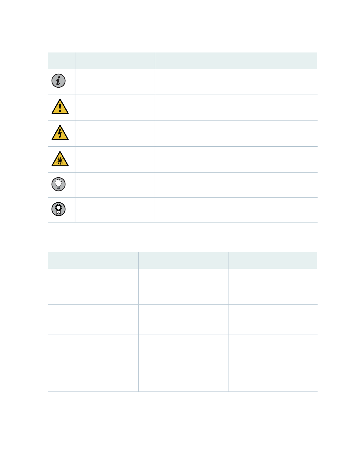
Table 1: Notice Icons
xiii
DescriptionMeaningIcon
Indicates important features or instructions.Informational note
Caution
Indicates a situation that might result in loss of data or hardware
damage.
Alerts you to the risk of personal injury or death.Warning
Alerts you to the risk of personal injury from a laser.Laser warning
Indicates helpful information.Tip
Alerts you to a recommended use or implementation.Best practice
Table 2 on page xiii defines the text and syntax conventions used in this guide.
Table 2: Text and Syntax Conventions
ExamplesDescriptionConvention
Fixed-width text like this
Italic text like this
Represents text that you type.Bold text like this
Represents output that appears on
the terminal screen.
Introduces or emphasizes important
•
new terms.
Identifies guide names.
•
Identifies RFC and Internet draft
•
titles.
To enter configuration mode, type
the configure command:
user@host> configure
user@host> show chassis alarms
No alarms currently active
A policy term is a named structure
•
that defines match conditions and
actions.
Junos OS CLI User Guide
•
RFC 1997, BGP Communities
•
Attribute
Page 14

Table 2: Text and Syntax Conventions (continued)
xiv
ExamplesDescriptionConvention
Italic text like this
Text like this
< > (angle brackets)
| (pipe symbol)
Represents variables (options for
which you substitute a value) in
commands or configuration
statements.
Represents names of configuration
statements, commands, files, and
directories; configuration hierarchy
levels; or labels on routing platform
components.
variables.
Indicates a choice between the
mutually exclusive keywords or
variables on either side of the symbol.
The set of choices is often enclosed
in parentheses for clarity.
Configure the machine’s domain
name:
[edit]
root@# set system domain-name
domain-name
To configure a stub area, include
•
the stub statement at the [edit
protocols ospf area area-id]
hierarchy level.
The console port is labeled
•
CONSOLE.
stub <default-metric metric>;Encloses optional keywords or
broadcast | multicast
(string1 | string2 | string3)
# (pound sign)
[ ] (square brackets)
Indention and braces ( { } )
; (semicolon)
GUI Conventions
Indicates a comment specified on the
same line as the configuration
statement to which it applies.
Encloses a variable for which you can
substitute one or more values.
Identifies a level in the configuration
hierarchy.
Identifies a leaf statement at a
configuration hierarchy level.
rsvp { # Required for dynamic MPLS
only
community name members [
community-ids ]
[edit]
routing-options {
static {
route default {
nexthop address;
retain;
}
}
}
Page 15

Table 2: Text and Syntax Conventions (continued)
xv
ExamplesDescriptionConvention
Bold text like this
> (bold right angle bracket)
Represents graphical user interface
(GUI) items you click or select.
Separates levels in a hierarchy of
menu selections.
In the Logical Interfaces box, select
•
All Interfaces.
To cancel the configuration, click
•
Cancel.
In the configuration editor hierarchy,
select Protocols>Ospf.
Documentation Feedback
We encourage you to provide feedback so that we can improve our documentation. You can use either
of the following methods:
Online feedback system—Click TechLibrary Feedback, on the lower right of any page on the Juniper
•
Networks TechLibrary site, and do one of the following:
Click the thumbs-up icon if the information on the page was helpful to you.
•
Click the thumbs-down icon if the information on the page was not helpful to you or if you have
•
suggestions for improvement, and use the pop-up form to provide feedback.
E-mail—Send your comments to techpubs-comments@juniper.net. Include the document or topic name,
•
URL or page number, and software version (if applicable).
Requesting Technical Support
Technical product support is available through the Juniper Networks Technical Assistance Center (JTAC).
If you are a customer with an active Juniper Care or Partner Support Services support contract, or are
Page 16

covered under warranty, and need post-sales technical support, you can access our tools and resources
online or open a case with JTAC.
JTAC policies—For a complete understanding of our JTAC procedures and policies, review the JTAC User
•
Guide located at https://www.juniper.net/us/en/local/pdf/resource-guides/7100059-en.pdf.
Product warranties—For product warranty information, visit https://www.juniper.net/support/warranty/.
•
JTAC hours of operation—The JTAC centers have resources available 24 hours a day, 7 days a week,
•
365 days a year.
Self-Help Online Tools and Resources
For quick and easy problem resolution, Juniper Networks has designed an online self-service portal called
the Customer Support Center (CSC) that provides you with the following features:
Find CSC offerings: https://www.juniper.net/customers/support/
•
Search for known bugs: https://prsearch.juniper.net/
•
xvi
Find product documentation: https://www.juniper.net/documentation/
•
Find solutions and answer questions using our Knowledge Base: https://kb.juniper.net/
•
Download the latest versions of software and review release notes:
•
https://www.juniper.net/customers/csc/software/
Search technical bulletins for relevant hardware and software notifications:
•
https://kb.juniper.net/InfoCenter/
Join and participate in the Juniper Networks Community Forum:
•
https://www.juniper.net/company/communities/
Create a service request online: https://myjuniper.juniper.net
•
To verify service entitlement by product serial number, use our Serial Number Entitlement (SNE) Tool:
https://entitlementsearch.juniper.net/entitlementsearch/
Creating a Service Request with JTAC
You can create a service request with JTAC on the Web or by telephone.
Visit https://myjuniper.juniper.net.
•
Call 1-888-314-JTAC (1-888-314-5822 toll-free in the USA, Canada, and Mexico).
•
For international or direct-dial options in countries without toll-free numbers, see
https://support.juniper.net/support/requesting-support/.
Page 17

1
CHAPTER
Overview
PTX10001 System Overview | 18
PTX10001 Port Panel | 23
PTX10001 Management Panel | 29
PTX10001 Cooling System | 31
PTX10001 Power System | 34
Expansion Module for the PTX10001 | 44
Page 18

PTX10001 System Overview
IN THIS SECTION
PTX10001 Packet Transport Router Description | 18
PTX10001 Hardware Component Overview | 21
PTX10001 Component Redundancy | 21
PTX10001 Field-Replaceable Units | 22
18
PTX10001 Packet Transport Router Description
IN THIS SECTION
Benefits of the PTX10001 Router | 18
System Overview | 19
Port Panel | 19
Management Panel | 20
Juniper Networks PTX10001 Packet Transport Router is a fixed-configuration MacSec enabled LSR core
router. It features a compact 1U form factor that is easily deployed in space-constrained Internet exchange
locations, remote central offices, and embedded peering points throughout the network.
Benefits of the PTX10001 Router
Scalability—The PTX10001 scales to 3.6 Tbps in a single chassis, supporting up to 144 10-Gigabit Ethernet
•
interfaces, 36 40-Gigabit Ethernet interfaces, and 36 100-Gigabit Ethernet interfaces, giving cloud and
service providers the performance and scalability needed as networks grow.
Performance—The PTX10001’s exceptional packet processing capabilities help alleviate the challenge
•
of scaling the network as traffic levels increase while optimizing IP/MPLS transit functionality around
superior performance. PTX10001 is tailored for LSR core router with support for 128K LSPs.
Page 19

High availability hardware—The PTX10001 is engineered with hardware redundancy for cooling, power
•
supplies, and forwarding. With the PTX10001’s high availability, service providers can maintain an
always-on infrastructure base and to meet stringent SLAs across the core.
Space efficiency—The PTX10001’s ultra-compact 1U form factor efficiency is a critical requirement for
•
peering internet exchange points, peering collocations, central offices, and regional networks. The
PTX10001 is the first 1RU LSR router with MacSec support built in.
System Overview
The PTX10001 is a fixed-configuration router that supports 10-Gbps, 40-Gbps, and 100-Gbps port speeds
in a single 1U stackable platform.
Control operations are performed by the Routing Engine, which runs the Juniper Networks Junos
•
operating system (Junos OS). The Routing Engine handles routing protocols, traffic engineering, policy,
policing, monitoring, and configuration management. Junos OS is installed on the PTX10001 router’s
internal 2 x 50-gigabyte (GB) M.2 SATA solid-state drives (SSDs). The Routing Engine is enhanced by a
1.6-GHz 4 core Intel CPU and 24 GB of SDRAM.
19
Forwarding operations are performed by the Packet Forwarding Engine, which uses Juniper Networks
•
Express-based silicon. The custom ASICs enable the PTX10001 to provide up to 3.6 Tbps of throughput
and 2 Bpps of forwarding capacity.
TIP: For information about features supported on PTX Series routers, see Feature Explorer.
Port Panel
The port panel of the PTX10001 contains 20 network ports, port LEDs, one bay for an optional expansion
module, console and management ports, and system status LEDs. Figure 1 on page 20 shows the PTX10001
port panel.
Page 20
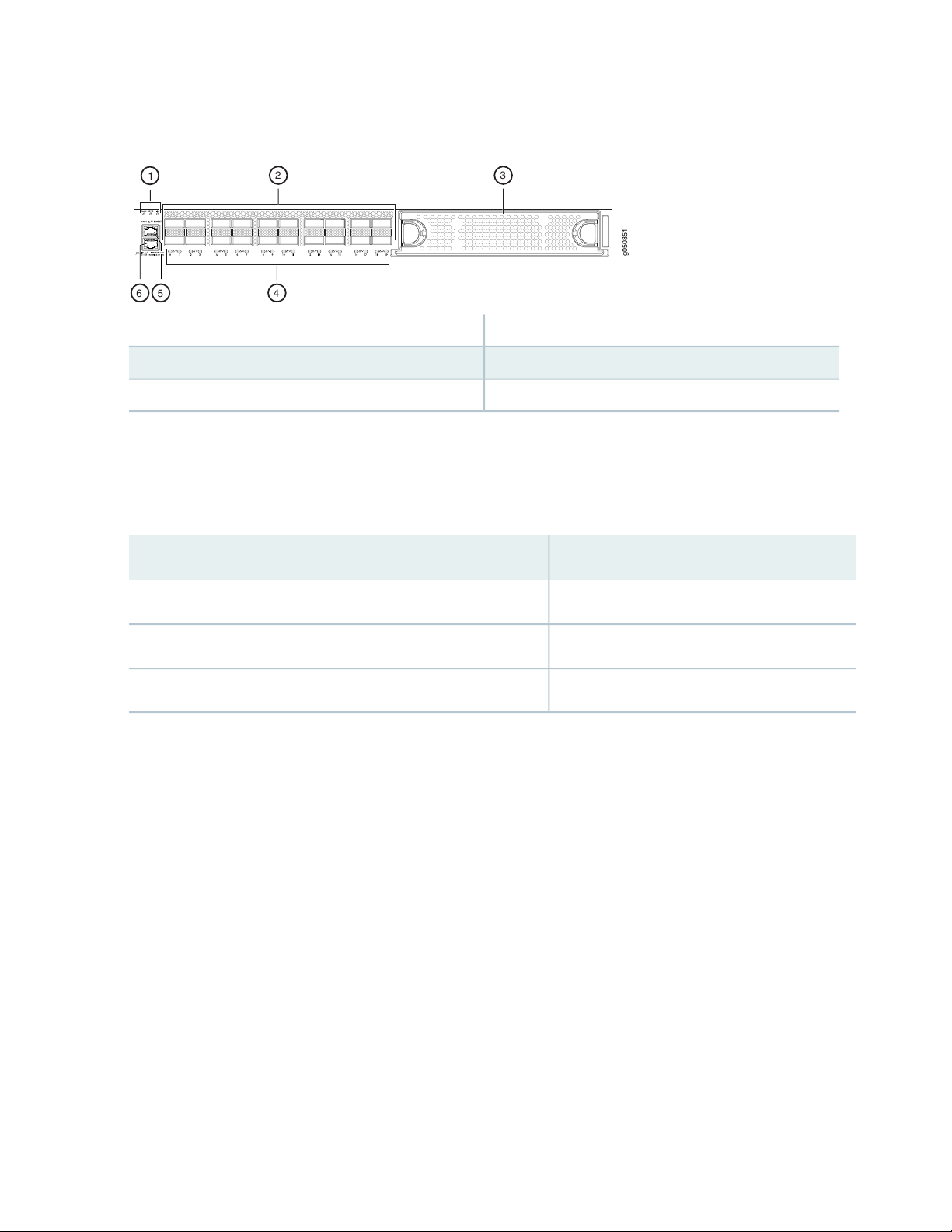
Figure 1: PTX10001 Port Panel and Management Panel
g050851
1
6
2 3
45
4—1— Network port LEDsSystem status LEDs
5—2— Console portNetwork port
6—3— Management portExpansion bay
The 20 network ports on the port panel are QSFP28 ports. Table 3 on page 20 describes the maximum
number of ports for each interface type supported by the PTX10001 with the optional JNP10001-16C-PIC
expansion module installed.
20
Table 3: Maximum Supported Ports at Each Interface Speed
Maximum Supported PortsInterface Type
14410-Gigabit Ethernet
3640-Gigabit Ethernet
36100-Gigabit Ethernet
You manage the PTX10001 by using the Junos OS CLI, which is accessible through the console and
out-of-band management ports on the management panel. In addition, the management panel has system
status LEDs that alert you to minor or major alarms or other issues with the router, external clock
synchronization ports, and a USB port to support software installation and recovery.
Management Panel
The management panel of the PTX10001 is located on the FRU side of the device. It contains management
ports, the fan modules, and power supplies for the PTX10001. Figure 2 on page 21 shows the PTX10001
management panel.
Page 21
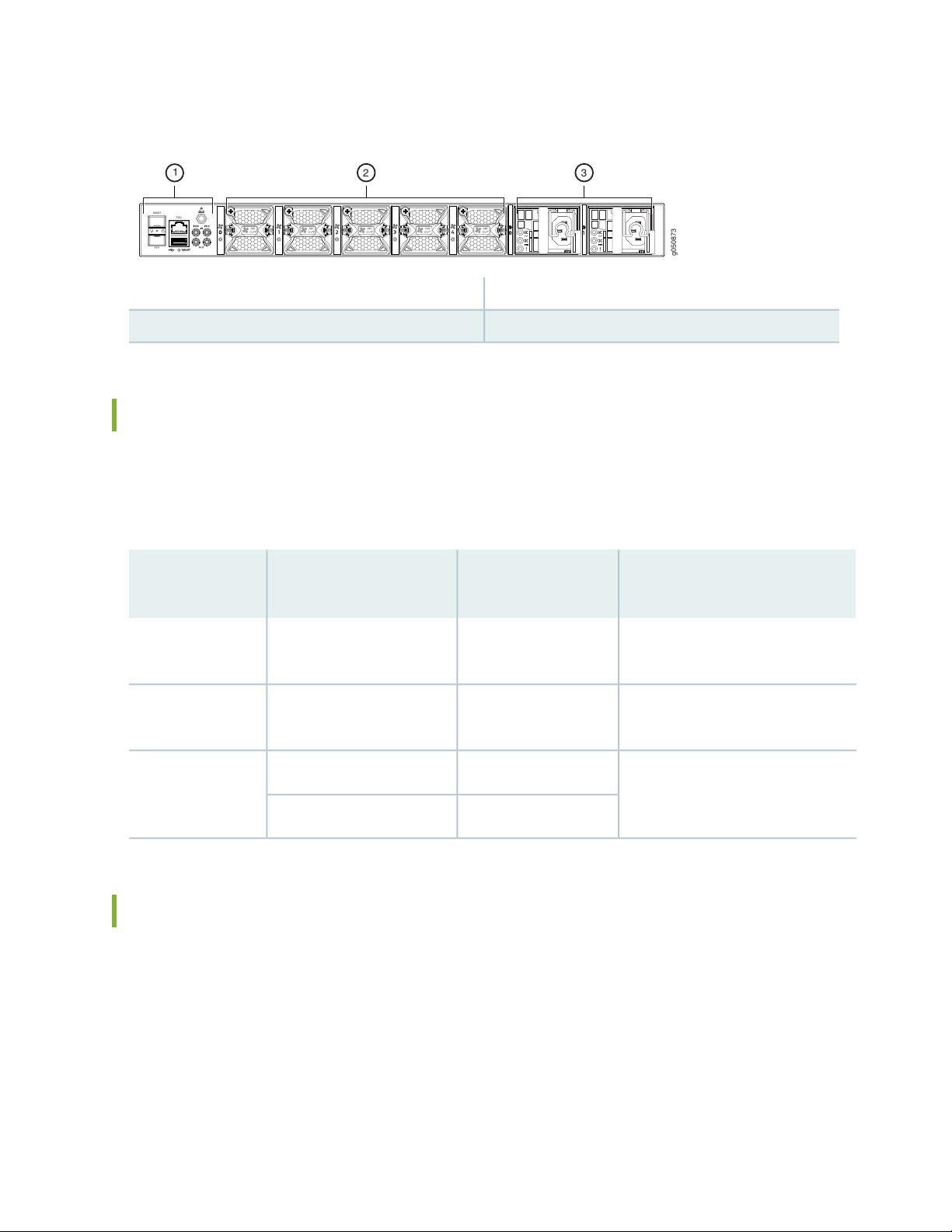
Figure 2: PTX10001 Management Panel
PTP
MGMT
TOD
g050873
2 3
1
3—1— Power supplies (2)Management ports.
2—Fan modules (5)
PTX10001 Hardware Component Overview
The PTX10001 supports the components in Table 4 on page 21 listed in alphabetic order. See “PTX10001
Physical Specifications” on page 53 the dimensions and weight of the PTX10001.
21
Table 4: PTX10001 Hardware Components
Spare Juniper Model
NumberComponent
PTX10001-CHASChassis
JNP-FAN-1RUFan module
JNP10001-20c
[PTX10001]
PTX10001-M20C Fan
Controller
JPSU-850W-AC-AFOJPSU-850W-AC-AFOPower supplies
JPSU-850W-DC-AFOJPSU-850W-DC-AFO
PTX10001 Component Redundancy
The following hardware components provide redundancy on a PTX10001:
DescriptionCLI Output
“PTX10001 Packet Transport Router
Description” on page 18
“PTX10001 Cooling System” on
page 31
“PTX10001 Power System” on
page 34
Power supplies—The PTX10001 has two power supplies. Each power supply provides power to all
•
components in the device. The two power supplies provide full power redundancy to the device. If one
power supply fails or is removed, the second power supply balances the electrical load without
interruption. To provide power redundancy to the system both power supplies must be installed. Connect
power source feed A to one power supply and power source feed B to the second power supply.
Page 22
CAUTION: Do not connect feed A and feed B to the same power supply input
terminal.
Cooling system—The PTX10001 has five fan modules. If a fan module fails and the remaining fan modules
•
are unable to keep the PTX10001 within the desired temperature thresholds, chassis alarms occur and
the PTX10001 can shut down.
PTX10001 Field-Replaceable Units
Field-replaceable units (FRUs) are components that you can replace at your site.
CAUTION: Replace a failed fan module with a new fan module within 30 seconds of
removal to prevent chassis overheating.
22
Table 5 on page 22 lists the FRUs for the PTX10001 and actions to take before removing them.
Table 5: Required Actions Before Removing a FRU from the PTX10001
Required Actions Before RemovalFRU
Power supplies (2)
Remove the power cord or cable for the power supply unit. See “Maintaining
the PTX10001 Power Supplies” on page 103.
See “Maintaining the PTX10001 Fan Modules” on page 100.Fan modules (5)
See “Maintaining a PTX10001 Expansion Module” on page 106.Expansion modules
See “Remove a Transceiver” on page 111.Optical transceivers
NOTE: If you have a Juniper Care service contract, register any addition, change, or upgrade of
hardware components at https://www.juniper.net/customers/support/tools/updateinstallbase/
. Failure to do so can result in significant delays if you need replacement parts. This note does
not apply if you replace existing components with the same type of component.
Page 23

SEE ALSO
RELATED DOCUMENTATION
PTX10001 Port Panel | 23
PTX10001 Management Panel | 29
PTX10001 Cooling System | 31
PTX10001 Power System | 34
PTX10001 Port Panel
23
IN THIS SECTION
PTX10001 Port Panel | 23
PTX10001 Chassis Status LEDs | 25
PTX10001 Management Port LEDs | 27
PTX10001 Network Port LEDs | 28
PTX10001 Port Panel
IN THIS SECTION
Network Ports | 24
Expansion Module Bay | 25
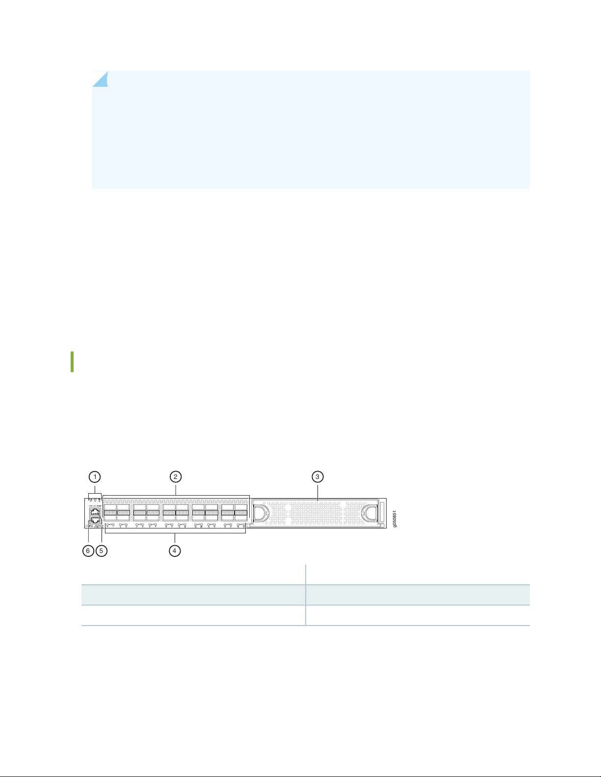
The PTX10001 supports 10-Gbps, 40-Gbps, and 100-Gbps port speeds. Figure 3 on page 24 shows the
PTX10001 port panel.
Page 24
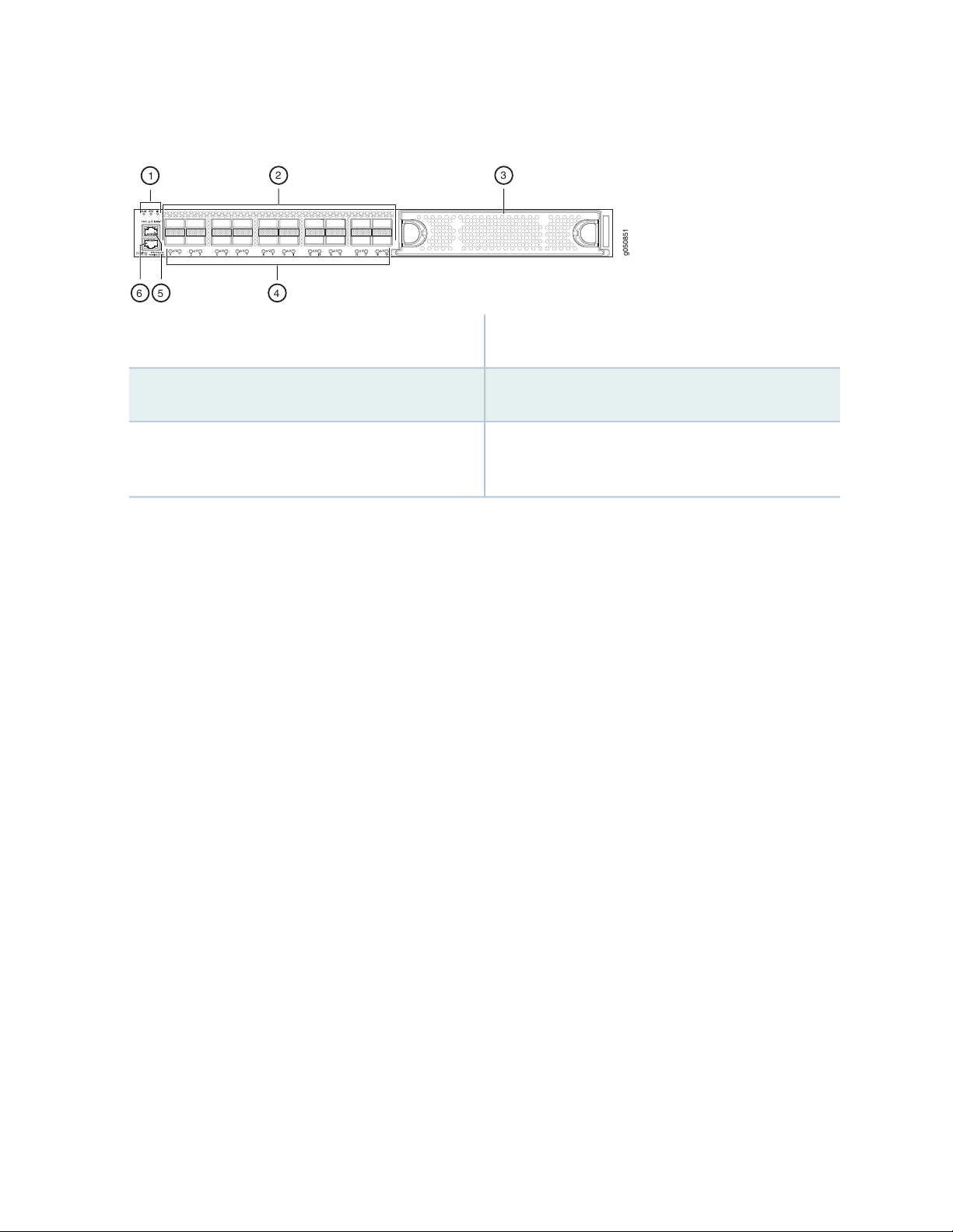
Figure 3: PTX10001 Port Panel
g050851
1
6
2 3
45
identification (ID).
24
4—1— Network port LEDsStatus LEDs—Alarm (ALM), system (SYS),
Network ports
Expansion module bay
5—2— RJ-45 console port (CON) to support RS-232 serial
ports.
6—3— RJ-45 (1000BASE-T) management Ethernet port
(labeled MGMT). In the Junos OS CLI, this port is
identified as em0.
Network Ports
The PTX10001 uses 28-Gbps quad small-form factor pluggable plus (QSFP28) sockets that are configured
as 100 Gigabit Ethernet ports by default.
The PTX10001 network ports (0 to 19) support:
100 Gbps QSFP28 transceivers
•
40 Gbps QSFP+ transceivers
•
100 Gbps active optical cables (AOC)
•
40 Gbps AOC
•
QSFP28 direct attach copper (DAC) cables
•
QSFP+ DAC cables
•
QSFP+ direct attach copper break out (DACBO) cables
•
QSFP28 DACBO cables
•
Page 25
NOTE: Port speeds are configured using the set chassis fpc 0 pic 0 port port-number speed
g050851
1
6
2 3
45
speed command. You configure ports to operate at a particular speed by using the appropriate
speed option. If you configure a port to operate at a certain speed, and you want to return the
port to the default configuration, delete the speed statement from the configuration at the
[chassis fpc 0 pic 0 port port-number] hierarchy level and commit the configuration. The network
port is reset to the default Ethernet interface.
Expansion Module Bay
The PTX10001 has one bay on the port panel for an optional expansion module. The expansion module
is an addition to the PTX10001 chassis and must be ordered separately.
The PTX10001 supports the JNP10001-16C-PIC expansion module. For more information, see “Expansion
Module for the PTX10001” on page 44.
25
PTX10001 Chassis Status LEDs
The PTX10001 has three status LEDs on the port panel of the chassis, next to the network ports (see
Figure 4 on page 25).
Figure 4: PTX10001 Port Panel
4—1— Network port LEDsStatus LEDs
5—2— RJ-45 console portNetwork ports
6—3— RJ-45 management Ethernet portExpansion module bay
Table 6 on page 26 describes the chassis status LEDs on a PTX10001, their colors and states, and the
status they indicate.
Page 26

Table 6: Chassis Status LEDs on a PTX10001 Device
26
DescriptionStateColorName
OffUnlitALM–Alarm
On steadilyRed
On steadilyAmber
The device is halted or there is no
alarm.
A major hardware fault has occurred,
such as a temperature alarm or power
failure, and the device has halted.
Power off the device by setting the AC
power source outlet to the OFF (O)
position, or unplugging the AC power
cords. Correct any voltage or site
temperature issues, and allow the
device to cool down. Power on the
device and monitor the power supply
and fan LEDs to help determine where
the error is occurring.
A minor alarm has occurred, such as a
software error. Power off the device
by setting the AC power source outlet
to the OFF (O) position, or unplugging
the AC power cords. Power on the
device and monitor the status LEDs to
ensure that Junos OS boots properly.
The device is powered off or halted.OffUnlitSYS–System
Junos OS is loaded on the device.On steadilyGreen
OffUnlitID–Identification
BlinkingBlue
The beacon feature is not enabled on
the device. This feature is enabled
using the request chassis beacon
command.
The beacon feature is enabled on the
device. This feature is enabled using
the request chassis beacon command.
Page 27
PTX10001 Management Port LEDs
g050880
21
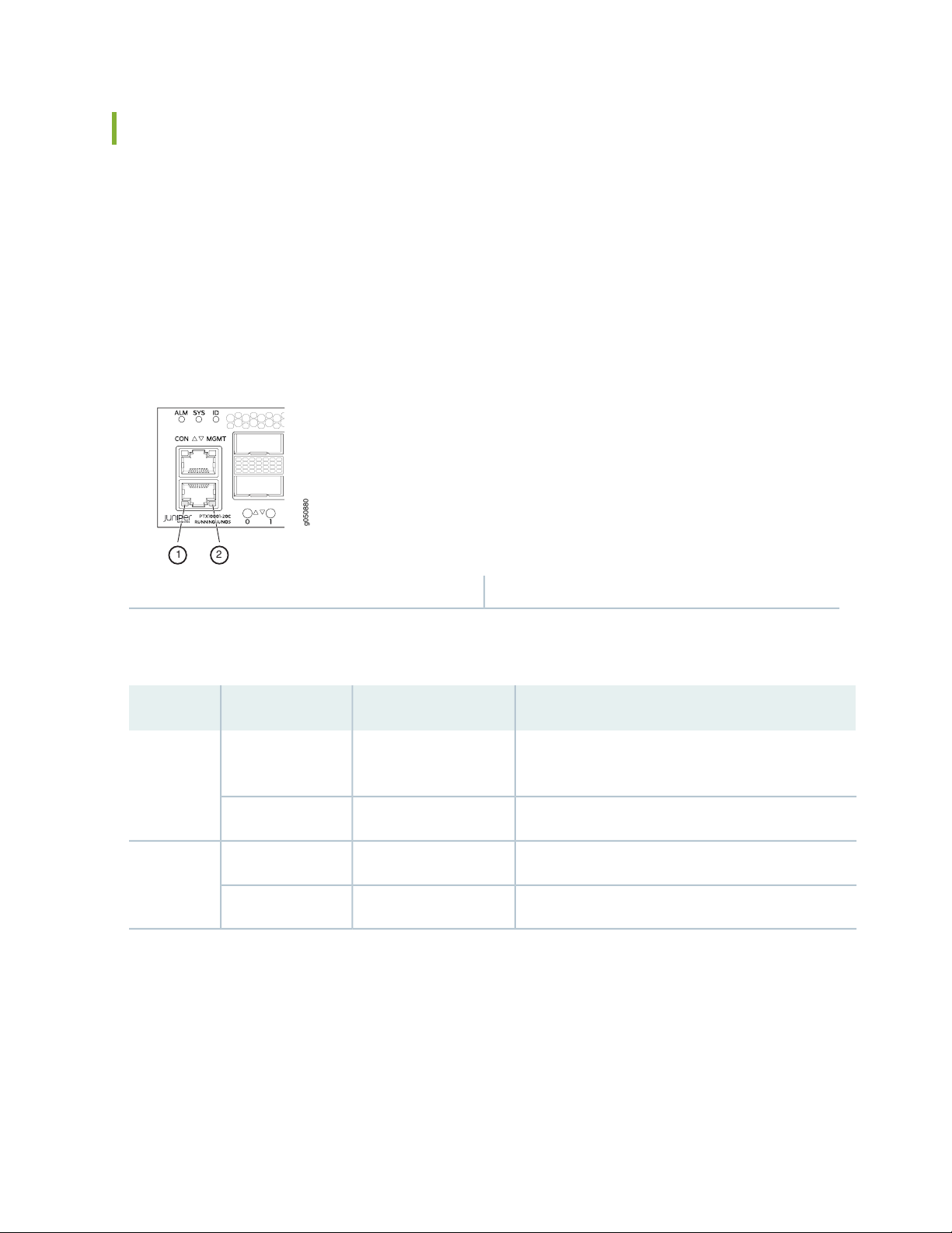
There are two management ports on the PTX10001, Both ports are labeled MGMT. The RJ-45 management
port is for 10/100/1000BASE-T connections and is located on the port panel. The small form-factor
pluggable (SFP) management port is for 10/100/1000BASE-T and 1000BASE-X connections and is located
on the FRU end of the device.
The RJ-45 port has separate LEDs for status and activity. The SFP port has a LED to indicate both link and
activity. Figure 5 on page 27 shows the location of the LEDs.
Figure 5: Management Port LEDs on a PTX10001
27
2—1— Link activity LED (RJ-45)Status LED (RJ-45)
Table 7 on page 27 describes the RJ-45 management port LEDs.
Table 7: PTX10001 RJ-45 Management Port LEDs
DescriptionStateColorLED
OffUnlitLink activity
No link is established, there is a fault, or the link is
down.
A link is established, and there is link activity.Blinking or flickeringAmber
Either the port speed is 10 Mbps or the link is down.OffUnlitStatus
The port speed is 1000 Mbps.On steadilyGreen
Table 8 on page 28 describes the SFP management port LED.
Page 28
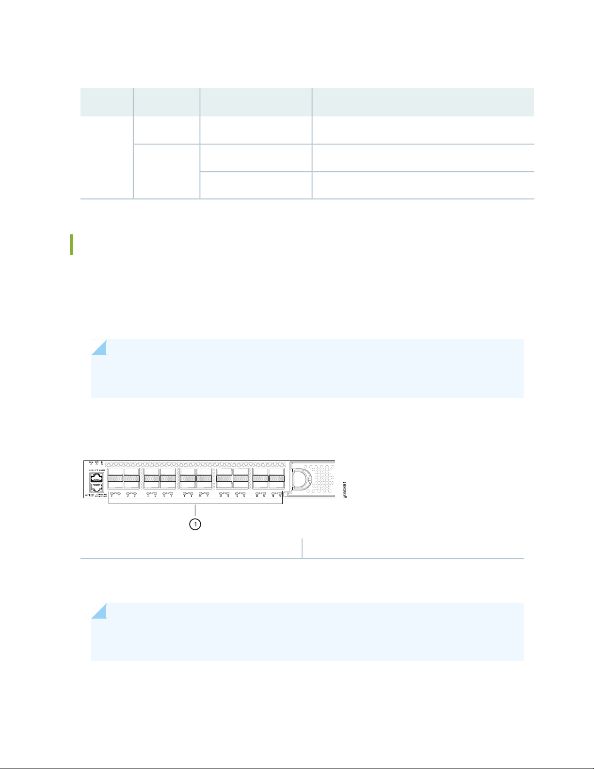
Table 8: PTX10001 SFP Management Port LED
g050891
1
DescriptionStateColorLED
No link is established, there is a fault, or the link is down.OffUnlitLink
activity
A link is established, but there is no link activity.On steadilyGreen
A link is established, and there is link activity.Blinking or flickering
PTX10001 Network Port LEDs
Each PTX10001 network port uses a single bicolored LED to indicate link status and activity. The circular
LEDs are located underneath the ports. The triangular arrow next to the LED points either up or down
indicating whether the LED is associated with the top or bottom port. Figure 6 on page 28 shows the
location of the LEDs.
28
NOTE: All 36 network port LEDs behave the same. Including the 16 network port LEDs located
on the JNP10001-16C-PIC expansion module.
Figure 6: Network Port LEDs on a PTX10001
1—Network port LEDs
The number next to the LED indicates the port number that the LED belongs to and the arrow next to the
LED indicates if it is the top or bottom port.
NOTE: The same bicolored LED also indicates status when the port is configured to operate as
four 10-Gigabit Ethernet interfaces.
Table 9 on page 29 describes the network port LEDs.
Page 29

Table 9: PTX10001 Network Port LEDs
29
DescriptionStateColor
OffUnlit
On steadilyAmber
RELATED DOCUMENTATION
PTX10001 System Overview | 18
PTX10001 Management Panel | 29
show chassis alarms
request chassis beacon
The port is administratively disabled, there is no power, the link is down,
or a transceiver is not present.
A link is established.On steadilyGreen
The beacon function was enabled on the port.Blinking
When the port is configured to operate as four 10-Gigabit Ethernet
interfaces, indicates that one or more interfaces (but not all four) are up.
There are one or more errors on the connections.Blinking
PTX10001 Management Panel
IN THIS SECTION
PTX10001 Management Panel | 29
PTX10001 Management Panel
The PTX10001 management panel is found on the Field Replaceable Unit (FRU) end of the device.
Page 30
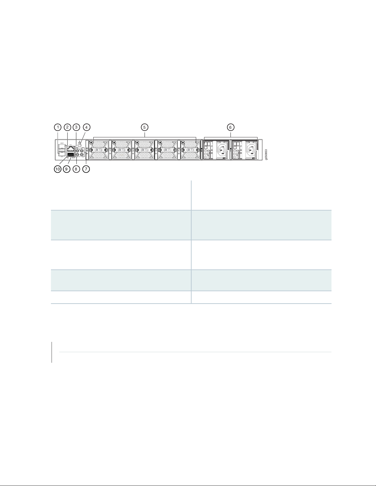
You manage the PTX10001 by using the Junos OS CLI, which is accessible through the console and
PTP
MGMT
TOD
g050853
54 6
910
8
3
2
1
7
out-of-band management ports on the management panel. In addition, the management panel has system
status LEDs that alert you to minor or major alarms or other issues with the router, external clock
synchronization ports, and a USB port to support software installation and recovery. See
Figure 7 on page 30for management panel details.
Figure 7: PTX10001 Management Panel
6—1— Power suppliesSFP PTP Ethernet (1000BASE-T) port (labeled PTP).
The PTP port is not currently supported. It is reserved
for future use.
30
SFP management Ethernet port (labeled MGMT). In
the Junos OS CLI, this port is identified as em2.
RS-232 Time-of-day port (labeled TOD). The TOD
port is not currently supported. It is reserved for
future use.
Electrostatic discharge (ESD) terminal
RELATED DOCUMENTATION
PTX10001 System Overview | 18
PTX10001 Port Panel | 23
7—2— Pulses-per-second SMB connector (labeled PPS) input
and output. The PPS port is not currently supported.
It is reserved for future use.
8—3— 10 MHz SubMiniature B (SMB) connector (labeled
10M) input and output. The 10M port is not currently
supported. It is reserved for future use.
9—4— Reset button. Press and hold for 5 seconds to reset
the hardware.
10—5— USB port.Fan modules
Page 31

PTX10001 Cooling System
IN THIS SECTION
PTX10001 Cooling System Description | 31
PTX10001 Fan Module LEDs | 33
PTX10001 Cooling System Description
IN THIS SECTION
31
Fan Modules | 31
Airflow Through the Chassis | 33
Fan Modules
The cooling system in a PTX10001 device consists of fan modules and a single fan in each power supply.
There are five fan modules in the PTX10001. The airflow direction on the PTX10001 is airflow out, air
comes into the device through the vents in the port panel.
The fan modules in the PTX10001 are hot-insertable and hot-removable field-replaceable units (FRUs).
These fan modules are designed for the airflow out direction. The fan modules are installed in the fan
module slots on the management panel of the device next to the power supplies. The PTX10001 has 5
fan modules numbered 0 through 4 from left to right. Each fan module slot has a fan icon next to it.
Figure 8 on page 32 shows the location of the fan modules on the device. Figure 9 on page 32 shows an
example of the fan module.
Page 32

Figure 8: PTX10001 FRU Panel
PTP
MGMT
TOD
g050873
2 3
1
g050868
3—1— Power supplies (2)Management panel
2—Fan modules (5)
Figure 9 on page 32 shows the fan module for the PTX10001.
Figure 9: PTX10001 Fan Module
32
You remove and replace a fan module from the FRU end of the chassis. During replacement, the device
continues to operate if a fan module is removed. If all fan modules are removed, the device will operate
for 30 seconds before the device shuts down.
NOTE: All fan modules must be installed for optimal operation of the device.
Table 10 on page 32 lists the fan module product SKU.
Table 10: PTX10001 Fan Modules
Label on the Fan
ModuleFan Module
AIR OUTJNP-FAN-1RU
Direction of Airflow in the Fan
Module
Port-to-FRU, that is, air comes in
through vents on the end with ports;
air exhausts out the end with the fans
(also known as front-to-back airflow).
Power Supplies
You must install only power
supplies that have AIR OUT
labels in devices in which
the fan modules have AIR
OUT labels.
Page 33

Airflow Through the Chassis
g050875
Ports FRUs
In the PTX10001 cooling system, cool air enters through the vents in the port panel and hot air exhausts
through the FRU panel. This type of airflow is known as airflow out or port-to-FRU airflow. When the chassis
is installed, it must be positioned so that the FRUs are next to the hot aisle. Figure 10 on page 33 shows
the airflow through the chassis.
Figure 10: Airflow Through the PTX10001 Chassis (Port-to-FRU)
33
NOTE: Under normal operating conditions, the fan modules operate at a moderate speed.
Temperature sensors in the chassis monitor the temperature within the chassis. The system
raises an alarm if a fan module fails or if the ambient temperature inside the chassis rises above
the acceptable range. If the temperature inside the chassis rises above the threshold temperature,
the system shuts down automatically.
PTX10001 Fan Module LEDs
You can check the status of fan modules through the show system alarms command or by looking at the
LEDs next to each fan module.
Figure 11 on page 34 shows the location of the LED next to the fan module.
Page 34

Figure 11: Fan Module LEDs on a PTX10001
PTP
MGMT
TOD
g050890
1
1—Fan LED
Use Table 11 on page 34 describes the function of the fan module LED.
Table 11: PTX10001 Fan Module LED
DescriptionLED StateLED Color
34
On steadilyGreen
The fan module is operating normally. The system has verified that the module
is engaged, that the airflow is in the correct direction, and that the fan is
operating correctly.
BlinkingAmber
An error has been detected in the fan module. Replace the fan module as soon
as possible. Either the fan has failed or it is seated incorrectly. To maintain
proper airflow through the chassis, leave the fan module installed in the chassis
until you are ready to replace it.
RELATED DOCUMENTATION
PTX10001 System Overview | 18
PTX10001 Power System | 34
PTX10001 Power System
IN THIS SECTION
PTX10001 AC Power Supply Description | 35
PTX10001 AC Power Supply LEDs | 36
PTX10001 DC Power Supply Description | 37
PTX10001 DC Power Supply LEDs | 39
PTX10001 AC Power Specifications | 40
Page 35

PTX10001 AC Power Cord Specifications | 40
PTP
MGMT
TOD
g050873
2 3
1
PTX10001 DC Power Specifications | 42
PTX10001 DC Power Cable Specifications | 42
PTX10001 AC Power Supply Description
The two power supplies in a PTX10001 are hot-removable and hot-insertable field-replaceable units
(FRUs). The power supplies are installed in the device at the factory. You can install replacement power
supplies from the management panel without powering off the device or disrupting the devices functions.
The AC power supply is 850 W. Figure 12 on page 35 shows the location of the power supplies on the
FRU end of the device. Figure 13 on page 36 shows an example of the AC power supply. The PTX10001
has two power supplies.
35
CAUTION: Do not mix AC and DC power supplies in the same chassis.
Figure 12: PTX10001 FRU Panel
2—Fan modules (5)
3—1— Power supplies (2)Management panel
Page 36

Figure 13: AC Power Supply in a PTX10001
g050255
1 2
3
4
g050857
1
2
3
3—1— AC application inletHandle
4—2— Latch leverCord retainer
When the PTX10001 has both power supplies installed and connected to power, the device has full power
redundancy. If a power supply fails or is removed, another power supply balances the electrical load without
interruption.
36
CAUTION: To avoid electrical injury, carefully follow instructions in “Connecting the
PTX10001 to Power” on page 80, “Maintaining the PTX10001 Power Supplies” on
page 103.
PTX10001 AC Power Supply LEDs
Figure 14 on page 36 shows the location of the LED on the power supply.
Figure 14: AC Power Supply LED on a PTX10001
Table 12 on page 37describes the LEDs on the AC power supplies.
Page 37

Table 12: PTX10001 AC Power Supply LEDs
37
DescriptionStateColorLED
OffUnlitAC
OffUnlitDC
On steadilyAmber! (Fault)
The power supply is disconnected from power, or power is not
coming into the power supply.
Power is coming into the power correctly.On steadilyGreen
The power supply is disconnected from power, or the power supply
is not sending out power correctly.
The power supply is sending out power correctly.On steadilyGreen
An error has been detected in the power supply. Replace the power
supply as soon as possible. To maintain proper airflow through the
chassis, leave the power supply installed in the chassis until you
are ready to replace it.
NOTE: If the AC LED and the DC LED are unlit, either the AC power cord is not installed properly
or the power supply fuse has failed. If the AC LED is lit and the DC LED is unlit, the AC power
supply is installed properly, but the power supply has an internal failure.
PTX10001 DC Power Supply Description
The power supplies in PTX100001 devices (see Figure 15 on page 38)are hot-removable and hot-insertable
field-replaceable units (FRUs) that you can install in a PTX10001 device without powering off the device
or disrupting the routing functions.
The DC power supply is 850 W with dual feeds for power resiliency.
Page 38

Figure 15: PTX10001 DC Power Supply
g050862
2
3
4
5678
1
3—1— Latch leverTerminal block
4—2— HandleESD grounding point
NOTE: The DC power supply has four terminals labeled V-, V-, V+, and V+ (see
Figure 16 on page 38 for connecting DC power source cables labeled positive (+) and negative
(–).
38
Figure 16: PTX10001 DC Power Supply Faceplate
5—1— — ESD grounding point— Shunt negative input terminals (-48V)
6—2— — Fault LED— Shunt positive input terminals (+RTN)
7—3— — Output LED— Terminal block
8—4— — Input LED— Latch lever
Page 39

CAUTION: To avoid electrical injury, carefully follow instructions in “Connecting the
PTX10001 to Power” on page 80, “Maintaining the PTX10001 Power Supplies” on
page 103.
SEE ALSO
PTX10001 DC Power Supply LEDs
Figure 16 on page 38shows the location of the LED on the DC power supply.
39
CAUTION: The V+ terminals are shunted internally together, as are the V- terminals.
The same polarity terminal can be wired together from the same source to provide an
additional current path in a higher power chassis. Do not connect the terminals to
different sources.
Table 13 on page 39describes the LEDs on the DC power supplies.
Table 13: PTX10001 DC Power Supply LEDs
DescriptionStateColorName
OffUnlitIN
OffUnlitOUT
The power supply is disconnected from power or power is not
coming into the power supply.
Power is coming into the power supply.On steadilyGreen
The power supply is disconnected from power or the power supply
is not sending out power correctly.
Power is sending out power correctly.On steadilyGreen
On steadilyAmber! (Fault)
An error has been detected in the power supply. Replace the power
supply as soon as possible. To maintain proper airflow through the
chassis, leave the power supply installed in the chassis until you
are ready to replace it.
Page 40

PTX10001 AC Power Specifications
Table 14 on page 40 describes the AC power specifications for PTX10001 AC power supplies.
Table 14: AC Power Specifications for a PTX10001 Device
SpecificationItem
40
AC input voltage
AC input current rating
Operating range:
100 / 240 VAC
•
50–60 HzAC input line frequency
4.5 A at 100–120 VAC
•
2.0 A at 200–240 VAC
•
632 WTypical power consumption
663 WMaximum power consumption
PTX10001 AC Power Cord Specifications
Detachable AC power cords are shipped with the chassis, if you include them as part of your order. The
coupler is type C13 as described by International Electrotechnical Commission (IEC) standard 60320. The
plug end of the power cord fits into the power source outlet that is standard for your geographical location.
NOTE: In North America, AC power cords must not exceed 14.75 feet (approximately 4.5 meters)
in length, to comply with National Electrical Code (NEC) Sections 400-8 (NFPA 75, 5-2.2) and
210-52, and Canadian Electrical Code (CEC) Section 4-010(3).
Table 15 on page 41 lists AC power cord specifications provided for each country or region.
Page 41

Table 15: AC Power Cord Specifications
g021274
41
Australia
China
Europe (except
Italy, Switzerland,
and United
Kingdom)
Italy
Japan
North America
Electrical
SpecificationsCountry/Region
250 VAC, 10 A,
50 Hz
250 VAC, 10 A,
50 Hz
50 Hz
50 Hz
50 Hz or 60 Hz
250 VAC, 13 A,
60 Hz
250 VAC, 13 A,
60 Hz
Plug
Standards
3109-1996
1002-1996
No. 49-92
NEMA L6-15
NEMA 6-15
Shipped Juniper
Model Number
CG_CBL-C13-06-USCAN/CSA
Spare Juniper Model
Number
CBL-EX-PWR-C13-AUCG_CBL-C13-06-AUAS/NZ
CBL-EX-PWR-C13-CHCG_CBL-C13-06-CHGB
CBL-EX-PWR-C13-EUCG_CBL-C13-06-EUCEE (7) VII250 VAC, 10 A,
CBL-EX-PWR-C13-ITCG_CBL-C13-06-ITCEI 23-16/VII250 VAC, 10 A,
CBL-EX-PWR-C13-JPCG_CBL-C13-06-JPJIS C8303125 VAC, 12 A,
CBL-EX-PWR-C13-US
CBL-PW-C13-250-US
CBL-PWR-C13-250-US
Graphic
South Korea
Switzerland
United Kingdom
250 VAC, 10 A,
60 Hz
250 VAC, 13 A,
60 Hz
250 VAC, 10 A,
50 Hz
50 Hz
CBL-EX-PWR-C13-KRCG_CBL-C13-06-KRKSC 8305;
K60884-1
CBL-EX-PWR-C13-SZCG_CBL-C13-06-SZSEV 1011
SEV 1991;
EN 60320
C13
CBL-EX-PWR-C13-UKCG_CBL-C13-06-UKBS 1363/A250 VAC, 10 A,
Page 42

PTX10001 DC Power Specifications
Table 16 on page 42 describes the DC power specifications for PTX10001 DC power supplies.
Table 16: DC Power Specifications for a PTX10001
SpecificationsItem
42
DC input voltage
Rated operating voltage: –48 VDC to -60 VDC
•
Operating voltage range: -40 VDC through –72 VDC
•
Rated operating voltage: VDC -48 VDC to -60 VDC
•
Operating voltage range: –40 VDC through -72 VDC
•
10 A maximumDC input current rating
646 WTypical power consumption
676 WMaximum power consumption
PTX10001 DC Power Cable Specifications
PTX10001 DC power supplies require a D-Sub 3W3- type connector. The three pins on the connector
provide –48 VDC input (–), return (+), and ground connections to the power supply.
NOTE: The optional right-angle DC power cables, CBL-JNP-PWR-DSUB2 and
CBL-JNP-PWR-DSUB3, do not include a ground connection wire.
Regardless which DC power cable you use, you must connect the PTX10001 to earth ground
before you connect it to to power, using the procedure described in “Connecting the PTX10001
to Ground” on page 81.
DC power cables, each approximately 13.1 ft (4 m) long, are supplied with the PTX10001. The provided
cables include the three-pin connector on one end and insulated wires at the opposite end, for connection
to the site’s DC power distribution system.
Table 17 on page 43 lists the specifications for the PTX10001 DC power cables.
Page 43

Table 17: PTX10001 DC Power Cable Specifications
(straight cable)
(right-angle cable)
43
Wire SizeInsulation ColorWire FunctionJuniper Model Number
8 AWG (8.4 mm²), 90° CBlue–48 VDC input (–)CBL-JNP-PWR-DSUB
8 AWG (8.4 mm²), 90° CBlackReturn (+)
8 AWG (8.4 mm²), 90° CGreen and yellowGround
8 AWG (8.4 mm²), 90° CBlue–48 VDC input (–)CBL-JNP-PWR-DSUB2
8 AWG (8.4 mm²), 90° CBlackReturn (+)
8 AWG (8.4 mm²), 90° CGray–48 VDC input (–)CBL-JNP-PWR-DSUB3
(FT4 vertical-flame rated,
right-angle cable)
WARNING: For field-wiring connections, use copper conductors only.
WARNING: Power cables must not block access to PTX10001 components or drape
where people could trip over them.
CAUTION: You must ensure that power connections maintain the proper polarity.
The power source cables might be labeled (+) and (–) to indicate their polarity. There
is no standard color coding for DC power cables. The color coding used by the external
DC power source at your site might be different from the color coding for the leads
on the DC power cable provided with the chassis.
8 AWG (8.4 mm²), 90° CGrayReturn (+)
SEE ALSO
RELATED DOCUMENTATION
Page 44

PTX10001 System Overview | 18
Maintaining the PTX10001 Power Supplies | 103
Expansion Module for the PTX10001
IN THIS SECTION
JNP10001-16C-PIC | 44
The PTX10001 has one bay on the port panel for an optional expansion module. For instructions on
replacing an expansion module, see “Maintaining a PTX10001 Expansion Module” on page 106.
44
The PTX10001 supports the JNP10001-16C-PIC expansion module.
JNP10001-16C-PIC
The JNP10001-16C-PIC expansion module provides 16 additional QSFP28 ports. The QSFP28 ports
support 10-Gbps, 40-Gbps, and 100-Gbps port speeds.
Figure 17 on page 45 shows the JNP10001-16C-PIC ports and LEDs.
Page 45

Figure 17: JNP10001-16C-PIC Faceplate and LEDs
g100323
21
4
3
5
3—Expansion module status LEDs (OK/Fail)
The JNP10001-16C-PIC network ports support:
45
4—1— Offline button (OFFLINE)Lane LEDs (L0 to L3)
5—2— QSFP28 network portsNetwork port LEDs (0 to 15)
100 Gbps QSFP28 transceivers
•
40 Gbps QSFP+ transceivers
•
100 Gbps active optical cables (AOC)
•
40 Gbps AOC
•
QSFP28 direct attach copper (DAC) cables
•
QSFP+ DAC cables
•
QSFP+ direct attach copper break out (DACBO) cables
•
QSFP28 DACBO cables
•
Description
Hardware features
Weight: 3.2 lb (1.45 kg)
•
Power requirement: 200 W
•
Name in the CLI: 16xQSFP28 Macsec TIC
•
Sixteen 100-Gigabit Ethernet ports that support quad small form-factor pluggable
•
(QSFP28) transceivers
The ports are numbered 0 through 15.
•
Each port can be configured as a 100-Gigabit Ethernet port, 40-Gigabit Ethernet port,
•
or as four 10-Gigabit Ethernet ports (by using a breakout cable).
Software features
Supports rate selectability at the port level.
•
By default, the ports are configured as 100-Gigabit Ethernet ports.
•
Supports remote port identification.
•
Supports Media Access Control Security (MACsec)
•
Page 46

46
Cables and
connectors
LEDs
TIP: You can use the Hardware Compatibility Tool to find information about the pluggable
transceivers supported on your Juniper Networks device.
OK/FAIL LED, one bicolor:
•
OFF—The expansion module is offline.
•
Green—The expansion module is online.
•
Red—The expansion module is in a power failure state.
•
Port LED:
•
Off—Link is not plugged in.
•
Green—Link is up.
•
Amber—Link is down due to loss of signal or it is configured down.
•
Red—Link is down.
•
Lane LEDs:
•
Off—No demand for diagnosis or the lane number does not apply to the selected port.
•
Green—Lane is up.
•
Amber—Link is down due to loss of signal or it is configured down.
•
Red—Link is down.
•
RELATED DOCUMENTATION
PTX10001 System Overview | 18
PTX10001 Management Panel | 29
show chassis alarms
request chassis beacon
Page 47

2
CHAPTER
Site Planning, Preparation, and
Specifications
PTX10001 Site Preparation Checklist | 48
PTX10001 Site Guidelines and Requirements | 49
PTX10001 Network Cable and Transceiver Planning | 57
PTX10001 Management Cable Specifications and Pinouts | 68
Page 48

PTX10001 Site Preparation Checklist
The checklist in Table 18 on page 48 summarizes the tasks you need to perform when preparing a site for
a PTX10001 installation.
Table 18: Site Preparation Checklist
Performed
byFor More InformationItem or Task
Environment
48
Date
Verify that environmental factors such as
temperature and humidity do not exceed router
tolerances.
Power
Measure the distance between external power
sources and the router installation site.
Calculate the power consumption and requirements.
Rack or Cabinet
Verify that your rack or cabinet meets the minimum
requirements for the installation of the router.
Plan rack or cabinet location, including required
space clearances.
“PTX10001 Environmental
Requirements and Specifications” on
page 50
PTX10001 AC Power Specifications
•
on page 40
PTX10001 AC Power Cord
•
Specifications on page 40
“PTX10001 Rack Requirements” on
page 54
“PTX10001 Clearance Requirements for
Airflow and Hardware Maintenance” on
page 52
Secure the rack or cabinet to the floor and building
structure.
Cables
Page 49

Table 18: Site Preparation Checklist (continued)
Performed
byFor More InformationItem or Task
49
Date
Acquire cables and connectors:
Determine the number of cables needed based
•
on your planned configuration.
Review the maximum distance allowed for each
•
cable. Choose the length of cable based on the
distance between the hardware components
being connected.
Plan the cable routing and management.
RELATED DOCUMENTATION
PTX10001 Installation Safety Guidelines | 74
Installation Instructions Warning | 153
Chassis and Component Lifting Guidelines | 153
Restricted Access Warning | 155
Ramp Warning | 157
Determining Transceiver Support for
•
the PTX10001 on page 57
Cable and Connector Specifications
•
for MX and PTX Series Devices on
page 58
Rack-Mounting and Cabinet-Mounting Warnings | 158
Grounded Equipment Warning | 164
PTX10001 Site Guidelines and Requirements
IN THIS SECTION
PTX10001 Environmental Requirements and Specifications | 50
General Site Guidelines | 51
PTX10001 Chassis Grounding Cable and Lug Specifications | 51
PTX10001 Clearance Requirements for Airflow and Hardware Maintenance | 52
PTX10001 Physical Specifications | 53
Site Electrical Wiring Guidelines | 53
Page 50

PTX10001 Rack Requirements | 54
PTX10001 Cabinet Requirements | 56
PTX10001 Environmental Requirements and Specifications
The PTX10001 must be installed in a rack or cabinet. It must be housed in a dry, clean, well-ventilated,
and temperature-controlled environment.
Follow these environmental guidelines:
The site must be as dust-free as possible, because dust can clog air intake vents and filters, reducing the
•
efficiency of the PTX10001 cooling system.
50
Maintain ambient airflow for normal PTX10001 operation. If the airflow is blocked or restricted, or if
•
the intake air is too warm, the chassis might overheat, leading to the PTX10001 temperature monitor
shutting down the router to protect the hardware components.
Table 19 on page 50 provides the required environmental conditions for normal PTX10001 operation.
Table 19: PTX10001 Environmental Tolerances
ToleranceDescription
No performance degradation up to 6,562 feet (2000 meters).Altitude
Relative humidity
Temperature
Normal operation ensured in relative humidity range of 5% through 90%, noncondensing.
•
Short-term operation ensured in relative humidity range of 5% through 93%,
•
noncondensing.
NOTE: As defined in NEBS GR-63-CORE, Issue 3, short-term events can be up to 96
hours in duration but not more than 15 days per year.
Normal operation ensured in temperature range of 32° F through 104° F (0° C through
•
40° C).
Nonoperating storage temperature in shipping container: –40° F through 158° F (–40° C
•
through 70° C).
Seismic
Designed to comply with Zone 4 earthquake requirements per NEBS GR-63-CORE, Issue
3.
Page 51

NOTE: Install the PTX10001 only in restricted areas, such as dedicated equipment rooms and
equipment closets, in accordance with Articles 110-16, 110-17, and 110-18 of the National
Electrical Code, ANSI/NFPA 70.
General Site Guidelines
Efficient device operation requires proper site planning and maintenance and proper layout of the equipment,
rack or cabinet (if used), and wiring closet.
To plan and create an acceptable operating environment for your device and prevent environmentally
caused equipment failures:
Keep the area around the chassis free from dust and conductive material, such as metal flakes.
•
51
Follow prescribed airflow guidelines to ensure that the cooling system functions properly and that
•
exhaust from other equipment does not blow into the intake vents of the device.
Follow the prescribed electrostatic discharge (ESD) prevention procedures to prevent damaging the
•
equipment. Static discharge can cause components to fail completely or intermittently over time.
Install the device in a secure area, so that only authorized personnel can access the device.
•
PTX10001 Chassis Grounding Cable and Lug Specifications
For installations that require a separate grounding conductor to the chassis, the PTX10001 must be
adequately grounded before power is connected to ensure proper operation and to meet safety and
electromagnetic interference (EMI) requirements. To ground a PTX10001, connect a grounding cable to
earth ground and then attach it to the chassis grounding points.
WARNING: The device is a pluggable type A equipment installed in a restricted-access
location. It has a separate protective earthing terminal provided on the chassis in
addition to the grounding pin of the power supply cord. This separate protective
earthing terminal must be permanently connected to earth ground for installations
that require a separate grounding conductor to the chassis.
Page 52

WARNING: To comply with GR-1089 requirements, all intrabuilding copper cabling
g050876
19 in.
(4 8 .26 cm)
Clea ran c e requi red
for main t enan c e
24 in. ( 6 1 cm)
25.92 in. ( 65.83 cm)
FRUsPorts
17.36 in.
(44 .09 cm)
Clea ran c e requi red
for main t enan c e
24 in. ( 6 1 cm)
24 .40 in. ( 61.98 cm)
used for SFP+, QSFP+, and QSFP28 ports must be shielded and grounded at both
ends.
CAUTION: Before device installation begins, a licensed electrician must attach a cable
lug to the grounding cables that you supply. See “Connecting the PTX10001 to Ground”
on page 81. A cable with an incorrectly attached lug can damage the PTX10001.
Before connecting the PTX10001 to earth ground, review the following information:
The grounding lug required is a Panduit LCD10-10A-L or equivalent (not provided). The grounding lug
•
accommodates 14–10 AWG (2–5.3 mm²) stranded wire.
The grounding cable that you provide for a PTX10001 must be the same size or heavier than the input
•
wire of each power supply. Minimum recommendations are 14 AWG (2 mm²) stranded wire, 60° C wire,
or as permitted by local code.
52
PTX10001 Clearance Requirements for Airflow and Hardware Maintenance
When planning the site for a PTX10001 installation, you must allow sufficient clearance around the installed
chassis (see Figure 18 on page 52).
Figure 18: Clearance Requirements for Airflow and Hardware Maintenance for a PTX10001
Follow these guidelines:
Page 53

For the cooling system to function properly, the airflow around the chassis must be unrestricted. See
•
“PTX10001 Cooling System” on page 31 for more information about the airflow through the chassis.
If you are mounting a PTX10001 in a rack with other equipment, ensure that the exhaust from other
•
equipment does not blow into the intake vents of the chassis.
You must leave at least 24 in. (61 cm) both in front of and behind the PTX10001 for service personnel
•
to remove and install hardware components, you must leave adequate space at the front and back of
the PTX10001. NEBS GR-63 recommends that you allow at least 30 in. (76.2 cm) in front of the rack or
cabinet and 24 in. (61 cm) behind the rack.
PTX10001 Physical Specifications
Table 20 on page 53 lists the physical specifications for the PTX10001 chassis.
Table 20: Physical Specifications for the PTX10001
53
DepthWidthHeightWeightProduct SKU
PTX10001-20C
fans installed: 26.8 lbs (12.2 kg)
1.72 in. (4.3 cm)With all power supplies and
17.36 in.
(44.09 cm)
25.92 in.
(65.83 cm)
Site Electrical Wiring Guidelines
Table 21 on page 54 describes the factors you must consider while planning the electrical wiring at your
site.
WARNING: You must provide a properly grounded and shielded environment and use
electrical surge-suppression devices.
Avertissement Vous devez établir un environnement protégé et convenablement mis
à la terre et utiliser des dispositifs de parasurtension.
Page 54

Table 21: Site Electrical Wiring Guidelines
Site Wiring
Factor
Guidelines
54
Signaling
limitations
Radio
frequency
interference
Electromagnetic
compatibility
If your site experiences any of the following problems, consult experts in electrical surge suppression
and shielding:
Improperly installed wires cause radio frequency interference (RFI).
•
Damage from lightning strikes occurs when wires exceed recommended distances or pass between
•
buildings.
Electromagnetic pulses (EMPs) caused by lightning damage unshielded conductors and electronic
•
devices.
To reduce or eliminate RFI from your site wiring, do the following:
Use a twisted-pair cable with a good distribution of grounding conductors.
•
If you must exceed the recommended distances, use a high-quality twisted-pair cable with one
•
ground conductor for each data signal when applicable.
If your site is susceptible to problems with electromagnetic compatibility (EMC), particularly from
lightning or radio transmitters, seek expert advice.
Some of the problems caused by strong sources of electromagnetic interference (EMI) are:
Destruction of the signal drivers and receivers in the device
•
Electrical hazards as a result of power surges conducted over the lines into the equipment
•
PTX10001 Rack Requirements
The PTX10001 chassis is designed to be installed in four-post racks.
Rack requirements consist of:
Rack type
•
Mounting bracket hole spacing
•
Rack size and strength
•
Table 22 on page 55 provides the rack requirements and specifications for the PTX10001.
Page 55

Table 22: Rack Requirements for the PTX10001
GuidelinesRack Requirement
55
Rack type: four-post
Mounting bracket
hole spacing
Rack size and
strength
Use a four-post rack that provides bracket holes or hole patterns spaced at 1-U (1.75 in. or
4.45 cm) increments and that meets the size and strength requirements to support the weight.
A U is the standard rack unit defined in Cabinets, Racks, Panels, and Associated Equipment
(document number EIA-310–D) published by the Electronics Components Industry Association
(http://www.ecianow.org/).
The holes in the mounting brackets are spaced at 1 U (1.75 in. or 4.45 cm), so that the
PTX10001 can be mounted in any rack that provides holes spaced at that distance.
Ensure that the rack complies with the standards for a 19-in. rack as defined in Cabinets,
•
Racks, Panels, and Associated Equipment (document number EIA-310–D) published by the
Electronics Components Industry Association (http://www.ecianow.org/).
Use a 600-mm rack as defined in the four-part Equipment Engineering (EE); European
•
telecommunications standard for equipment practice (document numbers ETS 300 119-1
through 119-4) published by the European Telecommunications Standards Institute
(http://www.etsi.org).
The horizontal spacing between the rails in a rack that complies with this standard is usually
wider than the router’s mounting brackets, which measure 19 in. (48.26 cm) from outer
edge to outer edge. Use approved wing devices to narrow the opening between the rails
as required.
Ensure that the rack rails are spaced widely enough to accommodate the PTX10001 chassis’
•
external dimensions. The outer edges of the front-mounting rails extend the width to 19 in.
(48.26 cm).
Space the front and rear rack rails between 24.25 in. (61.5 cm) to 31 in. (78.74 cm)
•
front-to-back.
Ensure that the rack is strong enough to support the weight of the device.
•
Ensure that the spacing of rails and adjacent racks allows for proper clearance around the
•
PTX10001 and rack.
Rack connection to
building structure
Secure the rack to the building structure.
•
If earthquakes are a possibility in your geographical area, secure the rack to the floor.
•
Secure the rack to the ceiling brackets as well as wall or floor brackets for maximum stability.
•
Page 56

PTX10001 Cabinet Requirements
You can mount the PTX10001 in an enclosure or cabinet that contains a four-post 19-in. open rack as
defined in Cabinets, Racks, Panels, and Associated Equipment (document number EIA-310-D) published by
the Electronics Industry Association.
Cabinet requirements consist of:
Cabinet size and clearance
•
Cabinet airflow requirements
•
Table 23 on page 56 provides the cabinet requirements and specifications for the PTX10001.
Table 23: Cabinet Requirements for the PTX10001
GuidelinesCabinet Requirement
56
Cabinet size and clearance
Cabinet airflow requirements
The minimum cabinet size for accommodating a PTX10001 device is 36 in.
(91.4 cm) deep. Large cabinets improve airflow and reduce the chance of
overheating.
When you mount the device in a cabinet, ensure that ventilation through the
cabinet is sufficient to prevent overheating.
Ensure that the cool air supply you provide through the cabinet adequately
•
dissipates the thermal output of the device.
Ensure that the cabinet allows the chassis hot exhaust air to exit the cabinet
•
without recirculating into the device. An open cabinet (without a top or
doors) that employs hot air exhaust extraction from the top allows the best
airflow through the chassis. If the cabinet contains a top or doors,
perforations in these elements assist with removing the hot air exhaust.
The PTX10001 fans exhaust hot air through the vents on the fans and
•
power supplies. Install the device in the cabinet in a way that maximizes
the open space on the FRU side of the chassis. This maximizes the clearance
for critical airflow.
Route and dress all cables to minimize the blockage of airflow to and from
•
the chassis.
Ensure that the spacing of rails and adjacent cabinets allows for the proper
•
clearance around the device and cabinet.
RELATED DOCUMENTATION
PTX10001 Site Preparation Checklist | 48
Page 57

General Safety Guidelines and Warnings | 146
General Electrical Safety Guidelines and Warnings | 178
Prevention of Electrostatic Discharge Damage | 180
PTX10001 Network Cable and Transceiver Planning
IN THIS SECTION
Determining Transceiver Support for the PTX10001 | 57
Cable and Connector Specifications for MX and PTX Series Devices | 58
Fiber-Optic Cable Signal Loss, Attenuation, and Dispersion | 64
Calculating Power Budget and Power Margin for Fiber-Optic Cables | 65
57
Determining Transceiver Support for the PTX10001
The PTX10001 has 20 network ports. Each of the 20 network ports on the port panel support QSFP+ and
QSFP28 transceivers, direct-attach copper (DAC) cables, active optical cables (AOC) , and DAC breakout
cables (DACBO).
You can configure each of the 20 ports as 10-Gigabit Ethernet ports, 40-Gigabit Ethernet ports, or
100-Gigabit Ethernet ports. See “PTX10001 Port Panel” on page 23 for more information about the
network ports.
You can find information about the pluggable transceivers supported on your Juniper Networks device
by using the Hardware Compatibility Tool. In addition to transceiver and connector type, the optical and
cable characteristics—where applicable—are documented for each transceiver. The Hardware Compatibility
Tool enables you to search by product, displaying all the transceivers supported on that device, or category,
by interface speed or type. The list of supported transceivers for the PTX10001 is located at
https://pathfinder.juniper.net/hct/product/#prd=PTX10001.
Page 58

CAUTION: If you face a problem running a Juniper Networks device that uses a
third-party optic or cable, the Juniper Networks Technical Assistance Center (JTAC)
can help you diagnose the source of the problem. Your JTAC engineer might recommend
that you check the third-party optic or cable and potentially replace it with an equivalent
Juniper Networks optic or cable that is qualified for the device.
Cable and Connector Specifications for MX and PTX Series Devices
IN THIS SECTION
12-Fiber MPO Connectors | 58
58
24-Fiber MPO Connectors | 63
LC Duplex Connectors | 63
The transceivers that are supported on MX Series and PTX Series devices use fiber-optic cables and
connectors. The type of connector and the type of fiber depends on the transceiver type.
You can determine the type of cable and connector required for your specific transceiver by using the
Hardware Compatibility Tool.
CAUTION: To maintain agency approvals, use only a properly constructed, shielded
cable.
NOTE: The terms multifiber push-on (MPO) and multifiber termination push-on (MTP) describe
the same connector type. The rest of this topic uses MPO to mean MPO or MTP.
12-Fiber MPO Connectors
There are two types of cables used with 12-fiber MPO connectors on Juniper Networks devices—patch
cables with MPO connectors on both ends, and breakout cables with an MPO connector on one end and
Page 59

four LC duplex connectors on the opposite end. Depending on the application, the cables might use
single-mode fiber (SMF) or multimode fiber (MMF). Juniper Networks sells cables that meet the supported
transceiver requirements, but it is not required to purchase cables from Juniper Networks.
Ensure that you order cables with the correct polarity. Vendors refer to these crossover cables as key up
to key up, latch up to latch up, Type B, or Method B. If you are using patch panels between two transceivers,
ensure that the proper polarity is maintained through the cable plant.
Also, ensure that the fiber end in the connector is finished correctly. Physical contact (PC) refers to fiber
that has been polished flat. Angled physical contact (APC) refers to fiber that has been polished at an angle.
Ultra physical contact (UPC) refers to fiber that has been polished flat, to a finer finish. The required fiber
end is listed with the connector type in the Hardware Compatibility Tool.
12-Fiber Ribbon Patch Cables with MPO Connectors
You can use 12-fiber ribbon patch cables with socket MPO connectors to connect two transceivers of the
same type—for example, 40GBASE-SR4-to-40GBASESR4 or 100GBASE-SR4-to-100GBASE-SR4. You can
also connect 4x10GBASE-LR or 4x10GBASE-SR transceivers by using patch cables—for example,
4x10GBASE-LR-to-4x10GBASE-LR or 4x10GBASE-SR-to-4x10GBASE-SR—instead of breaking the signal
out into four separate signals.
59
Table 24 on page 59 describes the signals on each fiber. Table 25 on page 60 shows the pin-to-pin
connections for proper polarity.
Table 24: Cable Signals for 12-Fiber Ribbon Patch Cables
SignalFiber
Tx0 (Transmit)1
Tx1 (Transmit)2
Tx2 (Transmit)3
Tx3 (Transmit)4
Unused5
Unused6
Unused7
Unused8
Rx3 (Receive)9
Rx2 (Receive)10
Page 60

Table 24: Cable Signals for 12-Fiber Ribbon Patch Cables (continued)
SignalFiber
Rx1 (Receive)11
Rx0 (Receive)12
Table 25: Cable Pinouts for 12-Fiber Ribbon Patch Cables
MPO PinMPO Pin
121
112
103
60
94
85
76
67
58
49
310
211
112
12-Fiber Ribbon Breakout Cables with MPO-to-LC Duplex Connectors
You can use 12-ribbon breakout cables with MPO-to-LC duplex connectors to connect a QSFP+ transceiver
to four separate SFP+ transceivers—for example, 4x10GBASE-LR-to-10GBASE-LR or
4x10GBASE-SR-to-10GBASE-SR SFP+ transceivers. The breakout cable is constructed out of a 12-fiber
ribbon fiber-optic cable. The ribbon cable splits from a single cable with a socket MPO connector on one
end, into four cable pairs with four LC duplex connectors on the opposite end.
Page 61

Figure 19 on page 61 shows an example of a typical 12-ribbon breakout cable with MPO-to-LC duplex
g100722
connectors (depending on the manufacture, your cable may look different).
Figure 19: 12-Ribbon Breakout Cable
Table 26 on page 61 describes the way the fibers are connected between the MPO and LC duplex
connectors. The cable signals are the same as those described in Table 24 on page 59.
Table 26: Cable Pinouts for 12-Fiber Ribbon Breakout Cables
LC Duplex Connector PinMPO Connector Pin
61
Tx on LC Duplex 11
Tx on LC Duplex 22
Tx on LC Duplex 33
Tx on LC Duplex 44
Unused5
Unused6
Unused7
Unused8
Rx on LC Duplex 49
Rx on LC Duplex 310
Rx on LC Duplex 211
Rx on LC Duplex 112
Page 62

12-Ribbon Patch and Breakout Cables Available from Juniper Networks
Juniper Networks sells 12-ribbon patch and breakout cables with MPO connectors that meet the
requirements described above. It is not required to purchase cables from Juniper Networks.
Table 27 on page 62 describes the available cables.
Table 27: 12-Ribbon Patch and Breakout Cables Available from Juniper Networks
62
Cable
Type
12-ribbon
patch
12-ribbon
breakout
Socket MPO/PC to
socket MPO/PC,
key up to key up
socket MPO/APC,
key up to key up
Socket MPO/PC,
key up, to four
LC/UPC duplex
Fiber
TypeConnector Type
(OM3)
(OM3)
Juniper Model NumberCable Length
MTP12-FF-M1M1 mMMF
MTP12-FF-M3M3 m
MTP12-FF-M5M5 m
MTP12-FF-M10M10 m
MTP12-FF-S1M1 mSMFSocketMPO/APC to
MTP12-FF-S3M3 m
MTP12-FF-S5M5 m
MTP12-FF-S10M10 m
MTP-4LC-M1M1 mMMF
MTP-4LC-M3M3 m
key up, to four
LC/UPC duplex
MTP-4LC-M5M5 m
MTP-4LC-M10M10 m
MTP-4LC-S1M1 mSMFSocket MPO/APC,
MTP-4LC-S3M3 m
MTP-4LC-S5M5 m
MTP-4LC-S10M10 m
Page 63

24-Fiber MPO Connectors
You can use patch cables with 24-fiber MPO connectors to connect two supported transceivers of the
same type—for example, 100GBASE-SR10-to-100GBASE-SR10.
Figure 20 on page 63 shows the 24-fiber MPO optical lane assignments.
Figure 20: 24-Fiber MPO Optical Lane Assignments
NOTE: Ensure that you order cables with the correct polarity. Vendors refer to these crossover
cables as key up to key up, latch up to latch up, Type B, or Method B. If you are using patch panels
between two transceivers, ensure that the proper polarity is maintained through the cable plant.
63
The MPO optical connector for the CFP2-100G-SR10-D3 is defined in Section 5.6 of the CFP2 Hardware
Specification and Section 88.10.3 of IEEE STD 802.3-2012. These specifications include the following
requirements:
Recommended Option A in IEEE STD 802.3-2012.
•
The transceiver receptacle is a plug. A patch cable with a socket connector is required to mate with the
•
module.
Ferrule finish shall be flat polished interface that is compliant with IEC 61754-7.
•
Alignment key is key up.
•
The optical interface must meet the requirement FT-1435-CORE in Generic Requirements for Multi-Fiber
Optical Connectors. The module must pass the wiggle test defined by IEC 62150-3.
LC Duplex Connectors
You can use patch cables with LC duplex connectors to connect two supported transceivers of the same
type—for example, 40GBASE-LR4-to-40GBASE-LR4 or 100GBASE-LR4-to100GBASE-LR4. The patch
cable is one fiber pair with two LC duplex connectors at opposite ends. LC duplex connectors are also
used with 12-fiber ribbon breakout cables, as described in “12-Fiber Ribbon Breakout Cables with
MPO-to-LC Duplex Connectors” on page 60.
Figure 21 on page 64 shows an LC duplex connector being installed in a transceiver.
Page 64

Figure 21: LC Duplex Connector
g027016
Fiber-optic cable
Transceiver
Fiber-Optic Cable Signal Loss, Attenuation, and Dispersion
IN THIS SECTION
64
Signal Loss in Multimode and Single-Mode Fiber-Optic Cable | 64
Attenuation and Dispersion in Fiber-Optic Cable | 65
Signal Loss in Multimode and Single-Mode Fiber-Optic Cable
Multimode fiber is large enough in diameter to allow rays of light to reflect internally (bounce off the walls
of the fiber). Interfaces with multimode optics typically use LEDs as light sources. However, LEDs are not
coherent sources. They spray varying wavelengths of light into the multimode fiber, which reflects the
light at different angles. Light rays travel in jagged lines through a multimode fiber, causing signal dispersion.
When light traveling in the fiber core radiates into the fiber cladding, higher-order mode loss results.
Together these factors limit the transmission distance of multimode fiber compared with single-mode
fiber.
Single-mode fiber is so small in diameter that rays of light can reflect internally through one layer only.
Interfaces with single-mode optics use lasers as light sources. Lasers generate a single wavelength of light,
which travels in a straight line through the single-mode fiber. Compared with multimode fiber, single-mode
fiber has higher bandwidth and can carry signals for longer distances.
Exceeding the maximum transmission distances can result in significant signal loss, which causes unreliable
transmission.
Page 65

Attenuation and Dispersion in Fiber-Optic Cable
Correct functioning of an optical data link depends on modulated light reaching the receiver with enough
power to be demodulated correctly. Attenuation is the reduction in power of the light signal as it is
transmitted. Attenuation is caused by passive media components, such as cables, cable splices, and
connectors. Although attenuation is significantly lower for optical fiber than for other media, it still occurs
in both multimode and single-mode transmission. An efficient optical data link must have enough light
available to overcome attenuation.
Dispersion is the spreading of the signal over time. The following two types of dispersion can affect an
optical data link:
Chromatic dispersion—Spreading of the signal over time resulting from the different speeds of light rays.
•
Modal dispersion—Spreading of the signal over time resulting from the different propagation modes in
•
the fiber.
For multimode transmission, modal dispersion, rather than chromatic dispersion or attenuation, usually
limits the maximum bit rate and link length. For single-mode transmission, modal dispersion is not a factor.
However, at higher bit rates and over longer distances, chromatic dispersion rather than modal dispersion
limits maximum link length.
65
An efficient optical data link must have enough light to exceed the minimum power that the receiver
requires to operate within its specifications. In addition, the total dispersion must be less than the limits
specified for the type of link in Telcordia Technologies document GR-253-CORE (Section 4.3) and
International Telecommunications Union (ITU) document G.957.
When chromatic dispersion is at the maximum allowed, its effect can be considered as a power penalty in
the power budget. The optical power budget must allow for the sum of component attenuation, power
penalties (including those from dispersion), and a safety margin for unexpected losses.
Calculating Power Budget and Power Margin for Fiber-Optic Cables
Use the information in this topic and the specifications for your optical interface to calculate the power
budget and power margin for fiber-optic cables.
TIP: You can use the Hardware Compatibility Tool to find information about the pluggable
transceivers supported on your Juniper Networks device.
Page 66

To calculate the power budget and power margin, perform the following tasks:
1.
How to Calculate Power Budget for Fiber-Optic Cable | 66
2.
How to Calculate Power Margin for Fiber-Optic Cable | 66
How to Calculate Power Budget for Fiber-Optic Cable
To ensure that fiber-optic connections have sufficient power for correct operation, you need to calculate
the link's power budget, which is the maximum amount of power it can transmit. When you calculate the
power budget, you use a worst-case analysis to provide a margin of error, even though all the parts of an
actual system do not operate at the worst-case levels. To calculate the worst-case estimate of power
budget (PB), you assume minimum transmitter power (PT) and minimum receiver sensitivity (PR):
66
PB= PT– P
R
The following hypothetical power budget equation uses values measured in decibels (dB) and decibels
referred to one milliwatt (dBm):
PB= PT– P
R
PB= –15 dBm – (–28 dBm)
PB= 13 dB
How to Calculate Power Margin for Fiber-Optic Cable
After calculating a link's power budget, you can calculate the power margin (PM), which represents the
amount of power available after subtracting attenuation or link loss (LL) from the power budget (PB). A
worst-case estimate of PMassumes maximum LL:
PM= PB– LL
PMgreater than zero indicates that the power budget is sufficient to operate the receiver.
Factors that can cause link loss include higher-order mode losses, modal and chromatic dispersion,
connectors, splices, and fiber attenuation. Table 28 on page 66 lists an estimated amount of loss for the
factors used in the following sample calculations. For information about the actual amount of signal loss
caused by equipment and other factors, refer to vendor documentation.
Table 28: Estimated Values for Factors Causing Link Loss
Estimated Link-Loss ValueLink-Loss Factor
Higher-order mode losses
Single mode—None
Multimode—0.5 dB
Page 67

Table 28: Estimated Values for Factors Causing Link Loss (continued)
Estimated Link-Loss ValueLink-Loss Factor
67
Modal and chromatic dispersion
Fiber attenuation
Single mode—None
Multimode—None, if product of bandwidth and distance is less than
500 MHz-km
0.5 dBConnector
0.5 dBSplice
Single mode—0.5 dB/km
Multimode—1 dB/km
The following sample calculation for a 2-km-long multimode link with a power budget (PB) of 13 dB uses
the estimated values from Table 28 on page 66 to calculate link loss (LL) as the sum of fiber attenuation
(2 km @ 1 dB/km, or 2 dB) and loss for five connectors (0.5 dB per connector, or 2.5 dB) and two splices
(0.5 dB per splice, or 1 dB) as well as higher-order mode losses (0.5 dB). The power margin (PM) is calculated
as follows:
PM= PB– LL
PM= 13 dB – 2 km (1 dB/km) – 5 (0.5 dB) – 2 (0.5 dB) – 0.5 dB
PM= 13 dB – 2 dB – 2.5 dB – 1 dB – 0.5 dB
PM= 7 dB
The following sample calculation for an 8-km-long single-mode link with a power budget (PB) of 13 dB
uses the estimated values from Table 28 on page 66 to calculate link loss (LL) as the sum of fiber attenuation
(8 km @ 0.5 dB/km, or 4 dB) and loss for seven connectors (0.5 dB per connector, or 3.5 dB). The power
margin (PM) is calculated as follows:
PM= PB– LL
PM= 13 dB – 8 km (0.5 dB/km) – 7(0.5 dB)
PM= 13 dB – 4 dB – 3.5 dB
PM= 5.5 dB
In both examples, the calculated power margin is greater than zero, indicating that the link has sufficient
power for transmission and does not exceed the maximum receiver input power.
Page 68

RELATED DOCUMENTATION
Determining Transceiver Support and Specifications
PTX10001 Port Panel | 23
PTX10001 System Overview | 18
PTX10001 Management Cable Specifications and Pinouts
IN THIS SECTION
Cable Specifications for Console and Management Connections for the PTX10001 | 68
68
Management Port Connector Pinouts for the PTX10001 | 69
Console Port Connector Pinouts for the PTX10001 | 70
USB Port Specifications for the PTX10001 | 70
Cable Specifications for Console and Management Connections for the PTX10001
Table 29 on page 69 lists the specifications for the cables that connect the PTX10001 to a management
device.
NOTE: All RJ-45 connectors must conform to the rules and regulations as described in the FCC
specification 47 CFR Part 68.
Page 69

Table 29: Cable Specifications for Console and Management Connections for the PTX10001
69
Port on
PTX10001
Console (CON) port
Management
(MGMT) port
RS-232 (EIA-232) serial
cable
Category 5 cable or
equivalent suitable for
1000BASE-T operation
One 7-foot (2.13-meter)-long
RJ-45 patch cable and RJ-45
to DB-9 adapter
One 7-foot (2.13-meter)-long
RJ-45 patch cable
Maximum
LengthCable SuppliedCable Specification
(2.13 meters)
(100 meters)
Device
Receptacle
RJ-457 feet
RJ-45328 feet
Management Port Connector Pinouts for the PTX10001
The 10/100/1000BASE-T RJ-45 management port (labeled MGMT) uses an RJ-45 connector to connect
to a management device for out-of-band management.
Table 30 on page 69 provides the pinout information of the RJ-45 management port connector. An RJ-45
cable is supplied with the PTX10001.
Table 30: RJ-45 Management Port Connector Pinouts for the PTX10001
DescriptionSignalPin
Transmit/receive data pair 1TRP1+1
Transmit/receive data pair 1TRP1–2
Transmit/receive data pair 2TRP2+3
Transmit/receive data pair 3TRP3+4
Transmit/receive data pair 3TRP3–5
Transmit/receive data pair 2TRP2–6
Transmit/receive data pair 4TRP4+7
Transmit/receive data pair 4TRP4–8
Page 70

Console Port Connector Pinouts for the PTX10001
The console port (labeled CON) is an RS-232 serial interface that uses an RJ-45 connector to connect to
a console management device. The default baud rate for the console port is 9600 baud.
Table 31 on page 70 provides the pinout information for the RJ-45 console connector. An RJ-45 cable
and an RJ-45 to DB-9 adapter are supplied with the PTX10001.
NOTE: If your laptop or PC does not have a DB-9 plug connector pin and you want to connect
your laptop or PC directly to a PTX10001, use a combination of the RJ-45 cable and RJ-45 to
DB-9 adapter supplied with the router and a USB to DB-9 plug adapter. You must provide the
USB to DB-9 plug adapter.
Table 31: Console Port Connector Pinouts for the PTX10001
70
DescriptionSignalPin
Request to sendRTS Output1
Data terminal readyDTR Output2
Transmit dataTxD Output3
Signal groundSignal Ground4
Signal groundSignal Ground5
Receive dataRxD Input6
Data carrier detectDCD Input7
Clear to sendCTS Input8
USB Port Specifications for the PTX10001
USB flash drives used with the PTX10001 must support USB 2.0 or later.
Page 71

CAUTION: Remove the USB flash drive before upgrading Junos OS or rebooting a
PTX10001. Failure to do so could expose your router to unpredictable behavior.
RELATED DOCUMENTATION
PTX10001 Management Panel | 29
71
Page 72

3
CHAPTER
Initial Installation and Configuration
PTX10001 Installation Overview | 73
Unpacking and Mounting the PTX10001 | 75
Connecting the PTX10001 to Power | 80
Connecting the PTX10001 to External Devices | 91
Performing the Initial Software Configuration for the PTX10001 | 94
Powering Off the PTX10001 | 96
Page 73

PTX10001 Installation Overview
IN THIS SECTION
Overview of Installing the PTX10001 | 73
PTX10001 Installation Safety Guidelines | 74
Overview of Installing the PTX10001
73
You can mount a PTX10001 flush with the front of a 19-in. four-post rack. Use the standard mounting
brackets provided with the PTX10001 for this configuration.
Before you begin to install and connect a PTX10001, ensure that you have reviewed the information in
“PTX10001 Installation Safety Guidelines” on page 74.
To install and connect a PTX10001:
1. Unpack the PTX10001 and verify the components received. See “Unpacking the PTX10001” on page 75.
2. Determine how the device is to be mounted.
Mount the PTX10001 in a rack or cabinet. See “Mounting the PTX10001” on page 78.
3. For installations that require a separate grounding conductor to the chassis, follow the instructions in
“Connecting the PTX10001 to Ground” on page 81.
4. Connect the PTX10001 to a management console for initial configuration. See “Connecting the
PTX10001 to a Management Console” on page 92.
5. Connect the PTX10001 to power. Depending on your configuration, follow the instructions in
“Connecting AC Power to the PTX10001” on page 83 or “Connecting DC Power to the PTX10001” on
page 86
6. Initially configure Junos OS following the instructions in “Performing the Initial Software Configuration
for the PTX10001” on page 94.
Page 74

PTX10001 Installation Safety Guidelines
IN THIS SECTION
General Installation Safety Guidelines | 74
PTX10001 Chassis Lifting Guidelines | 74
Observe the following guidelines before and during PTX10001 installation:
General Installation Safety Guidelines
Before installing or moving the PTX10001, verify that the intended site meets the specified power,
environmental, and clearance requirements. See the following documentation:
74
PTX10001 Site Preparation Checklist on page 48
•
PTX10001 Clearance Requirements for Airflow and Hardware Maintenance on page 52
•
PTX10001 Rack Requirements on page 54
•
PTX10001 Cabinet Requirements on page 56
•
PTX10001 Environmental Requirements and Specifications on page 50
•
“PTX10001 AC Power Specifications” on page 40 or PTX10001 DC Power Specifications on page 42
•
PTX10001 Chassis Lifting Guidelines
The weight of a fully-loaded PTX10001 is approximately 26.8 lb (12.16 kg). Observe the following guidelines
for lifting and moving a PTX10001:
CAUTION: If you are installing the PTX10001 above 60 in. (152.4 cm) from the floor,
remove the power supplies, fan modules, and any expansion modules before attempting
to install the device, or ask someone to assist you during the installation.
•Before installing thw PTX10001, read the guidelines in “PTX10001 Site Preparation Checklist” on
•
page 48 to verify that the intended site meets the specified power, environmental, and clearance
requirements.
Before lifting or moving the PTX10001, disconnect all external cables.
•
Page 75

As when lifting any heavy object, lift most of the weight with your legs rather than your back. Keep your
•
knees bent and your back relatively straight and avoid twisting your body as you lift. Balance the load
evenly and be sure that your footing is solid.
RELATED DOCUMENTATION
Unpacking and Mounting the PTX10001 | 75
Connecting the PTX10001 to Ground | 81
Unpacking and Mounting the PTX10001
75
IN THIS SECTION
Unpacking the PTX10001 | 75
Mounting the PTX10001 in a Rack or Cabinet | 77
Unpacking the PTX10001
The PTX10001 chassis is a rigid sheet-metal structure that houses the hardware components. The PTX10001
is shipped in a cardboard carton, secured with foam packing material. The carton also contains an accessory
kit and a pointer card with links to the quick start instructions.
CAUTION: PTX10001 routers are maximally protected inside the shipping carton. Do
not unpack the PTX10001 until you are ready to begin installation.
To unpack a PTX10001:
Page 76

1. Move the shipping carton to a staging area as close to the installation site as possible, but where you
have enough room to remove the system components.
2. Position the carton so that the arrows point up.
3. Open the top flaps on the shipping carton.
4. Remove the accessory kit and verify the contents against the inventory of components listed in
Table 32 on page 76.
5. Pull out the packing material holding the device in place.
6. Verify the chassis components received:
Two power supplies
•
Five fan modules
•
76
7. Save the shipping carton and packing materials in case you need to move or ship the chassis later.
Table 32: Inventory of Components Supplied with a PTX10001
QuantityComponent
1Chassis with five fan modules and two power supplies
2Rear mounting blades
2Front mounting brackets
12Flathead screws for mounting brackets (Phillips, M4 x 6 mm)
1RJ-45 cable and RJ-45 to DB-9 adapter
2Power cords with plugs appropriate to your geographical location
Page 77

Mounting the PTX10001 in a Rack or Cabinet
IN THIS SECTION
Before You Begin Rack Installation | 77
Mounting the PTX10001 | 78
You can mount a PTX10001 in a four post 19-in. rack or cabinet by using the included mounting brackets.
(The remainder of this topic uses rack to mean rack or cabinet.)
For four-post rack installation, the shipping carton contains two front-mounting rails with two matching
rear-mounting blades. This configuration allows either end of the device to be mounted flush with the
rack and still be adjustable for racks with different depths. Space the front and rear rack rails between
24.25 in. (61.5 cm) to 31 in. (78.74 cm) front-to-back.
77
Before You Begin Rack Installation
Before you begin mounting a PTX10001 in the rack:
1. Ensure that you understand how to prevent electrostatic discharge (ESD) damage. See “Prevention of
Electrostatic Discharge Damage” on page 180.
2. Verify that the site meets the requirements described in “PTX10001 Site Preparation Checklist” on
page 48.
3. Place the rack in its permanent location, allowing adequate clearance for airflow and maintenance, and
secure it to the building structure.
4. Read “General Safety Guidelines and Warnings” on page 146 and “PTX10001 Installation Safety
Guidelines” on page 74.
5. Remove the PTX10001 from the shipping carton (see “Unpacking the PTX10001” on page 75).
6. Ensure that you have the following parts and tools available to mount the PTX10001 in a rack:
ESD grounding strap (not provided).
•
A pair of front mounting rails (provided).
•
Page 78

A pair of rear mounting blades (provided). These mounting blades support the rear of the chassis and
•
must be installed.
Screws to secure the mounting rail to the chassis (12 screws are provided).
•
Eight screws to secure the chassis and mounting blades to the rack (not provided).
•
Screwdriver appropriate for the rack-mounting screws (not provided).
•
Two power cords with plugs appropriate to your geographical location (provided).
•
RJ-45 cable and RJ-45 to DB-9 serial port adapter (provided).
•
Management host, such as a PC laptop, with a serial port (not provided).
•
Optional equipment: Grounding cable kit with bracket, lug, and three nuts with integrated washers.
WARNING: PTX10001 routers must be supported at all four corners. Mounting the
chassis by using only the front brackets will damage the chassis and can result in serious
bodily injury.
78
CAUTION: PTX10001 routers require two people for installation, one person to lift
the device into place and another person to attach the device to the rack. If you are
installing the PTX10001 above 60 in. (152.4 cm) from the floor, you can remove the
power supplies and fan modules to minimize the weight before attempting to install
the PTX10001.
CAUTION: If you are mounting multiple devices in a rack, mount the device in the
lowest position of the rack first. Proceed to mount the rest of the devices from the
bottom to the top of the rack to minimize the risk of the rack toppling.
Mounting the PTX10001
To mount the PTX10001 on four posts in a rack by using the provided mounting kit:
1. Attach the ESD grounding strap to your bare wrist and to a site ESD point.
2. Decide whether the field-replaceable unit (FRU) end or the port end of the PTX10001 must be placed
at the front of the rack. Position the PTX10001 in such a manner that the AIR OUT labels on components
are next to the hot aisle.
Page 79

3. Align the holes in the mounting rail with the screw holes on the side of the chassis. See
0
1
2
3
4
5
6
7
8
9
10
11
12
13
14
15
16
17
18
19
ALM
ID
CON
MGMT
SYS
0
1
2
3
4
5
6
7
8
9
10
11
12
13
14
15
16
17
18
19
ALM
ID
CON
MGMT
SYS
g050881
0
1
2
3
4
5
6
7
8
9
10
11
12
13
14
15
16
17
18
19
ALM
ID
CON
MGMT
SYS
g050882
Figure 22 on page 79 to see the proper alignment for the PTX10001.
Figure 22: Attaching the Front Mounting Rails to the PTX10001
4. Attach the mounting rail to the device using the mounting screws. Tighten the screws.
5. Repeat Step 3 and Step 4 on the opposite side of the device.
6. Have one person grasp both sides of the device, lift it, and position it in the rack so that the front
bracket is aligned with the rack holes.
79
7. Have a second person secure the front of the device to the rack by using 4 mounting screws (and cage
nuts and washers if your rack requires them). Tighten the screws. See Figure 23 on page 79.
Figure 23: Attaching the PTX10001 to the Rack
8. Continue to support the PTX10001 while sliding the rear-mounting blades into the channel of the side
mounting-rails and securing the blades to the rack. Use four mounting screws (and cage nuts and
washers if your rack requires them) to attach the blade to the rack. Tighten the screws. See
Figure 24 on page 80
Page 80

Figure 24: Slide Mounting Blades into Mounting Rail
0
1
2
3
4
5
6
7
8
9
10
11
12
13
14
15
16
17
18
19
ALM
ID
CON
MGMT
SYS
g050883
9. Ensure that the PTX10001 chassis is level by verifying that all the screws on the front of the rack are
aligned with the screws at the back of the rack.
RELATED DOCUMENTATION
80
PTX10001 Installation Overview | 73
Connecting the PTX10001 to Ground | 81
Connecting the PTX10001 to Power
IN THIS SECTION
Connecting the PTX10001 to Ground | 81
Connecting AC Power to the PTX10001 | 83
Connecting DC Power to the PTX10001 | 86
Page 81

Connecting the PTX10001 to Ground
81
Page 82

To meet safety and electromagnetic interference (EMI) requirements and to ensure proper operation, you
g050877
must connect the PTX10001 device to earth ground before you connect it to power.
Figure 25 on page 82 shows the location of the PTX10001 grounding points.
Figure 25: PTX10001 Grounding Points
Before you connect earth ground to the protective earthing terminal of a PTX10001 device, ensure that
a licensed electrician has attached an appropriate grounding lug to the grounding cable.
82
CAUTION: Using a grounding cable with an incorrectly attached lug can damage the
switch.
NOTE: Mount your device in the rack before attaching the grounding lug to the switch. See
“Unpacking and Mounting the PTX10001” on page 75.
Ensure that you have the following parts and tools available:
Grounding cable for your PTX10001 device—The grounding cable must be 14 AWG (2 mm²), minimum
•
90° C wire, or as permitted by the local code.
Grounding lug for your grounding cable—The grounding lug required is a Panduit LCD10-10A-L or
•
equivalent.
Two SAE #10-32 washers and screws—To attach the grounding lug to the protective earthing terminal.
•
Screwdriver to attach the screws.
•
An AC-powered PTX10001 chassis gains additional grounding when you plug the power supply in the
switch into a grounded AC power outlet by using an AC power cord appropriate for your geographical
location. See “PTX10001 AC Power Cord Specifications” on page 40.
To connect a grounding cable to a PTX10001 device:
1. Attach one end of the grounding cable to an appropriate earth ground site, such as the mounting rack.
Page 83

2. Position the grounding lug over the protective earthing terminal on the side of the chassis, which is
g050879
visible through the mounting bracket.
3. Secure the grounding lug to the protective earthing terminal with the washers and screws. See
Figure 26 on page 83.
Figure 26: Connecting a Grounding Cable to a PTX10001 Device
83
4. Dress the grounding cable and ensure that it does not touch or block access to other device components
and that it does not drape where people could trip over it.
SEE ALSO
Connecting AC Power to the PTX10001
The PTX10001 is shipped from the factory with two power supplies. Each power supply is a hot-removable
and hot-insertable field-replaceable unit (FRU) when the second power supply is installed and running.
You can install replacement power supplies in the two slots next to the fan modules without powering off
the device or disrupting the routing functions.
Ensure that you have the following parts and tools available:
ESD grounding strap
•
Page 84

Power cord or cords appropriate for your geographical location available to connect AC power to the
•
PTX10001 (see “PTX10001 AC Power Cord Specifications” on page 40).
Before you begin connecting AC power to the device:
Read “General Electrical Safety Guidelines and Warnings” on page 178 and “Action to Take After an
•
Electrical Accident” on page 179.
Ensure that you have taken the necessary precautions to prevent electrostatic discharge (ESD) damage
•
(see “Prevention of Electrostatic Discharge Damage” on page 180).
Ensure that you have connected the PTX10001 chassis to earth ground.
•
CAUTION: Before you connect power to the switch, a licensed electrician must
attach a cable lug to the grounding and power cables that you supply. A cable with
an incorrectly attached lug can damage the switch (for example, by causing a short
circuit). To meet safety and electromagnetic interference (EMI) requirements and to
ensure proper operation, you must connect the chassis to earth ground before you
connect it to power. For installations that require a separate grounding conductor
to the chassis, use the protective earthing terminal on the switch chassis to connect
to the earth ground. For instructions on connecting earth ground, see “Connecting
the PTX10001 to Ground” on page 81. The switch gains additional grounding when
you plug the power supply in the switch into a grounded AC power outlet by using
the AC power cord appropriate for your geographical location (see “PTX10001 AC
Power Supply Description” on page 35).
84
Install the power supply in the chassis following the instructions in “Installing a Power Supply in a
•
PTX10001” on page 105.
CAUTION: Do not mix AC and DC power supplies in the same chassis.
NOTE: Each power supply must be connected to a dedicated power source outlet.
To connect AC power to a PTX10001:
Page 85

1. Attach an electrostatic discharge (ESD) grounding strap to your bare wrist, and connect the strap to
g050861
an approved site ESD grounding point.
2. Ensure that the power supplies are fully inserted in the chassis and the latches are secure. If only one
power supply is installed, ensure that a blank cover panel is installed over the second power supply
slot.
3. Locate the power cord or cords shipped with the PTX10001; the cords have plugs appropriate for your
geographical location. See “PTX10001 AC Power Cord Specifications” on page 40.
WARNING: Ensure that the power cord does not block access to router components
or drape where people could trip on it.
4. Connect each power supply to the power sources. Insert the coupler end of the power cord into the
AC power cord inlet on the AC power supply faceplate.
85
5. Push the power cord retainer onto the power cord (see Figure 27 on page 85).
Figure 27: Connecting an AC Power Cord to an AC Power Supply in a PTX10001
1—Power cord retainer
6. If the AC power source outlet has a power switch, set it to the off (O) position.
NOTE: The device powers on as soon as power is provided to the power supply. There is no
power switch on the device.
7. Insert the power cord plug into an AC power source outlet.
Page 86

8. If the AC power source outlet has a power switch, set it to the on (|) position.
9. Verify that the AC and DC LEDs on each power supply are lit green.
If the amber fault LED is lit , remove power from the power supply, and replace the power supply (see
“Removing a Power Supply from the PTX10001” on page 103). Do not remove the power supply until
you have a replacement power supply ready: the power supplies or a blank cover panel must be installed
in the PTX10001 to ensure proper airflow.
CAUTION: Replace a failed power supply with a blank panel or new power supply
within 1 minute of removal to prevent the chassis from overheating.
Connecting DC Power to the PTX10001
86
The PTX10001 is shipped from the factory with two power supplies. Each power supply is a hot-removable
and hot-insertable field-replaceable unit (FRU) when the second power supply is installed and running.
You can install replacement power supplies in the two slots next to the fan modules without powering off
the device or disrupting the routing functions.
WARNING: DC-powered PTX10001 models are intended for installation only in a
restricted-access location.
NOTE: The battery returns of the DC power supply must be connected as an isolated DC return
(DC-I).
Ensure that you have the following parts and tools available:
ESD grounding strap
•
DC power source cables (14–16 AWG) with ring lug (Molex 190700069 or equivalent) (not provided)
•
Phillips (+) screwdriver, number 2 (not provided)
•
Multimeter (not provided)
•
Page 87

Before you begin connecting DC power to the PTX10001:
Read “General Electrical Safety Guidelines and Warnings” on page 178, “DC Power Electrical Safety
•
Guidelines” on page 184, and the following warnings:
DC Power Copper Conductors Warning on page 185
•
DC Power Disconnection Warning on page 186
•
DC Power Grounding Requirements and Warning on page 188
•
DC Power Wiring Sequence Warning on page 190
•
DC Power Wiring Terminations Warning on page 193
•
Ensure that you have taken the necessary precautions to prevent electrostatic discharge (ESD) damage
•
(see “Prevention of Electrostatic Discharge Damage” on page 180).
Ensure that you have connected the PTX10001 chassis to earth ground.
•
CAUTION: Before you connect power to the switch, a licensed electrician must
attach a cable lug to the grounding and power cables that you supply. A cable with
an incorrectly attached lug can damage the switch (for example, by causing a short
circuit). To meet safety and electromagnetic interference (EMI) requirements and to
ensure proper operation, you must connect the chassis to earth ground before you
connect it to power. For installations that require a separate grounding conductor
to the chassis, use the protective earthing terminal on the switch chassis to connect
to the earth ground. For instructions on connecting earth ground, see “Connecting
the PTX10001 to Ground” on page 81.
87
Install the power supply in the chassis following the instructions in “Installing a Power Supply in a
•
PTX10001” on page 105.
CAUTION: Do not mix AC and DC power supplies in the same chassis.
NOTE: Each power supply must be connected to a dedicated power source outlet.
Page 88

To connect DC power to a PTX10001:
1. Attach an electrostatic discharge (ESD) grounding strap to your bare wrist, and connect the strap to
an approved site ESD grounding point.
2. Verify that the DC power cables are correctly labeled before making connections to the power supply.
In a typical power distribution scheme where the return is connected to chassis ground at the battery
plant, you can use a multimeter to verify the resistance of the –48V and RTN DC cables to chassis
ground:
The cable with very low resistance (indicating a closed circuit) to chassis ground is positive (+) and
•
will be installed on the V+ (return) DC power input terminal.
The cable with very high resistance (indicating an open circuit) to chassis ground is negative (–) and
•
will be installed on the V– (input) DC power input terminal.
CAUTION: You must ensure that power connections maintain the proper polarity.
The power source cables might be labeled (+) and (–) to indicate their polarity. There
is no standard color coding for DC power cables. The color coding used by the
external DC power source at your site determines the color coding for the leads
on the power cables that attach to the DC power input terminals on each power
supply.
88
3. Ensure that the input circuit breaker is open so that the voltage across the DC power source cable
leads is 0 V and that the cable leads do not become active while you are connecting DC power.
NOTE: The V+ terminals are referred to as +RTN, and V– terminals are referred to as –48 V
in “DC Power Wiring Sequence Warning” on page 190 and “DC Power Electrical Safety
Guidelines” on page 184.
4. Ensure that the power supplies are fully inserted in the chassis.
5. Remove the terminal block cover. The terminal block cover is a piece of clear plastic that snaps into
place over the terminal block (see Figure 28 on page 90).
6. Remove the screws on the terminals using the screwdriver. Save the screws.
Page 89

WARNING: Ensure that the power cables do not block access to device components
or drape where people can trip on them.
7. Connect each power supply to the power sources. Secure power source cables to the power supplies
by screwing the ring lugs attached to the cables to the appropriate terminals by using the screw from
the terminals (see Figure 28 on page 90 and Figure 29 on page 90. The PTX10001 is designed to
operate with a DC power supply that has a single, non-redundant, feed input. For source redundancy,
two DC power supplies must be installed; connect source (A) to one power supply and connect source
(B) to the second power supply. This configuration provides the commonly deployed A/B feed
redundancy for the system.
The terminal block of the power supply has four terminals labeled V+, V+, V–, and V– for connecting
DC power source cables labeled positive (+) and negative (–). The V+ terminals are shunted internally
together, as are the V- terminals.
89
CAUTION: The connection between each power source and power supply must
include a circuit breaker.
Do not connect two sources to a single power supply because doing so can
potentially cause circulating current in feed wires whenever there is any difference
in the voltage of the two sources.
a. Secure the ring lug of the positive (+) DC power source cable to the V+ terminal on the DC power
supply.
b. Secure the ring lug of the negative (–) DC power source cable to the V– terminal on the DC power
supply.
c. Tighten the screws on the power supply terminals until snug using the screwdriver. Do not
overtighten—apply between 5 in-lb (0.56 Nm) and 6 in-lb (0.68 Nm) of torque to the screws.
Page 90

Figure 28: DC Power Supply Faceplate for a PTX10001
5
g050866
90
5—1— ESD grounding pointShunt negative input terminals (+RTN)
6—2— Fault LEDShunt positive input terminals (-48V)
7—3— Output LEDTerminal block
8—4— Input LEDLatch lever
CAUTION: The V+ terminals are shunted internally together, as are the V- terminals.
The same polarity terminal can be wired together from the same source to provide
an additional current path in a higher power chassis. Do not connect the terminals
to different sources.
Figure 29: Securing Ring Lugs to the Terminals on the PTX10001 DC Power Supply
8. Replace the terminal block cover.
Page 91

9. Close the input circuit breaker.
NOTE: The device powers on as soon as power is provided to the power supply. There is no
power switch on the device.
10. Verify that the IN and OUT LEDs on the power supply are lit green and are on steadily.
RELATED DOCUMENTATION
PTX10001 Power System | 34
PTX10001 Chassis Grounding Cable and Lug Specifications | 51
91
Connecting the PTX10001 to External Devices
IN THIS SECTION
Connecting the PTX10001 to a Management Ethernet Device | 91
Connecting the PTX10001 to a Management Console | 92
Connecting the PTX10001 to a Management Ethernet Device
You can monitor and manage the PTX10001 by using a dedicated management channel. The device has
two management ports—a 10/100/1000BASE-T RJ-45 port for copper connections and a Gigabit Ethernet
SFP port for fiber-optic connections. Use the management ports to connect the device to a network for
out-of-band management.
Page 92

NOTE: You cannot use the management ports to perform the initial configuration of the
g020548
Management PC
Management PC
Management PC
Management
Network
To Management Port
(on Device)
PTX10001. You must configure the management ports through the console connection before
you can successfully connect to the PTX10001 by using these ports. See “Performing the Initial
Software Configuration for the PTX10001” on page 94.
Ensure that you have an appropriate cable available. See “Cable Specifications for Console and Management
Connections for the PTX10001” on page 68.
To connect a PTX10001 to a network for out-of-band management (see Figure 30 on page 92):
1. Connect one end of the cable to one of the two management ports—labeled MGMT—on the PTX10001.
2. Connect the other end of the cable to the management network device.
Figure 30: Connecting a PTX10001 to a Network for Out-of-Band Management
92
Connecting the PTX10001 to a Management Console
The PTX10001 has a console port with an RJ-45 connector. Use the console port to connect the router
directly to a management console, such as a laptop, or to a console server.
Ensure that you have an RJ-45 to DB-9 rollover cable available. An RJ-45 cable with an RJ-45 to DB-9
adapter is provided with the PTX10001.
Page 93

NOTE: If your laptop or PC does not have a DB-9 plug connector pin and you want to connect
g050109
Laptop CPU
ETH CRAFT
port (on device)
CON
g050108
Laptop CPU
To Console Port
CON
your laptop or PC directly to the PTX10001, use a combination of the RJ-45 cable and RJ-45 to
DB-9 adapter supplied with the router and a USB to DB-9 plug adapter. You must provide the
USB to DB-9 plug adapter.
To connect the PTX10001 to a management console (see Figure 31 on page 93 or Figure 32 on page 93):
1. Connect one end of the Ethernet cable to the console port (labeled CON).
2. Connect the other end of the Ethernet cable directly to a management console or console server.
Figure 31: Connecting the PTX10001 Directly to a Management Console
93
Figure 32: Connecting the PTX10001 to a Management Console Through a Console Server
SEE ALSO
RELATED DOCUMENTATION
PTX10001 Port Panel | 23
PTX10001 Management Panel | 29
Page 94

Performing the Initial Software Configuration for the PTX10001
You must perform the initial configuration of the PTX10001 through the console port by using the Junos
OS command-line interface (CLI).
Before you begin connecting and configuring a PTX10001, set the following parameter values on the
management console or console server:
Baud Rate—9600
•
Flow Control—None
•
Data—8
•
Parity—None
•
Stop Bits—1
•
94
DCD State—Disregard
•
To connect and configure the PTX10001 from the console:
1. Connect the console port to a laptop or PC by using the supplied RJ-45 cable and RJ-45 to DB-9
adapter. The console port (labeled CON) is located on the management panel of the PTX10001 (see
“Connecting the PTX10001 to a Management Console” on page 92 for more information).
2. Log in as root. There is no password. If the software boots before you connected to the console port,
you might need to press the Enter key for the prompt to appear.
login: root
3. Start the CLI.
root@% cli
4. Enter configuration mode.
root> configure
5. Add a password to the root administration user account.
[edit]
root@# set system root-authentication plain-text-password
New password: password
Retype new password: password
Page 95

6. (Optional) Configure the name of the PTX10001. If the name includes spaces, enclose the name in
quotation marks (“ ”).
[edit]
root@# set system host-name host-name
7. Configure the default gateway.
[edit]
root@# set routing-options static route default next-hop address
8. Configure the IP address and prefix length for the management interface.
[edit]
root@# set interfaces em0 unit 0 family inet address address/prefix-length
CAUTION: Although the CLI permits you to configure two management Ethernet
interfaces within the same subnet, only one interface is usable and supported at a
time.
95
NOTE: The management port em0 is on the port panel and the management port em2 is on
the FRU end of the PTX10001 router.
9. (Optional) Configure the static routes to remote prefixes with access to the management port.
[edit]
root@# set routing-options static route remote-prefix next-hop destination-ip retain no-readvertise
10. Enable the Telnet service.
[edit]
root@# set system services telnet
NOTE: When Telnet is enabled, you cannot log in to a PTX10001 through Telnet by using
root credentials. Root login is allowed only for SSH access.
11. Enable SSH service for root login.
Page 96

[edit]
root@# set system services SSH
12. Commit the configuration to activate it on the device.
[edit]
root@# commit
RELATED DOCUMENTATION
PTX10001 Management Cable Specifications and Pinouts | 68
Powering Off the PTX10001
96
Before you power off a PTX10001:
Ensure that you have taken the necessary precautions to prevent electrostatic discharge (ESD) damage.
•
See “Prevention of Electrostatic Discharge Damage” on page 180.
Ensure that you do not need to route traffic through the PTX10001.
•
Ensure that you have the following parts and tools available to power off the PTX10001:
•
An ESD grounding strap
•
An external management device such as a PC
•
An RJ-45 to DB-9 rollover cable to connect the external management device to the console port
•
To power off a PTX10001:
1. Connect to the router by using one of the following methods:
Connect a management device to the console (CON) port on a PTX10001 by following the instructions
•
in “Connecting the PTX10001 to a Management Console” on page 92.
Connect a management device to one of the two management (MGMT) ports by following the
•
instructions in “Connecting the PTX10001 to a Management Ethernet Device” on page 91.
2. Shut down Junos OS from the external management device by issuing the request vmhost halt
operational mode CLI command. This command shuts down Junos OS gracefully and preserves system
state information. A message appears on the console, confirming that the operating system has halted.
user@host> request vmhost halt
Page 97

Halt the system ? [yes,no] (no) yes
You see the following output (or something similar) after entering the command:
Initiating vmhost halt... ok
Initiating Junos shutdown... shutdown: [pid 14318]
Shutdown NOW!
ok
Junos shutdown is in progress...
*** FINAL System shutdown message ***
System going down IMMEDIATELY
...
...
Operating system halted.
Please press any key to reboot.
97
CAUTION: The final output of any version of the request system halt command is
the “The operating system has halted.” Wait at least 60 seconds after first seeing
this message before following the instructions in Step 4 and Step 5 to power off
the PTX10001.
3. Attach an electrostatic discharge (ESD) grounding strap to your bare wrist and connect the strap to
one of the ESD points on the chassis.
4. Disconnect power to the PTX10001:
AC power supply—If the AC power source outlet has a power switch, set it to the OFF (O) position.
•
If the AC power source outlet does not have a power switch, gently pull out the plug end of the
power cord connected to the power source outlet.
DC power supply—Switch the circuit breaker on the panel board that services the DC circuit to the
•
OFF position.
5. Remove the power source cable from the power supply faceplate:
AC power supply—Remove the power cord from the power supply faceplate by detaching the power
•
cord retainer and gently pulling out the socket end of the power cord connected to the power supply
faceplate.
Page 98

DC power supply—Remove the screws securing the ring lugs attached to the power source cables
•
to the power supply using the screwdriver and remove the power source cables from the power
supply. Replace the screws on the terminals and tighten them.
Uncable the device before removing it from the rack or cabinet.
•
RELATED DOCUMENTATION
98
Page 99

4
CHAPTER
Removing, Installing, and Maintaining
Components
Maintaining the PTX10001 Fan Modules | 100
Maintaining the PTX10001 Power Supplies | 103
Maintaining a PTX10001 Expansion Module | 106
Maintaining the PTX10001 Transceivers and Fiber-Optic Cables | 110
Maintaining the SATA Solid State Drive in a PTX10001 | 122
Uninstalling the PTX10001 | 125
Page 100

Maintaining the PTX10001 Fan Modules
IN THIS SECTION
Removing a Fan Module from the PTX10001 | 100
Installing a Fan Module in the PTX10001 | 101
Removing a Fan Module from the PTX10001
100
The fan modules in a PTX10001 are hot-removable and hot-insertable field-replaceable units (FRUs)—you
can remove and replace them without powering off the PTX10001 or disrupting routing functions.
CAUTION: Replace the fan module within 1 minute of removal to prevent chassis
overheating. Before removing the fan module, ensure you have a replacement fan
module available.
Before you remove a fan module from a PTX10001, ensure that you have taken the necessary precautions
to prevent electrostatic discharge (ESD) damage (see “Prevention of Electrostatic Discharge Damage” on
page 180).
Ensure that you have the following parts and tools available:
ESD grounding strap
•
Antistatic bag or an antistatic mat
•
Phillips (+) screwdriver, number 1
•
To remove a fan module from a PTX10001 (see Figure 33 on page 101):
1. Place the antistatic bag or the antistatic mat on a flat, stable surface.
2. Attach the ESD grounding strap to your bare wrist, and connect the strap to the ESD point on the
chassis.
3. Using the Phillips screwdriver, loosen the locking screw (3 or 4 turns).
 Loading...