

Page 1

Optical Inline Amplifier Hardware Guide
Published
2020-10-30
Page 2

Juniper Networks, Inc.
1133 Innovation Way
Sunnyvale, California 94089
USA
408-745-2000
www.juniper.net
Juniper Networks, the Juniper Networks logo, Juniper, and Junos are registered trademarks of Juniper Networks, Inc. in
the United States and other countries. All other trademarks, service marks, registered marks, or registered service marks
are the property of their respective owners.
Juniper Networks assumes no responsibility for any inaccuracies in this document. Juniper Networks reserves the right
to change, modify, transfer, or otherwise revise this publication without notice.
Optical Inline Amplifier Hardware Guide
Copyright © 2020 Juniper Networks, Inc. All rights reserved.
The information in this document is current as of the date on the title page.
ii
YEAR 2000 NOTICE
Juniper Networks hardware and software products are Year 2000 compliant. Junos OS has no known time-related
limitations through the year 2038. However, the NTP application is known to have some difficulty in the year 2036.
END USER LICENSE AGREEMENT
The Juniper Networks product that is the subject of this technical documentation consists of (or is intended for use with)
Juniper Networks software. Use of such software is subject to the terms and conditions of the End User License Agreement
(“EULA”) posted at https://support.juniper.net/support/eula/. By downloading, installing or using such software, you
agree to the terms and conditions of that EULA.
Page 3

Table of Contents
1
About the Documentation | ix
Documentation and Release Notes | ix
Using the Examples in This Manual | ix
Merging a Full Example | x
Merging a Snippet | xi
Documentation Conventions | xi
Documentation Feedback | xiv
Requesting Technical Support | xiv
Self-Help Online Tools and Resources | xv
Creating a Service Request with JTAC | xv
iii
Overview
Optical ILA System Overview | 17
Optical Inline Amplifier Description | 17
Front Panel | 18
FRU Panel | 19
Optical ILA Hardware Component Overview | 19
Optical ILA Component Redundancy | 20
Optical ILA Field-Replaceable Units | 20
Optical ILA Chassis | 21
Optical ILA Chassis Description | 22
Optical ILA Front Panel and FRU Panel | 22
Front Panel | 22
FRU Panel | 23
Optical ILA Chassis Status LEDs | 24
Optical ILA Management Panel | 26
Optical ILA Management Port LEDs | 28
Optical ILA Cooling System Description | 29
Fan Modules | 30
Page 4

Optical ILA Power System | 31
2
Optical ILA AC Power Supply Description | 31
Optical ILA DC Power Supply Description | 32
Optical ILA Power Supply LEDs | 34
Optical ILA AC Power Specifications | 36
Optical ILA AC Power Cord Specifications | 36
Optical ILA DC Power Specifications | 37
Optical ILA DC Power Cable and Lugs Specifications | 38
DC Power Cables | 38
DC Power Connector | 39
Optical ILA Chassis Grounding Cable and Lug Specifications | 39
Site Planning, Preparation, and Specifications
Optical ILA Site Preparation Checklist | 42
iv
Optical ILA Site Guidelines and Requirements | 43
Optical ILA Environmental Requirements and Specifications | 44
Optical ILA Clearance Requirements for Airflow and Hardware Maintenance | 45
Optical ILA Physical Specifications | 46
Optical ILA Rack Requirements | 46
Optical ILA Cabinet Requirements | 47
Optical Specifications for the Optical ILA | 48
Optical ILA Management Cable Specifications and Pinouts | 49
Cable Specifications for Console and Management Connections for the Optical ILA | 49
Management Port Connector Pinouts for the Optical ILA | 50
Console Port Connector Pinouts for the Optical ILA | 51
Page 5

Initial Installation and Configuration
3
Overview of Installing the Optical ILA | 53
Unpacking and Mounting the Optical ILA | 54
Unpacking the Optical ILA | 54
Mounting an Optical ILA in a Rack or Cabinet | 55
Before You Begin Mounting the Optical ILA | 56
Mounting the Optical ILA | 57
Connecting the Optical ILA to External Devices | 58
Connecting the Optical ILA to a Management Ethernet Device | 58
Connecting the Optical ILA to a Management Console | 59
Connecting the Optical ILA to the Network and External Devices | 60
Connecting the Optical ILA to Power | 61
v
Connecting the Optical ILA Grounding Cable | 62
Connecting AC Power to an Optical ILA | 63
Connecting DC Power to an Optical ILA | 66
Configuring the Software on the Optical ILA | 69
Performing Initial Software Configuration for the Optical ILA | 69
Optical ILA Modes of Operation | 70
Optical ILA CLI System Commands | 71
Optical ILA CLI show Commands | 72
Optical ILA CLI Configuration Commands | 78
Optical ILA CLI Upgrade Commands | 85
Optical ILA CLI Debug Commands | 86
Powering Off an Optical ILA | 88
Page 6

Maintaining Components
4
5
6
7
Maintaining the Optical ILA Cooling System | 92
Removing a Fan Module from an Optical ILA | 92
Installing a Fan Module in an Optical ILA | 93
Maintaining Power Supplies | 95
Removing a Power Supply from an Optical ILA | 95
Installing a Power Supply in an Optical ILA | 97
Maintaining the Optical ILA Fiber-Optic Cables | 99
Disconnect a Fiber-Optic Cable | 99
Connect a Fiber-Optic Cable | 100
How to Handle Fiber-Optic Cables | 101
Removing an Optical ILA from a Rack or Cabinet | 102
vi
Troubleshooting Hardware
Troubleshooting the Optical ILA | 105
Troubleshooting Resources Overview | 105
Optical ILA Alarm Messages Overview | 105
Contacting Customer Support and Returning the Chassis or Components
Returning the Optical ILA Chassis or Components | 112
Contacting Customer Support | 112
Locating the Serial Number on an Optical ILA Chassis or Component | 113
Listing the Chassis and Component Details by Using the CLI | 113
Locating the Chassis Serial Number ID Label on an Optical ILA | 115
Locating the Serial Number ID Labels on FRU Components | 115
How to Return a Hardware Component to Juniper Networks, Inc. | 116
Guidelines for Packing Hardware Components for Shipment | 117
Packing an Optical ILA Chassis or Component for Shipping | 118
Packing an Optical ILA for Shipping | 118
Safety and Compliance Information
General Safety Guidelines and Warnings | 122
Definitions of Safety Warning Levels | 123
Page 7

Fire Safety Requirements | 126
Fire Suppression | 126
Fire Suppression Equipment | 126
Qualified Personnel Warning | 127
Warning Statement for Norway and Sweden | 128
Installation Instructions Warning | 128
Chassis and Component Lifting Guidelines | 129
Restricted Access Warning | 130
Rack-Mounting and Cabinet-Mounting Warnings | 132
Grounded Equipment Warning | 138
Laser Safety Warnings for Class 1M Juniper Networks Devices | 139
vii
General Laser Safety Guidelines | 139
Class 1M Laser Product Warning | 140
Class 1 LED Product Warning | 141
Laser Beam Warning | 142
Radiation from Open Port Apertures Warning | 143
Maintenance and Operational Safety Guidelines and Warnings | 144
Battery Handling Warning | 145
Jewelry Removal Warning | 146
Lightning Activity Warning | 148
Operating Temperature Warning | 149
Product Disposal Warning | 151
General Electrical Safety Guidelines and Warnings | 152
Action to Take After an Electrical Accident | 153
Prevention of Electrostatic Discharge Damage | 153
AC Power Disconnection Warning | 155
Optical ILA DC Power Electrical Safety Guidelines | 155
DC Power Copper Conductors Warning | 157
Page 8

DC Power Disconnection Warning | 158
DC Power Grounding Requirements and Warning | 160
DC Power Wiring Sequence Warning | 162
DC Power Wiring Terminations Warning | 165
Multiple Power Supplies Disconnection Warning | 168
Site Electrical Wiring Guidelines for Juniper Networks Devices | 169
Distance Limitations for Signaling | 169
Radio Frequency Interference | 169
Electromagnetic Compatibility | 169
Agency Approvals and Compliance Statements | 170
Optical ILA Agency Approvals | 171
viii
Compliance Statements for EMC Requirements | 172
Canada | 172
European Community | 172
Israel | 172
Japan | 173
United States | 173
Compliance Statements for Environmental Requirements | 173
Compliance Statements for NEBS | 173
Optical ILA Compliance Statements for Acoustic Noise | 174
Page 9
About the Documentation
IN THIS SECTION
Documentation and Release Notes | ix
Using the Examples in This Manual | ix
Documentation Conventions | xi
Documentation Feedback | xiv
Requesting Technical Support | xiv
Use this guide to install hardware and perform initial software configuration, routine maintenance, and
troubleshooting for the Optical Inline Amplifier.
ix
After completing the installation and basic configuration procedures covered in this guide, refer to the
PTX3000 Integrated Photonic Line System user guide for information about further software configuration.
Documentation and Release Notes
To obtain the most current version of all Juniper Networks®technical documentation, see the product
documentation page on the Juniper Networks website at https://www.juniper.net/documentation/.
If the information in the latest release notes differs from the information in the documentation, follow the
product Release Notes.
Juniper Networks Books publishes books by Juniper Networks engineers and subject matter experts.
These books go beyond the technical documentation to explore the nuances of network architecture,
deployment, and administration. The current list can be viewed at https://www.juniper.net/books.
Using the Examples in This Manual
If you want to use the examples in this manual, you can use the load merge or the load merge relative
command. These commands cause the software to merge the incoming configuration into the current
candidate configuration. The example does not become active until you commit the candidate configuration.
Page 10

If the example configuration contains the top level of the hierarchy (or multiple hierarchies), the example
is a full example. In this case, use the load merge command.
If the example configuration does not start at the top level of the hierarchy, the example is a snippet. In
this case, use the load merge relative command. These procedures are described in the following sections.
Merging a Full Example
To merge a full example, follow these steps:
1. From the HTML or PDF version of the manual, copy a configuration example into a text file, save the
file with a name, and copy the file to a directory on your routing platform.
For example, copy the following configuration to a file and name the file ex-script.conf. Copy the
ex-script.conf file to the /var/tmp directory on your routing platform.
system {
scripts {
commit {
file ex-script.xsl;
}
}
}
interfaces {
fxp0 {
disable;
unit 0 {
family inet {
address 10.0.0.1/24;
}
}
}
}
x
2. Merge the contents of the file into your routing platform configuration by issuing the load merge
configuration mode command:
[edit]
user@host# load merge /var/tmp/ex-script.conf
load complete
Page 11

Merging a Snippet
To merge a snippet, follow these steps:
1. From the HTML or PDF version of the manual, copy a configuration snippet into a text file, save the
file with a name, and copy the file to a directory on your routing platform.
For example, copy the following snippet to a file and name the file ex-script-snippet.conf. Copy the
ex-script-snippet.conf file to the /var/tmp directory on your routing platform.
commit {
file ex-script-snippet.xsl; }
2. Move to the hierarchy level that is relevant for this snippet by issuing the following configuration mode
command:
[edit]
user@host# edit system scripts
[edit system scripts]
xi
3. Merge the contents of the file into your routing platform configuration by issuing the load merge
relative configuration mode command:
[edit system scripts]
user@host# load merge relative /var/tmp/ex-script-snippet.conf
load complete
For more information about the load command, see CLI Explorer.
Documentation Conventions
Table 1 on page xii defines notice icons used in this guide.
Page 12
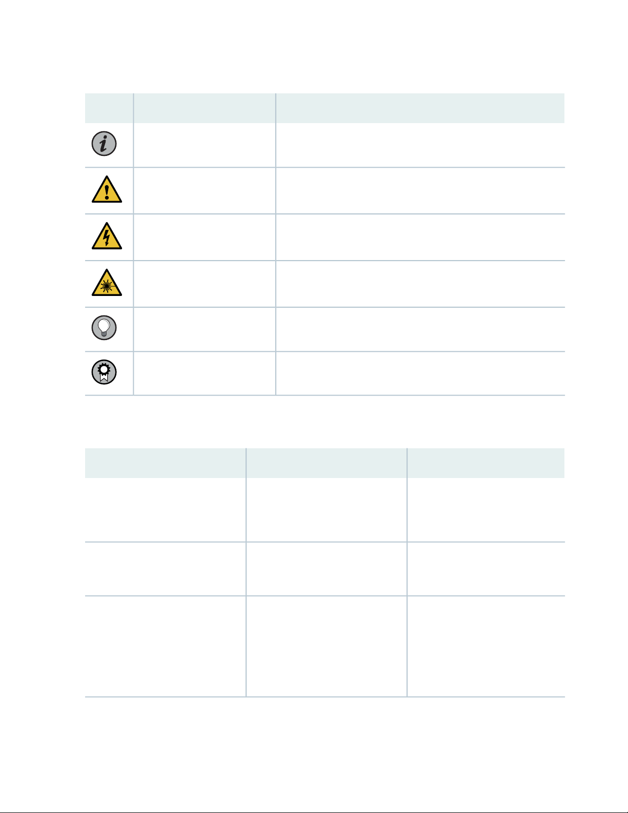
Table 1: Notice Icons
xii
DescriptionMeaningIcon
Indicates important features or instructions.Informational note
Caution
Indicates a situation that might result in loss of data or hardware
damage.
Alerts you to the risk of personal injury or death.Warning
Alerts you to the risk of personal injury from a laser.Laser warning
Indicates helpful information.Tip
Alerts you to a recommended use or implementation.Best practice
Table 2 on page xii defines the text and syntax conventions used in this guide.
Table 2: Text and Syntax Conventions
ExamplesDescriptionConvention
Fixed-width text like this
Italic text like this
Represents text that you type.Bold text like this
Represents output that appears on
the terminal screen.
Introduces or emphasizes important
•
new terms.
Identifies guide names.
•
Identifies RFC and Internet draft
•
titles.
To enter configuration mode, type
the configure command:
user@host> configure
user@host> show chassis alarms
No alarms currently active
A policy term is a named structure
•
that defines match conditions and
actions.
Junos OS CLI User Guide
•
RFC 1997, BGP Communities
•
Attribute
Page 13

Table 2: Text and Syntax Conventions (continued)
xiii
ExamplesDescriptionConvention
Italic text like this
Text like this
< > (angle brackets)
| (pipe symbol)
Represents variables (options for
which you substitute a value) in
commands or configuration
statements.
Represents names of configuration
statements, commands, files, and
directories; configuration hierarchy
levels; or labels on routing platform
components.
variables.
Indicates a choice between the
mutually exclusive keywords or
variables on either side of the symbol.
The set of choices is often enclosed
in parentheses for clarity.
Configure the machine’s domain
name:
[edit]
root@# set system domain-name
domain-name
To configure a stub area, include
•
the stub statement at the [edit
protocols ospf area area-id]
hierarchy level.
The console port is labeled
•
CONSOLE.
stub <default-metric metric>;Encloses optional keywords or
broadcast | multicast
(string1 | string2 | string3)
# (pound sign)
[ ] (square brackets)
Indention and braces ( { } )
; (semicolon)
GUI Conventions
Indicates a comment specified on the
same line as the configuration
statement to which it applies.
Encloses a variable for which you can
substitute one or more values.
Identifies a level in the configuration
hierarchy.
Identifies a leaf statement at a
configuration hierarchy level.
rsvp { # Required for dynamic MPLS
only
community name members [
community-ids ]
[edit]
routing-options {
static {
route default {
nexthop address;
retain;
}
}
}
Page 14
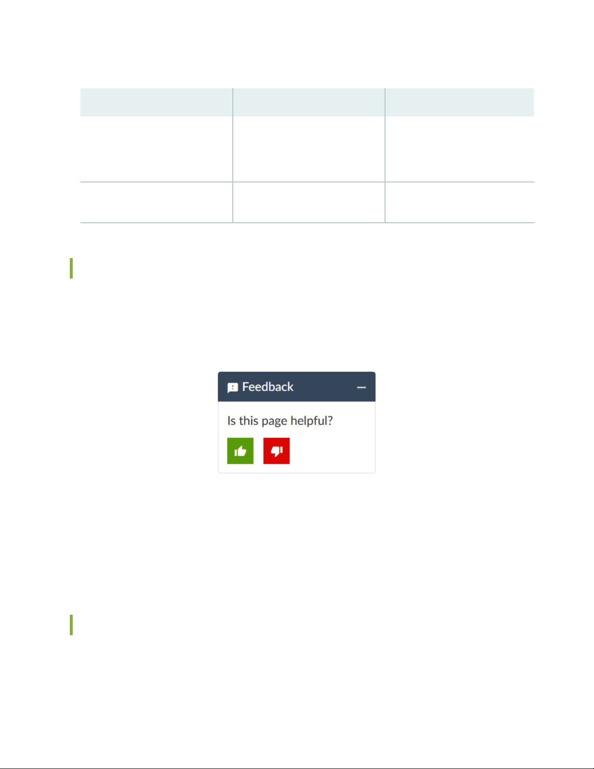
Table 2: Text and Syntax Conventions (continued)
xiv
ExamplesDescriptionConvention
Bold text like this
> (bold right angle bracket)
Represents graphical user interface
(GUI) items you click or select.
Separates levels in a hierarchy of
menu selections.
In the Logical Interfaces box, select
•
All Interfaces.
To cancel the configuration, click
•
Cancel.
In the configuration editor hierarchy,
select Protocols>Ospf.
Documentation Feedback
We encourage you to provide feedback so that we can improve our documentation. You can use either
of the following methods:
Online feedback system—Click TechLibrary Feedback, on the lower right of any page on the Juniper
•
Networks TechLibrary site, and do one of the following:
Click the thumbs-up icon if the information on the page was helpful to you.
•
Click the thumbs-down icon if the information on the page was not helpful to you or if you have
•
suggestions for improvement, and use the pop-up form to provide feedback.
E-mail—Send your comments to techpubs-comments@juniper.net. Include the document or topic name,
•
URL or page number, and software version (if applicable).
Requesting Technical Support
Technical product support is available through the Juniper Networks Technical Assistance Center (JTAC).
If you are a customer with an active Juniper Care or Partner Support Services support contract, or are
Page 15

covered under warranty, and need post-sales technical support, you can access our tools and resources
online or open a case with JTAC.
JTAC policies—For a complete understanding of our JTAC procedures and policies, review the JTAC User
•
Guide located at https://www.juniper.net/us/en/local/pdf/resource-guides/7100059-en.pdf.
Product warranties—For product warranty information, visit https://www.juniper.net/support/warranty/.
•
JTAC hours of operation—The JTAC centers have resources available 24 hours a day, 7 days a week,
•
365 days a year.
Self-Help Online Tools and Resources
For quick and easy problem resolution, Juniper Networks has designed an online self-service portal called
the Customer Support Center (CSC) that provides you with the following features:
Find CSC offerings: https://www.juniper.net/customers/support/
•
Search for known bugs: https://prsearch.juniper.net/
•
xv
Find product documentation: https://www.juniper.net/documentation/
•
Find solutions and answer questions using our Knowledge Base: https://kb.juniper.net/
•
Download the latest versions of software and review release notes:
•
https://www.juniper.net/customers/csc/software/
Search technical bulletins for relevant hardware and software notifications:
•
https://kb.juniper.net/InfoCenter/
Join and participate in the Juniper Networks Community Forum:
•
https://www.juniper.net/company/communities/
Create a service request online: https://myjuniper.juniper.net
•
To verify service entitlement by product serial number, use our Serial Number Entitlement (SNE) Tool:
https://entitlementsearch.juniper.net/entitlementsearch/
Creating a Service Request with JTAC
You can create a service request with JTAC on the Web or by telephone.
Visit https://myjuniper.juniper.net.
•
Call 1-888-314-JTAC (1-888-314-5822 toll-free in the USA, Canada, and Mexico).
•
For international or direct-dial options in countries without toll-free numbers, see
https://support.juniper.net/support/requesting-support/.
Page 16

1
CHAPTER
Overview
Optical ILA System Overview | 17
Optical ILA Chassis | 21
Optical ILA Cooling System Description | 29
Optical ILA Power System | 31
Page 17

Optical ILA System Overview
IN THIS SECTION
Optical Inline Amplifier Description | 17
Optical ILA Hardware Component Overview | 19
Optical ILA Component Redundancy | 20
Optical ILA Field-Replaceable Units | 20
Optical Inline Amplifier Description
17
IN THIS SECTION
Front Panel | 18
FRU Panel | 19
The Juniper Networks Optical Inline Amplifier is a stand-alone erbium-doped fiber amplifier (EDFA) with
dual AC or DC power supplies. The optical inline amplifier (ILA) supports bidirectional optical inline
amplification. The optical ILA provides periodic amplification of a dense wavelength-division multiplexing
(DWDM) signal to enable long-distance transmission as it propagates along the fiber-optic cable. Optical
ILAs are typically placed between 50 miles (80 km) and 62 miles (100 km) apart along the length of the
fiber. They are used in conjunction with the integrated photonic line cards (IPLCs) that are installed in the
Juniper Networks PTX3000 Packet Transport Routers. An optical ILA connects to an IPLC through the
LINE IN and LINE OUT LC port connectors on the front panel. It also connects to other optical ILAs through
the same LC port connectors.
The optical ILA operates with redundant hot-swappable pluggable power supplies that are either AC or
DC. The optical ILA can be managed by using Connectivity Services Director (CSD), or by using the CLI
console commands. The optical ILA does not run the Juniper Networks Junos operating system (Junos
OS).
Starting with Junos OS release 17.1, you can control and manage optical inline amplifiers (ILA) over the
optical supervisory channel (OSC) of the PTX3000 integrated photonic line system. For information about
Page 18
managing the ILAs over the OSC of the the IPLCs, see the Integrated Photonic Line Card (IPLC) System User
Guide.
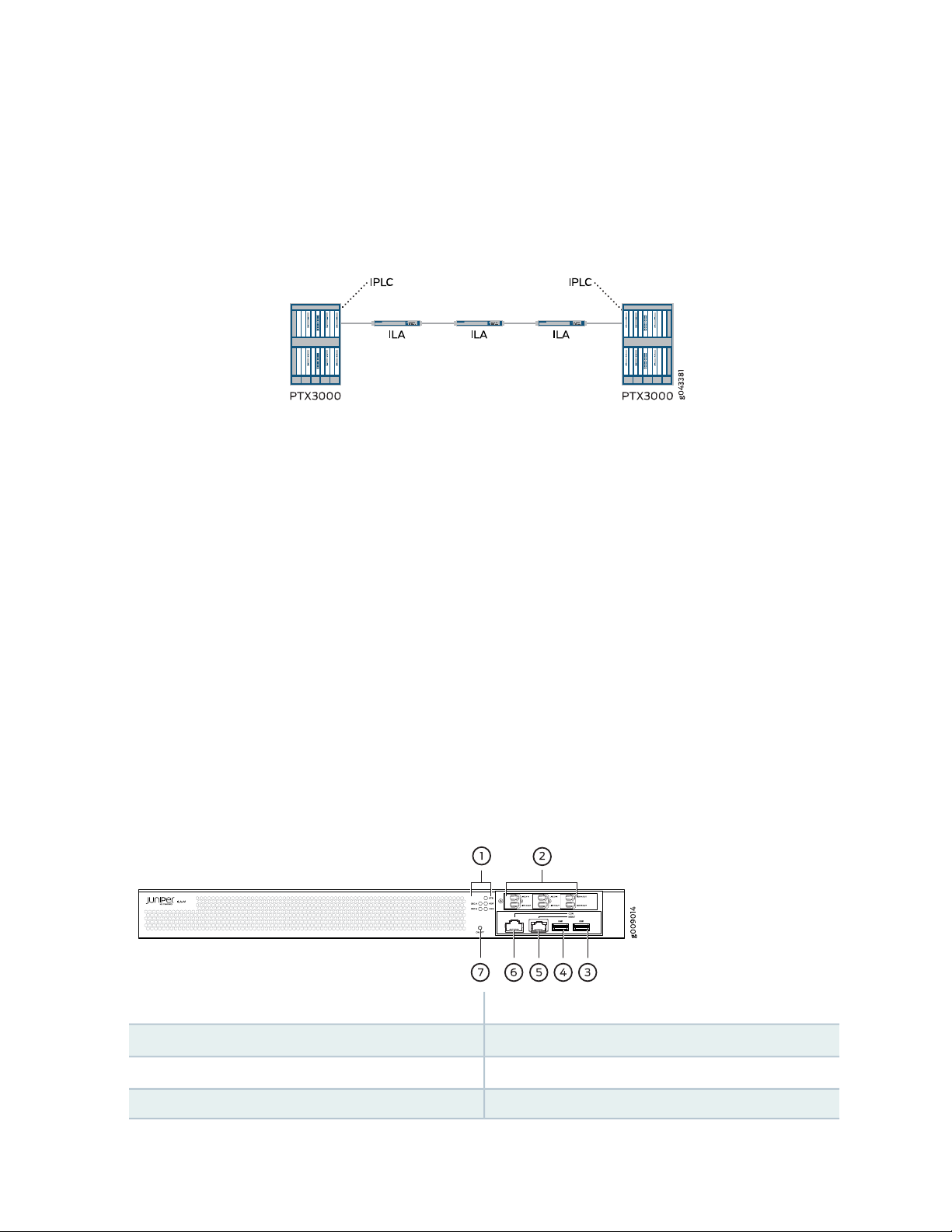
Figure 1 on page 18 shows a point-to-point configuration with the optical ILA and IPLC.
Figure 1: Point-to-Point Configuration
In this example, the optical ILA is connected to the IPLC in the PTX3000 chassis, which is connected to
compatible PICs in the same chassis through the add and drop ports. The multiplexed wavelengths from
the IPLC are amplified and transmitted in a single fiber toward the line (through the Line OUT port on the
IPLC), which is connected to the optical ILA (through the LINE IN port on the ILA). Based on the distance,
you can have multiple ILAs connected. In this example, there are three ILAs to enable long-distance
transmission.
18
For more information about the IPLCs, see the PTX3000 Packet Transport Router Hardware Guide. For
information about configuring the IPLCs, see the Integrated Photonic Line Card (IPLC) System User Guide.
Front Panel
The front panel of the optical ILA contains six LC port connectors, the ON/OFF button, the console and
management ports, the system status LEDs, and the USB ports. Figure 2 on page 18 shows the front panel
of the optical ILA.
Figure 2: Optical ILA Front Panel
5—1— Management (MGMT) Ethernet portStatus LEDs
6—2— Console (CON) portLC port connectors
4—USB (USB) port
7—3— On/off button (ON/OFF)USB (USB) port
Page 19
FRU Panel
The field-replaceable unit (FRU) panel of the optical ILA contains the fan modules and power supplies for
the optical ILA. Figure 3 on page 19 shows the FRU panel on the optical ILA.
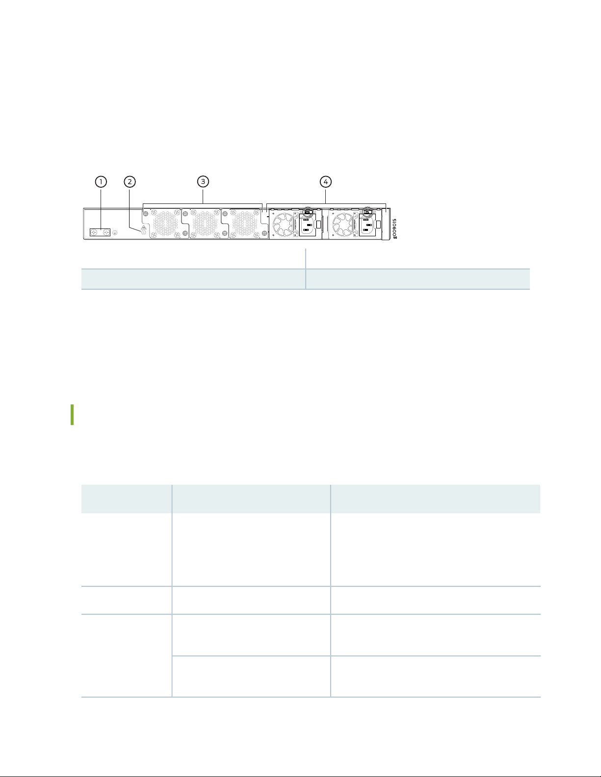
Figure 3: Optical ILA FRU Panel
3—1— Fan modulesGrounding points
4—2— Power suppliesESD point
The cooling system in an optical ILA consists of three 12.4-W fan modules. These fan modules can be
hot-swapped—you do not need to power off the optical ILA or disrupt the functioning of the optical ILA
to replace a fan module. The optical ILA has two 150-W power supplies, either AC or DC depending on
your configuration. The power supplies need to be both AC or both DC. Only one power supply is required
to power the device, while the second power supply provides redundancy.
19
Optical ILA Hardware Component Overview
Table 3 on page 19 describes the hardware components of the optical ILA.
Table 3: Optical ILA Hardware Components
DescriptionSpare Model NumberComponent
Chassis
PTX-ILA-M-DC
PTX-ILA-M-CHAS
JPSU-150-AC-AFOPower supplies
JPSU-150-DC-AFO
“Optical ILA Chassis Description” on page 22PTX-ILA-M-AC
“Optical ILA Cooling System Description” on page 29FAN-ILA-SFan module
“Optical ILA AC Power Supply Description” on
page 31
“Optical ILA DC Power Supply Description” on
page 32
Page 20
Optical ILA Component Redundancy
The following hardware components provide redundancy on the optical ILA models:
Cooling system—The optical ILA has three fan modules. Each fan module is a redundant unit containing
•
one fan. If a fan module fails and the remaining fan modules are unable to keep the optical ILA within
the desired temperature thresholds, chassis alarms are raised and the optical ILA can shut down.
The optical ILA ships with two power supplies that provide 1+1 redundancy. If one power supply fails
•
or is removed, the second power supply balances the electrical load without interruption and still provides
1+1 redundancy while the failing power supply is replaced.
Optical ILA Field-Replaceable Units
Field-replaceable units (FRUs) are components that you can replace at your site. The optical ILA FRUs are
hot-removable and hot-insertable—you can remove and replace them without powering off the optical
ILA or disrupting the optical ILA function.
20
CAUTION: Replace a failed fan module with a new fan module within 30 seconds of
removal to prevent chassis overheating.
Table 4 on page 20 lists the FRUs for the optical ILA and actions to take before removing them.
Table 4: Required Actions Before Removing a FRU from the Optical ILA
Required Actions Before RemovalFRU
Power supplies (2)
Figure 4 on page 21 shows the FRU panel on an optical ILA.
Disconnect the AC power and remove the AC power cord or cable for the power supply
unit.
Disconnect the DC power and remove the power connector.
NOTE: You need a minimum of one powered power supply for the optical ILA to operate
properly.
None.Fan modules (3)
Page 21
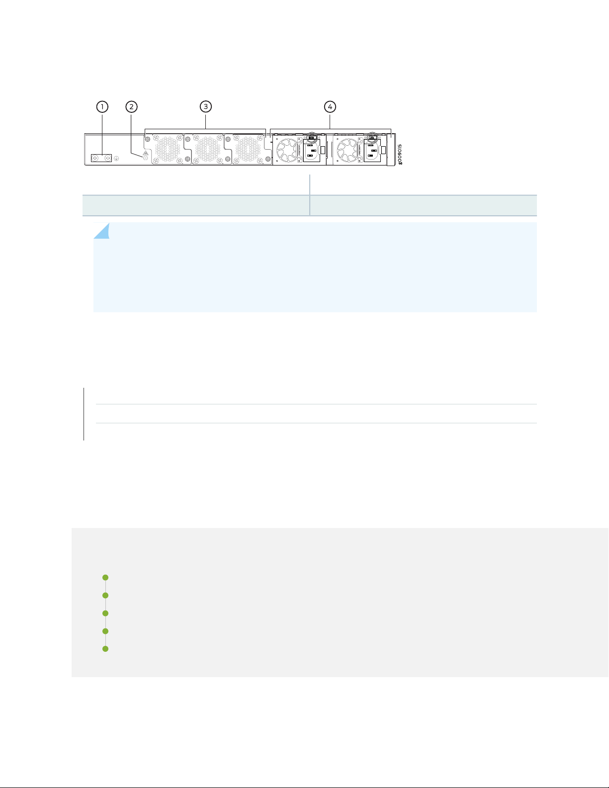
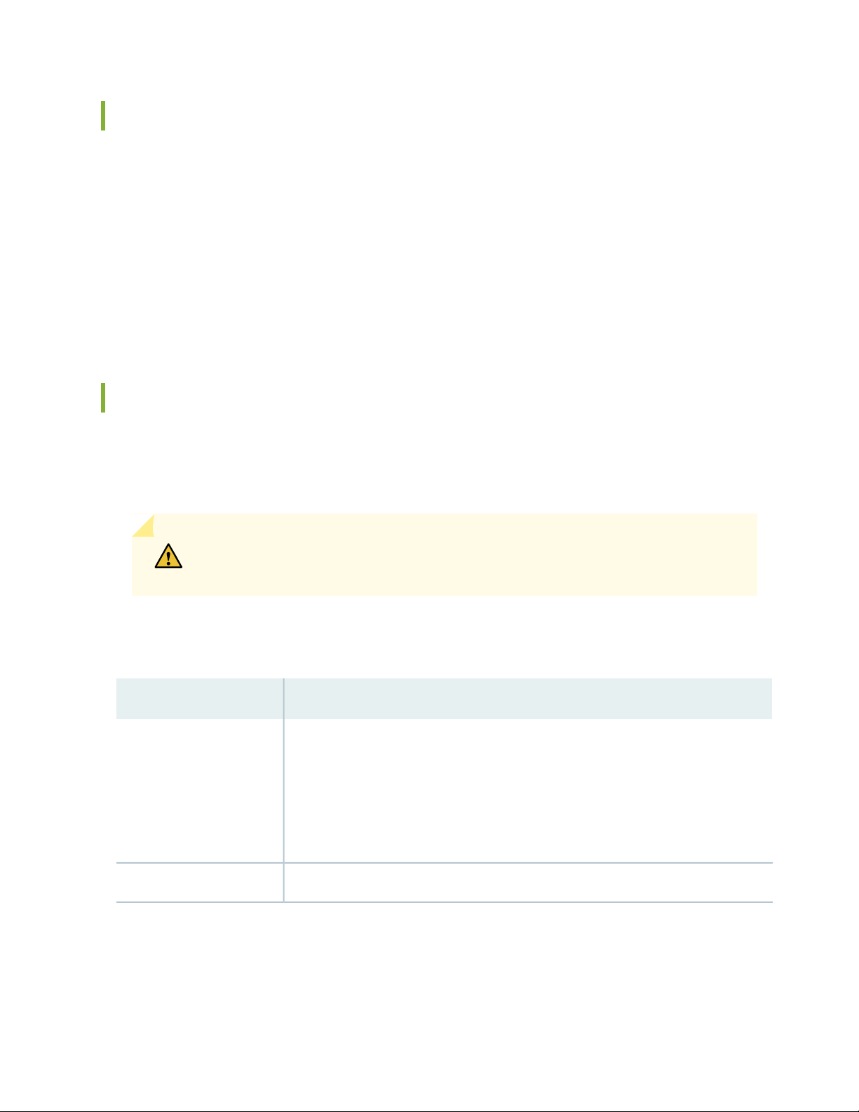
Figure 4: Optical ILA FRU Panel
3—1— Fan modulesGrounding
4—2— Power suppliesESD point
NOTE: If you have a Juniper Care service contract, register any addition, change, or upgrade of
hardware components at https://www.juniper.net/customers/support/tools/updateinstallbase/.
Failure to do so can result in significant delays if you need replacement parts. This note does
not apply if you replace existing components with the same type of component.
21
RELATED DOCUMENTATION
Optical ILA AC Power Supply Description | 31
Optical ILA DC Power Supply Description | 32
Optical ILA Cooling System Description | 29
Optical ILA Chassis
IN THIS SECTION
Optical ILA Chassis Description | 22
Optical ILA Front Panel and FRU Panel | 22
Optical ILA Chassis Status LEDs | 24
Optical ILA Management Panel | 26
Optical ILA Management Port LEDs | 28
Page 22

Optical ILA Chassis Description
The optical ILA chassis is a rigid sheet metal structure that houses all the other hardware components.
The chassis measures 1.72 in. (4.36 cm) high, 9.6 in. (24.4 cm) deep, and 17.24 in. (43.8 cm) wide. The
chassis can be installed in racks or cabinets.
SEE ALSO
Optical Inline Amplifier Description | 17
Optical ILA Front Panel and FRU Panel
22
IN THIS SECTION
Front Panel | 22
FRU Panel | 23
The front panel of the optical ILA contains six LC port connectors, the ON/OFF button, the console and
management ports, the system status LEDs, and the USB ports. The field-replaceable unit (FRU) panel of
the optical ILA contains the fan modules and power supplies for the optical ILA.
Front Panel
Figure 5 on page 23 shows the front panel of the optical ILA.
Page 23
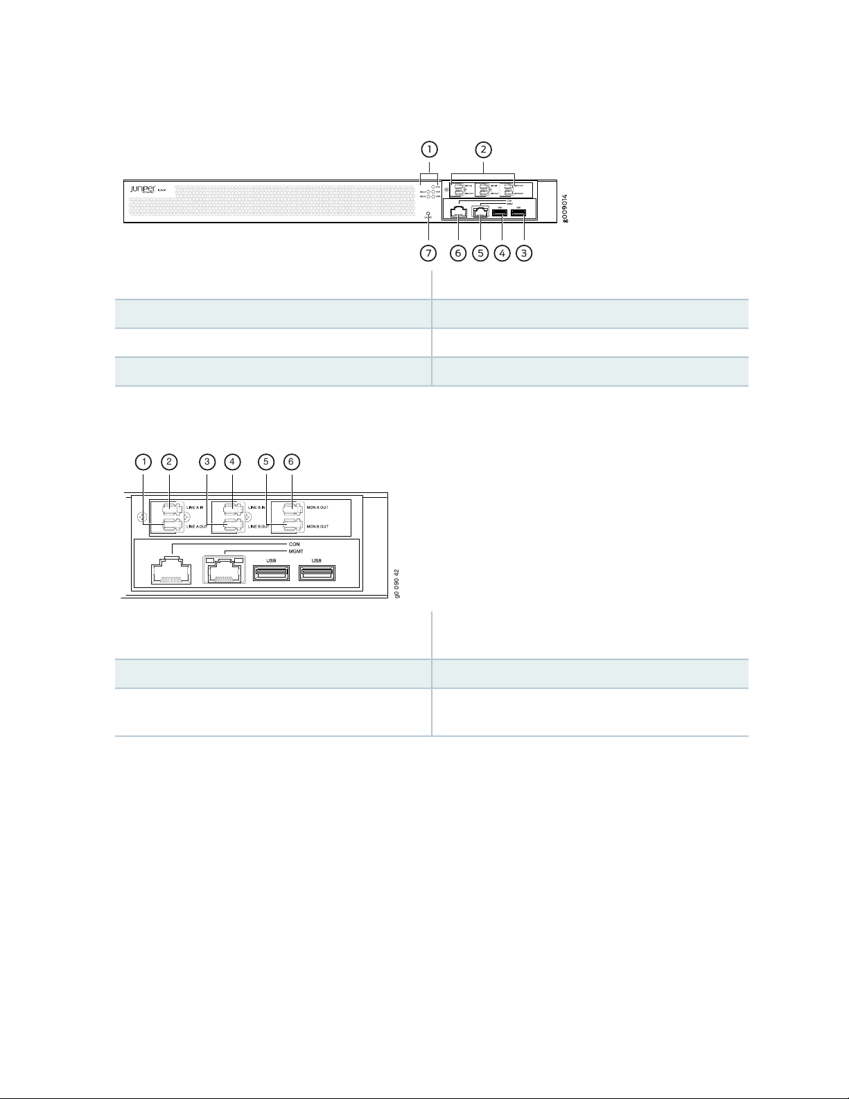
Figure 5: Optical ILA Front Panel
g0 0 90 42
1 2 3 4 5 6
4—USB (USB) port
Figure 6: LC Ports
23
5—1— Management (MGMT) portStatus LEDs
6—2— Console (CON) portLC port connectors
7—3— On/off button (ON/OFF)USB (USB) port
(LINE A OUT)
(LINE B OUT)
The LC ports on the optical ILA have line interfaces toward the optical network (LINE IN and LINE OUT).
The optical ILA is bidirectional—with directions east to west and west to east. There are two optical ports
per direction (two LINE IN ports, two LINE OUT ports, and two (MON) ports for monitoring). See
Figure 6 on page 23.
FRU Panel
Figure 7 on page 24 shows the FRU panel on the optical ILA.
4—1— Input line B (LINE B IN)Output line A—for example, east to west direction
5—2— Monitor output line B (MON B OUT)Input line A (LINE A IN)
6—3— Monitor output line A (MON A OUT)Output line B–for example, west to east direction
Page 24
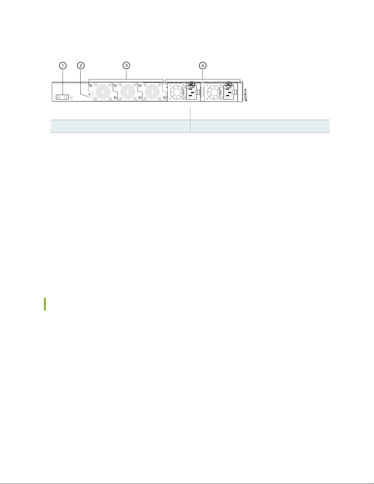
Figure 7: Optical ILA FRU Panel
3—1— Fan modulesGrounding points
4—2— Power suppliesESD point
The cooling system in an optical ILA consists of three 12.4-W fan modules. The fan modules can be
hot-swapped—you do not need to power off the optical ILA or disrupt the optical ILA function to replace
a fan module.
The optical ILA has two 150-W power supplies, either AC or DC depending on your configuration. The
power supplies need to be both AC or both DC—you cannot mix AC and DC power supplies in the same
chassis. Only one power supply is required to power the device, while the second power supply provides
redundancy. When the optical ILA has both power supplies installed and connected to power, the device
has full power redundancy. If a power supply fails or is removed, another power supply balances the
electrical load without interruption. Each power supply provides 12 VDC output with a standby voltage
of 12 VDC. The power supplies can be hot-swapped—you do not need to power off the optical ILA or
disrupt the optical ILA function to replace a power supply.
24
For more information about the components on the FRU panel, see “Optical ILA Cooling System Description”
on page 29, “Optical ILA AC Power Supply Description” on page 31, and “Optical ILA DC Power Supply
Description” on page 32.
Optical ILA Chassis Status LEDs
The optical ILA has five status LEDs on the front panel of the chassis (see Figure 8 on page 25)—two optical
supervisory channel (OSC) status LEDs (OSC A and OSC B), a system status LED (SYS), an alarm LED (ALM),
and a power LED (PWR). The OSC is a separate channel that carries overhead information for network
management purposes. The OSC, which is an important section in every DWDM system, is a separate
channel that carries overhead information for network purposes. For instance, it carries data between
sites for monitoring and controlling specifications in the system.
Page 25
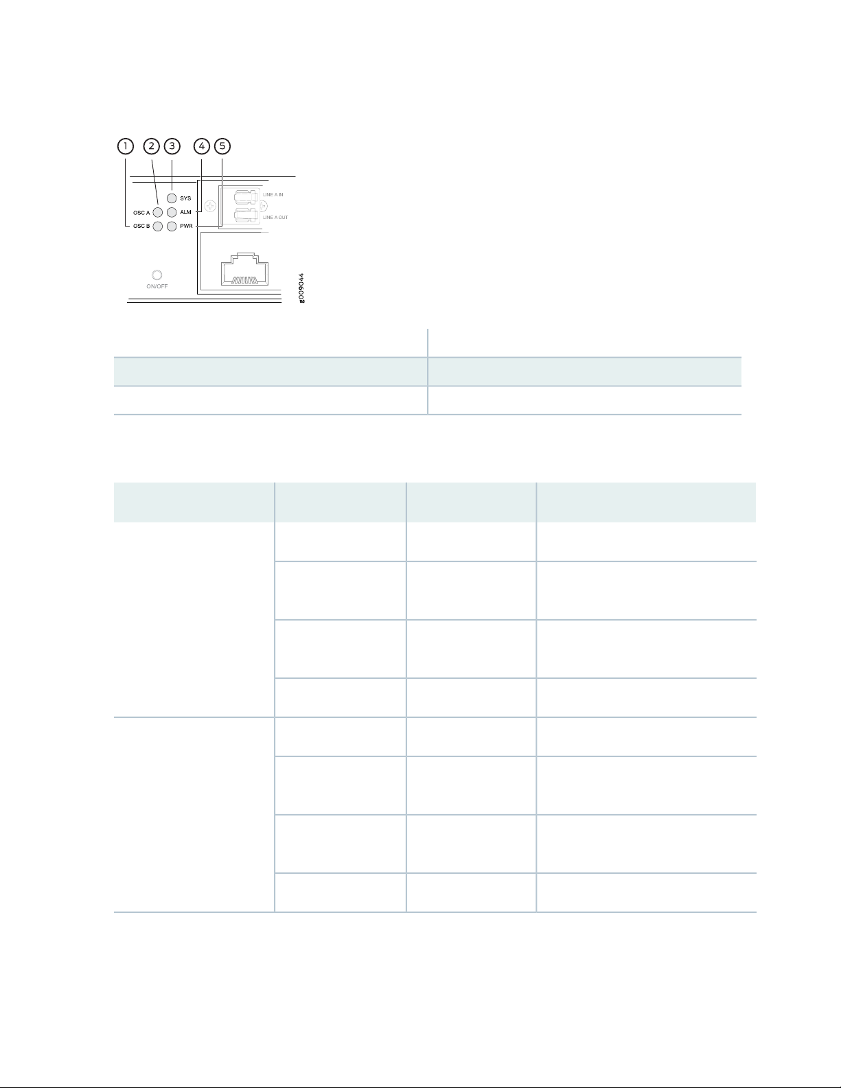
Figure 8: Chassis Status LEDs on an Optical ILA
4—1— Alarm (ALM) LEDOSC B status (OSC B) LED
5—2— Power (PWR) LEDOSC A status (OSC A) LED
3—System status (SYS) LED
Table 5 on page 25 describes the chassis status LEDs on an optical ILA.
25
Table 5: Optical ILA Chassis Status LEDs
DescriptionStateColorName
The power is off.OffUnlitOSC A status (OSC A) LED
On steadilyRed
On steadilyAmber
On steadilyRed
On steadilyAmber
No OSC signal is received from the
downstream device.
OSC signal received from the upstream
device indicates a fault.
OSC signal is communicating normally.On steadilyGreen
The power is off.OffUnlitOSC B status (OSC B) LED
No OSC signal is received from the
downstream device.
OSC signal received from the upstream
device indicates a fault.
OSC signal is communicating normally.On steadilyGreen
Page 26

Table 5: Optical ILA Chassis Status LEDs (continued)
26
DescriptionStateColorName
OffUnlitSystem status (SYS) LED
BlinkingGreen
OffUnlitAlarm (ALM) LED
On steadilyRed
On steadilyAmber
The power is off, or the optical ILA is
not connected to any power source.
The optical ILA software has booted.On steadilyGreen
The optical ILA is active and is
communicating with upstream and
downstream network elements.
The optical ILA is off, or there is no
alarm.
A major hardware fault has occurred,
such as a temperature alarm or a power
or pump failure, and the unit has
halted. The CLI is still accessible.
A minor alarm has occurred, such as a
software error.
The optical ILA is operating properly.SolidGreen
OffUnlitPower (PWR)
On steadilyAmber
On steadilyGreen
The optical ILA is powered off or there
is no power to the device.
The optical ILA is powered by a single
power supply. The second power
supply is either missing or not
connected to a power source.
The optical ILA is powered with two
redundant power supplies.
Optical ILA Management Panel
The optical ILA management panel is found on the front panel (see Figure 9 on page 27).
Page 27

Figure 9: Optical ILA Management Panel Components
3—1— USB port (USB). Debug only.RJ-45 console port (CON) to support RS-232 serial
ports.
4—2— USB port (USB). Debug only.RJ-45 (1000BASE-T) management Ethernet port
(MGMT).
You manage the optical ILA by using the command-line interface (CLI), which is accessible through the
console and out-of-band management ports on the management panel. In addition, the front panel has
system status LEDs (see Table 4 in “Optical ILA Chassis Status LEDs” on page 24) that alert you to minor
or major alarms or other issues with the amplifier. Figure 9 on page 27 shows the management panel in
detail.
27
You can also manage the optical ILA through Connectivity Services Director (CSD), which is a Junos Space
application developed to manage the optical functionality provided by optical ILAs and integrated photonic
line cards (IPLCs) that are installed in the PTX3000 routers. CSD is managed over a data communications
network (DCN). CSD presents a topological network view in an intuitive, comprehensive, and cohesive
manner that enables you to visualize optical sites, links, and services and a site view that provides status,
configuration, alarms/faults, and performance monitoring functionality on the optical interfaces. By using
CSD, you can perform the following tasks on an optical ILA:
View the optical interface specifications that are currently applied on the device, such as wavelength
•
and power.
Modify the existing parameters of the optical port to suit your network needs or resolve any alarms
•
caused by certain interface settings.
View the active alarms generated for the optical interface to analyze and resolve the condition that
•
triggered the alarm on the device.
Configure threshold crossing alarms (TCAs) for the optical interface.
•
View the performance monitoring details in statistical and graphical formats for the optical interface.
•
NOTE: See the Connectivity Services Director User Guide for more information.
Page 28
SEE ALSO
Optical ILA CLI System Commands | 71
Optical ILA CLI show Commands | 72
Optical ILA CLI Configuration Commands | 78
Optical ILA CLI Upgrade Commands | 85
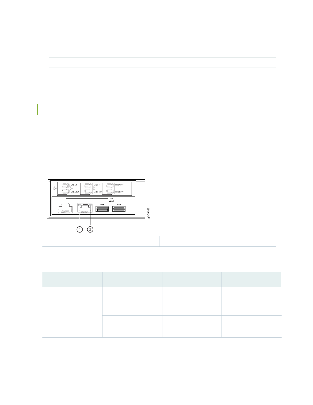
Optical ILA Management Port LEDs
The management port—labeled MGMT—on the optical ILA is located on the management panel.
The management port is an Ethernet port that supports an RJ-45 connector and has separate LEDs for
status and activity. Figure 10 on page 28 shows the location of the LEDs.
Figure 10: Management Port LEDs on the Optical ILA
28
2—1— StatusLink
Table 6 on page 28 describes the RJ-45 management port LEDs.
Table 6: Optical ILA RJ-45 Management Port LEDs
OffUnlitLink
BlinkingYellow
DescriptionStateColorLED
No link is established, there
is a fault, or the link is
down.
A link is established, and
there is link activity.
Page 29

Table 6: Optical ILA RJ-45 Management Port LEDs (continued)
29
DescriptionStateColorLED
Link is down.OffUnlitStatus
Green
RELATED DOCUMENTATION
Optical ILA AC Power Supply Description | 31
Optical ILA DC Power Supply Description | 32
On steadily
Blinking
Optical ILA Cooling System Description
IN THIS SECTION
Fan Modules | 30
Link is up.
There is data activity.
The cooling system in an optical ILA consists of three 12.4-W fan modules installed in the field-replaceable
unit (FRU) panel and two counter-rotating fans housed in each of the power supplies.
In the optical ILA's cooling system, cool air enters through the vents in the front panel and hot air exhausts
through the fans in the FRU panel. This type of airflow is known as airflow out or front-to-back airflow.
When installed, the chassis must be positioned so that the FRUs are next to the hot air exhaust.
NOTE: Under normal operating conditions, the fan modules operate at a moderate speed.
Temperature sensors in the chassis monitor the temperature within the chassis. The system
raises an alarm if a fan module fails or if the ambient temperature inside the chassis rises above
the acceptable range.
Page 30
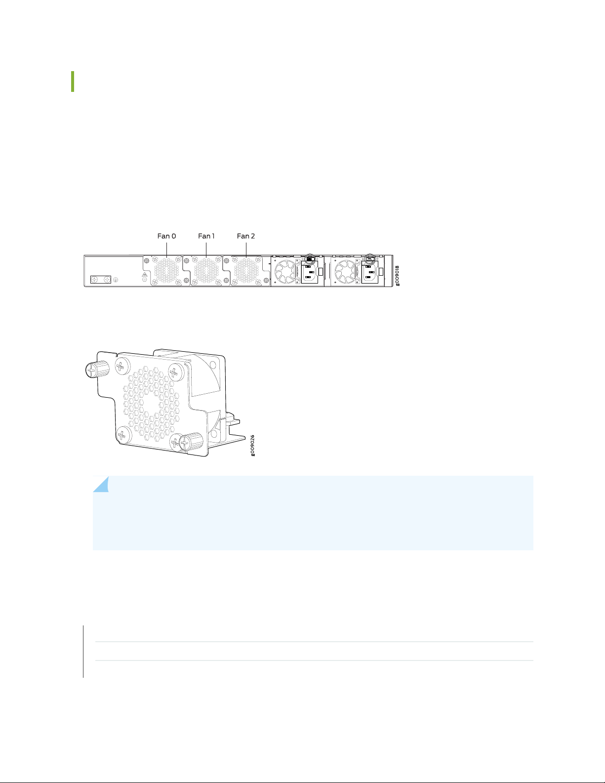
Fan Modules
The fan modules in an optical ILA are hot-removable and hot-insertable FRUs. These fan modules can be
hot-swapped—you do not need to power off the optical ILA or disrupt the optical ILA function to replace
a fan module. The fan module slots are numbered 0 through 2 from left to right when viewing chassis from
the FRU panel side (see Figure 11 on page 30). Figure 12 on page 30 shows the fan module for the optical
ILA. The numbers are located on the top of the chassis.
Figure 11: Fan Numbering
Figure 12: Fan Module
30
NOTE: All three fan modules must be installed for optimal operation of the optical ILA. The
optical ILA continues to operate for a period of 30 seconds during the replacement of the fan
module without thermal shutdown.
RELATED DOCUMENTATION
Prevention of Electrostatic Discharge Damage | 153
Installing a Fan Module in an Optical ILA | 93
Removing a Fan Module from an Optical ILA | 92
Page 31

Optical ILA Power System
IN THIS SECTION
Optical ILA AC Power Supply Description | 31
Optical ILA DC Power Supply Description | 32
Optical ILA Power Supply LEDs | 34
Optical ILA AC Power Specifications | 36
Optical ILA AC Power Cord Specifications | 36
Optical ILA DC Power Specifications | 37
Optical ILA DC Power Cable and Lugs Specifications | 38
Optical ILA Chassis Grounding Cable and Lug Specifications | 39
31
Optical ILA AC Power Supply Description
The AC power supplies in the optical ILA (see Figure 14 on page 32) are hot-removable and hot-insertable
field-replaceable units (FRUs) that you can install without powering off the optical ILA or disrupting the
functioning of the optical ILA. The optical ILA has two AC power supplies. Both the power supplies are
initially installed at the factory. See Figure 13 on page 31 for the power numbering scheme, the power
supply number (0 or 1) is located on the top of the chassis.
Figure 13: Power Supply Numbering
Page 32

Figure 14: AC Power Supply in an Optical ILA
3—1— Power plug connectorPower cord retainer
4—2— Ejector leverHandle
Each of the 150-W power supplies has a single AC input. The power supply provides 12-VDC output with
a standby voltage of 12 VDC. An optical ILA has twice the number of power supplies needed to power all
of the components in the device, which is known as 1+1 redundancy. When the optical ILA has both power
supplies installed and connected to power, the device has full power redundancy. If a power supply fails
or is removed, another power supply balances the electrical load without interruption.
32
The fans in the power supply provide front-to-back airflow, which is also known as airflow out (AFO).
CAUTION: To avoid electrical injury, carefully follow instructions in “Connecting AC
Power to an Optical ILA” on page 63, “Installing an AC Power Supply in an Optical ILA”
on page 98, and “Removing an AC Power Supply from an Optical ILA” on page 96.
NOTE: For more information about power system redundancy, see “Optical ILA Component
Redundancy” on page 20.
Optical ILA DC Power Supply Description
The DC power supplies in the optical ILA (see Figure 15 on page 33) are hot-removable and hot-insertable
field-replaceable units (FRUs) that you can install without powering off the optical ILA or disrupting the
functioning of the optical ILA. The DC version of the optical ILA has two DC power supplies. Both the
power supplies are initially installed at the factory.
Page 33

Figure 15: DC Power Supply in an Optical ILA
3—1— Ejector leverHandle
2—DC terminal
Each of the two 150-W power supplies has a single DC input. The power supply provides 12 VDC output
with a standby voltage of 12 VDC. An optical ILA has twice the number of power supplies needed to power
all of the components in the device, which is known as 1+1 redundancy. When the optical ILA has both
power supplies installed and connected to power, the device has full power redundancy. If a power supply
fails or is removed, the other or second power supply balances the electrical load without interruption.
33
The fans in the power supply provide front-to-back airflow, which is also known as airflow out (AFO).
CAUTION: To avoid electrical injury, carefully follow instructions in “Connecting DC
Power to an Optical ILA” on page 66, “Installing a Power Supply in an Optical ILA” on
page 97, and “Removing a Power Supply from an Optical ILA” on page 95.
NOTE: We recommend that the 48-VDC facility DC source be equipped with a circuit protector
rated at 10 A (–48 VDC) minimum, or as required by local code.
NOTE: We recommend that the 60-VDC facility DC source be equipped with a circuit protector
rated at 5 A (–60 VDC) minimum, or as required by local code.
NOTE: For more information about power system redundancy, see “Optical ILA Hardware
Component Overview” on page 19.
Page 34

Optical ILA Power Supply LEDs
Each optical ILA power supply has two LEDs on the power supply faceplate. Figure 16 on page 34 shows
the location of the LEDs on an optical ILA AC power supply. Figure 17 on page 34 shows the location of
the LEDs on an optical ILA DC power supply.
Figure 16: AC Power Supply LEDs
34
2—1— AC OKDC OK
Figure 17: DC Power Supply LEDs
2—1— DC IN OKDC OUT OK
Use Table 7 on page 35 and Table 8 on page 35 to interpret the state of the power supply LEDs.
Page 35

Table 7: Optical ILA AC Power Supply LED
35
DescriptionStateColorName
There is no power to any of the power supplies.OffUnlitDC OK
The power supply is on standby mode (AC IN present).BlinkingGreen
The power supply is on and operating correctly.On steadily
There is a power supply failure.On steadilyRed
No AC power to this power supply only.Blinking
There is no power to any of the power supplies.OffUnlitAC OK
The power supply output is on and operating correctly.On steadilyGreen
Table 8: Optical ILA DC Power Supply LED
The power supply is on standby mode (AC IN present).On steadily
There is a power supply failure.On steadilyRed
No AC power to this power supply only.Blinking
DescriptionStateColorName
There is no power to the power supplies.OffUnlitDC OUT OK
The power supply is on and operating correctly.On steadilyGreen
The power supply is on standby mode (DC IN present).Blinking
There is a power supply failure.On steadilyRed
There is no DC power to this power supply only.Blinking
Page 36

Table 8: Optical ILA DC Power Supply LED (continued)
Optical ILA AC Power Specifications
36
DescriptionStateColorName
There is no power to the power supplies.OffUnlitDC IN OK
The power supply is on and operating correctly.On steadilyGreen
The power supply is on standby mode (DC IN present).On steadily
There is a power supply failure.On steadilyRed
There is no DC power to this power supply only.Blinking
Table 9 on page 36 describes the AC power specifications for an optical ILA.
Table 9: AC Power Specifications for an Optical ILA
SpecificationItem
Operating range: 100–240 VACAC input voltage
50–60 HzAC input line frequency
AC input current rating
3 A at 100–136 VAC
1.5 A at 180–266 VAC
75 WTypical power consumption
115.5 WMaximum power consumption
Optical ILA AC Power Cord Specifications
Detachable AC power cords are shipped with the chassis if you include them as part of your order. The
coupler is type C13 as described by International Electrotechnical Commission (IEC) standard 60320. The
plug end of the power cord fits into the power source outlet that is standard for your geographical location.
Page 37

NOTE: In North America, AC power cords must not exceed 14.75 feet (approximately 4.5 meters)
in length, to comply with National Electrical Code (NEC) Sections 400-8 (NFPA 75, 5-2.2) and
210-52 and Canadian Electrical Code (CEC) Section 4-010(3). The cords that can be ordered for
the optical ILA are in compliance.
Table 10 on page 37 lists AC power cord specifications provided for each country or region.
Table 10: AC Power Cord Specifications for the Optical ILA
Plug TypeElectrical SpecificationModel NumberCountry
AS/NZ 3112–1993250 VAC, 10 A, 50 HzCBL-GP-JX-PWR-AUAustralia
37
250 VAC, 10 A, 50 HzCBL-GP-JX-PWR-CHChina
and United Kingdom)
Optical ILA DC Power Specifications
Table 11 on page 38 describes the DC power specifications for an optical ILA.
GB2099.1 1996 and
GB1002 1996 (CH1-10P)
CEE (7) VII250 VAC, 10 A, 50 HzCBL-GP-JX-PWR-EUEurope (except Italy
IEC60884-1250 VAC, 10 A, 50 HzCBL-GP-JX-PWR-ITItaly
JIS 8303 and 8306125 VAC, 12 A, 50 Hz or 60 HzCBL-GP-JX-PWR-JPJapan
NEMA 5-15P125 VAC, 10 A, 60 HzCBL-GP-JX-PWR-USNorth America
BS1363250 VAC, 10 A, 50 HzCBL-GP-JX-PWR-UKUnited Kingdom
NOTE: We recommend that the 48 VDC facility DC source be equipped with a circuit breaker
rated at 10 A (–48 VDC) minimum, or as required by local code.
We recommend that the 60-VDC facility DC source be equipped with a circuit protector rated
at 5 A (–60 VDC) minimum, or as required by local code.
Page 38

Table 11: DC Power Specifications for the Optical ILA
38
SpecificationsItem
DC input voltage
Operating voltage range: –40 VDC through
–72 VDC
6 A maximumDC input current rating
75 WTypical power consumption
115.5 WMaximum power consumption
Optical ILA DC Power Cable and Lugs Specifications
IN THIS SECTION
DC Power Cables | 38
DC Power Connector | 39
DC Power Cables
You must supply the DC power cables that meet the specifications in Table 12 on page 38, or as required
by the local code, laws, and standards.
Table 12: DC Power Cable Specifications
SpecificationCable
18-AWG (0.8 mm2) minimumMinimum size cable
12-AWG (3.3 mm2)Maximum size cable
WARNING: For field-wiring connections, use copper conductors only.
Page 39

CAUTION: Before optical ILA installation begins, a licensed electrician must attach a
cable lug to the power cables that you supply. A cable with an incorrectly attached lug
can damage the optical ILA.
CAUTION: You must ensure that power connections maintain the proper polarity.
The power source cables might be labeled (+) and (–) to indicate their polarity. There
is no standard color coding for DC power cables. The color coding used by the external
DC power source at your site determines the color coding for the leads on the power
cables that attach to the terminals on each power supply.
DC Power Connector
39
The accessory box shipped with the optical ILA includes the DC power connector that attaches to the
terminal studs of each power supply.
SEE ALSO
Connecting DC Power to an Optical ILA | 66
Optical ILA DC Power Electrical Safety Guidelines | 155
Optical ILA Chassis Grounding Cable and Lug Specifications
For installations that require a separate grounding conductor to the chassis, the optical ILA must be
adequately grounded before power is connected to ensure proper operation and to meet safety and
electromagnetic interference (EMI) requirements. To ground an optical ILA, connect a grounding cable to
earth ground and then attach it to the chassis grounding points.
WARNING: The device is pluggable type A equipment installed in a restricted-access
location. It has a separate protective earthing terminal provided on the chassis in
addition to the grounding pin of the power supply cord. This separate protective
earthing terminal must be permanently connected to earth ground for installations
that require a separate grounding conductor to the chassis.
Page 40

CAUTION: Before device installation begins, a licensed electrician must attach a cable
lug to the grounding cables that you supply. See “Connecting the Optical ILA Grounding
Cable” on page 62. A cable with an incorrectly attached lug can damage the optical
ILA.
Before connecting the optical ILA to earth ground, review the following information:
A protective earthing terminal bracket is required for connecting the optical ILA to earth ground. This
•
two-holed bracket is attached to the rear of the optical ILA chassis and provides a protective earthing
terminal for the device. The grounding points require two #10-32 UNF screws. The grounding points
are spaced at 0.63 in. (16 mm).
The grounding lug required is a Panduit LCD6-14BH-L or equivalent (not provided). The grounding lug
•
accommodates 14–10 AWG (2–5.3 mm²) stranded wire.
The grounding cable that you provide for an optical ILA must be the same size or heavier than the input
•
wire of each power supply. Minimum recommendations are 14–10 AWG (2–5.3 mm²) stranded wire,
60° C wire, or as permitted by local code.
40
RELATED DOCUMENTATION
Connecting AC Power to an Optical ILA | 63
Connecting DC Power to an Optical ILA | 66
Prevention of Electrostatic Discharge Damage | 153
Page 41

2
CHAPTER
Site Planning, Preparation, and
Specifications
Optical ILA Site Preparation Checklist | 42
Optical ILA Site Guidelines and Requirements | 43
Optical ILA Management Cable Specifications and Pinouts | 49
Page 42

Optical ILA Site Preparation Checklist
The checklist in Table 13 on page 42 summarizes the tasks you need to perform when preparing a site for
an optical ILA installation.
Table 13: Site Preparation Checklist
DatePerformed byFor More InformationItem or Task
Environment
42
Verify that environmental factors such as
temperature and humidity do not exceed the
optical ILA tolerances.
Power
Measure the distance between external power
sources and the optical ILA installation site.
Calculate the power consumption and
requirements.
Rack or Cabinet
Verify that your rack or cabinet meets the
minimum requirements for the installation of
the optical ILA.
“Optical ILA Environmental
Requirements and
Specifications” on page 44
“Optical ILA AC Power
Specifications” on page 36
“DC Power Specifications for
the Optical ILA” on page 38
“Optical ILA Rack
Requirements” on page 46
“Optical ILA Cabinet
Requirements” on page 47
Plan rack or cabinet location, including required
space clearances.
Secure the rack or cabinet to the floor and
building structure.
Cables
“Optical ILA Clearance
Requirements for Airflow and
Hardware Maintenance” on
page 45
Page 43

Table 13: Site Preparation Checklist (continued)
Acquire cables and connectors:
Determine the number of cables needed
•
based on your planned configuration.
Review the maximum distance allowed for
•
each cable. Choose the length of cable based
on the distance between the hardware
components being connected.
Plan the cable routing and management.
RELATED DOCUMENTATION
43
DatePerformed byFor More InformationItem or Task
General Electrical Safety Guidelines and Warnings | 152
Overview of Installing the Optical ILA | 53
Unpacking and Mounting the Optical ILA | 54
Optical ILA Site Guidelines and Requirements
IN THIS SECTION
Optical ILA Environmental Requirements and Specifications | 44
Optical ILA Clearance Requirements for Airflow and Hardware Maintenance | 45
Optical ILA Physical Specifications | 46
Optical ILA Rack Requirements | 46
Optical ILA Cabinet Requirements | 47
Optical Specifications for the Optical ILA | 48
Page 44

Optical ILA Environmental Requirements and Specifications
The optical ILA must be installed in a rack or cabinet. It must be housed in a dry, clean, well-ventilated,
and temperature-controlled environment.
Follow these environmental guidelines:
The site must be as dust-free as possible, because dust can clog air intake vents and filters, reducing the
•
efficiency of the optical ILA cooling system.
Maintain ambient airflow for normal optical ILA operation. If the airflow is blocked or restricted, or if
•
the intake air is too warm, the chassis might overheat, leading to the optical ILA temperature monitor
shutting down the device to protect the hardware components.
Table 14 on page 44 provides the required environmental conditions for normal operation of the optical
ILA .
Table 14: Optical ILA Environmental Tolerances
44
Relative humidity
Temperature
Seismic
ToleranceDescription
No performance degradation up to 6000 feet (1828.8 meters).Altitude
Normal operation ensured in relative humidity range of 5% through 90%,
noncondensing.
Short-term operation ensured in relative humidity range of 5% through
•
93%, noncondensing.
NOTE: As defined in NEBS GR-63-CORE, Issue 3, short-term events can
be up to 96 hours in duration but not more than 15 days per year.
Normal operation ensured in temperature range of 41° F (5° C) through
•
104 F (40° C). Short-term temperature is 23° F (–5° C) through 131 F
(55° C)
Nonoperating storage temperature in shipping container: –40°F (40° C)
•
through 158° F (70° C).
Designed to comply with Zone 4 earthquake requirements per NEBS
GR-63-CORE, Issue 3.
NOTE: Install the optical ILA only in restricted-access areas, such as dedicated equipment rooms
and equipment closets, in accordance with Articles 110-16, 110-17, and 110-18 of the National
Electrical Code, ANSI/NFPA 70.
Page 45

Optical ILA Clearance Requirements for Airflow and Hardware Maintenance
When planning the site for an optical ILA installation, you must allow sufficient clearance around the
installed chassis (see Figure 18 on page 45).
Figure 18: Clearance Requirements for Airflow and Hardware Maintenance for an Optical ILA
45
Follow these guidelines:
For the cooling system to function properly, the airflow around the chassis must be unrestricted. See
•
“Optical ILA Cooling System Description” on page 29 for more information about the airflow through
the chassis.
If you are mounting an optical ILA in a rack or cabinet with other equipment, ensure that the exhaust
•
from other equipment does not blow into the intake vents of the optical ILA chassis.
You must leave at least 24 in. (61 cm) both in front of and behind the optical ILA. For service personnel
•
to remove and install hardware components, you must leave adequate space at the front and back of
the optical ILA. NEBS GR-63 recommends that you allow at least 30 in. (76.2 cm) in front of the rack or
cabinet and 24 in. (61 cm) behind the rack or cabinet.
Page 46

Optical ILA Physical Specifications
Table 15 on page 46 lists the physical specifications for the optical ILA chassis and components.
Table 15: Physical Specifications for the Optical ILA
Model
Numbers
WeightDepthWidthHeightFans and Power
46
PTX-ILA-M-AC
PTX-ILA-M-DC
3 fan modules and 2
AC power supplies
installed
3 fan modules and 2
DC power supplies
installed
1.72 in.
(4.36 cm)
1.72 in.
(4.36 cm)
17.24 in.
(43.8 cm)
17.4 in.
(44.19 cm)
9.6 in. (24.4 cm)
without handles for
fans or power
supplies.
9.8 in. (24.89 cm)
without handles for
fans or power
supplies.
Optical ILA Rack Requirements
The optical ILA chassis is designed to be installed in two-post or four-post racks.
Rack requirements consist of:
Rack type
•
With
field-replaceable
units (FRUs)
installed: 11.7 lb
(5.30 kg)
With FRUs installed:
11.8 lb (5.35 kg)
Mounting bracket hole spacing
•
Rack size and strength
•
Table 16 on page 46 provides the rack requirements and specifications for the optical ILA.
Table 16: Rack Requirements for the Optical ILA
GuidelinesRack Requirement
Rack type: two-post or
four-post
Use a two-post or four-post rack that provides bracket patterns spaced at 1-U (1.75 in.
or 4.45 cm) increments and that meets the size and strength requirements to support the
weight.
A U is the standard rack unit defined in Cabinets, Racks, Panels, and Associated Equipment
(document number EIA-310–D) published by the Electronics Components Industry
Association (http://www.ecianow.org/).
Page 47

Table 16: Rack Requirements for the Optical ILA (continued)
GuidelinesRack Requirement
47
Mounting bracket hole
spacing
Rack size and strength
Rack connection to
building structure
The holes in the mounting brackets are spaced at 1.25 in. (or 3.17 cm), so that the optical
ILA can be mounted in any rack that provides holes spaced at that distance.
Ensure that the rack complies with the standards for a 19-in. or 23-in. rack as defined
•
in Cabinets, Racks, Panels, and Associated Equipment (document number EIA-310–D)
published by the Electronics Components Industry Association
(http://www.ecianow.org/).
Ensure that the rack rails are spaced widely enough to accommodate the optical ILA
•
chassis. The outer edges of the front-mounting brackets extend the width to 19 in.
(48.26 cm).
Ensure that the front and rear rack rails are spaced between 28 in. (71.1 cm) and 36 in.
•
(91.4 cm) front-to-back.
Ensure that the rack is strong enough to support the weight of the optical ILA.
•
Ensure that the spacing of rails and adjacent racks allows for proper clearance around
•
the optical ILA and rack.
Secure the rack to the building structure.
•
If earthquakes are a possibility in your geographical area, secure the rack to the floor.
•
Secure the rack to the ceiling brackets as well as wall or floor brackets for maximum
•
stability.
SEE ALSO
Maintenance and Operational Safety Guidelines and Warnings | 144
Optical ILA Cabinet Requirements
You can mount optical ILA models in a cabinet that contains a two-post 19-in. or four-post rack as defined
in Cabinets, Racks, Panels, and Associated Equipment (document number EIA-310-E) published by the
Electronics Components Industry Association (http://www.ecianow.org/).
Cabinet requirements consist of:
Cabinet size and clearance
•
Cabinet airflow requirements
•
Table 17 on page 48 provides the cabinet requirements and specifications for the optical ILA.
Page 48

Table 17: Cabinet Requirements for the Optical ILA
GuidelinesCabinet Requirement
48
Cabinet size and clearance
Cabinet airflow requirements
The minimum cabinet size for accommodating an optical ILA is 18 in. (45.7 cm)
deep. Large cabinets improve airflow and reduce the chance of overheating.
NOTE: The DC version of the optical ILA conforms to the ETSI 300 mm
cabinets.
When you mount the optical ILA in a cabinet, ensure that ventilation through
the cabinet is sufficient to prevent overheating.
Ensure that the cool air supply you provide through the cabinet adequately
•
dissipates the thermal output of the optical ILA (and other installed
equipment).
Ensure that the cabinet allows the hot exhaust air of the chassis to exit
•
the cabinet without recirculating into the optical ILA. An open cabinet
(without a top or doors) that employs hot air exhaust extraction from the
top allows the best airflow through the chassis. If the cabinet contains a
top or doors, perforations in these elements assist with removing the hot
air exhaust.
Install the optical ILA in the cabinet in a way that maximizes the open space
•
on the field-replaceable unit (FRU) side of the chassis. This maximizes the
clearance for critical airflow. The optical ILA exhausts hot air through the
fans and power supplies.
Route and dress all cables to minimize the blockage of airflow to and from
•
the optical ILA.
Ensure that the spacing of rails and adjacent cabinets allows for the proper
•
clearance around the optical ILA and cabinet.
Optical Specifications for the Optical ILA
Table 18 on page 48 provides the optical specifications for the optical ILA.
Table 18: Optical Specifications
MaximumMinimumConfigurationsParameter
9.8 dBm–15.2 dBmLoaded system (96 channels)Input power range
–10 dBm–35 dBmSingle channel
Page 49

Table 18: Optical Specifications (continued)
range
49
MaximumMinimumConfigurationsParameter
19.8 dBmLoaded system (96 channels)Signal output power
0 dBmSingle channel
30 dB10 dBOutput gain tilt equal to 0 dBGain range (standard)
Gain range (extended)
0
RELATED DOCUMENTATION
Connecting the Optical ILA Grounding Cable | 62
Unpacking and Mounting the Optical ILA | 54
35 dB30 dBOutput gain tilt not equal to
Optical ILA Management Cable Specifications and Pinouts
IN THIS SECTION
Cable Specifications for Console and Management Connections for the Optical ILA | 49
Management Port Connector Pinouts for the Optical ILA | 50
Console Port Connector Pinouts for the Optical ILA | 51
Cable Specifications for Console and Management Connections for the Optical ILA
Table 19 on page 50 lists the specifications for the cables that connect the optical ILA to a management
device.
Page 50

Table 19: Cable Specifications for Console and Management Connections for the Optical ILA
50
Port on optical
ILA
Console (CON) port
Management
(MGMT) port
RS-232 (EIA-232) serial
cable
Category 5 cable or
equivalent suitable for
1000BASE-T operation
One 7-foot (2.13-meter)-long
RJ-45 patch cable and RJ-45
to DB-9 adapter
One 7-foot (2.13-meter)-long
RJ-45 patch cable
Maximum
LengthCable SuppliedCable Specification
(2.13 meters)
(100 meters)
Device
Receptacle
RJ-457 feet
RJ-45328 feet
Management Port Connector Pinouts for the Optical ILA
The 1000BASE-T management port (labeled MGMT) uses an RJ-45 connector to connect to a management
device for out-of-band management.
Table 20 on page 50 provides the pinout information of the RJ-45 management port connector. An RJ-45
cable is supplied with the optical ILA.
Table 20: RJ-45 Management Port Connector Pinouts for the Optical ILA
DescriptionSignalPin
Transmit/receive data pair 1TRP1+1
Transmit/receive data pair 1TRP1–2
Transmit/receive data pair 2TRP2+3
Transmit/receive data pair 3TRP3+4
Transmit/receive data pair 3TRP3–5
Transmit/receive data pair 2TRP2–6
Transmit/receive data pair 4TRP4+7
Transmit/receive data pair 4TRP4–8
Page 51

Console Port Connector Pinouts for the Optical ILA
The console port (labeled CON) is an RS-232 serial interface that uses an RJ-45 connector to connect to
a console management device. The default baud rate for the console port is 9600 baud.
Table 21 on page 51 provides the pinout information for the RJ-45 console connector. An RJ-45 cable
and RJ-45 to DB-9 adapter are supplied with the optical ILA.
NOTE: If your laptop or PC does not have a DB-9 plug connector pin and you want to connect
your laptop or PC directly to an optical ILA, use a combination of the RJ-45 cable and RJ-45 to
DB-9 adapter supplied with the device and a USB to DB-9 plug adapter. You must provide the
USB to DB-9 plug adapter.
Table 21: Console Port Connector Pinouts for the Optical ILA
51
RELATED DOCUMENTATION
DescriptionSignalPin
ReservedReserved1
Data terminal ready/ReservedReserved2
Transmit dataTxD Output3
Signal groundSignal Ground4
Signal groundSignal Ground5
Receive dataRxD Input6
ReservedReserved7
ReservedReserved8
Management Port LEDs on the Optical ILA | 28
Page 52

3
CHAPTER
Initial Installation and Configuration
Overview of Installing the Optical ILA | 53
Unpacking and Mounting the Optical ILA | 54
Connecting the Optical ILA to External Devices | 58
Connecting the Optical ILA to Power | 61
Configuring the Software on the Optical ILA | 69
Powering Off an Optical ILA | 88
Page 53

Overview of Installing the Optical ILA
To install and connect an optical ILA:
1. Follow the instructions in “Unpacking and Mounting the Optical ILA” on page 54 to determine how
the device is to be mounted and for instructions on how to mount the optical ILA in a rack or cabinet
2. Follow the instructions in:
Connecting the Optical ILA Grounding Cable on page 62
•
Unpacking and Mounting the Optical ILA on page 54
•
Connecting the Optical ILA to External Devices on page 58
•
3. Connect AC or DC power:
Connecting AC Power to an Optical ILA on page 63
•
53
Connecting DC Power to an Optical ILA on page 66
•
4. Configure the device following the instructions in: .
Optical ILA Modes of Operation on page 70
•
Optical ILA CLI System Commands on page 71
•
Optical ILA CLI show Commands on page 72
•
Optical ILA CLI Configuration Commands on page 78
•
Optical ILA CLI Upgrade Commands on page 85
•
RELATED DOCUMENTATION
Rack Requirements for the Optical ILA | 46
Optical ILA Cabinet Requirements | 47
Clearance Requirements for Airflow and Hardware Maintenance for an Optical ILA | 45
Page 54

Unpacking and Mounting the Optical ILA
IN THIS SECTION
Unpacking the Optical ILA | 54
Mounting an Optical ILA in a Rack or Cabinet | 55
Unpacking the Optical ILA
The optical ILA chassis is a rigid sheet-metal structure that houses the hardware components. The optical
ILA is shipped in a cardboard carton, secured with foam packing material. The carton also contains an
accessory kit and quick start instructions.
54
CAUTION: The optical ILA chassis is maximally protected inside the shipping carton.
Do not unpack the optical ILA until you are ready to begin installation.
To unpack an optical ILA:
1. Move the shipping carton to a staging area as close to the installation site as possible, but where you
have enough room to remove the system components.
2. Position the carton so that the arrows are pointing up.
3. Open the top flaps on the shipping carton.
4. Remove the accessory kit and verify the contents against the inventory of components listed in
Table 22 on page 55.
5. Pull out the packing material holding the optical ILA in place.
6. Verify the chassis components received:
Three fan modules
•
Two power supplies
•
7. Save the shipping carton and packing materials in case you need to move or ship the chassis later.
Page 55

Table 22: Inventory of Components Supplied with an Optical ILA
55
QuantityComponent
1Chassis with three fan modules and two power supplies
219-in. mounting brackets attached to the chassis
1Quick start guide
223-in. mounting brackets
1RJ-45 cable and RJ-45 to DB-9 adapter
2AC power cord (only with the AC version)
2DC power connectors (only with the DC version)
SEE ALSO
Overview of Installing the Optical ILA | 53
Mounting an Optical ILA in a Rack or Cabinet
IN THIS SECTION
Before You Begin Mounting the Optical ILA | 56
Mounting the Optical ILA | 57
Page 56

You can mount an optical ILA in a two-post or four-post 19-in. rack or cabinet by using the attached
mounting brackets. (The remainder of this topic uses rack to mean rack or cabinet.)
Before You Begin Mounting the Optical ILA
Before you begin mounting an optical ILA in the rack:
1. Ensure that you understand how to prevent electrostatic discharge (ESD) damage. See “Prevention of
Electrostatic Discharge Damage” on page 153.
2. Verify that the site meets the requirements described in “Optical ILA Site Preparation Checklist” on
page 42.
3. Place the rack in its permanent location, allowing adequate clearance for airflow and maintenance, and
secure it to the building structure.
4. Read “General Safety Guidelines and Warnings” on page 122, and Optical ILA Installation Safety Guidelines.
56
5. Remove the optical ILA from the shipping carton (see “Unpacking the Optical ILA” on page 54).
6. Ensure that you have the following parts and tools available to mount the optical ILA in a rack:
ESD grounding strap (not provided).
•
One pair of 19-inch mounting brackets (attached).
•
One pair of 23-inch mounting brackets.
•
Four screws to secure the chassis and mounting blades to the rack (not provided).
•
Screwdriver appropriate for the rack mounting screws (not provided).
•
CAUTION: If you are mounting multiple devices in a rack, mount the device in the
lowest position of the rack first. Proceed to mount the rest of the devices from the
bottom to the top of the rack to minimize the risk of the rack toppling.
Page 57

Mounting the Optical ILA
To mount the optical ILA on two posts or four posts in a rack by using the provided mounting kit (see
Figure 19 on page 57):
NOTE: The 19-inch brackets are attached to the optical ILA when they are shipped. If you want
to attach the 23-inch brackets, unscrew the 19-inch brackets from the chassis, and attach the
23-inch brackets by using the same screws.
1. Attach the ESD grounding strap to your bare wrist and to a site ESD point.
NOTE: Place the rack in its permanent location, allowing adequate clearance for airflow and
maintenance, and secure it to the building structure. If you are mounting multiple units in the
rack, mount the heaviest unit at the bottom and mount the others from bottom to top in
order of decreasing weight. AC-powered optical ILA version weighs 11.7 lb (5.30 kg) while
the DC-powered optical ILA weighs 11.8 lb (5.35 kg).
57
2. Position the optical ILA in such a manner that the FRUs are next to the hot aisle.
3. Use four mounting screws (and cage nuts and washers if your rack requires them) to attach the brackets
to the rack.
Figure 19: Installing the Optical ILA on a Rack
4. Tighten the screws.
SEE ALSO
Page 58

Connecting the Optical ILA Grounding Cable | 62
Connecting AC Power to an Optical ILA | 63
Connecting DC Power to an Optical ILA | 66
Connecting the Optical ILA to External Devices
IN THIS SECTION
Connecting the Optical ILA to a Management Ethernet Device | 58
Connecting the Optical ILA to a Management Console | 59
Connecting the Optical ILA to the Network and External Devices | 60
58
Connecting the Optical ILA to a Management Ethernet Device
You can monitor and manage the optical ILA by using a dedicated management channel. Use the
management port to connect the optical ILA to a network for out-of-band management.
NOTE: You cannot use the management port to perform the initial configuration of the optical
ILA. You must configure the management ports through the console connection before you can
successfully connect to the optical ILA using the management ports. See “Optical ILA Modes of
Operation” on page 70.
Ensure that you have an appropriate cable available. See “Optical ILA Management Cable Specifications
and Pinouts” on page 49.
To connect an optical ILA to a network for out-of-band management (see Figure 20 on page 59):
1. Connect one end of the cable to the management port (labeled MGMT) on the optical ILA.
2. Connect the other end of the cable to the management network device.
Page 59

Figure 20: Connecting an Optical ILA to a Network for Out-of-Band Management
g020548
Management PC
Management PC
Management PC
Management
Network
To Management Port
(on Device)
MGMT
Connecting the Optical ILA to a Management Console
59
The optical ILA has a console port with an RJ-45 connector. Use the console port to connect the device
directly to a management console, such as a laptop, or to a console server.
Ensure that you have an RJ-45 to DB-9 rollover cable available. An RJ-45 cable with an RJ-45 to DB-9
adapter is provided with the device.
NOTE: If your laptop or PC does not have a DB-9 plug connector pin and you want to connect
your laptop or PC directly to the optical ILA, use a combination of the RJ-45 cable and RJ-45 to
DB-9 adapter supplied with the device and a USB to DB-9 plug adapter. You must provide the
USB to DB-9 plug adapter.
To connect the optical ILA to a management console (see Figure 21 on page 60 or Figure 22 on page 60):
1. Connect one end of the Ethernet cable to the console port (labeled CON).
2. Connect the other end of the Ethernet cable directly to a management console or console server.
Page 60

Figure 21: Connecting the Optical ILA Directly to a Management Console
g050109
Laptop CPU
ETH CRAFT
port (on device)
CON
g050108
Laptop CPU
To Console Port
CON
Figure 22: Connecting the Optical ILA to a Management Console Through a Console Server
60
SEE ALSO
Console Port Connector Pinouts for the Optical ILA | 51
Connecting the Optical ILA to the Network and External Devices
The optical ILA provides signal amplification to boost the dense wavelength-division multiplexing (DWDM)
signal as it propagates along the fiber-optic cable. It is used to connect to trunk fibers to enable long-distance
transmission over many hundreds of kilometers of fiber-optic cable. Two pairs of the LC ports on the front
panel of the chassis are used for this purpose. Typically, either another optical ILA or an IPLC (installed in
a PTX3000 router) is connected at the far end of this trunk fiber, which could be as far as 62 miles (100
km) away depending on the availability and condition of the fiber plant. Additionally, the optical monitor
ports can be connected through the LC single fiber cables to measurement equipment and test equipment
such as optical spectrum analyzers or optical power monitors that are used for testing, monitoring, and
debugging.
SEE ALSO
Optical Inline Amplifier Description | 17
Maintaining the Optical ILA Fiber-Optic Cables | 99
Page 61

Connecting the Optical ILA to Power
IN THIS SECTION
Connecting the Optical ILA Grounding Cable | 62
Connecting AC Power to an Optical ILA | 63
Connecting DC Power to an Optical ILA | 66
61
Page 62

Connecting the Optical ILA Grounding Cable
To meet safety and electromagnetic interference (EMI) requirements and to ensure proper operation, you
must connect the chassis to earth ground before you connect it to power. For installations that require a
separate grounding conductor to the chassis, use the protective earthing terminal on the optical ILA chassis
to connect to the earth ground.
NOTE: An AC-powered optical ILA gains additional grounding when you plug the power supply
in the device into a grounded AC power outlet by using an AC power cord appropriate for your
geographical location. See “AC Power Cord Specifications for the Optical ILA” on page 37.
CAUTION: Before you connect power to the optical ILA, a licensed electrician must
attach a cable lug to the grounding and power cables that you supply. A cable with an
incorrectly attached lug can damage the optical ILA (for example, by causing a short
circuit).
62
NOTE: Mount the optical ILA in the rack or cabinet before attaching the grounding lug to the
optical ILA. See “Mounting an Optical ILA in a Rack or Cabinet” on page 55 and “Optical ILA
Power System” on page 31 .
Ensure that you have the following parts and tools available (none are provided):
Grounding cable—The grounding cable must be 14–10 AWG (2–5.3 mm²), minimum 90° C wire, or as
•
permitted by the local code.
Grounding lug for your grounding cable—The grounding lug required is a Panduit LCD6-14BH-L or
•
equivalent.
Two #10-32 UNF screws
•
Screwdriver appropriate for the #10-32 UNF screws.
•
To connect a grounding cable to the optical ILA:
1. Connect one end of the grounding cable to a proper site earth ground, such as the rack in which the
optical ILA is mounted.
2. Place the grounding lug attached to the grounding cable over the protective earthing terminal on the
chassis (see Figure 23 on page 63).
Page 63

Figure 23: Connecting a Grounding Cable to the Optical ILA
3. Secure the grounding lug to the protective earthing terminal with the washers and screws.
4. Dress the grounding cable and ensure that it does not touch or block access to other device components
and that it does not drape where people could trip over it.
SEE ALSO
63
General Safety Guidelines and Warnings | 122
Connecting AC Power to an Optical ILA
Before you begin connecting AC power to an optical ILA:
Read “General Electrical Safety Guidelines and Warnings” on page 152.
•
Ensure that you have taken the necessary precautions to prevent electrostatic discharge (ESD) damage
•
(see “Prevention of Electrostatic Discharge Damage” on page 153).
Ensure that you have connected the optical ILA chassis to earth ground.
•
CAUTION: Before you connect power to the optical ILA, a licensed electrician must
attach a cable lug to the grounding and power cables that you supply. A cable with
an incorrectly attached lug can damage the switch (for example, by causing a short
circuit).
Page 64

NOTE: To meet safety and electromagnetic interference (EMI) requirements and to ensure
proper operation, you must connect the chassis to earth ground before you connect it to
power. For installations that require a separate grounding conductor to the chassis, use the
protective earthing terminal on the optical ILA chassis to connect to the earth ground (see
“Connecting the Optical ILA Grounding Cable” on page 62).
NOTE: An AC-powered optical ILA gains additional grounding when you plug the power supply
in the device into a grounded AC power outlet by using an AC power cord appropriate for
your geographical location. See “AC Power Cord Specifications for the Optical ILA” on page 37.
NOTE: Each power supply must be connected to a dedicated power source outlet.
64
To connect AC power to an optical ILA:
1. To prevent damage to the equipment caused by ESD, attach an ESD grounding strap to your bare wrist,
and connect the strap to an approved site ESD grounding point.
2. Ensure that the power supplies are fully inserted in the chassis and the latches are secure.
3. Insert the coupler end of the power cord into the AC power cord inlet on the AC power supply faceplate
(see Figure 24 on page 65).
4. Open the power cord retainer by pressing the protruding tab and prying it open. Wrap the power cord
retainer around the AC power cord and press the cable clamp through the hole to tighten as shown in
Figure 24 on page 65.
Page 65

Figure 24: Connecting an AC Power Cord to an AC Power Supply in an Optical ILA
5. If the AC power source outlet has a power switch, set it to the off (O) position.
NOTE: The optical ILA powers on as soon as power is provided to the power supply.
65
6. Insert the power cord plug into an AC power source outlet.
7. Repeat the steps for each power supply you are connecting to power.
8. If the AC power source outlet has a power switch, set it to the on (|) position.
9. Verify that the status LEDs on each power supply are lit green.
If any of the LEDs is lit red, remove power from the power supply, and replace the power supply (see
“Removing a Power Supply from an Optical ILA” on page 95). Do not remove the power supply until
you have a replacement power supply ready: either power supplies or blank cover panels must be
installed in the optical ILA to ensure proper airflow.
CAUTION: Replace a failed power supply with a blank panel or new power supply
within one minute of removal to prevent chassis overheating.
SEE ALSO
AC Power Cord Specifications for the Optical ILA | 37
Optical ILA Power Supply LEDs | 34
Page 66
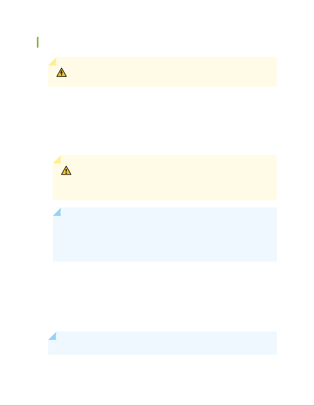
Connecting DC Power to an Optical ILA
WARNING: DC-powered optical ILA models are intended for installation only in a
restricted access location.
Before you begin connecting DC power to the optical ILA:
Read “General Electrical Safety Guidelines and Warnings” on page 152 and “Optical ILA DC Power Electrical
•
Safety Guidelines” on page 155.
Ensure that you have taken the necessary precautions to prevent electrostatic discharge (ESD) damage
•
(see “Prevention of Electrostatic Discharge Damage” on page 153).
Ensure that you have connected the optical ILA chassis to earth ground.
•
CAUTION: Before you connect power to the optical ILA, a licensed electrician must
attach a cable lug to the grounding and power cables that you supply. A cable with
an incorrectly attached lug can damage the switch (for example, by causing a short
circuit).
66
NOTE: To meet safety and electromagnetic interference (EMI) requirements and to ensure
proper operation, you must connect the chassis to earth ground before you connect it to
power. For installations that require a separate grounding conductor to the chassis, use the
protective earthing terminal on the optical ILA chassis to connect to the earth ground (see
“Connecting the Optical ILA Grounding Cable” on page 62).
Install the power supply in the chassis following the instructions in “Installing a Power Supply in an
•
Optical ILA” on page 97.
Ensure that you have the following parts and tools available:
•
ESD grounding strap
•
Power cable or cables appropriate for your geographical location available to connect DC power to
•
the optical ILA.
NOTE: Each power supply must be connected to a dedicated power source outlet.
Page 67

To connect DC power to an optical ILA:
1. To prevent damage to the equipment caused by static discharge, attach an ESD grounding strap to
your bare wrist, and connect the strap to an approved site ESD grounding point.
2. Ensure that the power supplies are fully inserted in the chassis and the latches are secure.
3. Ensure that the power source is turned off, the voltage across the DC power source cable leads is 0 V,
and there is no chance that the cable leads might become active during installation.
4. Locate and remove the three-position DC connectors included in the accessory kit.
5. Identify the ground, positive, and negative feed positions for the DC connector. See
Figure 25 on page 67.
6. Strip each of the three wires coming out from the DC-input power source by 7–8 mm. Do not strip
more than required, because doing so can leave the wire exposed from the DC connector after
installation.
67
Figure 25: Connecting the DC Power Connector
3—1— Ground wirePositive wire
2—Negative wire
7. Insert the stripped wires into the three-position DC connector.
8. Use a ratcheting torque screwdriver to apply a torque of 4.5 lb-in. (0.5 Nm) to each of the terminal
block captive screws (see Figure 25 on page 67).
Page 68

9. Insert the DC connector in the optical ILA DC power supply.
10. Tighten the attached screws (top and bottom) on the DC power connector to apply a torque of 4.5
lb-in. (0.5 Nm). See Figure 25 on page 67.
11. Repeat Step 4 through Step 10 for each power supply you are connecting to power.
WARNING: Ensure that the power cables do not block access to device components
or drape where people can trip on them.
12. Close the input circuit breaker.
NOTE: We recommend that the 48 VDC facility DC source be equipped with a circuit
protector rated at 10 A (–48 VDC) minimum, or as required by local code.
68
We recommend that the 60-VDC facility DC source be equipped with a circuit protector
rated at 5 A (–60 VDC) minimum, or as required by local code.
NOTE: The optical ILA powers on as soon you connect the power.
13. Verify that the status LEDs on each power supply are lit green.
If the DC IN OK or DC OUT OK is lit steadily red, remove power from the power supply, and replace
the power supply (see “Removing a Power Supply from an Optical ILA” on page 95). Do not remove
the power supply until you have a replacement power supply ready: the power supplies or a blank panel
must be installed in the optical ILA to ensure proper airflow.
CAUTION: Replace a failed power supply with a new power supply within one
minute of removal to prevent chassis overheating.
SEE ALSO
Optical ILA Power System | 31
Page 69

Configuring the Software on the Optical ILA
IN THIS SECTION
Performing Initial Software Configuration for the Optical ILA | 69
Optical ILA Modes of Operation | 70
Optical ILA CLI System Commands | 71
Optical ILA CLI show Commands | 72
Optical ILA CLI Configuration Commands | 78
Optical ILA CLI Upgrade Commands | 85
Optical ILA CLI Debug Commands | 86
69
Performing Initial Software Configuration for the Optical ILA
You must perform the initial configuration of the optical ILA through the console port by using the
command-line interface (CLI).
Before you begin connecting and configuring an optical ILA, set the following parameter values on the
management console or console server:
Baud Rate—115200
•
Flow Control—None
•
Data—8
•
Parity—None
•
Stop Bits—1
•
DCD State—Disregard
•
To setup the IP Address:
1. Connect the console port to a laptop or PC by using the supplied RJ-45 cable and RJ-45 to DB-9
adapter. The console port (labeled CON) is located on the management panel of the optical ILA (see
“Connecting the Optical ILA to a Management Console” on page 59 for more information).
2. Log in as the root user. Enter the default password root.
Page 70

3. Start the CLI.
root@localhost:~# /usr/bin/command
Welcome to ILA World
BPS>
4. To enter administration mode, log in as the root user with the password Admin@123.
BPS>login
Username: root
Password: *********
Completed!
BPS>
70
5. Use the CLI console commands to configure, monitor, and troubleshoot the optical ILA.
Optical ILA Modes of Operation
There are two modes of operation for the optical ILA:
Auto mode (default mode). This is the standard operating mode of the optical ILA. Commands issued in
•
the auto mode do not alter the optical behavior of the ILA. Commands in the following sections can be
issued in auto mode:
Optical ILA CLI System Commands on page 71
•
Optical ILA CLI show Commands on page 72
•
Optical ILA CLI Configuration Commands on page 78
•
Optical ILA CLI Upgrade Commands on page 85
•
Manual mode–this mode should only be used to debug the optical ILA. If the commands listed in the
•
“Optical ILA CLI Debug Commands” on page 86 are issued in the auto mode they do not become effective.
These commands alter the optical behavior of the ILA.
Page 71

NOTE: No message is displayed to state these commands (listed in the “Optical ILA CLI Debug
Commands” on page 86) issued in auto mode are not effective.
Commands in the following section can only be issued in manual mode:
Optical ILA CLI Debug Commands on page 86
•
Optical ILA CLI System Commands
Table 23 on page 71 describes the system-level commands for the optical ILA. You can use these commands
to perform system-level functions in both auto mode and manual mode.
Table 23: System Commands (Available in both Auto Mode and Manual Mode)
71
reboot (soft | hard)
exit
DescriptionCommand
Displays the command history.history
Clears the screen.clear
Displays the description of interactive help system.help
Returns to the CLI mode from the admin mode.logout
Logs in to the admin mode.login
Logs in to the shell mode.shell
Reboots the Linux system.
After a hard reset, the settings revert to the default values.
After a soft reset, the optical ILA’s setting is recovered to the state before the reset.
If you have not logged in to the admin mode, the exit command exits the CLI and takes
you back to original Linux shell. If you have logged in to the admin mode, the exit
command logs you out and takes you to the CLI mode.
Page 72

Table 23: System Commands (Available in both Auto Mode and Manual Mode) (continued)
DescriptionCommand
72
shut
Powers off the optical ILA. If you press the ON button for 5 seconds, the optical ILA
starts up.
CAUTION: The following message is displayed when you enter the shut command.
Shutting down this ILA will affect the traffic in both directions and require someone
to physically turn on the system. Do you want to continue (y/n) [n]:
Saves the configuration to persistent storage.save
Pings the destination host IPv6 address.ping6 ipv6-address
Pings the destination host IPv4 address.ping ip-address
Optical ILA CLI show Commands
You can use the following CLI show commands to view, monitor, and troubleshoot the optical ILA in both
auto mode and manual mode.
Table 24 on page 72 describes the system show commands. The output of these commands provides
information about the system parameters.
Table 24: CLI System show Commands (Available in both Auto Mode and Manual Mode)
DescriptionCommand
show cli-time-out
Displays the number of minutes after which an idle login session is timed
out. The default is 0 minutes, which means the login session is never timed
out.
Displays the main board, power, and fan manufacturing information.show mfg-info
Displays the fan, power, or manufacturing EEPROM information.show (fan | power | mfg) id-eeprom
Displays the optical ILA board temperature.show temperature
Displays the temperature threshold for the optical ILA board.show temperature-threshold
Displays the system network parameters.show net
Page 73

Table 24: CLI System show Commands (Available in both Auto Mode and Manual Mode) (continued)
DescriptionCommand
Displays the SNMP user information.show snmp-user
73
show alarm
show log-cfg
Displays the current alarms. See Table 32 on page 106for a list of the alarms
and their descriptions.
Displays all three fan speeds.show fan-status
Displays the time from the startup of the optical ILA to the current time.show uptime
Displays the current optical ILA mode. It is either manual or auto.show ila-mode
Displays the log file path in Secure File Transfer Protocol (SFTP), the maximum
size of the log file, the SFTP username, and the user password.
Displays the optical ILA alarm configuration.show alarm-cfg
Displays the system time.show time
Displays the AC and DC power status.show power-status
Displays the software upgrade status.show upgrade-status
Displays the optical ILA run time, how many hours the ILA has been running.show run-time
Table 25 on page 73 describes the optical show commands. These commands provide information about
the erbium-doped fiber amplifier (EDFA) properties.
NOTE: There are two EDFAs in the optical ILA: one is responsible for A to B direction (for
example, east to west) and is called E-ab; the other one is responsible for B to A direction (for
example, west to east) and is called E-ba. These options are displayed in many of the show edfa
commands in Table 25 on page 73.
Table 25: Optical show Commands (Available in both Auto Mode and Manual Mode)
DescriptionCommand
show edfa-mfg
Displays the EDFA’s manufacturing information, such as model number,
serial number, boot version, hardware version, and so on.
Page 74

Table 25: Optical show Commands (Available in both Auto Mode and Manual Mode) (continued)
DescriptionCommand
74
show edfa (E-ab | E-ba) temperature
show edfa (E-ab | E-ba)
pump-temperature
show edfa (E-ab | E-ba) status
show edfa (E-ab | E-ba) gain
Displays the EDFA’s case temperature. Case temperature measures the
temperature inside the case.
Displays the EDFA’s pump temperature. Pump temperature is the set
operating temperature of the pump.
Displays the EDFA’s status. The status is normal, Output Disabled, or
standby.
The Automatic Power Reduction (APR) status is APR activated or APR
deactivated.
Displays the EDFA’s gain setting in automatic-gain control (AGC) mode.
AGC is a mode of operation in which the optical ILA adjusts it’s gain to
compensate for the preceding span loss. The unit is dB.
Displays the input optical power. The unit is dBm.show edfa (E-ab | E-ba) input-power
Displays the output optical power. The unit is dBm.show edfa (E-ab | E-ba) output-power
Displays the EDFA’s gain working range (GRO or GRI) for the optical power.show edfa (E-ab | E-ba) gain-range
show edfa (E-ab | E-ba) pump
show edfa (E-ab | E-ba) mode
input-power-threshold
show edfa (E-ab | E-ba)
input-power-hysteresis
output-power-threshold
show edfa (E-ab | E-ba)
output-power-hysteresis
Displays the EDFA’s pump status on or off. Off means EDFA output is
disabled; on means that EDFA output is enabled.
Displays the EDFA’s work mode. The mode is AGC or auto-power control
(APC).
Displays the optical power value in the APC mode in dBm.show edfa (E-ab | E-ba) power
Displays the EDFA’s input loss of signal (LOS) alarm threshold in dBm.show edfa (E-ab | E-ba)
Displays the EDFA’s input power hysteresis. The hysteresis is fixed at +/–
1.5 dB.
Displays the EDFA’s output LOS alarm threshold.show edfa (E-ab | E-ba)
Displays the EDFA’s output power hysteresis. The hysteresis is fixed at
+/– 1.5 dB.
Page 75

Table 25: Optical show Commands (Available in both Auto Mode and Manual Mode) (continued)
DescriptionCommand
Displays the power detector information for the selected EDFA.show edfa (E-ab | E-ba) pd
Displays whether the APR is enabled or disabled.show edfa (E-ab | E-ba) apr
Displays the EDFA’s tilt in dB.show edfa (E-ab | E-ba) tilt
Displays the EDFA’s amplified spontaneous emission (ASE) in dBm.show edfa (E-ab | E-ba) ase
Displays whether the EDFA’s standby is on or off.show edfa (a | b) standby
75
show voa (a | b)
show osc (a | b) power
show osc (a | b) output
show osc (a | b) los-threshold
show osc (a | b) los-threshold-hysteresis
Displays the variable optical attenuator (VOA) value.
NOTE: There are two VOAs in the optical ILA. One is called a and the
other is called b.
Displays the optical supervisory channel (OSC) power in dBm.
NOTE: There are two OSCs (a and b) on the optical ILA.
Displays the OSC output status (enabled or disabled).
NOTE: There are two OSCs (a and b) on the optical ILA.
Displays the OSC LOS alarm thresholds (OSC add and drop) for port a or
b.
NOTE: There are two OSCs (a and b) on the optical ILA.
Displays the OSC LOS threshold hysteresis. The value is fixed at +/–
1.5 dB.
NOTE: There are two OSCs (a and b) on the optical ILA.
show osc (a | b) fiber-length
show osc (a | b) oc3-en
show osc (a | b) oc3
Displays the OSC fiber length.
NOTE: There are two OSCs (a and b) on the optical ILA.
Displays whether the oc3-en SONET channel is enabled or disabled.
NOTE: There are two OSCs (a and b) on the optical ILA.
Displays the oc3 SONET channel information.
NOTE: There are two OSCs (a and b) on the optical ILA.
Page 76

Table 25: Optical show Commands (Available in both Auto Mode and Manual Mode) (continued)
DescriptionCommand
Displays span loss for EDFA E-ab and E-ba.show span-loss
Displays output power for the selected port.show port (a | b) out-power
76
show actual voa (a | b)
Displays the actual VOA information for a or b.
There are two VOAs in the optical ILA. One is called a and the other is
called b.
Table 26 on page 76 describes the performance monitoring show commands. These commands provide
information about the performance of the optical ILA.
Table 26: Performance Monitoring show Commands (Available in both Auto Mode and Manual Mode)
DescriptionCommand
show
15-minute-current-performance
Displays current performance data for a 15-minute interval for these items:
osc-a-tx-power, osc-a-rx-power, osc-a-estimated-fiber-loss, voa-a-attenuation,
edfa-ab-input-power, edfa-ab-output-power, edfa-ab-signal-output-power,
edfa-ab-pump0-current, edfa-ab-pump1-current, edfa-ab-pump0-temperature,
edfa-ab-pump1-temperature, osc-b-tx-power, osc-b-rx-power,
osc-b-estimated-fiber-loss, voa-b-attenuation, edfa-ba-input-power,
edfa-ba-output-power, edfa-ba-signal-output-power, edfa-ba-pump0-current,
edfa-ba-pump1-current, edfa-ba-pump0-temperature,
edfa-ba-pump1-temperature
show
15-minute-history-performance
time HHMM
Displays performance data for the 15-minute intervals for the specified time for
these items:
HHMM: Enter hour and minutes.
osc-a-tx-power, osc-a-rx-power, osc-a-estimated-fiber-loss, voa-a-attenuation,
edfa-ab-input-power, edfa-ab-output-power, edfa-ab-signal-output-power,
edfa-ab-pump0-current, edfa-ab-pump1-current, edfa-ab-pump0-temperature,
edfa-ab-pump1-temperature, osc-b-tx-power, osc-b-rx-power,
osc-b-estimated-fiber-loss, voa-b-attenuation, edfa-ba-input-power,
edfa-ba-output-power, edfa-ba-signal-output-power, edfa-ba-pump0-current,
edfa-ba-pump1-current, edfa-ba-pump0-temperature,
edfa-ba-pump1-temperature
Page 77

Table 26: Performance Monitoring show Commands (Available in both Auto Mode and Manual
Mode) (continued)
DescriptionCommand
77
show 15-minute-performance all
show
24-hour-current-performance
Displays the 15-minute performance data for the previous 24-hour period for
these items:
osc-a-tx-power, osc-a-rx-power, osc-a-estimated-fiber-loss, voa-a-attenuation,
edfa-ab-input-power, edfa-ab-output-power, edfa-ab-signal-output-power,
edfa-ab-pump0-current, edfa-ab-pump1-current, edfa-ab-pump0-temperature,
edfa-ab-pump1-temperature, osc-b-tx-power, osc-b-rx-power,
osc-b-estimated-fiber-loss, voa-b-attenuation, edfa-ba-input-power,
edfa-ba-output-power, edfa-ba-signal-output-power, edfa-ba-pump0-current,
edfa-ba-pump1-current, edfa-ba-pump0-temperature,
edfa-ba-pump1-temperature
Displays current performance data over a 24-hour period for these items:
osc-a-tx-power, osc-a-rx-power, osc-a-estimated-fiber-loss, voa-a-attenuation,
edfa-ab-input-power, edfa-ab-output-power, edfa-ab-signal-output-power,
edfa-ab-pump0-current, edfa-ab-pump1-current, edfa-ab-pump0-temperature,
edfa-ab-pump1-temperature, osc-b-tx-power, osc-b-rx-power,
osc-b-estimated-fiber-loss, voa-b-attenuation, edfa-ba-input-power,
edfa-ba-output-power, edfa-ba-signal-output-power, edfa-ba-pump0-current,
edfa-ba-pump1-current, edfa-ba-pump0-temperature,
edfa-ba-pump1-temperature
show
24-hour-history-performance
Displays the performance data for the last 24-hours for these items.
osc-a-tx-power, osc-a-rx-power, osc-a-estimated-fiber-loss, voa-a-attenuation,
edfa-ab-input-power, edfa-ab-output-power, edfa-ab-signal-output-power,
edfa-ab-pump0-current, edfa-ab-pump1-current, edfa-ab-pump0-temperature,
edfa-ab-pump1-temperature, osc-b-tx-power, osc-b-rx-power,
osc-b-estimated-fiber-loss, voa-b-attenuation, edfa-ba-input-power,
edfa-ba-output-power, edfa-ba-signal-output-power, edfa-ba-pump0-current,
edfa-ba-pump1-current, edfa-ba-pump0-temperature,
edfa-ba-pump1-temperature
Page 78

Table 26: Performance Monitoring show Commands (Available in both Auto Mode and Manual
Mode) (continued)
DescriptionCommand
78
show 15-minute tca-threshold
show 24-hour tca-threshold
Displays 15-minute TCA threshold information for these items:
osc-a-tx-power, osc-a-rx-power, osc-a-estimated-fiber-loss, voa-a-attenuation,
edfa-ab-input-power, edfa-ab-output-power, edfa-ab-signal-output-power,
edfa-ab-pump0-current, edfa-ab-pump1-current, edfa-ab-pump0-temperature,
edfa-ab-pump1-temperature, osc-b-tx-power, osc-b-rx-power,
osc-b-estimated-fiber-loss, voa-b-attenuation, edfa-ba-input-power,
edfa-ba-output-power, edfa-ba-signal-output-power, edfa-ba-pump0-current,
edfa-ba-pump1-current, edfa-ba-pump0-temperature,
edfa-ba-pump1-temperature
Displays 24-hour TCA threshold information for these items:
osc-a-tx-power, osc-a-rx-power, osc-a-estimated-fiber-loss, voa-a-attenuation,
edfa-ab-input-power, edfa-ab-output-power, edfa-ab-signal-output-power,
edfa-ab-pump0-current, edfa-ab-pump1-current, edfa-ab-pump0-temperature,
edfa-ab-pump1-temperature, osc-b-tx-power, osc-b-rx-power,
osc-b-estimated-fiber-loss, voa-b-attenuation, edfa-ba-input-power,
edfa-ba-output-power, edfa-ba-signal-output-power, edfa-ba-pump0-current,
edfa-ba-pump1-current, edfa-ba-pump0-temperature,
edfa-ba-pump1-temperature
Displays the 15-minute current alerts.show alert-15m
Displays the 24-hour current alerts.show alert-24h
Optical ILA CLI Configuration Commands
You can use the CLI configuration commands to configure the system parameters and the performance
monitors on the optical ILA in both auto mode and manual mode.
Table 27 on page 79 describes the system configuration commands for the optical ILA. Use these commands
to configure the system parameters.
Page 79

Table 27: System Configuration Commands (Available in both Auto Mode and Manual Mode)
DescriptionCommand
79
set cli-time-out x
set timeYYYYMMDDhhmm.ss
set temperature-threshold high x
set temperature-threshold low x
setnet ipaddress netmask gateway
Sets the CLI timeout period.
x: Number of minutes after which an idle session will be
logged out. The range is 0–60 minutes; 0 means that you
will never be timed out.
Sets the system date and time in the prescribed format.
YYYYMMDDhhmm.ss: Year, month, day, hours, minutes,
seconds.
Sets the high board temperature alarm threshold.
x: Enter a temperature value from the available range. The
range is 55–75° C.
Sets the low board temperature alarm threshold.
x: Enter a temperature value from the available range. The
range is 25–0° C.
Sets the following (IPv4) network parameters:
setnet6 ipaddress gateway
snmp-trap-destination add-v1/v2 ip1 port1 ipN portN
ipaddress: The IPv4 address.
•
netmask: The network mask.
•
gateway: The gateway.
•
Sets the following (IPv6) network parameters:
ipaddress: The IPv6 address.
•
gateway: The gateway.
•
Adds an SNMP V1/V2c user.
ip: The IP address.
•
port: The SNMP port number. The port range is
•
0–65,535.
N: The range is 1–5 SNMP users.
•
Page 80

Table 27: System Configuration Commands (Available in both Auto Mode and Manual Mode) (continued)
DescriptionCommand
80
snmp-trap-destination delete-v1/v2 ip1 port1 ipN portN
snmp-user add-v1/v2c (1 | 2) (trap | notrap) ipaddress
port community (r | w)
snmp-user add-v3 (trap | notrap) ipaddress port community
(r | w) engineid (AuthPriv | AuthNoPriv |
noAuthNoPriv)(MD5 | SHA) authkey (DES | AES) privkey
Deletes an SNMP V1/V2c user.
ip: The IP address.
•
port: The SNMP port number. The port range is
•
0–65,535.
N: The range is 1–5 SNMP users.
•
Adds an SNMP V1/V2c user.
1 | 2: Enter version 1 or 2.
•
ipaddress: The IP address.
•
port: The SNMP port number. The port range is
•
0–65,535.
community: The range is 6-15 characters.
•
r | w: Read or read/write.
•
Adds an SNMP V3 user.
ipaddress: The IP address.
•
port: The port range is 0–65,535.
•
community: The range is 6–15 characters.
•
engineid: The range is 10–128 hexadecimal characters.
•
authkey: The range is 8–15 characters.
•
privKey: The range is 8-15 characters.
•
snmp-user delete-v1/v2c (1 | 2) ipaddress community
snmp-user delete-v3 ipaddress community
set ila-mode (auto | manual)
set log-size x
Deletes an SNMP V1 V2 user.
1 | 2: Enter version 1 or 2.
•
ipaddress: The IP address.
•
community: The range is 6–15 characters.
•
Deletes an SNMP V3 user.
ipaddress: The IP address.
•
community: The range is 6–15 characters.
•
Sets the mode. In auto mode, the software adjusts the
EDFA gain and VOA attenuation automatically by using
the OSC data. The default is auto.
Sets the size of the log file.
x: Enter a value from 1–10, and the unit is MB.
Page 81

Table 27: System Configuration Commands (Available in both Auto Mode and Manual Mode) (continued)
DescriptionCommand
81
ntp-synchronous a.b.c.d
set timezone x
Sets the NTP client and synchronizes the optical ILA clock
with the NTP server.
a.b.c.d: The IP address for the NTP server.
Sets the time zone.
x: The range is –12 through 12. For example, –8 means
GMT–8.
Table 28 on page 82 describes the performance monitoring configuration commands. Use these commands
to configure the attributes for the performance monitors.
Page 82

Table 28: Performance Monitoring Configuration Commands (Available in both Auto Mode and Manual
Mode)
DescriptionCommand
82
set 15-minute a tca-low b
set 15-minute a tca-high c
set 15-minute a tca-low-en d
set 15-minute a tca-high-en d
set 15-minute a tca-low b tca-high c
set 15-minute a tca-low-en d tca-high-en d
Sets the following 15-minute performance monitors:
TCA-low threshold.
•
TCA-high threshold.
•
TCA-low enable or disable option.
•
TCA-high enable or disable option.
•
NOTE: Some of these options can be combined in a
single command.
a: Enter one of these values: osc-a-tx-power,
osc-a-rx-power, osc-a-estimated-fiber-loss,
voa-a-attenuation, edfa-ab-input-power,
edfa-ab-output-power, edfa-ab-signal-output-power,
edfa-ab-pump0-current, edfa-ab-pump1-current,
edfa-ab-pump0-temperature,
edfa-ab-pump1-temperature, osc-b-tx-power,
osc-b-rx-power, osc-b-estimated-fiber-loss,
voa-b-attenuation, edfa-ba-input-power,
edfa-ba-output-power, edfa-ba-signal-output-power,
edfa-ba-pump0-current, edfa-ba-pump1-current,
edfa-ba-pump0-temperature,
edfa-ba-pump1-temperature
b: TCA-low threshold value.
c: TCA-high threshold value.
d: enable or disable
NOTE: You can set your high and low TCA values
provided they do not exceed the values in
Table 29 on page 84 (TCA default values).
Page 83

Table 28: Performance Monitoring Configuration Commands (Available in both Auto Mode and Manual
Mode) (continued)
DescriptionCommand
83
set 24-minute a tca-low b
set 24-minute a tca-high c
set 24-minute a tca-low-en d
set 24minute a tca-high-en d
set 24-minute a tca-low b tca-high c
set 24-minute a tca-low-en d tca-high-en d
Sets the following 24-hour performance monitors:
TCA-low threshold.
•
TCA-high threshold.
•
TCA-low enable or disable option.
•
TCA-high enable or disable option.
•
NOTE: Some of these options can be combined in a
single command.
a: Enter one of these values:osc-a-tx-power,
osc-a-rx-power, osc-a-estimated-fiber-loss,
voa-a-attenuation, edfa-ab-input-power,
edfa-ab-output-power, edfa-ab-signal-output-power,
edfa-ab-pump0-current, edfa-ab-pump1-current,
edfa-ab-pump0-temperature,
edfa-ab-pump1-temperature, osc-b-tx-power,
osc-b-rx-power, osc-b-estimated-fiber-loss,
voa-b-attenuation, edfa-ba-input-power,
edfa-ba-output-power, edfa-ba-signal-output-power,
edfa-ba-pump0-current, edfa-ba-pump1-current,
edfa-ba-pump0-temperature,
edfa-ba-pump1-temperature
b: TCA-low threshold value.
c: TCA-high threshold value.
d: enable or disable
NOTE: You can set your high and low TCA values
provided they do not exceed the values in
Table 29 on page 84 (TCA default values).
Table 29 on page 84 describes the TCA-high and TCA-low values.
Page 84

Table 29: TCA Default Values
osc-a-tx-power
•
osc-b-tx-power
•
osc-a-rx-power
•
osc-b-rx-power
•
osc-a-estimated-fiber-loss
•
osc-b-estimated-fiber-loss
•
84
TCA-LowTCA-HighUnitTCA
06dBmOSC TX power
–45–2dBmOSC RX power
–136dBOSC/FPGA estimated fiber loss
–113dBLine OUT VOA attenuation
voa-a-attenuation
•
voa-b-attenuation
•
edfa-ab-input-power
•
edfa-ba-input-power
•
edfa-ab-output-power
•
edfa-ba-output-power
•
edfa-ab-signal-output-power
•
edfa-ba-signal-output-power
•
edfa-ab-pump0-current
•
edfa-ba-pump0-current
•
–3812dBmEDFA input power (for both EDFAs)
–1321dBmEDFA output power (for both EDFAs)
–1321dBmEDFA signal output power (for both EDFAs)
5See notemAEDFA pump current (for both EDFAs, pump0)
5See notemAEDFA pump current (for both EDFAs, pump1)
edfa-ab-pump1-temperature
•
edfa-ba-pump1-temperature
•
Page 85

Table 29: TCA Default Values (continued)
TCA-LowTCA-HighUnitTCA
2030degrees (C)EDFA pump temperature (for both EDFAs, 2 pumps per
direction)
edfa-ab-pump0-temperature
•
edfa-ba-pump0-temperature
•
edfa-ab-pump1-temperature
•
edfa-ba-pump1-tempe rature
•
–3812dBmPower monitor at input port
–1321dBmPower monitor at output port
NOTE: No fixed value for the EDFA pump current TCA-high limit. The software reads the EOL value for the individual
EDFA pump from an EEPROM and applies it where it is needed.
85
Optical ILA CLI Upgrade Commands
Table 30 on page 85 describes the upgrade commands for the optical ILA. Use these commands to upgrade
the optical ILA software image in both auto mode and manual mode.
Table 30: CLI Upgrade Commands (Available in both Auto Mode and Manual Mode)
DescriptionCommand
Upgrades the optical ILA. The image name is the name of the package.upgrade image-name
ftp-upgrade a b c d e
Downloads the image from an FTP server and upgrades the optical ILA. After the update
is complete, enter the reboot command to restart the optical ILA.
a: FTP server IP address.
•
b: FTP server port; the port range is 0–65535.
•
c: FTP username; the length is 4–16 characters.
•
d: FTP password; the length is 4–16 characters.
•
e: FTP image path and name; the length is 1–50 characters.
•
Page 86

Optical ILA CLI Debug Commands
Table 31 on page 86 describes the optical configuration commands that you can use to debug the optical
ILA. These commands are only available in manual mode.
NOTE: There are two EDFAs in the optical ILA: one is responsible for the A to B direction (for
example, east to west) and is called E-ab; the other one is responsible for the B to A direction
(for example, west to east) and is called E-ba. These options are displayed in many of the EDFA
configuration commands.
Table 31: Optical Configuration Debug Commands (Available only in Manual Mode)
DescriptionCommand
Sets the EDFA gain range.set edfa (E-ab | E-ba) gain-range (low
| high)
86
apc)
set edfa (E-ab | E-ba) gain x
|disable)
set edfa (E-ab | E-ba) power x
set edfa (E-ab | E-ba)
input-power-threshold x
set edfa (E-ab | E-ba)
output-power-threshold x
Sets the EDFA work mode.set edfa (E-ab | E-ba) mode (agc |
Sets the gain value in auto-gain control (AGC) mode.
x: Enter a value. The range is 10.00–35.00 dB.
Enables or disables the automatic power reduction (APR).set edfa (E-ab | E-ba) apr (enable
Sets the EDFA power.
x: Enter a value. The range is 0–20 dBm.
Sets the EDFA input power threshold.
x: Enter a value. The input power threshold range is –41.00 through 11.50.
Sets the EDFA output power threshold.
x: The output power threshold value range is –41.00 through 11.50 dBm.
set edfa (E-ab | E-ba) tilt x
Sets the pump on or off.set edfa (E-ab | E-ba) pump (on | off)
Sets the EDFA tilt.
x: Enter a value. The tilt value range is –3 through 3 dB. The default is 0 dB.
Page 87

Table 31: Optical Configuration Debug Commands (Available only in Manual Mode) (continued)
DescriptionCommand
Sets the EDFA debug mode. To exit the mode, enter control +D.set edfa debug
87
set edfa (E-ab | E-ba) standby on
set voa (a | b) x
set osc (a | b) output (enable |
disable)
set osc (a | b) (add | drop)
los-threshold x
Sets the EDFA into standby mode.
NOTE: When you want to exit standby mode, you need to set gain again and
make sure the IP input power loss of signal (IP_LOS) is off.
NOTE: There are two EDFAs in the optical ILA: one is responsible for the A
to B direction (for example, east to west) and is called E-ab; the other one is
responsible for the B to A direction (for example, west to east) and is called
E-ba.
Resets the EDFA.set edfa reset (soft | hard)
Sets the variable optical attenuator (VOA) value.
NOTE: There are two VOAs on the optical ILA (a and b).
x: Enter a value. The range is 0–25.5. The unit is dB.
Sets the OSC output to enable or disable.
NOTE: There are two OSC ports on the optical ILA (a and b).
Sets the OSC LOS threshold.
NOTE: There are two OSC ports on the optical ILA (a and b).
set osc (a | b) oc3-rx-en (enable |
disable)
set osc (a | b) oc3-tx-en (enable |
disable)
set fan-speed (manual | auto) x
x: Enter a value. The threshold value range is –3.00 through 0.00.
Sets OSC OC-3 rx to enable or disable.
NOTE: There are two OSC ports on the optical ILA (a and b).
Sets OSC OC-3 tx to enable or disable.
NOTE: There are two OSC ports on the optical ILA (a and b).
Restores the device to the factory default settings.reload
Sets the percentage of the fan speed.
x: Enter the fan speed. The range is 50–100.
Page 88

Table 31: Optical Configuration Debug Commands (Available only in Manual Mode) (continued)
DescriptionCommand
88
set virtual-alarm x (0 | 1 | 2)
Sets the virtual alarm.
x: Enter one of the following values: oplinkilaBoardTemperatureAbnormal,
oplinkilaPower1Abnormal, oplinkilaPower0Abnormal, oplinkilaFan0Missing,
oplinkilaFan1Missing, oplinkilaFan2Missing, oplinkilaFan0SpeedAbnormal,
oplinkilaFan1SpeedAbnormal, oplinkilaFan2SpeedAbnormal,
oplinkilaSoftwareVersionAbnormal, oplinkilaCommunicationAbnormal,
oplinkilaTableErr, edfaEabCaseTemperature, edfaEabRFL, edfaEabOOP,
edfaEabOOG, edfaEabPump0EOL, edfaEabPump1EOL,
edfaEabPump0Temperature, edfaEabPump1Temperature, edfaEabInputLOS,
edfaEabOutputLOS, edfaEabCaliTableErr, edfaEbaCaseTemperature,
edfaEbaRFL, edfaEbaOOP, edfaEbaOOG, edfaEbaPump0EOL,
edfaEbaPump1EOL, edfaEbaPump0Temperature, edfaEbaPump1Temperature,
edfaEbaInputLOS, edfaEbaOutputLOS, edfaEbaCaliTableErr,
oscaAddPowerLOS, oscaDropPowerLOS, oscbAddPowerLOS,
oscbDropPowerLOS
y: 0 (force alarm disappear), 1 (force alarm appear) 2(enable actual alarm, disable
virtual alarm).
RELATED DOCUMENTATION
Optical ILA Alarm Messages Overview | 105
Powering Off an Optical ILA
NOTE: Use the following procedure to power off an optical ILA.
Before you power off an optical ILA:
Ensure that you have taken the necessary precautions to prevent electrostatic discharge (ESD) damage.
•
See “Prevention of Electrostatic Discharge Damage” on page 153.
Ensure that you do not need to route traffic through the optical ILA.
•
Page 89

Ensure that you have the following parts and tools available to power off the optical ILA:
•
An ESD grounding strap
•
An external management device such as a PC
•
An RJ-45 to DB-9 rollover cable to connect the external management device to the console port
•
To power off an optical ILA by using the shut CLI command:
1. Connect to the device by using one of the following methods:
Connect a management device to the console (CON) port on an optical ILA by following the instructions
•
in “Connecting the Optical ILA to a Management Console” on page 59.
Connect a management device to the management (MGMT) port by following the instructions in
•
“Connecting the Optical ILA to a Management Ethernet Device” on page 58.
2. Shut down the optical ILA by using the shut CLI command. This command shuts down the optical ILA
and powers off the unit.
89
CAUTION: The following message is displayed when you enter the shut command.
BPS->shut down
Shutting down this ILA will affect the traffic in both directions and require
someone to physically turn on the system. Do you want to continue (y/n) [n]:
Enter y to shut down the ILA.
3. To prevent damage to the equipment caused by static discharge, attach an ESD grounding strap to
your bare wrist, and connect the strap to one of the ESD points on the chassis.
4. Disconnect power to the optical ILA:
AC power supply—If the AC power source outlet has a power switch, set it to the off (O) position. If
•
the AC power source outlet does not have a power switch, gently pull out the plug end of the power
cord connected to the power source outlet.
DC power supply—Switch the circuit breaker on the panel board that services the DC circuit to the
•
off position.
5. Remove the power source cable from the power supply faceplate:
AC power supply—Gently pull out the socket end of the power plug connected to the power supply
•
faceplate.
Page 90

DC power supply—Loosen the screws for the power connector and remove the connector.
•
RELATED DOCUMENTATION
Connecting AC Power to an Optical ILA | 63
Connecting DC Power to an Optical ILA | 66
90
Page 91

4
CHAPTER
Maintaining Components
Maintaining the Optical ILA Cooling System | 92
Maintaining Power Supplies | 95
Maintaining the Optical ILA Fiber-Optic Cables | 99
Removing an Optical ILA from a Rack or Cabinet | 102
Page 92

Maintaining the Optical ILA Cooling System
IN THIS SECTION
Removing a Fan Module from an Optical ILA | 92
Installing a Fan Module in an Optical ILA | 93
Removing a Fan Module from an Optical ILA
The fan modules in an optical ILA are hot-removable and hot-insertable field-replaceable units (FRUs)—you
can remove and replace them without powering off the optical ILA or disrupting optical ILA functions.
92
CAUTION: Replace the fan module within 30 seconds of removal to prevent chassis
overheating. Before removing the fan module, ensure that you have a replacement
fan module available.
Before you remove a fan module from an optical ILA, ensure that you have taken the necessary precautions
to prevent electrostatic discharge (ESD) damage (see “Prevention of Electrostatic Discharge Damage” on
page 153).
Ensure that you have the following parts and tools available:
ESD grounding strap
•
Antistatic bag or an antistatic mat
•
Phillips (+) screwdriver, number 2
•
To remove a fan module from an optical ILA (see Figure 26 on page 93):
1. Place the antistatic bag or the antistatic mat on a flat, stable surface.
2. To prevent damage to the equipment caused by static discharge, attach an ESD grounding strap to
your bare wrist, and connect the strap to one of the ESD points on the chassis.
3. Using a screwdriver, loosen the captive screws on the side of the fan.
4. Grasp the large captive screws on the fan module to slide the fan module halfway out of the chassis.
Page 93
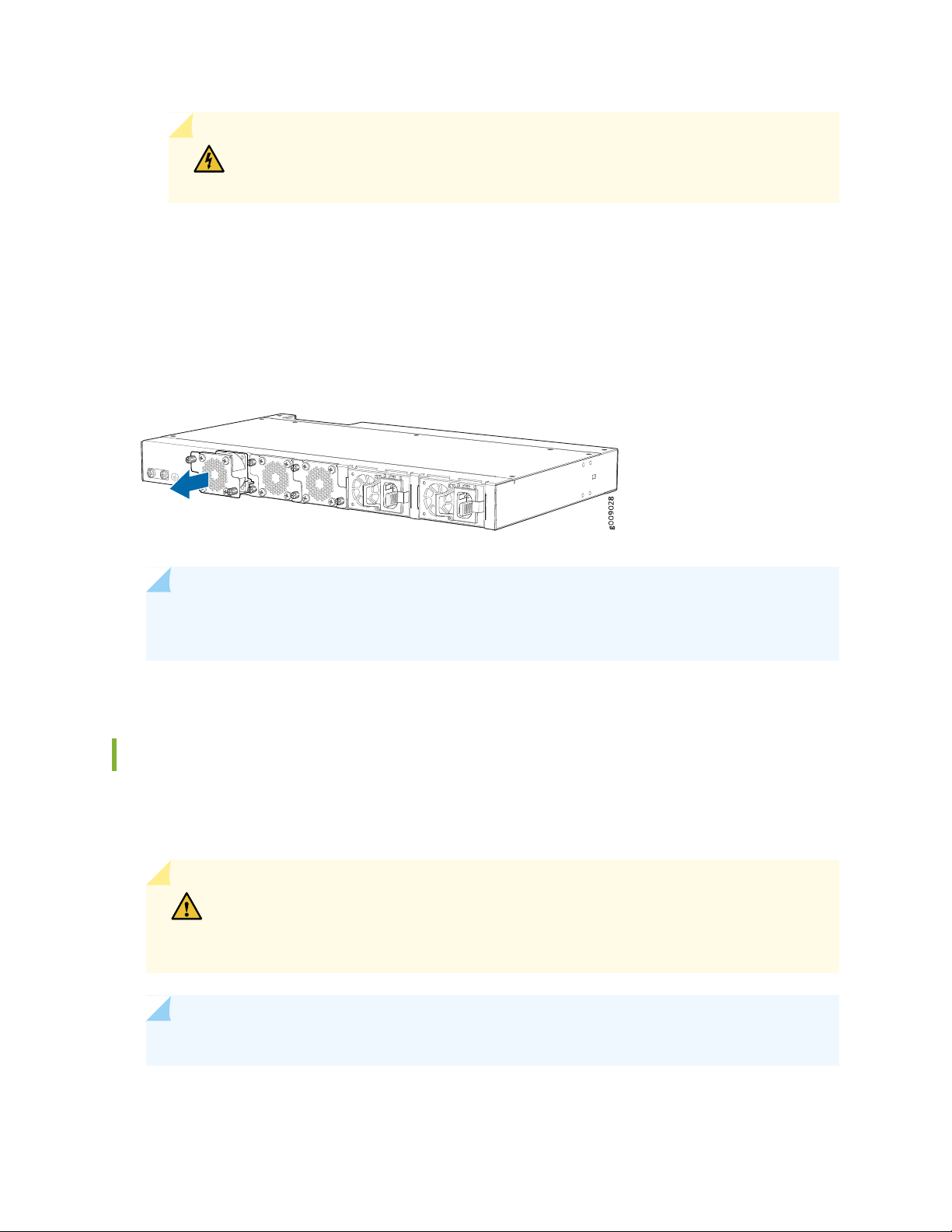
WARNING: To avoid injury, do not touch the fan with your hands or any tools as
you slide the fan module out of the chassis—the fan might still be running.
5. When the fan stops rotating, slide the fan module completely out of the chassis.
6. Place the fan module in the antistatic bag or on the antistatic mat placed on a flat, stable surface.
Figure 26: Removing a Fan Module from an Optical ILA
93
NOTE: When a fan module is removed, the system raises an alarm. You can enter the show
alarm CLI command to view the message.
Installing a Fan Module in an Optical ILA
The fan modules in an optical ILA are hot-removable and hot-insertable field-replaceable units (FRUs)—you
can remove and replace them without powering off the optical ILA or disrupting routing functions.
CAUTION: Replace the fan module within 30 seconds of removal to prevent chassis
overheating. Before removing the fan module, ensure that you have a replacement
fan module available.
NOTE: The fan module provides airflow out, which is also known as front-to-back airflow.
Page 94

Before you install a fan module in an optical ILA, ensure that you have taken the necessary precautions
to prevent electrostatic discharge (ESD) damage (see “Prevention of Electrostatic Discharge Damage” on
page 153 ).
Ensure that you have the following parts and tools available:
ESD grounding strap
•
Phillips #2 (+) screwdriver
•
To install a fan module in an optical ILA (see Figure 27 on page 94):
1. To prevent damage to the equipment caused by static discharge, attach an electrostatic discharge (ESD)
grounding strap to your bare wrist, and connect the strap to one of the ESD points on the chassis.
2. Taking care not to touch the connectors, remove the fan module from its bag.
3. Align the module with the open slot on the FRU end of the optical ILA and slide it in until it is fully
seated.
94
4. Use a screwdriver to secure the captive screws tightly on each side.
Figure 27: Installing a Fan Module in an Optical ILA
RELATED DOCUMENTATION
Optical ILA Field-Replaceable Units | 20
Page 95

Maintaining Power Supplies
IN THIS SECTION
Removing a Power Supply from an Optical ILA | 95
Installing a Power Supply in an Optical ILA | 97
Removing a Power Supply from an Optical ILA
The power supplies in an optical ILA are hot-removable and hot-insertable field-replaceable units
(FRUs)—you can remove and replace them without powering off the optical ILA or disrupting optical ILA
functions.
95
CAUTION: Replace the power supply within 1 minute of removal to prevent chassis
overheating. Before removing the power supply, ensure that you have a replacement
power supply available or install a blank cover.
Before you remove a power supply from an optical ILA, ensure that you have taken the necessary
precautions to prevent electrostatic discharge (ESD) damage (see “Prevention of Electrostatic Discharge
Damage” on page 153).
Ensure that you have the following parts and tools available:
ESD grounding strap
•
Antistatic bag or an antistatic mat
•
To remove a power supply from an optical ILA (see Figure 28 on page 96 and Figure 29 on page 97):
1. Place the antistatic bag or the antistatic mat on a flat, stable surface.
2. To prevent damage to the equipment caused by static discharge, attach an ESD grounding strap to
your bare wrist, and connect the strap to one of the ESD points on the chassis.
Page 96

NOTE: If you will be removing all the power supplies installed in your optical ILA, you need
to power off the optical ILA before removing the power supplies. See “Powering Off an
Optical ILA” on page 88.
3. Disconnect power to the optical ILA:
AC power supply—If the AC power source outlet has a power switch, set it to the off (O) position. If
•
the AC power source outlet does not have a power switch, gently pull out the plug end of the power
cord connected to the power source outlet.
DC power supply—Switch the circuit breaker on the panel board that services the DC circuit to the
•
off position.
4. Remove the power source cable from the power supply faceplate:
AC power supply—Gently pull out the socket end of the power plug connected to the power supply
•
faceplate.
96
DC power supply—Loosen the screws for the power connector and remove it.
•
5. Slide the locking lever toward the handle until it stops.
6. Grasp the power supply handle and pull firmly to slide the power supply halfway out of the chassis.
7. Place one hand under the power supply to support it and slide it completely out of the chassis. Take
care not to touch power supply components, pins, leads, or solder connections.
Figure 28: Removing an AC Power Supply from an Optical ILA
Page 97

Figure 29: Removing a DC Power Supply from an Optical ILA
8. Place the power supply in the antistatic bag or on the antistatic mat placed on a flat, stable surface.
Installing a Power Supply in an Optical ILA
97
The power supplies in an optical ILA are hot-removable and hot-insertable field-replaceable units
(FRUs)—you can remove and replace them without powering off the optical ILA or disrupting the ILA
functions.
CAUTION: Replace the power supply within 1 minute of removal to prevent chassis
overheating. Before removing the power supply, ensure that you have a replacement
power supply available.
Before you install a power supply in an optical ILA, ensure that you have taken the necessary precautions
to prevent electrostatic discharge (ESD) damage (see “Prevention of Electrostatic Discharge Damage” on
page 153).
Ensure that you have the following parts and tools available:
ESD grounding strap
•
To install a power supply in an optical ILA (see Figure 30 on page 98 and Figure 31 on page 98):
1. To prevent damage to the equipment caused by static discharge, attach an ESD grounding strap to
your bare wrist, and connect the strap to one of the ESD points on the chassis.
2. Taking care not to touch power supply components, pins, leads, or solder connections, remove the
power supply from its bag.
Page 98

3. Using both hands, place the power supply in the power supply slot on the FRU panel of the optical ILA
and slide it in until it is fully seated and the locking lever slides into place.
Figure 30: Installing an AC Power Supply in an Optical ILA
98
Figure 31: Installing a DC Power Supply in an Optical ILA
See “Connecting AC Power to an Optical ILA” on page 63 to connect the AC power supply. See “Connecting
DC Power to an Optical ILA” on page 66 to connect the DC power supply.
NOTE: Each power supply must be connected to a dedicated power source outlet.
NOTE: If you have a Juniper Care service contract, register any addition, change, or upgrade of
hardware components at https://www.juniper.net/customers/support/tools/updateinstallbase/.
Failure to do so can result in significant delays if you need replacement parts. This note does
not apply if you replace existing components with the same type of component.
Page 99

RELATED DOCUMENTATION
Connecting AC Power to an Optical ILA | 63
Connecting DC Power to an Optical ILA | 66
Optical ILA AC Power Specifications | 36
Optical ILA DC Power Specifications | 37
Optical ILA DC Power Cable and Lugs Specifications | 38
Maintaining the Optical ILA Fiber-Optic Cables
IN THIS SECTION
Disconnect a Fiber-Optic Cable | 99
99
Connect a Fiber-Optic Cable | 100
How to Handle Fiber-Optic Cables | 101
Disconnect a Fiber-Optic Cable
Juniper Networks devices have optical transceivers to which you can connect fiber-optic cables.
Before you begin to disconnect a fiber-optic cable from an optical transceiver, ensure that you have taken
the necessary precautions for safe handling of lasers. See Laser and LED Safety Guidelines and Warnings.
Ensure that you have the following parts and tools available:
A rubber safety cap to cover the transceiver
•
A rubber safety cap to cover the fiber-optic cable connector
•
Page 100

To disconnect a fiber-optic cable from an optical transceiver installed in the device:
1. Disable the port in which the transceiver is installed by issuing the following command:
[edit interfaces]
user@device# set interface-name disable
WARNING: Do not look directly into a fiber-optic transceiver or into the ends of
fiber-optic cables. Fiber-optic transceivers and fiber-optic cables connected to
transceivers emit laser light that can damage your eyes.
2. Carefully unplug the fiber-optic cable connector from the transceiver.
3. Cover the transceiver with a rubber safety cap.
100
WARNING: Do not leave a fiber-optic transceiver uncovered except when inserting
or removing a cable. The rubber safety cap keeps the port clean and prevents
accidental exposure to laser light.
4. Cover the fiber-optic cable connector with the rubber safety cap.
Connect a Fiber-Optic Cable
Before you begin to connect a fiber-optic cable to an optical transceiver installed in a device, ensure that
you have taken the necessary precautions for safe handling of lasers (see Laser and LED Safety Guidelines
and Warnings).
 Loading...