

Page 1
Optical Inline Amplifier Quick Start
See the complete PTX Series documentation at
http://www.juniper.net/techpubs/.
To install, connect power to, and configure the Juniper Networks
Optical Inline Amplifier, you need:
z Electrostatic discharge (ESD) grounding strap (not provided).
z Four screws to secure the chassis and mounting brackets to the
rack (not provided).
z Screwdriver appropriate for the rack-mounting screws (not provided).
z Two power cords with plugs appropriate for your geographical location (provided with
the AC model).
z Two DC power connectors (provided with the DC model).
z Power cable or cables appropriate for your geographical lo cation available to connect
DC power to the optical ILA (not provided).
z RJ-45 cable and RJ-45 to DB-9 serial port adapter (provided).
z Management host, such as a PC laptop, with a serial port (not provided).
z (Optional) Grounding cable with lug, screws, and washers (not provided).
z (Optional) 23-in. mounting brackets (provided).
Part 1: Mount the Optical ILA
The optical inline amplifier (optical ILA) can be mounted on a two-post rack.
NOTE: Place the rack in its permanent location, allowing adequate clearance for airflow
and maintenance, and secure it to the building structure. If you are mounting multiple
units in the rack, mount the heaviest unit at the bottom and mount the other units from
bottom to top in order of decreasing weight. The DC-powered optical ILA weighs 11.8 lb
(5.35 kg) and the AC-powered optical ILA weighs 11.7lb (5.30 kg).
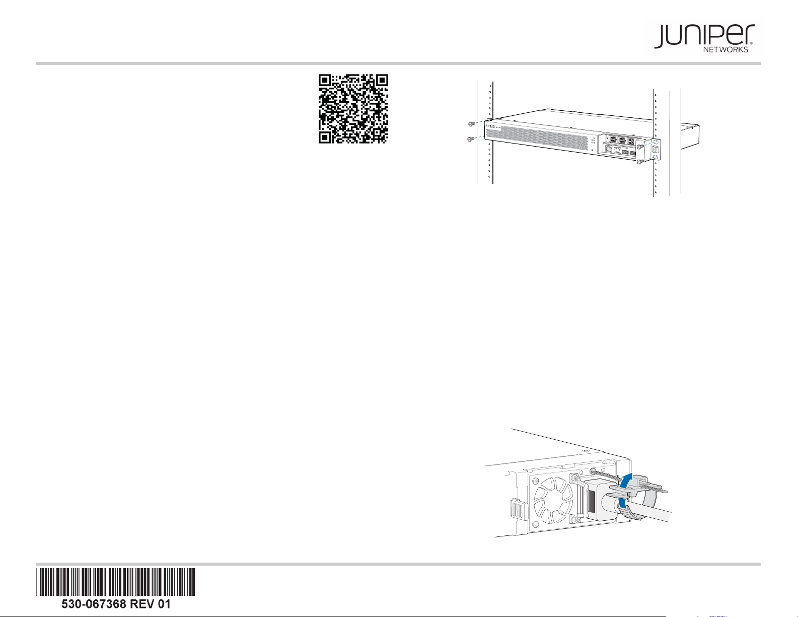
To mount the optical ILA on two posts of a rack by using the provided mounting kit:
1. Attach the ESD grounding strap to your bare wrist and to a site ESD point.
2. Position the optical ILA in such a manner that the FRUs are next to the hot aisle.
NOTE: The 19-in. brackets are attached to the optical ILA when they are shipped. If you
want to attach the 23-in. brackets, unscrew the 19-in. brackets from the chassis, and
attach the 23-in. brackets by using the same screws.
3. Use four mounting screws (and cage nuts and washers if your rack requires them) to
attach the optical ILA to the rack as shown in the illustration.
L
I
NE
S
Y
A
S
I
N
L
I
N
E
B
OS
C
A
A
L
O
SCB
PW
O
N
/
O
F
F
IN
M
O
N
A
O
U
M
R
T
L
I
N
E
A
O
U
T
L
I
NE
B
O
U
T
MO
N
B
O
U
T
CON
M
G
M
T
US
B
US
B
g009048
4. Tighten the screws.
5. (Optional) Attach a grounding cable to earth ground and then attach it to the chassis
grounding point.
Part 2: Connect Power to the Optical ILA
The optical ILA is supplied with two factory-installed power supplies. For instructions on
connecting DC power, see the installation instructions in the Optical Inline Amplifier
Hardware Guide.
To connect power to an optical ILA with AC power supplies:
1. To prevent damage to the equipment caused by static discharge, attach an ESD
grounding strap to your bare wrist, and connect the strap to an approved site ESD
grounding point.
2. Ensure that the power supplies are fully inserted in the chassis and the latches are
secure.
3. If the AC power source outlet has a power switch, set it to the off (O) position.
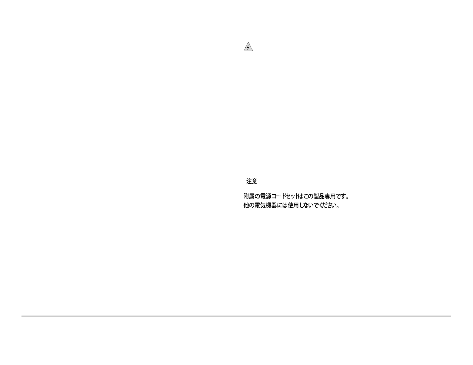
4. Insert the coupler end of the power cord into the AC power cord inlet on the AC
power supply faceplate.
5. Open the power cord retainer by pressing the protruding tab and prying it open. Wrap
the power cord retainer around the AC power cord and push the cable clamp through
the hole to tighten.
g009037
Page 2
6. Repeat the steps for each power supply you are connecting.
7. Insert the power cord plug into an AC power source outlet.
NOTE: The optical ILA powers on as soon as power is provided to the power supply.
8. If the AC power source outlet has a power switch, set it to the on (|) position.
9. Verify that the status LED for each power supply is lit green and is on steadily.
Part 3: Perform the Initial Configuration
You must perform the initial configuration of the optical ILA through the console port.
Before you begin, set the following parameter values from the console server or PC:
z Baud Rate—115200
z Flow Control—None
z Data—8
z Parity—None
z Stop Bits—1
z DCD State—Disregard
To connect and configure the optical ILA from the console:
1. Connect the console port to a laptop or PC by using the provided RJ-45 cable and
RJ-45 to DB-9 serial port adapter. The console (CON) port is located on the
management panel of the optical ILA.
2. Log in as the root user. Enter the default password root.
login: root
3. Start the command-line interface (CLI).
root@% localhost:~# /usr/bin/command
Welcome to ILA World
Safety Warnings Summary
This is a summary of safety warnings. For a complete list of warnings, including
translations, see the optical ILA documentation at http://www.juniper.net/techpubs/.
WARNING: Failure to observe these safety warnings can result in personal injury
or death.
z Only trained and qualified personnel are permitted to install or replace the optical ILA
components.
z Perform only the procedures described in this quick start and the optical ILA
documentation. Other services must be performed by authorized service personnel.
z Before installing the optical ILA, read the pl anning instructions in the optical ILA
documentation to make sure that the site meets power, environmental, and clearance
requirements for the optical ILA.
z Before connecting the optical ILA to a power source, read the installation instructions
in the optical ILA documentation.
z If the rack or cabinet has stabilizing devices, install them in the rack before mounting or
servicing the optical ILA in the rack or cabinet.
z Before installing or after removing an electrical component, always place it
component-side up on a flat antistatic mat or in an antistatic bag.
z Do not work on the optical ILA or connect or disconnect cables during electrical
storms.
z Before working on equipment that is connected to power lines, remove jewelry,
including rings, necklaces, and watches. Metal objects heat up when connected to
power and ground and can cause serious burns or become welded to the terminals.
BPS>
4. To enter the administrative mode, log in as the root user with password Admin@123.
BPS>login
Username
Password
: root
: *********
Contacting Juniper Networks
For technical support, see:
http://www.juniper.net/support/requesting-support.html
Completed!
BPS>
5. Y ou can use the CLI commands documented in the Optical Inline Amplifier Hardware
Guide to configure, monitor, and troubleshoot the optical ILA.
Juniper Networks, Junos, Steel-Belted Radius, NetScreen, and ScreenOS are registered trademarks of Juniper Networks, Inc. in the United States and other countries. The Juniper Networks Logo, the Junos logo, and JunosE are
trademarks of Juniper Networks, Inc. All other trademarks, service marks, registered trademarks, or re gistered service marks are the property of their respe ctive owners. Juniper Ne tworks assumes no responsibility for any inaccuracies
in this document. Juniper Networks reserves the right to change, modify, transfer, or otherwise revise this publication without notice. Products made or sold by Juniper Networks or components thereof might be covered by one or more
of the following patents that are owned by or licensed to Juniper Networks: U.S. Patent Nos. 5,473,599, 5,905,725, 5,909,440, 6,192,051, 6,333,650, 6,359,479, 6,406,312, 6,429,706, 6,459,579, 6,493,347, 6,538,518, 6,538,899,
6,552,918, 6,567,902, 6,578,186, and 6,590,785. Copyri ght © 2016 Juniper Networks, Inc. All rights reserved. Printed in Malaysia. Part Number: 530-067368 Revision 01, 1 April 2016.
 Loading...